Embed Size (px)
Citation preview
1
UNIVERSITY GRANTS COMMISSION
BAHADUR SHAH ZAFAR MARG
NEW DELID -110 002
Annexure - IX
PROFORMA FOR SUBMISSION OF INFORMATION AT THE TIME OF SENDING
THE FINAL REPORT OF THE WORK DONE ON THE PROJECT
1. NAME AND ADDRESS OF Dr. Sukhmeet Singh THE PRINCIPAL Research Engineer INVESTIGATOR School of Renewable Energy Engineering,
College of Agricultural Engineering and
Technology, P AU Ludhiana 2. NAME AND ADDRESS OF PAU, Ludhiana
THE INSTITUTION
3. UGC APPROVAL NO. AND 42-884/2013 (SR), 25-03-2013 DATE
4. DATE OF 1 April 2013
IMPLEMENTATION
5. TENURE OF THE PROJECT 4 years
6. TOTAL GRANT Rs. 7 ,70,000/-
ALLOCATED
7. TOT AL GRANT RECEIVED Rs. 7 ,70,000/-
8. FINAL EXPENDITURE Rs. 7 ,63,567 /-
9. TITLE OF THE PROJECT CFD analysis of rib-roughened solar air heater
duct
10. OBJECTIVES OF THE (i) ·Validation of published results of heat
PROJECT and fluid flow through rib roughened
solar air heater duct using CFD.
(ii) CFD investigations on heat and fluid
flow of solar air heater duct roughened
with rib roughness.
(iii) Development of correlations of Nusselt
number and friction factor for rib-roughened solar air heater duct as function of Reynolds number and
2
3

4
1.
2.
3.
4.
5.
6.
7.
Annexure -VIII
UNIVERSITY GRANTS COMMISSION
BAHADUR SHAH ZAFAR MARG
NEW DELHI - 110 002
Final Report of the work done on the Major Research Project Project report No. Final UGC Reference No. & 42-884/2013 (SR), 25-03-2013
Date
Period of report From 1 April 2013 to 31 March 2017 Title of the Project CFD analysis of rib-roughened solar air heater
duct
(a) Name of the Principal Dr. Sukhmeet Singh
Research Engineer
(b) Department School of Renewable Energy Engineering
(c) University/College College of Agricultural Engineering &
where work has Technology, Punjab Agricultural University,
progressed Investigator Ludhiana
Effective date of starting the 1April2013
project
Grant approved and expenditure incurred during the period of the report:
(a) Total amount approved Rs. 7,70,000/-
(b) Total expenditure Rs.7,63,567/-
(c) Report of the work Please see Annexure B
· done:
~~R ~-":i.'\ \ b }\?r
CO-INVES rIGAT J#A{<;W ~ School of Renewable Energy Engmeermg
P.A.U .. LUDHIANA.
~?-'J,l'/fVJ DIRECTOR OF RESEARCH
Otreetor ot Research Punjab Agricultural Onlveralty. Ludhfana.

5
s.
Annexure - III
UNIVERSITY GRANTS COMMISSION
BAHADUR SHAH ZAFAR MARG
NEWDELID-110 002
STATEMENT OF EXPENDITURE IN RESPECT OF MAJOR RESEARCH
PROJECT
1. Name of the Principal
Investigator
2. Deptt. of Principal
Investigator
University/ College
3. UGC approval Letter No.
and Date
4. Title of the Project
5. Effective date of starting
the project
6. a. Period of Expenditure:
b. Details of Expenditure
Dr. Sukhmeet Singh
School of Renewable Energy Engineering,
College of Agricultural Engineering &
Technology
Punjab Agricultural University, Ludhiana
42-884/2013 (SR), 25 March 2013
CFD analysis of rib-roughened solar air heater
duct
I April 2013
From I ~pril 2013 to 31March 2017
Items Amount Amount Expenditure ' I l
No. Approved (Rs) Received(Rs) / incurred so far I
(Rs)
A. Non-Recurring
1. Books & Journals 20,000/- 20,000/- 13,729/-
2. Equipment 7,50,000/- 7,50,000/- 7,49,838/-
B. Recurring Nil Nil Nil
1. Honorarium Nil Nil Nil
2. Project Fellow~ Nil Nil Nil
3. Chemical I Glas.sware Nil Nil Nil
/Consumable
4. Hiring Services Nil Nil Nil
5. Contingency Nil Nil Nil
6. Travel I field work Nil Nil Nil

6
7. Special need Nil Nil Nil
8. Overhead charges Nil Nil Nil
Total (A+B)
c. Staff:
Date of Appointment
7,70,000/-
None
NIA
7,70,000/- 7,63,567/-
1. It is certified that the appointment(s) have been made in accordance with the terms and
conditions laid down by the Commission.
2. If as a result of check or audit objection some irregularly is noticed at later date, action
will be taken to refund, adjust or regularize the objected amounts .
3. Payment @ revised rates shall be made with arrears on the availability of additional funds.
4. It is certified that the grant o.f Rs. 7,70,000/- (Rupees Seven lakh and seventy
thousand only) received from the University 9rants Commission under the Scheme of
support for Major Research Project entitled,"CFD analysis of rib-roughened solar air
heater duct" vide UGC Letter No. F. 42-884/2013 (SR) dated 25 March 2013. Out of
which Rs 7,63,567/- has been utilized for the purpose for which it was sanctioned and in
accordance with the terms and conditions laid down by the University Grants Commission.
~~'~''" CO-INVESTIGATOR
d s.m. l'ruj. u; M ech. Zntg, Punjab Agric.:11J1ural U• /,er.1t';;,' l.UDF!..1.M ,i. ______ 1
~vz.-8-5·7•17 DIRECTOR OF RESEARCH
•*'o' of Research hn)ab Aarlcultaral 1'11boralt,1 Ludhiana.
7
Annexure - IV
UNIVERSITY GRANTS COMMISSION
BAHADUR SHAH ZAFAR MARG
NEW DELHI - 110 002
STATEMENT OF EXPENDITURE INCURRED ON FIELD WORK
Name of the Principal Investigator: Dr. Sukhmeet Singh
Expenditure incurred on field work: Nil
Certified that the above expenditure is in accordance with the UGC norms for Major Research
Projects.
~~'7 pn~fi1)1l ~g~~STIGATOR ~ctioOt oiltenewable ~nergy Engmeermg
P. A.U., LUDHIANA.
~~1~111 CO-INVESTIGATOR tt sm, ./'ro/. of Mtcll. En11, Punjab Agricultural Unl~erltr,, l,UDRIANA • ....... -
~ 617•17 DIRECTOR OF RESEARCH
Dnetor of Research Punjab Agricultural Omvcralt.J. tudhfana.
8
UNIVERSITY GRANTS COMMISSION
BAHADUR SHAH ZAFAR MARG
NEW DE LID - 110 002
Utilization certificate
Annexure-V
Certified that the grant of Rs. 7, 70,000/- (Rupees Seven Jakh and sevety thousand only)
received from the University Grants Commission under the scheme of support for Major
Research Project entitled, "CFD analysis of rib-roughened solar air heater duct" vide
UGC letter No. F. 42-884/2013 (SR) dated 25 March 2013. Out of which Rs 7,63,567/- has
been utilized for the purpose for which it was sanctioned and in accordance with the terms
and conditions laid down by the University Grants Commission (Audited Report attached).
,,;'l_f-1\I\\':\' ~ ~ ~ O' &::>..,\.,It? CO-INVESTIGATOR rrtt~!<\D OF DE'P A'RTMENT
Assn. Prof. •f M~ch. Engg. School of Renewable Ener E ineeri Research E,n,s;~~ C'
School of ~b~e~lEMl!ly\ l~&irmg Punjab Agrlculrural Uo1Yerst1y, PAU, Ludhiana gy ng ng P.A.U., LUDHJA"'A. f.UDHTANA ; ....----
~6·'7.- f7 DIRECTOR OF RESEARCH
l»rector ot Research Punjab Ai rlcultnraJ O'mveral~ tudhlaoa. ·-"'
\ ~"' ~.,,t
t':omptrolloo p~ Algs'fW¥tJ!JlcJiWvei s?tf,
A~6ib~~MPTROLLER
9
10
Annexure A
SUMMARY OF THE FINDINGS
Summarizing the CFD investigation on rib roughness in solar air heater duct, a new type of rib roughness having non-uniform cross-section has been studied. It has been found to produce higher thermal performance than ribs of uniform cross-section. In this study, a parametric investigation on non-uniform saw-tooth cross-section rib roughness has been undertaken to investigate heat and fluid flow of solar air heater duct roughened with saw-tooth transverse rib roughness. The correlations for Nusselt number and friction factor have also been obtained. The investigation has been done in 3-D using CFD software ANSYS Academic Research 15.0. The relative roughness height (e/D), saw-tooth angle (θ) and relative roughness pitch (P/e) were varied from 15° to 75°, 0.015 to 0.043 and 4 to 30 respectively. The Reynolds number ranged from 3000 to 15000. Turbulence model RNG k-ε and roughened duct of periodic section were selected for analysis. From the present study, it has been found that as Reynolds number increases, friction factor decreases and Nusselt number increases. The variation of static temperature contours on absorber also confirms this trend. As relative roughness pitch increases from 4 to 16, the friction factor and Nusselt number increases and then both decreases as relative roughness pitch is increased from 16 to 30. This is because of change in flow attachment in-between the ribs. The variation is further substantiated by the turbulent kinetic energy, static temperature and static pressure contours showing same trend. Both, the friction factor and Nusselt number are maximum for saw-tooth angle of 45° for all investigated Reynolds number. As relative roughness height increases, friction factor and Nusselt number increases for all investigated Reynolds number due to higher turbulence generated due to obstruction in flow path. The relative roughness pitch of 0.043, saw-tooth angle of 45°, relative roughness pitch of 16 and Reynolds number of 9000 resulted in maximum ‘thermo-hydraulic performance parameter’ of 1.48. The correlations of Nusselt number (Nu) and friction factor (f) have been obtained from CFD investigation in terms of Reynolds number, relative roughness pitch, relative roughness height and angle of saw tooth. The respective R2 values obtained are 0.972 and 0.392 thereby indicating that the fitted model is highly significant (p<0.001).
11
Annexure B REPORT OF THE WORK DONE
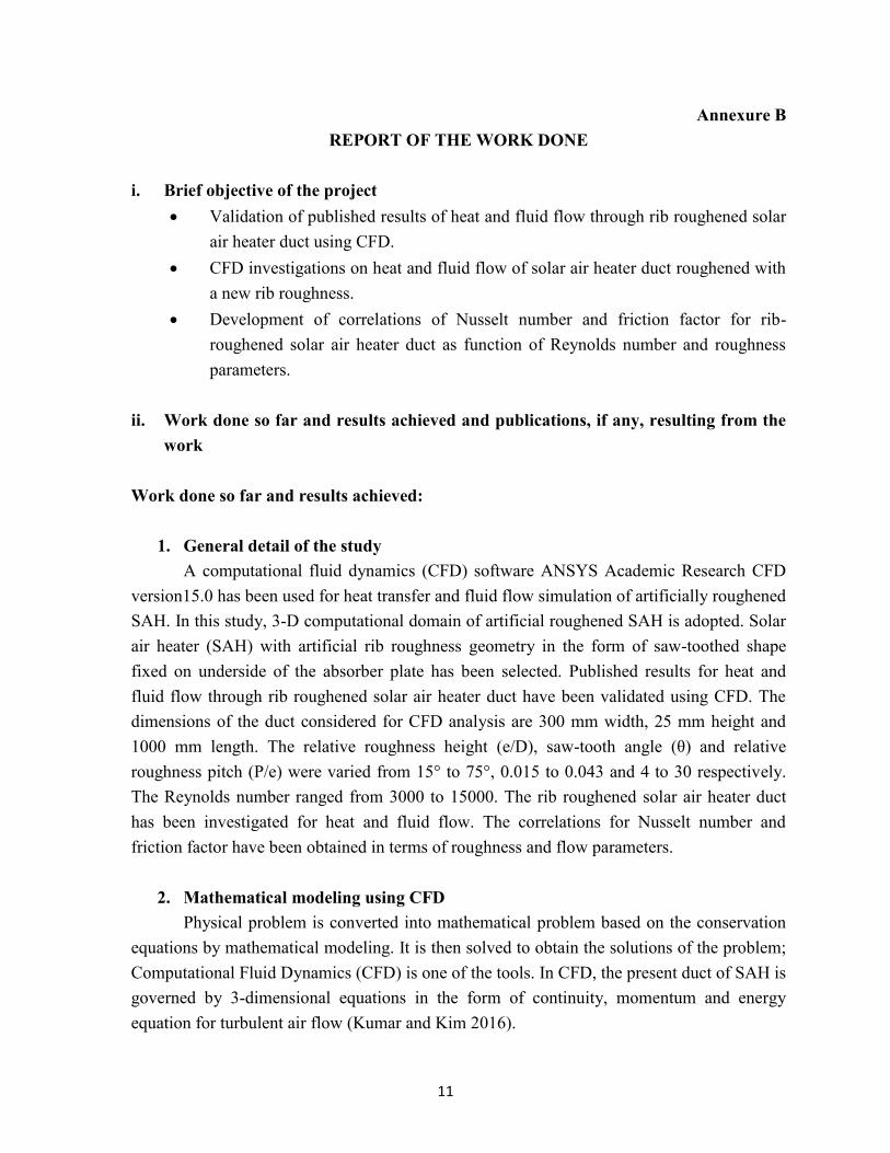
i. Brief objective of the project
Validation of published results of heat and fluid flow through rib roughened solar air heater duct using CFD.
CFD investigations on heat and fluid flow of solar air heater duct roughened with a new rib roughness.
Development of correlations of Nusselt number and friction factor for rib-roughened solar air heater duct as function of Reynolds number and roughness parameters.
ii. Work done so far and results achieved and publications, if any, resulting from the
work
Work done so far and results achieved:
1. General detail of the study A computational fluid dynamics (CFD) software ANSYS Academic Research CFD
version15.0 has been used for heat transfer and fluid flow simulation of artificially roughened SAH. In this study, 3-D computational domain of artificial roughened SAH is adopted. Solar air heater (SAH) with artificial rib roughness geometry in the form of saw-toothed shape fixed on underside of the absorber plate has been selected. Published results for heat and fluid flow through rib roughened solar air heater duct have been validated using CFD. The dimensions of the duct considered for CFD analysis are 300 mm width, 25 mm height and 1000 mm length. The relative roughness height (e/D), saw-tooth angle (θ) and relative roughness pitch (P/e) were varied from 15° to 75°, 0.015 to 0.043 and 4 to 30 respectively. The Reynolds number ranged from 3000 to 15000. The rib roughened solar air heater duct has been investigated for heat and fluid flow. The correlations for Nusselt number and friction factor have been obtained in terms of roughness and flow parameters.
2. Mathematical modeling using CFD Physical problem is converted into mathematical problem based on the conservation
equations by mathematical modeling. It is then solved to obtain the solutions of the problem; Computational Fluid Dynamics (CFD) is one of the tools. In CFD, the present duct of SAH is governed by 3-dimensional equations in the form of continuity, momentum and energy equation for turbulent air flow (Kumar and Kim 2016).
12
3. Review of literature
The conventional solar air heaters have airflow generally in turbulent flow region with Reynolds number between 3000 to 15000 [1]. These air heaters have low thermal efficiency due to development of laminar sub-layer in turbulent boundary layer on airflow side of the absorber plate [2]. The enhancement in thermal performance by breaking the laminar sub-layer by employing artificial rib roughness on the airflow side of absorber plate has widely been accepted as convenient and efficient method [3,4,5]. The enhancement of heat transfer in compact heat exchangers [6] and gas turbine cooling systems [7] is also commonly achieved with rib roughness.
A number of investigations using different rib roughness geometries for solar air heater duct have been reported in literature [8]. Simplest of the rib geometries are transverse [9], inclined [10], arc shape [11] and V-shape [12]. The inclined rib increase heat transfer coefficient more than the transverse rib because of secondary flow generation in addition to breaking laminar sub-layer. The friction factor decreases with reduction in angle of attack due to reduced form drag. V-shape rib causes further increase in heat transfer coefficient due to generation of two high heat transfer regions. V-down rib results in higher heat transfer coefficient than V-up rib for duct aspect ratio and Reynolds number range normally used in solar air heaters [13]. The friction factor of V-down rib was found to be less than V-up rib [14,15,16] but Karwa [17] reported otherwise. Multiple V-shape ribs have been reported to further enhance the Nusselt number [18]. Apart from simple rib geometries, effect of their discretization on thermal and hydraulic performance enhancement has also been reported [19, 20, 21]. Most of the studies mentioned above have used rib of circular cross-section except study on transverse rib of square cross-section by Karwa et al. [22] and chamfered cross-section by Bhagoria et al. [23].
Most of the studies on rib roughness of solar air heater duct have been carried experimentally and only a few studies using computational fluid dynamics have been reported [24-29]. Two-dimensional CFD analysis on rib roughened solar air heater duct using commercial software FLUENT 6.1 has been reported by Chaube et al. [30]. Heat transfer and fluid flow analysis have been done for five rib shapes viz. rectangular, square, chamfered, semicircular and circular rib. Shear stress transport k-ω turbulence model was selected for analysis based on the comparison with experimental results available in literature. The inter-rib Nusselt number, streamlines and velocity vectors have been plotted. Results have been obtained in-terms of Nusselt number, friction factor and performance index. Two-dimensional CFD analysis for wedge shaped transverse rib roughened solar air heater duct done using CFD software FLUENT was found to have good agreement with experimental results for Nusselt number [31]. Yadav and Bhagoria [27] conducted 2-D CFD
13
study using ANSYS FLUENT 12.1. From amongst the different turbulence models, the results obtained using Renormalization group (RNG) k-ε turbulence model were in good agreement with the Dittus-Boelter and Blasius empirical correlation. The effect of relative roughness height, relative roughness pitch and Reynolds number for transverse rib was investigated. The Nusselt number, friction factor and thermal enhancement factor were determined. Three-dimensional CFD investigation on rib roughened solar air heater duct using FLUENT 6.3.26 has been reported by Kumar and Saini [24] for arc-shaped rib roughness. Renormalization-group (RNG) k-ε turbulence model has been selected for analysis. The effect of geometrical rib parameters and flow Reynolds number on overall enhancement ratio has been determined. CFD simulation in 3D was performed for metal grit rib roughened solar air heater duct using CFD software FLUENT [25]. The investigation was done for different rib geometry parameters. The simulation was validated experimentally.
All the above studies have been conducted for ribs having uniform cross-section. Moving further from uniform cross-section ribs, in the present study an entirely new concept of non-uniform cross-section rib for solar air heater duct has been investigated. From the literature review, it is clear that no investigation has been carried out to study the effect of non-uniform rib cross-section on Nusselt number and friction factor of duct. It is expected that the non-uniform cross-section rib will break the laminar sub-layer as well as reduce eddy formation downstream of the rib thereby enhancing the heat transfer and reducing pumping power. In the present investigation, CFD analysis of rib roughened solar air heater duct has been carried out for transverse rib having non-uniform rib cross-section in the form of saw-tooth. For comparison transverse rib having uniform cross-section in the form of square, circular and trapezoidal have also been investigated. The effect of different cross-sections on Nusselt number and friction factor has been determined and discussed.
4. Validation of published results and selection of new geometry For validation of the published results and the selection of new rib-roughness
geometry, CFD analysis was carried out as described below: Description of Computational Model
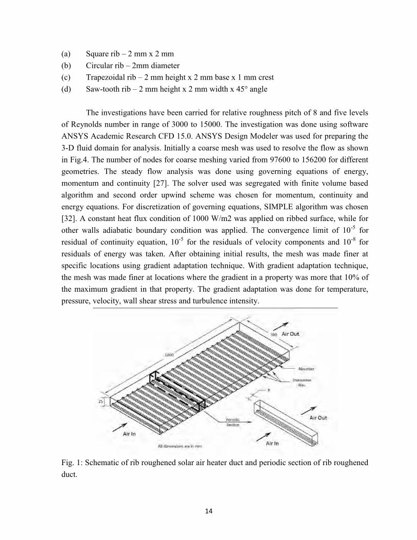
The transverse rib roughened solar air heater duct has been considered for CFD investigation (Fig.1). The flow cross-section of the duct is 300 mm x 25 mm and duct length is 1 m. One broad wall of the duct is heated with uniform heat flux of 1000 W/m2. This has been done to simulate conventional solar air heater, wherein a broad wall of duct acts as absorber of solar radiations. The rib roughness is employed in the duct on the heated wall for enhancing thermal performance by breaking the laminar sub-layer. Different cross-sections of rib taken up for investigation are shown in Fig. 2 and their detail is given below:
14
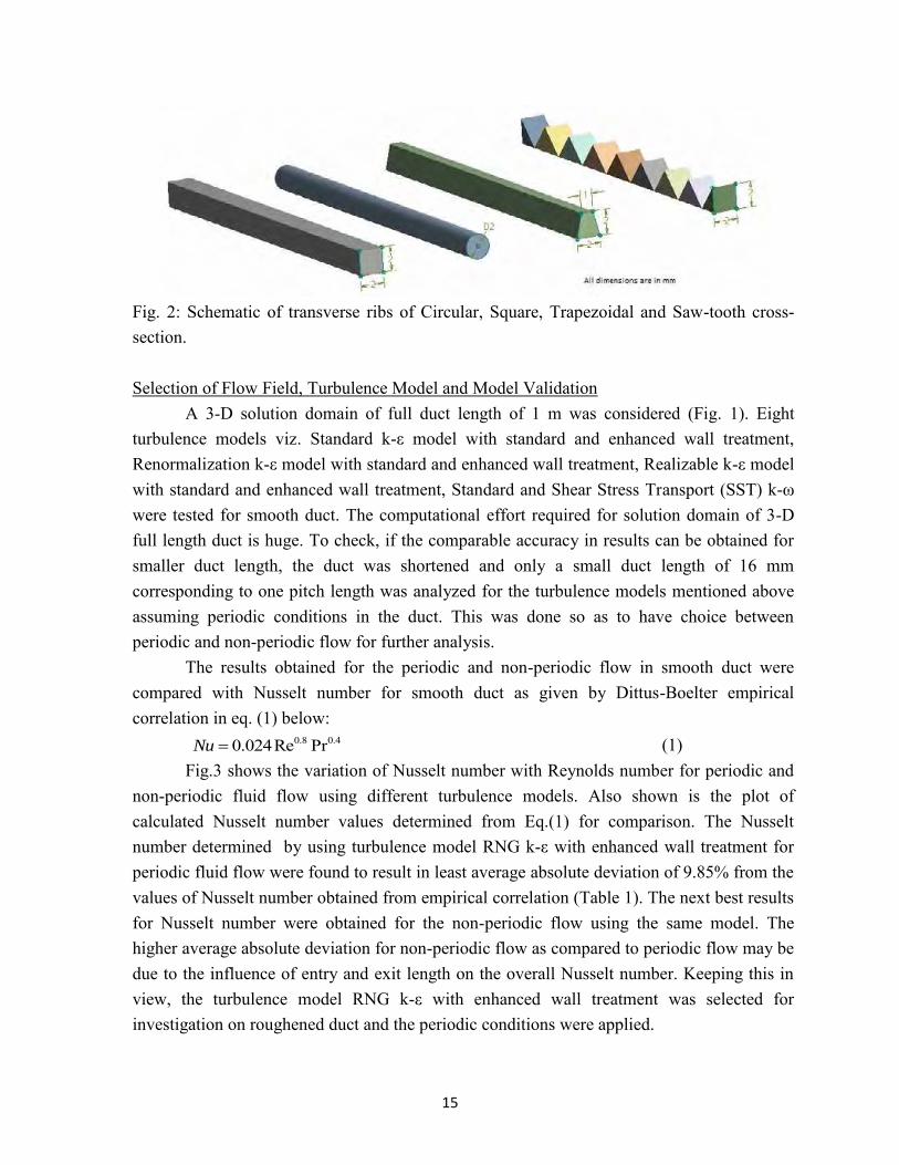
(a) Square rib – 2 mm x 2 mm (b) Circular rib – 2mm diameter (c) Trapezoidal rib – 2 mm height x 2 mm base x 1 mm crest (d) Saw-tooth rib – 2 mm height x 2 mm width x 45° angle
The investigations have been carried for relative roughness pitch of 8 and five levels of Reynolds number in range of 3000 to 15000. The investigation was done using software ANSYS Academic Research CFD 15.0. ANSYS Design Modeler was used for preparing the 3-D fluid domain for analysis. Initially a coarse mesh was used to resolve the flow as shown in Fig.4. The number of nodes for coarse meshing varied from 97600 to 156200 for different geometries. The steady flow analysis was done using governing equations of energy, momentum and continuity [27]. The solver used was segregated with finite volume based algorithm and second order upwind scheme was chosen for momentum, continuity and energy equations. For discretization of governing equations, SIMPLE algorithm was chosen [32]. A constant heat flux condition of 1000 W/m2 was applied on ribbed surface, while for other walls adiabatic boundary condition was applied. The convergence limit of 10-5 for residual of continuity equation, 10-5 for the residuals of velocity components and 10-8 for residuals of energy was taken. After obtaining initial results, the mesh was made finer at specific locations using gradient adaptation technique. With gradient adaptation technique, the mesh was made finer at locations where the gradient in a property was more that 10% of the maximum gradient in that property. The gradient adaptation was done for temperature, pressure, velocity, wall shear stress and turbulence intensity.
Fig. 1: Schematic of rib roughened solar air heater duct and periodic section of rib roughened duct.
15
Fig. 2: Schematic of transverse ribs of Circular, Square, Trapezoidal and Saw-tooth cross-section. Selection of Flow Field, Turbulence Model and Model Validation
A 3-D solution domain of full duct length of 1 m was considered (Fig. 1). Eight turbulence models viz. Standard k-ε model with standard and enhanced wall treatment, Renormalization k-ε model with standard and enhanced wall treatment, Realizable k-ε model with standard and enhanced wall treatment, Standard and Shear Stress Transport (SST) k-ω were tested for smooth duct. The computational effort required for solution domain of 3-D full length duct is huge. To check, if the comparable accuracy in results can be obtained for smaller duct length, the duct was shortened and only a small duct length of 16 mm corresponding to one pitch length was analyzed for the turbulence models mentioned above assuming periodic conditions in the duct. This was done so as to have choice between periodic and non-periodic flow for further analysis.
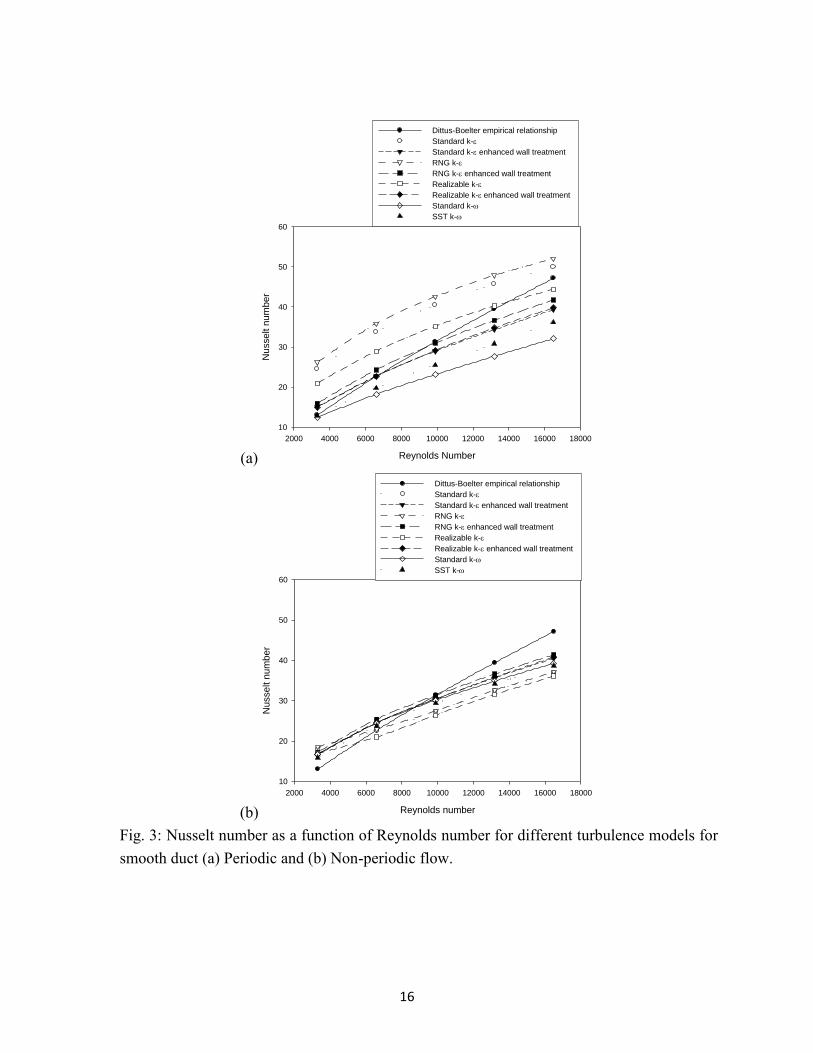
The results obtained for the periodic and non-periodic flow in smooth duct were compared with Nusselt number for smooth duct as given by Dittus-Boelter empirical correlation in eq. (1) below: 4.08.0 PrRe024.0Nu (1)
Fig.3 shows the variation of Nusselt number with Reynolds number for periodic and non-periodic fluid flow using different turbulence models. Also shown is the plot of calculated Nusselt number values determined from Eq.(1) for comparison. The Nusselt number determined by using turbulence model RNG k-ε with enhanced wall treatment for periodic fluid flow were found to result in least average absolute deviation of 9.85% from the values of Nusselt number obtained from empirical correlation (Table 1). The next best results for Nusselt number were obtained for the non-periodic flow using the same model. The higher average absolute deviation for non-periodic flow as compared to periodic flow may be due to the influence of entry and exit length on the overall Nusselt number. Keeping this in view, the turbulence model RNG k-ε with enhanced wall treatment was selected for investigation on roughened duct and the periodic conditions were applied.
16
(a) Reynolds Number
2000 4000 6000 8000 10000 12000 14000 16000 18000
Nu
sse
lt n
um
be
r
10
20
30
40
50
60
Dittus-Boelter empirical relationship
Standard k-
Standard k- enhanced wall treatment
RNG k-
RNG k- enhanced wall treatment
Realizable k-
Realizable k-enhanced wall treatment
Standard k-
SST k-
(b) Reynolds number
2000 4000 6000 8000 10000 12000 14000 16000 18000
Nusse
lt n
um
ber
10
20
30
40
50
60
Dittus-Boelter empirical relationship
Standard k-
Standard k- enhanced wall treatment
RNG k-
RNG k- enhanced wall treatment
Realizable k-
Realizable k- enhanced wall treatment
Standard k-
SST k-
Fig. 3: Nusselt number as a function of Reynolds number for different turbulence models for smooth duct (a) Periodic and (b) Non-periodic flow.
17
Table 1: Average absolute deviation of Nusselt number obtained using different turbulence models for periodic and non-periodic flow in smooth duct. Flow type
Average absolute deviation (%) Standard k-ε with standard wall function
Standard k-ε with enhanced wall treatment
RNG k-ε with standard wall functions
RNG k-ε with enhanced wall functions
Realizable k-ε with standard wall functions
Realizable k-ε with enhanced wall treatment
Standard k-ω
SST k-ω
Periodic flow
37.89 10.54
45.45
9.85
21.77
9.94
22.45
15.56
Non-periodic flow
18.54 12.56
18.91
12.75
19.33
12.50
13.73
12.87
Grid Independence Test
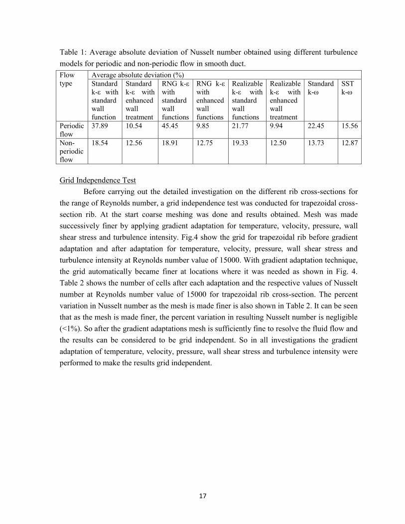
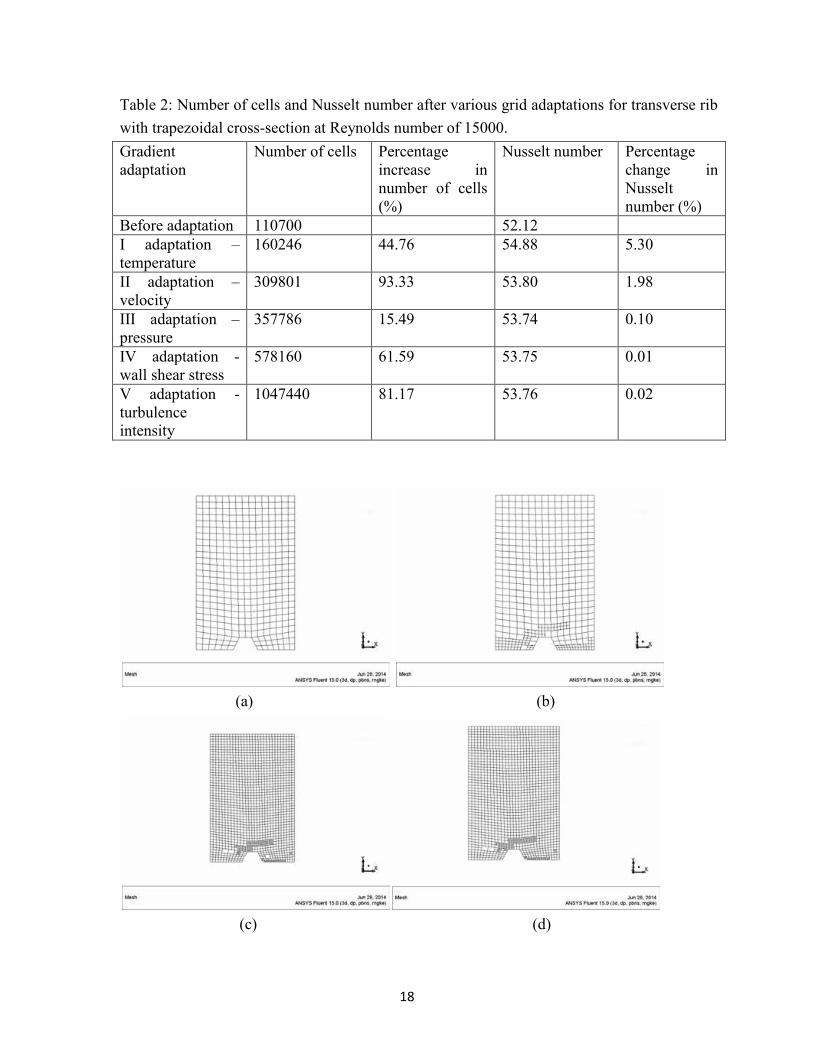
Before carrying out the detailed investigation on the different rib cross-sections for the range of Reynolds number, a grid independence test was conducted for trapezoidal cross-section rib. At the start coarse meshing was done and results obtained. Mesh was made successively finer by applying gradient adaptation for temperature, velocity, pressure, wall shear stress and turbulence intensity. Fig.4 show the grid for trapezoidal rib before gradient adaptation and after adaptation for temperature, velocity, pressure, wall shear stress and turbulence intensity at Reynolds number value of 15000. With gradient adaptation technique, the grid automatically became finer at locations where it was needed as shown in Fig. 4. Table 2 shows the number of cells after each adaptation and the respective values of Nusselt number at Reynolds number value of 15000 for trapezoidal rib cross-section. The percent variation in Nusselt number as the mesh is made finer is also shown in Table 2. It can be seen that as the mesh is made finer, the percent variation in resulting Nusselt number is negligible (<1%). So after the gradient adaptations mesh is sufficiently fine to resolve the fluid flow and the results can be considered to be grid independent. So in all investigations the gradient adaptation of temperature, velocity, pressure, wall shear stress and turbulence intensity were performed to make the results grid independent.
18
Table 2: Number of cells and Nusselt number after various grid adaptations for transverse rib with trapezoidal cross-section at Reynolds number of 15000. Gradient adaptation
Number of cells Percentage increase in number of cells (%)
Nusselt number Percentage change in Nusselt number (%)
Before adaptation 110700 52.12 I adaptation – temperature
160246 44.76 54.88 5.30
II adaptation –velocity
309801 93.33 53.80 1.98
III adaptation –pressure
357786 15.49 53.74 0.10
IV adaptation - wall shear stress
578160 61.59 53.75 0.01
V adaptation - turbulence intensity
1047440 81.17 53.76 0.02
(a) (b)
(c) (d)
19
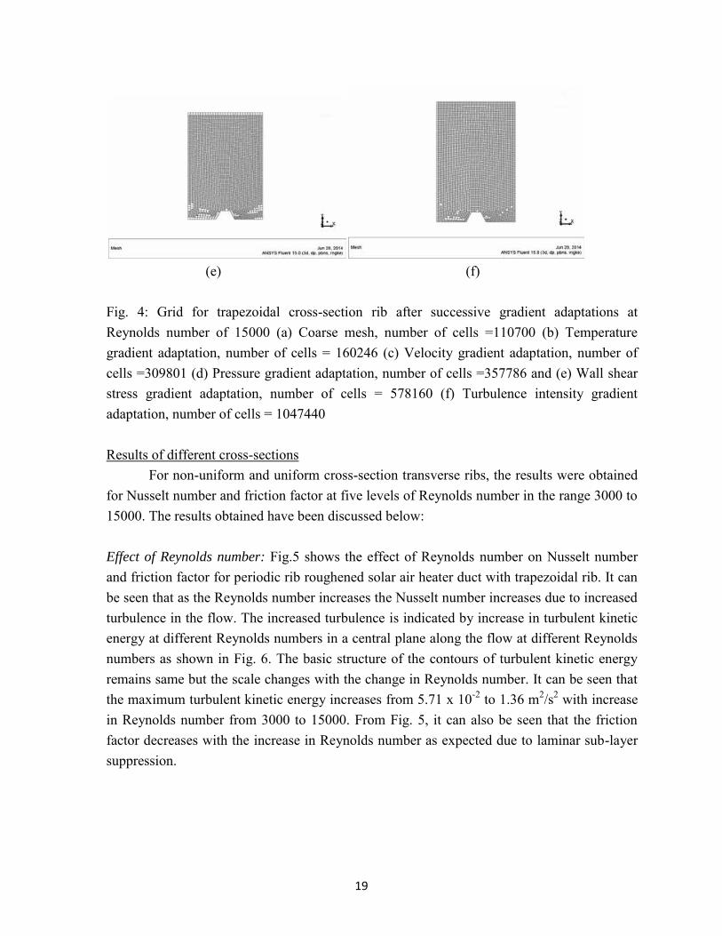
(e) (f) Fig. 4: Grid for trapezoidal cross-section rib after successive gradient adaptations at Reynolds number of 15000 (a) Coarse mesh, number of cells =110700 (b) Temperature gradient adaptation, number of cells = 160246 (c) Velocity gradient adaptation, number of cells =309801 (d) Pressure gradient adaptation, number of cells =357786 and (e) Wall shear stress gradient adaptation, number of cells = 578160 (f) Turbulence intensity gradient adaptation, number of cells = 1047440 Results of different cross-sections
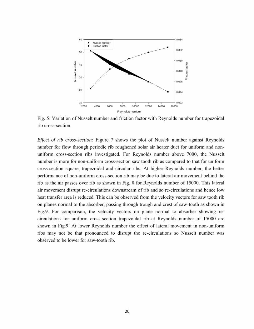
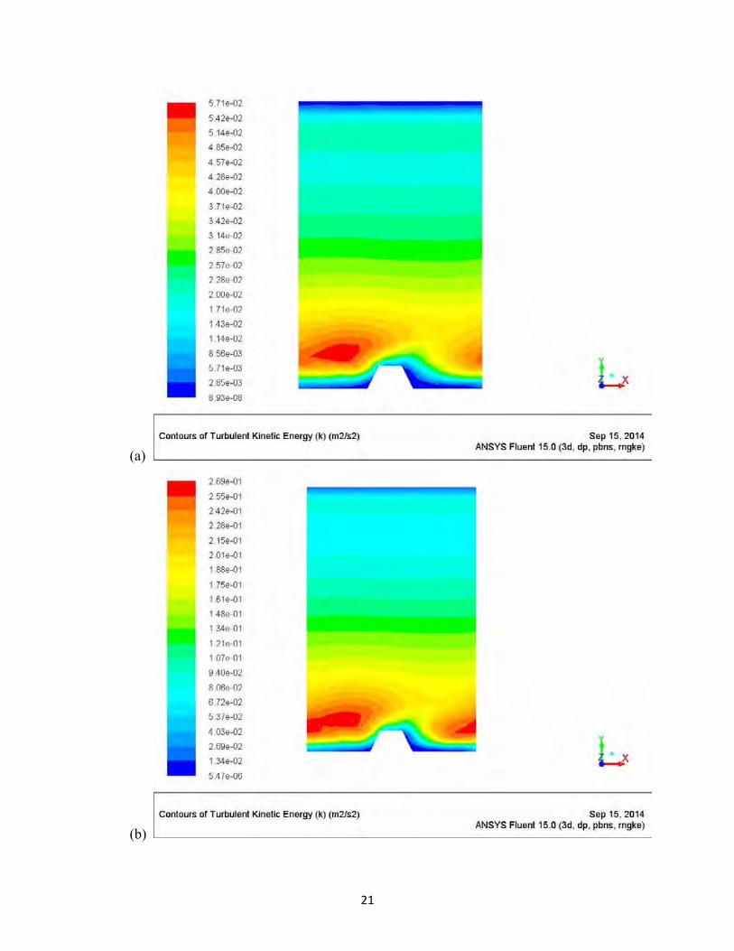
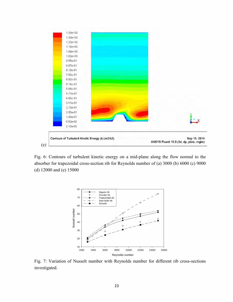
For non-uniform and uniform cross-section transverse ribs, the results were obtained for Nusselt number and friction factor at five levels of Reynolds number in the range 3000 to 15000. The results obtained have been discussed below: Effect of Reynolds number: Fig.5 shows the effect of Reynolds number on Nusselt number and friction factor for periodic rib roughened solar air heater duct with trapezoidal rib. It can be seen that as the Reynolds number increases the Nusselt number increases due to increased turbulence in the flow. The increased turbulence is indicated by increase in turbulent kinetic energy at different Reynolds numbers in a central plane along the flow at different Reynolds numbers as shown in Fig. 6. The basic structure of the contours of turbulent kinetic energy remains same but the scale changes with the change in Reynolds number. It can be seen that the maximum turbulent kinetic energy increases from 5.71 x 10⁻² to 1.36 m2/s2 with increase in Reynolds number from 3000 to 15000. From Fig. 5, it can also be seen that the friction factor decreases with the increase in Reynolds number as expected due to laminar sub-layer suppression.
20
Reynolds number
2000 4000 6000 8000 10000 12000 14000 16000
Nusse
lt n
um
ber
10
20
30
40
50
60
Frictio
n fa
cto
r
0.022
0.024
0.026
0.028
0.030
0.032
0.034
Nusselt number
Friction factor
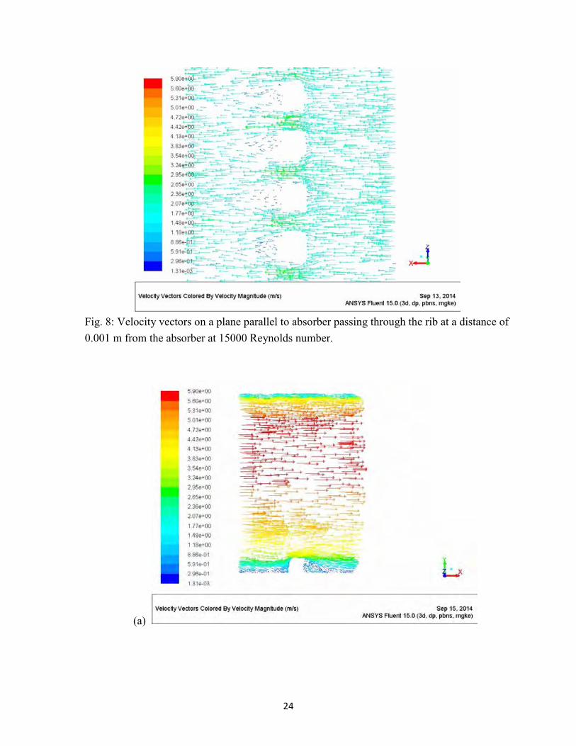
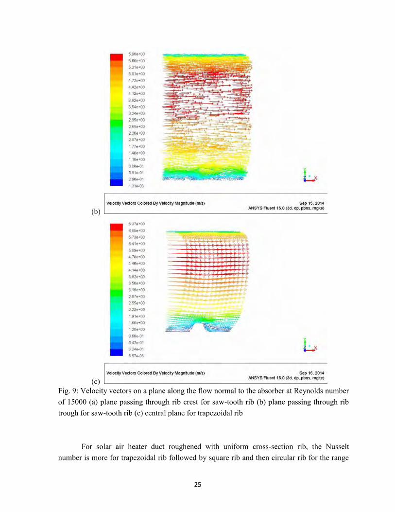
Fig. 5: Variation of Nusselt number and friction factor with Reynolds number for trapezoidal rib cross-section. Effect of rib cross-section: Figure 7 shows the plot of Nusselt number against Reynolds number for flow through periodic rib roughened solar air heater duct for uniform and non-uniform cross-section ribs investigated. For Reynolds number above 7000, the Nusselt number is more for non-uniform cross-section saw tooth rib as compared to that for uniform cross-section square, trapezoidal and circular ribs. At higher Reynolds number, the better performance of non-uniform cross-section rib may be due to lateral air movement behind the rib as the air passes over rib as shown in Fig. 8 for Reynolds number of 15000. This lateral air movement disrupt re-circulations downstream of rib and so re-circulations and hence low heat transfer area is reduced. This can be observed from the velocity vectors for saw tooth rib on planes normal to the absorber, passing through trough and crest of saw-tooth as shown in Fig.9. For comparison, the velocity vectors on plane normal to absorber showing re-circulations for uniform cross-section trapezoidal rib at Reynolds number of 15000 are shown in Fig.9. At lower Reynolds number the effect of lateral movement in non-uniform ribs may not be that pronounced to disrupt the re-circulations so Nusselt number was observed to be lower for saw-tooth rib.
21
(a)
(b)
22
(c)
(d)
23
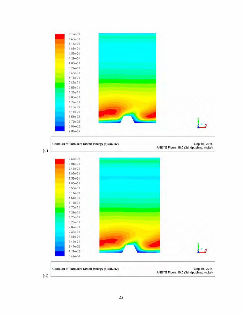
(e) Fig. 6: Contours of turbulent kinetic energy on a mid-plane along the flow normal to the absorber for trapezoidal cross-section rib for Reynolds number of (a) 3000 (b) 6000 (c) 9000 (d) 12000 and (e) 15000
Reynolds number
2000 4000 6000 8000 10000 12000 14000 16000
Nusse
lt n
um
ber
10
20
30
40
50
60
70
80
Sqaure rib
Circular rib
Trapezoidal rib
Saw-tooth rib
Smooth
Fig. 7: Variation of Nusselt number with Reynolds number for different rib cross-sections investigated.
24
Fig. 8: Velocity vectors on a plane parallel to absorber passing through the rib at a distance of 0.001 m from the absorber at 15000 Reynolds number.
(a)
25
(b)
(c) Fig. 9: Velocity vectors on a plane along the flow normal to the absorber at Reynolds number of 15000 (a) plane passing through rib crest for saw-tooth rib (b) plane passing through rib trough for saw-tooth rib (c) central plane for trapezoidal rib
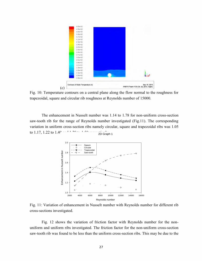
For solar air heater duct roughened with uniform cross-section rib, the Nusselt number is more for trapezoidal rib followed by square rib and then circular rib for the range

26
of Reynolds number investigated. This is also indicated by the temperature contours in the central plane normal to the absorber as shown in Fig. 10. It can be seen from the contours that the higher temperature can be observed for larger distance normal to absorber away from the rib in case of trapezoidal rib followed by square rib and then trapezoidal rib. The maximum temperature shown in the temperature contours is 347 K for trapezoidal rib, 354 K for square rib and 465 K for circular rib. This also indicates lesser intermixing /turbulence of flowing air causing greater air temperature variation for circular rib as compared to square rib and trapezoidal rib.
(a)
(b)
27
(c) Fig. 10: Temperature contours on a central plane along the flow normal to the roughness for trapezoidal, square and circular rib roughness at Reynolds number of 15000.
The enhancement in Nusselt number was 1.14 to 1.78 for non-uniform cross-section
saw-tooth rib for the range of Reynolds number investigated (Fig.11). The corresponding variation in uniform cross-section ribs namely circular, square and trapezoidal ribs was 1.05 to 1.17, 1.22 to 1.40 and 1.28 to 1.50 respectively.
2D Graph 1
Reynolds number
2000 4000 6000 8000 10000 12000 14000 16000
En
ha
nce
men
t in
Nu
sse
lt n
um
be
r
1.0
1.2
1.4
1.6
1.8
2.0
Sqaure
Circular
Trapezoidal
Saw-tooth
Fig. 11: Variation of enhancement in Nusselt number with Reynolds number for different rib cross-sections investigated.
Fig. 12 shows the variation of friction factor with Reynolds number for the non-uniform and uniform ribs investigated. The friction factor for the non-uniform cross-section saw-tooth rib was found to be less than the uniform cross-section ribs. This may be due to the

28
reduction in re-circulations downstream of rib in saw-tooth rib as can be seen from the velocity vectors on planes normal to the absorber passing through crest and trough of the rib (Fig.9). For uniform cross-section rib, the friction factor for square rib was found to be maximum followed by trapezoidal and circular rib. This may be due to the edges of the square rib that interfere with the fluid flow causing higher pressure drop and hence friction factor.
The enhancement in friction factor varied from 1.60 to 2.49, 2.43 to 3.40, 2.64 to 3.74 and 2.59 to 3.58 respectively for saw-tooth rib, circular rib, square rib and trapezoidal ribs for the range of Reynolds number investigated (Fig.13).
Reynolds number
2000 4000 6000 8000 10000 12000 14000 16000
Frictio
n fa
cto
r
0.005
0.010
0.015
0.020
0.025
0.030
0.035Sqaure rib
Circular rib
Trapezoidal rib
Saw-tooth rib
Smooth
Fig. 12: Variation of friction factor with Reynolds number for different rib cross-sections investigated.
2D Graph 2
Reynolds number
2000 4000 6000 8000 10000 12000 14000 16000
Enhancem
ent in
friction facto
r
1.0
1.5
2.0
2.5
3.0
3.5
4.0
Sqaure
Circular
Trapezoidal
Saw-tooth
Fig. 13: Variation of enhancement in friction factor with Reynolds number for different rib cross-sections investigated.

29
Comparison of results of present CFD study and published results
The Nusselt number and friction factor were determined for the circular rib using Ansys CFD. These results were compared with the results obtained for experimental investigation by Gupta et al. (1993) for transverse circular rib in rectangular duct.
Fig. 14 and 15 shows the comparative Nusselt number and friction factor as a
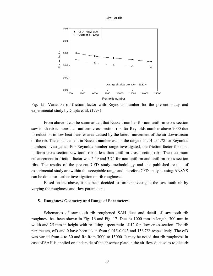
function of Reynolds number, for the present CFD study of circular rib and the experimental study by Gupta et al. (1993). It can be seen that the values of Nusselt number and friction factor for the two studies are very close. The average absolute deviation for the Nusselt number is 14.02% and for friction factor is 25.82%, which are within the acceptable range.
Hence it can be concluded that the CFD analysis can be used to predict the
performance of rib roughened rectangular duct.
Circular rib
Reynolds number
2000 4000 6000 8000 10000 12000 14000 16000
Nusselt n
um
ber
0
20
40
60
80
100
CFD - Ansys 15.0
Gupta et al. (1993)
Average absolute deviation = 14.02%
Fig. 14: Variation of Nusselt number with Reynolds number for the present study and experimental study by Gupta et al. (1993)
30
Circular rib
Reynolds number
2000 4000 6000 8000 10000 12000 14000 16000
Friction facto
r
0.00
0.01
0.02
0.03
0.04
0.05
CFD - Ansys 15.0
Gupta et al. (1993)
Average absolute deviation = 25.82%
Fig. 15: Variation of friction factor with Reynolds number for the present study and experimental study by Gupta et al. (1993)
From above it can be summarized that Nusselt number for non-uniform cross-section saw-tooth rib is more than uniform cross-section ribs for Reynolds number above 7000 due to reduction in low heat transfer area caused by the lateral movement of the air downstream of the rib. The enhancement in Nusselt number was in the range of 1.14 to 1.78 for Reynolds numbers investigated. For Reynolds number range investigated, the friction factor for non-uniform cross-section saw-tooth rib is less than uniform cross-section ribs. The maximum enhancement in friction factor was 2.49 and 3.74 for non-uniform and uniform cross-section ribs. The results of the present CFD study methodology and the published results of experimental study are within the acceptable range and therefore CFD analysis using ANSYS can be done for further investigation on rib roughness.
Based on the above, it has been decided to further investigate the saw-tooth rib by varying the roughness and flow parameters.
5. Roughness Geometry and Range of Parameters Schematics of saw-tooth rib roughened SAH duct and detail of saw-tooth rib
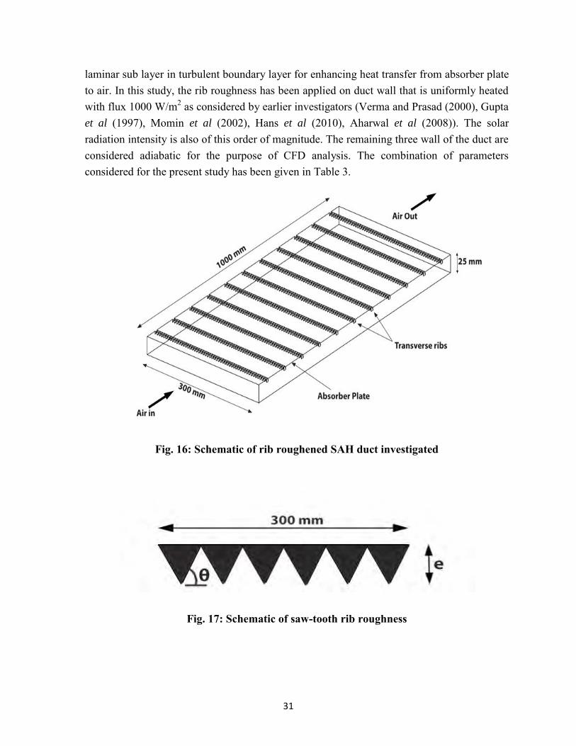
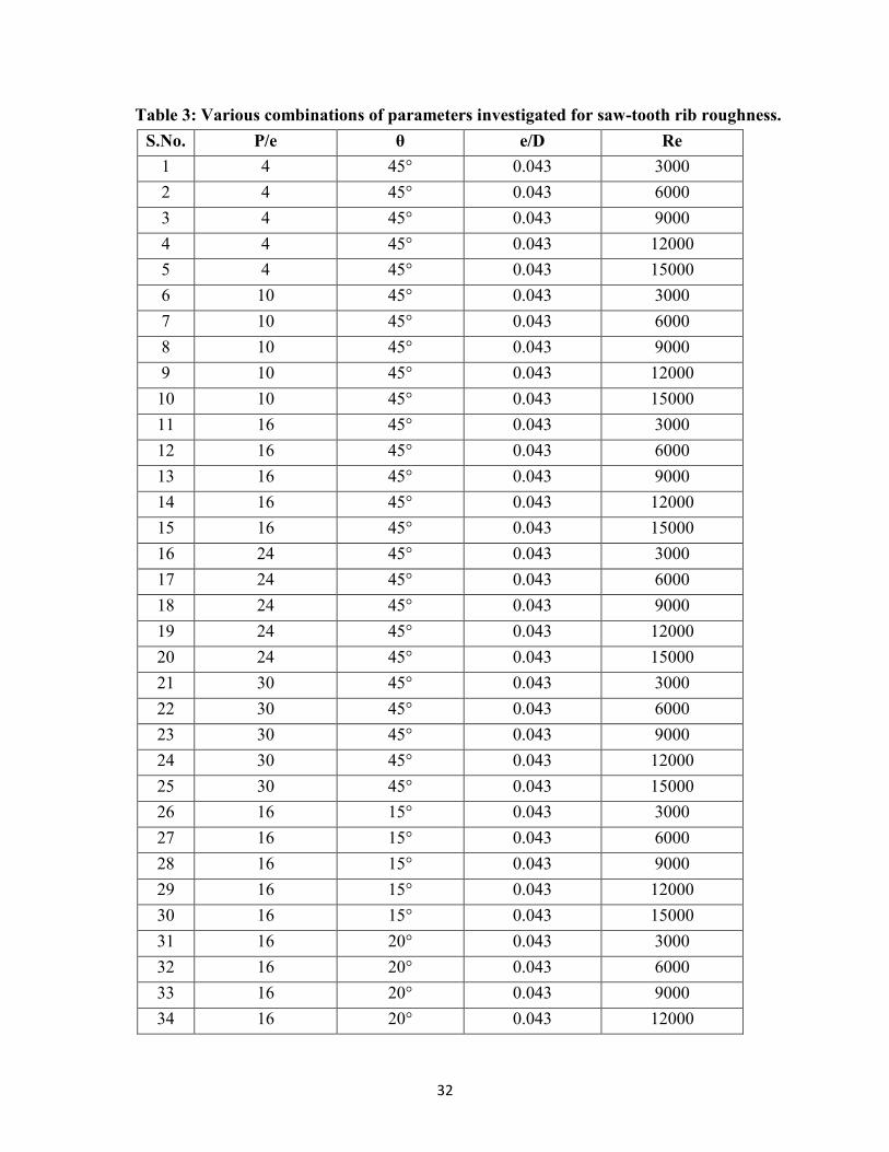
roughness has been shown in Fig. 16 and Fig. 17. Duct is 1000 mm in length, 300 mm in width and 25 mm in height with resulting aspect ratio of 12 for flow cross-section. The rib parameters, e/D and θ have been taken from 0.015-0.043 and 15°-75° respectively. The e/D was varied from 4 to 30 and Re from 3000 to 15000. It may be noted that rib roughness in case of SAH is applied on underside of the absorber plate in the air flow duct so as to disturb
31
laminar sub layer in turbulent boundary layer for enhancing heat transfer from absorber plate to air. In this study, the rib roughness has been applied on duct wall that is uniformly heated with flux 1000 W/m2 as considered by earlier investigators (Verma and Prasad (2000), Gupta et al (1997), Momin et al (2002), Hans et al (2010), Aharwal et al (2008)). The solar radiation intensity is also of this order of magnitude. The remaining three wall of the duct are considered adiabatic for the purpose of CFD analysis. The combination of parameters considered for the present study has been given in Table 3.
Fig. 16: Schematic of rib roughened SAH duct investigated
Fig. 17: Schematic of saw-tooth rib roughness
32
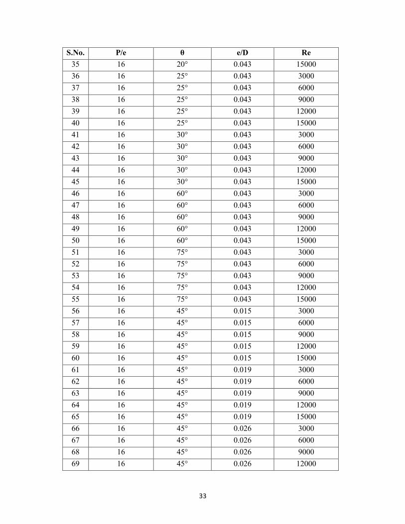
Table 3: Various combinations of parameters investigated for saw-tooth rib roughness. S.No. P/e θ e/D Re
1 4 45° 0.043 3000 2 4 45° 0.043 6000 3 4 45° 0.043 9000 4 4 45° 0.043 12000 5 4 45° 0.043 15000 6 10 45° 0.043 3000 7 10 45° 0.043 6000 8 10 45° 0.043 9000 9 10 45° 0.043 12000 10 10 45° 0.043 15000 11 16 45° 0.043 3000 12 16 45° 0.043 6000 13 16 45° 0.043 9000 14 16 45° 0.043 12000 15 16 45° 0.043 15000 16 24 45° 0.043 3000 17 24 45° 0.043 6000 18 24 45° 0.043 9000 19 24 45° 0.043 12000 20 24 45° 0.043 15000 21 30 45° 0.043 3000 22 30 45° 0.043 6000 23 30 45° 0.043 9000 24 30 45° 0.043 12000 25 30 45° 0.043 15000 26 16 15° 0.043 3000 27 16 15° 0.043 6000 28 16 15° 0.043 9000 29 16 15° 0.043 12000 30 16 15° 0.043 15000 31 16 20° 0.043 3000 32 16 20° 0.043 6000 33 16 20° 0.043 9000 34 16 20° 0.043 12000
33
S.No. P/e θ e/D Re 35 16 20° 0.043 15000 36 16 25° 0.043 3000 37 16 25° 0.043 6000 38 16 25° 0.043 9000 39 16 25° 0.043 12000 40 16 25° 0.043 15000 41 16 30° 0.043 3000 42 16 30° 0.043 6000 43 16 30° 0.043 9000 44 16 30° 0.043 12000 45 16 30° 0.043 15000 46 16 60° 0.043 3000 47 16 60° 0.043 6000 48 16 60° 0.043 9000 49 16 60° 0.043 12000 50 16 60° 0.043 15000 51 16 75° 0.043 3000 52 16 75° 0.043 6000 53 16 75° 0.043 9000 54 16 75° 0.043 12000 55 16 75° 0.043 15000 56 16 45° 0.015 3000 57 16 45° 0.015 6000 58 16 45° 0.015 9000 59 16 45° 0.015 12000 60 16 45° 0.015 15000 61 16 45° 0.019 3000 62 16 45° 0.019 6000 63 16 45° 0.019 9000 64 16 45° 0.019 12000 65 16 45° 0.019 15000 66 16 45° 0.026 3000 67 16 45° 0.026 6000 68 16 45° 0.026 9000 69 16 45° 0.026 12000
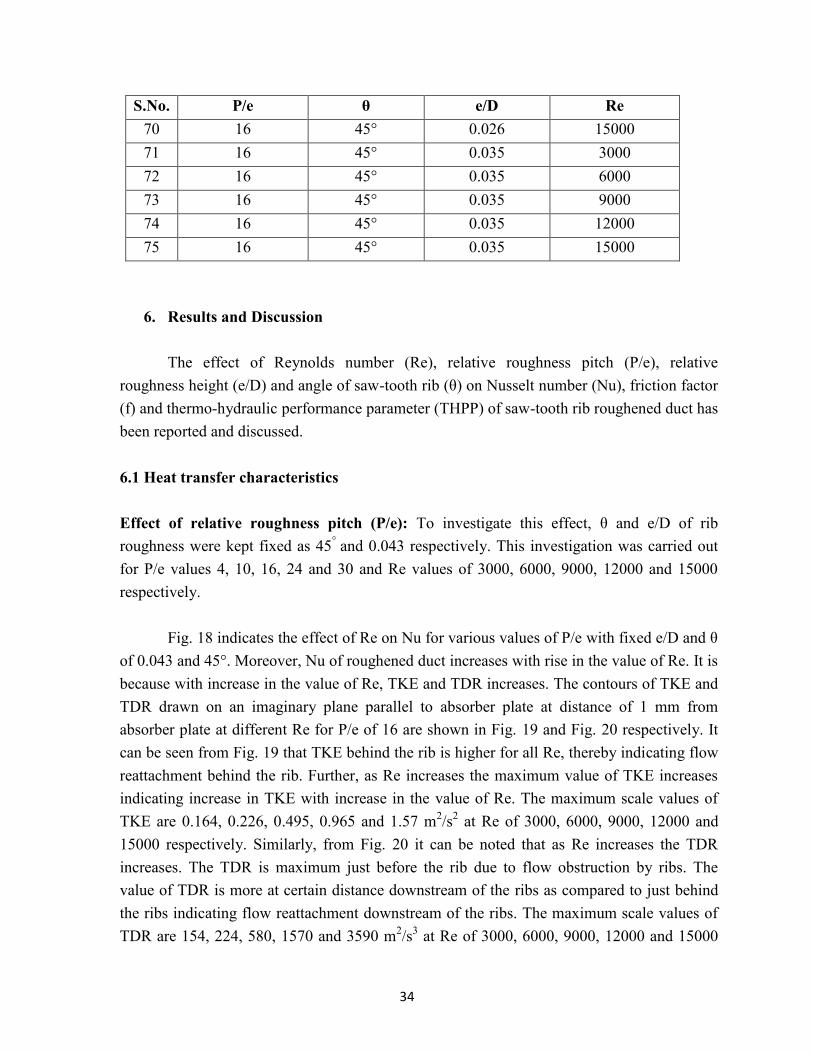
34
S.No. P/e θ e/D Re 70 16 45° 0.026 15000 71 16 45° 0.035 3000 72 16 45° 0.035 6000 73 16 45° 0.035 9000 74 16 45° 0.035 12000 75 16 45° 0.035 15000
6. Results and Discussion The effect of Reynolds number (Re), relative roughness pitch (P/e), relative
roughness height (e/D) and angle of saw-tooth rib (θ) on Nusselt number (Nu), friction factor (f) and thermo-hydraulic performance parameter (THPP) of saw-tooth rib roughened duct has been reported and discussed. 6.1 Heat transfer characteristics Effect of relative roughness pitch (P/e): To investigate this effect, θ and e/D of rib roughness were kept fixed as 45° and 0.043 respectively. This investigation was carried out for P/e values 4, 10, 16, 24 and 30 and Re values of 3000, 6000, 9000, 12000 and 15000 respectively.
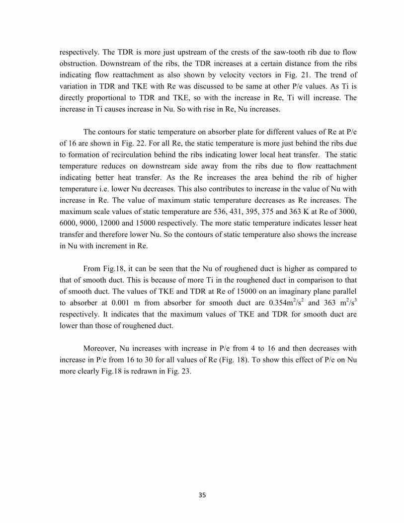
Fig. 18 indicates the effect of Re on Nu for various values of P/e with fixed e/D and θ
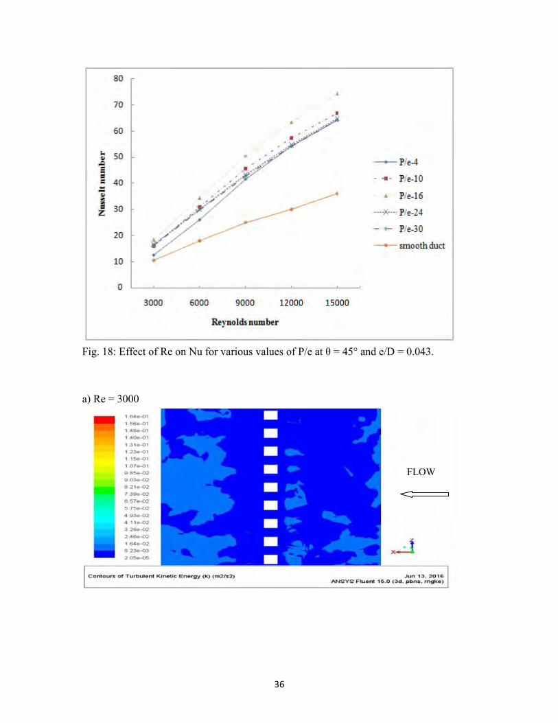
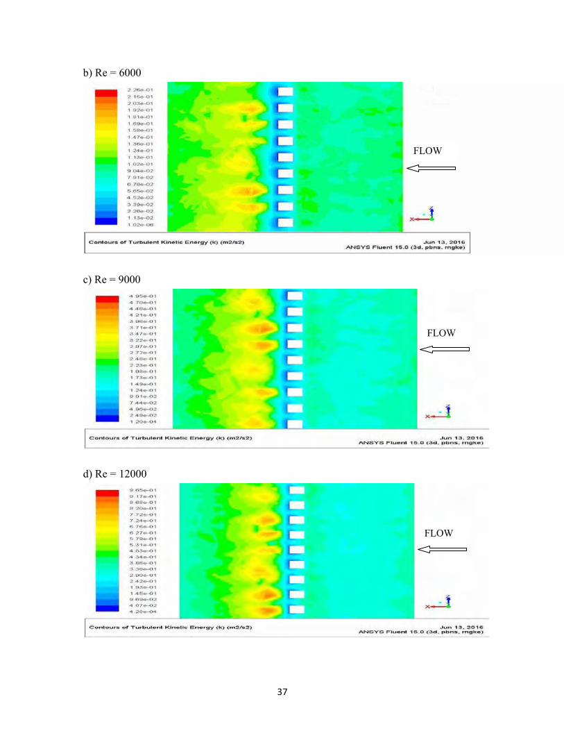
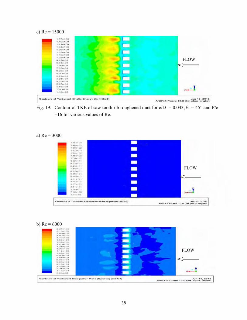
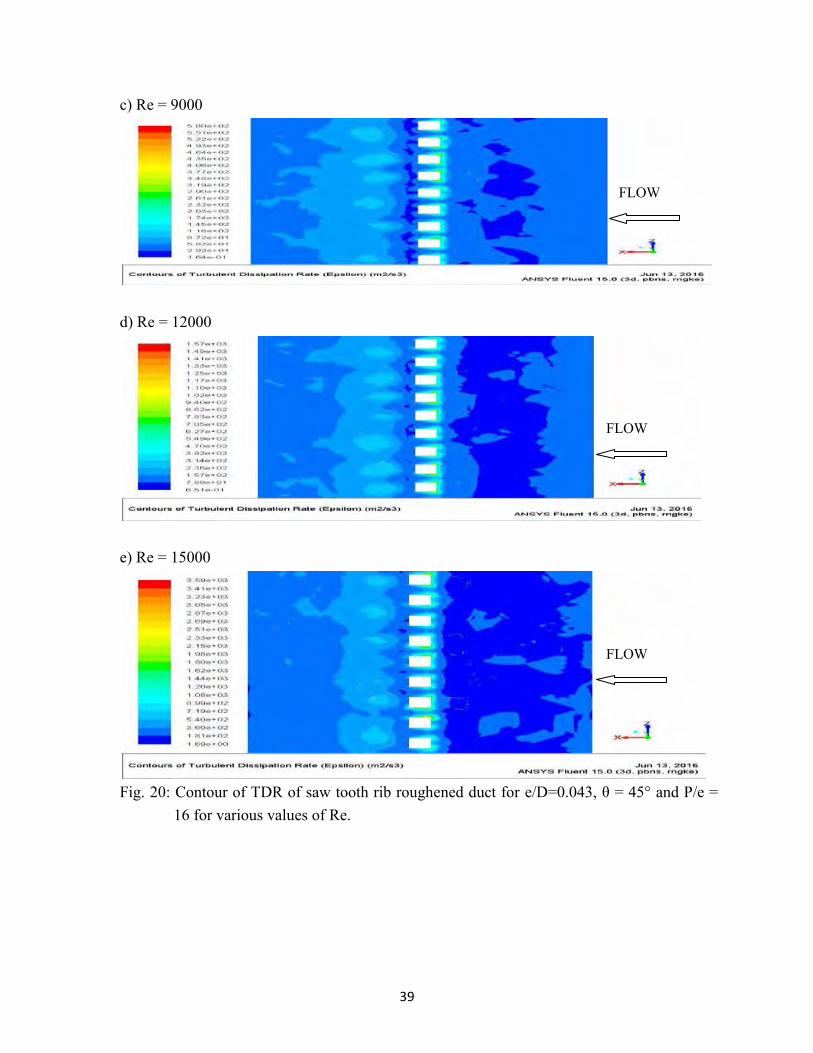
of 0.043 and 45°. Moreover, Nu of roughened duct increases with rise in the value of Re. It is because with increase in the value of Re, TKE and TDR increases. The contours of TKE and TDR drawn on an imaginary plane parallel to absorber plate at distance of 1 mm from absorber plate at different Re for P/e of 16 are shown in Fig. 19 and Fig. 20 respectively. It can be seen from Fig. 19 that TKE behind the rib is higher for all Re, thereby indicating flow reattachment behind the rib. Further, as Re increases the maximum value of TKE increases indicating increase in TKE with increase in the value of Re. The maximum scale values of TKE are 0.164, 0.226, 0.495, 0.965 and 1.57 m2/s2 at Re of 3000, 6000, 9000, 12000 and 15000 respectively. Similarly, from Fig. 20 it can be noted that as Re increases the TDR increases. The TDR is maximum just before the rib due to flow obstruction by ribs. The value of TDR is more at certain distance downstream of the ribs as compared to just behind the ribs indicating flow reattachment downstream of the ribs. The maximum scale values of TDR are 154, 224, 580, 1570 and 3590 m2/s3 at Re of 3000, 6000, 9000, 12000 and 15000
35
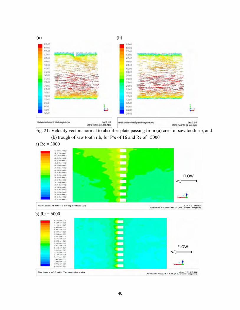
respectively. The TDR is more just upstream of the crests of the saw-tooth rib due to flow obstruction. Downstream of the ribs, the TDR increases at a certain distance from the ribs indicating flow reattachment as also shown by velocity vectors in Fig. 21. The trend of variation in TDR and TKE with Re was discussed to be same at other P/e values. As Ti is directly proportional to TDR and TKE, so with the increase in Re, Ti will increase. The increase in Ti causes increase in Nu. So with rise in Re, Nu increases.
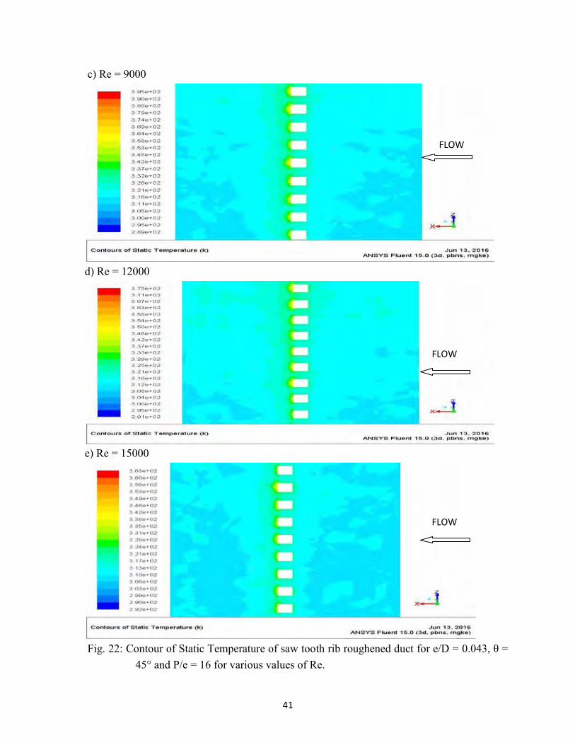
The contours for static temperature on absorber plate for different values of Re at P/e
of 16 are shown in Fig. 22. For all Re, the static temperature is more just behind the ribs due to formation of recirculation behind the ribs indicating lower local heat transfer. The static temperature reduces on downstream side away from the ribs due to flow reattachment indicating better heat transfer. As the Re increases the area behind the rib of higher temperature i.e. lower Nu decreases. This also contributes to increase in the value of Nu with increase in Re. The value of maximum static temperature decreases as Re increases. The maximum scale values of static temperature are 536, 431, 395, 375 and 363 K at Re of 3000, 6000, 9000, 12000 and 15000 respectively. The more static temperature indicates lesser heat transfer and therefore lower Nu. So the contours of static temperature also shows the increase in Nu with increment in Re.
From Fig.18, it can be seen that the Nu of roughened duct is higher as compared to
that of smooth duct. This is because of more Ti in the roughened duct in comparison to that of smooth duct. The values of TKE and TDR at Re of 15000 on an imaginary plane parallel to absorber at 0.001 m from absorber for smooth duct are 0.354m2/s2 and 363 m2/s3 respectively. It indicates that the maximum values of TKE and TDR for smooth duct are lower than those of roughened duct.
Moreover, Nu increases with increase in P/e from 4 to 16 and then decreases with
increase in P/e from 16 to 30 for all values of Re (Fig. 18). To show this effect of P/e on Nu more clearly Fig.18 is redrawn in Fig. 23.
36
Fig. 18: Effect of Re on Nu for various values of P/e at θ = 45° and e/D = 0.043. a) Re = 3000
FLOW
37
b) Re = 6000
c) Re = 9000
d) Re = 12000
FLOW
FLOW
FLOW
38
e) Re = 15000
Fig. 19: Contour of TKE of saw tooth rib roughened duct for e/D = 0.043, θ = 45° and P/e
=16 for various values of Re. a) Re = 3000
b) Re = 6000
FLOW
FLOW
FLOW
39
c) Re = 9000
d) Re = 12000
e) Re = 15000
Fig. 20: Contour of TDR of saw tooth rib roughened duct for e/D=0.043, θ = 45° and P/e =
16 for various values of Re.
FLOW
FLOW
FLOW
40
(a) (b)
Fig. 21: Velocity vectors normal to absorber plate passing from (a) crest of saw tooth rib, and
(b) trough of saw tooth rib, for P/e of 16 and Re of 15000 a) Re = 3000
b) Re = 6000
FLOW
FLOW
41
c) Re = 9000
d) Re = 12000
e) Re = 15000
Fig. 22: Contour of Static Temperature of saw tooth rib roughened duct for e/D = 0.043, θ =
45° and P/e = 16 for various values of Re.
FLOW
FLOW
FLOW
42
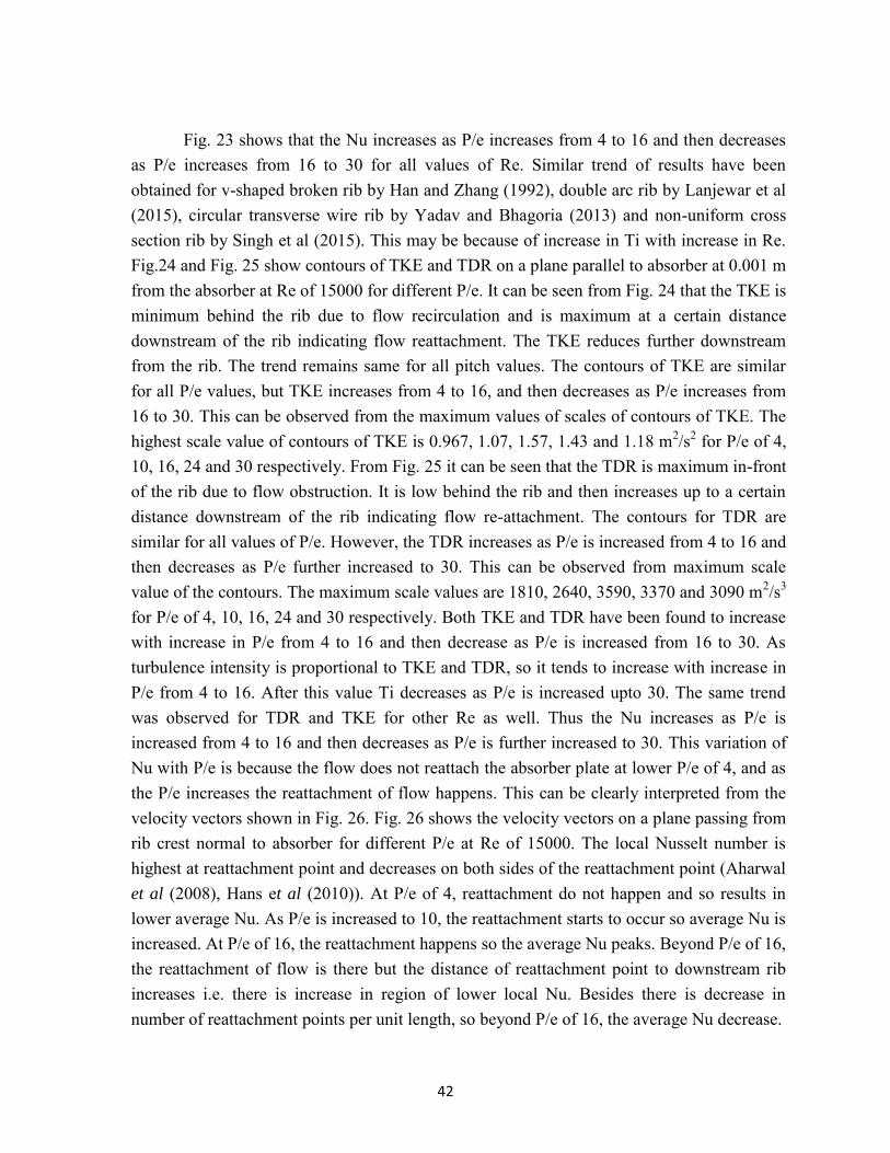
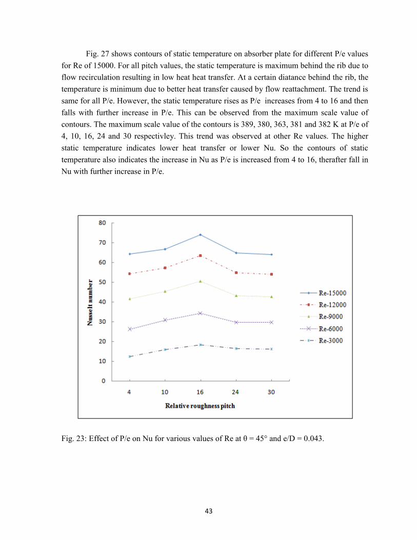
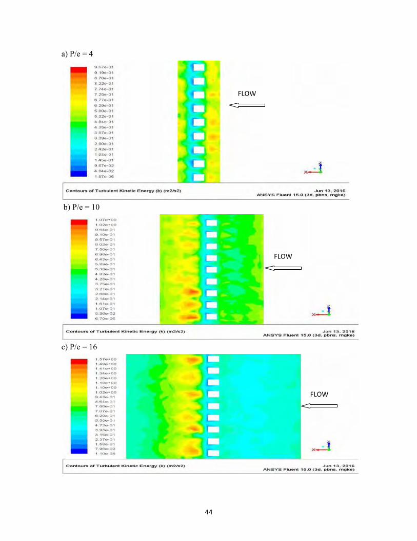
Fig. 23 shows that the Nu increases as P/e increases from 4 to 16 and then decreases
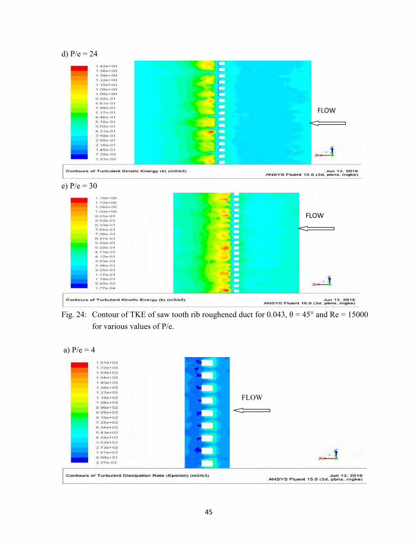
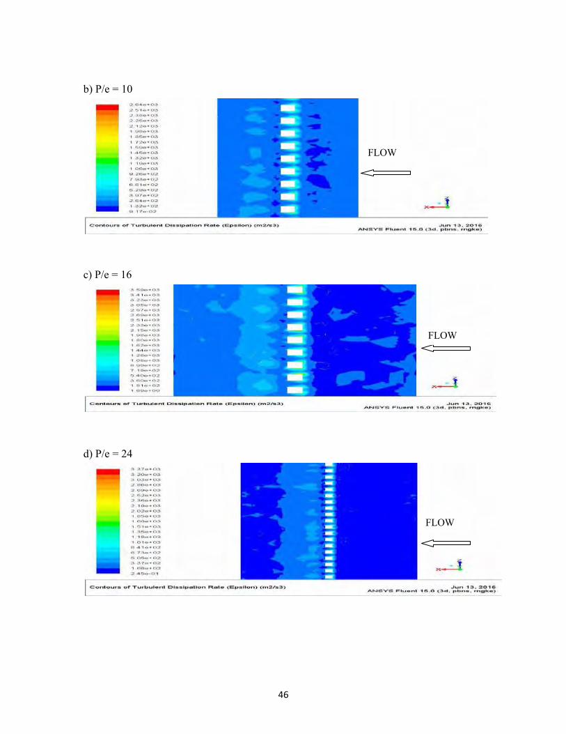
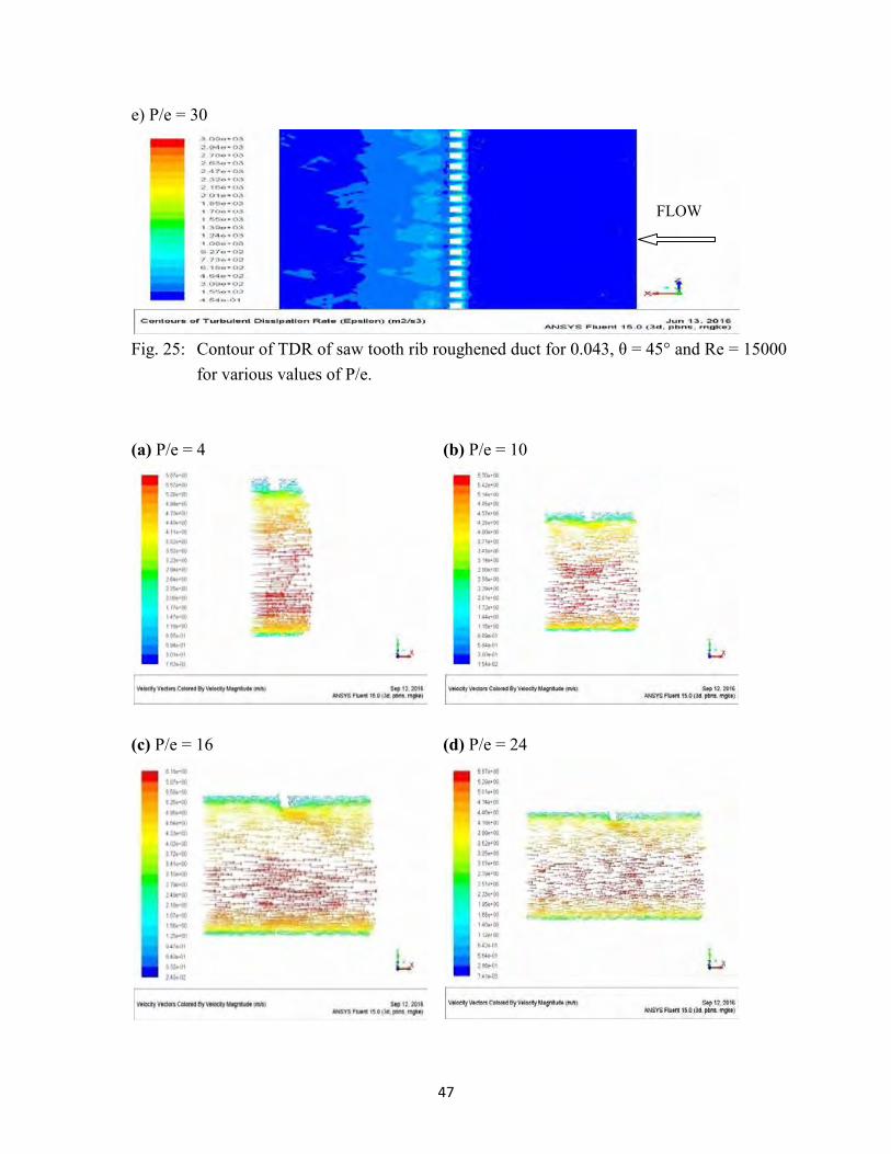
as P/e increases from 16 to 30 for all values of Re. Similar trend of results have been obtained for v-shaped broken rib by Han and Zhang (1992), double arc rib by Lanjewar et al (2015), circular transverse wire rib by Yadav and Bhagoria (2013) and non-uniform cross section rib by Singh et al (2015). This may be because of increase in Ti with increase in Re. Fig.24 and Fig. 25 show contours of TKE and TDR on a plane parallel to absorber at 0.001 m from the absorber at Re of 15000 for different P/e. It can be seen from Fig. 24 that the TKE is minimum behind the rib due to flow recirculation and is maximum at a certain distance downstream of the rib indicating flow reattachment. The TKE reduces further downstream from the rib. The trend remains same for all pitch values. The contours of TKE are similar for all P/e values, but TKE increases from 4 to 16, and then decreases as P/e increases from 16 to 30. This can be observed from the maximum values of scales of contours of TKE. The highest scale value of contours of TKE is 0.967, 1.07, 1.57, 1.43 and 1.18 m2/s2 for P/e of 4, 10, 16, 24 and 30 respectively. From Fig. 25 it can be seen that the TDR is maximum in-front of the rib due to flow obstruction. It is low behind the rib and then increases up to a certain distance downstream of the rib indicating flow re-attachment. The contours for TDR are similar for all values of P/e. However, the TDR increases as P/e is increased from 4 to 16 and then decreases as P/e further increased to 30. This can be observed from maximum scale value of the contours. The maximum scale values are 1810, 2640, 3590, 3370 and 3090 m2/s3 for P/e of 4, 10, 16, 24 and 30 respectively. Both TKE and TDR have been found to increase with increase in P/e from 4 to 16 and then decrease as P/e is increased from 16 to 30. As turbulence intensity is proportional to TKE and TDR, so it tends to increase with increase in P/e from 4 to 16. After this value Ti decreases as P/e is increased upto 30. The same trend was observed for TDR and TKE for other Re as well. Thus the Nu increases as P/e is increased from 4 to 16 and then decreases as P/e is further increased to 30. This variation of Nu with P/e is because the flow does not reattach the absorber plate at lower P/e of 4, and as the P/e increases the reattachment of flow happens. This can be clearly interpreted from the velocity vectors shown in Fig. 26. Fig. 26 shows the velocity vectors on a plane passing from rib crest normal to absorber for different P/e at Re of 15000. The local Nusselt number is highest at reattachment point and decreases on both sides of the reattachment point (Aharwal et al (2008), Hans et al (2010)). At P/e of 4, reattachment do not happen and so results in lower average Nu. As P/e is increased to 10, the reattachment starts to occur so average Nu is increased. At P/e of 16, the reattachment happens so the average Nu peaks. Beyond P/e of 16, the reattachment of flow is there but the distance of reattachment point to downstream rib increases i.e. there is increase in region of lower local Nu. Besides there is decrease in number of reattachment points per unit length, so beyond P/e of 16, the average Nu decrease.
43
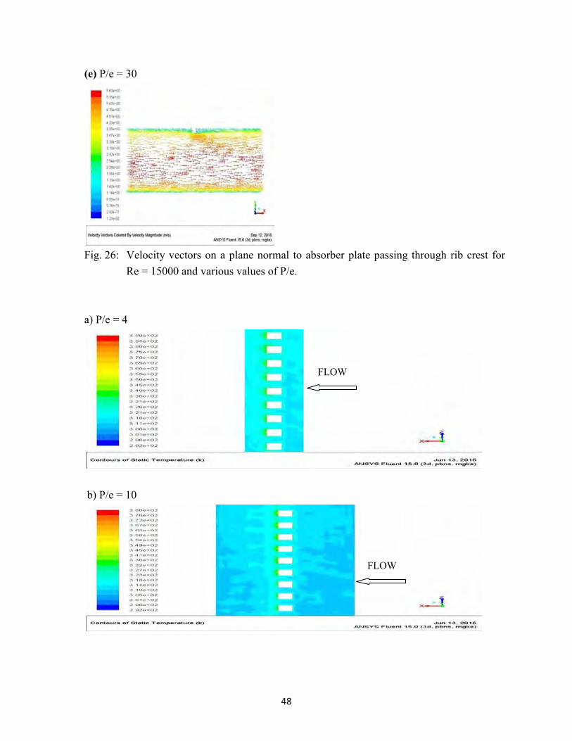
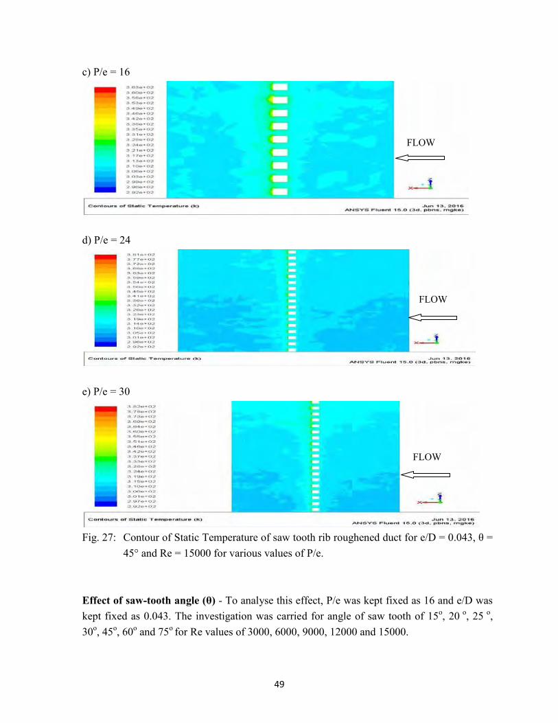
Fig. 27 shows contours of static temperature on absorber plate for different P/e values for Re of 15000. For all pitch values, the static temperature is maximum behind the rib due to flow recirculation resulting in low heat heat transfer. At a certain diatance behind the rib, the temperature is minimum due to better heat transfer caused by flow reattachment. The trend is same for all P/e. However, the static temperature rises as P/e increases from 4 to 16 and then falls with further increase in P/e. This can be observed from the maximum scale value of contours. The maximum scale value of the contours is 389, 380, 363, 381 and 382 K at P/e of 4, 10, 16, 24 and 30 respectivley. This trend was observed at other Re values. The higher static temperature indicates lower heat transfer or lower Nu. So the contours of static temperature also indicates the increase in Nu as P/e is increased from 4 to 16, therafter fall in Nu with further increase in P/e.
Fig. 23: Effect of P/e on Nu for various values of Re at θ = 45° and e/D = 0.043.
44
a) P/e = 4
b) P/e = 10
c) P/e = 16
FLOW
FLOW
FLOW
45
d) P/e = 24
e) P/e = 30
Fig. 24: Contour of TKE of saw tooth rib roughened duct for 0.043, θ = 45° and Re = 15000
for various values of P/e. a) P/e = 4
FLOW
FLOW
FLOW
46
b) P/e = 10
c) P/e = 16
d) P/e = 24
FLOW
FLOW
FLOW
47
e) P/e = 30
Fig. 25: Contour of TDR of saw tooth rib roughened duct for 0.043, θ = 45° and Re = 15000
for various values of P/e. (a) P/e = 4 (b) P/e = 10
(c) P/e = 16 (d) P/e = 24
FLOW
48
(e) P/e = 30
Fig. 26: Velocity vectors on a plane normal to absorber plate passing through rib crest for Re = 15000 and various values of P/e.
a) P/e = 4
b) P/e = 10
FLOW
FLOW
49
c) P/e = 16
d) P/e = 24
e) P/e = 30
Fig. 27: Contour of Static Temperature of saw tooth rib roughened duct for e/D = 0.043, θ =
45° and Re = 15000 for various values of P/e. Effect of saw-tooth angle (θ) - To analyse this effect, P/e was kept fixed as 16 and e/D was kept fixed as 0.043. The investigation was carried for angle of saw tooth of 15o, 20 o, 25 o, 30o, 45o, 60o and 75o for Re values of 3000, 6000, 9000, 12000 and 15000.
FLOW
FLOW
FLOW
50
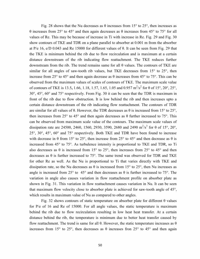
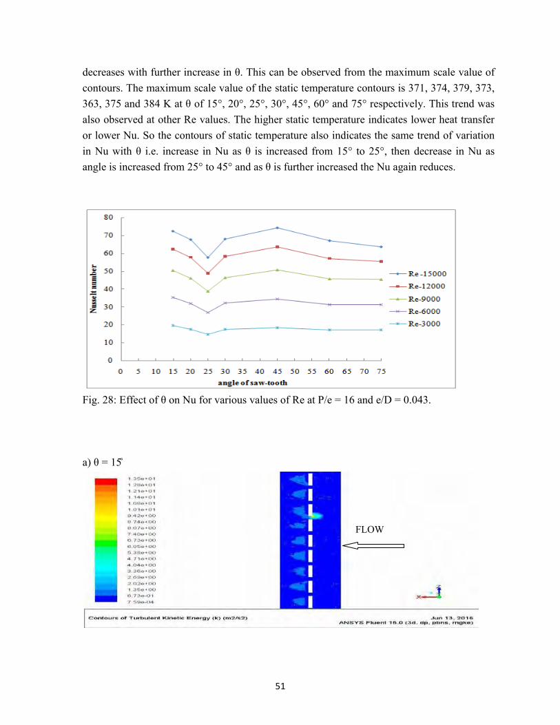
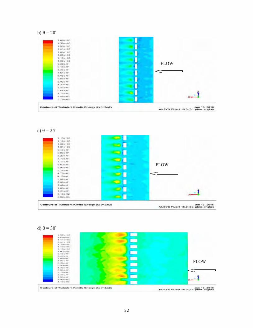
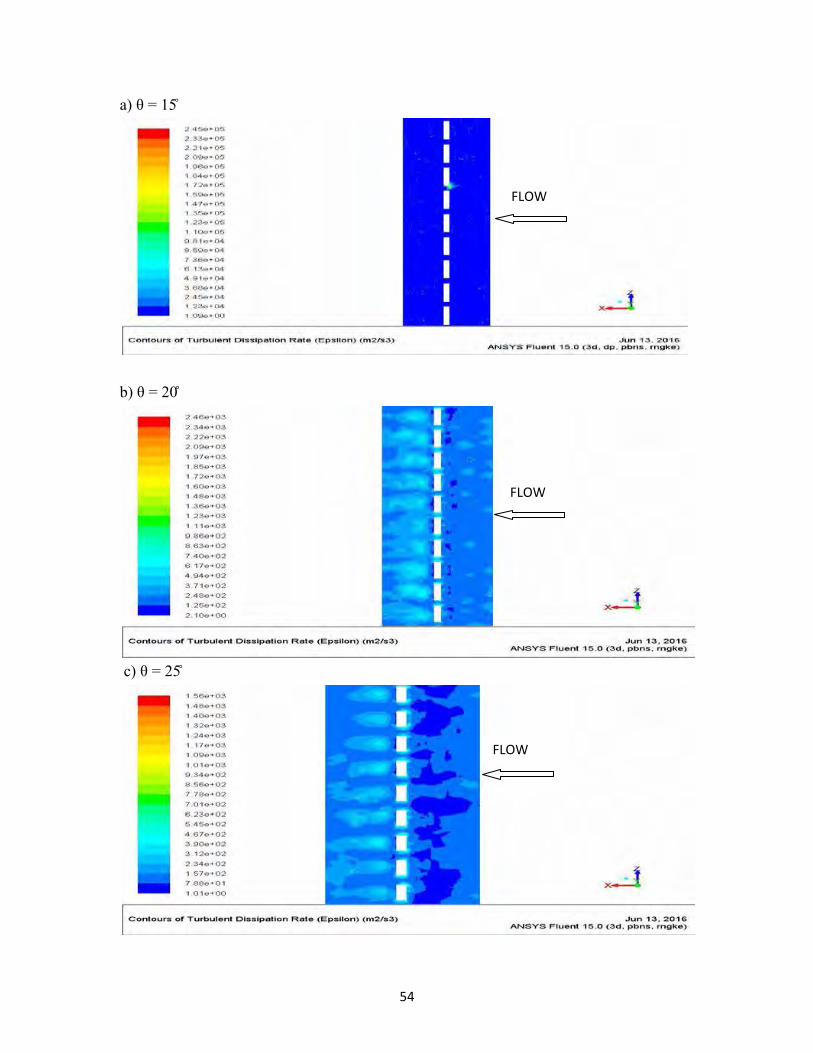
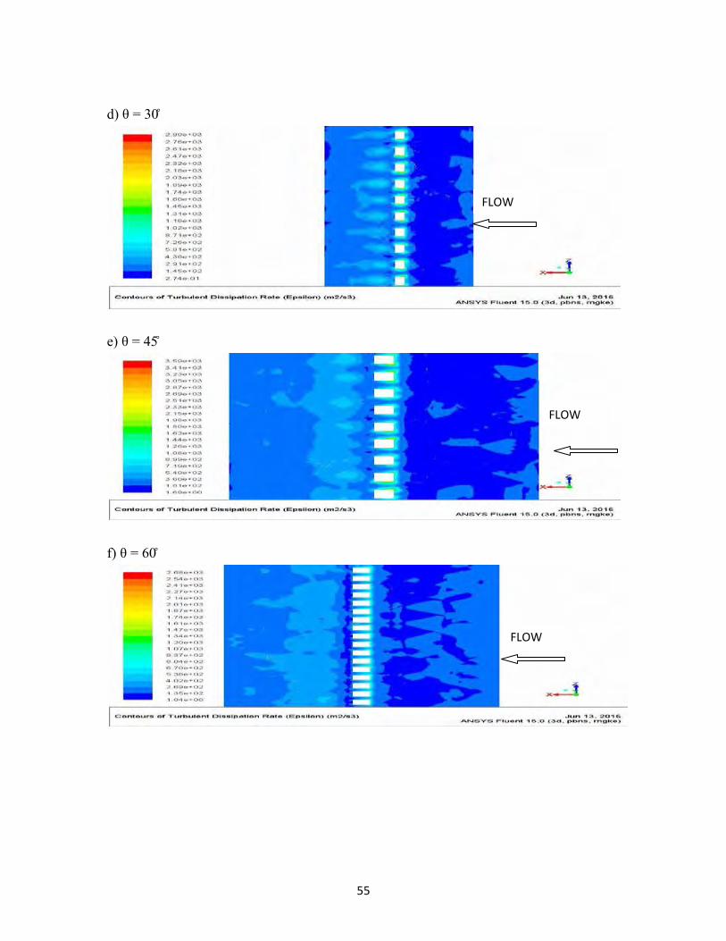
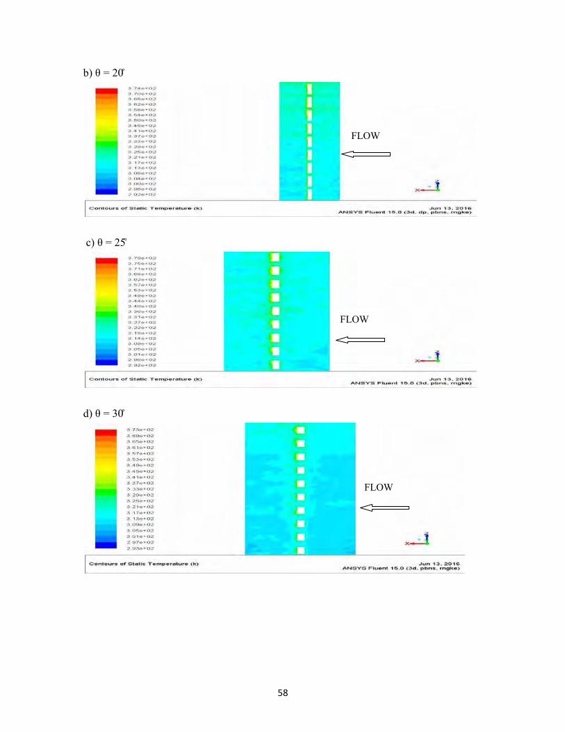
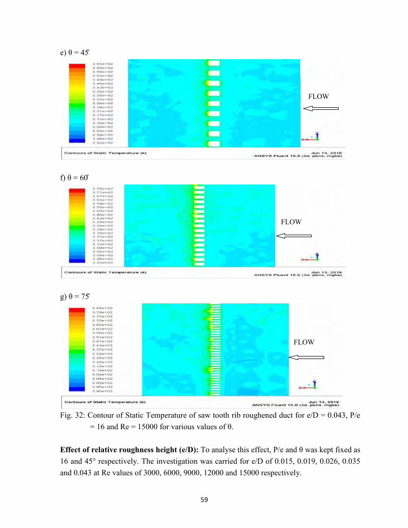
Fig. 28 shows that the Nu decreases as θ increases from 15° to 25°, then increases as θ increases from 25° to 45° and then again decreases as θ increases from 45° to 75° for all values of Re. This may be because of increase in Ti with increase in Re. Fig. 29 and Fig. 30 show contours of TKE and TDR on a plane parallel to absorber at 0.001 m from the absorber at P/e 16, e/D 0.043 and Re 15000 for different values of θ. It can be seen from Fig. 29 that the TKE is minimum behind the rib due to flow recirculation and is maximum at a certain distance downstream of the rib indicating flow reattachment. The TKE reduces further downstream from the rib. The trend remains same for all θ values. The contours of TKE are similar for all angles of saw-tooth rib values, but TKE decreases from 15° to 25°, then increase from 25° to 45° and then again decrease as θ increases from 45° to 75°. This can be observed from the maximum values of scales of contours of TKE. The maximum scale value of contours of TKE is 13.5, 1.66, 1.18, 1.57, 1.65, 1.05 and 0.957 m2/s2 for θ of 15°, 20°, 25°, 30°, 45°, 60° and 75° respectively. From Fig. 30 it can be seen that the TDR is maximum in front of the rib due to flow obstruction. It is low behind the rib and then increases upto a certain distance downstream of the rib indicating flow reattachment. The contours of TDR are similar for all values of θ. However, the TDR decreases as θ is increased from 15° to 25°, then increases from 25° to 45° and then again decreases as θ further increased to 75°. This can be observed from maximum scale value of the contours. The maximum scale values of dissipation rate are 24500, 2460, 1560, 2930, 3590, 2680 and 2490 m2/s3 for θ of 15°, 20°, 25°, 30°, 45°, 60° and 75° respectively. Both TKE and TDR have been found to increase with decrease in θ from 15° to 25°, then increase from 25° to 45° and then decrease as θ is increased from 45° to 75°. As turbulence intensity is proportional to TKE and TDR, so Ti also decreases as θ is increased from 15° to 25°, then increases from 25° to 45° and then decreases as θ is further increased to 75°. The same trend was observed for TDR and TKE for other Re as well. As the Nu is proportional to Ti that varies directly with TKE and dissipation rate, so the Nu decreases as θ is increased from 15° to 25°, then Nu increases as angle is increased from 25° to 45° and then decreases as θ is further increased to 75°. The variation in angle also causes variation in flow reattachment profile on absorber plate as shown in Fig. 31. This variation in flow reattachment causes variation in Nu. It can be seen that maximum flow velocity close to absorber plate is achieved for saw-tooth angle of 45°, which results in maximum value of Nu as compared to other angles.
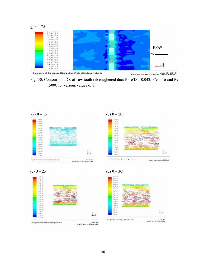
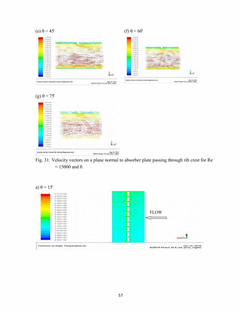
Fig. 32 shows contours of static temperature on absorber plate for different θ values for P/e of 16 and Re of 15000. For all angle values, the static temperature is maximum behind the rib due to flow recirculation resulting in low heat heat transfer. At a certain distance behind the rib, the temperature is minimum due to better heat transfer caused by flow reattachment. The trend is same for all θ. However, the static temperature increases as θ increases from 15° to 25°, then decreases as θ increases fron 25° to 45° and then again
51
decreases with further increase in θ. This can be observed from the maximum scale value of contours. The maximum scale value of the static temperature contours is 371, 374, 379, 373, 363, 375 and 384 K at θ of 15°, 20°, 25°, 30°, 45°, 60° and 75° respectively. This trend was also observed at other Re values. The higher static temperature indicates lower heat transfer or lower Nu. So the contours of static temperature also indicates the same trend of variation in Nu with θ i.e. increase in Nu as θ is increased from 15° to 25°, then decrease in Nu as angle is increased from 25° to 45° and as θ is further increased the Nu again reduces.
Fig. 28: Effect of θ on Nu for various values of Re at P/e = 16 and e/D = 0.043.
a) θ = 15̊
FLOW
52
b) θ = 20̊
c) θ = 25̊
d) θ = 30̊
FLOW
FLOW
FLOW
53
e) θ = 45̊
f) θ = 60̊
g) θ = 75̊
Fig. 29: Contour of TKE of saw tooth rib roughened duct for e/D = 0.043, P/e = 16 and Re =
15000 for various values of θ.
FLOW
FLOW
FLOW
54
a) θ = 15 ̊
b) θ = 20̊
c) θ = 25̊
FLOW
FLOW
FLOW
55
d) θ = 30̊
e) θ = 45̊
f) θ = 60̊
FLOW
FLOW
FLOW
56
g) θ = 75̊
Fig. 30: Contour of TDR of saw tooth rib roughened duct for e/D = 0.043, P/e = 16 and Re =
15000 for various values of θ. (a) θ = 15̊
(b) θ = 20̊
(c) θ = 25̊ (d) θ = 30̊
FLOW
57
(e) θ = 45̊ (f) θ = 60̊
(g) θ = 75 ̊
Fig. 31: Velocity vectors on a plane normal to absorber plate passing through rib crest for Re = 15000 and θ.
a) θ = 15 ̊
FLOW
58
b) θ = 20̊
c) θ = 25̊
d) θ = 30̊
FLOW
FLOW
FLOW
59
e) θ = 45̊
f) θ = 60̊
g) θ = 75̊
Fig. 32: Contour of Static Temperature of saw tooth rib roughened duct for e/D = 0.043, P/e
= 16 and Re = 15000 for various values of θ. Effect of relative roughness height (e/D): To analyse this effect, P/e and θ was kept fixed as 16 and 45° respectively. The investigation was carried for e/D of 0.015, 0.019, 0.026, 0.035 and 0.043 at Re values of 3000, 6000, 9000, 12000 and 15000 respectively.
FLOW
FLOW
FLOW
60
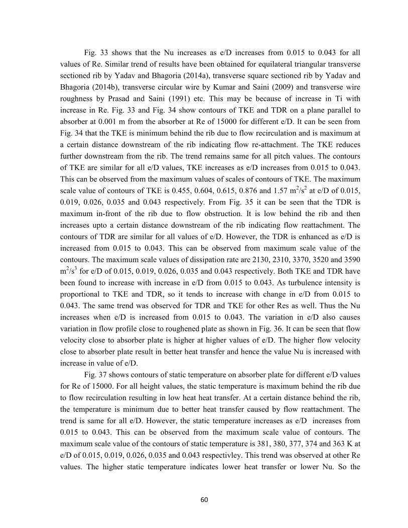
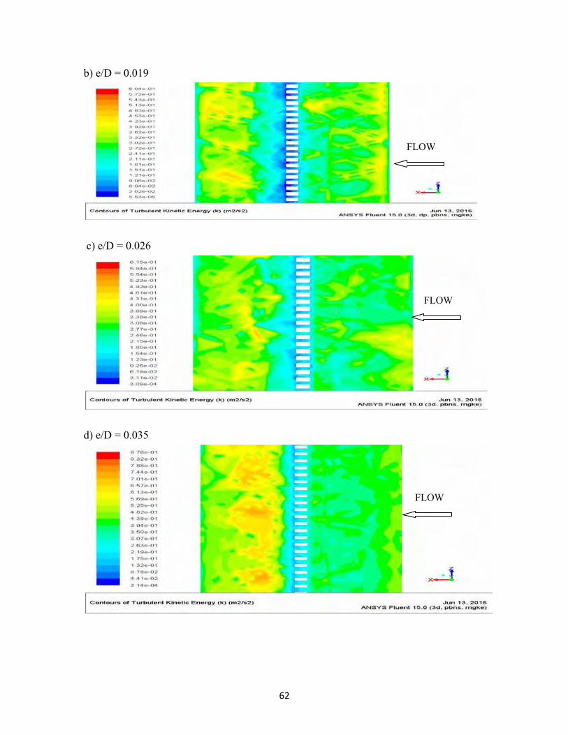
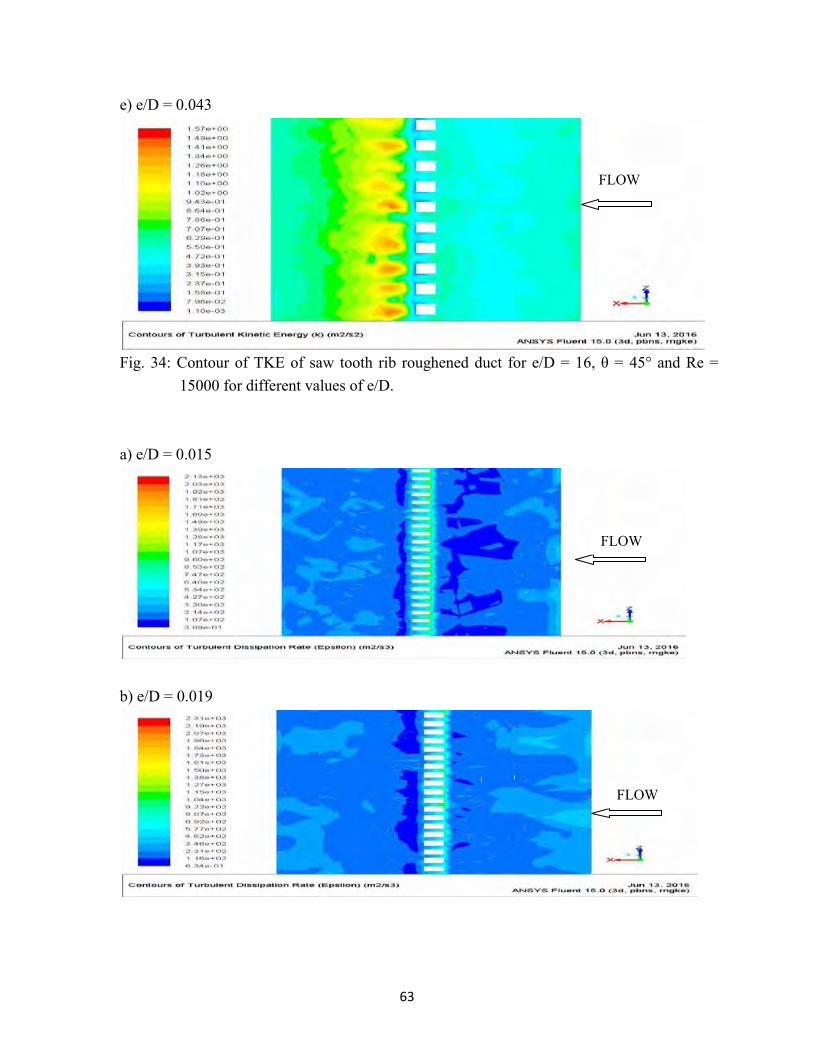
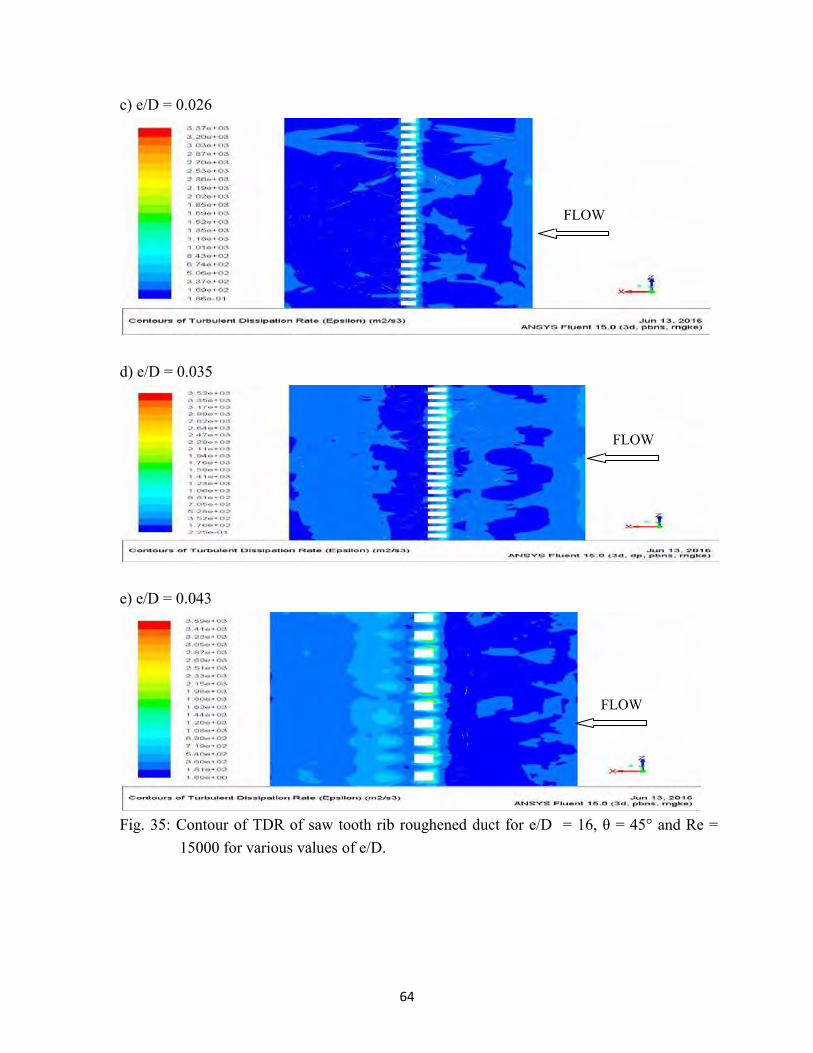
Fig. 33 shows that the Nu increases as e/D increases from 0.015 to 0.043 for all values of Re. Similar trend of results have been obtained for equilateral triangular transverse sectioned rib by Yadav and Bhagoria (2014a), transverse square sectioned rib by Yadav and Bhagoria (2014b), transverse circular wire by Kumar and Saini (2009) and transverse wire roughness by Prasad and Saini (1991) etc. This may be because of increase in Ti with increase in Re. Fig. 33 and Fig. 34 show contours of TKE and TDR on a plane parallel to absorber at 0.001 m from the absorber at Re of 15000 for different e/D. It can be seen from Fig. 34 that the TKE is minimum behind the rib due to flow recirculation and is maximum at a certain distance downstream of the rib indicating flow re-attachment. The TKE reduces further downstream from the rib. The trend remains same for all pitch values. The contours of TKE are similar for all e/D values, TKE increases as e/D increases from 0.015 to 0.043. This can be observed from the maximum values of scales of contours of TKE. The maximum scale value of contours of TKE is 0.455, 0.604, 0.615, 0.876 and 1.57 m2/s2 at e/D of 0.015, 0.019, 0.026, 0.035 and 0.043 respectively. From Fig. 35 it can be seen that the TDR is maximum in-front of the rib due to flow obstruction. It is low behind the rib and then increases upto a certain distance downstream of the rib indicating flow reattachment. The contours of TDR are similar for all values of e/D. However, the TDR is enhanced as e/D is increased from 0.015 to 0.043. This can be observed from maximum scale value of the contours. The maximum scale values of dissipation rate are 2130, 2310, 3370, 3520 and 3590 m2/s3 for e/D of 0.015, 0.019, 0.026, 0.035 and 0.043 respectively. Both TKE and TDR have been found to increase with increase in e/D from 0.015 to 0.043. As turbulence intensity is proportional to TKE and TDR, so it tends to increase with change in e/D from 0.015 to 0.043. The same trend was observed for TDR and TKE for other Res as well. Thus the Nu increases when e/D is increased from 0.015 to 0.043. The variation in e/D also causes variation in flow profile close to roughened plate as shown in Fig. 36. It can be seen that flow velocity close to absorber plate is higher at higher values of e/D. The higher flow velocity close to absorber plate result in better heat transfer and hence the value Nu is increased with increase in value of e/D.
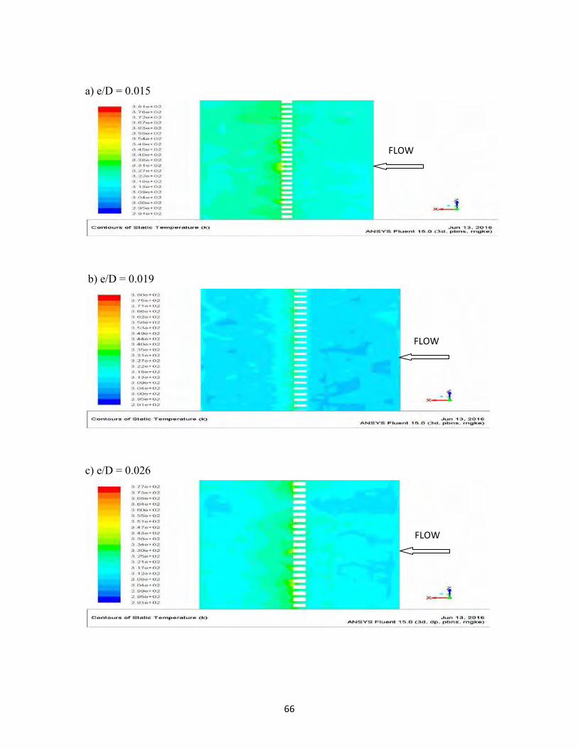
Fig. 37 shows contours of static temperature on absorber plate for different e/D values for Re of 15000. For all height values, the static temperature is maximum behind the rib due to flow recirculation resulting in low heat heat transfer. At a certain distance behind the rib, the temperature is minimum due to better heat transfer caused by flow reattachment. The trend is same for all e/D. However, the static temperature increases as e/D increases from 0.015 to 0.043. This can be observed from the maximum scale value of contours. The maximum scale value of the contours of static temperature is 381, 380, 377, 374 and 363 K at e/D of 0.015, 0.019, 0.026, 0.035 and 0.043 respectivley. This trend was observed at other Re values. The higher static temperature indicates lower heat transfer or lower Nu. So the
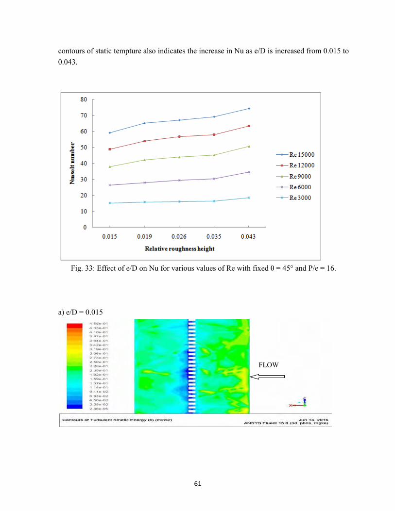
61
contours of static tempture also indicates the increase in Nu as e/D is increased from 0.015 to 0.043.
Fig. 33: Effect of e/D on Nu for various values of Re with fixed θ = 45° and P/e = 16.
a) e/D = 0.015
FLOW
62
b) e/D = 0.019
c) e/D = 0.026
d) e/D = 0.035
FLOW
FLOW
FLOW
63
e) e/D = 0.043
Fig. 34: Contour of TKE of saw tooth rib roughened duct for e/D = 16, θ = 45° and Re =
15000 for different values of e/D. a) e/D = 0.015
b) e/D = 0.019
FLOW
FLOW
FLOW
64
c) e/D = 0.026
d) e/D = 0.035
e) e/D = 0.043
Fig. 35: Contour of TDR of saw tooth rib roughened duct for e/D = 16, θ = 45° and Re =
15000 for various values of e/D.
FLOW
FLOW
FLOW
65
(a) e/D = 0.015 (b) e/D = 0.019
(c) e/D = 0.026 (d) e/D = 0.035
(e) e/D = 0.043
Fig. 36: Velocity vectors on a plane normal to absorber plate passing through rib crest for Re = 15000 and e/D.
66
a) e/D = 0.015
b) e/D = 0.019
c) e/D = 0.026
FLOW
FLOW
FLOW

67
d) e/D = 0.035
e) e/D = 0.043
Fig. 37: Contour of Static Temperature of saw tooth rib roughened duct for 16, θ = 45° and
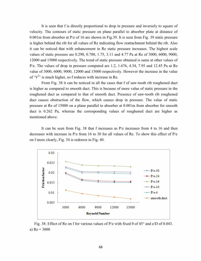
Re = 15000 for various values of e/D. 6.2 Friction factor (f) characteristics Effect of relative roughness pitch (P/e): To investigate this effect, e/D and θ of rib roughness were kept fixed as 0.043 and 45° respectively. This investigation was carried out for P/e values 4, 10, 16, 24 and 30 and Re values of 3000, 6000, 9000, 12000 and 15000 respectively.
Fig. 38 indicates the effect of Re on f for various values of P/e with fixed saw-tooth angle and e/D. The value of f decreases with increase in the value of Re which is due to decrease in thickness of laminar sub-layer with the rise in Re. We can write
𝑓 ∝∆𝑃
𝑉2
FLOW
68
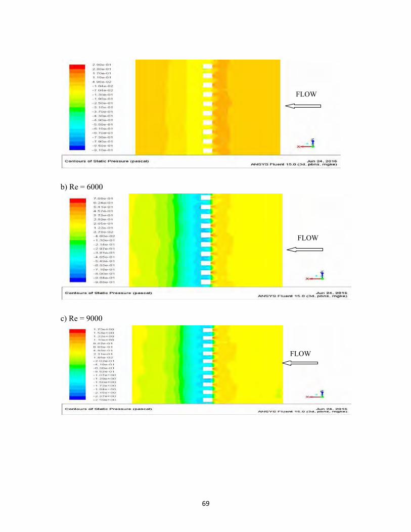
It is seen that f is directly proportional to drop in pressure and inversely to square of velocity. The contours of static pressure on plane parallel to absorber plate at distance of 0.001m from absorber at P/e of 16 are shown in Fig.39. It is seen from Fig. 39 static pressure is higher behind the rib for all values of Re indicating flow reattachment behind the rib. Also it can be noticed that with enhancement in Re static pressure increases. The highest scale values of static pressure are 0.290, 0.780, 1.75, 3.11 and 4.77 Pa at Re of 3000, 6000, 9000, 12000 and 15000 respectively. The trend of static pressure obtained is same at other values of P/e. The values of drop in pressure computed are 1.2, 1.676, 4.34, 7.95 and 12.45 Pa at Re value of 3000, 6000, 9000, 12000 and 15000 respectively. However the increase in the value of ‘V2’ is much higher, so f reduces with increase in Re.
From Fig. 38 it can be noticed in all the cases that f of saw-tooth rib roughened duct is higher as compared to smooth duct. This is because of more value of static pressure in the roughened duct as compared to that of smooth duct. Presence of saw-tooth rib roughened duct causes obstruction of the flow, which causes drop in pressure. The value of static pressure at Re of 15000 on a plane parallel to absorber at 0.001m from absorber for smooth duct is 0.262 Pa, whereas the corresponding values of roughened duct are higher as mentioned above.
It can be seen from Fig. 38 that f increases as P/e increases from 4 to 16 and then
decreases with increase in P/e from 16 to 30 for all values of Re. To show this effect of P/e on f more clearly, Fig. 34 is redrawn in Fig. 40.
Fig. 38: Effect of Re on f for various values of P/e with fixed θ of 45° and e/D of 0.043.
a) Re = 3000
69
b) Re = 6000
c) Re = 9000
FLOW
FLOW
FLOW
70
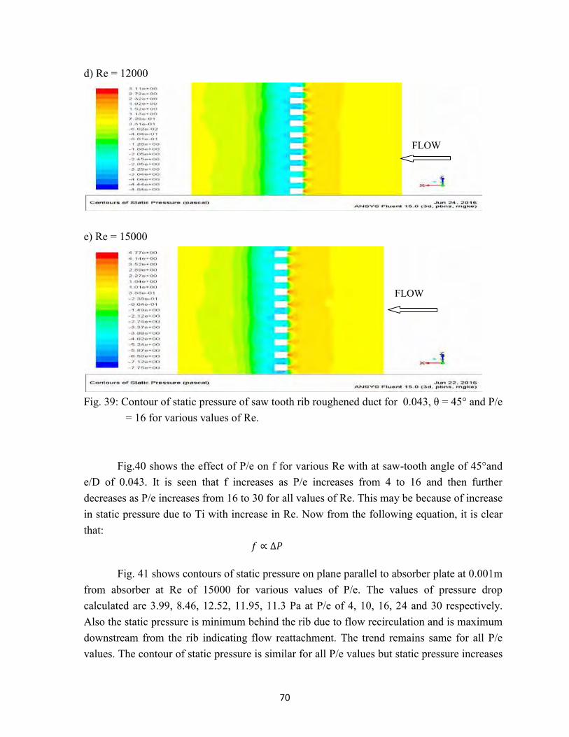
d) Re = 12000
e) Re = 15000
Fig. 39: Contour of static pressure of saw tooth rib roughened duct for 0.043, θ = 45° and P/e
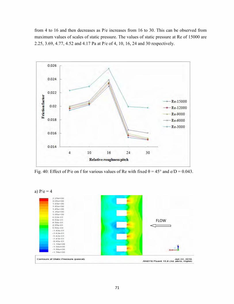
= 16 for various values of Re. Fig.40 shows the effect of P/e on f for various Re with at saw-tooth angle of 45°and
e/D of 0.043. It is seen that f increases as P/e increases from 4 to 16 and then further decreases as P/e increases from 16 to 30 for all values of Re. This may be because of increase in static pressure due to Ti with increase in Re. Now from the following equation, it is clear that: 𝑓 ∝ ∆𝑃
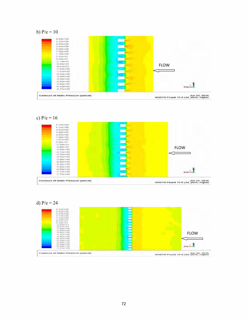
Fig. 41 shows contours of static pressure on plane parallel to absorber plate at 0.001m from absorber at Re of 15000 for various values of P/e. The values of pressure drop calculated are 3.99, 8.46, 12.52, 11.95, 11.3 Pa at P/e of 4, 10, 16, 24 and 30 respectively. Also the static pressure is minimum behind the rib due to flow recirculation and is maximum downstream from the rib indicating flow reattachment. The trend remains same for all P/e values. The contour of static pressure is similar for all P/e values but static pressure increases
FLOW
FLOW
71
from 4 to 16 and then decreases as P/e increases from 16 to 30. This can be observed from maximum values of scales of static pressure. The values of static pressure at Re of 15000 are 2.25, 3.69, 4.77, 4.52 and 4.17 Pa at P/e of 4, 10, 16, 24 and 30 respectively.
Fig. 40: Effect of P/e on f for various values of Re with fixed θ = 45° and e/D = 0.043. a) P/e = 4
FLOW
72
b) P/e = 10
c) P/e = 16
d) P/e = 24
FLOW
FLOW
FLOW
73
e) P/e = 30
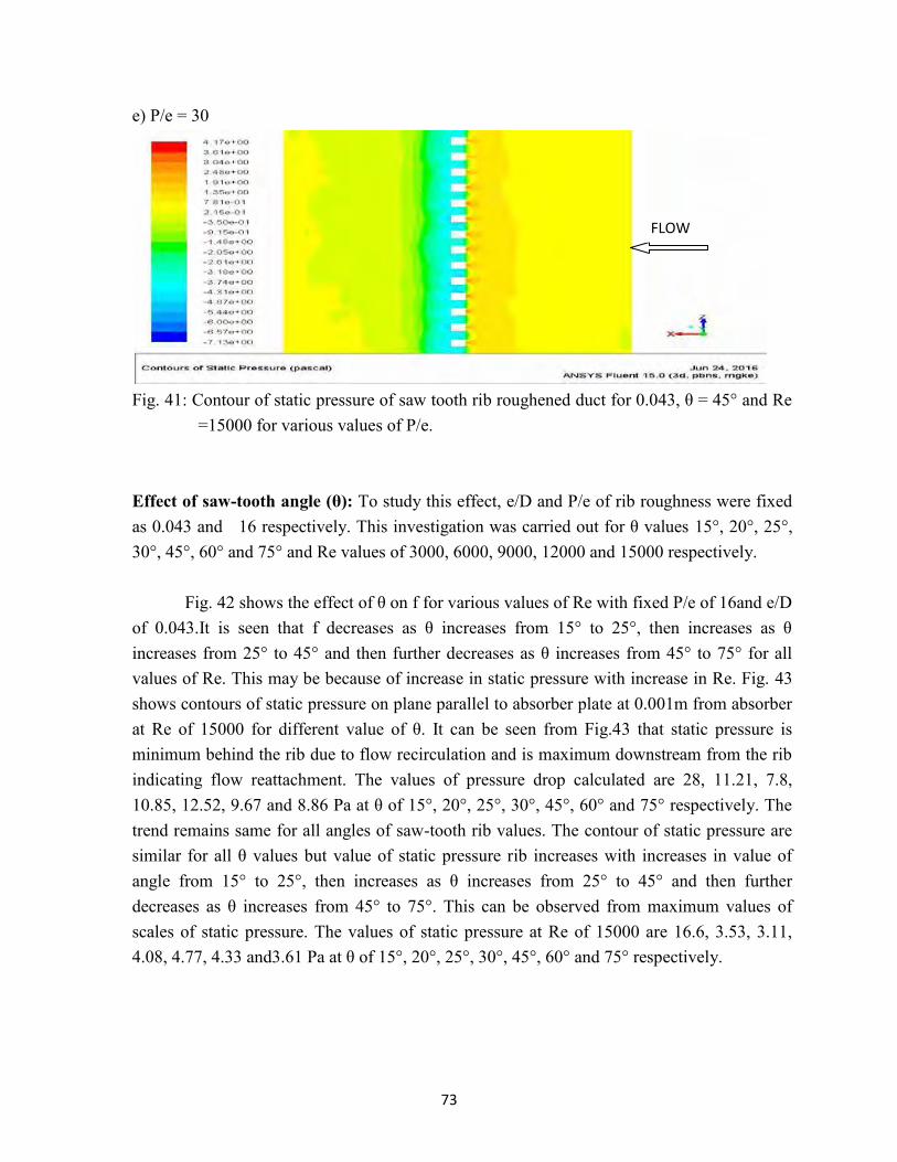
Fig. 41: Contour of static pressure of saw tooth rib roughened duct for 0.043, θ = 45° and Re
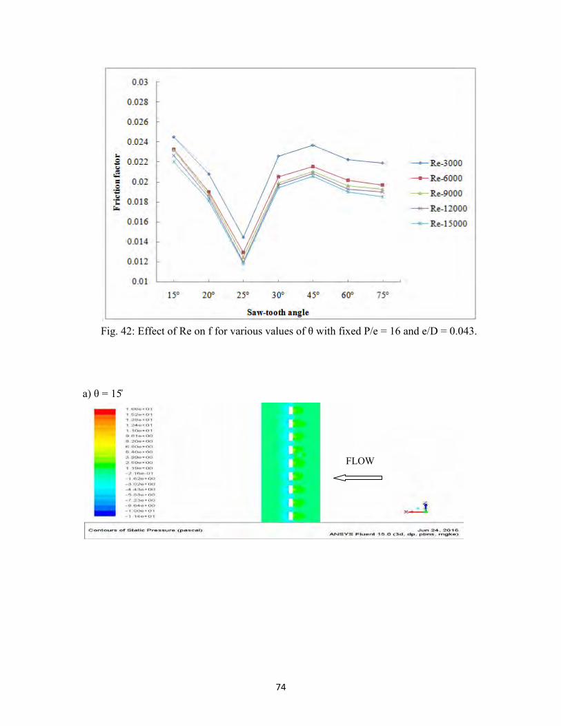
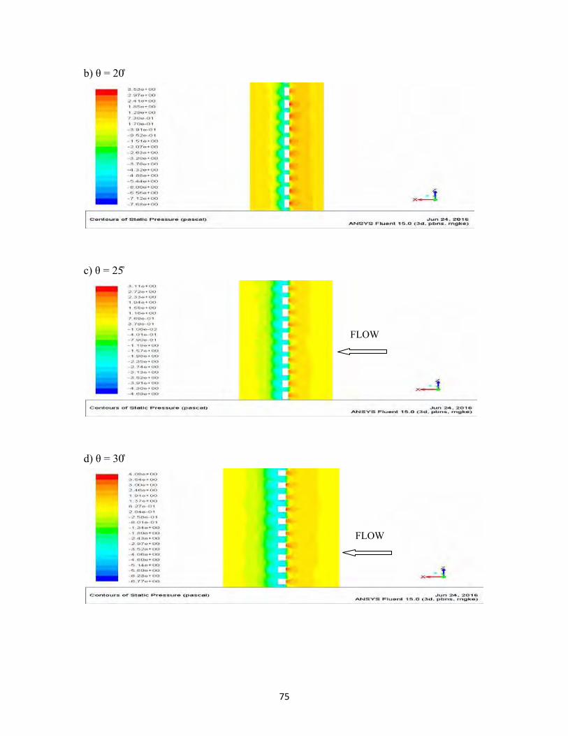
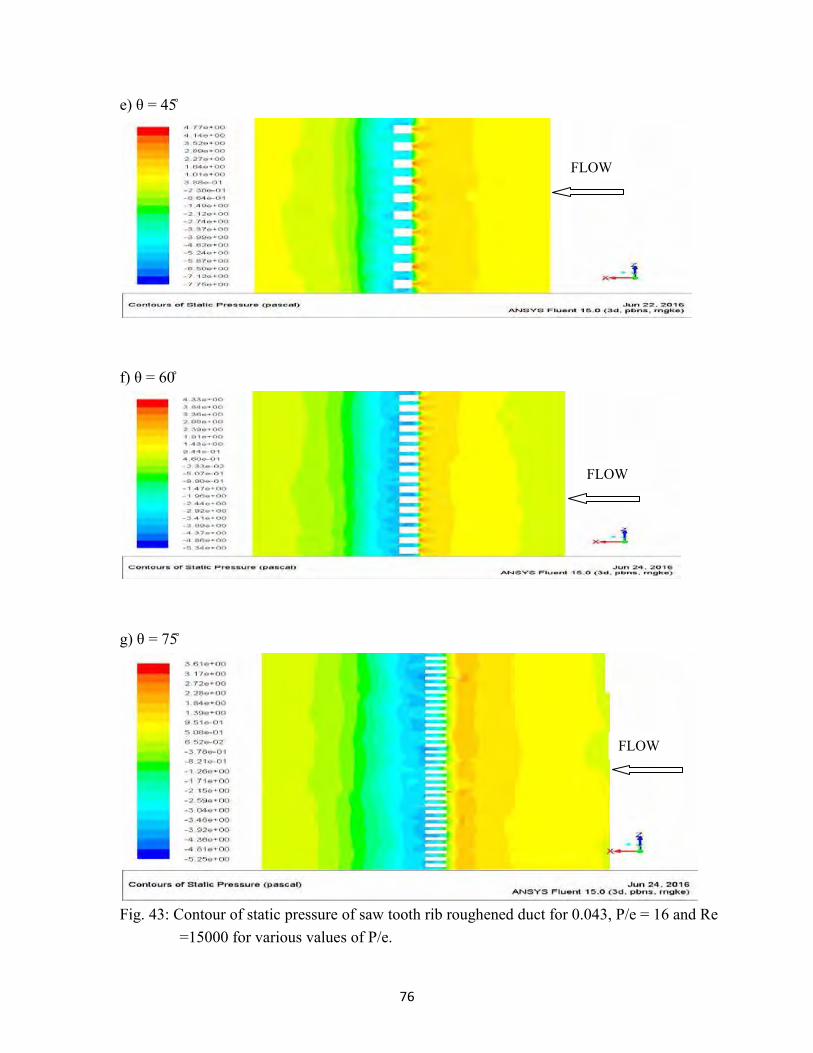
=15000 for various values of P/e. Effect of saw-tooth angle (θ): To study this effect, e/D and P/e of rib roughness were fixed as 0.043 and 16 respectively. This investigation was carried out for θ values 15°, 20°, 25°, 30°, 45°, 60° and 75° and Re values of 3000, 6000, 9000, 12000 and 15000 respectively.
Fig. 42 shows the effect of θ on f for various values of Re with fixed P/e of 16and e/D of 0.043.It is seen that f decreases as θ increases from 15° to 25°, then increases as θ increases from 25° to 45° and then further decreases as θ increases from 45° to 75° for all values of Re. This may be because of increase in static pressure with increase in Re. Fig. 43 shows contours of static pressure on plane parallel to absorber plate at 0.001m from absorber at Re of 15000 for different value of θ. It can be seen from Fig.43 that static pressure is minimum behind the rib due to flow recirculation and is maximum downstream from the rib indicating flow reattachment. The values of pressure drop calculated are 28, 11.21, 7.8, 10.85, 12.52, 9.67 and 8.86 Pa at θ of 15°, 20°, 25°, 30°, 45°, 60° and 75° respectively. The trend remains same for all angles of saw-tooth rib values. The contour of static pressure are similar for all θ values but value of static pressure rib increases with increases in value of angle from 15° to 25°, then increases as θ increases from 25° to 45° and then further decreases as θ increases from 45° to 75°. This can be observed from maximum values of scales of static pressure. The values of static pressure at Re of 15000 are 16.6, 3.53, 3.11, 4.08, 4.77, 4.33 and3.61 Pa at θ of 15°, 20°, 25°, 30°, 45°, 60° and 75° respectively.
FLOW
74
Fig. 42: Effect of Re on f for various values of θ with fixed P/e = 16 and e/D = 0.043.
a) θ = 15̊
FLOW
75
b) θ = 20̊
c) θ = 25̊
d) θ = 30̊
FLOW
FLOW
76
e) θ = 45̊
f) θ = 60̊
g) θ = 75̊
Fig. 43: Contour of static pressure of saw tooth rib roughened duct for 0.043, P/e = 16 and Re
=15000 for various values of P/e.
FLOW
FLOW
FLOW
77
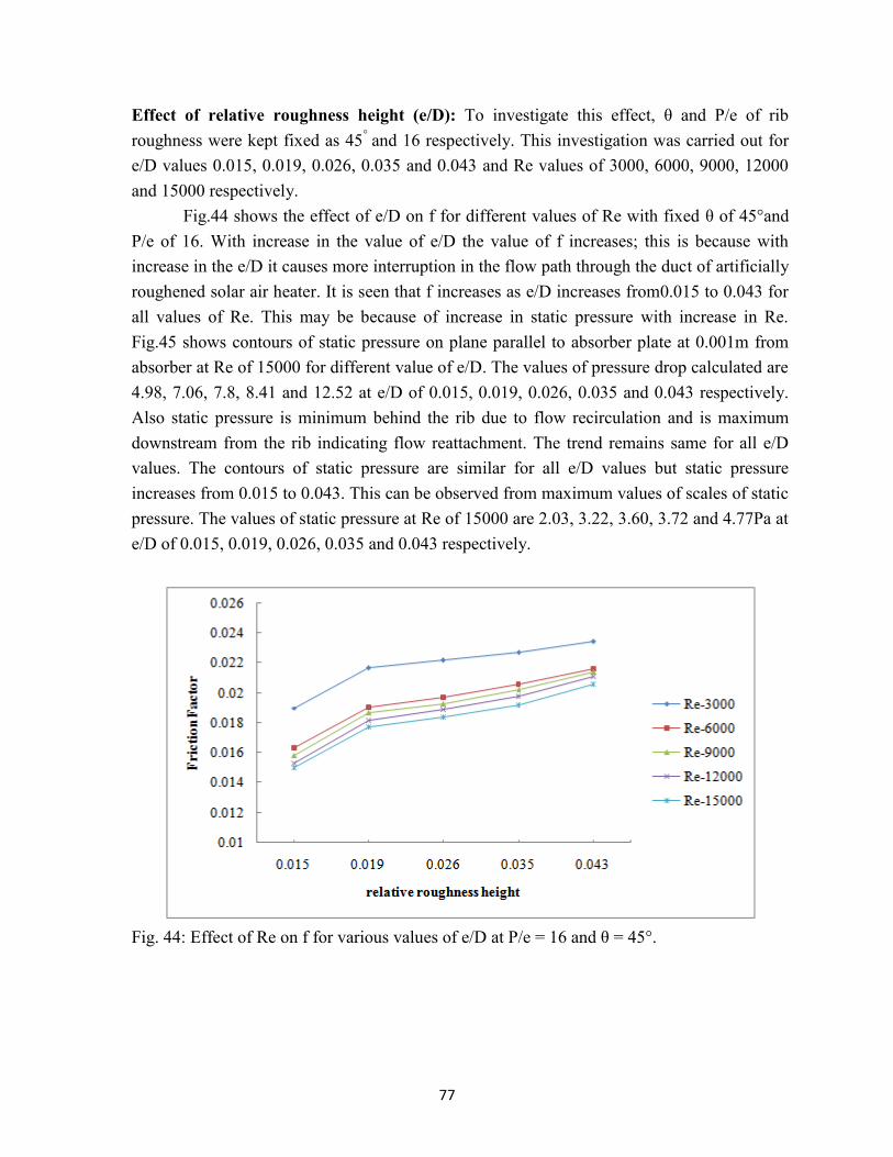
Effect of relative roughness height (e/D): To investigate this effect, θ and P/e of rib roughness were kept fixed as 45° and 16 respectively. This investigation was carried out for e/D values 0.015, 0.019, 0.026, 0.035 and 0.043 and Re values of 3000, 6000, 9000, 12000 and 15000 respectively.
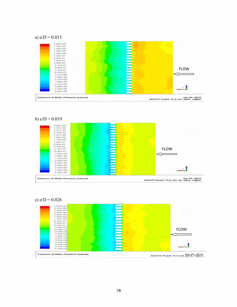
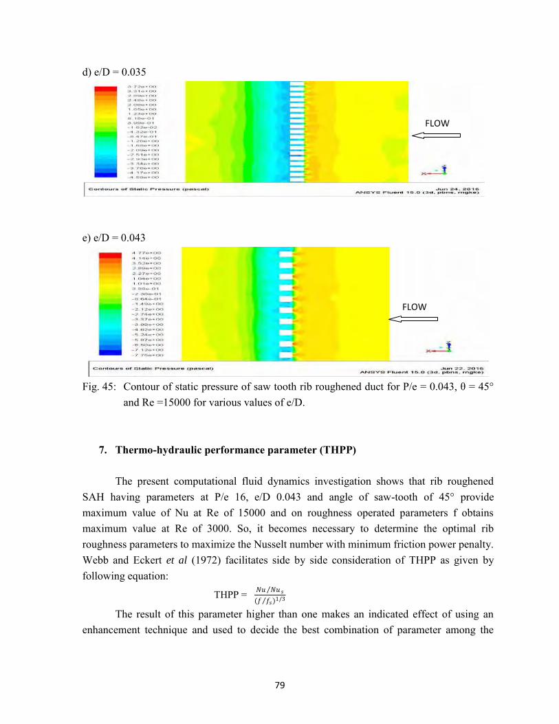
Fig.44 shows the effect of e/D on f for different values of Re with fixed θ of 45°and P/e of 16. With increase in the value of e/D the value of f increases; this is because with increase in the e/D it causes more interruption in the flow path through the duct of artificially roughened solar air heater. It is seen that f increases as e/D increases from0.015 to 0.043 for all values of Re. This may be because of increase in static pressure with increase in Re. Fig.45 shows contours of static pressure on plane parallel to absorber plate at 0.001m from absorber at Re of 15000 for different value of e/D. The values of pressure drop calculated are 4.98, 7.06, 7.8, 8.41 and 12.52 at e/D of 0.015, 0.019, 0.026, 0.035 and 0.043 respectively. Also static pressure is minimum behind the rib due to flow recirculation and is maximum downstream from the rib indicating flow reattachment. The trend remains same for all e/D values. The contours of static pressure are similar for all e/D values but static pressure increases from 0.015 to 0.043. This can be observed from maximum values of scales of static pressure. The values of static pressure at Re of 15000 are 2.03, 3.22, 3.60, 3.72 and 4.77Pa at e/D of 0.015, 0.019, 0.026, 0.035 and 0.043 respectively.
Fig. 44: Effect of Re on f for various values of e/D at P/e = 16 and θ = 45°.
78
a) e/D = 0.015
b) e/D = 0.019
c) e/D = 0.026
FLOW
FLOW
FLOW
79
d) e/D = 0.035
e) e/D = 0.043
Fig. 45: Contour of static pressure of saw tooth rib roughened duct for P/e = 0.043, θ = 45°
and Re =15000 for various values of e/D.
7. Thermo-hydraulic performance parameter (THPP)
The present computational fluid dynamics investigation shows that rib roughened SAH having parameters at P/e 16, e/D 0.043 and angle of saw-tooth of 45° provide maximum value of Nu at Re of 15000 and on roughness operated parameters f obtains maximum value at Re of 3000. So, it becomes necessary to determine the optimal rib roughness parameters to maximize the Nusselt number with minimum friction power penalty. Webb and Eckert et al (1972) facilitates side by side consideration of THPP as given by following equation:
THPP = 𝑁𝑢 𝑁𝑢𝑠
(𝑓 𝑓𝑠)1/3
The result of this parameter higher than one makes an indicated effect of using an enhancement technique and used to decide the best combination of parameter among the
FLOW
FLOW

80
performance of number of arrangements. The effect of Re, P/e, θ and e/D on THPP are described below:
Fig.46 indicates the effect of Re on THPP for various values of P/e at e/D of 0.043 and θ of 45°. It is found that value of THPP varies between 1.15 to 1.45 for all cases of P/e. It is observed that THPP enhances with increase in Re upto 9000 and decreases with further increment in Re from 9000 to 15000. Further, it may be noted that P/e of 16, Re of 9000, e/D of 0.043 and θ of 45° obtains the better THPP for studied range of Re. To show the effect of P/e on THPP more clearly Fig. 46 is redrawn in Fig.47.
Fig. 46: Effect of Re on THHP for various values of P/e at θ = 45° and e/D = 0.043.
Fig.47 shows that the THPP increases as the value of P/e increases from 4 to 16 and
then decreases as P/e increases from 16 to 30 for all values of Re. Hence, there exists an optimum value of P/e of 16 which gives the best THPP.
81
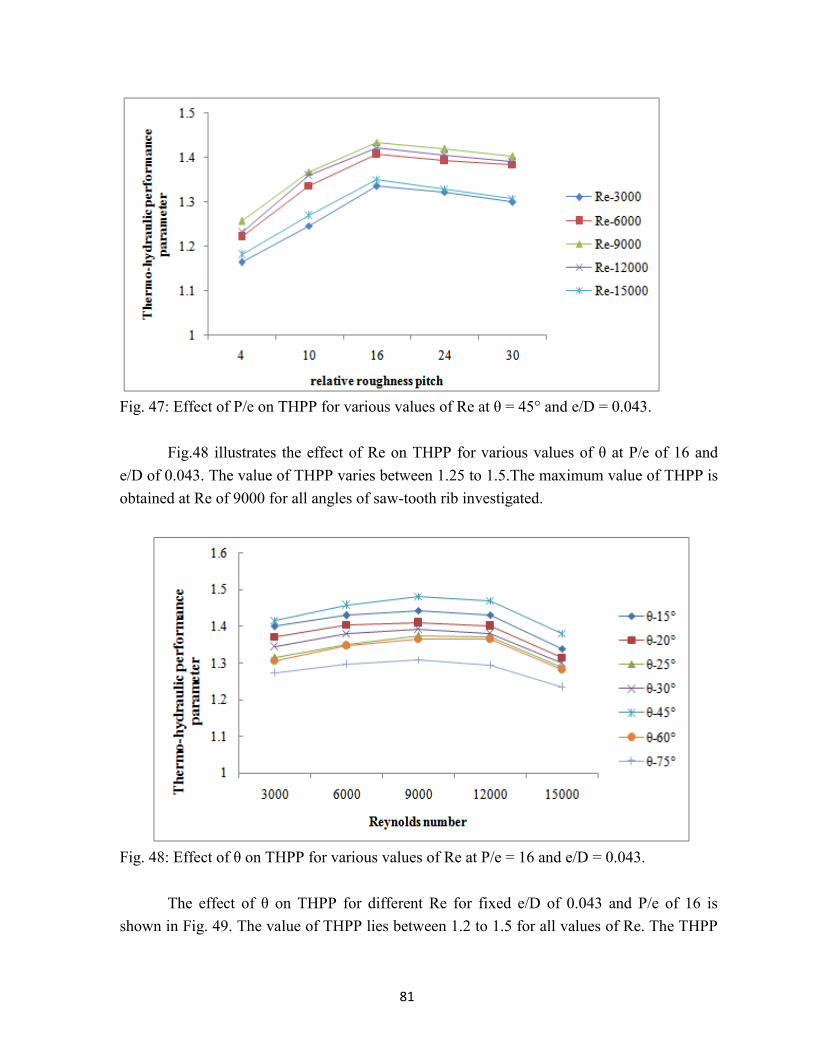
Fig. 47: Effect of P/e on THPP for various values of Re at θ = 45° and e/D = 0.043.
Fig.48 illustrates the effect of Re on THPP for various values of θ at P/e of 16 and e/D of 0.043. The value of THPP varies between 1.25 to 1.5.The maximum value of THPP is obtained at Re of 9000 for all angles of saw-tooth rib investigated.
Fig. 48: Effect of θ on THPP for various values of Re at P/e = 16 and e/D = 0.043.
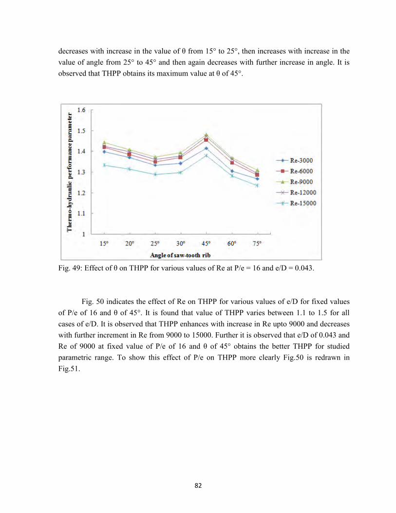
The effect of θ on THPP for different Re for fixed e/D of 0.043 and P/e of 16 is shown in Fig. 49. The value of THPP lies between 1.2 to 1.5 for all values of Re. The THPP
82
decreases with increase in the value of θ from 15° to 25°, then increases with increase in the value of angle from 25° to 45° and then again decreases with further increase in angle. It is observed that THPP obtains its maximum value at θ of 45°.
Fig. 49: Effect of θ on THPP for various values of Re at P/e = 16 and e/D = 0.043.
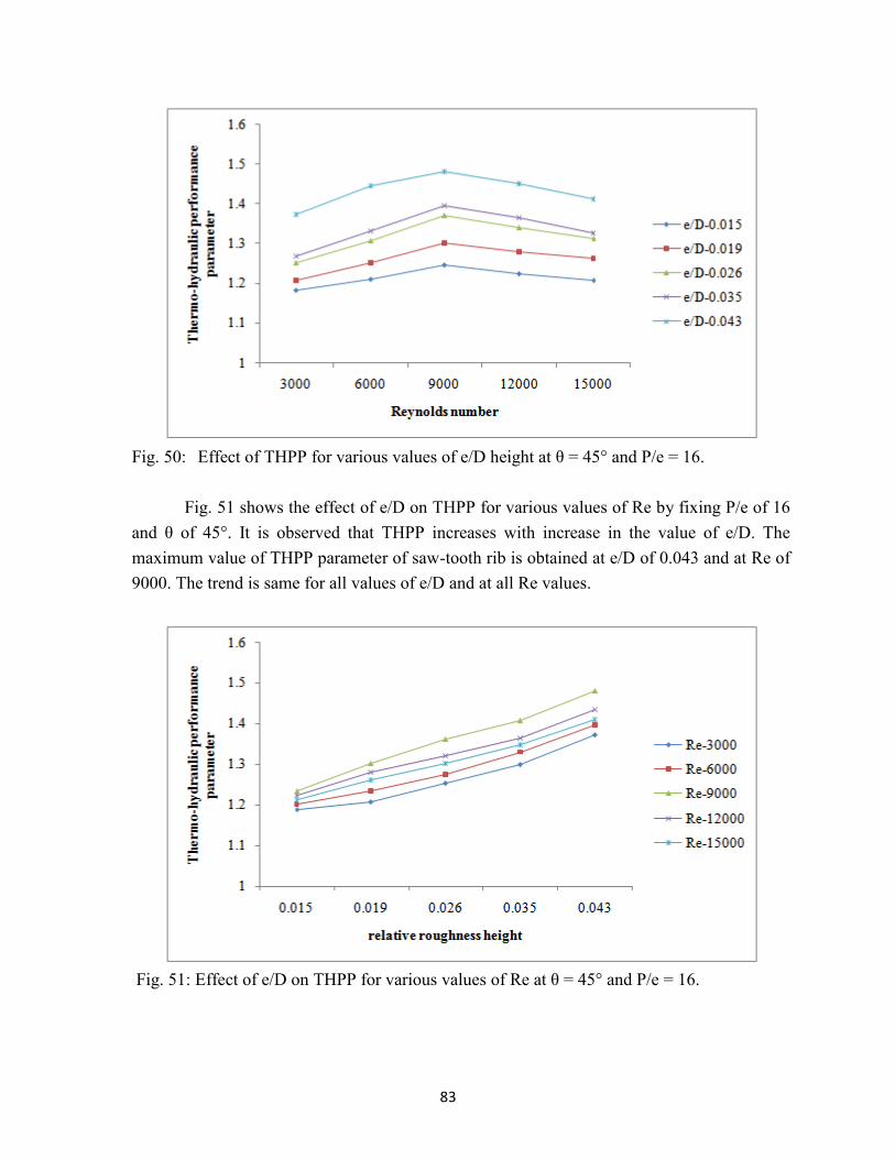
Fig. 50 indicates the effect of Re on THPP for various values of e/D for fixed values
of P/e of 16 and θ of 45°. It is found that value of THPP varies between 1.1 to 1.5 for all cases of e/D. It is observed that THPP enhances with increase in Re upto 9000 and decreases with further increment in Re from 9000 to 15000. Further it is observed that e/D of 0.043 and Re of 9000 at fixed value of P/e of 16 and θ of 45° obtains the better THPP for studied parametric range. To show this effect of P/e on THPP more clearly Fig.50 is redrawn in Fig.51.
83
Fig. 50: Effect of THPP for various values of e/D height at θ = 45° and P/e = 16.
Fig. 51 shows the effect of e/D on THPP for various values of Re by fixing P/e of 16
and θ of 45°. It is observed that THPP increases with increase in the value of e/D. The maximum value of THPP parameter of saw-tooth rib is obtained at e/D of 0.043 and at Re of 9000. The trend is same for all values of e/D and at all Re values.
Fig. 51: Effect of e/D on THPP for various values of Re at θ = 45° and P/e = 16.
84
Thus it can be summed up that combination of parameters having P/e of 16, θ of 45°, e/D of 0.043 and Re of 9000 results in best THPP of 1.5.
8. Correlations for Nusselt number and friction factor
From, CFD results, the correlations for Nusselt number and friction factor have been developed as a function of flow and roughness parameters as given in equations below:
0.485 2 0.1320.847 0.0020.017 Re exp 0.098lnP P e
Nue e D
0.738 2 0.1240.101 0.0300.033Re exp 0.178lnP P e
fe e D
The respective R2 values obtained are 0.972 and 0.392 thereby indicating that the fitted that the model is highly significant (p<0.001).
9. Summary and Conclusions The air flow in conventional solar air heater (SAH) is turbulent, which causes
development of viscous sub-layer near absorber. It results in lower thermal performance. The use of artificial rib roughness for breaking viscous sub-layer to enhance thermal performance of conventional SAH is most widely used technique. Numerous investigations on rib roughness have been reported in literature. Most of the reported investigations are experimental. A few investigations using CFD software ANSYS CFD / FLUENT have also been reported. These studies have investigated uniform cross-section rib roughness geometries. In this study, published results have been validated using CFD and a new geometry has been selected. The new selected geometry has non-uniform cross-section. It has been found to produce higher thermal performance than ribs of uniform cross-section. In this study, a parametric study on non-uniform saw-tooth cross-section rib roughness has been undertaken to investigate heat and fluid flow of solar air heater duct roughened with saw-tooth transverse rib roughness. The correlations for Nusselt number and friction factor have also been obtained. The investigation has been done in 3-D using CFD software ANSYS Academic Research 15.0. The relative roughness height (e/D), saw-tooth angle (θ) and relative roughness pitch (P/e) were varied from 15° to 75°, 0.015 to 0.043 and 4 to 30 respectively. The Reynolds number ranged from 3000 to 15000. Turbulence model RNG k-ε and roughened duct of periodic section were selected for analysis. From the present study, the following are conclusions drawn:
85
(i) As Reynolds number increases, friction factor decreases and Nusselt number increases. The variation of static temperature contours on absorber also confirms this trend.
(ii) As relative roughness pitch increases from 4 to 16, the friction factor and Nusselt number increases and then both decreases as relative roughness pitch is increased from 16 to 30. This is because of change in flow attachment in-between the ribs. The variation is further substantiated by the turbulent kinetic energy, static temperature and static pressure contours showing same trend.
(iii) Both, the friction factor and Nusselt number are maximum for saw-tooth angle of 45° for all investigated Reynolds number.
(iv) As relative roughness height increases, friction factor and Nusselt number increases for all investigated Reynolds number due to higher turbulence generated due to obstruction in flow path.
(v) The relative roughness pitch of 0.043, saw-tooth angle of 45°, relative roughness pitch of 16 and Reynolds number of 9000 resulted in maximum ‘thermo-hydraulic performance parameter’ of 1.48.
(vi) The correlations of Nusselt number (Nu) and friction factor (f) obtained from CFD
investigation in terms of Reynolds number, relative roughness pitch, relative
roughness height and angle of saw tooth are given below: 0.485 2 0.132
0.847 0.0020.017 Re exp 0.098lnP P eNu
e e D
0.738 2 0.1240.101 0.0300.033Re exp 0.178lnP P e
fe e D
The respective R2 values obtained are 0.972 and 0.392 thereby indicating that the fitted model is highly significant (p<0.001).

86
PUBLICATIONS: 1. Singh S, Singh B, Hans VS, Gill RS. CFD (computational fluid dynamics) investigation
on Nusselt number and friction factor of solar air heater duct roughened with non-
uniform cross-section transverse rib. Energy 84 (2015) 509-517.
2. Singh A, Singh S. CFD investigation on roughness pitch variation in non-uniform cross-
section transverse rib roughness on Nusselt number and friction factor characteristics of
solar air heater duct. Energy 128 (2017) 109-127.
iii. Has the progress been according to original plan of work and towards achieving the objectives. if not, state reasons Yes
iv. Please indicate the difficulties, if any, experienced in implementing the
project Nil
v. If project has not been completed, please indicate the approximate time by
which it is likely to be completed. A summary of the work done for the period (Annual basis) may please be sent to the Commission on a separate sheet. N/A
vi. If the project has been completed, please enclose a summary of the findings of the study. One bound copy of the final report of work done may also be sent to University Grants Commission.
Summarizing the CFD investigation on rib roughness in solar air heater duct, a new type of rib roughness having non-uniform cross-section has been studied. It has been found to produce higher thermal performance than ribs of uniform cross-section. In this study, a parametric investigation on non-uniform saw-tooth cross-section rib roughness has been undertaken to investigate heat and fluid flow of solar air heater duct roughened with saw-tooth transverse rib roughness. The correlations for Nusselt number and friction factor have

87
also been obtained. The investigation has been done in 3-D using CFD software ANSYS Academic Research 15.0. The relative roughness height (e/D), saw-tooth angle (θ) and relative roughness pitch (P/e) were varied from 15° to 75°, 0.015 to 0.043 and 4 to 30 respectively. The Reynolds number ranged from 3000 to 15000. Turbulence model RNG k-ε and roughened duct of periodic section were selected for analysis. From the present study, it has been found that as Reynolds number increases, friction factor decreases and Nusselt number increases. The variation of static temperature contours on absorber also confirms this trend. As relative roughness pitch increases from 4 to 16, the friction factor and Nusselt number increases and then both decreases as relative roughness pitch is increased from 16 to 30. This is because of change in flow attachment in-between the ribs. The variation is further substantiated by the turbulent kinetic energy, static temperature and static pressure contours showing same trend. Both, the friction factor and Nusselt number are maximum for saw-tooth angle of 45° for all investigated Reynolds number. As relative roughness height increases, friction factor and Nusselt number increases for all investigated Reynolds number due to higher turbulence generated due to obstruction in flow path. The relative roughness pitch of 0.043, saw-tooth angle of 45°, relative roughness pitch of 16 and Reynolds number of 9000 resulted in maximum ‘thermo-hydraulic performance parameter’ of 1.48. The correlations of Nusselt number (Nu) and friction factor (f) have been obtained from CFD investigation in terms of Reynolds number, relative roughness pitch, relative roughness height and angle of saw tooth. The respective R2 values obtained are 0.972 and 0.392 thereby indicating that the fitted model is highly significant (p<0.001).
vii. Any other information which would help in evaluation of work done on the project. At the completion of the project, the first report should indicate the output, such as (a) Manpower trained (b) Ph. D. awarded (c) Publication of results (d) other impact, if any
Two research papers have been published in Energy: the international journal (Elsevier) in the year 2015 and 2017 of impact factor 4.844 and 4.292 respectively.


