Embed Size (px)
Citation preview
© 2017 IJEDR | Volume 5, Issue 1 | ISSN: 2321-9939
IJEDR1701082 International Journal of Engineering Development and Research (www.ijedr.org) 534
Analysis of Flow Through Solar Dryer Duct Using
CFD 1Prof. A.I. Ambesange, 2 Prof. Kusekar S.K.
1Workshop superintendent Sandip Institute of polytechnic, Nashik, Maharastra, India, 2 Assistant Prof. Dept. of Mechanical
Engineering, ZCOER, Pune, Maharastra, India
________________________________________________________________________________________________________
Abstract - Energy is a crucial input in the process of economic, social and industrial development of any nation. During
past several decades, energy demand of the world has been increasing continuously at an alarming rate due to increase in
population, industrialization, transportation etc. Continuous use of fossil fuels have resulted energy crisis and
environment degradation at global level. On the many alternatives, solar energy is an important renewable energy
resource that has the potential of fulfilling all energy needs. Some important applications of solar energy are solar water
heating, solar space heating/cooling, solar cooking, solar crop drying, solar power generation etc. Simplest method to
utilize solar radiation is to convert it into thermal energy for heating applications by using solar collectors. Solar air Dryer
because of their inherent simplicity are cheap and are used for many domestic and commercial applications like space
heating, crop drying, wood seasoning etc. In this paper the objective of the CFD flow study is to design, test and optimize
flow-conditioning devices, as appropriate, to guide the gas flow through the duct. In this a two-dimensional numerical
simulation of the heat transfer, Nussult number, Velocity and temperature was conducted using the CFD code FLUENT
VERSION 14.5. The CFD modeling involves numerical solutions of the conservation equations for mass, momentum and
energy. These three equations are used to model the convective heat transfer process with the following assumptions;
(a)The flow is steady, fully developed, turbulent and two dimensional. (b) Incompressible fluid and flow.(c) The duct wall,
absorber plate and roughness material are homogeneous and isotropic.
_______________________________________________________________________________________________________
1. INTRODUCTION
1.1 General Energy Scenario
The use of solar energy in recent years had reached a remarkable edge. The continuous research for an alternative power source
due to the perceived scarcity of fuel fossils is its driving force. It had become even more popular as the cost of fossil fuel
continues to rise. Of all the renewable sources of energy available, solar energy is the most abundant one and is available in both
direct as well as indirect forms. Solar energy applications were divided mainly into two categories: the first is the direct
conversion to electricity using solar cells (electrical applications). The second is the thermal applications. The latter include solar
heating, solar cooling, solar drying, solar cooking, solar ponds, solar distillation, solar furnaces, solar thermal power generation,
solar water heating, solar air heating, etc. Detailed description, fundamentals and previous work performed on solar dryers and
solar air heaters, as the vital element for the indirect and mixed modes of solar dryers.
Solar air heater is a type of energy collector in which the energy from the sun, solar insolation, is captured by an absorbing
medium and used to heat air. Solar air heating is a renewable energy heating technology used to dry the agricultural products
effectively and efficiently. A simple solar air collector consists of an absorber material, sometimes having a selective surface, to
capture radiation from the sun and transfers this thermal energy to air via conduction heat transfer. This heated air is then ducted
to the agricultural products such as chilies, grapes etc.
Drying or dehydration of material means removal of moisture from the interior of the material to the surface and then to remove
the moisture from the surface of drying material. Drying of seeds prevents germinations and growth and fungi and bacteria. The
traditional age old practices of drying food crops in developing countries like India,0 Bangladesh etc. is spreading food products
in open sun termed as open sun drying or natural sun drying.This natural sun drying is simple and economical but suffers from
many drawbacks such as there is no control over the drying rate discoloration .
However, being unprotected from rain, windborne dirt and dust, infestation by insects, rodents and other animal, products may be
seriously degraded to the extent that sometimes become inedible and the resulted loss of food quality in the dried Products may
have adverse economic effects on domestics and international markets. Some of the problems associated with open-air sun drying
can be solved through the use of a solar dryer which comprises of collector, a drying chamber and sometimes a chimney. The use
of solar technology has often been suggested for the dried fruit industry both to reduce energy costs and economically speed up
drying which would be beneficial to final quality dried grapes, okra, tomato and onion using solar energy. They concluded that
drying time reduced significantly resulting in a higher product quality in terms of colour and reconstitution properties. They also
believe that ascompared to oil or gas heated dryers, solar drying facilities are economical for small holders, especially under
favourable meteorological conditions. Solar dryers used in agriculture for food and crop drying,for industrial drying process,
dryers can be proved to be most useful device from energy conservation point of view.
1.2 Computational Fluid Dynamics (CFD)
Computational fluid dynamics, usually abbreviated as CFD, is a branch offluid mechanics that uses numerical
analysis and algorithms to solve and analyze problems that involve fluid flows. Computers are used to perform the calculations
required to simulate the interaction of liquids and gases with surfaces defined by boundary conditions. With high-
© 2017 IJEDR | Volume 5, Issue 1 | ISSN: 2321-9939
IJEDR1701082 International Journal of Engineering Development and Research (www.ijedr.org) 535
speed supercomputers, better solutions can be achieved. Ongoing research yields software that improves the accuracy and speed
of complex simulation scenarios such astransonic or turbulent flows. Initial experimental validation of such software is performed
using a wind tunnel with the final validation coming in full-scale testing, e.g. flight tests.
1.2.1 What is CFD?
Computational Fluid Dynamics (CFD) provides a qualitative (and sometimes even quantitative) prediction of fluid flows by
means of
mathematical modeling (partial differential equations)
numerical methods (discretization and solution techniques)
software tools (solvers, pre- and post processing utilities)
Fig 1: CFD Simulation
1.2.2 Why use CFD?
Numerical simulations of fluid flow (will) enable
• Architects to design comfortable and safe living environments
• Chemical engineers to maximize the yield from their equipment
• Petroleum engineers to devise optimal oil recovery strategies
• Surgeons to cure arterial diseases (computational hemodynamics)
• Meteorologists to forecast the weather and warn of natural disasters
• Safety experts to reduce health risks from radiation and other hazards
• Military organizations to develop weapons and estimate the damage
1.2.3 APPLICATION OF CFD
Industrial applications :
Aerospace, Architecture, Automotive, Biomedical ,Chemical and Process Combustion, Electronics and computers, Glass
manufacturing, HVAC (heat, ventilation and cooling) Petroleum, Power, Marine, Mechanical, Metallurgical, Nuclear, Train
design, Turbo machinery, Water etc.
Environmental applications:
Atmospheric pollution, Climate calculations, Fire in buildings, Oceanic flows, Pollution of natural waters, Safety etc.
Physiological applications:
Cadiovascular flows (heart, major vessels) Flow in lungs and breathing passages
1.3 PROBLEM STATEMENT
[1] Thermal efficiency of solar air Dryer is generally considered poor because of low heat transfer capability between absorber
plate and air flowing in the duct.
[2] A lots of agricultural grains,vegitables and foods are going to be wasted during harvesting and storing in moisturizing
environment
[3] Wastage of foods during drying process due to improper flow of hot air in the duct
1.4 OBJECTIVE
TO ANALYSE THE AIR FLOW IN DUCT USING CFD SIMULATION
The objective of the CFD flow study is to design, test and optimize flow-conditioning devices, as appropriate, to guide the gas
flow through the duct. In this a two-dimensional numerical simulation of the heat transfer, Nussult number, Velocity and
temperature was conducted using the CFD code FLUENT VERSION 14.5. The CFD modeling involves numerical solutions of
the conservation equations for mass, momentum and energy. These three equations are used to model the convective heat transfer
process with the following assumptions;
(a)The flow is steady, fully developed, turbulent and two dimensional.
(b) Incompressible fluid and flow.
(c) The duct wall, absorber plate and roughness material are homogeneous and isotropic.
1.5 METHODOLOGY
FORMULATION OF CFD MODEL
SIMULATION SETUP
ANALYSIS
RESULT AND DISCUSSION
1.6 SCOPE Future scope of CFD in food industry :
Although the application of CFD in the food industry will benefit the understanding of the dynamics and physics of a food
processing operation and thus aid in the optimisation and design of existing and new processing equipment, constraints are the
requirement for faster, easier and less expensive CFD techniques. In the new millennium, the application of CFD in the food
industry has reached a critical juncture, since it is becoming more and more apparent that the future growth in CFD will be
qualitative, quantitative and effective in work (FLUENT, 2000). In the coming years, food engineers may not need to worry
about non-engineering issues such as mesh structure and cell shapes because of the development of fully automated mesh

© 2017 IJEDR | Volume 5, Issue 1 | ISSN: 2321-9939
IJEDR1701082 International Journal of Engineering Development and Research (www.ijedr.org) 536
generation for CFD (Aftosmis et al., 1997). The continued high rate of advancement in computer power and in CFD software
development will turn automatic design and optimisation in realities and the development of webbased CFD will allow more
people to access the technology. All these developments will contribute CFD to becoming a mature discipline and a powerful
engineering tool. As a result, more widespread and rapid adoption of the use of CFD in the food processing industry will take
place in future.
2 LITERATURE REVIEW Akinola A.Adeniyi etal.[1] studied a growing preservation technique in western part of Nigeria is the use of solar dryer box.
Conventionally, exposure to direct sun light has been the practice to preserving farm produce because majority of the farmers
cannot afford advanced techniques that may depend on electricity supply from the national grid. Recent studies have shown that
alternatives to direct exposure to the sun are preferable for vitamin preservation. A simulation of a solar box design for such
purpose is presented for temperature distribution based on sun direct solar irradiation of 1423W/m2 of Akure (5.304º Latitude
7.258º Longitude). And he has concluded that, Sun is highly abundant in Nigeria, shining from about 7.00am till 6.30pm on very
sunny days. Local farmers seek to use this natural source of energy in various forms to protect their farm produce. Power supply
from the national electric grid is usually too expensive for most of the peasant farmers. Farm produce like the African fermented
locust beans, Iru, can be dried in direct sun light as conventionally done but farmers would prefer to not expose to too much or
direct sun light to preserve the taste and increase shelve life. The simulation is based on Sun Direct solar irradiation of 1423W/m2
and the Akure Western Nigeria 5.304º Latitude 7.258º Longitude show that temperatures as high as 315K (42oC) average are
achievable. The simulation also shows that not very long exposure to sun rays is required to achieve temperatures high enough
forpreservation. This implies that solar box dryers may be applicable in regions of the world with fewer hours of sun shine.
S.D. Rajkotiaetal.[2]Studied Renewable energy sources are the best ways to meet the increasing demands of the world’s energy
and solar drying is one of the renewable energy sources. Solar drying is efficient method for drying food products and vegetables.
Drying preserves foods by removing extra moisture from the food to prevent decay and spoilage. Computational Fluid Dynamics
(CFD) is a simulation tool, which uses the powerful computer and applied mathematics to model flow simulations for the
prediction of heat, mass and the momentum transfer and optimal design in industrial processes. And he concluded that to design
the natural convection solar dryer, thermal analysis is not sufficient. CFD analysis is necessary as it involves all the parameters
including temperature, velocity, mass flow rate etc. The CFD analysis gives the exact solution which enables the researcher to
analysis the optimum design and the overall performance of the natural convection solar dryer.
The optimum design can be introducing with CFD analysis by varying the different parameter like solar collector, inclination
angle, and outlet pipe diameter.
C.V.Papade [3] Studied the use of solar dryer is limited because of drying is not possible due to frequent clouds in the day or in
the evening. If storage of solar energy can provide in solar dryer, then there is the possibilities of drying product in evening time.
Hence the energy can be stored either in sensible or latent heat storing materials. In this all the design parameters of indirect type
solar dryer are carried out like mass of water to be evaporate, energy required to evaporate water content, heat gain by air, drying
time, velocity required, average drying rate, heat losses and thickness of insulator. The analysis of 2D convergent and divergent
sections is done by using CFD. The analysis is don because to know which geometry is precise one to use in the piping system in
indirect type solar dryer for flow of air. He concluded that, designing the solar dryer, the design considerations, design
calculations, selecting the materials these are the very important parameters. The storing of energy in latent heat storing material
is very useful because it stores maximum amount energy as compared to sensible heat storing materials at equal quantity of
material. The Phase Change Materials(PCM’s) are convenient to store the solar energy. By observing the results convergent
section is precise one, because inlet velocity of air is same for both cases but in convergent section the outlet velocity is observed
as nearly doubled that of the inlet velocity and in divergent section it is nearly reduced by one third.
Sandeep Lutade etal. [4] Studied the computational fluid dynamics analysis of air flow in stationary drum partially filled with
solid material. This involves with the three dimensional analysis of air flow through a drum having tangential inlet and axial
outlet. The software and analysis are to be carried out by ANSYSFLUENT. ANSYS FLUENT is Computational Fluid Dynamic
(CFD) software in which flow fields and other physics are calculated in detail for various engineering applications. Drying is a
common food manufacturing process. The drying rate is a strong function of air flow or air velocity. Therefore, it is of great
importance to know the air flow and velocity in the drying, thus leading to know the areas of adequate air velocities for proper
drying. However, air flow and air velocity are difficult to measure during operation because several sensors are needed to be
placed at various directions of air flow and locations. Since there are some difficulties in modeling the complex phenomena,
computational fluid dynamic is a powerful tool to aid the prediction of drying process, he concluded that the analysis air flow in
stationary drum is presented and computational fluid dynamic (CFD) for the dryer has been carried out by simulating the realistic
condition to analyse the air flow distribution, temperature distribution, velocity and pressure distribution, to predict the efficiency
of the dryer.
Prof. P.W.Ingle, Dr. A. A. Pawar etal.[5] Studied the computational fluid dynamics (CFD) tool has been used to simulate the
solar collector for betterunderstanding the heat transfer capability. 3D model of the collector involving air inlet, wavy structured
absorber plate,glass cover plate, and pebble block is modeled by ANSYS Workbench and the unstructured grid was created in
ANSYS ICEM. The results were obtained by using ANSYS FLUENT software. Solar energy collectors are special kind of heat
exchangers that transform solar radiation energy to internal energy of the transport medium. The major component of any solar
system is the solar collector. Of all the solar thermal collectors, the flat plate collectors though produce lower temperatures, have
the advantage of being simpler in design, having lower maintenance and lower cost. To obtain maximum amount of solar energy
of minimum cost the flat plate solar air heaters with thermal storage have been developed. Solar air heater is type of solar
collector which is extensively used in many applications such as residential, industrial and agricultural fields. And he concluded

© 2017 IJEDR | Volume 5, Issue 1 | ISSN: 2321-9939
IJEDR1701082 International Journal of Engineering Development and Research (www.ijedr.org) 537
that, it is found from the CFD analysis that the flow of air in the solar flat plate collector is not properly distributed. In order to
overcome this issue we can introduce baffles at the inlet of collector which improves the efficiency of of solar flat plate collector.
Vladimir Zmrhal, Jan Schwartzberg [6] Studied the pressure loss of ventilation duct is very often forecasted, what causes the
wrong design of the ventilating fan. A large number of local loss coefficients exist, but the published data are different. The local
loss coefficient can be estimated experimentally by the measurement on the real model, or with using of numerical simulation. By
the using of CFD simulation for local loss coefficients of ventilation duct fittings (especially elbows and bends). The local
pressure losses (local resistance) are caused by the fluid flow through the duct fittings, which change the direction of the flow
(elbows, bands,wyes, etc.) or affect the flow in the straight duct with constant cross-section (valves, stopcocks, filters etc.). And
he concluded that, the advantages of the CFD simulation using for analysis of local pressure loss coefficient (local resistance) of
the duct fittings. In comparison with standard experimental methods on situ, the computer simulation doesn’t need expensive
measuring device. The fast experiment caring out and simple obtaining of the results are also the advantage.
M.T.Madhav,M.R.Malin[7] studied on an existing numerical solution procedure for calculating fully developed duct flows. The
method permits a much more rapid computation than is offered by the usual parabolic and elliptic solution methods, as the
mathematical problem is formulated so that the solution may be obtained by performing the computation on a single slab of cells.
The method is demonstrated by its successful application of two- and three dimensional fully developed duct flows, with and
without heat transfer and he has concluded that the single-slab solution procedure provides a very efficient and accurate means of
simulating fully developed duct flows. The implementation of the method is not restricted to Cartesian and polar geometries, as it
may be applied to ducts of complex geometrical cross-section. Engineering applications of the method have included the
simulation of non-Newtonian fluids in both conduits and well-bore drilling applications, although the results of these studies are
commercially sensitive. The method is particularly useful when it is desired to test rapidly both the accuracy and consistency of
any generally coded physical model. Future work includes extension of the method to handle external self-similar flows and
appropriate two-phase flows.
Ze-gao YIN,Xian-wei Cao etal.[8] studied that The Renormalization Group (RNG) turbulence model and Volume of Fluid
(VOF) method were employed to simulate the flow past a circular duct in order to obtain and analyze hydraulic parameters.
According to various upper and bottom gap ratios, the force on the duct was calculated. When the bottom gap ratio is 0, the drag
force coefficient, lift force coefficient, and composite force reach their maximum values, and the azimuth reaches its minimum.
With an increase of the bottom gap ratio from 0 to 1, the drag force coefficient and composite force decrease sharply, and the lift
force coefficient does not decreases so much, but the azimuth increases dramatically. With a continuous increase of the bottom
gap ratio from 1 upward, the drag force coefficient, lift force coefficient, composite force, and azimuth vary little. Thus, the
bottom gap ratio is the key factor influencing the force on the circular duct. When the bottom gap ratio is less than 1, the upper
gap ratio has a remarkable influence on the force of the circular duct. When the bottom gap ratio is greater than 1, the variation of
the upper gap ratio has little influence on the force of the circular duct. And he has concluded that
(1) Using Fluent software, the RNG k turbulence model and the VOF method were employed to simulate the flow past a circular
duct. The computational results regarding related hydraulic parameters, including surface position, velocities, pressure, turbulent
kinetic energy, and the turbulence dissipation rate, were obtained and analyzed.
(2) The forces on the duct were computed and analyzed with different bottom gap ratios and upper gap ratios. When E = 0, the
drag force coefficient, lift force coefficient, and composite force are at their largest, but the azimuth is at its smallest, compared to
other conditions. When E = 0, the drag force coefficient, lift force coefficient, and composite force decrease, but the azimuth
increases along with the upper gap ratio. With an increase of the bottom gap ratio from 0 to 1, the drag force coefficient and the
composite force decrease sharply, and the lift force coefficient does not decrease so much, but the azimuth increases dramatically.
(3) The bottom gap ratio is the most important factor influencing the force on the circular duct. When the bottom gap ratio is less
than 1, the upper gap ratio has a significant influence on the force of the circular duct. When the bottom gap ratio is greater than
1, the variation of the upper gap ratio has little influence on the force of the circular duct
K.J. Chuaand S.K. Chou [9] studied that Low-cost drying technologies suitable for rural farming areas are presented. Some of the
important considerations with regard to their suitability include: 1. Low initial capital; 2. easy-to-operate with no complicated
electronic/ mechanical protocol, and 3. effective in promoting better drying kinetics. The drying technologies that were selected
include fluidized bed, spouted bed, infrared, solar, simple convective and desiccant drying. A brief introduction on each drying
technology has been presented followed by some technical details on their working operations. Examples of farming crops
suitable for the employment of individual drying technology are provided to illustrate their potential application in agricultural
product drying. And concluded that Given a proper sized, low-cost dryer, food processing can proceed uninterrupted in rural
areas. At the village level, localized farmers, or factories, wanting to process their surplus crops into acceptable and marketable
food items need low-cost but efficient dryers for their operations. Presented are some practical low cost, easy-to-fabricate and
easy-to-operate dryers that can be suitably employed at small-scale factories or at rural farming villages. Such low-cost food
drying technologies can be readily introduced in rural areas to reduce spoilage, improve product quality and overall processing
hygiene. The eventual objective of employing these appropriate drying technologies is to significantly improve the agricultural
returns for farmers in appreciation of the hard effort they have devoted in crop cultivation
Madhlopa, A. and Ngwalo G.[10] studied that Appropriate technology for the conversion of solar radiation to thermal energy
is vital for food dehydration. Commercial producers of dried foods need reliable drying technologies for continuity of production.
However, solar radiation is not available whenever it is needed to drying. This limitation discourages many of these producers
from investing in solar technologies, including dryers. Consequently, it is necessary to improve the system design to promote the
application of solar dryers. In this study, a natural convection solar dryer with an integrated thermal mass and sawdust backup
heater has been designed and constructed, the dryer was tested in three modes of operation by drying twelve batches of fresh

© 2017 IJEDR | Volume 5, Issue 1 | ISSN: 2321-9939
IJEDR1701082 International Journal of Engineering Development and Research (www.ijedr.org) 538
pineapples (ananas comosus): solar, biomas and solar-biomass, meteorological conditions were monitored during the dehydration
process and both fresh and dried pineapple slices analyzed for vitamin C and ash content. Results show that the solar mode of
operation was slowest (five days) in drying the samples,
with the solar biomass mode being fastest (3 days) under the prevailing meteorological
conditions (which were generally unfavorable from January through July). Samples were successfully dried even under rainy
conditions, with moisture content dropping from 669% to 11% (on dry basis db) when the dryer was operated in the solar-biomass
mode. This level of moisture content is suitable for safe storage and distribution of the dried fruit. It was also found that 26% to
44% of the vitamin c was retained in the dried product, ash content varied between 0.5% and 0.6% (on wet bassis, wb), with no
significant difference between ash content (db) in fresh and dried samples, this shows that there was very little or no food
contamination arising from dust. The final-day efficiencies of the system were 15+1, 11+ 1 and 13+2% for the solar, biomass and
solar-biomass modes of operation respective. It is evident that the inclusion of a biomass backup heater enables drying to proceed
under all weather conditions. It appears therefore that this solar dryer overcomes the limitation of intermittent dehydration of a
food product. However, there is need for further work to optimizethe performance of the system.
3. WORKING PRINCIPLE:
Fig 2: Solar Dryer
The schematic of experimental set-up for a new type of solar dryer is shown in Fig above. The absorber plate of the solar air dryer
consists of a thin box made of corrugated galvanized iron sheet on one side and plain galvanized iron sheet on the other.
The solar dryer is a relatively simple concept. The basic principles employed in a solar dryer are:
• Converting light to heat: Black surface on the inside of a solar dryer will improve the effectiveness of turning light into heat.
• Trapping heat: Isolating the air inside the dryer from the air outside the dryer makes an important difference. Using a clear solid,
like a glass cover, will allow light to enter, but once the light is absorbed and converted to heat, glass cover will trap the heat
inside. This makes it possible to reach similar temperatures on cold and windy days as on hot days.
• Moving the heat to the food: Both the natural convection dryer and the forced convection dryer use the convection of the heated
air to move the heat to the food.
3.1 Main Components Of Solar Dryer
3.1.1 Absorber Plate
The primary function of the absorber plate is to absorb as much as possible of the radiation reaching to plate, loose as little heat as
possible upward to the atmosphere and downward through the back of the container. In general, absorption of solar energy
impinging on an absorber plate should be as high as possible, but re-emission (loss) outward from the collector should be
minimized. Absorber plates are usually given a surface coating (which may be a black paint) that increases the fraction of
available solar radiation absorbed by the plate (its absorptance α). These surfaces must be able to withstand repeated and
prolonged exposure to high temperatures without appreciable deterioration or out gassing. As a absorber plate we can use various
material sheet on the basis of their Solar absorptance, Infrared emittance and Reflectance. The emittance of a surface varies with
its temperature and its roughness. If it is a metal, it depends also on its degree of oxidation. Highly polished metals have low
emittance but more reflectivity. Selective absorbers often consist of a very thin black metallic sheet metal base.
3.1.2 Baffles:
A flat board or plate, deflector, guide, or similar device constructed or placed in flowing air systems to cause more uniform flow
velocities to absorb more energy and to divert, guide the air. These baffles provide more area of contact by diverting or deflecting
the air flow. Due to this reason heat transfer takes place more and air take more heat. Main purpose of baffles in solar dryer is to
provide more contact area to get more heat. Main applications of baffles are Solar Dryer, Heat Exchangers, Flow Channels etc.
3.1.3 Solar toughened glass:
One of the essential components of the collector is the glass cover. Glass easily transmits short-wave radiation, which means that
it poses little interference to incoming solar energy. Once the sun’s energy has passed through the glass windows and has

© 2017 IJEDR | Volume 5, Issue 1 | ISSN: 2321-9939
IJEDR1701082 International Journal of Engineering Development and Research (www.ijedr.org) 539
absorbed by some material inside, the heat will not be reradiated back outside. Glass therefore acts like heat trap. Solar collectors
usually called flat plate collectors, almost have one or more glass covers.
3.1.4 Inlet And Outlet Duct
The inlet duct is made up of PVC fixed at the bottom of the collector due to the fact that the air enters from lower side at lower
temperature. The outlet has the top and cold air comes from lower side to replace the hotter air.
3.1.5 Supporting Frame The collector was supported and fitted with the help of a frame made up of angle iron, the frame was built with four legs in such a
way that the front two legs have a height of 0.2m and rear legs have a height of 0.6m thus makes the required angle for the
inclination of the supporting frame
3.2 Solar Air Dryer
Agricultural and other products have been dried by the sun and wind in the open air for thousands of years. The purpose is either
to preserve them for later use, as is the case with food; or as an integral part of the production process, as with timber, tobacco and
laundering. In industrialized regions and sectors, open air-drying has now been largely replaced by mechanized dryers, with
boilers to heat incoming air, and fans to force it through at a high rate. Mechanized drying is faster than open-air drying, uses
much less land and usually gives a better quality product. But the equipment is expensive and requires substantial quantities of
fuel or electricity to operate. 'Solar air drying' in the context of this technical brief, refers to methods of using the sun's energy for
drying, but excludes open air 'sun drying'. The justification for solar dryers is that they may be more effective than sun drying, but
have lower operating costs than mechanized dryers. . Experimental analysis is conducted on the solar air dryer for both natural
and forced convection. The performances of natural and forced convection are compared. The system consists of flat plate
collector, drying chamber/cabinet and a chimney. There are three baffles attached to the absorber plate in zigzag manner so that it
increases the turbulence in the flat plate collector which inturn helps in the rise of temperature of air and larger area of contact
between air and the absorber plate.
3.2.1 Types of solar air dryer Direct solar: In these dryers, the material to be dried is placed in a transparent enclosure of glass or transparent plastic. The sun
heats the material to be dried, and heat also builds up within the enclosure due to the ‘greenhouse effect.’ The drier chamber is
usually painted black to absorb the maximum amount of heat.
Fig 3: Direct Solar Dryer
Indirect solar dryers: In these dryers, the sun does not act directly on the material to be dried thus making them useful in the
preparation of those crops whose vitamin content can be destroyed by sunlight. The products are dried by hot air heated elsewhere
by the sun.
Fig 4 : Indirect Solar Dryer

© 2017 IJEDR | Volume 5, Issue 1 | ISSN: 2321-9939
IJEDR1701082 International Journal of Engineering Development and Research (www.ijedr.org) 540
Mixed-mode dryers: In these dryers, the combined action of the solar radiation incident on the material to be dried and the air
preheated in solar collector provides the heat required for the drying operation.
.Fig: Mixed Mode Dryer
Hybrid solar dryer: In these dryers, although the sun is used to dry products, other technologies are also used to cause air
movement in the dryer.
Fig 5 : Hybrid solar dryer
4 DESCRIPTION OF DUCT
The conditioned air (cooled or heated) from the air conditioning equipment must be properly distributed to room or space. When
conditioned air can not be supplied directly from the air conditioning equipment to the spaces, then duct are installed. The duct
system convey the conditioned air from the air conditioning equipment to the proper air distribution point or air supply outlet in
the room and carry the return air from the room back to the air conditioning equipment for reconditioning and recirculation .
The duct are usually made from galvanized iron sheet metal, aluminium sheet metal or black steel. The most commonly used
duct is galvanized sheet metal, because the zinc coating of this metal prevents rusting and avoid the cost of painting. The
aluminium is used because of its lighter weight and resistance to moisture. The duct may be made circular ,rectangular and squre
shapes. For an economical point of view circular duct are preferred because the circular shape can carry more air in less space.
The different shape of duct shown in fig below.
Fig 6 : Different shapes of duct
5. SIMULATION WORK
5.1 How Is the Working Done In CFD?
Working in CFD is done by writing down the CFD codes. CFD codes are structured around the numerical algorithms that can be
tackle fluid problems. In order to provide easy access to their solving power all commercial CFD packages include sophisticated
user interfaces input problem parameters and to examine the results. Hence all codes contain three main elements:
1. Pre-processing.
2. Solver
3. Post – processing
1. PRE-PROCESSING:
Pre-processor consists of input of a flow problem by means of an operator friendly interface and subsequent transformation of this
input into form of suitable for the use by the solver.
The user activities at the Pre-processing stage involve:
1) Definition of the geometry of the region: The computational domain. Grid generation is the subdivision of the domain into a
number of smaller, no overlapping sub domains (or control volumes or elements Selection of physical or chemical phenomena
that need to be modelled).
2) Definition of fluid properties: Specification of appropriate boundary conditions at cells, which coincide with or touch the
boundary. The solution of a flow problem (velocity, pressure, temperature etc.) is defined at nodes inside each cell. The accuracy
of CFD solutions is governed by number of cells in the grid. In general, the larger numbers of cells better the solution accuracy.

© 2017 IJEDR | Volume 5, Issue 1 | ISSN: 2321-9939
IJEDR1701082 International Journal of Engineering Development and Research (www.ijedr.org) 541
Both the accuracy of the solution & its cost in terms of necessary computer hardware & calculation time are dependent on the
fineness of the grid.Efforts are underway to develop CFD codes with a (self) adaptive meshing capability. Ultimately such
programs will automatically refine the grid in areas of rapid variation.
2. SOLVER:
These are three distinct streams of numerical solutions techniques: finite difference, finite volume &finite element methods. In
outline the numerical methods that form the basis of solver performs the following steps:
1) The approximation of unknown flow variables are by means of simple functions.
2) Discretization by substitution of the approximation into the governing flow equations and subsequent mathematical
manipulations.
3. POST-PROCESSING: As in the pre-processing huge amount of development work has recently has taken place in the post processing field. Owing to
increased popularity of engineering work stations, many of which has outstanding graphics capabilities, the leading CFD are now
equipped with versatile data visualization tools.
These include:
1)Domain geometry & Grid display
2) Vector plots
3) Line & shaded contour plots
4) 2D & 3D surface plots
5) Particle tracking
6) View manipulation (translation, rotation, scaling etc.)
5.2 Discretization Methods in CFD:
The stability of the chosen discretization is generally established numerically rather than analytically as with simple linear
problems. Special care must also be taken to ensure that the discretization handles discontinuous solutions gracefully. The Euler
equations and Nervier-Stokes equations both admit shocks, and contact surfaces.
Some of the discretization methods being used are:
5.2.1 Finite volume method (FVM): This is the "classical" or standard approach used most often in commercial software and research codes. The governing equations
are solved on discrete control volumes. FVM recasts the PDE's (Partial Differential Equations) of the N-S equation in the
conservative form and then discrete this equation This guarantees the conservation of fluxes through a particular control volume.
Though the overall solution will be conservative in nature there is no guarantee that it is the actual solution. Moreover this method
is sensitive to distorted elements which can prevent convergence if such elements are in critical flow regions. This integration
approach yields a method that is inherently conservative (i.e. quantities such as density remain physically meaningful)
5.2.2 Finite difference method (FDM): This method has historical importance and is simple to program. It is currently only used in few specialized codes. Modern finite
difference codes make use of an embedded boundary for handling complex geometries making these codes highly efficient and
accurate. Other ways to handle geometries are using overlapping-grids, where the solution is interpolated across each grid.
5.2.3 Boundary element method: The boundary occupied by the fluid is divided into surface mesh.
5.2.4 High-resolution schemes: Are used where shocks or discontinuities are present
To capture sharp changes in the solution requires the use of second or higher order numerical schemes that do not introduce
spurious oscillations. This usually necessitates the application of flux limiters to ensure that the solution is total variation
diminishing.
5.3. CFD MODELLING:
5.3.1 Introduction: Based on control volume method, 3-D analysis of air flow in a stationary solar dryer duct partially filled with solid material is
done on fluent software.
5.3.2. Geometry of model:
A] SOLAR DRYER DUCT WITHOUT TRAY
Length of Duct:
1 Horizontal length of duct =1184mm
2 Vertical length of duct =790mm
Inlet Area of duct=
Angle of incitation = 7º
TEST 1: DUCT WITHOUT TRAY
• Dimension of duct:
Length of duct:
Vertical=790mm
Horizontal=1089mm
© 2017 IJEDR | Volume 5, Issue 1 | ISSN: 2321-9939
IJEDR1701082 International Journal of Engineering Development and Research (www.ijedr.org) 542
Angle of inclitation= 7 degrees
Fig 7: GEOMETRY OF MODEL
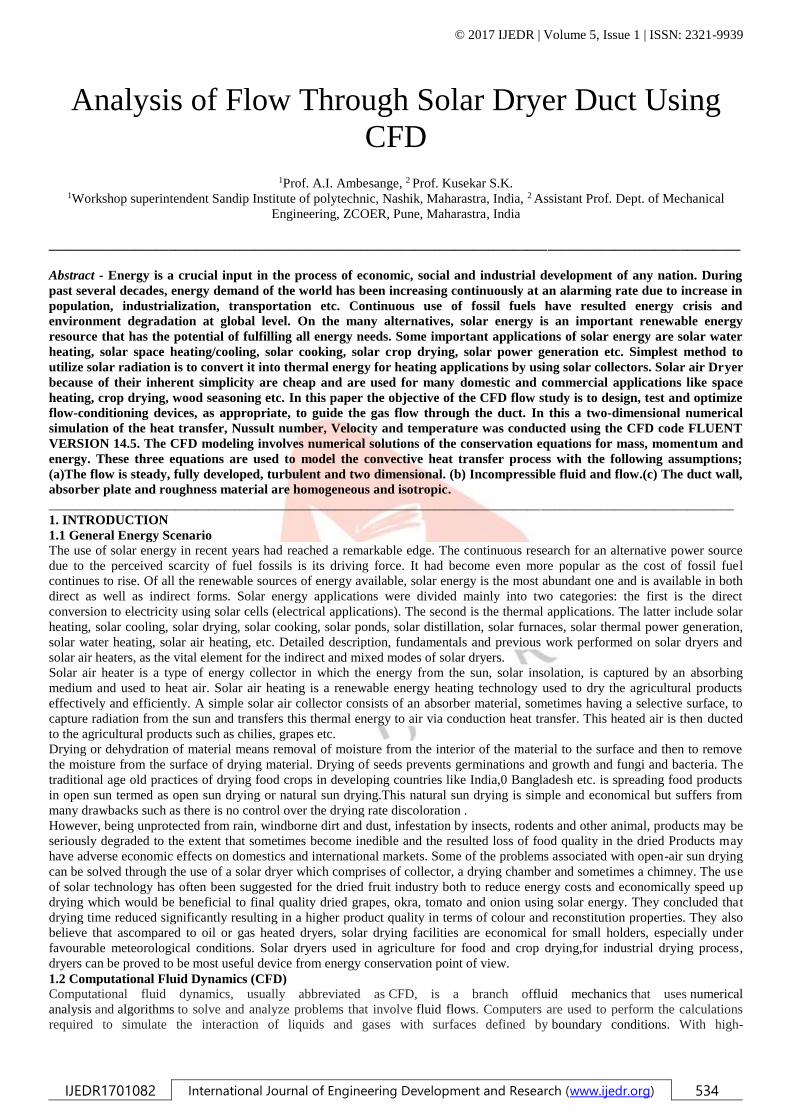
Meshing of Model:
Fig 8 : Meshed Geometry
TEST 1 DUCT WITHOUT TRAY CFD RESULT
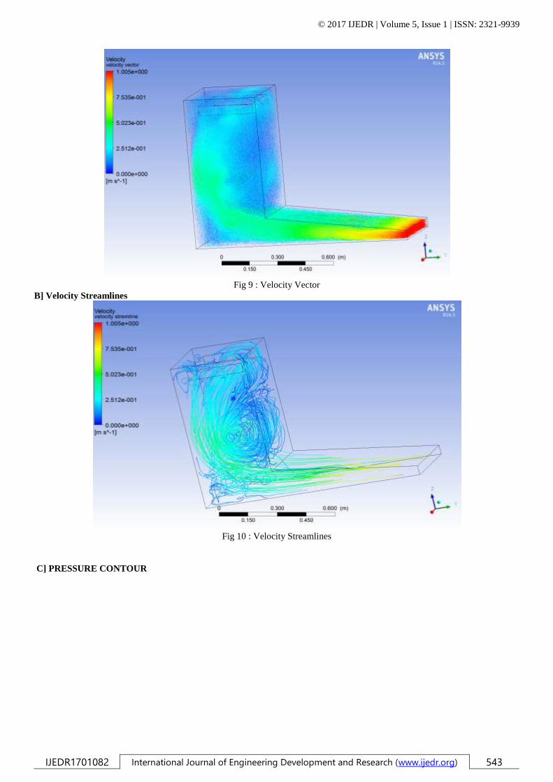
A] Velocity Vector
© 2017 IJEDR | Volume 5, Issue 1 | ISSN: 2321-9939
IJEDR1701082 International Journal of Engineering Development and Research (www.ijedr.org) 543
Fig 9 : Velocity Vector
B] Velocity Streamlines
Fig 10 : Velocity Streamlines
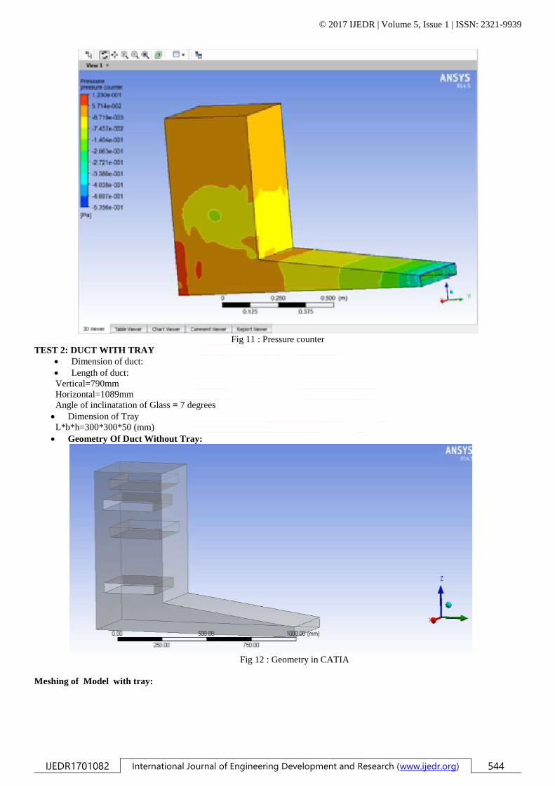
C] PRESSURE CONTOUR
© 2017 IJEDR | Volume 5, Issue 1 | ISSN: 2321-9939
IJEDR1701082 International Journal of Engineering Development and Research (www.ijedr.org) 544
Fig 11 : Pressure counter
TEST 2: DUCT WITH TRAY
Dimension of duct:
Length of duct:
Vertical=790mm
Horizontal=1089mm
Angle of inclinatation of Glass = 7 degrees
Dimension of Tray
L*b*h=300*300*50 (mm)
Geometry Of Duct Without Tray:
Fig 12 : Geometry in CATIA
Meshing of Model with tray:

© 2017 IJEDR | Volume 5, Issue 1 | ISSN: 2321-9939
IJEDR1701082 International Journal of Engineering Development and Research (www.ijedr.org) 545
Fig 13 : Meshed Geometry With Tray
DUCT WITH TRAY CFD RESULT
D] Velocity Vector
Fig 14 : Velocity Vector
E] Velocity streamlines:
© 2017 IJEDR | Volume 5, Issue 1 | ISSN: 2321-9939
IJEDR1701082 International Journal of Engineering Development and Research (www.ijedr.org) 546
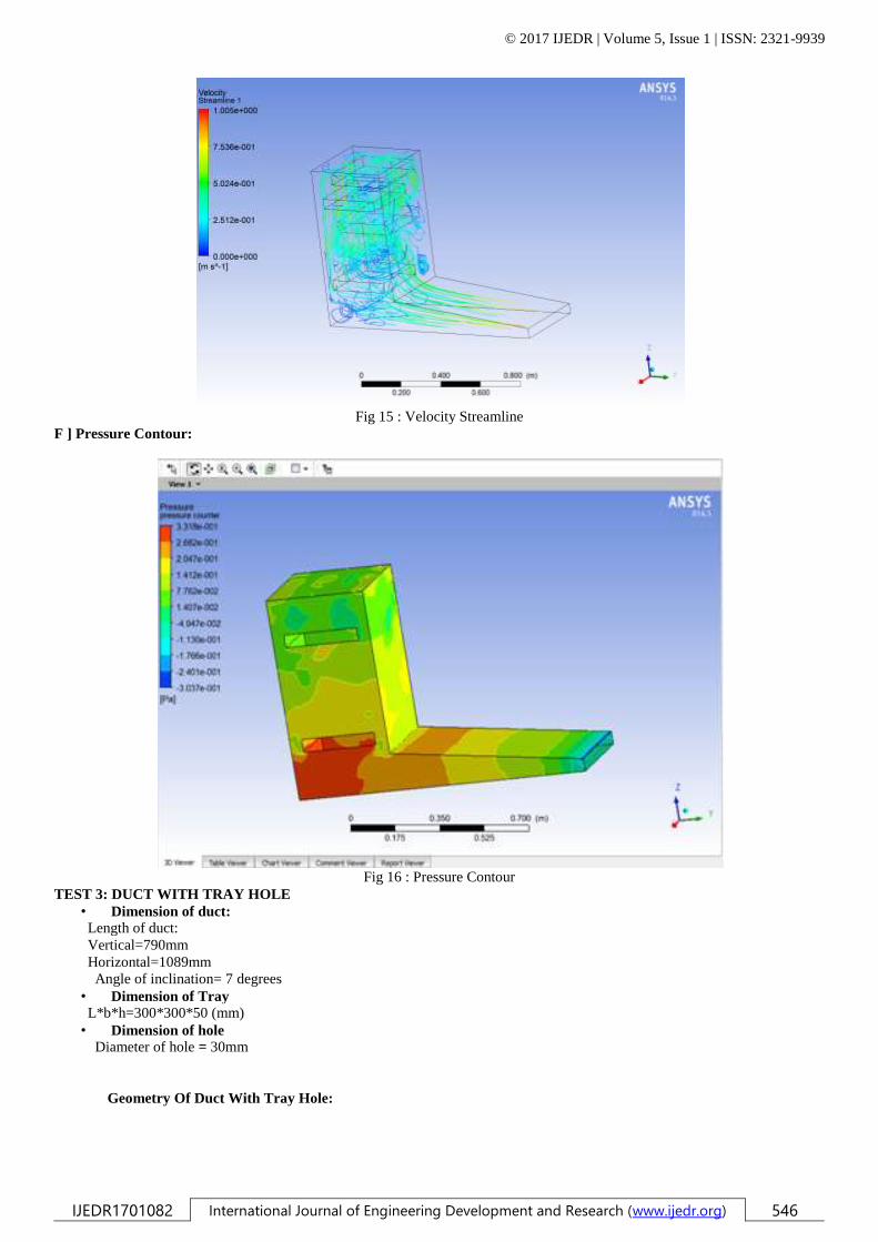
Fig 15 : Velocity Streamline
F ] Pressure Contour:
Fig 16 : Pressure Contour
TEST 3: DUCT WITH TRAY HOLE
• Dimension of duct:
Length of duct:
Vertical=790mm
Horizontal=1089mm
Angle of inclination= 7 degrees
• Dimension of Tray
L*b*h=300*300*50 (mm)
• Dimension of hole
Diameter of hole = 30mm
Geometry Of Duct With Tray Hole:

© 2017 IJEDR | Volume 5, Issue 1 | ISSN: 2321-9939
IJEDR1701082 International Journal of Engineering Development and Research (www.ijedr.org) 547
Fig 17 : Geometry Of Duct With Tray Hole
Meshing of Model with TrayWith Hole:
Fig 18 : Meshing of Model with Tray Hole
DUCT WITH TRAY HOLE CFD RESULT
F] Velocity Vector

© 2017 IJEDR | Volume 5, Issue 1 | ISSN: 2321-9939
IJEDR1701082 International Journal of Engineering Development and Research (www.ijedr.org) 548
Fig 19 : Velocity Vector
G] Velocity Streamlines
Fig 20 : Velocity Streamlines
H] Pressure Counter

© 2017 IJEDR | Volume 5, Issue 1 | ISSN: 2321-9939
IJEDR1701082 International Journal of Engineering Development and Research (www.ijedr.org) 549
Fig21 : Pressure Contour
7. RESULTS
7.1. ANALYSIS OF SOLAR DRYER DUCT WITH TRAY HOLE
A] Boundary conditions:
1] Inlet:-
Temperature -308 Kelvin
Velocity Of Air- 1 m/s
2] Glass:-
Radiation Module
Semitransparent Glass
3] Tray:-
Radiation Module
Absorbtivity = 0.8
4] Module Used:
Energy & Solar Radiation Module
5] Material :
Aluminum
6] Outlet: Atmospheric Pressure
B] SOLUTION
1. Modeling- CATIA V5R20
2. Pre-processer- ICEM CFD
3. Processer- Fluent
4. Post Processer- CFD Post
C] CATIA Model
© 2017 IJEDR | Volume 5, Issue 1 | ISSN: 2321-9939
IJEDR1701082 International Journal of Engineering Development and Research (www.ijedr.org) 550
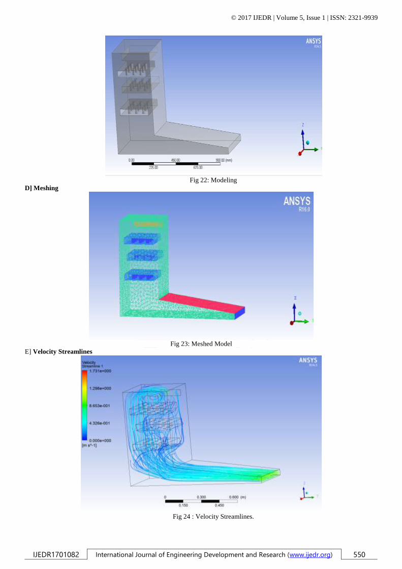
Fig 22: Modeling
D] Meshing
Fig 23: Meshed Model
E] Velocity Streamlines
Fig 24 : Velocity Streamlines.
© 2017 IJEDR | Volume 5, Issue 1 | ISSN: 2321-9939
IJEDR1701082 International Journal of Engineering Development and Research (www.ijedr.org) 551
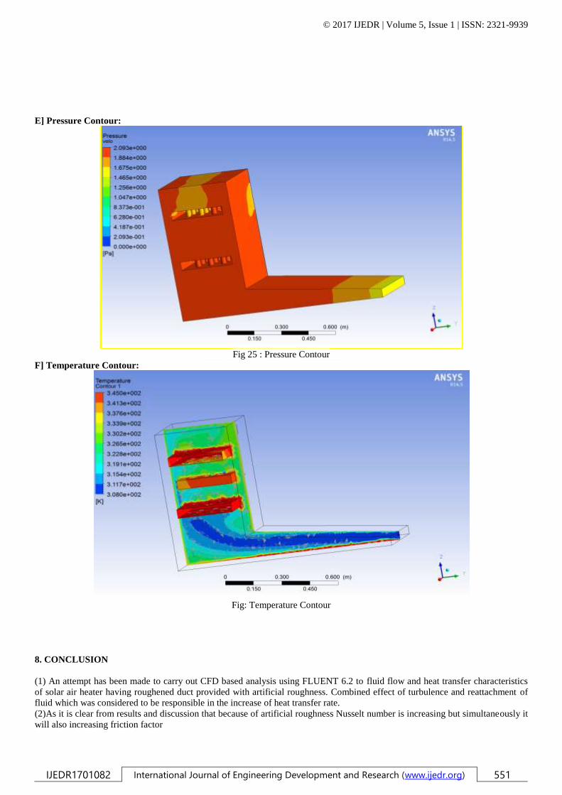
E] Pressure Contour:
Fig 25 : Pressure Contour
F] Temperature Contour:
Fig: Temperature Contour
8. CONCLUSION
(1) An attempt has been made to carry out CFD based analysis using FLUENT 6.2 to fluid flow and heat transfer characteristics
of solar air heater having roughened duct provided with artificial roughness. Combined effect of turbulence and reattachment of
fluid which was considered to be responsible in the increase of heat transfer rate.
(2)As it is clear from results and discussion that because of artificial roughness Nusselt number is increasing but simultaneously it
will also increasing friction factor

© 2017 IJEDR | Volume 5, Issue 1 | ISSN: 2321-9939
IJEDR1701082 International Journal of Engineering Development and Research (www.ijedr.org) 552
(3)Heat transfer is also an increase because of increase in temperature .Trapezoidal rib is mainly responsible for increase in
temperature.
(4)There is no doubt that a major focus of CFD analysis of solar air heater is to enhance the design process that deals with the heat
transfer and fluid flow.
5. REFERANCES
[1] Akinola A. Adeniyi, Abubakar Mohammed, Kehinde Aladeniyi, “ Analysis of a Solar Dryer Box with Ray Tracing CFD
Technique” International Journal of Scientific & Engineering Research Volume 3, Issue 10, October-2012.
[2] S. D. Rajkotia, V. H. Modi, “Performance Improvement of Solar Dryer, Ijsr - International Journal Of Scientific Research”.
[3] C.V.Papade, M.A.Boda, “Design & Development of Indirect Type Solar Dryer with
Energy Storing Material” International Journal of Innovative Research in Advanced Engineering (IJIRAE) ISSN: 2349-2163
Volume 1 Issue 12 (December 2014).
[4] Sandeep Lutade, Dr. S.B. Thombre, “A Cfd Analysis Of Air Flow In A Stationary Drum Partially Filled With Solid Material”
International Journal Of Research In Aeronautical And Mechanical Engineering.
[5] Prof. P.W.Ingle, Dr. A. A. Pawar, Prof. B. D. Deshmukh, Prof. K. C. Bhosale,’’
CFD Analysis Of Solar Flat Plate Collector’’ International Journal of Emerging Technology and Advanced Engineering
[7] M. T. Madhav and M. R. Malin “The numerical simulation of fully developed
duct flowsAppl. Math. Modelling, 1997, Vol. 21, August.
[8] Ze-gao YIN*1, Xian-wei Cao1, Hong-da SHI1, Jian MA2 “Numerical simulation of flow past circular duct” Water Science
and Engineering, Jun. 2010, Vol. 3, No. 2, 208-216.
[9] K.J. Chuaand S.K.“ChouLow-cost drying methods fordevelopingcountries” Trends in Food Science & Technology 14 (2003)
519–528.
[10] Madhlopa, A. and Ngwalo G. “convective solar dryer with a wood waste backup heater for dehydration of food”University
of Malawi – The Polytechnic, Private Bag 303,Chichiri, Blantyre 3.