Embed Size (px)
Citation preview
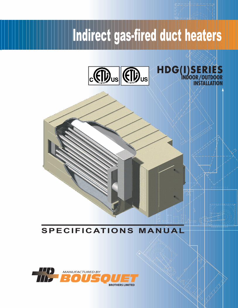
SPECIFICATIONS MANUAL
HDG(I)SERIESINDOOR/OUTDOOR
INSTALLATION
Indirect gas-fired duct heaters

TABLE OF CONTENTS
Description.................................................................................................... 4
Applications...................................................................................................4
Selection criteria ........................................................................................... 5
Installation guidelines..................................................................................... 6
Selection table................................................................................................ 7
Dimensions..................................................................................................... 8
Pressure drop through heat exchanger............................................................10
Options....................................................................................................... 12
Remote control panel (optional)..................................................................... 13
Gas piping.................................................................................................. 14
Characteristics............................................................................................. 15
Typical specifications.................................................................................... 16
The features, illustrations and description in this document were, to ourknowledge, accurate at the time they were approved for printing. Wereserve the right to change or stop offering some features as well as stopproducing a given model without prior notice and commitment on our part.
3

The HDG(I) indirect gas-fired duct heaters manufactured by BOUSQUET are sturdy and of industrial quality; theyare certified for both indoor and outdoor installation and designed to serve as a heating element in ventilationsystems. They operate with a minimum thermal efficiency of 80% and use natural gas as fuel. The capacitiesavailable range from 200 to 5000 MBH (from 59 to 1464 kW) and from 1800 to 90,000 SCFM (from 850 to42,475 l/s) of air at temperature differences of 50°F to 100°F (28°C to 56°C), which enables flexibility of usefor multiple applications.
The multiple pass heat exchanger comprises a primary drum and secondary tubes made of 304L seriesstainless steel requiring no thermal treatment to prevent the cracking of welded joints. In addition, 300 seriesstainless steel is known for its great resistance to corrosion and high temperatures, which increases the servicelife of the unit. The exchanger is equipped with access panels for the inspection and cleaning of the tubes. It isinstalled as to enable the thermal expansion that occurs during the heating cycles of the unit. The forced draftand high gas modulation burner with a 20:1(minimum) turndown ratio offers optimal heat transfer on allthe surfaces of the exchanger while maintaining optimal combustion efficiency through the entire range ofcapacity.
The support frame of the unit is sturdy and consists of welded U-shaped steel channels. The sides and top areof 2-inch thick double wall construction, with maximum 20-inch wide panels made of 18 gauge satin finish steelwith double folded edges for structural rigidity; the liner is made of 22 gauge G90 galvanized steel. The unit isinsulated with 2-inch thick high temperature insulation with a density of 1.5lb/ft3. For outdoor installation, aweatherproof cabinet is required to enclose the burner, gas piping, controls and electrical components. The outersurfaces of the unit are treated with a phosphate cleaner-conditioner and painted with one coat of anticorrosiveepoxy primer exceeding the Canadian (type 1-GP-40) and American (type TT-P-636 D) standards for salt mistand humidity. The finish is ensured with first quality high performance alkyd resin enamel. All HDG(I) ductheaters are cETLus approved and are certified according to standards CAN/CGA3.2 and UL 795.
• Fresh air compensation
- Apartment building corridors
- Schools
- Hospitals
- Industries
• Industrial and commercial warm air heating systems• Ventilation / make-up air systems • Industrial processes
4
DESCRIPTIONDESCRIPTION
APPLICATIONSAPPLICATIONS
5
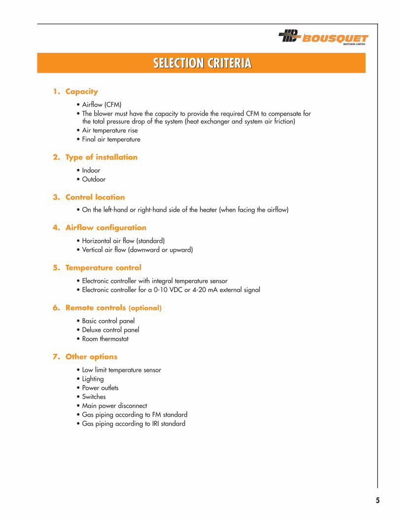
1. Capacity
• Airflow (CFM)• The blower must have the capacity to provide the required CFM to compensate for
the total pressure drop of the system (heat exchanger and system air friction)• Air temperature rise• Final air temperature
2. Type of installation
• Indoor• Outdoor
3. Control location
• On the left-hand or right-hand side of the heater (when facing the airflow)
4. Airflow configuration
• Horizontal air flow (standard)• Vertical air flow (downward or upward)
5. Temperature control
• Electronic controller with integral temperature sensor• Electronic controller for a 0-10 VDC or 4-20 mA external signal
6. Remote controls (optional)
• Basic control panel• Deluxe control panel• Room thermostat
7. Other options
• Low limit temperature sensor• Lighting• Power outlets• Switches• Main power disconnect• Gas piping according to FM standard• Gas piping according to IRI standard
SELECTION CRITERIASELECTION CRITERIA

6
INSTALLATION GUIDELINESINSTALLATION GUIDELINES
The installer of a duct heater such as the HDG(I) must follow certain rules in order to comply with thecodes governing gas equipment. Here are some recommendations:
• The blower must be installed upstream of the duct heater so that it is submitted to positiveair pressure.
• The final air temperature should be controlled by a duct thermostat located downstreamof the duct heater.
• When gas pressure exceeds 1/2 psig (3.5kPa), a high pressure regulator with the samecapacity as the burner must be supplied and installed by the contractor. This regulatormust have the capability to regulate the pressure with a modulating turndown ratio of40:1.
• Allow for sufficient clearance around the unit to enable its installation and maintenance.
For indoor installation,
• all bleed valves and regulator vents must be individually connected to the exterioraccording to code CGA-B149 or other codes in effect;
• the chimney must satisfy the following requirements:• have double walls• be certified for positive pressure units (type PS)• be ULC/UL certified;
• ensure that there is enough air for the combustion in the room where the duct heater isinstalled (refer to code in effect);
• ensure that the combustion air is clean and free of dust or corrosive material that couldreduce the service life of the unit.
For chimney and breeching dimensions, consult the manufacturer.
For any other information related to the installation of the HDG(I) duct heaters, refer to theinstallation and service manual pertaining to these units.
7
MBTU/H
250
375
438
500
625
688
813
938
1063
1250
1563
1875
2188
2500
3125
3750
4375
5000
6250
kW
73
109
128
146
183
201
238
275
311
366
458
549
641
732
915
1098
1281
1464
1830
MBTU/H
200
300
350
400
500
550
650
750
850
1000
1250
1500
1750
2000
2500
3000
3500
4000
5000
kW
59
88
102
117
146
161
190
220
249
293
366
439
512
586
732
878
1025
1171
1464
SCFM3
1860-3710
2780-5560
3250-6480
3710-7410
4630-9260
5100-10190
6020-12040
6950-13890
7870-15740
9260-18520
11580-23150
13890-27780
16210-32410
18520-37040
23150-46300
27780-55560
32410-64820
37040-74080
46300-92600
l/s
878-1751
1312-2624
1534-3058
1751-3497
2185-4370
2407-4809
2841-5682
3280-6555
3714-7428
4370-8740
5465-10926
6555-13111
7650-15296
8740-17481
10926-21851
13111-26221
15296-30592
17481-34962
21851-43702
Burner capacity1 Net capacity Airflow3
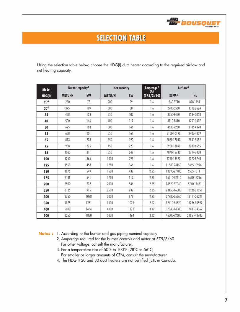
Using the selection table below, choose the HDG(I) duct heater according to the required airflow andnet heating capacity.
Notes : 1. According to the burner and gas piping nominal capacity2. Amperage required for the burner controls and motor at 575/3/60
For other voltage, consult the manufacturer.3. For a temperature rise of 50˚F to 100˚F (28˚C to 56˚C)
For smaller or larger amounts of CFM, consult the manufacturer.4. The HDG(I) 20 and 30 duct heaters are not certified CETL in Canada.
Model
HDG(I)
204
304
35
40
50
55
65
75
85
100
125
150
175
200
250
300
350
400
500
(575/3/60)
1.6
1.6
1.6
1.6
1.6
1.6
1.6
1.6
1.6
1.6
1.6
2.25
2.25
2.25
2.25
2.25
2.62
3.12
3.12
Amperage2
(A)
SELECTION TABLESELECTION TABLE
8
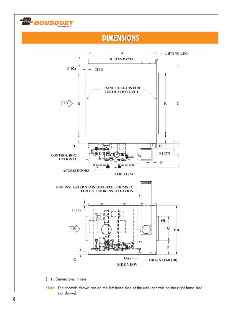
( ) : Dimensions in mm
Notes: The controls shown are on the left-hand side of the unit (controls on the right-hand sidenot shown).
DIMENSIONSDIMENSIONS

9
58414053621
10-1/8121830341
1/21
1544 lbs
HDG(I) 20-30-35
ABBCDGLMNPQRT
Ø GAS 1
Ø VENT2.3
Ø BLEED VALVE3
WEIGHT
inches mm14731041101612776152533257305457762864251325
700 kg
58415453621
10-5/8121844341
1/21
1823 lbs
HDG(I) 40-50-55
147310411016127761525332703054571118864251325
827 kg
58417473821
9-3/4121860341
1/21
2282 lbs
HDG(I) 65-75
147310411016178762035332483054571524864251325
1035 kg
674878938
24-1/210
12 1/22460321
1/21
2875 lbs
HDG(I) 85
170212191981229762036222543186101524813251325
1304 kg
inches mm674878938
24-1/210
12-1/2246032
1-1/21/2
12875 lbs
HDG(I) 100
170212191981229762036222543186101524813381325
1304 kg
inches mm inches mm inches mm
Notes : 1. With an inlet gas pressure of 14 inches of water (3.5kPa)2. Outdoor installation only3. The bleed valve (IRI option) and regulator vents must be piped separately to
the outdoors.
DIMENSIONSDIMENSIONS
746298
8-1/24832
9-5/820248132
1-1/21/2
14122 lbs
HDG(I) 125-150-175
ABBCDGLMNPQRT
Ø GAS 1
Ø VENT2.3
Ø BLEED VALVE3
WEIGHT
inches mm1880157524892161022038132445086102057813381325
1870 kg
8074108641038
10-1/226249636
1-1/21/2
14827 lbs
HDG(I) 200-250
2032188027431521022549652676606102438914381325
2189 kg
10677150951040
12-1/82824132362
1/21
7203 lbs
HDG(I) 300-350
26921956381022912725410163087116103353914501325
3267 kg
10683150951243
11-1/83124132393
3/41-1/2
7295 lbs
HDG(I) 400
26922108381022912730510922837876103353991751938
3309 kg
inches mm10689150951246
11-1/83424132393
3/41-1/2
7743 lbs
HDG(I) 500
26922261381022912530511682838646103353991751938
3512 kg
inches mm inches mm inches mm
10
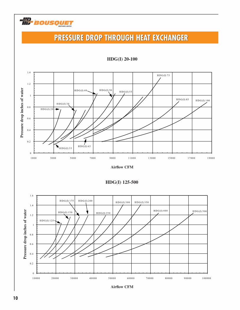
PRESSURE DROP THROUGH HEAT EXCHANGERPRESSURE DROP THROUGH HEAT EXCHANGER
HDG(I) 20-100
Airflow CFM
Pre
ssur
e dr
op in
ches
of
wat
erP
ress
ure
drop
inch
es o
f w
ater
Airflow CFM
HDG(I) 125-500
11
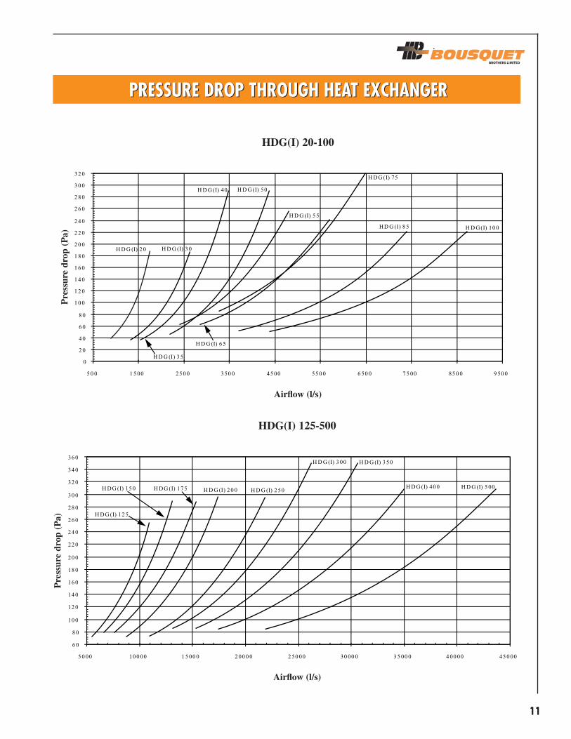
PRESSURE DROP THROUGH HEAT EXCHANGERPRESSURE DROP THROUGH HEAT EXCHANGER
HDG(I) 20-100
HDG(I) 125-500
Pre
ssur
e dr
op (
Pa)
Pre
ssur
e dr
op (
Pa)
Airflow (l/s)
Airflow (l/s)

12
OPTIONSOPTIONS
Marine lighting fixture
Display S7800A1035
Annunciator S7830A1005
Heat exchanger for vertical airflow

13
Note : Refer to the manufacturer for other arrangement or feature.
REMOTE CONTROL PANEL (optional)REMOTE CONTROL PANEL (optional)
Basic Panel
Standard equipment:• Off-blower-burner switch• Blower indicating light• Burner indicating light• Connecting terminal block
Optional equipment:• Temperature selector (shipped separately)
Deluxe panel
Standard equipment:• Blower on-off switch• Burner on-off switch• Blower indicating light• Burner indicating light• Flame failure alarm light• Connecting terminal block
Optional equipment:• Discharge air low limit light• Clogged filter light• High gas pressure light• Low gas pressure light• Purge cycle completed light• Temperature selector (integrated)• Key lock

14
COMPONENTS
1234
567891011
121314
PILOT PIPING Manual shut-off valveGas pressure regulatorAutomatic shut-off valveManual ignition cockMAIN BURNER PIPINGPressure regulatorAutomatic quick-closing shut-off valveAutomatic slow-opening and quick-closing shut-off valveManual ignition cock1/8-inch diameter test portPiping unionModulating valve supplied with burnerOPTIONSLow gas pressure switch (required for FM, IRI and pressure in excess of 1/2 psig)Normally open automatic vent valve (required for IRI)High gas pressure switch (required for FM, IRI and pressure in excess of 1/2 psig)
DESCRIPTIONS
GAS PIPINGGAS PIPING

15
STANDARD CHARACTERISTICS:
• CETLUS certified• Natural gas• GP Combustion burner (20:1 modulation)• Heat exchanger with 304L stainless steel drum and tubes• Inlet gas pressure of 14 inches of water (3.5kPa)• Main power supply (575 volts/3 phases/60 cycles)• Connecting terminal block• All the electric and mechanical components required for the proper operation of the unit• Flame rod detector• Pre-purge period • All safety controls• Satin finish steel (18 gauge) outer panels coated with an enamel based paint and G90
galvanized steel (22 gauge) inner walls• 2-inch thick (51 mm) high temperature insulation with a 1.5lb/ft3 density • Lifting lugs on both sides of the unit for easy handling and installation • Access panel to the exchanger tubes (for cleaning purposes)• Drain• Burner automatic valve interlock • Supply air temperature controller
OPTIONAL CHARACTERISTICS:
• Electric power supply (208, 460 volts/3 phases/60 cycles)• High gas pressure regulator• MAXON burner (10:1 modulation)• Propane gas• Heat exchanger with 316L stainless steel drum and tubes • Gas piping to FM or IRI requirement• Ultra-violet flame detector• Main power supply disconnect with or without fuses• Controls and wiring required to interface with a centralized building automation system• Modulation controller with 0-10 VDC or 4-20 mA signal from a central building automation system• Room thermostat • 120-volt electrical outlet• Exchanger for vertical air flow
Note : Refer to manufacturer for any other options.
CHARACTERISTICSCHARACTERISTICS

16
GENERAL
Supply and install a Bousquet model HDG(I)_____ indirect gas-fired duct heater operating onnatural gas for indoor (outdoor) installation. The manufacturer must be accredited by the CWB tocertify that he complies with standard CSA W47.1 regarding all types of welds including those on astainless steel heat exchanger.
PERFORMANCE
The duct heater will have the capacity to heat _________ CFM of standard air from _____°F to_____°F, for a net heat output of__________ MBH at a minimum combustion efficiency of 80%. Thefuel used will be natural gas at an inlet pressure of _____ psig. The air pressure drop shall not exceed_____ inches of water.
UNIT CONSTRUCTION
The support frame will be made of welded U-shaped structural steel. The sides and top will be of2-inch thick double wall construction, with maximum 20-inch wide panels made of 18 gauge satinfinish steel with double folded edges for structural rigidity; the liner will be made of 22 gauge G90galvanized steel. The unit will have 2-inch thick high temperature insulation with a density of1.5lb/ft3. The outer surfaces of the unit will be treated with a phosphate cleaner-conditioner andpainted with one coat of anticorrosive epoxy primer exceeding the Canadian (type 1-GP-40) andAmerican (type TT-P-636 D) standards for salt mist and humidity. The finish will be ensured with firstquality high performance alkyd resin enamel applied at the plant. For outdoor applications, all thecontrols and piping will be installed inside a weatherproof cabinet with a full-sized access door foreasy maintenance.
HEAT EXCHANGER
The multiple pass heat exchanger will consist of a primary drum and secondary tubes, entirely madeof 304L stainless steel requiring no thermal treatment to prevent the cracking of welded joints andproviding great resistance to corrosion and high temperatures, for longer service life of the unit. Theexchanger will be equipped with access panels for tube inspection and cleaning. 400 series stainlesssteel, aluminized steel and carbon steel heat exchangers are not acceptable.
TYPICAL SPECIFICATIONSTYPICAL SPECIFICATIONS

17
BURNER AND GAS PIPING
The burner will be of a forced draft type, factory-installed on the exchanger with all gas piping andcontrol wiring required for the proper operation of the unit.
The gas pilot piping will be equipped with an electronic spark ignitor, a pressure regulator, manualand automatic shut-off valves as well as a manual ignition cock. The gas supply piping to theburner will include a pressure regulator, manual shut-off valve, automatic quick-closing shut-off valve,automatic slow-opening valve, manual ignition cock, test ports and modulating valve. The burner andgas piping assembly will have a modulating turndown ratio of at least 20:1.
BURNER CONTROL MODE
• G1: A temperature sensor with adjustable set point is installed in the air discharge tomaintain the desired final temperature.
• G2: A temperature sensor with adjustable set point is installed in the air discharge tomaintain the desired final temperature. Upon a demand for heating from the roomthermostat, the burner modulates to satisfy the heating needs of the room.
• Other
REMOTE CONTROL PANEL (optional)
A remote control panel will be supplied by the manufacturer to turn the unit on or off from a remotelocation. It will be equipped with a blower/burner on-off switch and indicating lights.
CERTIFICATION
All HDG(I) heaters must be cETLus approved and certified according to standards CAN/CGA3.2 andUL 795.
OPTIONS
The duct heater will be equipped with the following options.
(List other required options.)

2121, Nobel StreetSainte -Julie, Quebec CANADA
J3E 1Z9
Toll-free: 1-800-363-9197Telephone: (514) 874-9050
Fax: (450) 649-8756E-mail: [email protected]
Rev
. 03/0
2 -
Pri
nte
d in C
anada