Embed Size (px)
Citation preview
AND
NASA TECHNICAL NOTE ( NASA TN D-7467
U. S. A. o
rp0 04
I- O
AN EXPERIMENTAL EVALUATION
Gdadp F d t4l
OF METALLIC DIAPHRAGMS FOR e
POSITIVE FUEL EXPULSION IN * H O .. D B1
by William L. Woodruff"
Goddard Space Flight Center
Greenbelt, Md. 20771
NATIONAL AERONAUTICS AND SPACE ADMINISTRATION WASHINGTON, D. C. DECEMBER 1973
https://ntrs.nasa.gov/search.jsp?R=19740005651 2020-05-29T11:52:09+00:00Z

1. Report No. 2. Government Accession No. 3. Recipient's Catalog No.
NASA TN D-74674. Title and Subtitle 5. Report Date
An Experimental Evaluation of Metallic Diaphragms December 1973
for Positive Fuel Expulsion in the Atmosphere Explorer 6. Performing Organization Code
Hydrazine Propulsion Subsystem 7637. Author(s) 8. Performing Organization Repopt No.
William L. Woodruff G-73559. Performing Organization Name and Address 10. Work Unit No.
757-51-09-01Goddard Space Flight Center . Contract or Grant No.
Greenbelt, Maryland 20771
13. Type of Report and Period Covered
12. Sponsoring Agency Name and Address
Technical NoteNational Aeronautics and Space Administration
Washington, D. C. 20546 14. Sponsoring Agency Code
15. Supplementary Notes
16. Abstract
Four Arde conospheroid metallic diaphragms were tested at Goddard Space FlightCenter to evaluate their capability for use in the orbit adjust propulsion subsystem(OAPS) of the Atmosphere Explorer spacecraft. The diaphragms will be used for
positive propellant expulsion and spacecraft center of mass control. A leak-free
cycle life capability of nine reversals was demonstrated. The diaphragms rolledsmoothly from ring to ring in a predictable manner on the first reversal. Varyingamounts of diaphragm cocking and ring skipping were observed on subsequentreversals. The diaphragm pressure differential did not exceed 7 N/cm2 (10 psid)during any reversal. Cycle life capability, reversal mode, and pressure differentialwere not affected by sudden reversals, environmental tests, or 18,000 partial reversals.An expulsion efficiency of approximately 97 percent was demonstrated. The resultsof these tests show that metallic diaphragms can be used as an effective means of
positive fuel expulsion; however, to achieve spacecraft center of mass (c.m.) control,the diaphragm must not be reversed prior to flight.
17. Key Words (Selected by Author(s)) 18. Distribution Statement
Auxiliary systems, Expulsion device,
Propulsion systems Unclassified - Unlimited
19. Security Classif. (of this report) 120. Security Classif. (of this page) 21. No. of Pages 22. PriceDomestic, $2.75
Unclassified Unclassified 12 Foreign, $5.25
*For sale by the National Technical Information Service, Springfield, Virginia 22151.
__

Presented at the Monopropellant Propulsion Specialist Session of the JANNAFPropulsion Meeting, November 28, 1972, New Orleans, Louisiana.
ii

CONTENTS
Page
ABSTRACT . . .. . . . . . . . . . . . . . . . . . . . . .
INTRODUCTION .............. .. ...... 1
TEST PLAN . . . . . . . . . . . . . . . . . . . .. . ... 1
TEST HARDWARE AND SETUP ..... ...... ..... 2
Test Hardware . . . . . . . . . . . . . . . . . . . . . . 2
Test Setup . . . . . . . . . . . . . . . . . . . . . . 3
RESULTS . . . . . . . . . . . . . . . . . . . . .... .. . . 3
Phase 1 . . . . . . . . . . . . . . . . . . . . . . . . 3
Phase 2 . . . . . . . . . . . . . . . . . . . . . . . . 6
CONCLUSION . . . . . ..... ... . . . . . . . . . . 11
ACKNOWLEDGMENTS .............. ...... 11
iii
AN EXPERIMENTAL EVALUATION OF METALLIC DIAPHRAGMS
FOR POSITIVE FUEL EXPULSION IN THE ATMOSPHEREEXPLORER HYDRAZINE PROPULSION SUBSYSTEM
William L. WoodruffGoddard Space Flight Center
INTRODUCTION
This paper reports on the results of a series of tests performed to evaluate the capability of
Arde conospheroid metallic diaphragms. The tests were conducted at NASA Goddard
Space Flight Center (GSFC) during the period of December 1971 through March 1972.
The prime objective was to evaluate the use of metallic diaphragms in propellant tanks as
a means of achieving spacecraft center of mass (c.m.) control. A secondary objective was
to establish the diaphragm cycle life capability and expulsion efficiency. The final ob-
jective was to determine the effect of sudden reversals, launch-level environmental con-
ditions, and 18,000 partial reversals on the diaphragm performance.
One of the significant features of the Atmosphere Explorer spacecraft (AE's C, D, and E)
is that its c.m. must be maintained in a fixed location +± 0.254 cm (±0.100 in.) throughout
its life. Because the AE spacecraft weighs approximately 635 kg (1400 lb), of which
168 kg (370 lb) is propellant (hydrazine), the propellant c.m. must be controlled to con-
trol the spacecraft c.m. Arde metallic diaphragms rolling from ring to ring in a predictable
manner offer a solution to this problem.
The four test diaphragms and the test tank were transferred to NASA/GSFC from NASA
Lewis Research Center (LeRC). The diaphragms were designed and fabricated for NASA
LeRC by Arde, Inc., of Mahwah, New Jersey, under contract NAS 3-12026. The purpose
of that program was to develop high cycle life ring reinforced diaphragms for use in
cryogenic systems.' At the conclusion of the program, four diaphragms, each with a cone
half-angle of 250, remained untested. The diaphragms were then tested at NASA/GSFC
using distilled water as a simulant for the propellant.
TEST PLAN
This test program was carried out in two phases. Phase 1 consisted of repeated reversals of
a diaphragm to establish baseline cycle life capability, reversal mode, pressure drop, and
1 D. Gleich: "Metallic Positive Expulsion Diaphragms." NASA CR-72775. Arde, Inc. Report 46002 (Contract
NAS 3-12026), March 1971.
_2
expulsion efficiency. Phase 2 consisted of subjecting three diaphragms to conditions theymight encounter in flight or during ground handling (sudden reversals, environmentaltests, and 18,000 partial reversals) and determining the effect of these conditions on thediaphragm performance.
TEST HARDWARE AND SETUP
Test Hardware
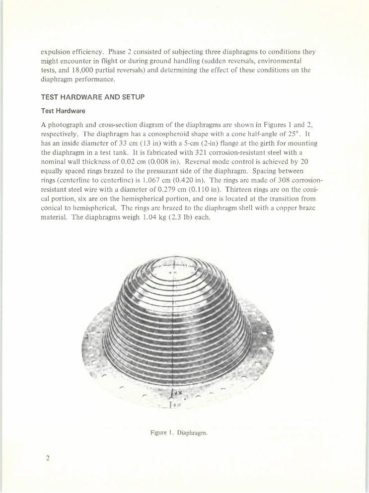
A photograph and cross-section diagram of the diaphragms are shown in Figures 1 and 2,respectively. The diaphragm has a conospheroid shape with a cone half-angle of 25'. Ithas an inside diameter of 33 cm (13 in) with a 5-cm (2-in) flange at the girth for mountingthe diaphragm in a test tank. It is fabricated with 321 corrosion-resistant steel with anominal wall thickness of 0.02 cm (0.008 in). Reversal mode control is achieved by 20equally spaced rings brazed to the pressurant side of the diaphragm. Spacing betweenrings (centerline to centerline) is 1.067 cm (0.420 in). The rings are made of 308 corrosion-resistant steel wire with a diameter of 0.279 cm (0.110 in). Thirteen rings are on the coni-cal portion, six are on the hemispherical portion, and one is located at the transition fromconical to hemispherical. The rings are brazed to the diaphragm shell with a copper brazematerial. The diaphragms weigh 1.04 kg (2.3 lb) each.
Figure 1. Diaphragm.
2

t- 0.020 cm 1.067±0.15 cm (TYP)
321 STAINLESS STEEL308 STAINLESS STEEL
25* WIRE
33 cm 3N
43cm
Figure 2. Diaphragm schematic.
Test Setup
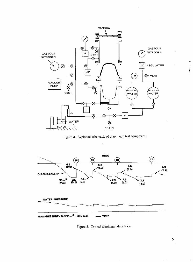
A photograph and schematic diagram of the test setup are shown in Figures 3 and 4,respectively. The lower portion of the test tank has a conospheroid shape correspondingto that of the diaphragm. The upper portion is cylindrical with a glass window for viewingand photographing the diaphragm during an expulsion cycle. The diaphragm is sealed inthe tank with "O" rings and the window is sealed with gaskets. Provision is made forevacuating or pressurizing either side of the diaphragm, supplying distilled water to thepropellant side of the diaphragm, and expelling water through a flowmeter to a scale forweighing. Diaphragm pressure drop was measured during the reversals by means of aDynasciences differential pressure transducer. Data were recorded on a Honeywell 1508visicorder.
RESULTS
Phase 1
Diaphragm S/N 5 was reversed repeatedly until a leak developed. The purpose of this test
was to establish the diaphragm baseline performance in terms of cycle life, reversal mode,pressure drop, and expulsion efficiency.
The diaphragm rings were numbered sequentially from 1 to 20 starting with the ring
nearest the girth. Gaseous nitrogen pressurized to 34 N/cm2 (50 psia) was used as the
pressurant. The water flowrate was adjusted to 6.8 g/s (0.015 lb/s) to simulate thenominal propellant flowrate in the spacecraft. Approximately 50 min were required to
complete each odd-number reversal (1, 3, 5, and so on). The diaphragm was restored toits initial condition, on the even-number reversals (2, 4, 6, and so on) by the introduction
of water into the propellant side of the diaphragm at 34 N/cm2 (50 psia). Because the
even number reversals do not represent a propellant expulsion cycle, they will not be dis-
cussed further in this document.
3

Figure 3. Test equipment.
Reversal number 1 was accomplished without incident. The reversal began at the girth,next to ring number 1, and rolled smoothly from ring to ring, expelling water in a pre-dictable manner. In general, the odd-number reversals begin at the girth and the even-
number reversals begin at the apex. The diaphragm pressure drop was less than 7 N/cm 2
(10 psid) until it was fully reversed. At the end of the reversal, the pressure differentialwas allowed to increase to 24 N/cm2 (35 psid). A portion of a typical data trace is shownin Figure 5.
The third reversal began at the girth and reversed smoothly through ring number 7. Atthat point the dome (the small region above ring 20) reversed. The reversal continued atring 8 and reversed normally to ring 14. At that point, the diaphragm stopped reversing onone side but continued to reverse to ring 16 on the other side, causing the diaphragm tocock. At this point the reversal stopped at ring 16 while the other side reversed to ring 16,straightening out the diaphragm. From that time the reversal was accomplished withoutcocking. Similar reversal patterns were obtained on the other odd-number reversals.
4
WINDOW
GASEOUS
GASEOUS P NITROGEN
NITROGEN
REGULATOR
VENT
VACUUM
VENT WATER WATER
WATER
SCALE DRAIN
Figure 4. Exploded schematic of diaphragm test equipment.
RING
6.9 6.2 I I(10.0) (9.0) 5.5 49
(7.9)
DIAPHRAGM AP
N/cm2 3.5 4 2.9 3.5 2.8(Psid) (5.2) (5.0) (4.2) (5.2) (4.0)
WATER PRESSURE
GAS PRESSURE=34.9N/cm2 (50.5 psia) TIME
Figure 5. Typical diaphragm data trace.

A leak rate of 5.5 X 10-s cubic centimeters of gaseous helium per second was measuredwith a CEC leak detector at the end of reversal number 8. This leak rate increased to 1.9cm 3 of gaseous nitrogen per second at the end of reversal number 9. This pinhole leakgrew to a crack 0.79 cm (5/16 of an inch) in length during reversal number 10. The leakoccurred next to ring 3. Approximately 16.7 kg (36.9 lb) of water was expelled duringthe reversals, and an additional 0.41 kg (0.9 lb) was drained from the tank, yielding anexpulsion efficiency of 97.6 percent.
Phase 2
Sudden Reversals
Diaphragms in the AE propellant tanks will not be cycled prior to flight unless an accidentoccurs during ground handling that results in a partial or full reversal. The procedure forloading fluids (propellant or simulant) in the tanks is to evacuate the pressurant side andthen the propellant side and then to slowly add the propellant. In this state, if the vacuumis lost on the pressurant side, the diaphragm will experience a sudden reversal. The purposeof this test was to determine the effects of two sudden reversals upon diaphragm cycle lifecapability, reversal mode, pressure drop, and expulsion efficiency.
Diaphragm S/N 4 was used for the sudden reversal tests. The procedure was to evacuatethe pressurant side of the diaphragm to 0.14 N/cm' (0.2 psia) and then the propellant sideto 0.14 N/cm 2 (0.2 psia). At this point a hand valve was opened as rapidly as possible,venting the pressurant side to atmospheric pressure. The reversal was completed in 20.5 s.The diaphragm reversed in a series of six steps, each step consisting of three to four rings.When the pressure increased to 3.2 N/cm' (4.7 psia) (in approximately 6 s), the diaphragmrapidly reversed through the first step and the pressure dropped to 1.7 N/cm 2 (2.5 psia).When the pressure increased to 3.4 N/cm' (5.0 psia), the diaphragm reversed through thenext step, and so on. The second sudden reversal was completed in 17 s. Diaphragmcocking did not occur during the sudden reversals.
Following the sudden reversals, the diaphragm was subjected to cycle life tests. Diaphragmcocking and ring skipping were observed during these reversals. A pinhole leak was ob-served between rings 3 and 4 during reversal 10. The pressure drop across the diaphragmand the expulsion efficiency were approximately the same value as obtained with diaphragmS/N 5.
Environmental Tests
Arde tank/metallic diaphragm interfaces are designed such that the diaphragm stiffenerrings bottom against the tank shell when the tank is fully loaded with propellant. Thismeans that the pressurant would normally be stored in external tanks. However, becauseof space and weight limitations on the AE spacecraft, it is desirable to store the pressurantin the propellant tanks. To accomplish this the diaphragm must be partially reversed,providing the required ullage volume on the pressurant side of the diaphragm. In the case
6

of the AE spacecraft, the propellant tanks have a total volume of 33,600 cm (2050 in3 )
with an ullage volume of 5,735 cm 3 (350 in 3 ). This means that the diaphragm is reversed
about 17 percent prior to flight. One of the concerns was that it might be damaged or
distorted during launch-level vibration and acceleration because it is partially reversed and
tilted relative to the launch vehicle thrust axis; as a result, the diaphragm must support
part of the propellant during launch (See Figure 6). The purpose of the following tests
was to determine whether the diaphragm could withstand vibration and acceleration forces
and still perform as required after orbit is achieved.
LAUNCH AXIS
Sc.m.
Figure 6. Schematic diagram of orbit adjust propulsion system.
7

Diaphragm S/N 3 was used for the vibration and acceleration tests. It was installed in the
test tank, loaded with 17.25 kg (38 lb) of distilled water, and pressurized to 34 N/cm2
(50 psia). To simulate the partially reversed AE diaphragm, 2.90 kg (6.4 lb) of water wasexpelled from the tank, reversing the diaphragm about 17 percent. This reversed the
diaphragm to ring 2.
Vibration tests were conducted on the NASA/GSFC Test and Evaluation Division C-210shaker table, which has a total capacity of 135,000 N (30,000 lb). The test tank was
attached to the shaker table via a tilt fixture that was required during the acceleration
tests. Thrust axis tests were conducted first. Initially, a low level (1/2g) sinusoidal sweep5 to 200 Hz) was made as a workmanship check. This was followed by 1-1/2g and 2-1/2gsinusoidal sweeps from 10 to 200 Hz. The two-stage Delta qualification level sinusoidalvibration level is 2-1/2g from 20 to 200 Hz at a sweep rate of two octaves per minute. Therandom vibration input was 0.09 g /Hz (12.8g's rms). This level was maintained for 4 minover the frequency range from 20 to 2000 Hz. Lateral axis vibration tests included sweepsat 1/2g, 1-1/2g, and 8-1/2g. The AE component vibration qualification level is 10g from20 to 2000 Hz. This level could not be achieved because the shaker table was drawing toomuch current due to a heavy test fixture. Random vibration test levels were the same asfor the thrust axis. Examination of the diaphragm after each test showed no damage.
Acceleration tests were conducted on the NASA/GSFC Test and Evaluation Divisionlaunch phase simulator and are summarized in Figure 7. Three acceleration tests wereconducted. The first two tests were at the two-stage Delta qualification level and the thirdwas at the AE qualification level. The diaphragm was tilted at a 450 angle during the firsttest such that the diaphragm was supported by the propellant. (Distilled water was used aspropellant simulant.) An acceleration level of 15-1/2g was applied for a duration of 1 min.During the next test the test tank was inverted so that the diaphragm supported thepropellant simulant. This test was also conducted at 15-1/2g for 1 min. The final testconsisted of having the diaphragm tilted at a 300 angle with the propellant supporting thediaphragm. An acceleration level of 24g was applied for 3 min. This acceleration leveland diaphragm orientation simulates the AE configuration while the spacecraft is beingspin-balanced at 150 rpm. Examination of the diaphragm after each acceleration testshowed no diaphragm damage and no apparent diaphragm movement.
Following completion of the environmental tests, the diaphragm was subjected to cyclelife testing to determine if the cycle life capability, reversal mode, pressure drop, andexpulsion efficiency were adversely affected by environmental testing. In summary, thediaphragm reversed smoothly from ring to ring without cocking on the first and secondreversals. Diaphragm cocking and ring skipping occurred on subsequent reversals. Thediaphragm developed a pinhole leak near ring 2 on the 10th reversal. The pressure dropand expulsion efficiency were about the same level as obtained with the other diaphragms.
8

Partial Reversals
The propellant temperature in the AE spacecraft is expected to vary ±0.560 K(±10 F)from orbit to orbit. Because hydrazine density is a function of temperature, the volume
occupied by the propellant in each tank will vary approximately 41 cm3 (2.5 in3 ) duringeach 2-hr orbital period. This means 4380 partial cycles of the diaphragm (8760 partial
reversals) in a 1-yr spacecraft life. Diaphragm S/N 3 was subjected to 18,000 partial
TEST TANK
WATER , 45
26% rpm
15%g
DIAPHRAGM1.MIN DURATION
WINDOW
CENTRIFUGESPIN AXIS
-26% rpm
15%g
1,MIN DURATION
CENTRIFUGESPIN AXIS
33 rpm
24g
3*MIN DURATION
CENTRIFUGESPIN AXIS
Figure 7. Diaphragm orientation during three acceleration tests.
9
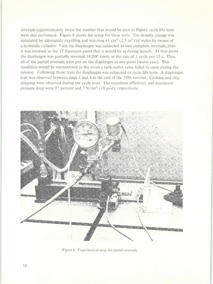
reversals (approximately twice the number that would be seen in flight); cycle life testswere also performed. Figure 8 shows the setup for these tests. The density change wassimulated by alternately expelling and injecting 41 cm3 (2.5 in ) of water by means ofa hydraulic cylinder. First the diaphragm was subjected to two complete reversals; thenit was reversed to the 17.0-percent point that it would be at during launch. At that pointthe diaphragm was partially reversed 18,000 times, at the rate of 1 cycle per 15 s. Thusall of the partial reversals were put on the diaphragm at one point (worst case). Thiscondition would be encountered in the event a tank outlet valve failed to open during themission. Following those tests the diaphragm was subjected to cycle life tests. A diaphragmleak was observed between rings 3 and 4 at the end of the 10th reversal. Cocking and ringskipping were observed during the cycle tests. The expulsion efficiency and maximumpressure drop were 97 percent and 7 N/cm2 (10 psid), respectively.
Figure 8. Experimental array for partial reversals.
10

CONCLUSION
Arde metallic diaphragms reverse smoothly from ring to ring in a predictable manner onthe first reversal, but experience various amounts of cocking and ring skipping on sub-sequent reversals. The pressure drop across the diaphragm remained below 7 N/cm2
(10 psid) until the diaphragm was fully reversed. A cycle life capability of at least ninereversals was demonstrated. The expulsion efficiency was in excess of 97 percent for allreversals. The diaphragm performance was not adversely affected by sudden reversals,environmental tests, or partial reversals. In conclusion, these diaphragms can be used as aneffective means for propellant expulsion, but must not be reversed prior to flight if c.m.control is a spacecraft requirement.
ACKNOWLEDGMENTS
The author gratefully acknowledges the contributions of J.W. Ryland and R.D. Cory forproviding extensive test support. Appreciation is expressed to David Gleich (Arde, Inc.),W.J. Tolson (TRW Systems), D.L. Balzer (RCA Astro Electronics Division), and Ray Lark(NASA LeRC) for reviewing and commenting on the preliminary test plan.
Goddard Space Flight CenterNational Aeronautics and Space Administration
Greenbelt, Maryland April 1973757-51-09-01-51
NASA-Langley, 1973 - 3 11