Embed Size (px)
Citation preview
SIS ( 1CAD ) Misc. Reference Manual Pages SIS ( 1CAD )
NAMEsis – Sequential Interactive System
SYNOPSISsis [options] [file]
DESCRIPTIONSIS is an algorithmic sequential circuit optimization program. SIS starts from a description of a sequen-tial logic macro-cell and produces an optimized set of logic equations plus latches which preserves theinput-output behavior of the macro-cell. The sequential circuit can be stored as a finite state machine oras an implementation consisting of logic gates and memory elements. The program includes algorithmsfor minimizing the area required to implement the logic equations, algorithms for minimizing delay, anda technology mapping step to map a network into a user-specified cell library. It includes all of theoptimization techniques available in MIS, and replaces MIS completely.
SIS can be run in interactive mode accepting commands from the user, or in batch mode reading com-mands from a file or from the command line. If no options are given on the command line, SIS willenter interactive mode. Otherwise, SIS will enter batch mode. When running in batch mode, SIS readsits input from the file given on the command line, or from standard input if no filename is given; outputis directed to standard output, unless -o is used to specify an output filename.
When SIS starts-up, it performs an initial source of the files $SIS/sis_lib/.misrc and $SIS/sis_lib/.sisrc.Typically this defines a standard set of aliases for various commands. Following that the files ˜/.misrc,˜/.sisrc, ./misrc, and ./sisrc are sourced for user-defined aliases at startup.
OPTIONS-c cmdline
Run SIS in batch mode, and execute cmdline. Multiple commands are separated with semi-colons.
-f script Run SIS in the batch mode, and execute commands from the file script.
-t type Specifies the type of the input when running in batch mode. The legal input types are: Berke-ley Logic Interchange Format (-t blif), eqntott(1CAD)-format equation input (-t eqn), KISS2format (-t kiss), Oct Logic View (-t oct), Berkeley PLA Format (-t pla), SLIF format (-t slif),and suppress input (-t none). The default input type is blif.
-T type Specifies the type of the output when running in batch mode. The legal output types are:bdnet(1CAD)-format net-list (-T bdnet), Berkeley Logic Interchange Format (-T blif),eqntott(1CAD)-format equation input (-T eqn), KISS2 format (-T kiss), Oct logic view (-Toct), Berkeley PLA Format (-T pla), SLIF format (-T slif), and suppress output (-T none).The default output type is blif.
-o file Specifies the output file when running in batch mode. For Oct output, this is a string of theform cell:view. The default for the output is the standard output.
-s Suppress sourcing the commands from the standard startup script ($SIS/sis_lib/.misrc and$SIS/sis_lib/.sisrc).
-x For batch mode operation, suppress reading an initial network, and suppress writing an outputnetwork. Equivalent to -t none -T none.
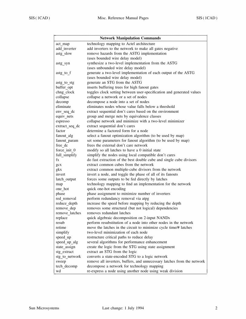
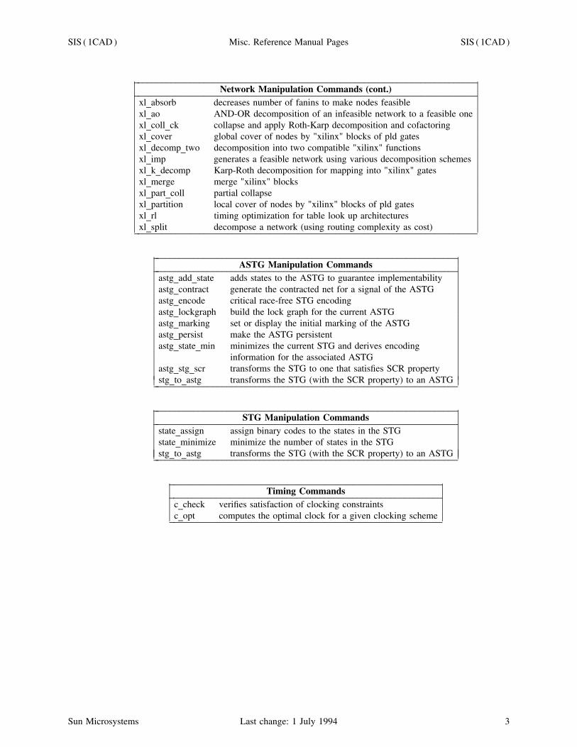
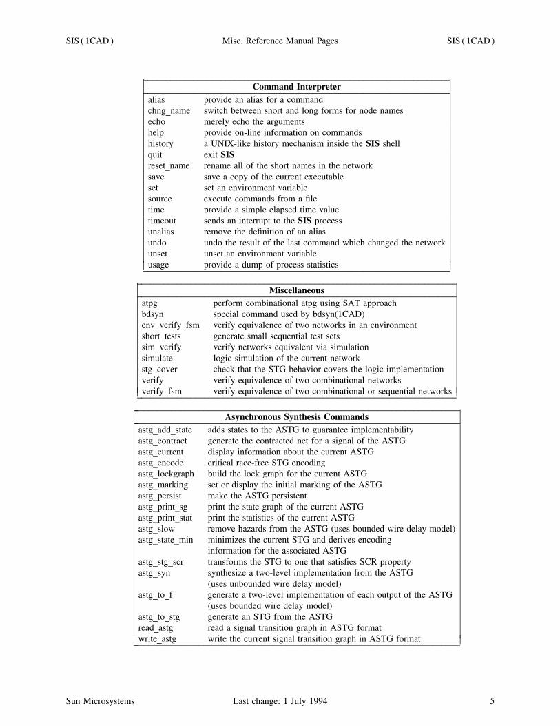
COMMAND SUMMARYAll commands are summarized below according to their function : network manipulation (operations onthe logic-level implementation), ASTG manipulation (operations on the asynchronous signal transitiongraph), STG manipulation (operations on the synchronous state transition graph), input-output, networkstatus, command interpreter, and miscellaneous. The last two tables summarize the newest commandsthat operate on ASTG’s and sequential circuits, respectively.
Sun Microsystems Last change: 1 July 1994 1
SIS ( 1CAD ) Misc. Reference Manual Pages SIS ( 1CAD )
_ ____________________________________________________________________________Network Manipulation Commands_ ____________________________________________________________________________
act_map technology mapping to Actel architectureadd_inverter add inverters to the network to make all gates negativeastg_slow remove hazards from the ASTG implementation
(uses bounded wire delay model)astg_syn synthesize a two-level implementation from the ASTG
(uses unbounded wire delay model)astg_to_f generate a two-level implementation of each output of the ASTG
(uses bounded wire delay model)astg_to_stg generate an STG from the ASTGbuffer_opt inserts buffering trees for high fanout gateschng_clock toggles clock setting between user-specification and generated valuescollapse collapse a network or a set of nodesdecomp decompose a node into a set of nodeseliminate eliminates nodes whose value falls below a thresholdenv_seq_dc extract sequential don’t cares based on the environmentequiv_nets group and merge nets by equivalence classesespresso collapse network and minimize with a two-level minimizerextract_seq_dc extract sequential don’t caresfactor determine a factored form for a nodefanout_alg select a fanout optimization algorithm (to be used by map)fanout_param set some parameters for fanout algorithm (to be used by map)free_dc frees the external don’t care networkforce_init_0 modify so all latches to have a 0 initial statefull_simplify simplify the nodes using local compatible don’t caresfx do fast extraction of the best double cube and single cube divisorsgcx extract common cubes from the networkgkx extract common multiple-cube divisors from the networkinvert invert a node, and toggle the phase of all of its fanoutslatch_output forces some outputs to be fed directly by latchesmap technology mapping to find an implementation for the networkone_hot quick one-hot encodingphase phase assignment to minimize number of invertersred_removal perform redundancy removal via atpgreduce_depth increase the speed before mapping by reducing the depthremove_dep removes some structural (but not logical) dependenciesremove_latches removes redundant latchesreplace quick algebraic decomposition on 2-input NANDsresub perform resubstitution of a node into other nodes in the networkretime move the latches in the circuit to minimize cycle time/# latchessimplify two-level minimization of each nodespeed_up restructure critical paths to reduce delayspeed_up_alg several algorithms for performance enhancementstate_assign create the logic from the STG using state assignmentstg_extract extract an STG from the logicstg_to_network converts a state-encoded STG to a logic networksweep remove all inverters, buffers, and unnecessary latches from the networktech_decomp decompose a network for technology mappingwd re-express a node using another node using weak division_ ____________________________________________________________________________ ⎜⎜
⎜⎜⎜⎜⎜⎜⎜⎜⎜⎜⎜⎜⎜⎜⎜⎜⎜⎜⎜⎜⎜⎜⎜⎜⎜⎜⎜⎜⎜⎜⎜⎜⎜⎜⎜⎜⎜⎜⎜⎜⎜⎜⎜⎜⎜⎜⎜⎜⎜⎜⎜⎜⎜⎜⎜⎜⎜⎜
⎜⎜⎜⎜⎜⎜⎜⎜⎜⎜⎜⎜⎜⎜⎜⎜⎜⎜⎜⎜⎜⎜⎜⎜⎜⎜⎜⎜⎜⎜⎜⎜⎜⎜⎜⎜⎜⎜⎜⎜⎜⎜⎜⎜⎜⎜⎜⎜⎜⎜⎜⎜⎜⎜⎜⎜⎜⎜⎜⎜
Sun Microsystems Last change: 1 July 1994 2
SIS ( 1CAD ) Misc. Reference Manual Pages SIS ( 1CAD )
_ ________________________________________________________________________Network Manipulation Commands (cont.)_ ________________________________________________________________________
xl_absorb decreases number of fanins to make nodes feasiblexl_ao AND-OR decomposition of an infeasible network to a feasible onexl_coll_ck collapse and apply Roth-Karp decomposition and cofactoringxl_cover global cover of nodes by "xilinx" blocks of pld gatesxl_decomp_two decomposition into two compatible "xilinx" functionsxl_imp generates a feasible network using various decomposition schemesxl_k_decomp Karp-Roth decomposition for mapping into "xilinx" gatesxl_merge merge "xilinx" blocksxl_part_coll partial collapsexl_partition local cover of nodes by "xilinx" blocks of pld gatesxl_rl timing optimization for table look up architecturesxl_split decompose a network (using routing complexity as cost)_ ________________________________________________________________________ ⎜
⎜⎜⎜⎜⎜⎜⎜⎜⎜⎜⎜⎜⎜⎜⎜
⎜⎜⎜⎜⎜⎜⎜⎜⎜⎜⎜⎜⎜⎜⎜⎜
_ ________________________________________________________________ASTG Manipulation Commands_ ________________________________________________________________
astg_add_state adds states to the ASTG to guarantee implementabilityastg_contract generate the contracted net for a signal of the ASTGastg_encode critical race-free STG encodingastg_lockgraph build the lock graph for the current ASTGastg_marking set or display the initial marking of the ASTGastg_persist make the ASTG persistentastg_state_min minimizes the current STG and derives encoding
information for the associated ASTGastg_stg_scr transforms the STG to one that satisfies SCR propertystg_to_astg transforms the STG (with the SCR property) to an ASTG_ ________________________________________________________________ ⎜⎜
⎜⎜⎜⎜⎜⎜⎜⎜⎜⎜⎜⎜
⎜⎜⎜⎜⎜⎜⎜⎜⎜⎜⎜⎜⎜⎜
_ ________________________________________________________________STG Manipulation Commands_ ________________________________________________________________
state_assign assign binary codes to the states in the STGstate_minimize minimize the number of states in the STGstg_to_astg transforms the STG (with the SCR property) to an ASTG_ ________________________________________________________________ ⎜⎜
⎜⎜⎜⎜
⎜⎜⎜⎜⎜⎜
_ _________________________________________________________Timing Commands_ _________________________________________________________
c_check verifies satisfaction of clocking constraintsc_opt computes the optimal clock for a given clocking scheme_ _________________________________________________________ ⎜
⎜⎜⎜
⎜⎜⎜⎜
Sun Microsystems Last change: 1 July 1994 3

SIS ( 1CAD ) Misc. Reference Manual Pages SIS ( 1CAD )
_ _______________________________________________________________Input-Output Commands_ _______________________________________________________________
read_astg read a signal transition graph in ASTG formatread_blif read a network in BLIF formatread_eqn read a network in eqntott(1CAD) formatread_kiss read an STG in KISS2 formatread_library read a library description fileread_oct read a network from an Oct Logic viewread_pla read a network in PLA formatread_slif read a network in Stanford Logic Interchange Formatset_delay set delay parameters for primary inputs and outputsset_state set the current state in a sequential circuit to the given statewrite_astg write the current signal transition graph in ASTG formatwrite_bdnet write the current (mapped) network in bdnet(1CAD) formatwrite_blif write the current network in BLIF formatwrite_eqn write the current network in eqntott(1CAD) equation formatwrite_kiss write the STG in KISS2 formatwrite_oct write the current network into an Oct Logic viewwrite_pla write the current network in PLA(5CAD) formatwrite_pds write the current network in PDS format for Xilinxwrite_slif write the current network in SLIF format_ _______________________________________________________________ ⎜⎜
⎜⎜⎜⎜⎜⎜⎜⎜⎜⎜⎜⎜⎜⎜⎜⎜⎜⎜⎜⎜⎜⎜⎜
⎜⎜⎜⎜⎜⎜⎜⎜⎜⎜⎜⎜⎜⎜⎜⎜⎜⎜⎜⎜⎜⎜⎜⎜⎜
_ _____________________________________________________________________Network Status Commands_ _____________________________________________________________________
astg_current display information about the current ASTGastg_print_sg print the state graph of the current ASTGastg_print_stat print the statistics of the current ASTGconstraints print the delay constraints for a set of nodesplot_blif plot the network in a graphics window (only available in xsis)power_estimate estimate dissipated power based on switching activitypower_free_info frees memory associated with power calculationspower_print print switcing probabilities and capacitancesprint print logic function associated with a nodeprint_altname print the short (and long) names for a nodeprint_clock print out information about the clocks in the networkprint_delay timing simulate a network and print resultsprint_factor print the factored form associated with a nodeprint_gate print information about the gates used in the mapped networkprint_io print the fanin and fanout of a node (or the network)print_kernel print the kernels (and subkernels) of a set of functionsprint_latch print out information about all the latches in the circuitprint_level print the levels of a set of nodesprint_library list the gates in the current libraryprint_map_stats print delay and area information for a mapped networkprint_state print the current state of a sequential circuitprint_stats print statistics on a set of nodesprint_value print the value of a set of nodes_ _____________________________________________________________________ ⎜⎜
⎜⎜⎜⎜⎜⎜⎜⎜⎜⎜⎜⎜⎜⎜⎜⎜⎜⎜⎜⎜⎜⎜⎜⎜⎜⎜⎜⎜
⎜⎜⎜⎜⎜⎜⎜⎜⎜⎜⎜⎜⎜⎜⎜⎜⎜⎜⎜⎜⎜⎜⎜⎜⎜⎜⎜⎜⎜⎜
Sun Microsystems Last change: 1 July 1994 4
SIS ( 1CAD ) Misc. Reference Manual Pages SIS ( 1CAD )
_ __________________________________________________________________Command Interpreter_ __________________________________________________________________
alias provide an alias for a commandchng_name switch between short and long forms for node namesecho merely echo the argumentshelp provide on-line information on commandshistory a UNIX-like history mechanism inside the SIS shellquit exit SISreset_name rename all of the short names in the networksave save a copy of the current executableset set an environment variablesource execute commands from a filetime provide a simple elapsed time valuetimeout sends an interrupt to the SIS processunalias remove the definition of an aliasundo undo the result of the last command which changed the networkunset unset an environment variableusage provide a dump of process statistics_ __________________________________________________________________ ⎜
⎜⎜⎜⎜⎜⎜⎜⎜⎜⎜⎜⎜⎜⎜⎜⎜⎜⎜⎜⎜
⎜⎜⎜⎜⎜⎜⎜⎜⎜⎜⎜⎜⎜⎜⎜⎜⎜⎜⎜⎜⎜
_ _____________________________________________________________________Miscellaneous_ _____________________________________________________________________
atpg perform combinational atpg using SAT approachbdsyn special command used by bdsyn(1CAD)env_verify_fsm verify equivalence of two networks in an environmentshort_tests generate small sequential test setssim_verify verify networks equivalent via simulationsimulate logic simulation of the current networkstg_cover check that the STG behavior covers the logic implementationverify verify equivalence of two combinational networksverify_fsm verify equivalence of two combinational or sequential networks_ _____________________________________________________________________ ⎜⎜
⎜⎜⎜⎜⎜⎜⎜⎜⎜⎜⎜
⎜⎜⎜⎜⎜⎜⎜⎜⎜⎜⎜⎜⎜
_ _______________________________________________________________________Asynchronous Synthesis Commands_ _______________________________________________________________________
astg_add_state adds states to the ASTG to guarantee implementabilityastg_contract generate the contracted net for a signal of the ASTGastg_current display information about the current ASTGastg_encode critical race-free STG encodingastg_lockgraph build the lock graph for the current ASTGastg_marking set or display the initial marking of the ASTGastg_persist make the ASTG persistentastg_print_sg print the state graph of the current ASTGastg_print_stat print the statistics of the current ASTGastg_slow remove hazards from the ASTG (uses bounded wire delay model)astg_state_min minimizes the current STG and derives encoding
information for the associated ASTGastg_stg_scr transforms the STG to one that satisfies SCR propertyastg_syn synthesize a two-level implementation from the ASTG
(uses unbounded wire delay model)astg_to_f generate a two-level implementation of each output of the ASTG
(uses bounded wire delay model)astg_to_stg generate an STG from the ASTGread_astg read a signal transition graph in ASTG formatwrite_astg write the current signal transition graph in ASTG format_ _______________________________________________________________________ ⎜⎜
⎜⎜⎜⎜⎜⎜⎜⎜⎜⎜⎜⎜⎜⎜⎜⎜⎜⎜⎜⎜⎜⎜⎜⎜
⎜⎜⎜⎜⎜⎜⎜⎜⎜⎜⎜⎜⎜⎜⎜⎜⎜⎜⎜⎜⎜⎜⎜⎜⎜⎜
Sun Microsystems Last change: 1 July 1994 5
SIS ( 1CAD ) Misc. Reference Manual Pages SIS ( 1CAD )
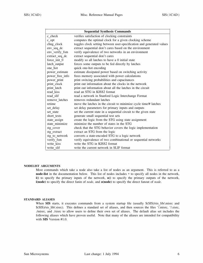
_ __________________________________________________________________________Sequential Synthesis Commands_ __________________________________________________________________________
c_check verifies satisfaction of clocking constraintsc_opt computes the optimal clock for a given clocking schemechng_clock toggles clock setting between user-specification and generated valuesenv_seq_dc extract sequential don’t cares based on the environmentenv_verify_fsm verify equivalence of two networks in an environmentextract_seq_dc extract sequential don’t caresforce_init_0 modify so all latches to have a 0 initial statelatch_output forces some outputs to be fed directly by latchesone_hot quick one-hot encodingpower_estimate estimate dissipated power based on switching activitypower_free_info frees memory associated with power calculationspower_print print switcing probabilities and capacitancesprint_clock print out information about the clocks in the networkprint_latch print out information about all the latches in the circuitread_kiss read an STG in KISS2 formatread_slif read a network in Stanford Logic Interchange Formatremove_latches removes redundant latchesretime move the latches in the circuit to minimize cycle time/# latchesset_delay set delay parameters for primary inputs and outputsset_state set the current state in a sequential circuit to the given stateshort_tests generate small sequential test setsstate_assign create the logic from the STG using state assignmentstate_minimize minimize the number of states in the STGstg_cover check that the STG behavior covers the logic implementationstg_extract extract an STG from the logicstg_to_network converts a state-encoded STG to a logic networkverify_fsm verify equivalence of two combinational or sequential networkswrite_kiss write the STG in KISS2 formatwrite_slif write the current network in SLIF format_ __________________________________________________________________________ ⎜⎜
⎜⎜⎜⎜⎜⎜⎜⎜⎜⎜⎜⎜⎜⎜⎜⎜⎜⎜⎜⎜⎜⎜⎜⎜⎜⎜⎜⎜⎜⎜⎜⎜⎜⎜⎜
⎜⎜⎜⎜⎜⎜⎜⎜⎜⎜⎜⎜⎜⎜⎜⎜⎜⎜⎜⎜⎜⎜⎜⎜⎜⎜⎜⎜⎜⎜⎜⎜⎜⎜⎜⎜⎜
NODELIST ARGUMENTSMost commands which take a node also take a list of nodes as an argument. This is referred to as anode-list in the documentation below. This list of nodes includes ∗ to specify all nodes in the network,i() to specify the primary inputs of the network, o() to specify the primary outputs of the network,i(node) to specify the direct fanin of node, and o(node) to specify the direct fanout of node.
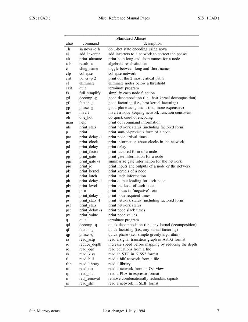
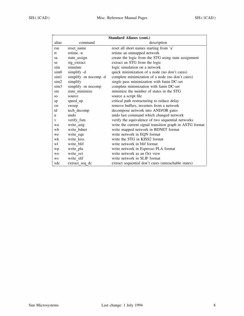
STANDARD ALIASESWhen SIS starts, it executes commands from a system startup file (usually $(SIS)/sis_lib/.misrc and$(SIS)/sis_lib/.sisrc). This defines a standard set of aliases, and then sources the files ˜/.misrc, ˜/.sisrc,./misrc, and ./sisrc to allow users to define their own set of aliases. The default alias set includes thefollowing aliases which have proven useful. Note that many of the aliases are intended for compatibilitywith SIS Version #1.0.
Sun Microsystems Last change: 1 July 1994 6
SIS ( 1CAD ) Misc. Reference Manual Pages SIS ( 1CAD )
_ __________________________________________________________________Standard Aliases
alias command description_ __________________________________________________________________1h sa nova -e h do 1-hot state encoding using novaai add_inverter add inverters to a network to correct the phasesalt print_altname print both long and short names for a nodeasb resub -a algebraic resubstitutionc chng_name toggle between long and short namesclp collapse collapse networkcrit pd -a -p 2 print out the 2 most critical pathsel eliminate eliminate nodes below a thresholdexit quit terminate programfs full_simplify simplify each node functiongd decomp -g good decomposition (i.e., best kernel decomposition)gf factor -g good factoring (i.e., best kernel factoring)gp phase -g good phase assignment (i.e., more expensive)inv invert invert a node keeping network function consistentoh one_hot do quick one-hot encodingman help print out command informationnts print_stats print network status (including factored form)p print print sum-of-products form of a nodepat print_delay -a print node arrival timespc print_clock print information about clocks in the networkpd print_delay print delaypf print_factor print factored form of a nodepg print_gate print gate information for a nodepgc print_gate -s summarize gate information for the networkpio print_io print inputs and outputs of a node or the networkpk print_kernel print kernels of a nodepl print_latch print latch informationplt print_delay -l print output loading for each nodeplv print_level print the level of each nodepn p -n print nodes in ’negative’ formprt print_delay -r print node required timesps print_stats -f print network status (including factored form)psf print_stats print network statuspst print_delay -s print node slack timespv print_value print node valuesq quit terminate programqd decomp -q quick decomposition (i.e., any kernel decomposition)qf factor -g quick factoring (i.e., any kernel factoring)qp phase -q quick phase (i.e., simple greedy algorithm)ra read_astg read a signal transition graph in ASTG formatrd reduce_depth increase speed before mapping by reducing the depthre read_eqn read equations from a filerk read_kiss read an STG in KISS2 formatrl read_blif read a blif network from a filerlib read_library read a libraryro read_oct read a network from an Oct viewrp read_pla read a PLA in espresso formatrr red_removal remove combinationally redundant signalsrs read_slif read a network in SLIF fornat_ __________________________________________________________________ ⎜⎜
⎜⎜⎜⎜⎜⎜⎜⎜⎜⎜⎜⎜⎜⎜⎜⎜⎜⎜⎜⎜⎜⎜⎜⎜⎜⎜⎜⎜⎜⎜⎜⎜⎜⎜⎜⎜⎜⎜⎜⎜⎜⎜⎜⎜⎜⎜⎜⎜⎜⎜⎜⎜⎜⎜⎜⎜⎜⎜⎜⎜
⎜⎜⎜⎜⎜⎜⎜⎜⎜⎜⎜⎜⎜⎜⎜⎜⎜⎜⎜⎜⎜⎜⎜⎜⎜⎜⎜⎜⎜⎜⎜⎜⎜⎜⎜⎜⎜⎜⎜⎜⎜⎜⎜⎜⎜⎜⎜⎜⎜⎜⎜⎜⎜⎜⎜⎜⎜⎜⎜⎜⎜⎜
Sun Microsystems Last change: 1 July 1994 7
SIS ( 1CAD ) Misc. Reference Manual Pages SIS ( 1CAD )
_ _____________________________________________________________________________Standard Aliases (cont.)
alias command description_ _____________________________________________________________________________rsn reset_name reset all short names starting from ’a’rt retime -n retime an unmapped networksa state_assign create the logic from the STG using state assignmentse stg_extract extract an STG from the logicsim simulate logic simulation on a networksim0 simplify -d quick minimization of a node (no don’t cares)sim1 simplify -m nocomp -d complete minimization of a node (no don’t cares)sim2 simplify single pass minimization with fanin DC-setsim3 simplify -m nocomp complete minimization with fanin DC-setsm state_minimize minimize the number of states in the STGso source source a script filesp speed_up critical path restructuring to reduce delaysw sweep remove buffers, inverters from a networktd tech_decomp decompose network into AND/OR gatesu undo undo last command which changed networkv verify_fsm verify the equivalence of two sequential networkswa write_astg write the current signal transition graph in ASTG formatwb write_bdnet write mapped network in BDNET formatwe write_eqn write network in EQN formatwk write_kiss write the STG in KISS2 formatwl write_blif write network in blif formatwp write_pla write network in Espresso PLA formatwo write_oct write network as an Oct viewws write_slif write network in SLIF formatxdc extract_seq_dc extract sequential don’t cares (unreachable states)_ _____________________________________________________________________________ ⎜
⎜⎜⎜⎜⎜⎜⎜⎜⎜⎜⎜⎜⎜⎜⎜⎜⎜⎜⎜⎜⎜⎜⎜⎜⎜⎜⎜⎜⎜⎜⎜⎜
⎜⎜⎜⎜⎜⎜⎜⎜⎜⎜⎜⎜⎜⎜⎜⎜⎜⎜⎜⎜⎜⎜⎜⎜⎜⎜⎜⎜⎜⎜⎜⎜⎜
Sun Microsystems Last change: 1 July 1994 8
SIS ( 1CAD ) Misc. Reference Manual Pages SIS ( 1CAD )
DETAILED COMMAND DESCRIPTIONSact_map [-h heuristic_num] [-n num_iteration] [-f collapse_fanin]
[-g gain_factor] [-d decomp_fanin] [-r filename][-M MAXOPTIMAL] [-qolDsv]
Routine to find an optimal mapping to the Actel architecture. The input is the Boolean network and theoutput is a netlist and the block count (reference: An Architecture for Electrically Configurable GateArrays, Gamal et. al., IEEE J. of Solid State Circuits, April 1989, pp. 394-398).
act_map synthesizes the given circuit onto Actel architecture. It uses a tree-mapping approach to coverthe subject graph with the pattern graphs. The pattern graphs are hard-wired into the code and so nolibrary is to be read in. Subject graph and pattern-graphs are in terms of 2-1 muxes. Subject graph isconstructed for each intermediate node of the network. Either an OBDD (Ordered BDD) and/or a BDDis constructed for each such node. After the entire network is mapped, an iterative_improvement phasemay be entered.
Following options are supported:
-h heuristic_number specifies which one of the two subject_graphs would be constructed.
heuristic num = 1 => OBDD
heuristic num = 2 => BDD (default)
heuristic num = 3 => program decides which one to construct.
heuristic num = 4 => both are constructed and the one with lower mapped cost is selected. Gives thebest result, but typically takes more time.
-M MAXOPTIMAL constructs an optimal OBDD for a node if number of fanins is at most MAXOP-TIMAL.
-n num_iteration specifies the maximum number of iterations to be performed in theiterative_improvement phase. Each such iteration involves a good_decomposition followed by apartial_collapse routine. Partial_collapse tries to collapse each node into its fanouts. Default is -n 0.
-f collapse_fanin considers only those nodes for partial_collapse which have fanin no more thancollapse_fanin. (Default: -f 3).
-g gain_factor makes the program enter the next iteration only if gain in the present iteration is at least(present_cost ∗ gain_factor). (Default: -g 0.01)
-d decomp_fanin considers only those nodes for good_decomposition which have fanin greater than orequal to decomp_fanin. (Default -d 4).
-r filename is the final mapping option. After mapping, a mapped network would be created, in whicheach intermediate node corresponds to one basic block of Actel architecture. A file filename having thenetlist description in a BDNET-like format is also formed. The pin names of the basic block are thesame as those given in a Figure in the paper on Actel architecture (reference: An Architecture for Electr-ically Configurable Gate Arrays, Gamal et al., IEEE J. Solid State Circuits, April 1989, pp. 394-398).
-q makes the program enter a quick_phase routine (after iterative_improvement phase), which greedilyfinds out if it is beneficial to implement the node in negative phase.
-D causes a disjoint decomposition routine to be invoked on the network before mapping starts.
-o causes the OR gate in the basic block to be ignored. So mapping is done onto a three-mux structure.
-v turns on the verbosity flag. When used, information about thealgorithm is printed as it executes.
Sun Microsystems Last change: 1 July 1994 9
SIS ( 1CAD ) Misc. Reference Manual Pages SIS ( 1CAD )
-s gives the statistics, regarding the block count of the circuit.
add_inverter
Add inverters into the network wherever needed to make each signal (including the primary inputs) usedonly in its negative form. After this command, every literal in a node is in the negative form. This isthe appropriate starting point for the technology mapping step.
alias [name [string]]unalias name ...
The alias command, if given no arguments, will print the definition of all current aliases. Given a sin-gle argument, it will print the definition of that alias (if any). Given two arguments, the keyword namebecomes an alias for the command string string, replacing any other alias with the same name. Theunalias command removes the definition of an alias.
It is possible to create aliases that take arguments by using the history substitution mechanism. To pro-tect the history substitution character ‘%’ from immediate expansion, it must be preceded by a ‘\’ whenentering the alias. For example:
sis> alias read read_\%:1 \%:2.\%:1sis> alias write write_\%:1 \%:2.\%:1sis> read blif lionsis> write eqn tiger
will create the two aliases ‘read’ and ‘write’, execute "read_blif lion.blif", and then execute "write_eqntiger.eqn". And...
sis> alias echo2 "echo Hi ; echo \%∗ !"sis> echo2 happy birthday
would print:
Hihappy birthday !
CAVEAT: Currently there is no check to see if there is a circular dependency in the alias definition.e.g.
sis> alias foo "print_stats -f; print_level -l; foo"
creates an alias which refers to itself. Executing the command "foo" will result an infinite loop duringwhich the commands "print_stats -f" and "print_level -l" will be executed.
astg_add_state [-v debug_level] [-m]
Adds state signal transitions to the Signal Transition Graph to guarantee implementability (seeastg_state_min for a recommended script file).
The -m option does not preserve the original ASTG marking, and forces its re-computation (may beslow; dubious usefulness).
astg_contract [-f] <signal-name>
Sun Microsystems Last change: 1 July 1994 10
SIS ( 1CAD ) Misc. Reference Manual Pages SIS ( 1CAD )
Generate the contracted net for the specified signal of the ASTG.
The -f option adds the restriction that the contracted net must also be free-choice. Chu has conjecturedthat this restriction may not be necessary, so it is optional at this time until we have answered this ques-tion.
astg_current
Display information about the current ASTG: its name, whether it is a free-choice net, state machine, ormarked graph, and the number of state machine (SM) and marked graph (MG) components if astg_smcor astg_mgc have been run on the ASTG.
astg_encode [-v debug_level] [-h] [-s] [-u]
Encodes the states of the current State Transition Graph using Tracey’s critical race-free encoding algo-rithm. Used to perform state encoding for asynchronous circuits (see astg_state_min for a recommendedscript file).
The -h option selects a faster heuristic (that may result in more state variables).
The -s option prints out a brief summary of the encoding algorithm results.
The -u option allows to enter user-defined codes (for debugging purposes).
astg_lockgraph [-l]
Build the lock graph for the current ASTG.
With the -l option, edges are added to the ASTG to ensure that the lock graph is connected, and thusthat the ASTG has the Complete State Coding property.
If an ASTG has the CSC property, the state of the circuit can be represented completely by the collec-tion of input, output and internal signals specified in the ASTG. This simplifies many synthesis algo-rithms.
The algorithm works only for ASTGs that are marked graphs (no choice). See astg_state_min for a setof commands that ensure Complete State Coding for more general ASTGs.
astg_marking [-s] [<marking>]
Display or set the initial marking of the ASTG. If no marking is given, the current initial marking isdisplayed. The default format for the marking is the same as for the
The -s option uses a state code format for the marking. This is a list of signal name and value pairs.For example, to set an initial state with signal A at value 0 and B at value 1, use the command:astg_marking -s A 0 B 1
astg_persist [-p]
Add constraints to make an ASTG persistent. With the -p option, non-persistent transitions are printedbut the ASTG is not modified.
For small ASTGs with very high concurrency, enforcing the ASTG persistency property will partiallyand sometimes completely enforce the Complete State Coding property (CSC). If an ASTG has theCSC property, the state of the circuit can be represented completely by the collection of input, outputand internal signals specified in the ASTG. This simplifies many synthesis algorithms.
astg_print_sg
Sun Microsystems Last change: 1 July 1994 11
SIS ( 1CAD ) Misc. Reference Manual Pages SIS ( 1CAD )
Print the state graph of the current ASTG. If no state graph is present, this will create one by tokenflow.
astg_print_stat
Print the statistics of the current ASTG: name of the ASTG file, initial marking, total number of statesin the state graph and the total number of I/O signals.
astg_slow [-v debug_level] [-t tolerance] [-s] [-u] [[-f⎥ -F] external_delay_file] [-d default_external_delay] [-mmin_delay_factor]
Remove hazards from the ASTG implementation, inserting delay buffers after some ASTG signals.Delays are inserted so that no gate within the circuit implementation can react as though the ASTGspecified ordering of signals is reversed in time.
It must be invoked after technology mapping (see astg_to_f for a recommended script file).
The -m option specifies the amount by which all MINIMUM delays are MULTIPLIED (this until thedelay computation will understand min/max delays). Of course 0.0 < min_delay_factor <= 1.0. Defaultvalue: 1.0.
The -t option specifies the tolerance to be used during the hazard check procedure (the larger thespecified value, the more conservative is the algorithm). Default value: 0.0.
The -s option specifies not to use the shortest-path algorithm when computing the delays in the network.This might result in being overly pessimistic (this option is only experimental).
The -f option specifies a file name to search for the minimum delays between output signals and inputsignals of the ASTG (i.e. for those signals that are not being synthesized). This can be useful if someinformation about these signals is known either from the specification or from the synthesis of anothersub-component of the total asynchronous system.
The file can also be updated with the minimum delays between each input signal and each output signalif the -F option is used in place of -f. This allows for separate synthesis of various sub-components ofan asynchronous system. In this case iteration might be necessary to obtain optimal results, and a warn-ing message is issued when the stored information is changed, and a new iteration is required.
The -u option specifies not to remove hazards, but only to update the external elay file (if appropriate).This can be used to remove hazards from a set of Signal Transition Graphs that are synthesizedseparately (e.g. by contraction). In this case, a first round of synthesis can be performed on each SignalTransition Graph, followed by astg_slow with the -F and the -u options, to store the information on thedelay of the function implementing each signal. Then astg_slow can be iterated among the Signal Tran-sition Graphs with the -F option only until convergence is obtained. The results should be comparablewith synthesis and hazard removal from a single Signal Transition Graph, but can be considerably fasterfor large specifications.
The -d option specifies the default minimum delay between output signals and input signals of theASTG (if no information can be obtained from the above described file). The default value is 0.0 (i.e.the environment responds instantaneously), but this can be overly pessimistic, and result in an unneces-sary slow and large implementation.
astg_state_min [-v debug_level] [-p minimized_file] [-c "command"] [-b⎥ -B] [-g⎥ -G] [-u] [-m⎥ -M] [-o #] [-fsignal_cost_file]
Minimizes the current State Transition Graph and derives the information required to encode the associ-ated Signal Transition Graph. The complete sequence of actions to implement a Signal Transition Graphthat does not have Complete State Coding is as follows:
Sun Microsystems Last change: 1 July 1994 12
SIS ( 1CAD ) Misc. Reference Manual Pages SIS ( 1CAD )
astg_to_stg -mastg_state_minastg_encodeastg_add_state
astg_to_f...
The -f option selects a signal cost file. This file should contain one line of the form<signal name> <cost>(e.g. "bus_ack 10") for each signal in the ASTG. The encoding algorithm minimizes the sum of theweights of signals that follow state transitions. Hence this file can be used to strongly favor or disfavorchanging the predecessors of the transitions of a signal.
By default, output signals have a cost of one and input signals have a cost equal to the number of outputsignals plus one. In this way, no input signal is constrained, if possible.
The command may emit a series of diagnostic messages of the form:warning: the STG may not be live (multiple exit point): may need constraint <signal 1> -> <signal 2>These messages may or may not cause a failure (diagnosed as internal error) later on duringastg_add_state. In case of failure, one of the required constraints (ideally the constraint that leastdecreases the circuit performance due to the reduction in concurrency) should be added to the ASTG.The procedure should be repeated until no more such messages occur.
The options listed below are not generally useful except for debugging purposes or to obtain faster (butpotentially less optimal) results for large Signal Transition Graphs. All algorithm speed indicationsreflect average case analysis.
The -B and -b options select Binary Decision Diagrams as internal data structure to find the encodinginformation (both are generally slower than the default selection, but -b is generally faster than -B).
The -M and -m options select Sparse Matrices as internal data structure to find the encoding information(both are generally slower than the default selection, but -m is generally faster than -M). If -M isselected, then -o can be used to define some further internal options (this is strongly discouraged).
The -G and -g options select a greedy (-g) or very greedy (-G) heuristic to find the encoding information(both faster and looser than the default selection).
The -u option selects a generally slower heuristic to find the encoding information.
The -c option allows to use a different minimizer from the default choice. The minimizer must be ableto read and write .kiss format and to write equivalence class information in the output file, in the follow-ing format:#begin_classes <number of classes># <state name> <class number>...
#end_classes
The -p option avoids calling the minimizer altogether, just reading in the specified minimized file (in.kiss format with equivalence class information).
astg_stg_scr [-v debug_level]
Transforms the current State Transition Graph into one that satisfies the Single Cube Restriction.
The Single Cube Restriction means that each state has exactly one associated value of input signalsunder which it is entered. The result is accomplished by state duplication, but the result may be non-minimal. This command is required (and useful) before stg_to_astg.
Sun Microsystems Last change: 1 July 1994 13
SIS ( 1CAD ) Misc. Reference Manual Pages SIS ( 1CAD )
astg_syn [-m] [-r] [-v debug_level] [-x]
Synthesize from the current signal transition graph a two-level implementation which is hazard-freeunder the unbounded gate delay model (i.e., gates have unbounded delays, wires have zero delays).
The synthesis is performed in two steps. The first step derives a state graph from the ASTG by per-forming a reachability analysis. If no initial marking is given, then astg_syn will try to find a live, safeinitial marking. The second step uses the state graph generated in step one to perform hazard analysisand synthesis. All static hazards and critical races are removed. astg_syn tries to remove all dynamichazards arising from multiple input or output changes. When it cannot remove such hazards, it willprint the terms which can potentially produce hazards and the conditions under which hazards can beproduced. From this user can remove the dynamic hazards by removing some concurrency. The result-ing implementation may be neither prime nor irredundant.
The following options are not intended for general use.
The -m does not perform cube reduction and always returns a prime cover implementation free of statichazards. As a consequence, dynamic hazards due to multiple input/output changes may not be removed.
The -r option runs ESPRESSO in single-output mode. The implementation will be prime and irredun-dant, but may have static hazards and dynamic hazards.
The -v option specifies the debug level.
The -x assumes that a state graph has already been derived, and perform synthesis directly from thegiven state graph. State graph can be derived by using _astg_flow.
astg_to_f [-v debug_level] [-r] [-s signal_name] [-d]
Generate an initial two-level implementation of each output signal specified by the current Signal Transi-tion Graph.
If the initial marking is not defined, then a valid marking is searched for. The list of potential hazards,used by astg_slow, is also produced.
One primary input is generated for each signal (both input and output) specified by the ASTG, with thesame name as the signal (and "_" appended if the signal is an output).
One primary output is generated for each output signal specified by the ASTG, with the same name asthe signal. The primary output is driven directly by the primary input.
One asynchronous latch is generated for each output signal specified by the ASTG, connecting the com-binational logic function implementing the signal (a "fake" primary output with the same name as thesignal and "_next" appended) and the corresponding primary input.
If some signal is not used inside the combinational logic, then the corresponding primary input and latchis not created (unless the option -r is specified).
The -s option adds a set of fake primary outputs that ensure that the named signal is implemented as aSet-Reset flip-flop. If, in addition, the -d option is specified, the functions for the Set and Reset input aremade disjoint. This may increase the implementation cost, but reduces its sensitivity to dynamic hazards.
An error message results if either no valid marking is found (in which case it might be advisable todefine it in the ASTG specification file) or the ASTG does not have the Compatible State Coding pro-perty (i.e. if two markings with different sets of enabled output signals have the same binary label). Seeastg_state_min for a recommended action in the latter case.
A typical ASTG synthesis and optimization script should look like:astg_to_f
gkx -abresub -ad; sweepgcx -b
Sun Microsystems Last change: 1 July 1994 14
SIS ( 1CAD ) Misc. Reference Manual Pages SIS ( 1CAD )
resub -ad; sweepeliminate 0decomp -g ∗eliminate -1
mapastg_slow
astg_to_stg [-v debug_level] [-m]
Generate a State Transition Graph from the current Signal Transition Graph. The State Transition Graphhas one input signal for each signal in the Signal Transition Graph (both input and output), and one out-put signal for each output signal in the Signal Transition Graph.
If the initial marking is not defined, then a valid marking is searched for.
An error message results if no valid marking is found (in which case it might be advisable to define it inthe ASTG specification file).
The -m option additionally performs a pre-minimization step that produces a State Transition Graph suit-able for subsequent state encoding commands (such as, e.g., astg_state_min).
atpg [-fFhrRpt] [-d RTG_depth] [-n n_fault_sim] [-v verbosity_level][-y random_prop_depth] file
Perform test generation for both combinational and sequential circuits using random test generation,deterministic test generation, and fault simulation. Deterministic test generation is accomplished by oneof two methods. The first method is a three-step test generation algorithm consisting of combinationaltest generation (assuming that latch outputs are controllable, and that latch inputs are observable), fol-lowed by state justification and propagation, when necessary. The combinational test generation isaccomplished using Boolean satisfiability. Justification and propagation are performed using implicitstate transition graph traversal techniques. If the three-step method does not generate a test for a fault,then the product of the good and faulty circuit is built and traversed, as in sequential circuit verification.If this traversal proves the circuits equivalent, then the fault is redundant; otherwise any differentiatingsequence is a test for the fault.
Fault collapsing is performed before test generation, across only simple gates. Both fault equivalenceand fault dominance are used to reduce the fault list.
For combinational circuits, external don’t cares are automatically taken into account when the don’t carenetwork is attached to the care network. The PI’s and PO’s of the external don’t care network (when itis not NIL) must match exactly with the care network. That is, the don’t care network cannot specifyonly a subset of the PI’s or PO’s of the care network. If this condition is not met, then the atpg packageautomatically adds dummy primary inputs and outputs to the external don’t care network.
Reverse fault simulation is performed as a post-processing step to reduce test set size.
The -f option causes the atpg not to perform fault simulation of deterministically-generated tests onuntested faults.
The -F option causes the atpg not to use reverse fault simulation.
The -h option restricts the boolean satisfiability algorithm to not use non-local implications. Four greedyordering heuristics are tried in this case instead of the default of eight. Hard-to-test faults that can onlybe tested with non-local implication information are aborted by this option.
The -r option causes the atpg not to perform random test pattern generation.
The -R option causes the atpg not to perform random propagation. (Deterministic propagation is stillattempted).
Sun Microsystems Last change: 1 July 1994 15
SIS ( 1CAD ) Misc. Reference Manual Pages SIS ( 1CAD )
The -p option causes the atpg not to build any product machines. Thus, neither deterministic propagationnor good/faulty product machine traversal will be performed.
The -t option first converts the network to arbitrary fanin AND and OR gates. The decomposed networkis returned.
The -d option allows the specification of the length of the random sequences applied during random testgeneration. The default length is the depth of the circuit’s state transition graph.
The -n option allows the specification of the number of sequences to fault simulate at one time duringfault simulation. The default is the system word length.
The -v allows the specification of the verbosity level of the output.
The -y option allows the specification of the length of the random sequences applied during random pro-pagation. The default length is 20.
If file is specified, test patterns are written out to the given file.
Note: in order to use this command with sequential circuits, the circuit reset state must be specified inthe circuit input file.
bdsyn
A special command exported for use by bdsyn(1). Not for general use.
buffer_opt [-l #] [-f #] [-c] [-d] [-T] [-L] [-v #] [-D] node-list
Builds fanout trees for the nodes in the node-list. If no nodes are specified selects the nodes to be buf-fered in order to improve performance of the entire network. The network is assumed to be mapped.
The -l # option specifies the number of fanouts which a node can have so as to be eligible for buffering.The default is 2, hence any multi-fanout node is a candidate for buffering.
The -f # option specifies the transformations to use. Set the three least significant bits indicate the use(value == 1) of the transformations. xx1 to use the repower transformation, x1x to use an unbalancedtransformation and 1xx to use the balanced distribution of signals. More than one transformation can beset active. Thus to allow the algorithm full flexibility use the value = 7 (111 in binary notation) which isalso the default.
The -c option specifies that one pass be carried out. The default is to iterate till no improvement isachieved.
The -d option allows the complex gates to be decomposed into smaller ones so as to increase drivecapability. By default the complex gates are retained.
The -L option traverses the network from outputs to inputs ensuring that for every node, the gate thatimplements it does not drive a load greater than the max_load limit specified for that gate. THISOPTION IS NOT YET IMPLEMENTED.
The -T option displays the circuit performance as the iterations progress. If the required times at the out-puts are not specified the circuit delay is shown, else the minimum slack value is displayed.
The -v #,-D option are for debugging. The -v # option is the most verbose and the amount of verbositycan be increased by letting the argument for -v range from 1 to 100.
c_check -[nd] -[SH]#.#
Verifies that the given circuit satisfies the constraints for correct clocking. By default the circuit isassumed to be mapped to a library. Use the -n option to use the unit-fanout delay model.
Sun Microsystems Last change: 1 July 1994 16
SIS ( 1CAD ) Misc. Reference Manual Pages SIS ( 1CAD )
The user can give global set-up (and hold) times for all memory elements using the -S (-H) option. Bydefault it computes the set-up and hold times from the library. If the optimal clocking scheme was foundusing the c_opt command make sure you use the same delay model!
The -d value selects the debug level. The range is 1-5.
c_opt -[nGI] -[dSHmM]#.#
Computes the optimal clock for a given clocking scheme. Finds rise and fall times for the clock events.A single clock multi-phase clocking scheme is assumed.
The algorithm works on mapped and unmapped networks (default is mapped). Note that to ensure everynode is mapped, you should read in the blif file, read in the library, map the circuit and then run theoptimal clocking algorithm. It is a known fact that reading in a mapped netlist often causes some nodesto remain un-mapped. The command will abort in such a case. The -n option is used for the unit-fanoutdelay model.
By default the algorithm uses a special Linear program solver based on the Floyd-Warshall algorithm.An alternate formulation using binary search is available (-B) as long as no minimum duty cycle con-straints are imposed.
The -I option is used for 2 phase inverted clocking schemes only.
The user can give global set-up (and hold) times for all memory elements using the -S (-H) option. Bydefault it computes the set-up and hold times from the library.
The -m option permits the user to specify a minimum phase separation as a fraction of the clock cycle.Similarly the -M option sets the maximum phase separation as a fraction of the clock cycle.
The -d value selects the debug level (range 0-4).
This routine runs faster (upto 2X) when compiled with the priority queue library from octtools (use flag-DOCT when compiling this directory).
chng_clock
Toggles the setting of the clock between the user-specified clock settings (specified in the blif file) andthe working values (generated by algorithms inside SIS).
All algorithms use the current setting as input. If the algorithms modify the clocking scheme or thecycle-time they write the modified clocking scheme into the working fields. Thus, to write out the bliffile containing the clock scheme generated by algorithms inside SIS, the setting must first be set to theworking one and then write_blif must be invoked.
chng_name
Toggles the network between long-name mode (user supplied names) and short-name mode (automati-cally generated single-character names).
collapse [n1] [n2]
Collapse nodes in the network. With no arguments, the entire network is collapsed into a single-level offunctions (i.e., two-level form). Each output will be expressed in terms of the primary inputs.
Given a single node, that function is collapsed until it is represented entirely in terms of primary inputs.
Sun Microsystems Last change: 1 July 1994 17
SIS ( 1CAD ) Misc. Reference Manual Pages SIS ( 1CAD )
Given two arguments, it is assumed that the second node is a fanin of the first node. In this case, thisdependency is removed (the first node is expressed without the second node as a fanin).
Please note that this command negates any mapping that may have been done at an earlier time.
Caution should be taken when collapsing network to two levels because the two level representationmay be too large. The alternative is to use eliminate (selective collapse). Refer to eliminate for thedetails.
constraints [node_1....node_n]
Print the values of the various delay constraints for the nodes in the argument list, which must be eitherinputs or outputs. Also prints the default values of the default delay parameters for the network. Usedto check the values set by set_delay.
decomp [-gqd] [node-list]
Decompose all the nodes in the node-list. If the node-list is not specified, all the nodes in the currentnetwork will be decomposed. Decompostion will factor nodes and make the divisor a new node withinthe network, re-expressing other nodes in terms of this newly introduced node. It is one of thetransforms used to break down large functions into smaller pieces, usually at the cost of introducing afew more literals.
If the -q option (the default) is specified, the quick decomp algorithm is used which extracts out an arbi-trary kernel successively. Because of the fast algorithm for generating an arbitrary kernel, decomp -q isvery fast compared with the decomp -g. In most cases, the result is very close. This command isrecommended at the early phase of the optimization.
If the -g option is specified, the good decomp algorithm is used which successively extracts out the bestkernel until the function is factor free, and applies the same algorithm to all the kernels just extracted.This operation will give the best algebraic decomposition for the nodes. But, since it generates all thekernels at each step, it takes more CPU time. In general, decomp -q should be used in the early stageof the optimization. Only at the end of the optimization, should decomp -g be used.
If the -d option is specified, the disjoint decomposition is performed. Currently, the disjoint decomposi-tion is limited to the following simple algorithm: It partitions the cubes into sets of cubes having dis-joint variable support, creates one node for each partition, and a node (the root of the decomposition)which is the OR of all the partitions.
echo args ...
Echoes the arguments to standard output.
eliminate [-l limit] thresh
Eliminate all the nodes in the network whose value is less than or equal to thresh. The value of a noderepresents the number of literals saved in the literal count for the network by leaving the node in thenetwork. If the value is less than (or equal to) the threshold, the node will be eliminated by collapsingthe node into each of its fanouts. A primary input or a primary output will not be eliminated.
The value of the node is approximated based on the number of times the node is used in the factoredform for each of its fanouts. Note that if a node is used only once, its value is always -1.
limit is used to control the maximum number of cubes in any node. The default is 1000. Using a verylarge limit may result in collapsing the network to two levels. In general, if the circuit is collapsible,the command collapse is more efficient.
Sun Microsystems Last change: 1 July 1994 18
SIS ( 1CAD ) Misc. Reference Manual Pages SIS ( 1CAD )
env_seq_dc [-v n] filename.blif
This command extracts sequential don’t cares based on unreachable states. It builds the product of thecurrent network with the network passed as argument, computes the set of reachable states of the pro-duct, extracts from that the set of reachable states of the original network, and uses its complement tobuild a don’t care network for the current network. Any previous don’t care network is discarded.
full_simplify or equiv_nets should be run afterwards to exploit these don’t cares.
External inputs of the current network are connected to matching external outputs of the network passedas argument and vice-versa. Nodes match if and only if they have the same name.
-v allows the specification of the verbosity level of the output. The default value is 0.
The method used to compute the set of reachable states is the product method. See extract_seq_dc fordetails.
env_verify_fsm [-v n] [-V] fsm.blif env.blif
Verify the equivalence of two synchronous networks in a given environment. The current network iscompared with fsm.blif under the environment defined by the env.blif network. The environment is asequential circuit that generates the inputs of the circuits under verification, and possibly takes someinputs from them. What is verified is that the current network and the fsm.blif network are substituablefor one another when used in the context of the env.blif network.
The input and output variables from the three networks are matched by names. It is assumed that all thelatches in both designs are clocked by a single, global clock. The verification is done by implicitlyenumerating all the states in the product machine, and checking that the outputs are equivalent for allreachable state pairs starting from the initial state of the product machine.
-v allows specification of the verbosity level of the output.
By default, the command returns an error status if the verification fails. When option -V is used, itreturns an error status if the verification succeeds.
equiv_nets [-v n]
This command simplifies the network using net equivalence. With full_simplify, it is one of the tworoutines able to take advantage of network don’t cares.
equiv_nets groups all nets of the network by equivalence classes. Two nets are equivalent if and only ifthey always compute the same function with respect to the external care set. It only uses input don’tcares, not observabiilty don’t cares.
For each equivalence class, equiv_nets selects a lowest cost net, and moves the fanout of all the othernets of the equivalence class onto the lowest cost net.
Finally, it calls the command sweep.
-v allows the specification of the verbosity level of the output. The default value is 0.
espresso
Collapse the network into a PLA, minimize it using espresso, and put the result back into the multiple-level nor-nor form.
extract_seq_dc [-o depth] [-v n] [-m method]
Extract sequential don’t cares based on unreachable states. The unreachable states are computed byimplicitly enumerating the set of reachable states in the circuit starting from an initial state and thencomputing the inverse of that set. full_simplify or equiv_nets should be run afterwards to exploit these
Sun Microsystems Last change: 1 July 1994 19
SIS ( 1CAD ) Misc. Reference Manual Pages SIS ( 1CAD )
don’t cares.
-o depth allows the specification of the depth of search for good variable ordering. A larger value fordepth will require more CPU time but determine a better ordering. The default value is 2.
-v allows specification of the verbosity level of the output.
The -m option specifies method for determining the reachable states. consistency builds the entire tran-sition relation and uses it to determine the reached states. bull does output cofactoring to find the reach-able states. The product method is similar to the consistency method but input variables are smoothedas soon as possible as the characteristic function is being built. This makes the size of the resultingBDD representing the characteristic function of the transition relation smaller. The default method isproduct.
factor [-gq] node-list
Throw away the old factored forms and factor each node in the node-list, and store the factored formswith the nodes. If the -q option is specified, the quick factor algorithm is used to factor the node. If the-g option is specified, the good factor algorithm is used to factor the node.
fanout_alg [-v] alg_list
Activates selectively one or more fanout algorithms. For a list of fanout algorithms known to the system,use the -v option. The algorithms activated are the ones specified in the list. One algorithm, noalg, isalways active. two_level is a fast, area efficient algorithm. The best results are obtained with two_level,bottom_up, lt_trees, and mixed_lt_trees.
Fanout optimization itself is performed using the map command.
fanout_param [-v] fanout_alg [property value]
Changes the default parameter values associated with specific fanout algorithms. For a list of theseparameters and their values, use the -v option with a fanout algorithm.
force_init_0
This command replaces all latches initialized to 1 by latches initialized to 0. It inserts an inverter beforeand after the latch to maintain circuit behavior.
This command is useful for certain types of FPGA architectures which do not support the initializationof latches to 1.
free_dc
Frees the don’t care network associated with a network. This command is used for debugging andexperimental purposes.
full_simplify [-d][-o ordering] [-m method] [-l] [-v verbose]
Simplify each node in the network using the local don’t cares generated in terms of fanins of each node.First compatible observability plus external don’t cares are generated for each node in terms of primaryinputs. Then the image computation techniques are used to map these don’t cares to the local space ofeach node. This technique removes most redundancies in the network. The satisfiability don’t cares fora subset of the nodes in the network which have the same support as the node being simplified is alsogenerated. An ordering is given to the nodes of the network and local don’t cares for the nodes arecomputed according to that ordering. Each node is simplified using its local don’t cares and anappropriate satisfiability don’t care subset.
Sun Microsystems Last change: 1 July 1994 20

SIS ( 1CAD ) Misc. Reference Manual Pages SIS ( 1CAD )
-d If this option is used no observability don’t cares are computed. In this case the local don’t cares areonly the unreachable points in the local space of each node (a subset of the satisfiability don’t care set).
-o Used for BDD ordering. If 0 (default) is used, variables are ordered based on their depth. If 1 is used,the level of a node is used for its ordering.
method specifies the algorithm used to minimize the nodes. snocomp (default) invokes a single passminimization procedure that does not compute the complete offset. nocomp invokes the full minimiza-tion procedure (ala ESPRESSO) but does not compute the complete offset. dcsimp invokes single passtautology-based minimizer.
-l generates fanin don’t cares only for nodes with the same or subset support as the node being minim-ized which have level less than the node being minimized. The level is the largest number of nodes onthe longest path from the node to a primary input.
-v prints out extra info for debugging the code.
SIS(1) UNIX Programmer’s Manual SIS(1)
fx [-o] [-b limit] [-l] [-z]
Greedy concurrent algorithm for finding the best double cube divisors and single cube divisors. Findsall the double cube and single cube divisors of the nodes in the network. It associates a cost function toeach node, and extracts the node with the best cost function greedily.
The -o option only looks for 0-level two-cube divisors.
The -b option reads an upper bound for the number of divisors generated. The default value is 50000.This is because the number of divisors in some cases can grow very large.
The -l option changes the level of each node in the network as allowed by the slack between therequired time and arrival time at that node.
The -z option uses zero-weight divisors (in addition to divisors with a larger weight). This means thatdivisors that contribute zero gain to the overall decomposition are extracted. This may result in anoverall better decomposition, but take an exhorbitant amount of time.
gcx [-bcdf] [-t threshold]
Extract common cubes from a network, re-express the network in terms of these cubes, and in the pro-cess cut down on the number of literals needed in the network.
The -b option chooses the best cube at each step when examining possible cubes to be extracted; other-wise, the more efficient ping-pong algorithm is used to find a good (but not necessarily the best) cube ateach step.
The -c option uses the complement of each cube as well as the cube when dividing the new cube intothe network.
The -f option uses the number of literals in the factored form for the network as a cost function fordetermining the best cube to be extracted.
The -t option sets a threshold such that only a cube with a value greater than the threshold will beextracted. By default, the threshold is 0, so that all possible cube divisors are extracted.
Sun Microsystems Last change: 1 July 1994 21
SIS ( 1CAD ) Misc. Reference Manual Pages SIS ( 1CAD )
The -d option enables a debugging mode which traces the execution of gcx.
gkx [-1abcdfo] [-t threshold]
Extract multiple-cube common divisors from the network.
The -a option generates all kernels of all function in the network when building the kernel-intersectiontable. By default, only level-0 kernels are used.
The -b option chooses the best kernel intersection as the new factor at each step of the algorithm; this isdone by enumerating and considering each possible kernel intersection, and choosing the best. Bydefault, the more efficient ping-pong algorithm is used to find a good (but not necessarily the best) ker-nel intersection.
The -c option uses the new factor and its complement when attempting to introduce the new factor intothe network.
The -d option enables debugging information which traces the execution of the kernel extract algorithm.
The -f option uses the number of literals in the factored form for the network as the cost function whendetermining the value of a kernel intersection; by default, the number of literals in the sum-of-productsform for the network is used.
The -o option allows for overlapping factors.
The -t option sets a threshold such that divisors are extracted only while their value exceeds the thres-hold. By default, the threshold is 0 so that all possible multiple-cube divisors are extracted from thenetwork.
The -1 option performs only a single pass over the network. By default, the kernel extract algorithm isiterated while there are still divisors whose value exceeds the given threshold.
help [-a] [command]
Given no arguments, help prints a list of all commands known to the command interpreter. The -aoption provides a list of all debugging commands, which by convention begin with an underscore. If acommand name is given, detailed information for that command will be provided.
history [-h] [num]
Lists previous commands and their event numbers. The -h option suppresses printing the event number.If num is specified, lists the last num events. Lists the last 30 events if num is not specified.
History Substitution:
The history substitution mechanism is a simpler version of the csh history substitution mechanism. Itenables you to reuse words from previously typed commands.
The default history substitution character is the ‘%’ (‘!’ is default for shell escapes, and ‘#’ marks thebeginning of a comment). This can be changed using the "set" command. In this description ’%’ is usedas the history_char. The ‘%’ can appear anywhere in a line. A line containing a history substitution isechoed to the screen after the substitution takes place. ‘%’ can be preceded by a ‘\’ in order to escapethe substitution, for example, to enter a ‘%’ into an alias or to set the prompt.
Each valid line typed at the prompt is saved. If the history variable is set (see help page for set), eachline is also echoed to the history file. You can use the "history" command to list the previously typedcommands.
Substitutions: at any point in a line these history substitutions are available
Sun Microsystems Last change: 1 July 1994 22
SIS ( 1CAD ) Misc. Reference Manual Pages SIS ( 1CAD )
%:0 Initial word of last command.%:n n’th argument of last command.%$ Last argument of last command.%∗ All but initial word of last command.
%% Last command.%stuf Last command beginning with "stuf".%n Repeat the n’th command.%-n Repeat the n’th previous command.ˆoldˆnew Replace "old" w/ "new" in previous command.
Trailing spaces are significant during substitution.Initial spaces are not significant.
invert node-list
Invert each node in the node-list. It is used when the complement of a node is to be implemented.Note that it does not change the logic function of the current Boolean network, but will have an effecton the structure of the network.
invert_io node-list
This command reverses the polarity of the specified nodes. The nodes have to be external primaryinputs or external primary outputs.
The polarity inversion is done by adding an inverter before a primary output or after a primary input.
ite_map [-n num_iter] [-C cost_limit] [-f collapse_fanin][-m map_method] [-d decomp_fanin] [-M MAXOPTIMAL] [-clorsvD]
Routine to find an optimal mapping to Actel’s ACT1 architecture. The input is the Boolean networkand the output is a netlist and the block count (reference: An Architecture for Electrically ConfigurableGate Arrays, Gamal et. al., IEEE J. of Solid State Circuits, April 1989, pp. 394-398).
ite_map synthesizes the given circuit onto Actel ACT1 architecture. The pattern graphs are hard-wiredinto the code and so no library is to be read in. Each intermediate node of the network is checked to seeif it matches onto one ACT1 module. This check is done using a Boolean matching algorithm. If not,then a subject graph is constructed for the node function. The subject graph (as well as the pattern-graphs) is in terms of 2-1 muxes: it uses ITEs (if-then-else DAGs) and ROBDDs (Reduced OrderedBDDs) for the mapping. After an initial mapping of the network, an iterative_improvement phase maybe entered. Local collapse and decomposition operations are performed for better quality.
Following options are supported:
-m map_method specifies which one of the two subject_graphs would be constructed.
map_method = 1 => Standard mapping for each node.
map_method = 2 => construct a sub-network from each node. Map the sub-network using iterativeimprovement and finally replace the node with the mapped sub-network.
-n num_iteration specifies the maximum number of iterations to be performed in theiterative_improvement phase. Default is -n 0.
-F collapse_fanins_of_fanout used in partial collapse. Collapses a node into fanouts only if after col-lapsing, each fanout has at most collapse_fanins_of_fanout fanins (Default: -F 15).
Sun Microsystems Last change: 1 July 1994 23
SIS ( 1CAD ) Misc. Reference Manual Pages SIS ( 1CAD )
-C cost_limit in partial collapse, collapse a node only if its cost is at most cost_limit (Default: -C 3).
-f collapse_fanin considers only those nodes for partial collapse which have at most collapse_faninfanins (Default: -f 3).
-d decomp_fanin considers only those nodes for decomposition in iterative improvement which havefanin greater than or equal to decomp_fanin. (Default -d 4).
-M MAXOPTIMAL constructs an optimal ROBDD (if the ROBDD option is selected) for a node ifnumber of fanins is at most MAXOPTIMAL.
-r is the final mapping option. After initial mapping and possible iterative improvement, a mapped net-work is created in which each intermediate node corresponds to one ACT1 module. If not specified, thenetwork may not have a one-to-one correspondence with the ACT1 module.
-D selects the decomposition method. If specified, computes a factored form of the node and then con-structs ITE for each factor.
-c causes the matching algorithm to be exact. If not specified, matching is approximate.
-o causes the OR gate in ACT1 to be ignored. So mapping is done onto a three-mux structure.
-v turns on the verbosity flag. When used, information about thealgorithm is printed as it executes.
-s gives the statistics, regarding the block count of the circuit.
latch_output [-v n] node-list
The nodes passed as argument should be external primary outputs. This command forces the listedexternal primary outputs to be fed by a latch. This is accomplished by moving latches forward by retim-ing.
The command fails if there is a combinational dependency between an external primary input and one ofthe specified primary outputs.
This function is useful to guarantee that certain outputs will not glitch. It is handy if that output is tocontrol an external device such as the write enable signal of a memory chip.
-v allows the specification of the verbosity level of the output. The default value is 0.
map [-b #][-f #][-i][-m #][-n #][-r][-s][-p][-v #] [-A][-B #][-F][-G][-W]
Perform a technology mapping on the current network. A library must be read using the read_librarycommand before mapping can be performed. The result of the mapping may become invalidated if acommand such as plot or print_stats -f is executed which computes a factored form representation ofevery node.
To produce a minimum area circuit with no consideration for load limits, the recommended option ismap -m 0.
To produce a minimum area circuit that respects load limits, the recommended option is map -m 0 -AF.Use _check_load_limit command to check for load limit violations.
To produce a minimum delay circuit that respects load limits, the recommended option is map -n 1-AFG. To specify required times in order to allow the mapper to trade off delay and area, use theset_delay command.
Details about the meanings of the various options follow.
The -b n sets the number by which the load value should be multiplied in case of a load limit violationduring fanout optimization.
Sun Microsystems Last change: 1 July 1994 24
SIS ( 1CAD ) Misc. Reference Manual Pages SIS ( 1CAD )
The -f n option controls the internal fanout handling. A value of ’0’ disables it completely (i.e. the map-ping is strictly tree-based). A value of ’1’ enables an heuristics approximating the cost of the previoustree at fanout branches. A value of ’2’ enables the usage of cells with internal fanout (such as EXORand MULTIPLEXER). A value of ’3’ (default) enables both. None of these values is guaranteed to givethe best solution in all cases, but ’3’ usually does. A warning is issued if the current value can give badresults with the current network (use undo before mapping again).
The -i option disables the inverter-at-branch-point heuristic. It is intended for experimentation with dif-ferent mapping heuristics.
The -m option controls the cost function used for a simple version of the tree covering algorithm. Amode of ’0’ (the default) minimizes the area of the resulting circuit. A mode of ’1’ minimizes the delayof the resulting circuit (without regard to the total area). An intermediate value uses as cost function alinear combination of the two, and can be used to explore the area-delay tradeoff. A value of ’2’minimizes the delay on an estimate of the critical path obtained from a trivial 2-input NAND mapping,and the area elsewhere.
The -n option allows the access to a better tree covering algorithm. It can only be used in delay mode,i.e. with an argument of 1: -n 1. This algorithm gives better performance than -m 1 but is noticeablyslower. It uses a finer dynamic programming algorithm that takes output load values into account, while-m 1 option supposes all loads to be the same. As a consequence, the -n 1 option performs better than-m 1 especially with rich libraries of gates. Both algorithms use heuristics to guess the load value atmultiple fanout points. Both options should always be used with fanout optimization turned on.
If -r is given (raw mode), the network must already be either 1- and 2-input NAND gates, or 1- and 2-input NOR gates form, depending on whether a NAND-library, or a NOR-library was specified when thelibrary was originally read (see read_library). If -r is not given, appropriate commands are inserted totransform the network into the correct format.
The -s option prints brief statistics on the mapping results.
The -p option forces the mapper to ignore the delay information provided by the user at primary inputsand primary outputs (arrival times, required times, loads, drive capability). It is intended for experimen-tal use. This option forces the arrival times and required times to be all 0, the loads and drive capabili-ties to be all equal to the load and drive capability of the second smallest inverter in the library. If thereis only one inverter, the data are taken from that inverter.
The -v n options is for development use, and provides debugging information of varying degrees of ver-bosity as the mapping proceeds.
The -A option recovers area after fanout optimization at little or no delay cost by resizing buffers andinverters.
The -B n option controls the enforcement of load limits during fanout optimization. A value of 0ignores the load limits. A value of 1 takes load limits into account. The default is set to 1. Thisoption is effective only in conjunction with fanout optimization. It is implemented by artificiallyincreasing the load at a gate output by a multiplicative factor whenever the load exceeds the limitspecified in the library. The default multiplicative factor is 1000. This value can be changed with the -bn option. There is a priori no reason to change this value.
The -F option performs fanout optimization. This disables the internal fanout handling (i.e. forces -f 0).In order to recover area after fanout optimization use the -A option. There are several fanout optimiza-tion algorithms implemented in SIS. For details, type help fanout_alg and help fanout_params.
The -G option recovers area after fanout optimization at no cost in delay by resizing all gates in the net-work.
The -W option suppresses the warning messages.
Sun Microsystems Last change: 1 July 1994 25
SIS ( 1CAD ) Misc. Reference Manual Pages SIS ( 1CAD )
one_hot
Does a quick one-hot encoding of the current STG. It assigns one-hot codes, minimizes the resultingPLA using espresso, and returns the network to SIS.
phase [-qgst] [-r n]
Decide for each node whether to implement the node or its complement in order to reduce the total costof the network. If the network is mapped, the cost is the total area and the network will be keptmapped, otherwise, the cost is the total number of inverters in the network assuming all the inverters arealready in the network. At the end, all the necessary inverters are inserted into the network and all theextra inverters are removed from the network.
The default algorithm, which can also be specified by -q option, is a greedy algorithm called quickphase. The -g option uses the Kernighan-Lin type algorithm called good phase. The -s option choosesthe Simulated Annealing algorithm. The -r n option chooses a random-greedy algorithm which does arandom assignment first, uses a greedy approach to get to a local minimum, and iterates n times. If the-t option is specified, some tracing information is printed as the assignment proceeds.
plot_blif [-k] [-r] [-i] [-g WxH+X+Y] [-n name]
The plot_blif command creates a window with an abstract representation of the network, at its currentlevel of optimization, labeling all nodes, including primary inputs and outputs. Vectors are used toshow relationships between the various nodes. Latches are not printed explicitly. The network is drawnas an acyclic combinational circuit. Labelled arrows indicate the locations of the latches.
The -k option "kills" (closes) the most recent plot window with the current network name.
The -r option replaces the contents of an existing plot window with the current network structure. Thisis useful if the network has been modified since it was last plotted. If no plot window is open with thecurrent network name, the command has no effect.
The -i option forces a plot of the internal network structure used by SIS. The default is to plot the struc-ture corresponding to the write_blif command. The primary difference in the internal structure is in howprimary outputs are handled.
The -g option allows an initial geometry to be specified for the plot window.
The -n option allows "name" to be used for the plot window name instead of the network name.
power_estimate [-m c] [-d c] [-t c] [-s c] [-a n] [-e f] [-n n][-f file] [-S] [-M n] [-N n] [-R] [-h] [-v]
Estimates the power dissipated in a circuit due to switching activity:P = 0.5 x Vddˆ2 x sum(p x C ) / f
i i iwhere
Vdd = 5Vf = 20MHzp = expected number of transitions of node i in one clock cyclei
C = capacitive load of node ii
The expected number of transitions of each node per clock cycle is calculated through symbolic simula-tion, based on the static probabilities of the primary inputs (by default prob_one = prob_zero = 0.5). The
Sun Microsystems Last change: 1 July 1994 26
SIS ( 1CAD ) Misc. Reference Manual Pages SIS ( 1CAD )
capacitive load of a node is obtained by summing the gate capacitances of its fanout nodes and addingsome internal drain capacitance. Gate capacitances are multiple of a minimum sized transistor (0.01pF),admitting transistor sizing based on the number of inputs to the node (up to a value max_input_sizing,default 4). Drain capacitances are calculated from the number of transistors this node has (multiple of0.005pF) and this number can be obtained either from a factored form or sum of products.
-m c Estimation mode, c either SAMPLING or BDD (default).
-d c Delay model, c one of ZERO (default), UNIT or GENERAL (from library).
-t c Estimation type, c one of COMBINATIONAL (default), SEQUENTIAL, PIPELINE or DYNAMIC(for dynamic domino circuits).
-s c PS lines probability calculation method, c one of APPROXIMATE (default), EXACT or UNIFORM(0.5 is used). Only used for SEQUENTIAL type.
-a n Number of PS lines to be correlated (default 1). Only used for the APPROXIMATION method.
-e f Maximum error allowed for PS lines probabilities (default 0.01). Only used for the APPROXIMA-TION method.
-n n Number of sets of 32 input vectors to be simulated (default 100). Only used for SAMPLING mode.
-f filename Allows the specification of input probabilities, node capacitances and node delays in the for-mat:
name "nodename" p0 "value"name "nodename" p1 "value"name "nodename" cap_factor "value"name "nodename" delay "value"
-S Assumes complex gates in sum of products form (default is factored form).
-M n Maximum number of inputs of a node considered for transistor sizing (default 4).
-N n Interval of input vectors for which the current value of power estimation is printed. Only used forSAMPLING mode.
-R Sets latch capacitances to 0, only comb power reported.
-h Prints power_estimate usage.
-V n Verbose run time information.
Note: currently a memory fault occurs on the RS6000 when the exact calculation is used for presentstate probabilities. This is probably due to the use of stg_extract.
Sun Microsystems Last change: 1 July 1994 27
SIS ( 1CAD ) Misc. Reference Manual Pages SIS ( 1CAD )
power_free_info
Frees data structures storing capacitance and switching of every node in the network.
power_print
Prints the switching probability and capacitance for each node in the network. Only valid after a powerestimation has been performed.
print [-n] [-d] node-list
Print all the nodes in the node-list in sum-of-product form.
If -n option is specified, the nodes are printed in the negative form. (i.e. a’ + b’ will be printed as (a +b)’).
If -d option is specified, the nodes in the external don’t care network are printed.
print_altname node-list
Print the alternate name of all the nodes in the node-list. If the current name mode is short (SIS inter-nal name), the alternate name will be the long name (user-specified name) and vice-versa.
print_clock
Prints the clocking scheme associated with the current network. The clocking scheme printed dependson the current setting of the clock data structure (see chng_clock).
print_delay [-alrs] [-m model] [-p n] [-f file-name] [node-list]
Do a delay trace (static timing analysis) on the network depending on the specified model and print thedelay data. Without any arguments the routine will use the library model which assumes that the net-work is mapped and will print the arrival times, required times and the slack for all the nodes in the net-work.
Specifying an optional node-list will print the delay data only for the specified nodes.
The user can selectively have portions of the delay data printed. The option -a will cause the arrivaltimes to be printed. The option -r will cause the required times to be printed. The option -s will causethe slacks at nodes to be reported. The option -l will cause the load driven by the node to be printed.
The option -p n when specified with one of the options -[alrs] will print out the delay data so that thefirst n nodes with the most critical values are printed. The critical portion of the delay data is determinedby the first of the options -[alrs] specified. Thus specifying -p n -[al] prints the n nodes with thegreatest arrival-time/load. For the -[rs] option the nodes with the smallest required-time/slack areprinted.
The delay model can be specified by the -m option followed by one of the following keywords --- unit,unit-fanout, library, mapped or tdc. Specifying unit results in delay being computed as 1 unit per nodein the network. unit-fanout adds an additional delay of 0.2 per fanout. If a library has been read inusing the read_library command one can use more accurate models, mapped and library, by using datastored in the library. Using the model library assumes that the network has been mapped. The mappedmodel does not make this assumption and will do a mapping of the nodes on an individual basis to com-pute a delay model for use during the delay trace. The tdc model is an attempt to predict the delay of a
Sun Microsystems Last change: 1 July 1994 28
SIS ( 1CAD ) Misc. Reference Manual Pages SIS ( 1CAD )
node based on the distribution of arrival times. The parameters used in this model prediction are option-ally specified using the -f option.
print_factor node-list
Print all the nodes in the node-list in the factored form. If a node has not beed factored, factor -q willbe used to factor the node.
print_gate [-ps] node-list
Prints the information provided in the library for the list of mapped gates.
The -p option prints the pin information of the gates.
The -s option prints summary of the gates and their area.
print_io [-d] [node-list]
Print both fanin and fanout list for each node in the node-list. Absence of node-list implies all thenodes in the current network.
If the -d option is specified, the nodes in the external don’t care network are considered.
print_kernel [-as] node-list
Print kernels and corresponding co-kernels of all the nodes in the node-list. If -a option (default) isspecified, all kernels, including the function itself if it is a kernel, are printed. If -s option is specified,only the sub-kernels are printed.
print_latch [-s] [node-list]
With no arguments, print_latch prints out information for all the latches in the network. The informa-tion printed for each latch is the latch input, latch output, initial value, current value, synchronizationtype, and controlling node. The latch values can be 0, 1, 2 (don’t care), and 3 (undefined).
If the -s option is specified, only the latch input, output, initial and current values are given. If a node-list is given, only the latches associated with those nodes are printed (each node should be a latch inputor output).
print_level [-l] [-c] [-m model] [-t value] [node-list]
Prints the nodes of the network according to their level. When called with a node-list, only the nodes inthe transitve fanin of the specified nodes are printed. The primary inputs are assigned level 0, and thelevel of a node is the length of the longest path from it to a primary input. The -l options prints onlythe number of levels in the network.
If the -c option is specified, only critical nodes are printed according to their level. The delay trace isdone according to the -m model option (default is the unit-fanout model) and all the nodes with a slackwithin a -t value of the smallest slack are considered to be critical.
print_library [-a][-f][-h][-l][-r] [function-string]
Print the contents of the current library. If the optional string is given, only the combinational gateswith the same logic function as the string will be printed. function-string is in the format of read_eqn.For example
print_library "f=!(a∗b);"will print all combinational gates with a NAND2 logic function.
Sun Microsystems Last change: 1 July 1994 29
SIS ( 1CAD ) Misc. Reference Manual Pages SIS ( 1CAD )
The -a option prints asynchronous type latches matching the ’function-string’.
The -f option prints falling edge triggered flip-flops matching the ’function-string’.
The -h option prints active high transparent latches matching the ’function-string’.
The -l option prints active low transparent latches matching the ’function-string’.
The -r option prints rising edge triggered flip-flops matching the ’function-string’.
print_map_stats
Prints delay and area information of the network. The network should be mapped.
print_state
Prints out the current state of the machine for both the STG and the logic implementation. For the logicimplementation, the current state is printed as a string of integers representing the values on the latches:0, 1, 2 (don’t care), and 3 (undefined). For the STG, the current state is printed with its symbolic andencoded names.
print_stats [-f] [-d]
Print the current network status, which includes the network name, number of primary inputs (pi),number of primary outputs (po), number of nodes (nodes), the number of latches (latches), the numberof literals in the sum-of-product form (lits(sop)), and the number of states in the STG (#states(STG)).
If -f option is specified, the number of literals in the factored form (lits(fac)) is computed. This could beslow when the factored form for some network takes too long to generate.
If -d option is specified, the statistics of the external don’t care network is printed.
print_value [-a] [-d] [-p n] node-list
Print the value of all the nodes in the node-list. The value is currently defined as the number of literalsincreased if the node were eliminated from the network. Since the value of a node depends on the par-ticular factored form of the node and its fanouts, all the nodes which don’t have factored forms will befactored using factor -q.
The -a option prints the values in ascending order.
The -d option prints the values in descending order.
The -p takes an argument n, and directs print_value to only print the top n values.
quit [-s]
Stop the program. Does not save the current network before exiting. -s frees all the memory beforequitting. This is slower, and is used for finding core leaks or when sis is called from another program.
read_astg [<file-name>]
Read a text description of an Asynchronous Signal Transition Graph (ASTG). The overall format fol-lows the style of BLIF, and uses an adjacency list to describe the net interconnection structure. If nofilename is specified, the description is read from stdin.
All names in the ASTG description must start with a letter, consist of letters, digits and underscores, andare case-sensitive. A signal transition is represented with a suffix: "+" means a low to high transition,"-" means high to low, "˜" means toggles (changes to the opposite value.
Sun Microsystems Last change: 1 July 1994 30
SIS ( 1CAD ) Misc. Reference Manual Pages SIS ( 1CAD )
.model <model-name>This gives an arbitrary name to the ASTG, and it must be the first line of the model description.
.inputs <signal-list>Specifies a list of names of ASTG input signals. Signals from multiple .inputs are concatenated.
.outputs <signal-list>Specifies a list of names of ASTG output signals. Signals from multiple .inputs are concatenated.
.internal <signal-list>Specifies a list of names of ASTG internal signals, i.e. signals which are only used to maintain stateinformation.
.dummy <name-list>Specifies a list of names which are accepted as dummy or null transitions. Null transitions are necessaryto specify some behaviors using the ASTG syntax. By convention, the name "e" is used as a dummysignal (to represent epsilon transitions)..graph
Indicates the lines which follow describe the ASTG net structure using an adjacency list format. Thismust follow all signal declarations (.inputs, etc.). Net places are optional for simple constraints betweentwo transitions; in this case an intervening place is generated automatically. Multiple instances of atransition are distinguished by following them with a slash and a copy number. For example, a secondinstance of transition "t+" can be specified by "t+/2". Copy numbers do not have to be consecutive.
.marking {<place-list>} An initial marking can optionally be specified after the net structure has beengiven. Implied places (see .graph) between two transitions x∗ and y∗ can be specified using the syntax<x∗,y∗>..end This required line indicates the end of the ASTG description.
Error messages are printed for any unrecognized input sequences.
read_blif [-a] filename
Read in a network from the file filename which is assumed to be in blif format. The network name isgiven by the .model statement in the file. If a .model is not given, the network name is the filenamewith any trailing extension removed. See the blif.tex document for a complete description of the blifformat.
The user can also specify an external don’t care network. This network must be placed after the carenetwork in the same file. The statement .exdc must precede the description of the external don’t care net-work. The names of primary outputs and primary inputs of the external don’t care network must beexactly the same as the names of primary outputs and primary inputs of the care network.
Usual filename conventions apply: - (or no filename) stands for standard input, and tilde-expansion isperformed on the filename.
Normal operation is to replace the current network with a new network. If no external don’t care net-work is specified, the external don’t care network is set to NIL (nonexistent). Otherwise the externaldon’t care network is replaced by the new external don’t care network. The -a option specifies that thenew network should be appended to the current network. Functions are associated between the two net-works using the long names of each network. Name conflicts (where two functions attempt to define thesame name) generate warning messages and are resolved by renaming the signal from the new network.
The -s option, though accepted, has no effect on read_blif, and is instead reserved for the read_placommand.
read_eqn [-a] [filename]
Sun Microsystems Last change: 1 July 1994 31
SIS ( 1CAD ) Misc. Reference Manual Pages SIS ( 1CAD )
Read a set of logic equations in the format expected by eqntott(1). Each equation becomes a node inthe logic network.
INORDER and OUTORDER can be used to specify the primary inputs and primary outputs for the net-work. If neither is given, then primary inputs are inferred from signals which are not driven, and pri-mary outputs are inferred from signals which do not have any fanout.
The equations are of the form "<signal> = <expr> ;". For reference, the equation format uses the opera-tors:
_ ______________________() grouping!= (or ˆ) exclusive-or== exclusive-nor! complement& (or ∗) boolean-and⎥ (or +) boolean-or_ ______________________ ⎜⎜
⎜⎜⎜⎜⎜⎜
⎜⎜⎜⎜⎜⎜⎜⎜
As a simple extension to eqntott, juxtaposition of two operands stands for boolean-and, and ’ used as apost-fix operator stands for complement. Hence,
F = a∗!b + c∗!d ;and
F = a b’ + c d’ ;represent the same equation.
Note that eqntott and read_eqn treat the intermediate nodes of a network slightly differently. read_eqnwill not make an intermediate node a primary output unless it also appears in the OUTORDER list.Also, the resulting network is a multiple-level network with all of the intermediate signals preserved.Finally, eqntott is order-dependent in that it requires signals to be defined before they can be used again;read_eqn relaxes this condition.
The -a option specifies that the new network should be appended to the current network. Functions areassociated between the two networks using the long names of each network. Name conflicts (where twofunctions attempt to define the same name) generate warning messages and are resolved by renaming thesignal from the new network.
The -s option, though accepted, has no effect on read_eqn and is instead reserved for the read_placommand. Note that since the characters ’(’ and ’)’ are used for grouping, they cannot be part of a sig-nal name.
read_kiss [filename]
Reads a kiss2 format file into a state transition graph. The state names may be symbolic or strings of"0" and "1". Inputs and outputs should be strings of "0", "1", and "-"; inputs should not be symbolic.The kiss2 format is described in doc/blif.tex. Note that there is no mechanism for specifying the namesof the I/O pins in kiss2. Naming can be done in SIS by specifying a blif file containing the .inputs and.outputs lines (which give I/O names) followed by the embedded kiss2 file. See also stg_to_network,read_kiss_net.
Note that read_kiss followed by write_kiss alters the ordering of the product terms. This could make adifference in the nova output.
read_library [-ainr] filename
Read a SIS-format library for future technology mapping. The -a option appends the library to thecurrent library; otherwise, any previous library is discarded. The -i flag suppresses adding extra invert-ers to all of the primitives. This is intended for debugging only. The -n flag requests that a library, if itis generated, be made using NAND gates rather than NOR gates. The -r flag reads a raw library format(given in BLIF) rather than the normal genlib format.
Sun Microsystems Last change: 1 July 1994 32
SIS ( 1CAD ) Misc. Reference Manual Pages SIS ( 1CAD )
read_oct cell[:view]
Read in a network from the Oct facet ‘cell:view:contents’. If ‘view’ is not specified, it defaults to‘logic’. The network name is set to ‘cell:view’. Oct nets without names are given machine-generatedunique names. All primary inputs and outputs are named the same as the equivalent Oct formal termi-nals of the facet.
This operation replaces the current network with the new network.
read_pla [-a] [-s] [-c] filename
Read in an espresso-format PLA from the file filename (see espresso(5) for more information). The net-work name is derived from the filename with any trailing extension removed.
Usual filename conventions apply: - (or no filename) stands for standard input, and tilde-expansion isperformed on the filename.
Normal operation is to replace the current network with a single-level network of complex gates with thesame logic functions as the PLA outputs. This makes each PLA output a separate single-output functionand is a good starting point for the standard scripts. If don’t care conditions exist, the external don’tcare network is also replaced with a single-level network which implements the don’t care conditions ofthe PLA. Otherwise, the external don’t care network is set to NIL (nonexistent).
The -c option replaces the current network with a two-level network of NOR-gates (and inverters) whichimplements the PLA. This preserves the multiple-output nature of the PLA. The external don’t carenetwork is manipulated exactly the same as above. This used to be the default, while the -s optionreplaced the network with a single-level network as described above. The -s option has been retainedfor compatibility.
The -a option specifies that the new network should be appended to the current network. Functions areassociated between the two networks using the long names of each network. Name conflicts (two func-tions attempt to define the same name) generate warning messages and are resolved by renaming the sig-nal from the new network.
read_slif filename
Read in a network from the file filename which is in slif format. SLIF is a hierarchical circuit descrip-tion language and the root network, the one returned to the caller, is defined to be the first networkencountered in the file filename.
red_removal [-hqrRpt] [-d RTG_depth] [-n n_fault_sim] [-v verbosity_level][-y random_prop_depth]
Perform sequential redundancy removal using random test generation, deterministic test generation, andfault simulation. Deterministic test generation is accomplished by one of two methods. The first methodis a three-step test generation algorithm consisting of combinational test generation (assuming that latchoutputs are controllable, and that latch inputs are observable), followed by state justification and propa-gation, when necessary. The combinational test generation is accomplished using Boolean satisfiability.Justification and propagation are performed using implicit state transition graph traversal techniques. Ifthe three-step method does not generate a test for a fault, then the product of the good and faulty circuitis built and traversed, as in sequential circuit verification. If this traversal proves the circuits equivalent,then the fault is redundant; otherwise any differentiating sequence is a test for the fault.
Each time a redundant fault is encountered during deterministic test generation, the redundant line isreplaced by a constant 1 or 0, and deterministic test generation begins again. At the end of the redun-dancy removal procedure, the network is 100% testable for single stuck faults unless the test generatoraborts on some faults.
Sun Microsystems Last change: 1 July 1994 33
SIS ( 1CAD ) Misc. Reference Manual Pages SIS ( 1CAD )
For combinational circuits, external don’t cares are automatically taken into account when the don’t carenetwork is attached to the care network. The PI’s and PO’s of the external don’t care network (when itis not NIL) must match exactly with the care network. That is, the don’t care network cannot specifyonly a subset of the PI’s or PO’s of the care network. If this condition is not met, then the atpg packageautomatically adds dummy primary inputs and outputs to the external don’t care network.
The -h option restricts the boolean satisfiability algorithm to not use non-local implications. Four greedyordering heuristics are tried in this case instead of the default of eight. Hard-to-test faults that can onlybe tested with non-local implication information are aborted by this option.
The -q specifies "quick redundancy removal." With this option, the deterministic test generation algo-rithm identifies only those redundant faults that cannot be excited from any reachable state. In practice,quick redundancy removal usually gives the same results as regular redundancy removal, in much lesstime.
The -r option causes the test generator not to perform random test pattern generation.
The -R option causes the test generator not to perform random propagation. (Deterministic propagationis still attempted).
The -p option causes the test generator not to build any product machines. Thus, neither deterministicpropagation nor good/faulty product machine traversal will be performed.
The -t option first converts the network to arbitrary fanin AND and OR gates. The decomposed networkis returned.
The -d option allows the specification of the length of the random sequences applied during random testgeneration. The default length is the depth of the circuit’s state transition graph.
The -n option allows the specification of the number of sequences to fault simulate at one time duringfault simulation. The default is the system word length.
The -v allows the specification of the verbosity level of the output.
The -y option allows the specification of the length of the random sequences applied during random pro-pagation. The default length is 20.
Note: in order to use this command with sequential circuits, the circuit reset state must be specified inthe circuit input file.
reduce_depth [-b] [-d #] [-g] [-r] [-s #] [-v #] [-R #.#] [-S #] [-f #]
This command is to be used to improve the speed of a network before technology mapping. It performsa partial collapse of the network by first clustering nodes according to some criteria and collapsing eachcluster into a single node. The clusters are formed as follows: a maximum cluster size is first computed,and the algorithm finds a clustering that respects this size limit and minimizes the number of levels inthe network after the collapsing of the clusters. The size limit is a limit on the number of nodes coveredby the cluster, and does not take into account the complexity of the nodes. Therefore this commandshould only be used on networks decomposed into simple gates. The cluster size limit can be providedin a variety of ways, depending on which option is used.
The -b option performs the clustering under the duplication ratio constraint specified by -R option.
The -d # option specifies the desired depth of the network after clustering. The depth counts the numberof nodes. Since each node is expressed as a sum-of-products, specifying depth of 1 corresponds to col-lapsing the network to two levels of logic. The algorithm computes the minimum cluster size limit thatyields a depth of n.
The -g option prints out statistics based on cluster sizes. No clustering is done.
The -r option specifies a modification of the clustering algorithm that produces the same number oflogic levels but with less duplication of logic.
Sun Microsystems Last change: 1 July 1994 34
SIS ( 1CAD ) Misc. Reference Manual Pages SIS ( 1CAD )
The -s # option specifies the desired cluster size limit.
The -v # option specifies a verbosity level. It is used mainly for debugging.
The -R #.# option specifies the maximum duplication ratio. The default is 2.0.
The -S # option specifies the smallest cluster size limit that produces the same depth as a cluster sizelimit of n.
The -f # option specifies a cluster size limit in terms of the number of fanins of the cluster. Its intendeduse is for table-lookup FPGAs. It is a poor man’s version of FlowMap.
remove_dep [-o] [-v n] input output-list
The first node passed as argument should be an external primary input. The remaining nodes passed asarguments should be external primary outputs. This command assumes that the dependency between thegiven input and the given outputs is structural but not logical, and it removes these structural dependen-cies by forcing the input at 0 in the cone of logic going from the input to the listed outputs.
The logic that depends on the given input and is shared with outputs not passed as arguments is dupli-cated.
This function is useful when performing hierarchical optimization, to guarantee that sis does not intro-duce dependencies that will create combinational logic loops when the hierarchy is reassembled.
-v allows the specification of the verbosity level of the output. The default value is 0.
With option -o the constant 1 is used instead of the constant 0 to replace the input.
remove_latches [-v n] [-f n] [-r] [-b]
This command removes redundant latches, using three different techniques.
First, it performs some local retiming, by moving forward latches across combinational logic if thatdecreases the latch count. This optimization can be disabled by specifying the option -r.
Second, it looks for boot latches, that is latches fed by a constant but initialized at the opposite value. Ifthere are such latches, it looks for a state equivalent to the initial state in which the initial value of thelatch is equal to the value of its constant input. When this optimization applies, the latch can beremoved, and constant folding propagates the constant across the logic. This optimization can be dis-abled by specifying the option -b.
Third, it computes the set of reachable states, and checks whether some latches cannot be deduced com-binationally from other latches. If that is the case, and if the fanin limit specified by the -f option is notexceeded, the latch is removed and replaced by combinational logic.
-v allows the specification of the verbosity level of the output. The default value is 0.
replace [-t n] [-v n]
This is a simple routine that performs the same function as resub -a -d on a network decomposed in 2-input NAND gates using tech_decomp -o 2. It is just much faster.
The -v n specifies the verbosity level. It is only used for debugging.
reset_name [-ls]
Resets either the short names (starting again from the single letter a) with the -l option, or the SIS-generated long-names (starting again from [0]) with the -s option.
Sun Microsystems Last change: 1 July 1994 35
SIS ( 1CAD ) Misc. Reference Manual Pages SIS ( 1CAD )
resub [-a] [-b] [-d] [node-list]
Resubstitute each node in the node-list into all the nodes in the network. The resubstitution will try touse both the positive and negative phase of the node. If node-list is not specified, the resubstitution willbe done for every node in the network and this operation will keep looping until no more changes of thenetwork can be made. Note the difference between resub ∗ and resub. The former will apply theresubstitution to each node only once.
The -a (default) option uses algebraic division when substituting one node into another. The division isperformed on both the divisor and its complement.
The -b option uses Boolean division when substituting one node into another. NOTE: Boolean resubsti-tution has not yet been implemented.
The -d option directs resub not to use the complement of a given node in algebraic resubstitutions.
retime [-nfim] [-c #.#] [-t #.#] [-d #.#] [-a #.#] [-v #]
Applies the retiming transformation on the circuit in an effort to reduce the cycle time. The retimingoperation is supported only for single phase, edge-triggered designs. Both mapped and unmapped net-works can be retimed. The algorithm attempts to maintain the initial state information.
The algorithm expects to work on mapped networks so that accurate delays on the gates can be used.However, an unmapped network can be retimed by using the -n option. In that case the delay througheach node is computed according to the unit-fanout delay model. The user should be aware of the factthat when retiming circuits containing complex registers (JK, D-flip flops with enables/presets), the com-plex registers may have to be decomposed into simpler gates.
By default the algorithm uses a relaxation based approach which is very fast. An alternate formulationuses a mathematical programming formulation and can be selected using the -f option. After profilingon a number of circuits only one will be retained.
The -m option can be used to minimize the number of registers under cycle time constraints. If the cycletime is not specified using the -c option then this command will try to minimize the cycle time. Thus toobtain the absolute minimum number of registers for a circuit the user should specify a very loose cycletime constraint (very large value for the -c option).
The retiming algorithm will try to compute the new initial states of the latches. In case no feasible ini-tial state exists the retiming is aborted and the network is not modified. To suppress the initializationroutine use the -i option. In that case the initial values for all the latches after retiming is set to value of2 (DONT_CARE).
The desired clock period can be specified with the -c value option. When this option is not used thealgorithm first checks to see if there is a cycle_time specification with the current network (the valuedepends on the current setting of the clock_flag in the network) and tries to meet this. If no cycle_timeis specified with the design the retiming operation tries to minimize the cycle time. For this it uses abinary search for testing feasible clock values. The tolerance of the binary search can be specified withthe -t value option (the default is 0.1).
Latches in the network can be assigned a propogation delay and an area. These are helpful in the realis-tic modelling of the circuit delay and area. Use the -d value option to specify the delay through a latch(to approximate the setup and propogation delay of the latch) and the -a value option to specify the areaof a latch. In case of mapped networks, these values are automatically determined from the library ofgates.
The -v value selects the verbosity level. The range is 1-100 (100 will literally swamp you with a lot ofunneeded data). Use the value 1 to see the progress of the algorithm.
Sun Microsystems Last change: 1 July 1994 36
SIS ( 1CAD ) Misc. Reference Manual Pages SIS ( 1CAD )
save filename
Save a copy of the current executable to a file which can be restarted. This can be used to freeze thecurrent network or the current library for later optimization. When the executable filename is executed,execution returns to the top-level of the command interpreter.
NOTE: The save command is very operating-system dependent and may not be implemented on yoursystem. If this is the case then the save command is unusable on your system.
set [name] [value]unset name ...
A variable environment is maintained by the command interpreter. The set command sets a variable toa particular value, and the unset command removes the definition of a variable. If set is given no argu-ments, it prints the definition of all variables.
Different commands use environment information for different purposes. The command interpretermakes use of the following:
autoexecDefines a command string to be automatically executed after every command processed by thecommand interpreter. This is useful for things like timing commands, or tracing the progressof optimization.
sisout Standard output (normally stdout) can be re-directed to a file by setting the variable sisout.
siserr Standard error (normally stderr) can be re-directed to a file by setting the variable siserr.
history Each valid command entered at the prompt can be echoed to a file by setting the variable his-tory.
history_charBy default the character ‘%’ is used to do the history substitution inside sis. This can bechanged by setting the variable history_char.
shell_charBy default the character ‘!’ is used to do invoke shell commands from inside sis. This can bechanged by setting the variable shell_char.In order to switch the interpretation of shell_char and history_char it is neccessary to first set
history_char and then the shell_char. Alternately, you may escape the current history char bypreceeding it with a ‘´ while setting the shell_char. In addition none of them can be set to a‘#’ which is reserved for comments.
filec Setting this variable enables the user to use "file-completion" like in the C-shell. An ESCcauses the current line to be extended to its unique completion. A CTRL-d generates a list ofthe possible extensions.
open_pathopen_path (in analogy to the shell-variable PATH) is a list of colon-separated strings givingdirectories to be searched whenever a file is opened for read. Typically the current directory(.) is first in this list. The standard system library (typically $SIS/sis_lib) is always implicitlyappended to the current path. This provides a convenient short-hand mechanism for reachingstandard library files.
prompt defines the prompt string. If the prompt string contains a ‘%’(or whatever the history_char hasbeen set to using the set command), the ‘%’ will be replaced whenever the prompt is printedby the current event number.
set_delay [-a⎥d⎥ i⎥ l⎥r f] [-A f] [-D f] [-I f] [-L f] [-R f] [-S f] [-W f][o1 o2 ... ⎥ i1 i2 ...]
Sun Microsystems Last change: 1 July 1994 37
SIS ( 1CAD ) Misc. Reference Manual Pages SIS ( 1CAD )
Set various delay parameters for the inputs and outputs of a network. These timing constraints are usedby the print_delay command in addition to commands like speed_up, buffer_opt, and map that per-form delay optimizations. The values for these constraints are numbers and it is the user’s responsibilityto ensure that these values are meaningful when a particular delay model is used during the optimiza-tions. Capitalized options set defaults, lower-case options set the parameters for the nodes in nodelist,which is either a list of output nodes or a list of input nodes.
The option -A sets the default arrival time for primary inputs to the real value f. The option -R sets thedefault required time for primary outputs to f. The -D option sets the default drive on a primary inputto f, and the -L option sets the default load on primary outputs to f. The -I option specifies the defaultvalue for the maximum load that can be present at a primary input. The -S option sets the wire load perfanout to f. The wire loads for a given number of fanouts can be specified with the -W option. With theith use of the -W option, the load for a gate driving i outputs is set to the value f.
The settings can be undone by using a negative number for the value. This will result in the parameterto be "unspecified" and the individual commands will use appropriate defaults if neccessary.
The -a, -r, -d, -i, and -l options can be used to specify the delay constraints on specific nodes (asopposed to the uppercase options which specify a default value for ALL terminals). These terminal-specific values will supersede the defaults specified with the uppercase options. The -a (-r) option setsthe arrival (required) time to f for the specified nodes if the node list given is a list of primary inputs(outputs). The -d (-i) option sets the drive (maximum load limit) for each node in the list to f; if thereis a non-primary input in the list this is an error. The -l option sets the load on each node in the list tof; if there is a non-primary output in the list this is an error.
set_state [-s] [-i] [name]
Sets the current state in the machine to the given state. If no state is given, it sets the current state tothe initial state (resets the machine). If the -s option is given, only the state of the STG is changed; ifthe -i option is specified, only the state of the logic implementation is changed. If no logic implementa-tion exists, or if only the state of the STG is to be changed, then the state name should be symbolic;otherwise it should be the encoded name of the state.
short_tests [-fFhirtV] [-v verbosity_level] file
Perform test generation for sequential circuits with the goal of producing small test sets. Random testgeneration is not used unless its use is specified by the user. Deterministic test generation is accom-plished by one of two methods. The first method is a three-step test generation algorithm consisting ofcombinational test generation (assuming that latch outputs are controllable, and that latch inputs areobservable), followed by state justification and propagation, when necessary. The combinational test gen-eration is accomplished using Boolean satisfiability. Justification and propagation are performed usingimplicit state transition graph traversal techniques. If the three-step method does not generate a test for afault, then the product of the good and faulty circuit is built and traversed, as in sequential circuitverification. If this traversal proves the circuits equivalent, then the fault is redundant; otherwise any dif-ferentiating sequence is a test for the fault. Fault simulation is performed after each deterministic testgeneration.
Fault collapsing is performed before test generation, across only simple gates. Both fault equivalenceand fault dominance are used to reduce the fault list.
Deterministically-generated tests may start from the circuit reset state or a state reached by the applica-tion of another test. In the latter case, the new test is appended onto the end of the old test.
Reverse fault simulation is performed as a post-processing step to reduce test set size.
The -f option causes the test generator not to perform fault simulation of deterministically-generatedtests on untested faults.
Sun Microsystems Last change: 1 July 1994 38
SIS ( 1CAD ) Misc. Reference Manual Pages SIS ( 1CAD )
The -F option causes the test generator not to use reverse fault simulation.
The -h option restricts the boolean satisfiability algorithm to not use non-local implications. Four greedyordering heuristics are tried in this case instead of the default of eight. Hard-to-test faults that can onlybe tested with non-local implication information are aborted by this option.
The -i option causes the test generator not to append new tests onto the end of old tests.
The -r option causes the test generator to perform random test pattern generation and random propaga-tion.
The -t option first converts the network to arbitrary fanin AND and OR gates. The decomposed networkis returned.
The -v allows the specification of the verbosity level of the output.
The -V causes the test generator to not use the three-step algorithm to generate tests. Instead, onlygood/faulty product machine verification is used to generate tests, thus guaranteeing that each individualtest generated is the shortest possible.
If file is specified, test patterns are written out to the given file.
Note: in order to use this command with sequential circuits, the circuit reset state must be specified inthe circuit input file.
sim_verify [-n # pats] filename.blif
Verify that two networks are equivalent using random-pattern simulation. That is, generate a randominput vector, simulate the logic network, and check that the outputs between the two networks agree.The first network is the current network, and a second network is read from the file filename.blif: itmust be a blif format file. (This restriction will be fixed when the command interpreter is expanded tohandle multiple networks.)
-n gives the number of random patterns to simulate.
NOTE: this command only works for combinational networks.
simplify [-d][-i <num>[:<num>]] [-m method] [-f filter] [node-list]
Simplify each node in the node-list using method with the don’t-care set generated according to dctype.
method specifies the algorithm used to minimize the nodes. snocomp (default) invokes a single passminimization procedure that does not compute the complete offset. nocomp invokes the full minimiza-tion procedure (ala ESPRESSO) but does not compute the complete offset. dcsimp invokes single passtautology-based minimizer.
dctype specifies how the don’t-care set is generated. The default don’t care set generated is a subset ofthe fanin don’t care set. -d option specifies that no don’t care set is used. -i m:n specifies that the fanindon’t cares of nodes within m levels of transitive fanin and n levels of transitive fanout of these transi-tive fanin are to be generated.
filter specifies how the don’t-care set is filtered. exact (default) uses the exact filter. disj_sup uses thedisjoint support filter.
Note that a node function is replaced with the simplified version if the new function has fewer literals infactored form. In the case of a tie, the node function is replaced if the new function has fewer literals insum-of-products form.
simulate in1 in2 in3 ...
For the current implementation of the network, given a value (’0’ or ’1’) for each of the primary inputsof the network, simulate prints the value produced at each of the primary outputs. The correspondence
Sun Microsystems Last change: 1 July 1994 39
SIS ( 1CAD ) Misc. Reference Manual Pages SIS ( 1CAD )
of the input values and the primary inputs can be determined by the order in which the primary inputsand outputs are printed using the write_eqn command.
For example, for a three-input AND gate, the command
simulate 1 1 0
will produce a
0
NOTE: For sequential circuits, this command essentially assumes that all latches are clocked simultane-ously by a single clock. Simulation will take the current values on the latches (which can be displayedby using print_latch) and the user-supplied primary input values and simulate the network, placing thenew latch values in the current state of the latches. The values of the outputs and the new state areprinted. If a more sophisticated simulation method is needed, timing simulation should be used; this isnot currently implemented in SIS.
source [-psx] filename
Read commands from a file. The -p option prints a prompt before reading each command, and the -xoption echoes each command before it is executed. The -s option silently ignores an attempt to executecommands from a nonexistent file.
Arguments on the command line after the filename are remembered but not evaluated. Commands inthe script file can then refer to these arguments using the history substitution mechanism.
EXAMPLE:
Contents of test.scr:
read_blif %:2collapsewrite_eqn %:2.eqn
Typing "source test.scr lion.blif" on the command line will execute the sequence
read_blif lion.blifcollapsewrite_eqn lion.blif.eqn
If you type "alias st source test.scr" and then type "st lion.blif bozo", you will execute
read_blif bozocollapsewrite_eqn bozo.eqn
because "bozo" was the second argument on the last command line typed. In other words,command substitution in a script file depends on how the script file was invoked.
Some standard script files are provided. script (executed by typing source script is a script that workswell on most examples. script.boolean uses a larger part of the don’t care set during two-level minimi-zation, requiring more time and producing better results. script.algebraic uses a smaller part of thedon’t care set. script.rugged uses the newest BDD-based techniques, and script.delay synthesizes a cir-cuit for a final implementation that is optimal with respect to speed.
Sun Microsystems Last change: 1 July 1994 40
SIS ( 1CAD ) Misc. Reference Manual Pages SIS ( 1CAD )
speed_up [-m model] [-d #] [-w #] [-t #.#] [-i] [-c] [-T] [-a #] [-vD] node-list
Speed-up the nodes in the node-list. If no nodes are specified, it selects the nodes to be speeded-up inorder to speed-up the entire network. The best decomposition seen so far is accepted (except with the -cflag). The network after running speed_up is composed of 2-input AND gates and inverters.
The -m model option selects the delay model according to which the delay data is computed. The valuesallowed for model are unit, unit-fanout and mapped. The unit delay model counts the level of the cir-cuit as its delay. The unit-fanout model is intended to capture a technology-independent model and itassigns a delay of 1 unit to each gate and 0.2 units to each fanout stem. The mapped delay model usesthe delay data in the library to compute delay.
The -d # option selects the distance up to which the critical fanins are collapsed in order to do thespeed-up. A fast value is 3, a good one is 6.
The -t #.# option determines which nodes are considered critical. The critical nodes are those with aslack within #.# of the most negative slack.
The -w # option selects between the area mode and the pure timing mode. A value of 0 selects pure-timing mode while a value of 1 will conserve as much area as possible.
The -i option specifies that only the initial 2-input NAND decomposition be carried out.
The -c option specifies that one pass be carried out. The new decomposition is always accepted, even ifit results in a slower circuit.
The -T option displays the delay as the iterations progress.
The -a # option tries to do the specified number of attempts when restructuring a node. By default thealgorithm tries only one attempt at the restructuring. This option is for experimental use at this stage.
The -v and -D options display debugging information.
speedup_alg [-v] alg_list
Activates selectively one or more performance enhancing algorithms. For a list of local optimizationsknown to the system, use the -v option. The algorithms activated are the ones specified in the list. Formapped circuits the algorithms perform the optimization and remap the sub-network that was optimized.noalg performs no optimization, it only remaps the region. fanout builds a fanout-tree while repowersimply uses a gate of greater drive Of the others divisor and 2c_kernel perform restructuring by extract-ing kernels and 2-cube divisors. When applied to the complement of the function these are calledcomp_div and comp_2c respectively. Techniques based on the existing structure are cofactor which per-forms timing-driven-cofactoring and bypass applies the generalized-bypass transformation.
Performance optimization itself is performed using the speed_up command without the -f option.
state_assign progname options
Perform state assignment on the current STG. The program used for state assignment is progname andit is given the options options. The program progname must exist somewhere in the user’s path.
The state assignment program is given the current STG, and returns a logic implementation. After exe-cution of the state_assign command, both the STG and the logic implementation are available foroptimization.
The state assignment program called must conform to the specification (see doc/SPEC). Currently, theprograms that are compatible with this specification and are shipped with SIS are nova and jedi. To gethelp information for a specific program, use the -h option (i.e. state_assign nova -h would produce helpinformation for the nova state assignment program).
Sun Microsystems Last change: 1 July 1994 41
SIS ( 1CAD ) Misc. Reference Manual Pages SIS ( 1CAD )
A one-hot encoding can be obtained by using state_assign progname -e h. Note that nova and jediproduce different results for one-hot encoding. jedi produces typical one-hot codes (1000) while novaproduces one-hot codes with don’t care conditions (1---).
state_minimize progname options
Perform state minimization on the current STG. The program used for state minimization is prognameand it is given the options options. The program progname must exist somewhere in the user’s path.
The state minimization program is given the current STG, and returns a new STG. After execution ofthe state_minimize command, only the STG is available for optimization (any existing logic implemen-tation is removed, since there is no guarantee that it implements the new STG).
The state minimization program called must conform to the specification (see doc/SPEC). Currently, theprogram that is compatible with this specification and is shipped with SIS is stamina (from the Univer-sity of Colorado, Boulder, [email protected]). To get help information for a specific program,use the -h option (i.e. state_minimize stamina -h would produce help information for the stamina stateminimization program).
stg_cover
Check to see that the behavior of the STG covers that of the logic implementation. This operation isprovided for the user to check that two descriptions of the same machine are consistent. Each edge inthe STG is symbolically simulated in the logic implementation to ensure that the logic implementationbehaves as specified by the STG.
stg_extract [-a] [-e] [-c]
Takes the current network and extracts the state transition graph from it.
If the -a option is not specified, the values on the latches are taken to be the start state, and every statereachable from the start state is explored. This is the normal method of execution.
If the -a option is specified, the state transition graph is extracted for all possible start states, providedthe number of latches does not exceed 16. This limitation cannot be overridden (there are too manystates to store).
Extraction of the STG could take an enormous amount of time. If there are more than 16 latches in thenetwork, stg_extract won’t attempt to extract the STG. This can be overridden with the -e option.
At the end of stg_extract, a check is done to ensure that the behavior of the STG is consistent with thatof the logic implementation. This is done with symbolic simulation using BDDs, and could be expen-sive. stg_extract will not do this check for networks with more than 16 latches or more than 500 tran-sitions unless the -c option is given.
Note: a sweep is done on the network before the STG is extracted. This removes latches that do notfanout, so the sweep makes the extraction more efficient.
stg_to_astg [-v debug_level]
Transforms the current State Transition Graph (that must satisfy the Single Cube Restriction, seeastg_stg_scr) into a Signal Transition Graph.
Can be used to transform a burst-mode Flow Table specification (written in .kiss format and read usingread_kiss) of an asynchronous circuit into a Signal Transition Graph for subsequent encoding and syn-thesis (see astg_state_min, astg_to_f and astg_syn).
Burst mode means that the circuit specified by the Flow Table may change state only after all signals ina specified set (a "burst") have changed value. Many bursts can occur from a given state, but no burstcan be a subset of another burst from the same state (or else meta-stability can occur).
Sun Microsystems Last change: 1 July 1994 42
SIS ( 1CAD ) Misc. Reference Manual Pages SIS ( 1CAD )
stg_to_network [-e option]
Takes the current state-encoded state transition graph and generates an optimized two-level logic net-work. The initial mapping is optimized using a two-level Boolean minimizer (i.e. espresso) along withthe invalid state codes as don’t cares. -e allows the user to specify how the two-level logic-encoded net-work should be processed using espresso. The option can be either 0, 1, or 2. The -e 0 option simplyruns espresso and executes read_pla. The -e 1 option runs espresso, but does a read_pla -s instead.This reads in the PLA in single-level form (fully collapsed) rather than two-level form. This often pro-duces better results. The -e 2 option runs espresso -Dso, which does a single-output minimization.Again, read_pla -s is used. This option also produces better results for some cases, but typically takesmore time. The default is the -e 1 option.
sweep
Successively eliminate all the single-input nodes and constant nodes (0 or 1) from the current network.
NOTE: Successfully invoking a sweep command on a mapped network can possibly "unmap" the net-work.
tech_decomp [-a and-limit] [-o or-limit]
Decompose all the nodes in the current network into AND gates or OR gates or both depending onwhether -a, -o, or both flags are specified. The fanins of AND gates will be no more than and-limit andthat of the OR gates will be no more than or-limit. and-limit and or-limit, if specified, must be at least2. The default option is -a 2.
time
Prints the processor time used since the last time command, and the total processor time used since SISwas started.
timeout [-t n] [-k]
Sends an interrupt to the SIS process. With no argument, this routine inactivates any previous calls.
The -t n specifies the timeout limit, in seconds.
The -k option specifies that a kill signal is to be sent to SIS rather than a interrupt signal.
alias [name [string]]unalias name ...
The alias command, if given no arguments, will print the definition of all current aliases. Given a sin-gle argument, it will print the definition of that alias (if any). Given two arguments, the keyword namebecomes an alias for the command string string, replacing any other alias with the same name. Theunalias command removes the definition of an alias.
undo
A simple 1-level undo is supported. It reverts the network to its state before the last command whichchanged the network. Note that interrupting a command (with ˆC) which changes the network uses upthe one level of undo.
set [name] [value]unset name ...
Sun Microsystems Last change: 1 July 1994 43
SIS ( 1CAD ) Misc. Reference Manual Pages SIS ( 1CAD )
A variable environment is maintained by the command interpreter. The set command sets a variable toa particular value, and the unset command removes the definition of a variable. If set is given no argu-ments, it prints the definition of all variables.
Different commands use environment information for different purposes. The command interpretermakes use of the following:
autoexecDefines a command string to be automatically executed after every command processed by thecommand interpreter. This is useful for things like timing commands, or tracing the progressof optimization.
sisout Standard output (normally stdout) can be re-directed to a file by setting the variable sisout.
siserr Standard error (normally stderr) can be re-directed to a file by setting the variable siserr.
open_pathopen_path (in analogy to the shell-variable PATH) is a list of colon-separated strings givingdirectories to be searched whenever a file is opened for read. Typically the current directory(.) is first in this list. The standard system library (typically $SIS/sis_lib) is always implicitlyappended to the current path. This provides a convenient short-hand mechanism for reachingstandard library files.
prompt defines the prompt string
usage
Prints a formatted dump of processor-specific usage statistics. For Berkeley Unix, this includes all ofthe information in the getrusage() structure.
verify [-m method] [-v] file1 [file2]
Verify the Boolean equivalence of two networks. file1 is compared with the current network when file2is not specified, otherwise, file1 is compared with file2. The input and output variables from two net-works are associated by their names.
The -m option specifies the verification method. If method is clp (default), two networks are collapsedand compared as PLA’s. If method is bdd, the BDD’s are constructed for both networks and compared.
The -v option engages the "verbose" mode of verify.
verify_fsm [-o depth] [-v n] [-m method] filename.blif
Verify the equivalence of two synchronous networks. The current network is compared withfilename.blif. The input and output variables from the two networks are associated by their names. Itis assumed that all the latches in both designs are clocked by a single, global clock. The verification isdone by implicitly enumerating all the states in the product machine, and checking that the outputs areequivalent for all reachable state pairs starting from the initial state of the product machine.
-o depth allows the specification of the depth of search for a good variable ordering. A larger value fordepth will require more CPU time but determine a better ordering. The default value is 2.
-v allows specification of the verbosity level of the output.
The -m option specifies method for determining the reachable states. consistency builds the entire tran-sition relation and uses it to determine the reached states. bull does output cofactoring to find the reach-able states. The product method is similar to the consistency method but input variables are smoothedas soon as possible as the characteristic function is being built. This makes the size of the resultingBDD representing the characteristic function of the transition relation smaller. The default method isproduct.
Sun Microsystems Last change: 1 July 1994 44
SIS ( 1CAD ) Misc. Reference Manual Pages SIS ( 1CAD )
wd [-c] node1 node2
The wd command (which stands for "weak division") is very similiar to resubstitution (resub com-mand), except that instead of operating on the entire network, wd simply re-expresses node1 in terms ofnode2.
The -c option allows re-substitution of the complement of node2.
write_astg [-p] [<file-name>]
Write a text description of an ASTG to a file, or stdout if no filename is given. See read_astg for adescription of the format.
The -p option forces implied places to be written explicitly in the description. Normally a place withexactly one fanin and one fanout transition is suppressed by specifying the fanout transition as adjacentto the fanin transition.
write_bdnet [filename]
Write the current network to file filename in the format for a net-list defined by bdnet(1). This isallowed only after the network has been mapped into a final implementation technology.
The environment variable OCT-CELL-PATH defines where the cell library is located. If a cell does nothave a leading ’˜’ or ’/’ in its name, then OCT-CELL-PATH is prepended to the filename.
The variable OCT-CELL-VIEW defines the viewname to be used if the cell does not have a ’:’ in itsname to separate the cell name from the view name.
The variables OCT-TECHNOLOGY, OCT-VIEWTYPE, and OCT-EDITSTYLE define the technology,view-type, and edit-style properties for the Oct cell.
write_blif [-s] [-n] [filename]
Write the current network to file filename in the Berkeley Logic Interchange Format (blif).
The -s option uses the network short names rather than the network long names for the blif file. Thiscan be used to encrypt the names of a net-list.
The -n option uses the net-list format of blif when a node has a gate implementation in the library.
write_eqn [-s] [filename]
The write_eqn command prints out the equations from the current network according to formatspecifications laid out in the documentation for read_eqn. Both primary inputs and outputs are indi-cated.
The -s option uses the network short names rather than the network long names for the output.
If filename is not specified the equations will be written to standard out, otherwise they will be writteninto the given file and may be read by read_blif at a later time.
Note that since the eqn format uses the ’(’ and ’)’ characters for grouping, they cannot appear in any ofthe signal names.
write_kiss [filename]
The current state transition graph is saved in kiss2 format to the file filename or printed to the screen ifno filename is given.
Sun Microsystems Last change: 1 July 1994 45
SIS ( 1CAD ) Misc. Reference Manual Pages SIS ( 1CAD )
write_oct [-m] cell[:view]
Write the current network to the Oct facet cell:view:contents. If view is not specified, it will default to‘logic’.
If the -m flag is specified, the network is merged into an existing network. All of the logic elementsand internal nets are ripped up and replaced with the new network. Oct net names are used to determinehow to merge in the network, so if the net names at the interface of the logic are not defined the mergewill fail.
The environment variable OCT-CELL-PATH defines where the cell library is located. If a cell does nothave a leading ’˜’ or ’/’ in its name, then OCT-CELL-PATH is prepended to the filename.
The variable OCT-CELL-VIEW defines the viewname to be used if the cell does not have a ’:’ in itsname to separate the cell name from the view name.
The variables OCT-TECHNOLOGY, OCT-VIEWTYPE, and OCT-EDITSTYLE define the technology,view-type, and edit-style properties for the Oct facet.
write_pds [-c] [-d] [-s] [filename]
Write the current network to file filename in the pds format suitable for Xilinx. The pds descriptions aregenerated for single output CLBs (LUTs) only.
The -c option indicates that only the combinational portion of the network should be written out.
The -d option will cause debugging information to be printed.
The -s option uses the network short names rather than the network long names for the pds file.
write_pla [filename]
Write the current network to file filename in the Berkeley PLA Format. No optimization is done on thePLA.
write_slif [-s] [-n] [-d] [filename]
Write the current network to the file filename in the Stanford Logic Interchange Format (SLIF).
The -s option uses the network short names rather than the network long names for the SLIF file. Thiscan be used to encrypt the names of a net-list.
The -n option uses the net-list format of SLIF when a node has a gate implementation in the library.
The -d option makes the SLIF writer print out any delay information known about the current network.This is not the default because a standard for printing delay information has not been established for theSLIF format.
XILINXDescription
This is a package to optimize the Boolean network and map it onto the Xilinx Programmable GateArray architecture (reference: Xilinx, the Programmable Gate Array Data Book, Xilinx Corporation).All the routines except xl_merge can be used to map the design onto an architecture with a CLB(Configurable Logic Block) realizing an arbitrary function of up to n inputs, where n >= 2. The pack-age contains the following commands available to the user for experimentation.
Suggested script
time
Sun Microsystems Last change: 1 July 1994 46
SIS ( 1CAD ) Misc. Reference Manual Pages SIS ( 1CAD )
sweep
simplify
sweep
simplify
xl_split -n 5
sweep
simplify
xl_split -n 5
sweep
xl_partition -n 5
sweep
simplify
xl_partition -n 5
sweep
xl_k_decomp -n 5
sweep
xl_cover -n 5 -h 3
xl_merge
time
xl_absorb [-n support] [-f MAX_FANINS] [-v]
Given a possibly infeasible network, moves fanins of the nodes so as to decrease their number of fanins.Some infeasible nodes may become feasible and decomposition may not be applied on them.
-n: support is the size of the TLU block (default = 5)
-f: Does not move fanins of a node if it has more than MAX_FANINS (default 15).
-v: turns on the verbosity flag. When used, information about thealgorithm is printed as it executes.
xl_ao [-n support]
Uses a cube-packing heuristic to do an AND-OR decomposition of an infeasible network. This is fastand the result is a feasible network.
-n: support is the size of the TLU block (default = 5)
xl_coll_ck [-n support] [-c collapse_input_limit] [-kv]
Assumes a feasible network. If the number of inputs to the network is at most collapse_input_limit(default 9), collapse the network, apply Roth-Karp decomposition and cofactoring schemes. Pick thebest result and compare with the original network (before collapsing). If the number of nodes is smaller,accept the better decomposition. Does nothing if n = 2.
-k: does not apply Roth-Karp decomposition, just use cofactoring.
Sun Microsystems Last change: 1 July 1994 47
SIS ( 1CAD ) Misc. Reference Manual Pages SIS ( 1CAD )
-n: support is the size of the TLU block (default = 5)
-v: turns on the verbosity flag. When used, information about thealgorithm is printed as it executes.
xl_cover [-n number] [-h heuristic number]
For mapping onto Xilinx architecture. The initial network should have all intermediate nodes with faninless than or equal to number (default is 5). Mathony’s binate covering algorithm is used to minimizethe number of nodes in the network. Different heuristics are used to solve the covering problem. Theheuristic number can be specified by -h option. Heuristic number can be 0, 1, 2 or 3:
- 0 (exact),
- 1 (Mathony’s method - stop when first leaf is reached),
- 2 (For large examples),
- 3 (default: automatically decides between 0 and 2)
xl_decomp_two [-n support] [-l lower_common_bound][-L cube_support_lower_bound] [-f MAX_FANIN][-c MAX_COMMON_FANIN] [-u MAX_UNION_FANIN] [-v]
Given an infeasible network, does decomposition knowing that each Xilinx3090 CLB can have twofunctions if they have no more than MAX_FANIN (default = 4) fanins each, their union has at mostMAX_UNION_FANINS (default = 5) fanins and they have at most MAX_COMMON_FANINS (default= 4) common fanins. It does so by considering certain cubes of all the infeasible nodes of the network,and associating an affinity value with each cube-pair. Extracts cube-pairs with high affinity. Need to do adecomposition later to make the network feasible.
-n: support is the size of the TLU block (default = 5)
-l: do not consider a cube-pair for extraction if their number of common inputs is less thanlower_common_bound (default = 2).
-L: do not consider a cube if it has less than cube_support_lower_bound inputs.
-v: turns on the verbosity flag. When used, information about thealgorithm is printed as it executes.
xl_imp [-n support] [-c cover_node_limit] [-l lit_bound] [-Aabm][-g good_decomp] [-M MAX_FANINS][-v verbosity level]
Given an infeasible network, replaces each internal infeasible node by a set of feasible nodes. Thesenodes are derived by trying different decomposition strategies (like xl_ao, xl_split, cofactoring, decomp-d and tech_decomp -a 2 -o 2), each followed by a partition/cover phase. In the end, picks the best result(the one with minimum number of feasible nodes). The result is a feasible network.
-n: support is the size of the TLU block (default = 5)
-A do not move fanins around after decomp -g.
-a: do not apply all decomposition methods. Only cube-packing on sum-of-product (SOP), cube-packingon factored-form (if g flag != 0) and cofactoring. If this option is not specified, also apply Roth-Karp,tech_decomp, decomp -d, and xl_split.
Sun Microsystems Last change: 1 July 1994 48
SIS ( 1CAD ) Misc. Reference Manual Pages SIS ( 1CAD )
-b: for best results, use this option. Effective on a node only if its number of literals is greater thanlit_bound. In that case, after the good decomposition, recursively call the command for each of thenodes in decomposition. Time consuming.
-c: sets the limit for the cover algorithm used after each decomposition. If the number of feasible nodesfor an infeasible node is no more than cover_node_limit, then exact cover is used, else heuristic (-h 3)option is used. (default = 25).
-g: if 0 (default), do not use decomp -g for cube-packing, just SOP. If 1, use only decomp -g, not SOP.If 2, use both decomp -g and SOP for cube-packing, and pick the best result.
-l: if the infeasible node has greater than lit_bound literals, does a good decomposition of the node (i.e.decomp -g) (default: 50)
-m: While doing partition, move fanins around for a node with at most MAX_FANINS (default 15).
-v: this sets the verbosity level (amount of information printed as the algorithm proceeds) toverbosity_level.
xl_k_decomp [-n support] [-p node_name] [-v verbosity_level] [-f MAX_FANINS_K_DECOMP] [-de]
Uses Karp_Roth disjoint decomposition to recursively decompose nodes of the network having faningreater than support to obtain nodes each having fanin of at most support. If -p node_name isspecified, only the node with the name node_name is decomposed. Otherwise, all the nodes that havefanin greater than support are decomposed. If -d option is specified, then if k_decomp fails to find adisjoint decomposition on a node, the node is not decomposd by cube-packing. Option -e allows anexhaustive search over all possible partitions to pick the best decomposition of a node. Then the option-f MAX_FANINS_K_DECOMP sets the limit on maximum number of fanins of a node for exhaustivedecomposition. If the number of fanins is higher, only the first input partition is considered.
xl_merge [-f MAX_FANIN] [-c MAX_COMMON_FANIN] [-u MAX_UNION_FANIN][-n support] [-o filename] [-vlF]
Used for mapping onto Xilinx architecture. It selects pairs of nodes of the network that can be mergedso as to minimize the number of nodes. and solves an integer program using the package Lindo. In theend it lists the pairs of nodes that were merged. The command does not change the network.
-f: MAX_FANIN is the limit on the fanin of a mergeable node (default = 4).
-c: MAX_COMMON_FANIN is the limit on the common fanins of two mergeable nodes (default = 4).
-u: MAX_UNION_FANIN is the limit on the union of the fanins of two mergeable nodes (default = 5).
-n: support is the limit on the number of fanins of a single function that can be put on a CLB (default =5).
-o: filename is the file in which information about the nodes merged is printed. Must specify.
-l: Do not use lindo, an integer-linear programming package used to solve the matching problem. Insteaduse a heuristic. If not specified, the program first searches for lindo in the path. If found, lindo isinvoked, else the program automatically calls the heuristic.
-F: If the input network is say a 4-feasible network and the support = 5, it may be possible to reduce thenumber of nodes after matching. If this option is not used,xl_partition is called after matching step onthe subnetwork composed of unmatched nodes. Otherwise, only matching is done and the networkremains unchanged.
-v: turns on the verbosity flag. When used, information about thealgorithm is printed as it executes.
Sun Microsystems Last change: 1 July 1994 49
SIS ( 1CAD ) Misc. Reference Manual Pages SIS ( 1CAD )
xl_part_coll [-n support] [-C cost_limit] [-c cover_node_limit][-l lit_bound] [-Aabm] [-g decomp_good][-M MAX_FANINS] [-v verbosity_level]
This is a partial collapse routine. On an infeasible network, first runs trivial partition routine. Then foreach node, finds the cost of the node using a routine similar to xl_imp. Collapses each node intofanouts and computes the cost of the fanouts likewise. If the new cost of the fanouts is less, accepts thecollapse. Deletes the collapsed node from the network. It does this until no more collapses can bebeneficially carried out. The nodes are visited topologically. The result is a feasible network.
-C: tries only those nodes for collapsing whose cost is less than or equal to cost_limit. Our experiencehas been that it is beneficial to collapse only feasible nodes. So the default is 1.
Other options are the same as in xl_imp except -c has default of 10 and -A means move fanins around.
xl_partition [-n support] [-M MAX_FANINS] [-v verbosity_level] [-tm]
Tries to reduce the number of nodes by collapsing nodes into their fanouts. Also takes into account extranets created. Collapses a node into its fanout only if the resulting fanout is feasible. Associates a costwith each (node, fanout) pair which reflects the extra nets created if node is collapsed into the fanout. Itthen selects pairs with lowest costs and collapses them. The starting network need not be feasible, inwhich case the resulting network also may not be. But if the starting network is, so is the resulting net-work.
-n: support is the size of the TLU block (default = 5)
-t: Our experience was that if one is just interested in minimization of number of nodes, then thosenodes which can be collapsed into all their fanouts are the main reduction-contributors. This optionremoves a node from the network if it can be collapsed into all its fanouts. Very fast.
-m: move fanins around to increase collapsing possibilities. Do so for a node only if after collapsing, ithas at most MAX_FANINS (default = 15)(as specified by -M option).
-v: this sets the verbosity level (amount of information printed as the algorithm proceeds) toverbosity_level.
xl_rl [-n support] [-m] [-M MAX_FANINS][-t (trav_method-levels)] [-c collapse_input_limit][-v verbosity_level]
Used for timing optimization for table look up architectures (phase 1). Given a feasible network(obtained say by using speed_up), reduces number of levels for table look up with "support" inputs. If-m is not given, it tries to move fanins for each node also, provided the number of fanins of the nodedoes not exceed MAX_FANINS (default 15). As a final step, tries collapsing the network if number ofinputs to the network is at most collapse_input_limit (default = 10). Then applies Roth-Karp decomposi-tion and cofactoring (support > 2). If number of levels decreases, accepts the better decomposition.
-n: support is the size of the TLU block (default = 5)
xl_split [-n value] [-d]
Ensures that every node in the network has number of fanins less than or equal to value. This isaccomplished by using kernel extraction and AND-OR decomposition. -d turns on debugging facilities.
FILES$SIS/ex$SIS/sis_lib/.misrc$SIS/sis_lib/.sisrc$SIS/sis_lib/script
Sun Microsystems Last change: 1 July 1994 50

SIS ( 1CAD ) Misc. Reference Manual Pages SIS ( 1CAD )
$SIS/sis_lib/∗
SEE ALSOespresso(1CAD), espresso(5CAD), eqntott(1CAD), nova(1CAD), stamina(UC Boulder), jedi(1CAD),doc/blif.tex, doc/SPEC.
AUTHORSEllen SentovichKanwar Jit Singh
OTHER CONTRIBUTORSBill Lin, Luciano Lavagno, Sharad Malik, Cho Moon, Rajeev Murgai, Alex Saldanha, Hamid Savoj,Narendra Shenoy, Tom Shiple, Paul Stephan, Colin Stevens, Herve Touati, Tiziano Villa, and CarolWawrukiewicz. Jose Monteiro (MIT) contributed the power estimation package. David Long (AT&TBell Laboratories) contribued the BDD package. June Rho (CU Boulder) contributed the stamina pro-gram. Roberto Rambaldi (D.E.I.S. Universita’ di Bologna) contributed the vst2blif program. RichardRudell and Albert Wang wrote the program MISII, upon which SIS is built.
BUGSIf a state machine has only one state, calling state assignment using nova causes a fatal error. This isdue to the fact that if a PLA has outputs that are all 0, espresso returns no PLA (when the typerequested is the ON-set). nova tries to read the pla using SIS and fails.
The simulate command does not work as it should for sequential circuits. Gated clocks are not simu-lated correctly, and incorrect results are obtained when the network has a clock and the STG does not.
COMMENTSMapping information is lost during factoring. Once a circuit is mapped, it is not expected that anyfurther operations on the logic will be performed, hence, if they are, the mapping is lost.
Many of the new routines (e.g. extract_seq_dc, full_simplify, verify_fsm) use BDDs and can be verytime- and memory-consuming. Work is underway on this problem.
Sun Microsystems Last change: 1 July 1994 51