Embed Size (px)
Citation preview
Peter Jamieson
Deepwind, Trondheim 2017
Multi Rotor Solution for
Large Scale Offshore
Wind Power
2
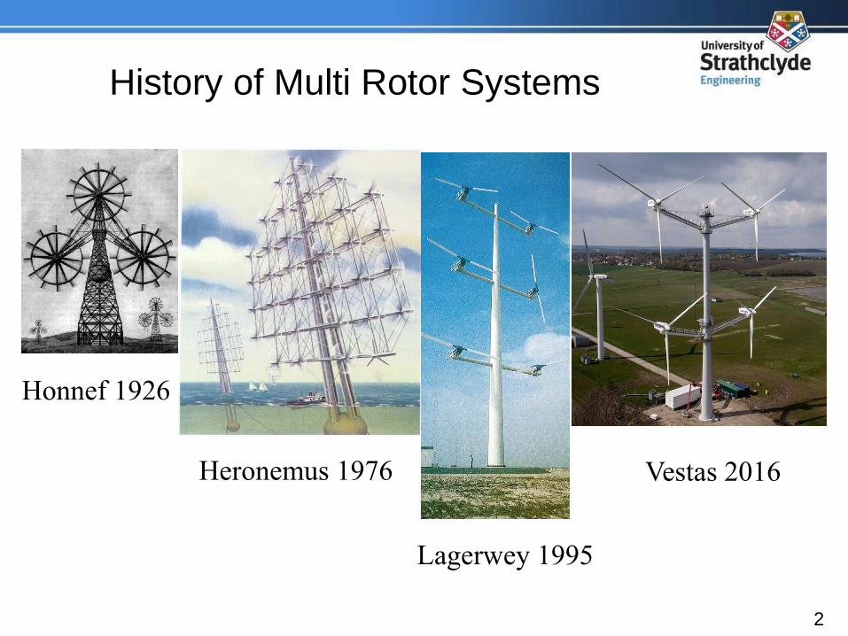
History of Multi Rotor Systems
Honnef 1926
Heronemus 1976
Lagerwey 1995
Vestas 2016
3
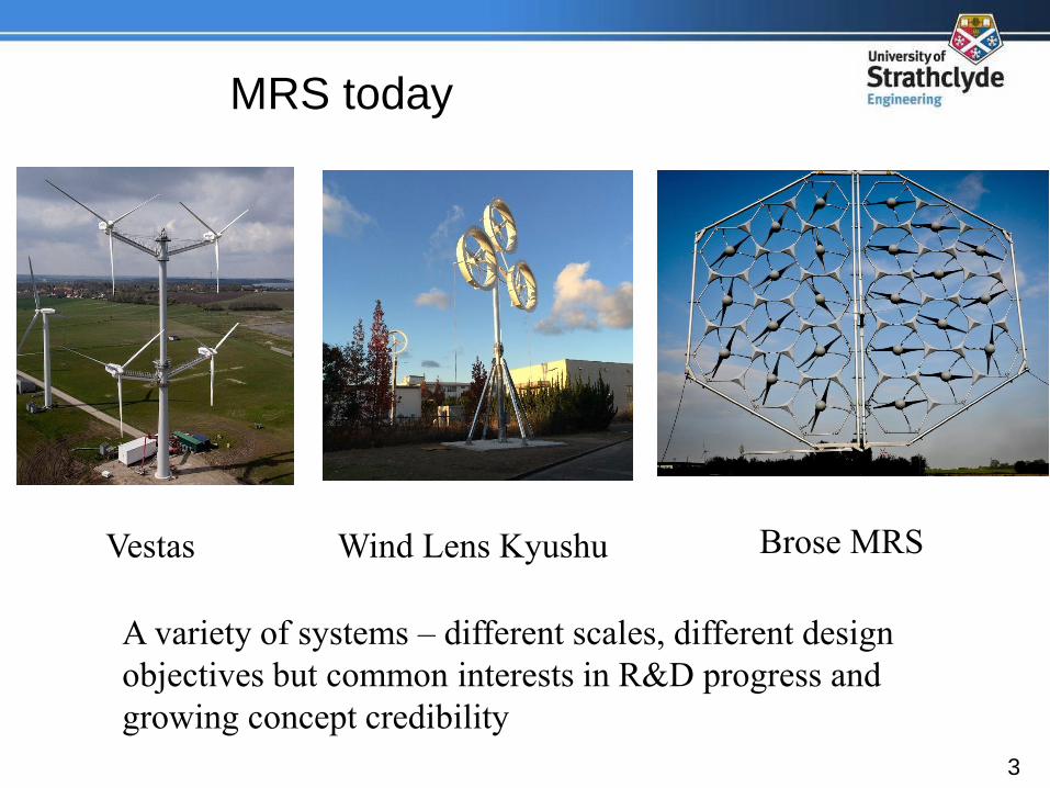
MRS today
Vestas
A variety of systems – different scales, different design
objectives but common interests in R&D progress and
growing concept credibility
Wind Lens Kyushu Brose MRS
4
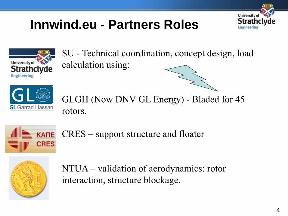
Innwind.eu - Partners Roles
SU - Technical coordination, concept design, load
calculation using:
GLGH (Now DNV GL Energy) - Bladed for 45
rotors.
CRES – support structure and floater
NTUA – validation of aerodynamics: rotor
interaction, structure blockage.
5
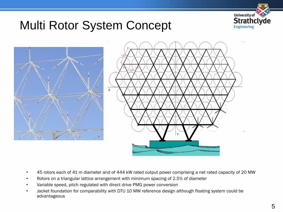
Multi Rotor System Concept
• 45 rotors each of 41 m diameter and of 444 kW rated output power comprising a net rated capacity of 20 MW
• Rotors on a triangular lattice arrangement with minimum spacing of 2.5% of diameter
• Variable speed, pitch regulated with direct drive PMG power conversion
• Jacket foundation for comparability with DTU 10 MW reference design although floating system could be advantageous

6
Why Multi-Rotors?
National
Geographic 1976
7
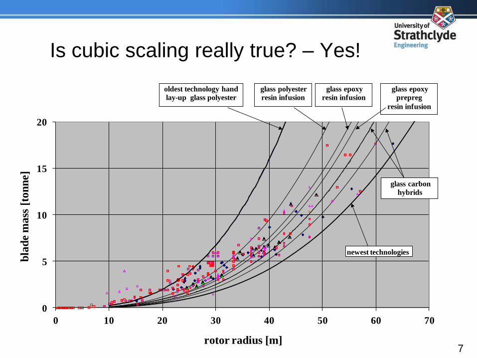
Is cubic scaling really true? – Yes!
0
5
10
15
20
0 10 20 30 40 50 60 70
bla
de m
ass
[to
nn
e]
rotor radius [m]
oldest technology hand
lay-up glass polyester
newest technologies
glass polyester
resin infusion
glass epoxy
resin infusion
glass epoxy
prepreg
resin infusion
glass carbon
hybrids
8
MRS Issues
a) Aerodynamic interaction of and array of closely spaced rotors
b) Mass and cost of support structure
c) Feasibility and cost of system yawing
d) Reliability with much greater total part count
9
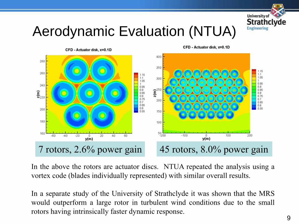
Aerodynamic Evaluation (NTUA)
7 rotors, 2.6% power gain
In the above the rotors are actuator discs. NTUA repeated the analysis using a
vortex code (blades individually represented) with similar overall results.
In a separate study of the University of Strathclyde it was shown that the MRS
would outperform a large rotor in turbulent wind conditions due to the small
rotors having intrinsically faster dynamic response.
45 rotors, 8.0% power gain
10
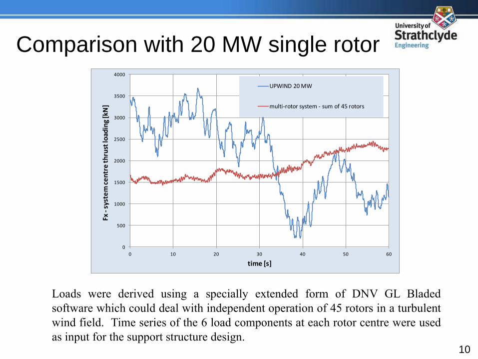
Comparison with 20 MW single rotor
0
500
1000
1500
2000
2500
3000
3500
4000
0 10 20 30 40 50 60
Fx -
syst
em
ce
ntr
e t
hru
st lo
adin
g [k
N]
time [s]
UPWIND 20 MW
multi-rotor system - sum of 45 rotors
Loads were derived using a specially extended form of DNV GL Bladed
software which could deal with independent operation of 45 rotors in a turbulent
wind field. Time series of the 6 load components at each rotor centre were used
as input for the support structure design.
11
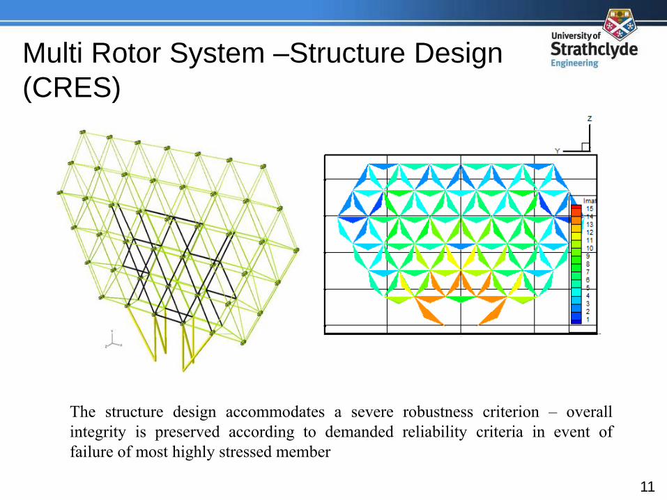
Multi Rotor System –Structure Design
(CRES)
The structure design accommodates a severe robustness criterion – overall
integrity is preserved according to demanded reliability criteria in event of
failure of most highly stressed member

12
Yaw System Design
• Development of a yaw system specification
• Evaluation of bearing arrangements and loads
• Effects of structure aerodynamic drag on yaw stability
• Feasibility of yawing operation using differential control of
rotor thrusts via blade pitch control (work in Innwind Task
1.4 ongoing in the PhD of Ewan McMahon of the University
of Strathclyde)
13
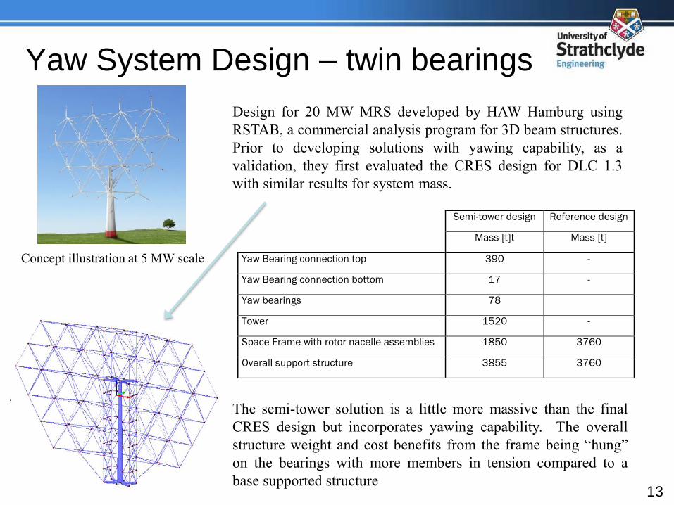
Semi-tower design Reference design
Mass [t]t Mass [t]
Yaw Bearing connection top 390 -
Yaw Bearing connection bottom 17 -
Yaw bearings 78
Tower 1520 -
Space Frame with rotor nacelle assemblies 1850 3760
Overall support structure 3855 3760
Yaw System Design – twin bearings
Concept illustration at 5 MW scale
Design for 20 MW MRS developed by HAW Hamburg using
RSTAB, a commercial analysis program for 3D beam structures.
Prior to developing solutions with yawing capability, as a
validation, they first evaluated the CRES design for DLC 1.3
with similar results for system mass.
The semi-tower solution is a little more massive than the final
CRES design but incorporates yawing capability. The overall
structure weight and cost benefits from the frame being “hung”
on the bearings with more members in tension compared to a
base supported structure

14
O&M of the MRS
a) The MRS is significantly different
from conventional technology in
O&M aspects.
b) A detailed O&M model for cost
optimisation of conventional wind
farms (Dinwoodie, PhD thesis) was
adapted to capture some of the most
significant differences of the MRS
c) This was supported by work on
availability and production (but
excluding cost impacts) by DTU in
Task 1.34 which highlighted
availability penalties if all turbines
required to be shut down during
maintenance.
15
O&M Results
a) In respect of availability, the O&M modelling of Dinwoodie
(Strathclyde) and of Gintautas (DTU, Task 13.4) was very similar
for the MRS although Dinwoodie predicted lower availability of
the DTU reference wind turbine (RWT) than the 97% assumed in
Innwind
b) The Dinwoodie model predicted similar O&M costs as were
attributed to the RWT in the Task 1.2 cost model and all results
(O&M cost) of the UoS model were subsequently scaled by a factor
so that agreement with the RWT was exact.
c) A 13% reduction in O&M cost was predicted for the MRS strongly
related to the avoidance of using jack-up vessels for any level of
rotor system failure.
16
MRS Feasibility and Cost?
a) Very large structure but not unusual. Similar to jacket above water.
Lattice structure in this and many other applications is the most efficient
in total weight of materials.
b) System yawing – somewhat new challenge, definitely feasible and looks
to be quite affordable
c) Aerodynamic interactions – apparently not adverse maybe even beneficial
d) Reliability with much greater total part count? Offset by reduced impact
of single rotor failures, improved unit reliability and overall maintenance
strategy. Potential for advantage rather than penalty in O&M costs
17
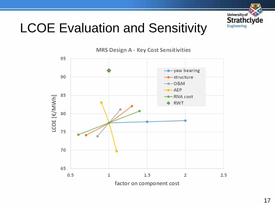
LCOE Evaluation and Sensitivity
18
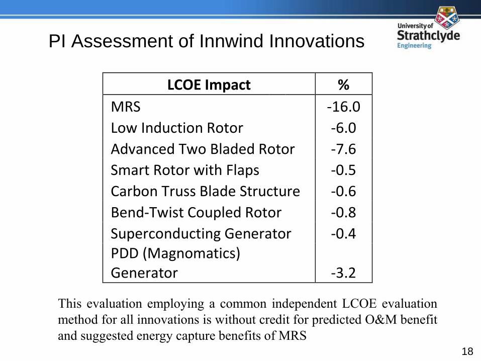
PI Assessment of Innwind Innovations
LCOE Impact %
MRS -16.0
Low Induction Rotor -6.0
Advanced Two Bladed Rotor -7.6
Smart Rotor with Flaps -0.5
Carbon Truss Blade Structure -0.6
Bend-Twist Coupled Rotor -0.8
Superconducting Generator -0.4 PDD (Magnomatics) Generator -3.2
This evaluation employing a common independent LCOE evaluation
method for all innovations is without credit for predicted O&M benefit
and suggested energy capture benefits of MRS
19
MRS Benefits?
a) Technology related LCOE reduction ~ 30% as in the present project (this
is relative to current offshore LCOE)
b) Further substantial LCOE reduction from greatly reduced commercial risk
related to turbine technology
c) Shortening of production and development cycles accelerating turbine
cost reduction and reliability improvement
d) Potentially much larger unit capacities than conventional technology
reducing the number of offshore sites per installed MW
e) Savings, perhaps ~ 80% reduction, in the use of non-recyclable glass-
resin products per installed MW
f) Faster market implementation
20
MRS – the Vision for Large Scale
~ 50 % reduction in cost of energy from offshore wind
roughly half (~25%) direct technology impacts as
suggested in Innwind
the rest from commercial and industrial benefits
21
MRS – The next steps?
• Enhanced and specially adapted modelling tools for aerodynamics,loads and O&M especially
• Detailed designs for fixed bed and floating offshore systems withspecific attention to assembly, installation, maintenance andoperational logistics
• Prototype design and testing

22
Thank you for your attention!