Embed Size (px)
Citation preview

®
MONOLITHIC MEMBRANE 6125® PRE-INSTALLATION AND APPLICATION GUIDELINES
American Hydrotech, Inc. www.hydrotechusa.com (312) 337-4998 3/2019


© Aug 2019 PAGE 1
I. GENERAL These pre-installation and application guidelines are intended as a guide to the products’ safe and proper storage, handling and application. MONOLITHIC MEMBRANE 6125®
Monolithic Membrane 6125® (MM6125®) is a rubberized asphalt product formulated from asphalt, oil, synthetic rubbers and inert clay. The membrane is packaged in cardboard cartons containing 1 cake of membrane weighing approximately 40 pounds each. Each cake is wrapped in polyethylene that is melted along with the membrane during heating and melting in a double shell melter. Monolithic Membrane 6125 is formulated containing up to 40% post-consumer recycled content. Monolithic Membrane 6125 is intended for use as a waterproofing/roofing membrane in applications such as roof decks, plaza decks, bridge decks, parking decks, reflecting pools, shower sub-floors, kitchen sub-floors, mechanical room sub-floors, foundation walls, mud slabs, tunnels, planters, vegetated (green) roofs, and blue roofs. APPLICATION AND PERFORMANCE ADVANTAGES OF MONOLITHIC MEMBRANE 6125 SPREADS THICKER Monolithic Membrane 6125 is applied at thicknesses of 215 mils (5.5 mm) and 180 mils (4.8 mm) vs.60-90 mils (1.5-2.3 mm) with most competitive membranes. This greater thickness: • allows for a wider variety of substrate conditions • increases crack bridging ability • enhances self-healing properties
FULLY BONDED Monolithic Membrane 6125 bonds to any sound concrete, masonry, steel or wood surfaces, and readily conforms to any surface irregularities, protrusions, corners, etc. Should damage occur, leakage can be more quickly traced and the membrane easily repaired since the membrane restricts the migration of water between it and the substrate. EASE OF FLASHING Reinforcement is not usually needed to bridge cracks up to 1/6” (1.6 mm). Over large cracks and at critical points and terminations, sheet reinforcing encapsulated between two coats of Monolithic Membrane 6125 provides triple protection. 100% SOLIDS Monolithic Membrane 6125 contains no solvents, there are no two-part systems to mix, therefore no on-site cure failures as with other products. COLD WEATHER APPLICATION Monolithic Membrane 6125 can be readily applied in temperatures down to 0°F (-18°C) on a clean, dry, frost-free surface. Monolithic Membrane 6125 exhibits excellent low-temperature flexibility and adhesion characteristics. SETS UP RAPIDLY Monolithic Membrane 6125 does not “cure”, rather simply cools, thus it is not affected by adverse weather such as rain, snow, or frost, immediately after application. Once the membrane is protected, the deck can be opened up to subsequent trades, thus speeding the job. TIE-INS Previously installed Monolithic Membrane 6125 remelts sufficiently when lapped with new material to form a monolithic bond. This makes MM6125 perfect for phased construction or accommodating future tie-ins. There are no seams that can fail with MM6125. SELF HEALING Self-seals minor construction damage for added margin of safety.

© Aug 2019 PAGE 2
RELIABILITY Over 50 years of proven protection against water intrusion in applications worldwide. Monolithic Membrane 6125 also conforms to CGSB (Canadian General Standards Board) -37.50-M89 and applicable ASTM (American Society for Testing and Materials) for rubberized asphalt membranes.
MEMBRANE PREPARATION Before Monolithic Membrane 6125 can be applied to an approved substrate, the material must first be melted, then further heated and mixed to develop its full physical properties. The rubber content of the membrane makes it necessary to use indirect heat in the melting. Therefore, a double-jacketed melter (unlike a standard single-shell asphalt kettle) must be used. On older melters, the outer jacket holds a heat transfer oil which, when heated by one or two propane burners, in turn heats the membrane held by the inner jacket. “Air-jacketed” melters are more common today as they eliminate the need for the heat transfer oil and also speed up the heating/melting time. A system of heat exchange tubes replaces the heat transfer oil in the shell of the melter.
Propane and diesel-fueled, as well as electrically operated, rubberized asphalt melters are available.
A mechanical agitator inside the melter keeps the melted material moving, ensuring the uniform transfer of heat throughout the membrane. The agitator is typically located at the bottom of the
inner shell and is preferably in the form of rocking or sweeping blades that is powered by a small gasoline or propane powered engine that is mounted on the melters frame.
Double-jacketed melters are typically equipped with temperature gauges so that the melter operator can continually monitor the temperature of the membrane – and in the case of oil-jacketed melters, the heat transfer oil. The safe operating temperature for Monolithic Membrane 6125 ranges from 350°F to 375°F (177°C-190°C).
CONTINUOUS HEATING AND AGITATION OF THE SAME MATERIAL FOR 6 HOURS OR MORE, WITH- OUT THE ADDITION OF FRESH MATERIAL, IS TO BE AVOIDED! IN NO CASE SHOULD TEMPERATURES IN EXCESS OF 400°F (204°C) BE IMPOSED ON THE MATERIAL! HYDROTECH DOES NOT MANUFACTURE OR SUPPLY DOUBLE-JACKETED MELTERS. THE RESPONSIBILITY FOR THE SAFE AND PROPER USE OF A MELTER, AND FOR CONTROLLING THE MEMBRANE’S TEMPERATURE WITHIN THE PROPER LIMITS, BELONGS EXCLUSIVELY TO THE APPLICATOR.
ENVIRONMENTAL CONDITIONS Monolithic Membrane 6125 can be installed in a wide temperature range. Application below 0°F (-18°C) (ambient temperature) is not recommended for the safety and comfort of the laborers and operation of mechanical equipment. Monolithic Membrane 6125 must be installed to a DRY and CLEAN substrate. The application of Monolithic Membrane 6125 should not proceed during inclement weather. At least one full day of good drying conditions must be allowed before the application of the membrane continues following a rain. Monolithic Membrane 6125 is not affected by rain, snow or frost immediately after application.
110 gallon melter shown

© Aug 2019 PAGE 3
II. PRODUCTS (DESCRIPTION AND USE) The components of the waterproofing/roof assembly are to be products supplied by American Hydrotech, Inc. or products acceptable to American Hydrotech, Inc. MEMBRANE • Monolithic Membrane 6125 (MM6125): a hot,fluid-
applied, rubberized asphalt material melted and spread on properly prepared substrates as a roofing or waterproofing membrane.
OTHER HYDROTECH SUPPLIED MATERIALS FLASHING/REINFORCING • Flex-Flash F: 1.3 oz/sqyd
spunbonded, polyester fabric used as the standard reinforcing sheet for MM6125.
• Flex-Flash UN: .060 inch (1.5mm) thick uncured neoprene rubber sheet used as heavy duty reinforcing for the MM6125 as well as the primary exposed flashing material.
• Flex-Flash MB: .160 inch
(4mm) thick torchable, modified asphalt sheet for exposed flashing. Available in smooth or granular top surface.
• Flex-Flash F Vertical: open weave fiberglass
reinforcing sheet for use in the FR (fabric reinforced) assembly for below-grade vertical walls.
• HydroSeal: liquid
resin flashing with fleece reinforcement to form a monolithic, self-flashing and self-adhering reinforced flashing membrane in conjunction with Hydrotech’s MM6125 membrane and flashing accessories for a variety of conditions that do not allow for typical membrane flashing termination requirements.
SURFACE CONDITIONER Asphaltic-based surface conditioner for concrete surfaces conforming to ASTM D-41 and/or CGSB 9M. Both solvent (regular and low-VOC) and water-based (no-VOC) materials are available. BONDING ADHESIVE VOC-compliant contact adhesive used to adhere Flex-Flash UN to an acceptable substrate. SPLICE TAPE / SPLICE TAPE PRIMER Butyl, self-adhering tape with appropriate primer, used to adhere Flex-Flash UN together at seams and laps. SEPARATION / PROTECTION COURSE • Hydroflex 10: a 0.45
inch thick, light-weight, reinforced, modified asphalt sheet
• Or other separation
/ protection material acceptable to Hydrotech
The separation/protection course is used to protect the membrane from light foot traffic and to separate the membrane from the insulation placed above it. The separation / protection course should only be used in roofing applications.

© Aug 2019 PAGE 4
PROTECTION COURSE • Hydroflex 30: a 0.90
inch thick, reinforced, modified asphalt sheet
• Or other approved
protection material acceptable to Hydrotech (i.e., root barriers installed as part of the Garden Roof Assembly)
The protection course is used to provide protection to the membrane from physical abuse. Additional protection may be required in areas where extreme physical abuse is anticipated. CAP SHEET • Hydrocap 160: a 0.160
inch thick, granular surfaced, reinforced, modified asphalt sheet
• Hydrocap 90: a 0.090
inch thick, granular surfaced, reinforced, modified asphalt sheet
The cap sheet is used to provide longer-term protection to the membrane and can serve as the exposed surface of the roof. Fire-rated Hydrocap 90 is required for a Factory Mutual approved roof assembly. Additional protection may be necessary in areas of high traffic or where heavy physical abuse is anticipated. Hydrocap is available with white/light grey granules. PREFABRICATED DRAINAGE/AIR LAYERS (OPTIONAL) • Hydrodrain 300, 302,
1000: drainage composite consisting of a crush-proof, “geo-net” core to which is bonded a non-woven filter fabric.
• Hydrodrain AL: an air layer consisting of a
crush-proof polyethylene core to which is bonded a non-woven filter fabric.
• Hydrodrain 400, 420, 700, 720, 990: drainage composite consisting of a “dimpled” core to which is bonded a non-woven filter fabric (400, 420, 720) or a woven filter fabric (700, 990).
The drainage composites are used to provide for the free drainage of water and are typically installed on top of the separation/protection or protection course. Hydrotech does not require drain mats for any warranty consideration. The air layer is used to provide a required air space between DuPont STYROFOAM insulation board and a concrete topping slab or other impervious topping to maintain a “diffusion open” condition. COLD-APPLIED LIQUID MEMBRANES • Liquid Membrane 6090: a two-part,
polybutadiene based liquid membrane. • Monolithic Membrane 7800: a one-part,
rubberized asphalt liquid membrane. Both cold-applied liquid membranes are used to complement the application of MM6125. The cold-applied products may be used to repair the MM6125 or to flash in details prior to the application of the membrane. They may be particularly useful on those occasions when a melter cannot be on site right away. The cold-applied products also can see limited use as full waterproofing membranes. Consult Hydrotech for specifics. INSULATION
• STYROFOAMTM: extruded polystyrene insulation of appropriate compressive strength – RoofMate (RM), Ribbed RM (40 psi), PlazaMate (PD), HI-40 (40 psi), HI-60 (60 psi) or HI-100 (100 psi).
Hydrodrain 300 depicted
Hydrodrain 400 depicted

© Aug 2019 PAGE 5
• Hydroguard: extruded polystyrene insulation (40 psi) panels with modified concrete surfacing – available in natural concrete gray, tan, red or green.
• Thermaflo: extruded
polystyrene insulation panels with drainage channels cut into one side covered with a filter fabric – available in several compressive strengths and thicknesses.
ARCHITECTURAL FINISHED CONCRETE PAVERS • Architectural Pavers: hydraulically pressed
concrete pavers available in an array of colors and finishes for use on roofs, terraces, plazas, etc.
BALLAST PAVERS • Ballast Pavers: pressed concrete pavers
designed to be used as ballast for insulation in a Protected Membrane Roof (PMR) assembly.
RELATED MATERIALS FILTER FABRIC (PMR ASSEMBLY) Acceptable fabrics to be placed on top of the DuPont STYROFOAMTM when stone ballast is to be used:
• PMR Stone Filter Fabric (white in color); as supplied by Hydrotech.
* SEE HYDROTECH TECH BULLETIN #3, “PROTECTING STYROFOAMTM INSULATION FROM HIGH TEMPERATURES”. LOOSE STONE BALLAST (PMR ASSEMBLY) Stone or gravel ballast is acceptable for this roof assembly. The stone or gravel shall be washed and shall be freeze-thaw resistant. The gradation of the ballast shall be similar to ASTM D48-80,
gradations #5, #4 and #2. PRECAST CONCRETE PAVERS (PMR ASSEMBLY) Precast concrete pavers shall have a compressive strength of 3000 psi minimum and be of appropriate quality for roofing applications. Pavers shall weigh 18 psf minimum.

© Aug 2019 PAGE 6
III. PRECAUTIONS AND SAFETY Common sense is your first line of defense against personal injury - USE IT ! BE PREPARED - THINK AHEAD ! • Know the telephone number and location of the
nearest hospital and/or ambulance service in case of an emergency. Post the telephone numbers in a convenient location or carry them with you so you can access them quickly.
• Have a complete first aid kit on hand. Make sure
everyone knows how to use it. • Have within easy reach a properly rated, fully
charged fire extinguisher. KNOW HOW TO USE IT! • These instructions are not comprehensive. All
OSHA regulations, local codes and requirements should be followed.
FIRE EXTINGUISHER RATINGS: “A” For use on ordinary combustibles (wood, paper and cloth) “B” For use on flammable liquids (oil, gasoline, paint and grease) “C” For use on electrical equipment (motors, controls, panels and wiring) “D” For use on combustible metals (magnesium, sodium and potassium) WEAR THE PROPER CLOTHING • High-top work shoes with thick rubber or
composition soles. • Properly fitting pants without cuffs. • A long-sleeve shirt, buttoned at the cuffs and
within one button of the collar. • Gloves with snug fitting wristlets - no gauntlets. • Goggles or face shields - where required
(around melter). • Hard hat - to be worn at all times when there is
a hazard above. MELTER SAFETY • Check with the melter manufacturer for
instructions covering the melters proper operating procedures, safety and maintenance BEFORE firing it up.
• A properly rated, fully charged fire
extinguisher should be within easy reach of the melter (B/C rated extinguisher is recommended).
• Proper clothing is essential when working around or near a melter.
FIRST AID FOR BURNS • Cool the burn area with plenty of water.
DO NOT USE ICE ! • Do not attempt to remove membrane or
charred clothing from burn area. • Get burn victim to a doctor immediately
for first aid treatment. SOLVENTS AND ADHESIVES (when working with Flex-Flash UN)
• All solvents and adhesives should be properly stored and kept in their original containers, with the original labels intact.
• Handle all solvents and adhesives with
care. Familiarize yourself with the materials you will be working with beforehand. Know their hazards, any precautions, which should be taken, and the first aid required when contact is made with skin, eyes or when inhaled or swallowed.
• When working with or around solvents or
adhesives - NO SMOKING !!! • Only use solvents or adhesives in well
ventilated areas. If existing ventilation is poor utilize fans to provide air circulation.
• Have within easy reach a properly
rated, fully charged fire extinguisher. TORCHES AND BURNERS (when working with Flex-Flash MB)
• Check with the torch manufacturer for instructions covering the torches proper operating procedures, safety and maintenance BEFORE firing it up.
• At all times follow the Safety Guidelines
as published by the Asphalt Roofing Manufacturers Association (ARMA).
• Always have fire extinguishers readily
available.

© Aug 2019 PAGE 7
• Make sure the torching equipment is in good working order and that all torches have support stands.
• Do not allow the flame to come into contact
with the gas hoses. • Material can smolder for hours before igniting -
check all sources of observed smoke after completing the membrane’s installation.
• Use good hoisting techniques for hoisting gas
tanks to elevated areas. DO NOT fasten rope or cable around the valve area of the gas tank.
SAFETY DATA SHEETS • Safety Data Sheets are available on all products
sold by Hydrotech and are available on the Hydrotech website or upon request.

© Aug 2019 PAGE 8
IV. TOOLS AND EQUIPMENT (REQUIRED/RECOMMENDED) • Melter: A double-jacketed, oil bath or air jacketed
melter with mechanical agitation specifically designed for the preparation of hot, fluid-applied, rubberized asphalt materials MUST be used. Melter must be capable of maintaining the membrane temperature between 350°F and 375°F (177°C-190°C). Consult the melter manufacturer for specific instructions covering the melters proper operating procedures and safety and maintenance.
• Heat transfer oil, for oil bath melters, must have a
safe operating temperature range up to 550°F (288°C) and a flash point in a closed system of 600°F (315°C) or greater.
• Propane gas, diesel fuel or adequate electric
service (depending on melter type) • Gasoline (for gasoline powered agitator motor) • Flint striker • Dip thermometer (for checking membrane
temperature) • Brooms and shovels • Back-pack blower or air compressor (for blowing
clean the deck) • Industrial-quality, hand-held sprayer (for
application of surface conditioner) • White or unleaded gas (for “cutting” of surface
conditioner if needed) • Screwdrivers, hammer, pliers, wrenches, utility
knives, etc. • 5 gallon pails with safety handles (for
transporting and applying hot membrane) • 4 wheeled cart (for transporting pails of material
over larger distances) • Tape measure and chalk line (for gridding the
deck)
• Rubber squeegees (6” & 18” wide x 2” deep x 1/4” thick, flat bladed) and poles
• Paddles, brushes, trowels (for detail work)
• Thickness gauge capable of measuring to
mils (0.001”) and/or 32nds of an inch
• Large nap roller mops on poles and
membrane trough (for application to vertical surfaces)
• Brushes, paint rollers, seam rollers (for
detailing with Flex-Flash UN if necessary) • Propane tank and torch and trowels (for
detailing with Flex-Flash MB if necessary)
Hydrotech’s thickness gauge
© Aug 2019 PAGE 9
V. SUBSTRATES
CONCRETE (CAST IN PLACE) There are several different types of concrete (cast in place) used in construction. Some are acceptable substrates for Monolithic Membrane 6125, others are not. In general, Hydrotech is looking for a concrete substrate that has a compressive strength of 2,500 psi minimum with a density of no less than 90 pcf. STRUCTURAL WEIGHT CONCRETE: Made with aggregates such as sand, gravel and crushed stone, structural weight concrete will have a density of 135-160 pcf and will retain 3% to 5% moisture by volume when fully cured. An IDEAL substrate for MM6125. Hydrotech recommends a cure/drying time of 28 days, 14 days minimum. Depending on conditions (i.e., ambient temperature, humidity) the concrete may be dry enough to receive application of the membrane in less than the 14 day minimum recommendation. Contact Hydrotech’s Technical Services Department for additional information. LIGHTWEIGHT STRUCTURAL CONCRETE: Made with aggregates such as expanded shale, clay, slate or slag, lightweight structural concrete will have a density of 90-115 pcf, and will retain 5% to 20% moisture by volume when fully cured. An ACCEPTABLE substrate for MM6125 with certain
limitations. Due to the high moisture content of lightweight structural concrete, a cure/drying time of 60 days is recommended, with a 28 day minimum, before application of the membrane is to begin. LIGHTWEIGHT INSULATING AND/OR CELLULAR CONCRETE: Made with aggregates such as vermiculite, perlite, pumice, scoria or diatomite, light-weight insulating concrete will have a density of 15-90 pcf and will retain more than 20% moisture by volume when fully cured. This high moisture content can create bonding and pinholing/blistering problems for the membrane and the low density (less than 110 pcf) may create bonding problems due to the weak, non-durable surface that results. These factors make lightweight insulating concretes UNACCEPTABLE substrates for MM6125. CONCRETE SURFACE FINISH
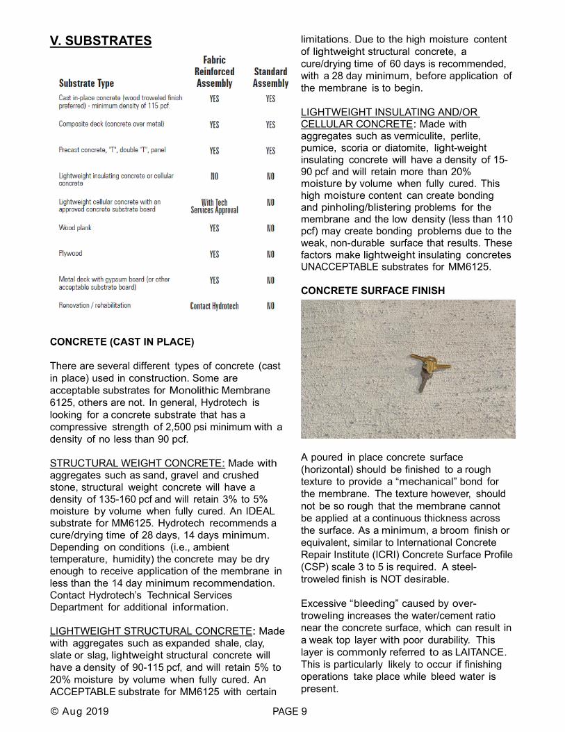
A poured in place concrete surface (horizontal) should be finished to a rough texture to provide a “mechanical” bond for the membrane. The texture however, should not be so rough that the membrane cannot be applied at a continuous thickness across the surface. As a minimum, a broom finish or equivalent, similar to International Concrete Repair Institute (ICRI) Concrete Surface Profile (CSP) scale 3 to 5 is required. A steel-troweled finish is NOT desirable. Excessive “bleeding” caused by over-troweling increases the water/cement ratio near the concrete surface, which can result in a weak top layer with poor durability. This layer is commonly referred to as LAITANCE. This is particularly likely to occur if finishing operations take place while bleed water is present.

© Aug 2019 PAGE 10
This weak concrete surface can inhibit the bond of Hydrotech’s MM6125 to the concrete and must be removed. SEE SECTION VI (6) “SPECIAL CONCRETE SURFACE PREPARATION” FOR ADDITIONAL INFORMATION. CONCRETE CURING TECHNIQUES Probably the most important factor in assuring that the concrete will attain its greatest strength and durability is the extent to which it has CURED. The curing process, known as HYDRATION, is especially critical during the first few days when the evaporation of water from the concrete is especially rapid. During this time, it is important to retain as much water within the concrete as possible. Several methods are commonly used for doing this. WATER CURING: Water curing is probably the most effective curing method. However, close continuous supervision is required to make sure that cycles between wetting and drying of the concrete are absolutely avoided. Water curing can be accomplished by “ponding”, which covers the slab with water held in place by a dike around the perimeter. “Spraying” or “Fogging” of the concrete keeps it wet through a system of hoses and nozzles that soak the concrete surface with a continual spray or mist of water. WET COVERINGS: Burlap fabric has been successfully used to keep a concrete surface wet during curing. The burlap must be carefully placed, leaving no concrete exposed, and then kept wet. Other wet coverings include earth, sand, hay, straw and sawdust. However, they are messy and more labor intensive, and therefore less practical. The wet covering method also poses a special risk. If allowed to dry out, these materials can actually act as a blotter and speed up the drying of the concrete. PAPER SHEETS: Paper sheets are a third method of curing concrete. Water-pervious papers require the periodic addition of water to replace water lost through evaporation. Impervious papers require no additional water, acting as a vapor barrier and
thereby preventing evaporation of the mix water. With both types of paper, the concrete surface should be thoroughly wetted before they are applied. The sheets must overlap by several inches and must be weighted in place to insure close contact with the concrete surface. PLASTIC SHEETS: Similar to water-impervious paper sheets, plastic sheets form a vapor barrier that seals moisture in. Light weight (as little as 20 lb/1,000 sq ft) makes plastic extremely practical and highly labor efficient. LIQUID MEMBRANE CURING COMPOUNDS: Liquid membrane curing compounds have become increasingly popular due to their ease of application and low material cost. Some are suitable for use when MM6125 is to be used, while others should be avoided. Ideally, MM6125 is best applied when traditional methods of concrete curing have been used (i.e. water curing, wet coverings, paper and plastics sheets). Most liquid membrane curing compounds are normally applied with a hand-held or power sprayer after the concrete has received its final finish and the water sheen on its surface has disappeared. The timing of the application is very critical. If the compound is applied when standing water is present, it will not be able to form the continuous film necessary to prevent evaporation of the water. Weak, improperly cured concrete results. If the curing compound is applied to a surface which has lost some of its mix water, it will be absorbed into the concrete and the result will be equally weak and improperly cured concrete. (Fortunately, when concrete surface has lost some of the mix water, it can be fogged down to seal the pores before the curing compound is applied) Normally, a single application of a liquid membrane curing compound is applied according to the product manufacturer’s specification. However, two lighter applications applied at right angles to each other can better assure complete coverage - reducing the chances that the material will pond in some areas while being missed altogether in others. In addition, many manufacturers suggest that lighter

© Aug 2019 PAGE 11
applications be applied when a subsequent material (like MM6125) is to be applied to the concrete. Conventional liquid membrane curing compounds of wax or resin bases only provide a curing function, synthetic products may also harden, seal and dustproof a concrete surface. The following details these products in relationship to their use with MM6125. SODIUM SILICATE BASED CURING COMPOUNDS: are recommended above any other liquid membrane curing compound for use with MM6125 because they leave no film or residue (when properly applied) which can interfere with MM6125’s ability to bond to the concrete surface. These compounds react with the free lime and other materials in the concrete mix to form an insoluble gel within the pores of the concrete, which greatly retards the evaporation of the mix water and provides a hard, dust-proof surface. ACCEPTABLE RESIN BASED CURING COMPOUNDS: form a film which can take 45-60 days to oxidize and flake off when exposed to the elements and foot traffic. A questionable bond is achieved between MM6125 and the concrete as long as the film is present. It can however, be removed by brushing down the surface with a wire brush or washing the surface with a light solution of muriatic acid or trisodium phosphate (TSP). The surface should then be rinsed and allowed to dry. Provided the film is TOTALLY removed prior to the application of MM6125, resin-based compounds MAY BE ACCEPTABLE. WAX BASED CURING COMPOUNDS: cease to be effective as curing agents after about 28 days yet take from 90 to 120 days to dissipate when exposed to the elements and traffic. The wax residue or film is difficult to remove and will interfere with the bond of MM6125 to the concrete. Wax based compounds ARE NOT ACCEPTABLE. WAX/RESIN BASED CURING COMPOUNDS: are not suitable for use on concrete that is to receive a subsequent application of MM6125. The wax component of this compound inhibits the adhesion of any future coating for the concrete. Wax/resin-based compounds ARE NOT ACCEPTABLE.
AND CHLORINATED RUBBER BASED CURING COMPOUNDS: leave a permanent film on the surface which may prevent MM6125 from achieving an adequate bond with the concrete surface. Acrylic and chlorinated rubber- b a s e d compounds ARE NOT ACCEPTABLE. The use of any liquid membrane curing compound in conjunction with Monolithic Membrane 6125 must be approved in advance and IN WRITING by Hydrotech on a project by project basis. Consult the Technical Services Department of American Hydrotech when a liquid membrane curing compound is intended for use. FORM RELEASE AGENTS: Form release agents are used to prevent concrete form sticking to the form work and facilitates faster and cleaner stripping of the forms. Typically, these release agents are spray applied to the forms prior to their erection. Form release agents over-applied to a form may transfer to the concretes’ surface cast against it. This could cause problems for Hydrotech’s MM6125 from the standpoint of achieving a good bond to the concrete surface. Hydrotech does not recommend the use of any petroleum, wax, resin or silicone-based form release agents, due to the potential adhesion problem if this agent should transfer to the concretes’ surface. Some manufacturers of form release agents do claim, however, that their products will provide a concrete surface free of residue that would impair the bond of paint or other subsequent concrete coating materials, provided their product is applied according to their specifications. Strict compliance to the manufacturers’ specified application rate is critical. If a form release agent transfers to the concrete surface the agent MUST be removed, as recommended by the manufacturer of the agent, prior to the application of the MM6125. Frequent bond checks should be conducted initially and

© Aug 2019 PAGE 12
throughout the application of MM6125 to verify that a good bond is being obtained. PRECAST CONCRETE Precast concrete is typically made of structural weight concrete and is generally an excellent substrate for the application of MM6125. Filling and/or reinforcing of the joints between individual precast panels is typically required. CONCRETE MASONRY UNITS
Concrete masonry units (CMU) used in foundation walls, planter walls, parapets, etc., are an acceptable substrate for MM6125. All CMU joints shall be struck flush prior to the application of the membrane. This type of installation requires a fabric reinforced membrane assembly, where one coat of membrane is applied to the concrete block units at a minimum thickness of 90 mils (2.3mm) into which a layer of Flex-Flash F (spunbonded polyester) fabric is embedded, followed by another coat of membrane at 125 mils (3.2mm) minimum. SEE SECTION VIII (8) “MONOLITHIC MEMBRANE 6125 APPLICATION” FOR ADDITIONAL INFORMATION. If the concrete block units are first parged with concrete to a thickness of 1/2” (12.7mm) minimum, the standard membrane assembly of a single 180 mil thick coat would be adequate. WOOD PLANK An acceptable substrate for MM6125. Minimum thickness 3/4” (19mm). Adequate structural support is required to limit deflection and movement between planks. Tongue and groove joints are required. Wood must be free of any special chemical treatments or other applications which would affect MM6125’s ability to bond to it.
This type of installation requires a fabric reinforced membrane assembly, where one coat of membrane is applied to the wood plank at a minimum thickness of 90 mils (2.3mm), into which a layer of Flex-Flash F (spunbonded polyester) fabric is embedded, followed by another coat of membrane at 125 mils (3.2mm) minimum. SEE SECTION VIII (8) “MONOLITHIC MEMBRANE 6125 APPLICATION” FOR ADDITIONAL INFORMATION. PLYWOOD
An acceptable substrate for MM6125. Minimum thickness 1/2” (12.7mm). Adequate structural support is required to limit deflection and movement between plywood joints. Tongue and groove joints are required. Plywood should be secured to the structure with screw-type fasteners – not nails. Wood must be free of any special chemical treatments or other applications, which would affect MM6125’s ability to bond to it. This type of installation requires a fabric reinforced membrane assembly, where one coat of membrane is applied to the plywood at a minimum thickness of 90 mils (2.3mm), into which a layer of Flex-Flash F (spunbonded polyester) fabric is embedded, followed by another coat of membrane at 125 mils (3.2mm) minimum. SEE SECTION VIII (8) “MONOLITHIC MEMBRANE 6125 APPLICATION” FOR ADDITIONAL INFORMATION. For extended roofing warranties (>10 years), pre-stripping the joints with MM6125 and Flex- Flash F is required prior to the application of the MM6125-FR membrane assembly.

© Aug 2019 PAGE 13
GYPSUM OR CEMENT BOARD OVER METAL DECKING
An acceptable substrate for MM6125. Cement boards must have a m in imum th ickness o f ½” (13mm) . Gypsum board must be fire rated type X board, minimum 5/8” (16 mm) thickness. Gypsum board materials that do not have any facer are preferred. Both traditional paper-faced and fiberglass-faced products with treated cores are acceptable but require special handling during application to prevent the delamination of the facer. The board must be mechanically fastened to minimum 22-gauge metal decking with appropriate screw type fasteners as directed by project specifications or local building codes. At a minimum there should be 10 fasteners per 4’ x 8’ board. Adequate structural support is required to limit deflection and movement. This type of installation requires a fabric reinforced membrane assembly, where one coat of membrane is applied to the board at a minimum thickness of 90 mils (2.3mm), into which a layer of Flex-Flash F (spunbonded polyester) fabric is embedded, followed by another coat of membrane at 125 mils (3.2mm) minimum. SEE SECTION VIII (8) “MONOLITHIC MEMBRANE 6125 APPLICATION” FOR ADDITIONAL INFORMATION. For extended roofing watertightness warranties (>10 years), pre-stripping the joints with MM6125 and Flex-Flash F is required prior to the application of the MM6125-FR membrane assembly.
POURED IN PLACE GYPSUM Not Acceptable.
TECTUM Not Acceptable. METAL
An acceptable substrate (flat metal sections not ribbed decking) for MM6125. Metal must be free of oil, rust, paint or coatings which may inhibit the bond of the membrane.
© Aug 2019 PAGE 14
VI. SPECIAL CONCRETE SURFACE PREPARATION Typically, the cleaning of a new concrete surface will consist of thoroughly sweeping the surface of all dirt and construction debris and then blow-cleaning to provide a surface acceptable for the application of MM6125. There are several instances when the typical simple cleaning is not adequate and additional preparation time and materials are required. This additional surface prep is typically required when the one or more of the following conditions is encountered: • After the tear-off of existing
roofing/waterproofing materials • If laitance is encountered on the concrete surface • When certain liquid membrane curing
compounds have been used • When certain form release agents have been
used • If there has been a spill or leak of oil and/or
other surface contaminants The following information has been adapted from procedures developed by the American Concrete Institute and compiled from Hydrotech’s experience with respect to the cleaning, preparation and repair of concrete. CLEANING CHEMICAL CLEANING Chemical cleaning may be necessary as a preliminary step to other methods of cleaning to remove substances such as oil, grease, dirt and some surface treatments. This method typically requires a vigorous scrubbing with solutions of caustic soda, trisodium phosphate or detergents especially formulated for use on concrete. Flush with water (not solvent) to rinse away all traces of the cleaning material as well as the contaminant. Solvents should not be used in the flushing as they tend to dissolve the contaminant and spread it over the deck. ACID ETCHING Once considered a reliable method for preparing a
concrete surface, acid etching is not as dependable as mechanical cleaning methods have become and is now typically only used if no other alternative is possible. If grease or oil residue are part of the contamination, precleaning before acid etching should be done according to the chemical cleaning method described above. The etching procedure itself is typically performed with a 10/90 or 20/80 dilution ratio of commercial grade hydrochloric (muriatic) acid in water, applied to the concrete at an average rate of 1 quart per square yard. If chlorines cannot be used (if corrosion of reinforcing steel is a concern) a 15% solution of phosphoric acid may be used. The acid solution is sprinkled or sprayed onto the concrete’s surface and is worked in with stiff brooms or brushes. When the foaming action subsides (typically 3 - 5 minutes) the surface is flushed with water while scrubbing continues. A second treatment may be required to remove heavily contaminated areas. Test with litmus or pH paper to verify that the water flushing has been adequate. When a near neutral condition exists, the surface can be allowed to dry. Proper precautions and personal protective equipment should be used at all times when working with harmful chemicals. Consult the specific manufacturer for recommendations regarding the safe use of their product. BLAST CLEANING Blast cleaning - whether using a high-pressure water jet with or without an abrasive like sand or just a dry abrasive like sand, is one of the more effective ways of removing dirt, concrete laitance or other weak surface material and some residue of existing roofing/waterproofing materials. High pressure washing without abrasives alone may not be adequate for the removal of some of these materials since it removes little surface material as compared to the wet or dry abrasive blast methods.

© Aug 2019 PAGE 15
Oil or grease that has soaked into the concrete should first be removed with a chemical cleaning process before blast cleaning. A blasting method should be selected (in accordance with local environmental restrictions and codes) which best does the job resulting in the surface of the concrete being abraded to the extent that small aggregate particles are exposed and a SOUND, STRONG SUBSTRATE remains. The air compressor used in the blasting process must have efficient oil and water traps to make sure that the air it supplies is clean. Clean water must be used in wet blast cleaning. Wet blast cleaning offers a clean-up advantage over dry methods as dust collection is typically more time consuming and difficult than water removal. SCARIFICATION/SHOTBLASTING/GRINDING These and other mechanical methods are probably the most efficient methods of removing weakened layers of concrete (i.e. laitance) and residues of pre-existing roofing/waterproofing materials such as asphalt, urethanes, adhesives, etc. SCARIFIERS typically employ a drum that has a series of blades attached. The drum spins at high speeds thus allowing the blades to tear into the surface of the concrete or coating. Scarifiers can be particularly useful on rubber-type and asphaltic materials that may “gum” up when other machines are used. SHOTBLASTERS much like a sand blasting, utilizes metal shot or pellets, of various sizes, that are shot at high speed at the decks surface thus breaking up the concrete or coating. The surface texture required, and type of material being removed determines what size shot is used. Shotblasters may not be as effective on rubber-type materials and in some cases asphalt products, as scarifiers would be, since the shot would tend to simply bounce off the surface. Shotblasters also offer a clean-up advantage in that the shot is recovered into the machine and in some cases the dust and debris can be vacuumed up by the machine or attachments.
GRINDING machines typically employ a simple wheel that spins a series of blades that cut up or grind a surface. Grinding is usually only appropriate to further prepare concrete surfaces to remove weak areas or to grind down high spots and ridges. Grinders typically cannot do an adequate job on removing existing roofing/waterproofing materials as most would simply “gum” up due to the heat generated by the friction of the grinding wheel. One or more of the above techniques may also be required for removal of the following: LAITANCE Laitance is a layer of weak, non-durable cement and fine elements of aggregate that has been brought to the surface by overworking or improper finishing of the concrete surface. Usually lighter in color than the rest of the concrete surface, one can easily check for the presence of laitance by scraping the surface of the concrete with a putty knife or any other hard metal object. The surface will easily break away from the sound concrete below or grooves will easily be made in the surface. Laitance must be totally removed prior to the application of MM6125. TEAR-OFF OF EXISTING ROOFING / WATERPROOFING MATERIALS Every effort should be made to remove all existing solid material from the deck. The use of spud bars and/or scarifiers and/or shotblasters is typically recommended. In no case should any loose, blistered, wet or damaged material be left on the deck. There must be no areas where water is left trapped underneath or within plies of any existing material. If some existing materials remain on the deck after thorough cleaning as described above, they may be acceptable according to the following guidelines. Consult Hydrotech’s Technical Services Department for a review of exact conditions.

© Aug 2019 PAGE 16
ASPHALT and MODIFIED ASPHALT BUILT-UP ROOFING
All insulation and felt or membrane layers must be removed completely, down to the last coating of asphalt directly applied to the deck. Scarifiers and/or shotblasters have proven quite effective in removing the last stubborn layer of asphalt. More consideration can be exercised for leaving some solid membrane material on the deck that is firmly bonded to the concrete since these materials are typically compatible with MM6125. All continuous flashing materials must be removed 100%. If new flashings are to be adhered with bonding adhesive, the substrate must be 100% cleaned or a suitable recovery material (i.e., plywood, cement or gypsum board) should be installed. COAL TAR BUILT-UP-ROOFING All insulation and felt or membrane layers must be removed completely, down to the last coating of coal-tar directly applied to the deck. Scarifiers and/or shotblasters have proven quite effective in removing the last stubborn layer of coal-tar. Some solid membrane material may be left on the deck that is tightly bonded to the concrete, however, more care must be exercised as the coal tar pitch may not be compatible with the MM6125. Age of the old membrane and any volatiles remaining should be determined. Test patches of new MM6125-FR may be required. Consult Hydrotech. All continuous flashing materials must be removed 100%. If new flashings are to be adhered with bonding adhesive, the substrate must be 100% cleaned or a suitable recovery material (i.e. plywood, cement or gypsum board) be installed. LIQUID-APPLIED MEMBRANES OR COATINGS All loose, blistered and damaged areas must be removed completely. Any trapped moisture must be located and exposed to facilitate drying.
Scarifiers work very well with the thicker (60+ mils, 1.5+ mm) membranes and some shotblaster manufacturers claim the same for their equipment. Both machines typically work equally well on the thinner deck coating materials. More consideration can be exercised for leaving solid asphalt material on the deck that is firmly bonded to the concrete since asphalt is compatible with MM6125. PEEL and STICK MEMBRANES All loose, blistered and damaged material must be removed. Any areas where water or moisture is trapped beneath the membrane must be located and exposed. If the entire membrane cannot be removed from the deck, at a minimum all laps and flashings must be cut out and removed and a torch must be used to burn off the layer of polyethylene on any material remaining. IS IT CLEAN ? One final check to determine if the concrete has been properly cleaned is to apply test patches of MM6125 to the concrete surface. Several test patches should be applied to different areas of the deck. The patches should be no less than 12” (305mm) square and be applied at no less than 125 mils (3.2mm) thick. The bond to the substrate can be checked immediately after the membrane cools and then should be checked again the next day. If a sound bond is achieved the application can typically proceed. However, frequent bond checks should be made during the application of the membrane to ensure the integrity of the overall installation. If a sound bond is not achieved, further deck preparation is typically required. IS IT DRY ? The same test patch procedures, outlined under “IS IT CLEAN?” above can be used to determine whether the concrete is dry

© Aug 2019 PAGE 17
enough to receive the MM6125. Excessive moisture within the concrete can be drawn to the surface during application by the heat of the membrane and even after application by the heat of the sun on the black membrane or by the vapor drive caused by the capillary action of the water wanting to escape. The result of excessive moisture on the MM6125 would be seen in the form of pinholing, blistering and/or loss of adhesion. If pinholing and/or blistering are observed, the application must be delayed until the concrete is shown to be dry enough. SEE SECTION VIII. “MONOLITHIC MEMBRANE 6125 APPLICATION” FOR ADDITIONAL INFORMATION. If loss of adhesion is observed, the application cannot proceed until the concrete is shown to be dry enough. In some cases, the test patches with MM6125 are not practical. In these instances, there are other methods that can be employed as aids in making the determination of whether the concrete is dry enough. ASTM D4263 “Standard Test Method for Indicating Moisture in Concrete by the Plastic Sheet Method”, reports a simple method for determining the presence of moisture in concrete. The standard recommends using an 18 X 18-inch square of 4 mil polyethylene sheet and 2 or 3-inch-wide duct tape. The sheet is taped to the concrete surface tightly, sealing all edges. This should be done when the surface temperature of the concrete and other ambient conditions is the same as those expected during membrane application. In addition, Hydrotech recommends doing several tests in different areas. The sheet should be protected from heat, direct sunlight and tearing. After at least 16 hours, remove the sheet and look for moisture both on the poly sheet and on the concrete. The presence of moisture is an indication that more drying time is required.SEE SECTION VIII. “MONOLITHIC MEMBRANE 6125 APPLICATION” FOR ADDITIONAL INFORMATION. If no moisture is present, the application can typically proceed. However, frequent bond checks
should be made during the application of the membrane to ensure the integrity of the overall installation. The use of moisture meters on site, or the laboratory analysis of core samples taken from the deck, are other methods used to determine the presence of moisture within concrete. These methods however, are best left to the professional who specialize in the procedures. As far as the amount of moisture that would be acceptable, while no specific and guaranteed number is currently known, Hydrotech believes that readings of less than 8% moisture by volume would be acceptable. REPAIR OF SURFACE DEFECTS Honeycombed and other defective concrete areas must be chipped away or removed down to sound concrete. Edges should be perpendicular or slightly undercut; NEVER feathered. After chipping, the area must be dampened with water to prevent absorption of moisture from the patching mortar. A bond coat is brushed into the surface, and when it begins to lose its water sheen, is followed by the premixed patching mortar. Leave the mortar slightly higher than the surrounding surface. Let an hour pass for initial shrinkage before finishing, then keep the patch damp so that it will properly cure as recommended by the manufacturer of the mortar. Using proprietary patching materials such as those containing polymers, can improve the adherence of the patch, but first must be approved for use by Hydrotech. Latex or epoxy modified repair mortars have been found to be acceptable provided they can be finished per Hydrotech’s recommendations. Tie-holes, after a thorough cleaning and dampening with water, should be completely filled with patching mortar.

© Aug 2019 PAGE 18
Fins, protrusions or other irregular projections from the surface of the concrete, should be removed by chipping, jackhammering, grinding or wire brushing. A reasonably flat surface is required so that MM6125 can be applied in a continuous monolithic coat. Smooth and gradual transitions between off-set surfaces must be provided.

© AUG 2019 PAGE 19
VII. DETAILING Hydrotech has developed a set of guideline details for installing MM6125 in waterproofing/roofing applications, which address standard and common detailing conditions. If conditions arise which cannot be handled by these standard guideline details, consult Hydrotech for assistance. All surfaces to which MM6125 and flashing is to be applied must be clean and dry. All transitions must be sharply formed having no irregular surfaces or edges. In both waterproofing and roofing applications, all critical detailing conditions are typically triple protected utilizing a reinforcing layer embedded into and top coated with MM6125 membrane. The reinforcing material must be firmly embedded into the initial coat of membrane before the second coat of membrane is applied to ensure positive adhesion, free of trapped air. In waterproofing applications, where the entire assembly including flashings are typically buried, it is not necessary to switch to “flashing” materials. The MM6125 membrane can be used as the continuous flashing with the appropriate reinforcing material. TYPES OF REINFORCING There are three types of reinforcing materials that are supplied by Hydrotech: • Flex-Flash F: a 1.35 oz/sq yd, spunbonded,
polyester fabric • Flex-Flash FV: an asphaltic coated, 10x20
woven fiberglass fabric (vertical below-grade only)
• Flex-Flash UN: a .060-inch-thick, uncured
neoprene sheet rubber Flex-Flash F is the standard duty reinforcing fabric used at cracks, construction joints, control joints and at all changes-in-plane and as directed by Hydrotech. (See Hydrotech’s Standard Guideline Details) NO PORTION OF FLEX-FLASH F CAN EVER BE LEFT EXPOSED OVERNIGHT!
Flex-Flash UN is the heavy duty reinforcing sheet which like Flex-Flash F can be used at all cracks, joints and change-in-plane but unlike the fabric must be used at drains and expansion joints or anywhere large, rough transitions occur as with metal plates. Flex-Flash UN is also used as the exposed flashing material. (See Hydrotech’s Standard Guideline Details) As reinforcing materials are completely encapsulated within coats of MM6125, no additional adhesives, sealants or application fastening techniques are required. Any other material being considered as reinforcing for MM6125 must be approved in advance by Hydrotech. TYPES OF EXPOSED FLASHINGS There are two types of exposed flashing materials supplied by Hydrotech: • Flex-Flash UN: a .060-inch-thick,
uncured neoprene sheet rubber • Flex-Flash MB: a .160-inch-thick, torchable,
modified asphalt flashing material. • HydroSeal: liquid applied resin flashing. In roofing applications, where MM6125 is to be used, it is typically good roofing practice to extend the flashings up above the finished roof surface 8 -12 inches. Parapets, curbs, pipes and walls are examples of where flashings must extend above the roof surface. Since MM6125 itself cannot be left exposed, Flex-Flash UN and Flex-Flash MB are typically used for all exposed flashing conditions. For conditions that do not allow for typical membrane flashing termination requirements (i.e., “H” columns, tube steel, etc.) HydroSeal liquid flashing may be used. (See Hydrotech’s Standard Guideline Details) Flex-Flash UN is typically adhered with Hydrotech’s Bonding Adhesive and the laps sealed with Splice Tape. Flex-Flash MB, being a modified asphalt material is typically applied by melting the asphalt on the backside of the sheet with a torch.
© AUG 2019 PAGE 20
HydroSeal Resin is mixed with a catalyst and combined with fleece reinforcement. (See the HydroSeal Tech Data Sheet for specific mixing and application instructions) SEE SECTION III (3) “PRECAUTIONS AND SAFETY” FOR INFORMATION ON SAFETY MEASURES WHICH SHOULD BE TAKEN WHEN WORKING WITH HAZARDOUS AND FLAMMABLE MATERIALS AND SYSTEMS. Any other material being considered as an exposed flashing for MM6125 must be approved in advance by Hydrotech. ADHESIVES AND SEALANTS (for use with Flex-Flash UN) BONDING ADHESIVE Hydrotech’s Bonding Adhesive is used specifically for bonding Flex-Flash UN to most clean, sound substrates (i.e. metal, concrete, wood, etc.). Bonding Adhesive is available in 5 gallon pails or 6 -1 gallon buckets. Bonding Adhesive MUST be thoroughly stirred before and during use. One gallon of adhesive is sufficient to cover 60 square feet of BOTH surfaces to be bonded. Application is typically done by brush or roller, applying an even coat on both the backside of the Flex-Flash UN and the substrate. When dry, but still tacky to the touch, the two materials can be mated together. Once contact is made it is impossible to reposition the Flex-Flash UN - so proceed with caution. Pressure should be applied to the entire bonded area to ensure a positive bond is achieved. Bonding Adhesive should not be used in temperatures below 32°F (0°C). For cold temperatures (below 65°F, 18.3°C) store the material at room temperature just prior to use. SPLICE TAPE Hydrotech’s Splice Tape is used specifically for bonding Flex-Flash UN to itself at seams and laps. Splice Tape is available as a 4-inch-wide by 100 foot long roll. Splice Tape Primer is typically applied with a roller or brush to the area of Flex-Flash UN membrane to be seamed on both mating surfaces of membrane at a rate of 350-
400 sqft/gallon each surface. 1 gallon of Primer would be enough to treat both mating surfaces of Flex-Flash UN for approximately 6 rolls of Splice Tape (600 ln.ft.). To achieve proper adhesion at ambient temperatures below 40°F, Splice Tape must be stored near room temperature and kept at 40°F or higher during use. In addition, a hot air gun should be used to heat; - the primed area as the Splice Tape is applied.
- the lap area prior to final rolling. When it is necessary to continue a Tape application after reaching the end of a roll or when cut, overlap subsequent Tape applications 1 inch minimum. Prolonged storage temperatures >90°F may impact product shelf life. Onsite, keep Splice Tape rolls boxed in a shaded, dry area until ready to use. Condensation may form on freshly applied Primer when ambient temperature is near the dew point. In such conditions, stop application, allow area to dry, and re-apply a thin coat of Primer when conditions allow. SPECIFIC DETAILING CONDITIONS All detailing, flashings and terminations shall be done in accordance with Hydrotech’s standard installation guidelines and details. Refer to Hydrotech’s standard guideline details for drawings depicting the following: SHRINKAGE CRACKS For cracks over 1/16” (1.6mm) but less than 1/4” (6.4mm) in width, apply membrane, 125 mils (3.2mm) thick, over the crack area. Center a 6” (152.4mm) wide strip of reinforcing (Flex-Flash F or UN) over the crack and embed firmly into the warm membrane. Apply another coat of membrane, 125 mils (3.2mm) thick, over the reinforcing sheet, totally encapsulating it in membrane.

© AUG 2019 PAGE 21
CONSTRUCTION OR CONTROL JOINTS Apply membrane, 125 mils (3.2mm) thick, over the joint area. Center a 6” (152.4mm) wide strip of reinforcing (Flex-Flash F or UN – see Hydrotech’s Guideline Details) over the joint and embed firmly into the warm membrane. Apply another coat of membrane, 125 mils (3.2mm) thick, over the reinforcing sheet totally encapsulating it in membrane. When installing MM6125-FR, pretreating construction or control joints is typically not necessary.
PRECAST JOINTS Side Joints: Fill the joints between precast panels with concrete or an acceptable repair mortar or sealant. Apply membrane, 125 mils (3.2mm) thick, over the joint area. Center a strip of reinforcing (Flex-Flash F or UN) over the joint, extending 3” (76.2mm) beyond both sides of the joint, and embed firmly into the warm membrane. Apply another coat of membrane, 125 mils (3.2mm) thick, over the reinforcing sheet totally encapsulating it in membrane.
End Joints: Fill the joints between precast panels with concrete or an acceptable repair mortar. Apply membrane, 125 mils (3.2mm) thick, over the joint area. Center a strip of reinforcing (Flex-Flash F or UN) over the joint, extending 9” (228.6mm) beyond both sides of the joint, and embed firmly into the warm membrane. Apply another coat of membrane, 125 mils (3.2mm) thick, over the reinforcing sheet totally encapsulating it in membrane. COMPOSITE DECK (PRECAST W/TOPPING SLAB) JOINT TREATMENT Side Joint Treatment: Method 1 - Saw cut the concrete topping slab to a depth 1/4 its thickness, directly over the joints of the precast. Apply membrane, 125 mils (3.2mm) thick, over the joint area. Center a 6” (152.4mm) wide strip of reinforcing (Flex-Flash F or UN) over the joint and embed firmly into the warm membrane. Apply another coat of membrane, 125 mils (3.2mm) thick, over the reinforcing sheet totally encapsulating it in membrane. Side Joint Treatment: Method 2 - Locate on the concrete topping slab where the precast joints are below. Apply membrane, 125 mils (3.2mm) thick, over this area. Center a strip of reinforcing (Flex-Flash F or Flex-Flash UN), 2 X the slab thickness plus 6” (152.4mm) in width, over the joint area and embed firmly into the warm membrane. Apply another coat of membrane, 125 mils (3.2mm) thick, over the reinforcing sheet totally encapsulating it in membrane. End Joint Treatment: Either Method 1 or 2, outlined above, may be used to detail this condition with the following changes: If Method 1 is followed, only Flex-Flash UN may be used, and it must be a minimum of 12” (304.8mm) in width. If Method 2 is followed, only Flex-Flash UN may be used, and it must be 2 X the slab thickness plus 12” (304.8mm) in width.

© AUG 2019 PAGE 22
EXPANSION JOINTS Expansion joints can be detailed a number of different ways, depending on the various structural and/or design considerations for each project. The descriptions below outline typical methods of how a typical expansion joint may be detailed using Flex-Flash UN and MM6125. Specific project requirements may dictate that these details be modified or abandoned altogether in favor of proprietary expansion joint materials and systems.
Expansion Joints < 1” (25.4 mm) In Width: (25% total designed movement) Apply membrane, 125 mils (3.2mm) thick, over the joint area. Center a strip of reinforcing (Flex-Flash UN only) over the joint, extending 3” (76.2mm) beyond both sides of the joint, and embed firmly into the warm membrane. Apply another coat of membrane, 125 mils (3.2mm) thick, over the reinforcing sheet totally encapsulating it in membrane. Expansion Joints > 1” (25.4 mm) but < 2” (50.8mm) In Width: (25% total designed movement) Lay a foam rod or tube (1” (25.4mm) larger in diameter than the joint width) over the opening of the joint. Apply MM6125 membrane, 125 mils (3.2mm) thick, up to the joint area. Embed a strip of reinforcing (Flex-Flash UN only) firmly into the warm membrane extending 6” (152.4mm) beyond one side of the joint. The Flex-Flash UN should then be laid over the foam rod and extend another 6” (152.4mm) beyond the other side of the joint, again
embedded into MM6125. Apply additional MM6125 over the Flex-Flash UN and install another strip of Flex-Flash UN, extending a minimum of 9” beyond both edges of the first layer of neoprene. Finally coat over the Flex-Flash UN except where it is looped up and over the foam rod, totally encapsulating the sheet edges. The anticipated movement of the deck at expansion joints is designed to be taken by the excess looped material (Flex-Flash UN). The detail should never be designed or constructed so that stress occurs within the flashing sheet itself. In roofing applications, it is advisable to curb the expansion joint detailing above the finished surface of the roof whenever possible. In waterproofing applications, the foam rod may be inserted slightly into the joint leaving at least half of the rod “proud” of the surface of the deck to provide a hump/water shed. Additional protection must be provided over the completed joint assembly to protect the detailing from subsequent backfilling and/or topping material installation. THESE DETAILS ARE EXTREMELY LABOR INTENSIVE AND SENSITIVE. CARE MUST BE EXERCISED IN THEIR CONSTRUCTION. THESE DETAILS ARE NOT INTENDED TO BE USED TO ACCOMMODATE FOR MOVEMENT IN EXCESS OF THE JOINT WIDTH OR DUE TO SEISMIC STRESSES. ROOF DRAINS

© AUG 2019 PAGE 23
With the clamping ring removed, apply membrane,125 mils (3.2mm) thick, around the drain, extending it from the edge of the drain bowl to a point 12” (304.8mm) out onto the deck beyond the edge of the deck flange, in all directions. Embed a sheet of reinforcing (Flex-Flash UN only) firmly into the membrane, centered over the drain bowl, while the membrane is still warm. The reinforcing should extend a minimum of 6” (152.4mm) beyond the edge of the deck flange in all directions. Slits should be cut to accommodate for the clamping ring bolts and the center of the reinforcing must be cut out. Re-install the drain clamping ring, making sure that the bolts are all properly tightened. NOTE: No protection course (Hydroflex 30, etc.) is to extend under the drain ring. Finish by coating over all the reinforcing, exposed beyond the clamping ring, with a 125 mil (3.2mm) thick coat of MM6125 totally encapsulating it. PENETRATIONS
Flash all penetrations (pipes, angles, vents, etc.) passing through the membrane. All penetrations must be rigid and properly secured to the deck or cast into the deck. The flashing seal must be made directly to the penetration passing through the membrane. The flashing should not be terminated to an intermediate element (metal flashing, insulation, surface treatment, etc.) which itself could fail and allow moisture to bypass the flashing and membrane. Flexible penetrations (i.e. lightning cable, plastic “smurf” tubes/conduits) must be enclosed in a
stable “goose neck” vent or other appropriate sleeve secured to the deck. The sleeve is then properly flashed in accordance with Hydrotech guideline details. As the performance of the MM6125 is jeopardized by temperatures greater than 180 degrees F (82.2 C), hot pipes must first be surrounded by an intermediate “cold” sleeve pipe that allows the flashing to be applied to it instead of directly to the hot pipe itself. EXPOSED FLASHINGS (i.e. CURBS, PARAPETS, WALLS, ETC.) MM6125 is not intended to be left exposed. For all exposed flashing conditions, Flex-Flash UN, Flex- Flash MB or HydroSeal must be used. For details that will be covered with subsequent cladding (stone, metal, etc.) the MM6125 may be extended as the flashing as well. FLEX-FLASH UN The Flex-Flash UN sheet when installed must extend out onto the deck a minimum of 3” and up the curb, parapet, wall, etc., a minimum of 8” (203.2mm) above the finished surface of the roof (whenever possible). The Flex-Flash UN must be adhered to the vertical surface with bonding adhesive, starting at a point 3” (76.2mm) off the deck and then up the full height at which point it must be properly terminated. The 3” (76.2mm) of unbonded Flex-Flash UN on the vertical and the 3” (76.2mm) that extends out onto the deck must be firmly embedded into MM6125, applied at a thickness of 125 mils (3.2mm). The Flex-Flash UN must be set into the membrane so that no air pockets develop, and it must be set tight into the corner so that no bridging (voids) is evident behind the flashing. Another coat of membrane at 125 mils (3.2mm) thick is then applied to cover the 3” (76.2mm) of flashing that extends out onto the deck, totally encapsulating it. Only the horizontal portion of the flashing sheet need be totally encapsulated in membrane.

© AUG 2019 PAGE 24
PROPER APPLICATION WITH ADHESIVES Bonding Flex-Flash UN to an acceptable substrate: • Thoroughly mix the bonding adhesive before
using and frequently while in use. • Apply the bonding adhesive evenly, without
globs or puddles, with a 9” (228.6mm) wide short nap roller or 4” (101.6mm) wide brush to both the flashing sheet and the substrate at a rate covering approximately 60 square feet (5.6m2) (both surfaces) per gallon. DO NOT APPLY BONDING ADHESIVE TO A SPLICE (LAP) AREA.
• Allow the bonding adhesive to dry until it is tacky
but will not slide when pushed with a finger or string up when touched with a dry finger.
• Roll the coated membrane onto the coated
substrate, avoiding wrinkles. • To ensure complete adhesive contact, roll the
entire area with a metal hand roller. • Install adjoining sheets in the same manner,
overlapping the previous sheet a minimum of 3”. Bonding Flex-Flash UN to itself (splicing/seaming): Splice Tape / Splice Tape Primer • The adjacent sheets of Flex-Flash UN must be
installed to provide a minimum 3-inch-wide lap. The mating surfaces of the Flex-Flash UN must be clean and free of any contaminants and the polyethylene release sheet must be removed from the Flex-Flash UN.
• Thoroughly stir the Splice Tape Primer before and during use to completely disperse any settled materials. Apply the Splice Tape Primer with a roller or brush to the area of Flex-Flash UN membrane to be seamed on both mating surfaces of membrane at a rate of 350-400 sqft/gallon each surface. 1 gallon of Primer would be enough to treat both mating surfaces of Flex-Flash UN for approximately 6 rolls of Splice Tape (600 ln.ft.). Allow the Splice Tape Primer to dry on both membrane surfaces so that it does not stick or string-up to a dry finger touch.
• Install the Splice Tape immediately after the
Primer has dried to prevent dust contamination and promote adhesion in colder weather. Unroll a small section of Splice Tape and line up an edge of the tape with the inside edge of the
Flex-Flash UN bottom sheet. Press the tape down to the bottom sheet using firm, even hand pressure on the release liner.
• Roll the Splice Tape with a 2-inch-wide
steel hand roller to ensure 100% contact and work out any air pockets. Remove the release liner and fold the top sheet of Flex-Flash UN down into the exposed tape, avoiding air pockets and wrinkles while pressing down using firm, even hand pressure. A minimum of 1/4 inch of Splice Tape should extend beyond the edge of the top sheet of membrane.
• Immediately roll the lap with a 2-inch-
wide steel hand roller using positive pressure. Roll across the lap edge, not parallel to it.
FLEX-FLASH MB The Flex-Flash MB sheet is typically only installed in the vertical plain of the detail. It DOES NOT turn out onto the deck to be embedded in the MM6125 membrane. The base corner detail is completed with MM6125 and reinforcing extending 3“(76.2 mm) up the wall/curb. The Flex-Flash MB is embedded into this vertical application at the base of the detail and then torch applied to the substrate up the balance of the wall. The Flex-Flash MB must be properly torched completely to the substrate up the full height of the vertical surface at which point it must be properly terminated. PROPER APPLICATION WITH TORCH • All surfaces must be smooth, clean, dry and
free of contaminants or unapproved curing compounds. Concrete must be properly cured/dried.
• Spray, roller or brush apply MM6125 Surface Conditioner to all concrete surfaces to receive flashing membrane at a rate of 100-200 square feet per gallon (2.5 -4.9m2/l). Allow Surface Conditioner to dry completely.
• Using a propane torch, apply the flame to
the underside of the material until the surface reaches the proper application temperature (at approx. 330 F (165.6C) the surface will develop a sheen). The flame

© AUG 2019 PAGE 25
should be moved from side to side to melt the asphalt and the material pressed to the substrate. The generation of smoke indicates that the product is being overheated.
• Adjacent flashing sheets shall be overlapped a
minimum of 4” (101.6mm). Laps should be finished by “buttering” the edge with asphalt from the sheet.
HYDROSEAL HydroSeal liquid applied flashing is only to applied in the vertical plane to “counterflash” over the completed MM6125 flashing detail. The MM6125 detail, properly reinforced with either Flex-Flash F or UN must extend a minimum 4” up the penetration from the deck.
The HydroSeal Resin and Fleece must extend an additional 4” up the penetration, lapping down over the completed MM6125 flashing detail, sealing the terminated edge of the MM6125. PLEASE REFER TO THE HYDROSEAL TECH DATA SHEET FOR SPECIFIC PREPARATION AND APPLICATION INFORMATION. ALTERNATE FLASHING METHODS In those instances where the flashing needs to be installed and a melter will not be able to be brought on site for some time (i.e. curtain wall installation is proceeding and the roof curb below needs to be flashed) Hydrotech’s cold-applied liquid membranes, Liquid Membrane 6090 may be used in lieu of MM6125 to seal-in the Flex-Flash UN. The Flex-Flash UN must be adhered to the vertical surface with bonding adhesive, starting at a point 3” (76.2mm) off the deck and then up the full height at which point it must be properly terminated. The 3” (76.2mm) of unbonded Flex-Flash UN on the vertical and the 3” (76.2mm) that extends out onto the deck must be firmly embedded into LM6090 (vertical grade) applied at a thickness of 60 and 78 mils respectively. The Flex-Flash UN must be set into the membranes so that no air pockets develop, and it must be set tight into the corner so that no bridging (voids) is evident behind the flashing. The cold-applied liquid membranes should be allowed to set slightly, 2-4 hours, prior to embedding the flashing
membrane. The horizontal portion of the flashing should not be encapsulated with additional cold-applied liquid membrane. The exposed Flex-Flash UN will eventually be covered with MM6125 when the rest of the membrane is applied. For any other alternate flashing, besides those described above, Hydrotech must be consulted on a job-to-job basis.

© AUG 2019 PAGE 26
VIII. MONOLITHIC MEMBRANE 6125 APPLICATION GENERAL The proper application of MM6125 is important to the success of any installation. This success is partly insured by the proper preparation of the substrate and membrane. The substrate must be dry and clean of all surface contaminants, such as unapproved curing compounds, form release agents, oil, dirt, etc. Any surface irregularities likely to inhibit MM6125 from being applied as a continuous, monolithic membrane should be eliminated. Any areas of the substrate which are defective should be removed and either replaced or properly repaired. The applicator should thoroughly inspect all surfaces to be waterproofed and flashed BEFORE commencing with the application. Any deficiencies found should be reported to the General Contractor on site, so that they can be corrected. No work should begin until all deficiencies noted and reported have been corrected. If the melter and materials are to be placed on the roof or plaza, care must be exercised. Consult with the General Contractor, Architect and/or Project Engineer, to ensure that the weight of the equipment and material is safely placed so as to pose no threat to the structural integrity of the deck and building. MM6125 must be heated in a double-jacketed (oil or air) melter to the temperature range of 350°F to 400°F (177°C-204°C) and slowly mixed. THE MEMBRANE SHOULD NEVER BE HEATED TO A TEMPERATURE IN EXCESS OF 400°F (204°C)! Clean an area slightly larger than what is expected to be waterproofed each day. This are should first be swept thoroughly with a push broom to remove any loose dirt and debris, then blown clean using an air compressor or gasoline powered, back pack-type blowers. Blowing the area clean is the final step in removing as much of the fine dust and dirt as possible - BLOWING THE DECK CLEAN IS A REQUIRED STEP! Concrete substrates which have been properly cleaned should then receive an application of Hydrotech’s Surface Conditioner.
The Surface Conditioner enhances the bond MM6125 achieved with the concrete. Surface Conditioner is not required for plywood or gypsum board substrates. The Surface Conditioner is applied at a rate of 300 - 600 square feet per gallon (7.3-14.7m2/l). A hand-held Hudson or Chapin air sprayer is most commonly used. Be sure to use a sprayer that can handle solvents. The resulting concrete surface should be “tanned” not “blackened” by the application. The Surface Conditioner must be allowed sufficient time to thoroughly dry. Depending on the rate of application, typically 30 - 60 minutes is sufficient. However, the cooler the ambient temperature and/ or higher the humidity, the longer the drying time will be. DO NOT APPLY MEMBRANE TO WET SURFACE CONDITIONER! Wood, plywood, metal or gypsum board substrates are not typically treated with Surface Conditioner. Once the substrate preparation has been completed and the membrane has been heated to its proper temperature, being mixed continuously, application can begin. If it is necessary to lift hot material from the melter position to another level, up or down, the hoist area should be in a safe, convenient location, out of traffic areas. Proper protection should be considered for adjacent surfaces, particularly those considered to be finished architectural surfaces. All detail work is typically completed before the membrane is applied to the field of the deck. SEE SECTION VII. (7) “DETAILING” FOR ADDITIONAL INFORMATION. HORIZONTAL APPLICATIONS – GENERAL – GRIDDED DECK METHOD
MM6125 is applied in one of two membrane assemblies;
• a two-coat assembly with fabric reinforcing (MM6125-FR – fabric reinforced assembly) at a total 215 mils thickness or
© AUG 2019 PAGE 27
• a continuous, monolithic coating with appropriate reinforcing at cracks, joints, corners, etc. (MM6125 – standard assembly) at a thickness of 180 mils.
Regardless of the membrane assembly, the application of the membrane should be conducted in a carefully planned, methodical manner. There are several application methods which can be employed to assist with the proper control of the membrane's thickness.
While not the most user-friendly method of controlling the thickness of the membrane at application, a contractor can track the amount of material applied over given areas of a deck to be generally assured that the specified thickness is being attained.
Based on MM6125’s specific gravity, approximately 5.9 – 6.1 pounds of membrane spread evenly over one square foot of deck should result in an average 1-inch thickness of membrane. Given this, it should take the following amount of material per membrane assembly to reach the desired thickness.
• Approximately 1.26 – 1.3 pounds of membrane per square foot of substrate (6.2 – 6.4kg/m2) to result in the total 215 mil thickness of a MM6125-FR membrane assembly.
• Approximately 1.06 – 1.1 pounds per square foot (5.2 – 5.4kg/m2) for the 180 mils of a MM6125 standard membrane assembly.
Therefore, an applicator can monitor the correct amount of material used versus area of deck covered: i.e., 1,000 square feet (92.9m2) of deck would require approximately 1,260 – 1,300 pounds (571 – 590kg) of MM6125, spread evenly, to attain the 215 mils (5.5mm) total thickness in a MM6125-FR membrane assembly.
A better more systematic method of ensuring a consistent, acceptable thickness of membrane is what Hydrotech calls the GRIDDED DECK METHOD. The gridded deck method involves marking off the deck into grids with chalk lines (after the deck has been properly prepared and the Surface Conditioner applied and dried) and spreading a given amount of material into those grids. A 5 gallon (18.9l) pail, typically used to transport hot material from the melter to the point of application, holds approximately 35-40 pounds
(16 -18kg) of usable material. Spreading this 35-40 pounds of material evenly over the given area within one of the grids will typically result in the desired thickness of membrane.
The recommended sizes of grids is explained in the following sections, HORIZONTAL APPLICATION – FABRIC REINFORCED (FR) ASSEMBLY and HORIZONTAL APPLICATION – STANDARD ASSEMBLY. The exact coverage will vary depending on the roughness of the substrate, the temperature of the membrane and the ambient temperature. The size of the grid should be modified to compensate as necessary. The applicator should spot check the applied membrane, in several locations, with a membrane thickness gauge initially as well as throughout the work to verify that the specified thickness is being attained. Thickness gauges are available from Hydrotech.
Ultimately, it is the applicator’s responsibility to provide and verify the specified thickness.
If the membrane is found to be thin in any area, additional material is simply applied over the existing material. As MM6125 is a thermoplastic material, the new (hot) membrane will melt the existing material enough to form a monolithic coating. Subsequent grid lines should be modified to compensate.
The actual spreading of the material, once poured onto the substrate, is done with a rubber bladed squeegee attached to the end of a long pole. A reinforced, rubber blade, 1/4" thick X 1 1/2" deep X 18-24" wide, is recommended. A NOTCHED SQUEEGEE BLADE IS NOT ACCEPTABLE.

© AUG 2019 PAGE 28
HORIZONTAL APPLICATION – FABRIC REINFORCED (FR) ASSEMBLY
In most applications, and in specific applications where the Standard Assembly (single coat of an average 180 mils, 125 mils minimum) is not appropriate, Hydrotech requires that the membrane be totally reinforced. These situations include the following:
• Over EXTREMELY rough or excessively cracked concrete substrates
• Over gypsum board on metal deck, wood plank and plywood decks
• Over concrete block (CMU) • All retrofit and/or rehab applications • All Garden Roof Assembly applications • For extended warranty consideration • As otherwise directed by Hydrotech This Fabric Reinforced (FR) Assembly consists of first applying a coat of MM6125 to the substrate at a minimum thickness of 90 mils (2.3mm), into which is immediately embedded a layer of Flex-Flash F (spunbonded polyester) fabric. A second coat of MM6125, at a minimum thickness of 125 mils (3.2mm), is then applied, totally encapsulating the Flex-Flash F within the membrane.
IT IS IMPORTANT THAT THE READER HAS READ AND UNDERSTANDS THE PRECEDING SECTION " HORIZONTAL APPLICATIONS – GENERAL – GRIDDED DECK METHOD".
The application of the first coat of membrane (90 mils,2.3mm) can proceed following the GRIDDED DECK METHOD outlined in the preceding section. The dimension of the grid should be established to roughly accommodate the width of the Flex-Flash F, which is typically available in 39" (990.6mm) widths, as well as ensure that the Flex-Flash F is completely embedded in membrane. Accommodating for the fabric sheet width, and the lap between sheets (3",76.2mm), a grid of approximately 40” X 19' (1 x 5.8m) should be established, into which a 5 gallon (18.9l) pail of material would be poured. The 35-40 pounds (16-18 kg) of material held by the pail, spread evenly over the 63 square feet (5.8m2), should result in a minimum thickness of 90 mils (2.3mm). It is important that the entire deck surface is covered with membrane at a consistent thickness
of no less than 90 mils (2.3mm). The resulting thickness should be verified by probing with an accurate thickness gauge. Keep in mind that a rougher textured surface will require more material than a smoother deck surface to reach the same minimum thickness. The length of the grid can be modified as required to provide the required thickness – shorten the length to increase the thickness, increase the length to decrease the thickness.
As the membrane is being applied, a roll of Flex-Flash F should be set into it, properly aligned and rolled out, embedding it into the warm membrane. It is important that the fabric be embedded while the membrane is still warm so that the proper "strike through" of membrane through the fabric is achieved. As the fabric is rolled out it should also be broomed into the membrane to help eliminate any wrinkles and ensure 100% contact. There should be no air pockets, folds or wrinkles in the fabric. Once one row of membrane and fabric has been installed, another row can be started. The MM6125 should overlap the fabric from the preceding row approximately 3" (76.2mm) so that the next roll of fabric can be embedded into membrane and the lap is sealed. The top coat of membrane must be applied over the fabric THE SAME DAY. NO FABRIC SHOULD BE LEFT EXPOSED OVERNIGHT! Any exposed reinforcing fabric has the potential to pick up moisture in the form of rain, dew or fog. Wet fabric typically must be completely torched out of the membrane.
The top coat of MM6125 can also be applied utilizing the GRIDDED DECK METHOD. This time the width of the fabric will be used as the width of the grid (approximately 40”). A dimension of roughly 14' (4.3m) can be used as

© AUG 2019 PAGE 29
the grids starting length. The 35-40 pounds (16-18kg) of material typically held by the 5 gallon (18.9l) pail spread evenly over this 46.5 square feet (4.3m2) should result in a coat of membrane at roughly 125 mils (1/8",3.2mm) thick. The resulting thickness (total 215 mils (5.5 mm)) should be verified by probing with an accurate thickness gauge. The length of the grid for the top coat can be modified as required to achieve proper thickness.
Once the top coat of membrane is applied over the fabric, a separation/protection layer must be installed. SEE SECTION X. (10) "SEPARATION/PROTECTION LAYER INSTALLATION" FOR ADDITIONAL INFORMATION.
HORIZONTAL APPLICATION - STANDARD ASSEMBLY
For new concrete substrate only, the 180 mil thick (125 mils minimum) MM6125 Standard Assembly may be installed.
The following procedures are recommended for the standard 180 mil thick unreinforced membrane. While similar to the GRIDDED DECK METHOD of application for the MM6125-FR membrane are followed, the grid size should be established at 8 feet x 4 feet (2.4m x 1.2m).
Pour a 5 gallon pail of membrane along the 8 foot top line of the 4 X 8 grid. Try to keep the "ribbon" of material as even along the line as possible.
Starting at one end of the ribbon of material, PULL approximately 2/3 of the material towards the bottom line of the grid, across the substrate, at approximately 1/8-inch thickness. Very little downward force should be required to do this.
Cover the entire 4 X 8 grid, working left to right or vice-versa. This thin, hot layer allows any moisture, drawn to the surface of the concrete, or trapped air to escape through the membrane eliminating possible pinholes and blisters.
When the entire 4 X 8 grid is covered, go back to the point of the grid where the application began and firmly PUSH the squeegee forward from the bottom 8 foot grid line back to the top 8 foot grid line. Again, work all the way from left to right, or vice-versa, until
the entire grid is covered. This pushing motion will force the membrane into the surface of the substrate. Expect some of the material that was first applied to the deck to wind up back where it was first poured - there should only be about 1/16" thickness of membrane remaining on the substrate after this step.
Lastly, PULL and PUSH the entire ribbon of membrane across the grid to "dress it off" to the proper thickness. The membrane thickness should be verified at this point by probing with an accurate thickness gauge.
When working the next grid, remember to overlap the new (hot) material onto the previously applied material.
This technique typically requires a minimum of three passes over the same area to properly work the membrane to assure that it be installed to the specified thickness. Even in cold weather, there should be sufficient time to make the three passes as outlined in the above technique.
A separation/protection layer must be installed as the membrane is being applied. SEE SECTION X. (10) "SEPARATION / PROTECTION LAYER INSTALLATION" FOR ADDITIONAL INFORMATION.
VERTICAL APPLICATION - FABRIC REINFORCED (FR) ASSEMBLY (215 mils – full reinforced) The same methods described above would typically be employed to install MM6125-FR on a vertical surface. The difference of course being that a layer of Flex-Flash F or Flex-Flash F Vertical is required between coats of the membrane. The initial coat of membrane is to be applied by trowel or roller to a minimum thickness of 90 mils (2.3mm). Once the specified thickness has been attained, immediately install the fabric reinforcing. The fabric may be installed horizontally or vertically, although installing it horizontally typically proves to be easier. The fabric should be broomed into place to ensure 100% strike-through of the initial coat of membrane.

© AUG 2019 PAGE 30
The top coat of membrane must be applied over the fabric THE SAME DAY. No fabric should be left exposed overnight. The top coat should be applied by trowel or roller to a minimum thickness of 125 mils (3.2mm). Once the top coat of membrane is applied over the fabric, a separation/protection layer must be installed. SEE SECTION X. (10) “SEPARATION / PROTECTION LAYER INSTALLATION” FOR ADDITIONAL INFORMATION.

© AUG 2019 PAGE 31
IX. BOND/ADHESION CHECKS Once a small area of membrane has been applied and cooled, a bond check should be made to ensure that the MM6125 is well adhered to the substrate. If the membrane is not well bonded remedial steps, typically additional deck preparation, are required to improve the bond. The bond can typically be affected if one or more of the following conditions exist: • Substrate surface is weak (i.e. over-troweled,
laitance, had been rained on before fully cured, etc.)
• Substrate surface finish is too smooth (i.e.
steel troweled) • Substrate is not dry enough (i.e. concrete has not
fully cured or is wet from rain, snow, frost, dew or condensation, etc.)
• Substrate is not clean (i.e. dirt, dust, oil,
curing compounds, from release agents, etc.) • Surface Conditioner was not allowed to
thoroughly dry
While there are a couple of slightly different techniques for checking the initial bond of MM6125 to a concrete substrate, and since there is no ASTM standard published for the task, the one most commonly employed by Hydrotech is as follows. Once the concrete surface has been properly prepared and the appropriate amount of Surface Conditioner has been applied and allowed to dry, a patch of MM6125 should be squeegeed to the surface. The patch should be a minimum of 12” square, at least 125 mils in thickness, and applied with a squeegee with the force that would typically be applied while installing the full membrane in the field. The patch of MM6125 should be allowed to cool completely. Once the patch has cooled, a triangle shape should be cut near the center of the patch through the membrane to the concrete. Using the knife or fingers, attempts should be made to pull/peel the corners of the triangle shape from the surface of the concrete.
Ideal adhesion is indicated by the membrane being pulled apart, leaving a good deal of membrane on the surface of the concrete. Acceptable adhesion requires some force to be used in peeling/pulling the membrane from the surface even though the concrete may wind up clean. Unacceptable adhesion is indicated by the presence of moisture/dampness on the concrete or underside of the membrane; membrane that is completely loose from the surface with no force exerted to remove it; any amount of concrete dust or debris pulled up with the membrane. Any of these indicators will require additional drying or preparation of the concrete substrate. If MM6125 attains a good bond to the substrate, initially or after corrective remedial steps have been implemented, the application of the balance of the membrane can begin. Frequent bond checks throughout the application of the membrane should be conducted to ensure adequate adhesion is being maintained. If adhesion problems persist after corrective action has been taken, contact Hydrotech’s Technical Service Department.
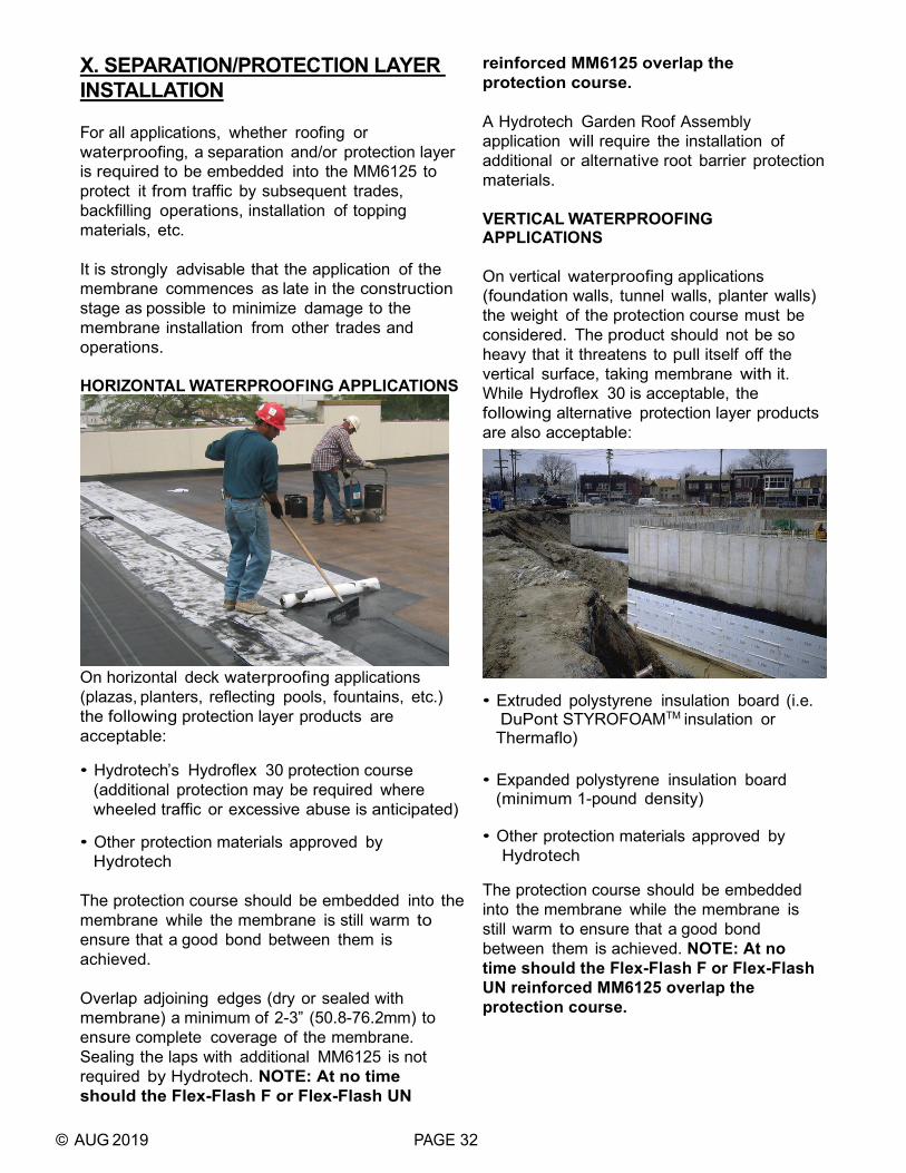
© AUG 2019 PAGE 32
X. SEPARATION/PROTECTION LAYER INSTALLATION For all applications, whether roofing or waterproofing, a separation and/or protection layer is required to be embedded into the MM6125 to protect it from traffic by subsequent trades, backfilling operations, installation of topping materials, etc. It is strongly advisable that the application of the membrane commences as late in the construction stage as possible to minimize damage to the membrane installation from other trades and operations. HORIZONTAL WATERPROOFING APPLICATIONS
On horizontal deck waterproofing applications (plazas, planters, reflecting pools, fountains, etc.) the following protection layer products are acceptable: • Hydrotech’s Hydroflex 30 protection course
(additional protection may be required where wheeled traffic or excessive abuse is anticipated)
• Other protection materials approved by
Hydrotech The protection course should be embedded into the membrane while the membrane is still warm to ensure that a good bond between them is achieved. Overlap adjoining edges (dry or sealed with membrane) a minimum of 2-3” (50.8-76.2mm) to ensure complete coverage of the membrane. Sealing the laps with additional MM6125 is not required by Hydrotech. NOTE: At no time should the Flex-Flash F or Flex-Flash UN
reinforced MM6125 overlap the protection course. A Hydrotech Garden Roof Assembly application will require the installation of additional or alternative root barrier protection materials. VERTICAL WATERPROOFING APPLICATIONS On vertical waterproofing applications (foundation walls, tunnel walls, planter walls) the weight of the protection course must be considered. The product should not be so heavy that it threatens to pull itself off the vertical surface, taking membrane with it. While Hydroflex 30 is acceptable, the following alternative protection layer products are also acceptable:
• Extruded polystyrene insulation board (i.e.
DuPont STYROFOAMTM insulation or Thermaflo)
• Expanded polystyrene insulation board (minimum 1-pound density)
• Other protection materials approved by Hydrotech
The protection course should be embedded into the membrane while the membrane is still warm to ensure that a good bond between them is achieved. NOTE: At no time should the Flex-Flash F or Flex-Flash UN reinforced MM6125 overlap the protection course.

© AUG 2019 PAGE 33
ROOFING APPLICATIONS For roofing applications, the following separation/protection layer products are acceptable: • Hydrotech’s Hydroflex 10
separation/protection sheet • Hydrotech’s Hydroflex 30 protection course • Hydrotech’s Hydrocap 90 or 160 cap sheet
(Hydrocap 90FR is required for FM approval)
• Hydrotech’s Hydroflex RBII heavy-duty root
barrier protection • Other protection materials approved by
Hydrotech The separation/protection layer should be embedded into the membrane while the membrane is still warm to ensure that a good bond between them is achieved. Overlap adjoining edges of Hydroflex 10 and 30 a minimum of 2-3” (50.8-76.2mm) to ensure complete coverage of the membrane. The laps may be left dry or sealed with MM6125. NOTE: At no time should the Flex-Flash F or Flex-Flash UN reinforced MM6125 overlap the protection course. In PMR applications, where insulation, filter fabric and ballast are installed above the roofing membrane and separation/protection layer, these topping materials must be installed as soon as possible. The separation/protection layer should not be left exposed more than 30 days if possible. In Hydrotech extensive Garden Roof Assemblies, Hydroflex 30 is followed by a loose laid layer of Root Stop. For intensive applications, Hydroflex RBII is to be used as the sole protection layer. In these instances, the Hydroflex RBII is installed in the same manner as Hydroflex 10 and 30, however, the laps must be sealed by propane torch or with MM6125 membrane. The lap/seam edges must then be coated with SpinOut root growth regulator. If the roof is to be insulated from below the deck or the structure cannot handle the weight of ballast materials, Hydrocap 160 may be used as the protection layer for the membrane as well as
the finished surface of the roof. In these instances, the Hydrocap is installed in the same manner as Hydroflex 10 and 30, however, the laps must be sealed with MM6125. When installation of a Factory Mutual Approved Class 1 Roof Cover is required, Hydrocap 90-FR is the required separation/protection layer prior to the installation of insulation and ballast. The immediate installation of Hydrocap into warm MM6125 is of even more importance than it is during the installation of Hydroflex 10 and 30.

© AUG 2019 PAGE 34
XI. MEMBRANE INTEGRITY TESTING Hydrotech recommends that prior to the installation of the topping materials, the membrane installation, or sections thereof, be water flood tested with 2” (50.8mm) of standing water for 48 hours. For sloped areas, soaker hoses and/or sprinklers can be used for water testing purposes. Alternatively, electric conductivity breach testing can be conducted. There are a number of testing firms that can provide this service in the U.S. SEE HYDROTECH TECH BULLETIN #5 “LEAK DETECTION OPTIONS”. Any leaks detected should be located, repaired and the area retested prior to the installation of overburden materials.
Electronic testing
Flood testing

© AUG 2019 PAGE 35
XII. REPAIR OF DAMAGED MEMBRANE DURING CONSTRUCTION MM6125 which has been damaged during construction can be easily repaired. The separation/protection layer should first be carefully removed, exposing not only the damaged area of membrane but also an area 6-12” (152.4-304.8mm) all around the damage. Heating the area with a hand-held torch will typically facilitate this. As the membrane below the separation/protection layer softens and melts, the layer can more easily be removed while still leaving membrane on the deck. Hot MM6125 can then simply be applied to the damaged area extending it out to the surrounding area over the existing MM6125. Since MM6125 is a thermoplastic material, the new (hot) material will soften and melt the existing material so that the two can melt together maintaining the monolithic membrane. If the damage was caused by another substance contaminating the MM6125, all contaminated material must be completely removed, and all traces of the contaminant eliminated prior to the repair being made. New separation/protection layer material must then be installed over the repair area. COMPLETED INSTALLATIONS In instances where the topping materials have already been installed, the membrane is still very easily repaired once the leak source is located and the topping materials are removed. The source of the leak should be easy to find since the MM6125 is typically bonded directly and fully to the substrate meaning that water is not free to travel between the membrane and the substrate. The same repair procedures as outlined above should be followed for repair of the membrane. USE OF COLD-APPLIED LIQUID MEMBRANES Hydrotech’s cold-applied Liquid Membrane 6090 or Monolithic Membrane 7800 may be used for repair of MM6125. Consult Hydrotech’s Technical Service Department.
XIII. REPAIR OF DAMAGED FLASHING In instances where the source of the leak or the damaged material is located through or on the flashing materials the following repair guidelines should be followed: FLEX-FLASH UN • The damaged flashing should first be
cleaned with soap and water, followed by a wiping with a solvent cleaner (white/unleaded gas).
• A patch should be cut from the same or
similar material (uncured neoprene) to be large enough to cover the damage and extend a minimum of 3” (76.2mm) beyond the damage in all directions.
• Hydrotech’s Splice Tape should be applied
to sides of the patch. SEE SECTION VII. “DETAILING -- FLEX-FLASH UN -- PROPER APPLICATION WITH ADHESIVES” PAGE 23.
• The patch should then be applied, without
stretching, and then rolled with a hand roller to ensure complete contact and to force any trapped air out from under.
FLEX-FLASH MB • The damaged flashing area should first be
cleared of any loose material and should be lightly torched to allow dust and dirt to be scraped or troweled away, leaving a relatively clean asphalt surface.
• A patch should be cut from similar material
(APP modified bitumen sheet) to be large enough to cover the damaged area and extend a minimum of 3” (76.2mm) beyond the damage in all directions.
• The asphalt should be torched in place such
that asphalt can be seen around the edges. SEE SECTION VII. “DETAILING -- FLEX-FLASH MB -- PROPER APPLICATION WITH TORCH” PAGE 24.
• If the flashing had been coated originally,
new coating should be applied to the patch.

© AUG 2019 PAGE 36
XIV. TOPPING MATERIALS Depending on the project design, any number of materials can be installed over the separation/ protection layer that has been embedded into the membrane. The following gives several examples of common topping materials that may be installed in various applications. VERTICAL WATERPROOFING
Vertical waterproofing applications (foundation, tunnel or planter walls) typically are covered with earth and/or gravel backfill directly against the protection layer. Adequate protection materials are essential to protect the membrane from possible damage from the backfilling operation. SEE SECTION X. “SEPARATION/PROTECTION LAYER INSTALLATION” FOR MORE INFORMATION”. DRAINAGE MAT (VERTICAL) Hydrotech’s Hydrodrain drainage products (Hydrodrain 400, 420, 700) can be used vertically below grade to move water to collection systems while at the same time reducing water head pressure from building up and threatening the integrity of the waterproofing and the structure itself. • Measure the height of the wall, adding
sufficient distance to overlap the perforated drain at the footing. Unroll the Hydrodrain and cut to length.
• At the top of the wall, peel back the fabric from
the core and cut off 4” (101.6mm) of the core. The drainage mat should be positioned such that the top of the core winds up 6-12” (152.4-304.8mm) below the surface of the backfill (grade).
• Glue the loose flap of fabric to the protection
layer or substrate with a common panel adhesive or wrap the fabric over and behind the core, securing mat with a termination bar.
• At the drain tile, peel the fabric from the
core and wrap it around the drain tile. Be sure that there is enough fabric to wrap all the way around the drain tile and still be able to be tucked back under the core which has been placed between the drain tile and footing.
• Backfill material should be placed as soon
as possible. INSULATION While not all projects will require the installation of an insulation board above vertical waterproofing, many will, especially if there are occupied spaces inside the structure. For vertical waterproofing applications, DuPont STYROFOAMTM, HI-60, HI-100 or Fan-Fold or Hydrotech’s Thermaflo products are typically installed. The insulation can be installed by adhering it to the protection layer with an appropriate adhesive or it can be installed directly into the MM6125 waterproofing (eliminating the separate protection layer). In this instance the panels will act as both the protection layer as well as the insulation (and in the case of Thermaflo, the drainage board also). SEE HYDROTECH’S THERMAFLO TECH DATA SHEET FOR SPECIFIC INSTALLATION INSTRUCTIONS FOR THIS PRODUCT. Backfill materials should be placed as soon as possible since extruded polystyrene insulation products are not UV stabilized.

© AUG 2019 PAGE 37
HORIZONTAL WATERPROOFING
Horizontal waterproofing applications (plaza decks, parking decks, etc.) can be covered with a variety of materials (earth, concrete, asphalt paving, insulated pavers assemblies, etc.). Adequate protection materials are essential to protect the membrane from possible damage from the installation of these materials. SEE SECTION X. “SEPARATION/PROTECTION LAYER INSTALLATION” FOR MORE INFORMATION”. Black or dark colored fabrics installed over the STYROFOAMTM should be avoided as elevated temperatures at the surface of the foam from the heat of the sun can cause distortion of the STYROFOAMTM. Hydrotech’s Hydrodrain AL and 300 and the PMR Stone Filter Fabric are white in color to prevent this condition. SEE HYDROTECH TECH BULLETIN #3, “PROTECTING STYROFOAMTM INSULATION FROM HIGH TEMPERATURES”. ASPHALT PAVING
Asphalt paving may be placed directly on top of the protection layer (Hydroflex 30 or other approved protection). Depending on the type of placement equipment to be utilized, additional protection or heavier duty protection may be required. The applicator should be on hand during placement to correct any damage. Asphalt paving can also be placed over Hydrodrain drainage mats
and DuPont STYROFOAMTM Insulation provided an appropriate sub-base (concrete, compacted stone) is installed prior to the placement of the asphalt pavement. Prior to the placement of the asphalt paving a water-based tack coat (SS-1) is typically applied to the clean, dry surface of the protection layer while ambient temperature is above 35°F (1.7°C). The paving should be installed in two lifts to a minimum thickness of 2 1/2” (63.5mm) with each lift being 1 1/4” (31.8mm) thick minimum and properly compacted. The paving overlay specifications (i.e. aggregates, grading and compaction requirements, waiting time before the paved surface is put into use) and acceptability of waterproofed surface for pavement application is strictly under the paving contractors or General Contractor’s responsibility and may be dictated by local codes. DRAINAGE MAT (HORIZONTAL)
Hydrotech’s Hydrodrain drainage products can be used horizontally to aid in the free movement of water to deck drains. • Clean the horizontal surface of loose debris
and unroll the Hydrodrain, fabric side up, in the direction of slope.
• Spot attach the Hydrodrain to the top of
the protection layer with duct tape or a panel adhesive that is compatible with all materials.
• Place adjacent panels so that the plastic
cores abut.
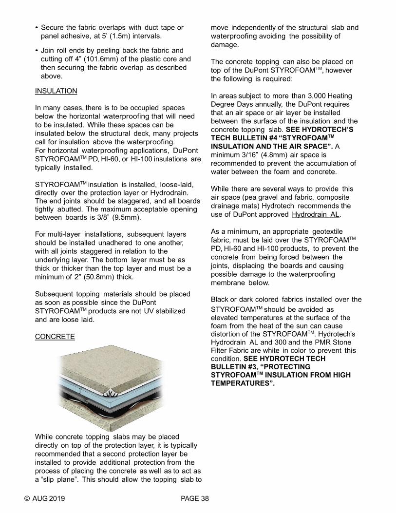
© AUG 2019 PAGE 38
• Secure the fabric overlaps with duct tape or panel adhesive, at 5’ (1.5m) intervals.
• Join roll ends by peeling back the fabric and
cutting off 4” (101.6mm) of the plastic core and then securing the fabric overlap as described above.
INSULATION In many cases, there is to be occupied spaces below the horizontal waterproofing that will need to be insulated. While these spaces can be insulated below the structural deck, many projects call for insulation above the waterproofing. For horizontal waterproofing applications, DuPont STYROFOAMTM PD, HI-60, or HI-100 insulations are typically installed. STYROFOAMTM insulation is installed, loose-laid, directly over the protection layer or Hydrodrain. The end joints should be staggered, and all boards tightly abutted. The maximum acceptable opening between boards is 3/8” (9.5mm). For multi-layer installations, subsequent layers should be installed unadhered to one another, with all joints staggered in relation to the underlying layer. The bottom layer must be as thick or thicker than the top layer and must be a minimum of 2” (50.8mm) thick. Subsequent topping materials should be placed as soon as possible since the DuPont STYROFOAMTM products are not UV stabilized and are loose laid. CONCRETE
While concrete topping slabs may be placed directly on top of the protection layer, it is typically recommended that a second protection layer be installed to provide additional protection from the process of placing the concrete as well as to act as a “slip plane”. This should allow the topping slab to
move independently of the structural slab and waterproofing avoiding the possibility of damage. The concrete topping can also be placed on top of the DuPont STYROFOAMTM, however the following is required: In areas subject to more than 3,000 Heating Degree Days annually, the DuPont requires that an air space or air layer be installed between the surface of the insulation and the concrete topping slab. SEE HYDROTECH’S TECH BULLETIN #4 “STYROFOAMTM INSULATION AND THE AIR SPACE”. A minimum 3/16” (4.8mm) air space is recommended to prevent the accumulation of water between the foam and concrete. While there are several ways to provide this air space (pea gravel and fabric, composite drainage mats) Hydrotech recommends the use of DuPont approved Hydrodrain AL. As a minimum, an appropriate geotextile fabric, must be laid over the STYROFOAMTM PD, HI-60 and HI-100 products, to prevent the concrete from being forced between the joints, displacing the boards and causing possible damage to the waterproofing membrane below. Black or dark colored fabrics installed over the STYROFOAMTM should be avoided as elevated temperatures at the surface of the foam from the heat of the sun can cause distortion of the STYROFOAMTM. Hydrotech’s Hydrodrain AL and 300 and the PMR Stone Filter Fabric are white in color to prevent this condition. SEE HYDROTECH TECH BULLETIN #3, “PROTECTING STYROFOAMTM INSULATION FROM HIGH TEMPERATURES”.

© AUG 2019 PAGE 39
SOIL/LANDSCAPING
Soil can be installed directly above the protection and/or root barrier or insulation layers. Care should be taken in the placement to eliminate any possible damage from workmen or equipment. If the soil is to be installed directly over the STYROFOAMTM insulation, an air space or air layer should be installed between the surface of the insulation and the soil. SEE HYDROTECH’S TECH BULLETIN #4 “STYROFOAMTM INSULATION AND THE AIR SPACE”. PAVERS
Concrete pavers can be installed directly on top of the protection layer or insulation. Pavers are typically installed on setting beds of sand, mortar or bituminous paving or with pedestals. If a sand setting bed is to be used directly over the insulation, an appropriate geotextile filter fabric should be laid over the STYROFOAMTM. Due to the heat involved, the use of bituminous setting beds, directly over STYROFOAMTM insulation, is prohibited. An appropriate air layer must be installed between any other setting bed and the insulation.
The use of pedestals provides the air space required and while no filter fabric is required, it may be requested to eliminate the color of the insulation showing through the paver joints. Hydrotech supplied, architecturally finished Architectural Pavers are typically installed in a loose-laid, open-joint assembly with a variety of pedestal supports and pedestals. ROOFING
In roofing applications, MM6125 is incorporated in what is typically referred to as a PMR, where the insulation layer is installed above the membrane, in lieu of below as in a conventional roof assembly. Adequate protection materials are essential to protect the membrane from possible damage from the installation of the insulation and ballast and to keep the insulation from sticking directly into the membrane. SEE SECTION X. “SEPARATION/ PROTECTION LAYER INSTALLATION” FOR MORE INFORMATION”. DRAINAGE MAT Hydrotech’s Hydrodrain drainage products can be installed directly on top of the separation/protection layer to promote the free drainage of water to the roof deck drains. SEE THE PRECEDING SECTION UNDER “HORIZONTAL WATERPROOFING - DRAINAGE MAT” FOR ADDITIONAL INSTALLATION INSTRUCTIONS. INSULATION As in waterproofing applications, Hydrotech promotes the use of DuPont’s STYROFOAMTM brand insulation for use over

© AUG 2019 PAGE 40
MM6125 in PMR / IRMAs. STYROFOAMTM, being an extruded polystyrene, exhibits excellent thermal properties, as well as water and freeze resistance. For roofing applications, STYROFOAMTM RoofMate (RM), Ribbed RM or PlazaMate (PD) are typically installed. The insulation is installed unattached directly over the separation/protection layer or drain mat, followed by a stone filter fabric sheet and stone ballast. The Ribbed RM product can be used when concrete pavers are installed as the ballast in lieu of stone. In these instances, the filter fabric is not required, but may be desirable, and the ribs in the surface of the insulation provide the required air space. The insulation must be installed in strict accordance with the DuPont’s installation requirements. The following is summarized from DuPont’s requirements. The following should be verified with Hydrotech and/or Dupont to ensure it is current information. The STYROFOAMTM insulation should be placed directly on top of the separation/protection layer or drainage mat with the channel side down. The end joints are to be staggered and all boards tightly abutted. The maximum acceptable opening between boards is 3/8” (9.5mm). The foam should be installed to within 3/4” (19.1mm) of all projections, penetrations, etc. For multilayer installations, subsequent layers should be placed unadhered over the first layer. Stagger all the joints in relation to the underlying layer. The bottom layer must be as thick as or thicker than the top layer and must be a minimum of 2” (50.8mm) thick. Install an acceptable filter fabric, unadhered, directly over the foam. All edges and ends are to be overlapped a minimum of 1’ (0.3m). No laps are to be installed within 6’ (1.8m) of the perimeter. The fabric should extend 2 - 3” (50.8-76.2mm) above the ballast at all perimeters and penetrations. BALLAST (LOOSE STONE AND/OR PAVERS) SEE DUPONT TECH SOLUTONS 508.1 BALLAST DESIGN GUIDE FOR PMR SYSTEMS FOR SPECIFIC BALLAST DESIGN BASED ON ROOF HEIGHT, PARAPET HEIGHT, BUILDING LOCATION AND DESIGN WIND SPEED. CONTACT THE HYDROTECH TECHNICAL
SERVICES OR GARDEN ROOF DEPARTMENTS FOR SPECIFIC BALLAST DESIGN REQUIREMENTS FOR GARDEN ROOF ASSEMBLIES. Black or dark colored fabrics installed over the STYROFOAMTM should be avoided as elevated temperatures at the surface of the foam from the heat of the sun can cause distortion of the STYROFOAMTM. Hydrotech’s PMR Stone Filter Fabric is white in color to prevent this condition. SEE HYDROTECH TECH BULLETIN #3, “PROTECTING STYROFOAMTM INSULATION FROM HIGH TEMPERATURES”. Minimum ballast requires that loose stone ballast, conforming to ASTM D-448 gradations 2, 4 or 5, be placed at a minimum of 10 lb/sqft (48.8kg/m2) in the field regardless of the foam thickness. Spread ballast evenly to ensure complete coverage of the filter fabric. 20 lb/sqft (97.6kg/m2) is typically required to be placed over a 8.5’ (1.2m) wide area around the perimeter and at all penetrations and drains. A row of concrete pavers can be substituted for the extra ballast weight in these areas. Pavers are also recommended in high foot traffic areas, near roof access areas and leading to and around all rooftop equipment. REFER TO TECH SOLUTIONS 508.2 FOR PROJECT SPECIFIC BALLASTING REQUIREMENTS. Pavers can be installed over larger areas of the deck or the entire deck to provide usefulness to the roof or additional wind resistance. When the pavered portion of the deck comprises 10% or less of the total deck area, the pavers can be installed directly on the foam. If the pavers comprise more than 10% of the total deck area, an air space must be incorporated between the surface of the foam and the bottom of the pavers. This can be accomplished by using STYROFOAMTM Ribbed RM insulation, a gravel separation layer, paver pedestals or Hydrodrain AL. SEE HYDROTECH TECH BULLETIN #4, “STYROFOAMTM INSULATION AND THE AIR SPACE”. CONCRETE Concrete topping slabs are often incorporated in the roofing design. SEE “HORIZONTAL

© AUG 2019 PAGE 41
WATERPROOFING - CONCRETE” ABOVE FOR ADDITIONAL INFORMATION. GARDEN ROOF COMPONENTS AND SOIL / VEGETATION The Garden Roof components required are typically loose laid and will be dictated by the type of green roof specified. SEE HYDROTECH’S GARDEN ROOF PLANNING GUIDE FOR SPECIFIC INSTALLATION INSTRUCTIONS. CONTACT THE HYDROTECH TECHNICAL SERVICES OR GARDEN ROOF DEPARTMENTS FOR SPECIFIC BALLAST DESIGN REQUIREMENTS FOR GARDEN ROOF ASSEMBLIES.

© AUG 2019 PAGE 42
XV. DO NOT APPLY MEMBRANE
• To concrete of density less than 90 pcf withoutfirst consulting with Hydrotech’s TechnicalServices Department.
• To “green” or uncured concrete surfaces.
• To surfaces contaminated with dirt, dust, oil,grease or laitance.
• To concrete holding enough moisture to causeblistering or pinholing of the membrane.
• Over concrete curing compounds, form releaseagents or surface coatings that are not approvedby Hydrotech.
• To concrete surfaces that have not beenproperly prepared, cleaned, and treated withSurface Conditioner.
• To surfaces with ridges, swirls, etc. high enoughto prevent application of a monolithic coatingwith membrane.
• Over smooth, steel-troweled concrete surfaces.
• If the membrane has been overheated – beyond400°F.
• At less than the minimum thickness prescribedby Hydrotech.
This information is intended only for general conceptual purposes. It is based on data and knowledge considered to be true and correct. It is offered for the user’s consideration, investigation and verification and is not intended to substitute for the advice provided by appropriate professionals. Hydrotech assumes no liability for the use of this information. The determination of the suitability and applicability of this information is the sole responsibility of the user.
2019-INS-3-MM6125-DY