Embed Size (px)
Citation preview

Modular Electric HMR Linear DrivesAssembly and Operating Instructions
2
Modular Electric HMR Linear Drives
WarrantyThese operating instructions are subject to changes including changes in technical details with respect to the information and figures contained herein.Parker-Hannifin GmbH grants no quality or durability guarantees nor any guarantees as to the suitability for specific purposes. Such guarantees must be expressly agreed upon in writing.Public statements, recommendations or advertising do not in any way represent quality specifications.The operator's warranty rights require that the operator immediately report any defects and precisely describe said defects in the complaint. Parker-Hannifin GmbH is not responsible under any circumstances for damage to the product itself or any consequential damage caused by the product resulting from improper handling of the product. If Parker-Hannifin GmbH is responsible for a defect, Parker-Hannifin GmbH shall be authorized, at its discretion, to undertake improvements or deliver replacements.In compliance with ISO 9000, all HMR products are equipped with a type plate that is connected to an HMR unit. The type plate must not be removed or damaged under any circumstances.Parker-Hannifin GmbH shall not be held liable, regardless of any legal basis, except for cases of intent or gross negligence; injuries to life, body or health; or defects of malicious nondisclosure or whose absence was expressly guaranteed in writing. Furthermore, if there is compulsory liability under the Product Liability legislation for personal injury and property damage to privately used objects, in the event of negligent breach of significant contractual obligations, Parker-Hannifin GmbH shall also be liable for cases of ordinary negligence; however, this is limited to damages that are contractually typical and foreseeable.Further claims are hereby excluded.Failure to adhere to these operating instructions or the relevant statutory provisions as well as any other information from the supplier shall invalidate the warranty.In particular, we are not responsible for failures caused by modifications made by the customer or other parties. In such cases, the normal repair costs will be calculated. These costs will likewise be calculated for a check of the unit if no fault can be determined on the unit.This regulation also applies during the warranty period.No claims exist as to the availability of previous versions or to the retrofitting capacity of the units delivered to adapt them to the respectively current model version.
CopyrightThe copyright to these operating instructions shall remain with Parker-Hannifin GmbH. Copyright 2014©.These operating instructions may not be reproduced or copied, either in full or in part, utilized for the purposes of competition without authorization, or distributed to third parties. Noncompliance could have legal consequences.
Product MonitoringOur goal is to provide safe, state-of-the-art products. Therefore, we monitor our products on a continuous basis, even after delivery. Please notify us immediately of any recurring malfunctions or problems with the HMR.
Language of the Operating InstructionsFor our international customers, these assembly and operating instructions are translated into various languages. The German version is the original. Other languages are a translation of the original operating instructions.
This operating manual is the translation of the original German version. Responsible: Dr.Axel Froeschle, R&D dept.

3
EN
Contents
1 Foreword to the Operating Instructions 4
2 Safety 4
3 Product Information 53.1 Scope of Application 53.2 Type Plate 5
4 Application, Proper Use 64.1 Prerequisite for Product Usage 64.2 Conversions and Modifications 64.3 Spare Parts and Accessories 6
5 Transportation and Storage 75.1 Transportation 75.2 Storage 7
6 Brief Description and Function 86.1 General 86.2 Setup and Mode of Action 86.3 Profile versions and Carrier 86.4 Profile versions 116.5 Guide System 116.6 Carriage 116.7 Noise Emission 11
7 Assembly 127.1 Important Information 127.2 Installation of Linear Drive 137.3 Attaching the Payload 167.4 Cover for IP54 177.5 Position Detection with Magnetic Switches 217.6 Impact Protection 257.7 Motor and Gearbox Mounting 26
8 Commissioning 308.1 First Commissioning 308.2 Operation 30
9 Maintenance and Repair 319.1 Customer Service 319.2 General Cleaning 319.3 Lubrication Intervals 319.4 Checking the Play of the Guide System 329.5 Checking the Bearing Play 329.6 Checking the Play in the Ball Screw Drive and Nut 329.7 Check and adjust belt tensioning 339.8 Checking the Cover Function 349.9 Replacing the Carriage 359.10 Replacing the Carriage 39
10 Decommissioning 4410.1 Disassembly of a Machine or System 4410.2 Disposal 44
11 Retrofit Kits 4511.1 IP54 Cover 4511.2 Position Detection internal and external 46
12 Spare Part / Wearing Part Kits 4712.1 Outer Band Package 4712.2 Outer Band 4712.3 Drive Type Ball Screw 4812.4 Carriage Belt Drive 4912.5 Carriage Ball Screw Drive 5012.6 Carriage Belt Drive 5112.7 Drive Shafts Belt 5212.8 Belt Tensioning Block 5312.9 Impact protection 54
13 Declaration of Incorporation 55
Section Page

4
Modular Electric HMR Linear Drives
1 Foreword to the Operating Instructions
The operating instructions contain important information and assist in preventing hazards, repair costs and downtimes; they also increase the reliability and service life of the HMR.Everyone that works with the HMR must read and adhere to the operating instructions, e.g.:• Operation, including setup, fault elimination in the work sequence, handling and disposal of hazardous substances
(operating materials and auxiliary materials)• Maintenance (cleaning, maintenance, inspection, repair)The information in these operating instructions, particularly the safety section, must be observed.
2 Safety
In addition to the operating instructions and the regulations regarding accident prevention and environmental protection that are applicable and mandatory in the country of use and at the site of use, the recognized technical regulations for safe and professional working must also be observed.
Explanation of symbols and notes ► This symbol is used as a handling prompt.
The symbol describes assembly steps, for example.Notes that are identified with the following symbols assist in preventing risks to life and limb. Distribute this information to all users.
Example of Symbols Explanation
DANGERWarns of personal injury that already exists at the moment of the warning
WARNINGWarns of personal injury if there is improper
handling or failure to comply with instructions
CAUTIONWarns of potential personal injury of which workers should be aware
ATTENTIONWarns of property damage
or malfunctions.
NOTE
Warns of potential worsening of results and/or provides tips.
Operator’s obligationThe following are the obligations of the operator:• Adherence to Machinery Directive 2006/42/EC. • Adherence to the valid, national regulations on occupational safety.• Proper use of the HMR.• Adherence to the regulations in these operating instructions.
OperatorsOperators for the overall system must ensure that the HMR is only operated by authorized and qualified personnel. Authorized personnel include trained specialists from the operator, from the manufacturer (Parker-Hannifin GmbH) and from an approved service partner.
Working in a safety-conscious mannerCheck at reasonable intervals that personnel are working in a safety-conscious manner and adhering to the operating instructions.

5
EN
3 Product Information
Designs
Ball screw drive Belt drive Linear motor
3.1 Scope of ApplicationThe description in these operating instructions relates to the products.
3.1.1 Ball Screw DriveLinear drive with ball screw drive and parallel guide HMRS08HMRS11HMRS15HMRS18HMRS24
3.1.2 Belt DriveLinear drive with toothed belt and parallel guide HMRB08HMRB11HMRB15HMRB18HMRB24
3.2 Type PlateThe type plate is located on the HMR end cap drive end. A second plate has been enclosed.
Customer order number
Customer
Production orderSerial order number
Calendar week of productionProduct key

6
Modular Electric HMR Linear Drives
4 Application, Proper Use
The operational safety of the HMR is only ensured with proper use.Proper use of the HMR only includes the following:• Moving loads• Positioning masses• Exerting forceThe HMR is driven with rotating or linear motors.The catalog data and the conditions specified in the order confirmation must be taken into account. Please note the limits from the technical data and the corresponding characteristic curves as per the catalog information.The values apply to continuous operation. With intermittent operation, the combination of speed and load may accommodate higher values for short periods. However, the individual maximum values indicated must not be exceeded.If the HMR is used in any other manner, this does not constitute proper use.Obvious misuse Any use to transport persons or applications of any manner in the private sector (consumers) is not authorized. This may result in personal injury and damage to property. We shall accept no liability for any injury or damage resulting herefrom. The user shall bear sole responsibility and risk.
The following are not authorized:• Unauthorized modifications to the HMR• Processes that affect the safety of the HMR
Note all of the information attached to the HMR.Keep this information in a fully legible condition.In addition, note the manufacturer’s information regarding lubricants, solvents and cleaning agents.
4.1 Prerequisite for Product UsageThe installation must always be carried out such that:• The HMR is installed without delay• All connections and control components are accessible • The type plate with the product name remains legible• The ambient conditions are maintained corresponding to design delivered (IP20 or IP54)The operator must secure any hazardous sources that may result during installation in machines and systems between Parker-Hannifin products and customer equipment, according to CE conformity.
4.2 Conversions and ModificationsHMR linear drives may not be modified with respect to the design or safety-related features without the written approval of Parker-Hannifin GmbH. Any unauthorized modification in this respect will exclude any liability on the part of Parker-Hannifin GmbH.If special attachments are to be used, the assembly regulations of the manufacturer must be observed.The following also apply:• Relevant accident prevention regulations• Generally recognized safety rules• EU directives• Country-specific provisions.
4.3 Spare Parts and AccessoriesOriginal spare parts and accessories authorized by the manufacturer are intended to protect your safety. The use of other parts could change the properties of the HMR.We shall accept no liability for any resulting consequences.

7
EN
5 Transportation and Storage
5.1 TransportationThe electric HMR linear drives are extremely precise products. Impacts could damage the mechanical system of the drive, resulting in a negative influence on functionality. To prevent damage during transportation, place the units in appropriate protective packaging.
WARNINGLifted or suspended loads can tip over
or crash down.This could result in severe injuries or damage to property.
► Never walk under suspended loads. ► Transport loads as close to the floor as possible. ► Securely fasten the load for transportation and note the center of gravity.
CAUTIONHeavy parts can slip during handling!
This could result in severe injuries or damage to property. ► Hold parts or units securely. ► Wear safety gloves. ► Use tools and supports.
ATTENTIONThe profile may bend or snap!
► Support the drive profile appropriately during transportation and handling (e.g. with a bar).
Transport packed or unpacked HMR units using a crane or forklift• In storage and handling static deflection of the actuator should not exceed
0.1% of total length.• Larger deformations could result in a reduced service life, increased wear,
and increased friction. These must therefore be avoided!• Attach ropes as shown/use fork as shown.
NOTE
Notify the shipping company and Parker-Hannifin GmbH or the delivery company immediately, in writing, of any transportation damage or missing parts.
5.2 StorageThe storage location must be:• Dry, free of dust and vibrations• On a flat surface.
Deflection of the HMR must be avoided!• Support the drive profile appropriately during transportation and handling.

8
Modular Electric HMR Linear Drives
M
K
LB L
R
NB NC
N
NA
MC
MB
MA
“Basic” profile
T-slot mounting
Dimension table – Profile versionsSeries K LB LR M MA MB MC N NA NB NCHMRx08 85 60.0 71.0 50 5.2 4.5 2.5 4.5 3.4 3.0 2.5HMRx11 110 69.5 89.5 70 5.2 4.5 2.8 4.5 3.4 3.0 2.5HMRx15 150 90.0 114.0 96 6.2 6.8 3.0 6.5 5.2 4.6 3.5HMRx18 180 111.5 134.5 116 8.0 7.8 4.5 8.5 5.2 4.5 3.5HMRx24 240 125.0 153.0 161 10.0 10.2 5.3 8.5 5.2 4.5 3.5
“Reinforced” profile
Dimensions in mm
6 Brief Description and Function
6.1 GeneralThe HMR catalog contains extensive information on the following:• Dimensions, space requirements• Load-carrying capacity, forces and torques• Weights and further technical dataThe electric linear drives from the HMR series may only be operated within the permissible specifications. We reserve the right to make technical changes.
6.2 Setup and Mode of ActionThe electric HMR linear drives are used for the linear moving and positioning of an external payload. A combination of multiple linear drives allows the spatially oriented movements to be achieved. When the linear drive and the payload are in motion, a force is exerted in the direction of movement.• A payload is fastened at the pre-existing threaded holes on the carriage. • The carriage is connected to a Drive Type (screw, toothed belt) and is moved by this Drive Type.• The carriage is mounted on a linear guide system in a movable manner; the linear guide system is fastened to the
profile version. • The profile version is fastened directly onto a substructure. • The “reinforced” profile can also be used as a self-supporting structure. In doing so, attention must be paid to the
permissible loads.• A cover can be constructed on the linear drive to reduce the penetration and discharge of dirt or abrasion. • Lubrication can be carried out during service as needed via external lubricating nipples. • A position signal can occur through magnetic switches mounted on the inside or outside, which are switched by a
magnetic package on the carriage. • A displacement signal of the linearly moving carriage can be achieved by means of an installed displacement
measuring system.
6.3 Profile versions and CarrierA carriage is moved and force exerted through a rotational movement at the drive shaft.• Temperature range: -20°C to +80°C• Installation position: Any• Humidity: Non-condensing.
Dimensions

9
EN
6.3.1 HMRS Ball Screw DriveA carriage is linearly moved by a rotating ball screw drive driven by the motor; the carriage is mounted on a guide system in a movable manner. The screw turns clockwise. The load to be moved is fastened onto the carriage. The permissible thrust force, speed and the linear displacement per rotation of the drive shaft depends on the design of the screw used.
The dimensioning is as per the ordering process (HMR catalogue) • ES = Effective Stroke• SS = Safety Stroke• CD = Carriage distance• CLS = Carriage length Standard • CLL = Carriage length long• S = Stroke• 0S = Order Stroke• OAL = Over All Length
X
Q
CL / CLS L
Q
XStroke S = Order Stroke OS
Over All Length OAL
Order Stroke OS = Effective Stroke ES + 2 x Safety Stroke SSOver All Length OAL = Order Stroke OS + Carrier Length CL + 2 x dimension end cap X
Standard design with one carriage
CL / CLS L
Q
X CL / CLS L
Q
X
Over All Length OAL
Order Stroke OS = Effective Stroke ES + 2 x Safety Stroke SS + Carriage distance CDOver All Length OAL = Order Stroke OS + 2 x Carrier Length CL + 2 x dimension end cap X
Tandem design with two carriages
Stroke S = Order Stroke OS
Dimension table - Carriage and Over All Length HMRSProduct size CLS CLL Q XHMRS08 195
in advance
16 54.0HMRS11 225 20 65.0HMRS15 266 20 62.0HMRS18 311 20 66.0HMRS24 371 20 73.0
Dimensions in mm

10
Modular Electric HMR Linear Drives
Dimension table - Carrier and Over All Length HMRBProduct size CLS CLL Q XHMRB08 195
in advance
16 74HMRB11 225 20 85HMRB15 266 20 110HMRB18 311 20 120HMRB24 371 20 140
Dimensions in mm
6.3.2 HMRB Belt DriveA carriage is linearly moved by a toothed belt driven by the motor; the carriage is mounted on a guide system in a movable manner. The load to be moved is fastened onto the carriage. The permissible thrust force, speed and the lead constant per rotation of the drive shaft depends on the design and on the toothed belt used.
The dimensioning is as per the ordering process (HMR catalogue) • ES = Effective Stroke• SS = Safety Stroke• CD = Carriage distance• CLS = Carriage length Standard • CLL = Carriage length long• S = Stroke• 0S = Order Stroke• OAL = Over All Length
Q
X
Q
XCL / CLS L Stroke S = Order Stroke OSOver All Length OAL
Order Stroke OS = Effective Stroke ES + 2 x Safety Stroke SSOver All Length OAL = Order Stroke OS + Carrier Length CL + 2 x dimension end cap X
Option Carrier Standard
Option Carrier Tandem
Q
X CL / CLS L
Q
XCL / CLS L
Over All Length OAL
Order Stroke OS = Effective Stroke ES + 2 x Safety Stroke SS + Carriage distance CDOver All Length OAL = Order Stroke OS + 2 x Carrier Length CL + 2 x dimension end cap X
Q
X
Q
X CL / CLS L CL / CLS LOrder Stroke OS
Stroke S Stroke S
Over All Length OAL
Order Stroke OS = 2 x Stroke S = 2 x Effective Stroke ES + 4 x Safety Stroke SS + Carriage distance CDOver All Length OAL = Order Stroke OS + 2 x Carrier Length CL + 2 x dimension end cap X
Option Carrier Bi-part for opposite movements
11
EN
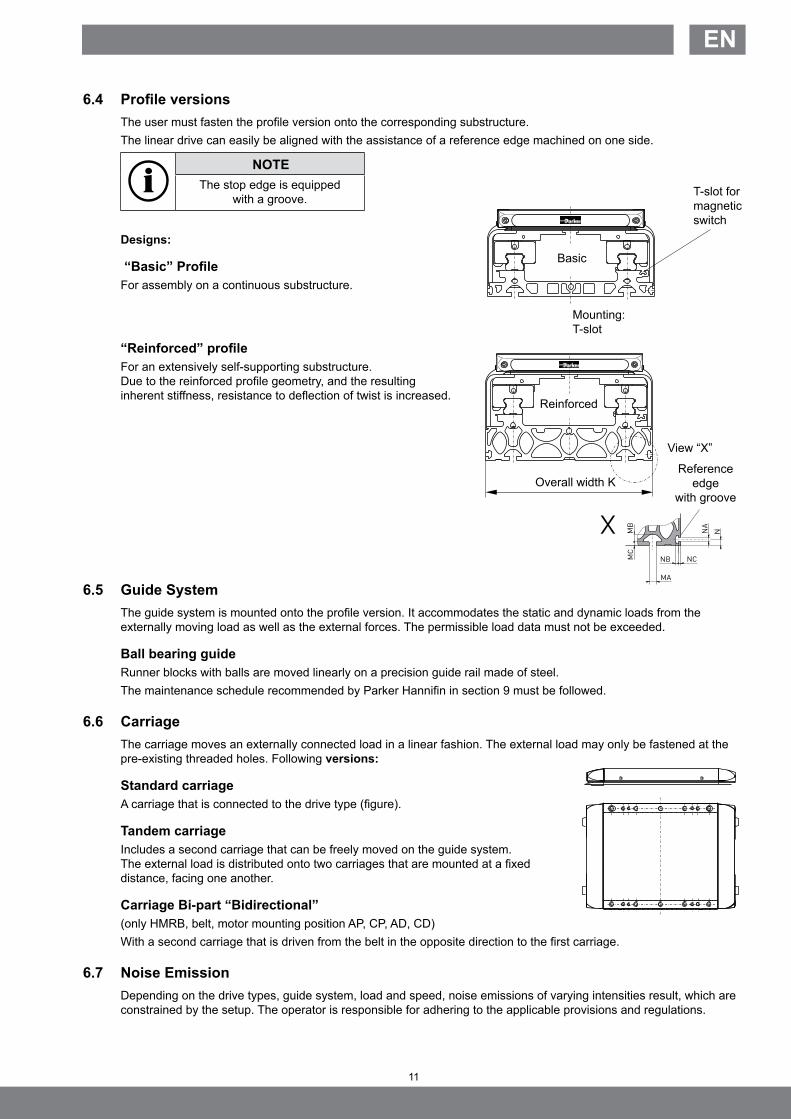
6.4 Profile versionsThe user must fasten the profile version onto the corresponding substructure. The linear drive can easily be aligned with the assistance of a reference edge machined on one side.
NOTEThe stop edge is equipped
with a groove.
Designs:
“Basic” ProfileFor assembly on a continuous substructure.
“Reinforced” profileFor an extensively self-supporting substructure. Due to the reinforced profile geometry, and the resulting inherent stiffness, resistance to deflection of twist is increased.
6.5 Guide SystemThe guide system is mounted onto the profile version. It accommodates the static and dynamic loads from the externally moving load as well as the external forces. The permissible load data must not be exceeded.
Ball bearing guideRunner blocks with balls are moved linearly on a precision guide rail made of steel. The maintenance schedule recommended by Parker Hannifin in section 9 must be followed.
6.6 CarriageThe carriage moves an externally connected load in a linear fashion. The external load may only be fastened at the pre-existing threaded holes. Following versions:
Standard carriageA carriage that is connected to the drive type (figure).
Tandem carriage Includes a second carriage that can be freely moved on the guide system. The external load is distributed onto two carriages that are mounted at a fixed distance, facing one another.
Carriage Bi-part “Bidirectional” (only HMRB, belt, motor mounting position AP, CP, AD, CD)With a second carriage that is driven from the belt in the opposite direction to the first carriage.
6.7 Noise EmissionDepending on the drive types, guide system, load and speed, noise emissions of varying intensities result, which are constrained by the setup. The operator is responsible for adhering to the applicable provisions and regulations.
T-slot for magnetic switch
Reference edge
with groove
Mounting: T-slot
Basic
Reinforced
Overall width K
MC
MB
MA
NB NC
NNA
View “X”

12
Modular Electric HMR Linear Drives
7 Assembly
7.1 Important InformationHMR installation, and all other installations, may only be carried out by trained mechanical technicians or electricians. The information in these instructions must be strictly observed.
Tightening torques for screws
Thread Tightening torque ToleranceM3 1.2 Nm ± 0.2 Nm
M4 3 Nm ± 0.5 Nm
M5 5.5 Nm ± 0.8 Nm
M6 10 Nm ± 1.5 Nm
M8 20 Nm ± 3 Nm
M10 40 Nm ± 6 Nm
Remarks regarding use and operation:
ATTENTIONExcessive forces or loads
Overload of the HMR would be possible
► Adhere to catalog data.
Mechanical Additional drill holes or other machining may not be implemented on the HMR!
► Only attach the payload at the threaded holes on the carriage in section 7.3. ► Adhere to the permissible load limits such as weight, speed and acceleration. ► Adhere to the permissible load limits such as weight, speed and acceleration.
Electrical information ► The controller, motor, position detection and all other necessary electrical elements
must be connected according to technical rules, within the responsibility of the operator. ► Do not place magnetic switches in the vicinity of ferritic parts or moving loads. ► Only use the seating grooves and/or the mounting holes on the aluminium profile for the
assembly and mounting of the profile version, as described in detail in the HMR catalog.
Fz
Fy
Mz
My
Mx
Combined loadsThe maximum permissible load for linear drives subject to simultaneous multiple loads, forces and bending moments are calculated using the formula below. Maximum permissible loads must not be exceeded.
Take note of the additional information in the Parker HMR catalogue on the “Maximum permissible load” on page 7.The sum of all loads must under no circumstance be > 1.
Fy Fz Mx My MzL = + + + + ≤ 1
Fy(max) Fz(max) Mx(max) My(max) Mz(max)

13
EN
7.2 Installation of Linear DriveAll installation measurements can be found under “6.3 Carrier profile and drive body” on page 8 and in the HMR catalogue.
► During assembly, the HMR must be sufficiently supported and securely placed in a machine/system.
ATTENTIONStraightness tolerance exceeded
The screw-on surface is important!
► Ensure evenness and straightness.
The maximum straightness and evenness in the running direction of the linear system can only be achieved if the corresponding mounting points or surfaces are within the required tolerance.The mounting surface for the profile version must have evenness of at least 0.2 mm/m at the clamping points.
NOTE ► Adhere to the tightening torques for screws according to section 7.1. on page 12.
7.2.1 Mounting with T-slots ► Use of T-slot profiles. Mounting from below.
Standard screws and sliding blocks or rails from the common profile systems can be used. Mounting parts such as sliding blocks are available as accessories.
► Please observe the required number of T-sliding blocks in accordance with the axial holding force for secure assembly (see table below and HMR catalogue page 38).
T-slot mounting
HMRB
T-slot mounting
HMRS
Dimension table - T-slot mounting HMR
Product size A B C Ø D M N Order no.HMRx08 8.0 4.0 11.5 M5 5.0 0.5 56351FILHMRx11 8.0 4.0 11.5 M5 5.0 0.5 56351FILHMRx15 10.5 6.4 22.5 M6 6.4 0.6 56351FILHMRx18 13.5 6.7 22.5 M8 8.5 1.0 56352FILHMRx24 16.5 8.9 28.5 M10 10.5 1.0 56353FIL
Max, axial holding force per mounting set
Product size
T-slot mounting
min, number of sets required per meter
[N] horizontal horiz, side over head vertical
HMRx08 1,000 4 11 19 5HMRx11 1,000 4 11 19 5HMRx15 1,600 4 5 10 5HMRx18 2,700 4 5 10 5HMRx24 3,200 4 4 8 5
14
Modular Electric HMR Linear Drives
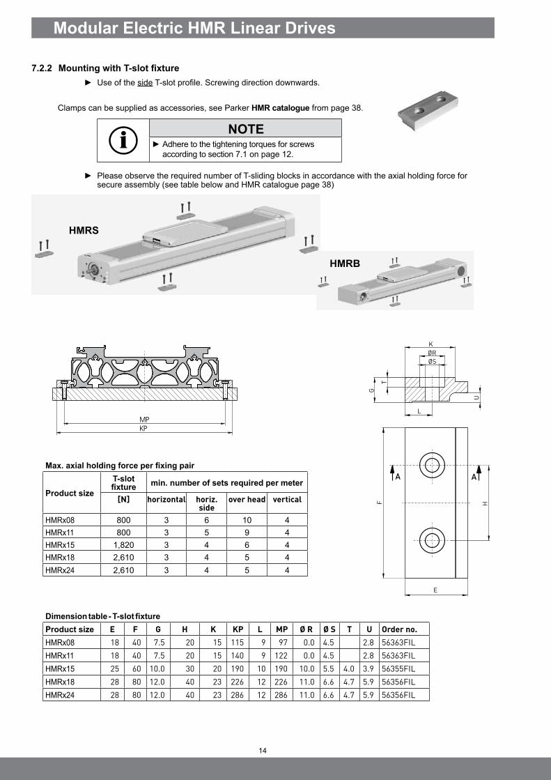
7.2.2 Mounting with T-slot fixture ► Use of the side T-slot profile. Screwing direction downwards.
Clamps can be supplied as accessories, see Parker HMR catalogue from page 38.
NOTE ► Adhere to the tightening torques for screws according to section 7.1 on page 12.
► Please observe the required number of T-sliding blocks in accordance with the axial holding force for secure assembly (see table below and HMR catalogue page 38)
HMRS
HMRB
MP
KP
Dimension table - T-slot fixture
Product size E F G H K KP L MP Ø R Ø S T U Order no.HMRx08 18 40 7.5 20 15 115 9 97 0.0 4.5 2.8 56363FILHMRx11 18 40 7.5 20 15 140 9 122 0.0 4.5 2.8 56363FILHMRx15 25 60 10.0 30 20 190 10 190 10.0 5.5 4.0 3.9 56355FILHMRx18 28 80 12.0 40 23 226 12 226 11.0 6.6 4.7 5.9 56356FILHMRx24 28 80 12.0 40 23 286 12 286 11.0 6.6 4.7 5.9 56356FIL
Max. axial holding force per fixing pair
Product size
T-slot fixture min. number of sets required per meter
[N] horizontal horiz. side
over head vertical
HMRx08 800 3 6 10 4HMRx11 800 3 5 9 4HMRx15 1,820 3 4 6 4HMRx18 2,610 3 4 5 4HMRx24 2,610 3 4 5 4

15
EN
7.2.3 Distance between supportsDistance between supports FY
Distance between supports Fz
Forc
e Fy
[N]
Forc
e Fz
[N]
permissible distance between supports [mm]
permissible Distance between supports [mm]

16
Modular Electric HMR Linear Drives
7.3 Attaching the PayloadThe user is responsible for the use of the HMR and makes decisions on the attachment of loads as well as the operating status with speed, acceleration and frequency of movements. The HMR may only be installed according to the catalog’s specifications.
WARNINGDanger due to fracture or deformation of components, incorrect arrangement of loads and crashing of loads
This could result in severe injuries and damage to property.
► Attach components according to technical rules. ► Move heavy parts with a hoist; wear safety gloves. ► Observe HMR catalog data with respect to arrangement.
There are various threaded holes on the carriage available to the user of the HMR for mounting the payload.
ATTENTIONRisk of damage to the carriage
Additional holes will weaken or damage important components and are not permitted.
► Do not drill or counter bore. ► Distribute load forces as required.
NOTE ► Adhere to the tightening torques for screws according to section 7.1 on page 12.
The carriage has two dowel holes into which dowel sleeves can be inserted. This makes it possible to repeat the disassembly/assembly of the payload without realignment.
Stop groove and centring for the adapter sleeve are on the
same drive side
* in advance
Centering/alignment of payload
Suitable dowel sleeves: (packing unit 4):
Type Item no.HMR-08 56455FIL
HMR-11 56455FIL
HMR-15 56455FIL
HMR-18 56457FIL
HMR-24 56459FIL
Dimension table - Carriage length Standard HMRS
Type RS RL T TAS TAL ta TBS TBL tb TCS TCL tc TDS TDL td TES TEL te TKH7 U U1HMRS08 128 -* 74 97 -* M4x12 70 -* M4x12 40 -* M4x12 - -* - - -* - 7 83 5,5
HMRS11 150 -* 96 122 -* M5x12 97 -* M5x12 65 -* M5x12 25 -* M5x12 - -* - 7 105 7,0
HMRS15 191 -* 120 170 -* M5x12 122 -* M5x12 - -* - 70 -* M5x12 - -* - 7 135 15,0
HMRS18 231 -* 150 202 -* M6x12 170 -* M5x10 122 -* M5x10 90 -* M6x12 - -* - 9 165 15,0
HMRS24 291 -* 192 262 -* M8x16 202 -* M6x12 170 -* M5x10 140 -* M8x16 122 -* M5x10 12 210 24,0

17
EN
7.4 Cover for IP54It is also possible to install various assemblies and equipment as a retrofit. When doing so, remove the cover as necessary.
Cover
Cover
Cover sheet
Inner strip guide
Carriage cover
A-coil with sealing band
A-band coating with sealing band
Holder cover
Holder cover
Clamping plate outer band
Outer band
Lateral wiper
Sealing band
Cover sheet
Inner strip guide
Carriage cover Clamping plate outer band
Outer band
Lateral wiper
Sealing band
HMRS
HMRB

18
Modular Electric HMR Linear Drives
For HMR installation, maintenance purposes or conversion:
7.4.1 IP54 Cover Disassembly
► Remove the clamping plate of the outer band on the end caps. ► Disassemble the carriage cover. ► Push the cover sheet out of the grooves. ► Remove the outer band.
Cover sheetCarriage cover
Clamping plate outer band
Outer band
► Detach the inner strip guide. ► Unscrew the lateral covers. ► Only HMR08, 11: Loosen the fastening screws with slot nuts and remove the cover ► Only HMR15, 18, 24: To loosen the covers, lever one end with a screwdriver from the inside.
Inner strip guide
Cover
► Pull the covers out of the retaining groove. ► Remove the lateral wipers.
Cover
Lateral wiper
HMRB
HMRB
HMRB
19
EN
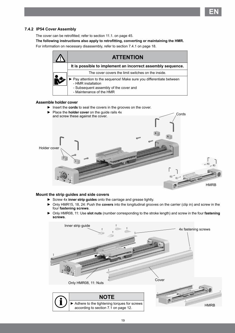
7.4.2 IP54 Cover AssemblyThe cover can be retrofitted; refer to section 11.1. on page 45.The following instructions also apply to retrofitting, converting or maintaining the HMR.For information on necessary disassembly, refer to section 7.4.1 on page 18.
ATTENTIONIt is possible to implement an incorrect assembly sequence.
The cover covers the limit switches on the inside.
► Pay attention to the sequence! Make sure you differentiate between - HMR installation - Subsequent assembly of the cover and - Maintenance of the HMR
Assemble holder cover ► Insert the cords to seal the covers in the grooves on the cover. ► Place the holder cover on the guide rails 4x
and screw these against the cover.
Mount the strip guides and side covers ► Screw 4x inner strip guides onto the carriage and grease lightly. ► Only HMR15, 18, 24: Push the covers into the longitudinal grooves on the carrier (clip in) and screw in the
four fastening screws. ► Only HMR08, 11: Use slot nuts (number corresponding to the stroke length) and screw in the four fastening
screws.
NOTE ► Adhere to the tightening torques for screws according to section 7.1 on page 12.
Cords
Inner strip guide
Cover
HMRB
HMRB
Holder cover
4x fastening screws
Only HMR08, 11: Nuts

20
Modular Electric HMR Linear Drives
Mount the wipers and outer band
► Insert the lateral wipers into the grooves on the carriage. Pay attention to the alignment (lips should be facing outward).
► Place both A-band coatings on the holder cover. With this the sealing strips are visible and are on the covers in each case.
► Place the outer band onto the center of the HMR.
ATTENTIONPremature wear of the Outer band
Twisted/distorted installation of the Outer band
► Careful tightening of the clamping strip - Outer band not twisted - Install without forming any ripples.
NOTE ► Adhere to the tightening torques for screws according to section 7.1 on page 12.
► On one side, tightly clamp the outer band with the clamping plate and screw on.
Mount cover sheet and cover
► Lightly grease the bottom of the carriage cover sheet. ► On one side, insert the cover sheet into the groove of the carriage. ► Only HMR08, 11: push the side cover from the front into the grooves of the carriage. ► Only HMR15, 18, 24: Lock the side cover into position by applying central pressure from above onto the
opposite side. Note the correct position of the sealing strip in the carriage groove. ► Align the carriage cover on the carriage and screw down tightly.
The outer band must have contact with the entire profile length without any ripples. ► Tightly clamp the outer band, without any tension, to the second clamping plate.
Lateral wiperOuter bandClamping plate
outer band
Clamping plate outer band
Cover sheet
Carriage cover
Outer band coating
Holder cover
HMRB
HMRB

21
EN
SSSSES
E- R E+
7.5 Position Detection with Magnetic Switches
ATTENTION
Potential damage to equipment!Missing or incorrect signals from the end position
switches in the controller.
► Essentially, clamp and set up end switches before commissioning!
7.5.1 Definition
End position switch The use of end position switches is highly recommended for operating electric linear drives to prevent mechanical damage in the end positions. End position switches must be implemented in the NC (normally closed) function so that any cable breaks can be detected by the controller.
Homing switch In addition to the end position switches, a homing switch can be used to assign a repeatable zero point to the linear system. Homing switches are normally implemented in the NO (normally open) function. In this process, the homing switch must be between the end position switches.
Switch types The magnetic switches described in the following can be used as switches. The switch function is triggered by the magnetic package mounted under the carriage. The user can use mechanical switches, proximity sensors etc. in the same manner.
Setting up switch points
The switch point for the end position switches must be selected on both sides of the linear drive so as to ensure braking of the payload up to a standstill (depending on the motor system used) within the safety distance and at any time during operation. Depending on the application, the homing switch can be set up anywhere between the end position switches. If the switch points are not indicated when ordering, the user must carry out the alignment as well as the connection of the magnetic switches.
NOTEEssentially, the user is responsible for checking each linear drive for proper setup and the function of the magnetic switches.
Example: Product code with digit in bold which displays the position of the safety distance HMRxxxx-xxxx-xxxx2xxxx => 2 = 20 mm safety distance.
SS = Safety StrokeES = Effective Stroke
Verfahrweg
E- R E+
SS SSES

22
Modular Electric HMR Linear Drives
HMRS
HMRB
7.5.2 Magnetic Switch Types
7.5.3 Connection Assignment for M8 ConnectorThe connector assignment complies with DIN EN 50044
3-pin connector assignment
7.5.4 Installation of terminal block and M8 connectorsThe IP54 cover must be opened as per section 7.4.1.
Mounting the M8 connectors in the end cap
End switch E+
End switch E-
Homing switch R
Nut
Nut Connector plate
M8 connector
M8 connector
PlugEnd switch E+
End switch E-
Homing switch R
► Remove the plugs from the end cap. ► Insert the M8 connectors through the hole,
starting from the back of the end cap drive end side, and secure with nuts.
► Solder the respective wire ends (use the heat shrink tubing).
► Remove the connector plate and corresponding plugs. ► Fasten the M8 connector to the connector plate with
the nuts. ► Pass the cable through clearance. ► Fasten connector plate.
brown (bn)black (sw)
blue (bl)
brown (bn)
blue (bl)
PIN assignment (top view)
Electrical connection: cable type RST-K
������������
�����
��
��
�
�
�
��
Reed 2-pole
Closing function (normally open)
Opening function (normally closed)
PNP 3-poleClosing function (normally open)
Electrical connection: cable type EST-K
Electrical connection: plug type RST-SReed 2-pole
Typ EST-S
PNP 3-pole
brown (bn)
blue (bl)
brown (bn)
blue (bl)
brown (bn)black (sw)
blue (bl)

23
EN
7.5.5 Setting up the Internal Magnetic SwitchesThe IP54 cover must be opened as per section 7.4.1 on page 18.
Tip: Adjust the carriage to the desired position (end position/homing) and then move the magnetic switch in the T-slot until the switch point is reached.
► Insert the magnetic switch into the T-slot, if not preassembled (or loosen it with a size 1.5 Allen key).
► Set up the switch point by moving the magnetic switch until the switch point is reached. ► Tightly clamp the magnetic switch with a size 1.5 Allen key.
Connecting the magnetic switches
ATTENTIONRisk of damage to cable!
Cable shearing and scuffing will cause failures and damage.
Route cable securely and tightly.
► Cut the magnetic switch cable to the desired length and strip it. ► Route the cable on the PCB according to the terminal assignment, see section 7.5.3 on page 22. ► Secure the loose cable in the T-slot with the cable holders.
► Connect the respective connection cable with the M8 mounted connectors on the cover. ► Insert the connection cable in the controller (refer to section 11.2 on page 46 for information on ordering
connection cables).
End switch E -Homing switch R
Magnet
Magnet switch
Profile nut with sensor cable
HMRB
End switch E +

24
Modular Electric HMR Linear Drives
7.5.6 Setting up the External Magnetic SwitchesOnly possible with the IP54 cover!
Retrofitting:All magnetic switches are mounted via a switch rail to be affixed onto the IP54 cover.
► Remove the strip from the IP54 cover.
Setting up the magnetic switches ► Insert the previously aligned magnetic switches into the switch rail (size 1.5 Allen key).
NOTEAdjust the carriage to the desired position (end position / homing) and then move the magnetic switch in the T-slot until the switch point is reached.
Adjusting the switch points (setup) ► Move the magnetic switches until the switch point is reached. ► Tightly clamp the magnetic switch with a size 1.5 Allen key.
Connecting the magnetic switches ► Connect the respective connection cable with the M8 connector for the magnetic switch. ► Secure the loose cable in the T-slot with the cable holders. ► Insert the connection cable in the controller
(refer to section 11.3 for information on ordering connection cables).
End switch E -
Homing switch RT-slot cable holder
Terminal profile switch groove
HMRB
End switch E +

25
EN
7.6 Impact ProtectionImpact protection reduces the risk of mechanical damage from an unbraked, unforeseeable impact in the end position. If the safety distance of the end positions is crossed by the carriage and payload, the shock absorbers compensate, in full or in part, for the residual energy. The shock absorbers are only intended to protect a foreseeable impact of the carriage in the mechanical end position and not for continuous operation. The permissible energy absorption is listed in the HMR catalog. If there is an overload, the impact protection must be replaced.The use of end position switches with the safety distance required for the application, as described in section 7.5.1, is not affected by this.The IP54 cover must be opened as per section 7.4.1 on page 18 when retrofitting or replacing the impact protection.
NOTE ► Adhere to the tightening torques for screws according to section 7.1. on page 12
Shock absorber
HMRB

26
Modular Electric HMR Linear Drives
7.7 Motor and Gearbox Mounting
Overview / exploded view of motor installation with a flange plate, using a toothed belt as an example.
Overview / exploded view of gearbox installation with two flange plates, using a spindle drive as an example.
Motor coupling
Motor flangeCoupling housing
Motor
Drive shaft
Gearbox
Motor coupling
Motor flange
Coupling housing
Motor
NOTEThe motor flange usually consists of one flange plate. If the geometric requirements are unfavorable in the assembly, the motor flange can consist of two flange plates. The motor flange designation always remains the same and does not depend on whether a motor or a gearbox with motor is to be installed on the linear drive.
27
EN
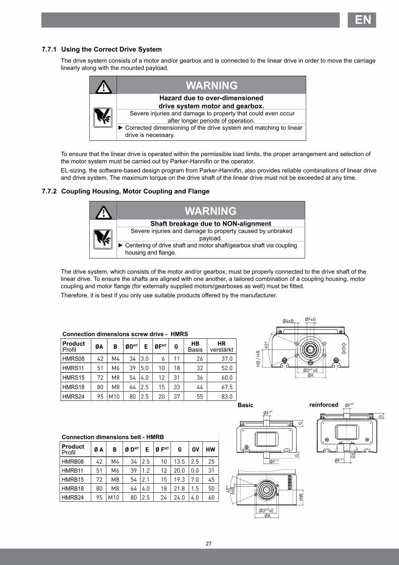
7.7.1 Using the Correct Drive SystemThe drive system consists of a motor and/or gearbox and is connected to the linear drive in order to move the carriage linearly along with the mounted payload.
WARNINGHazard due to over-dimensioned drive system motor and gearbox.
Severe injuries and damage to property that could even occur after longer periods of operation.
► Corrected dimensioning of the drive system and matching to linear drive is necessary.
To ensure that the linear drive is operated within the permissible load limits, the proper arrangement and selection of the motor system must be carried out by Parker-Hannifin or the operator. EL-sizing, the software-based design program from Parker-Hannifin, also provides reliable combinations of linear drive and drive system. The maximum torque on the drive shaft of the linear drive must not be exceeded at any time.
7.7.2 Coupling Housing, Motor Coupling and Flange
WARNINGShaft breakage due to NON-alignment
Severe injuries and damage to property caused by unbraked payload.
► Centering of drive shaft and motor shaft/gearbox shaft via coupling housing and flange.
The drive system, which consists of the motor and/or gearbox, must be properly connected to the drive shaft of the linear drive. To ensure the shafts are aligned with one another, a tailored combination of a coupling housing, motor coupling and motor flange (for externally supplied motors/gearboxes as well) must be fitted. Therefore, it is best if you only use suitable products offered by the manufacturer.
ØD xEH7
ØA
45
°
Ø4xB ØFxG
HB
/H
R
45
°
4xB
ØD xE
ØA
HW
ØFH7
G
G
ØFH7 ØF
H7
ØFH7
GV
G
H7
Basic reinforced
Connection dimensions belt - HMRBProductProfil Ø A B Ø DH7 E Ø FH7 G GV HW
HMRB08 42 M4 34 2.5 10 13.5 2.5 25HMRB11 51 M6 39 1.2 12 20.0 0.0 31HMRB15 72 M8 54 2.1 15 19.3 7.0 45HMRB18 80 M8 64 4.0 18 21.8 1.5 50HMRB24 95 M10 80 2.5 24 24.0 4.0 60
Connection dimensions screw drive - HMRSProduct Profil ØA B ØDH7 E ØFH7 G HB
BasisHR
verstärktHMRS08 42 M4 34 3.0 6 11 26 37.0HMRS11 51 M6 39 5.0 10 18 32 52.0HMRS15 72 M8 54 4.0 12 31 36 60.0HMRS18 80 M8 64 2.5 15 33 44 67.5HMRS24 95 M10 80 2.5 20 37 55 83.0

28
Modular Electric HMR Linear Drives
7.7.3 Drive System Installation
NOTE
When installed, both parts of the motor coupling must have a defined gap dimension “Y”. Also note the clearance dimensions in the following table in relation to the shaft of the motor or gearbox used.
Motor flange
Coupling housing
Motor coupling
► Insert the coupling housing centered into the end cap.
► Mount the motor coupling on the drive shaft with clearance “X” (see table above, depending on type).
► Center the motor flange on the coupling housing and tighten the screws.
NOTE ► Adhere to the tightening torques for screws according to section 7.1 on page 12.
G
øD
øF
E
j6
k6
P
Motor dimensions [mm]Dmin Emax F Gmin Gmax. P X X090-270 Y Z
HMRS08 HMRB08 30
56-14
15 20 1512 -3 1
810 20 25 20 1315 25 30 25 18
HMRS11 HMRB11 35
56-16
15 20 1520 -2 1,5
810 20 25 20 1315 25 30 25 18
HMRS15 HMRB15 50
58-24
20 30 2028 4 2,0
515 31 40 30 1525 41 50 40 25
HMRS18 HMRB18 60
510-28
30 40 2032 4 2,0
1015 41 50 30 2025 51 60 40 30
HMRS24 HMRB24 77
414-38
40 50 2035 10 2,5
1514 51 60 30 2524 61 70 40 35

29
EN
► Completion: Installation of motor on gearbox.
Motor flange
Motor flange
Z
CouplingMotor
Z
Gearbox
► Mount the motor coupling with clearance “Z” to the motor shaft or gearbox shaft (see table page 27).
WARNINGShaft breakage due to NON-alignment
Severe injuries and damage to property caused by unbraked payload.
► Centering of drive shaft and motor shaft/gearbox shaft via coupling housing and flange.
Assembly motor flange with one flange plate
► Center the motor and secure with screws.
► Insert both parts of the motor coupling together in the coupling housing.
► Center and secure the flange plates to one another.
Assembly motor flange with two flange plates ► Center and secure the second flange
plate on the motor/gearbox side.
► Insert both parts of the motor coupling together in the coupling housing.

30
Modular Electric HMR Linear Drives
8 Commissioning
The HMR linear drive can generate quick linear movements with great force. This can result in injuries due to crushing of body parts or damage caused by collision with other system parts if the safety regulations are not observed.An EMERGENCY STOP device must be available. The run-out path (distance after an EMERGENCY STOP) must be secured.
8.1 First Commissioning
WARNINGCrushing hazard when moving
Crushing hazard caused by incorrect direction of travelThis could result in severe injuries and damage to property.
► Keep hands out of the operating area of the linear drive. ► Conduct a start-up check in the collision-free stroke area with slow, short movements. ► Check the direction of movement of the motor and carriage with a brief start-up.
Before the first and each additional commissioning, check the following: ► Are the connection conditions correct? ► Can anyone enter the area of action? ► re there any obstacles or tools in the movement area of the load?
ATTENTIONOverload hazard due to excessive load,
excessive mass or excessive speed.
Immediate damage to components or fatigue failure can occur.
► Review and adhere to the catalog specifications on configuration of the HMR. ► The linear drive must first run through the entire movement area at slow speed to determine any potential collision areas. Any items blocking the drive area must be removed immediately!
8.2 OperationAfter HMR installation, the entire system may only be operated under operating conditions in compliance with the valid machinery directive.A risk analysis with the CE conformity granted as a result is a prerequisite for safe operation according to proper use.Installation of the EMERGENCY STOP device must be checked for proper function.Observe the operating instructions for the entire system.

31
EN
1
2
9 Maintenance and Repair
9.1 Customer ServiceTo obtain the address for spare parts and customer service, see the back of these operating instructions.
9.2 General Cleaning Maintenance and repair work may only be carried out by trained personnel
CAUTIONCrushing hazard due to unexpected movementsThis could result in severe injuries or damage to property.
► Bring system to a standstill and secure.
Only use lint-free cloths and mild substances that will not harm the material for cleaning.
Potential designs:
IP20 (without cover)The linear drive must always be kept free of contamination in the area of the guides and the drive unit. Clean regularly according to the environmental conditions.
IP54 (with cover)Routine cleaning on the outside, particularly the surface between the Outer band and the support on the aluminum profile. The sealing lips on the yellow covers of the carriage and on the lateral wipers can become clogged. Clean as required.
9.3 Lubrication IntervalsThe HMR drive unit is lubricated when delivered. The lubrication channels within the carriage that run to the runner blocks (and the ball screw nut for the ball screw drive) are filled and sealed off.The amount of relubrication required depends on the operating mode, the requirements and, lastly, the type of guide.We recommend a check of the linear drive after a service time of HMR08: 120 km HMR11: 1000 km HMR15, -18, -24: max. 2000 km or an operating period of 12 months, depending on the application..Here you must also take into account: • Load• Speed• Temperature• Ambient conditions.
Use of grease:
NOTE ► For lubrication we recommend grease from Klüber named ISOFLEX TOPAS NCA 52 or a comparable product.
► Lubricate the runner blocks (and the ball screw nuts for linear drives with screw) via the lateral lubricating nipples on the carriage.
Visual inspection for lubrication: ► For the design with IP54 cover: Ensure that the Outer band has a thin layer of lubrication on both sides. ► Ensure that the guide rail and, if necessary, the ball screw drive are covered with a clean, thin layer of
lubrication.

32
Modular Electric HMR Linear Drives
9.4 Checking the Play of the Guide SystemHorizontal and vertical play can occur after a certain number of operating hours and service time. Checks for play should only be evaluated and conducted by trained mechanical technicians.
NOTEWith the ball bearing guide, no play must be discernible
when the carriage is rotated by hand.
9.5 Checking the Bearing PlayIf increased noise development occurs when operating the HMR, check the bearings for wear. The shaft bearings have lifelong lubrication.A check should be done every 2000 km or every 12 months.
9.6 Checking the Play in the Ball Screw Drive and NutA check should be done every 2000 km or every 12 months.
► Loosen and remove the motor / gearbox / drive unit.
Check the ease of movement of the screw with nut. ► Move the carriage by hand by rotating the drive shaft over the entire stroke in both directions of rotation.
NOTEMovement should be without jerks, smooth and without any noticeable running noises within the permissible no
load torque (refer to catalog).
Check the axial play between the screw and the nut ► Fix the ball screw drive in position radially and axially by blocking. ► Move the carriage by hand axially in both directions.
NOTEWhen the drive shaft or screw is blocked, it should not be
possible to move the carriage by hand.
9.7 Check and adjust belt tensioning Retensioning of the belt within performance is not necessary. With a nominal loading by 75% of the permitted thrust force a replacement of the belt after 10,000 km is advised. A check of the right belt tensioning should be done every 2,000 km or every 12 months.Measurement can be carried out using different methods:
ADrive shaft
Carriage
Measurement A for adjusting the belt tension

33
EN
9.7.1 Check belt tensioningThe most certain results measuring belt tensioning can be adjusted and reviewed in practice by an experienced spe-cialist. However, the toothed belt tension is measured and adjusted most reliably by using a belt tension measuring device. One method is to adjust using the frequency meter.
ATTENTIONThe max. permissible pulling force of the toothed belt may not
be exceeded under any circumstances.
Please direct any queries related to purchasing or loan of a rate monitor to the manufacturer directly. ► If present the IP54 cover must be removed described in section. 7.4.1. ► The payload must be removed from vertical oriented positioners. ► Move the carriage unloaded in both directions so the belt will subside. ► Adjust distance A (see page 32) from the centre of the drive shaft to the carriage with 500 mm or 250 mm
on short positioners.
► Activate the toothed belt by pulling the center of the clear toothed belt until it vibrates. ► Measure the resulting frequency in the center of the clear toothed belt length with the frequency meter.
Take the measurement three times. ► Check the measured frequency with values from following table.
Belt frequency f Prouct size, Motor mounting position Belt
Clear belt length 500 mm Clear belt length 250 mmFrequency Frequency
HMR08 20 AT 3 85 Hz 170 HzHMR11 25 RPP 5 83 Hz 166 HzHMR15 / 090°/270° 40 RPP 5 85 Hz 170 HzHMR15 / 0°/180° 25 RPP 5 83 Hz 166 HzHMR18 / 090°/270° 50 RPP 5 86 Hz 172 HzHMR18 / 0°/180° 40 RPP 5 83 Hz 166 HzHMR24 / 90°/270° 75 RPP 8 88 Hz 176 HzHMR24 / 0°/180° 50 RPP 8 108 Hz 216 Hz
► Follow the instructions depending of the measured variance: f < 70% Replacement of the belt. 70% < f < 90% Retension the belt. 90% < f < 110% No action necessary.
Note
After retensioning the belt twice a replacement is necessary.
Belt
Frequency meter
34
Modular Electric HMR Linear Drives
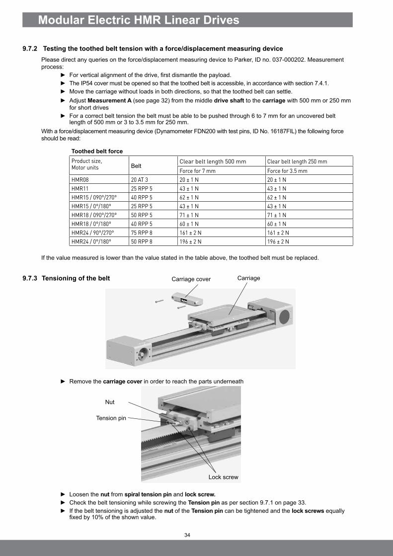
9.7.2 Testing the toothed belt tension with a force/displacement measuring devicePlease direct any queries on the force/displacement measuring device to Parker, ID no. 037-000202. Measurement process:
► For vertical alignment of the drive, first dismantle the payload. ► The IP54 cover must be opened so that the toothed belt is accessible, in accordance with section 7.4.1. ► Move the carriage without loads in both directions, so that the toothed belt can settle. ► Adjust Measurement A (see page 32) from the middle drive shaft to the carriage with 500 mm or 250 mm
for short drives ► For a correct belt tension the belt must be able to be pushed through 6 to 7 mm for an uncovered belt
length of 500 mm or 3 to 3.5 mm for 250 mm.With a force/displacement measuring device (Dynamometer FDN200 with test pins, ID No. 16187FIL) the following force should be read:
Toothed belt forceProduct size, Motor units Belt
Clear belt length 500 mm Clear belt length 250 mmForce for 7 mm Force for 3.5 mm
HMR08 20 AT 3 20 ± 1 N 20 ± 1 NHMR11 25 RPP 5 43 ± 1 N 43 ± 1 NHMR15 / 090°/270° 40 RPP 5 62 ± 1 N 62 ± 1 NHMR15 / 0°/180° 25 RPP 5 43 ± 1 N 43 ± 1 NHMR18 / 090°/270° 50 RPP 5 71 ± 1 N 71 ± 1 NHMR18 / 0°/180° 40 RPP 5 60 ± 1 N 60 ± 1 NHMR24 / 90°/270° 75 RPP 8 161 ± 2 N 161 ± 2 NHMR24 / 0°/180° 50 RPP 8 196 ± 2 N 196 ± 2 N
If the value measured is lower than the value stated in the table above, the toothed belt must be replaced.
9.7.3 Tensioning of the belt
► Remove the carriage cover in order to reach the parts underneath
► Loosen the nut from spiral tension pin and lock screw. ► Check the belt tensioning while screwing the Tension pin as per section 9.7.1 on page 33. ► If the belt tensioning is adjusted the nut of the Tension pin can be tightened and the lock screws equally
fixed by 10% of the shown value.
CarriageCarriage cover
Lock screw
Nut
Tension pin

35
EN
► Loosen the carriage cover in the direction of the end cap drive end side in order to reach the screws underneath.
► Place something such as wood underneath the screw. ► Loosen the screws from the end cap non drive end side and remove the cover.
► Remove the six screws of the nut slot.
ATTENTIONRisk of damage to runner blocks
Tilting will damage the recirculating ball runner block! ► Carefully move carriage onto the guide rails with a parallel movement.
► Carefully move the carriage from the guide, without tilting, and insert the transport safety device such that no balls fall out of the runner block.
9.8 Checking the Cover FunctionWith the IP54 cover, the proper wiper function only occurs when a slight tread can be detected on the Outer band. Scores or streaks of residue indicate defective or dirty wipers around the carriage. Replacement is required.
9.9 Replacing the Carriage
9.9.1 Disassembly of Carriage Ball Screw DriveIf present, the IP54 cover must be removed (refer to section 7.5.1 on page 17).
Nut slot
End cap non drive endCarriage cover
End cap drive end
Carriage
Carriage
Runner block

36
Modular Electric HMR Linear Drives
9.9.2 Installing the carriage ball screw drive
ATTENTIONRisk of damage to runner blocks
Tilting will damage the recirculating ball runner block! ► Carefully move carriage onto the guide rails with a parallel movement.
► Very carefully place the carriage onto the guide rails without tilting. When placing the carriage onto the guide rails, remove the transport safety device.
NOTE ► Adhere to the tightening torques for screws according to section 7.1. on page 12.
► Push the carriage over the nut slot so that the screws can be fitted. Only insert the screws loosely. ► Push the end cap non drive end onto the floating bearing and insert the screws loosely. ► Align the nut slots axially parallel on the inside of the carriage (the stop side). ► Screw the screws in tightly in the nut slot.
► Move the carriage to end cap drive end (the end cap drive end will align itself). ► Align the end cap non drive end horizontally and gradually screw the cover screws down tightly and in
steps.
Nut slot
End cap drive end
Carriage
Carriage
End cap non drive endEnd cap drive end
End cap non drive end
End cap drive end
Screws Nut slot
Cover screws

37
EN
End cap non drive end
► Loosen the screw of the clamping plate and remove it. ► Pull out the belt clamping package. ► Repeat this with the other belt tensioning package. ► This time remove the belt of the belt clamping package.
► Remove cover from the end cap non drive end side. ► Lay out the belt.
► Loosen the screws from end cap non drive end side and remove it.
9.9.3 Disassembly of carriage belt driveIf present, the IP54 cover must be removed as per section 7.5.1 on page 18.The belt tensioning block needs to be removed on both sides. Following the procedure is described for one side.
Carriage cover
► Loosen the carriage cover in order to reach the parts underneath. ► Remove the lock screw. ► Loose the nut of the tension pin a bit and release the pin.
Tension pinNut tension pin
Lock screw
Clamping plateBelt clamping package
Belt
Cover
End cap non drive end

38
Modular Electric HMR Linear Drives
Runner blocks
9.9.4 Installing the carriage belt drive
► Very carefully place the carriage onto the guide rails without tilting. ► When placing the carriage onto the guide rails, remove the transport safety device.
End cap non drive end
NOTE ► Adhere to the tightening torques for screws according to section 7.1 on page 12.
► Place the cover circulation horizontally and in the centre and screw it in tightly. ► Carry back the belt on the upper side of the non drive end pulley. ► Fasten the cover to the end cap non drive end.
Subsequential steps can be done in opposite sequence then disassembly. Finally tension the belt as per section 9.7.2 on page 34.
ATTENTIONRisk of damage to runner blocks!
Tilting will damage the recirculating ball runner block. ► Carefully move carriage onto the guide rails with a parallel movement.
► Carefully move the carriage from the guide, without tilting and insert the transport safety device such that no balls fall out of the runner block.
Carriage

39
EN
9.10 Replacing the Carriage
9.10.1 Disassembly of Carriage Ball Screw Drive
► Loosen the carriage cover and the cover sheet in order to reach the screws underneath. ► Loosen the screws on the nut slot. ► Loosen the screws on the end cap drive end. ► Loosen the screws on the end cap non drive end.
► Pull the cover drive out with the complete drive body.
► Remove the terminal ring for securing the spindle bearing and pull off the cover drive from the spindle bearing.
► Remove the circlip of the floating bearing in the cover circulation and remove the bearing from the cover.
End cap drive end
End cap non drive end
End cap drive end
Nut slot
Carriage coverEnd cap non drive end
Cover sheet
Nut slot
Ball screw drive
Ball screw nut
Spindle bearing
Clamping ring
40
Modular Electric HMR Linear Drives
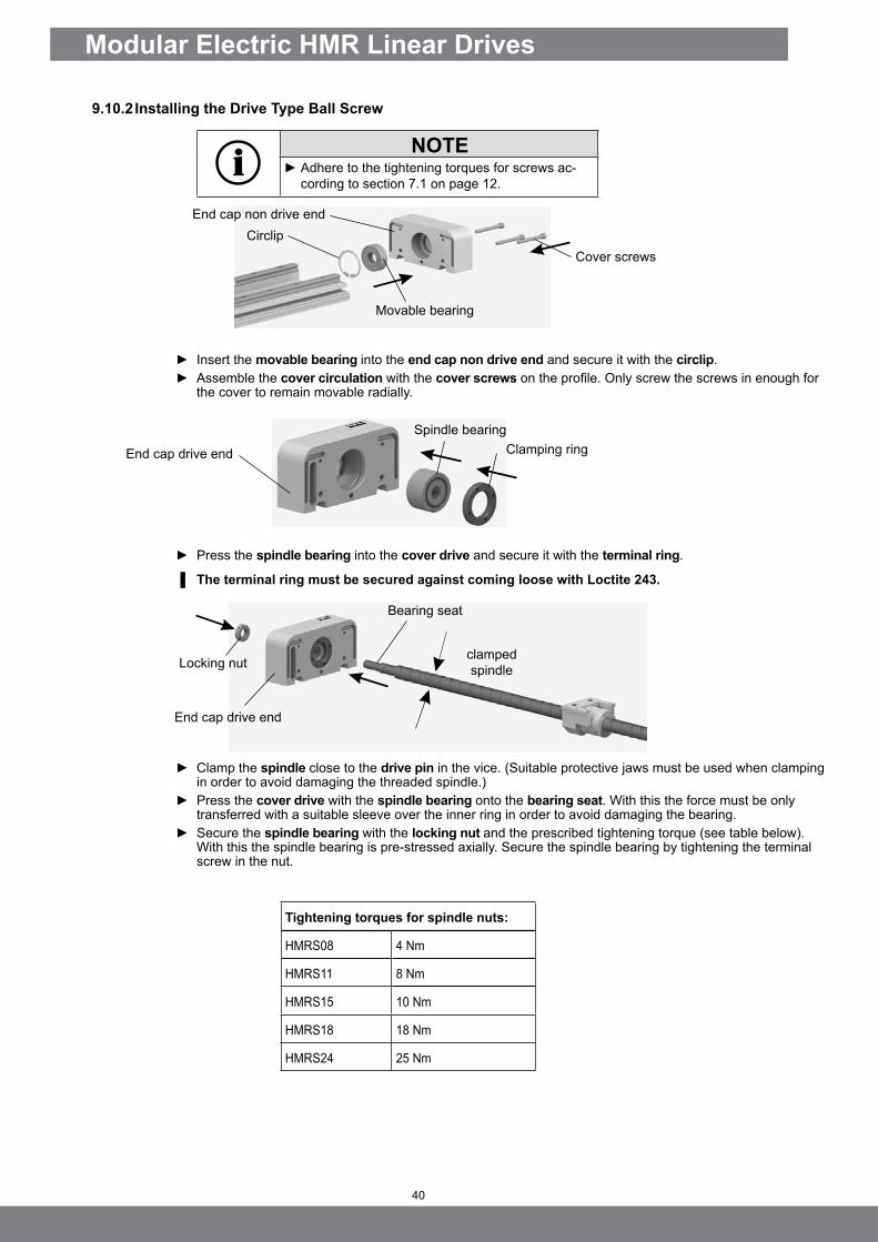
9.10.2 Installing the Drive Type Ball Screw
NOTE ► Adhere to the tightening torques for screws ac-cording to section 7.1 on page 12.
► Insert the movable bearing into the end cap non drive end and secure it with the circlip. ► Assemble the cover circulation with the cover screws on the profile. Only screw the screws in enough for
the cover to remain movable radially.
► Press the spindle bearing into the cover drive and secure it with the terminal ring.
▐ The terminal ring must be secured against coming loose with Loctite 243.
► Clamp the spindle close to the drive pin in the vice. (Suitable protective jaws must be used when clamping in order to avoid damaging the threaded spindle.)
► Press the cover drive with the spindle bearing onto the bearing seat. With this the force must be only transferred with a suitable sleeve over the inner ring in order to avoid damaging the bearing.
► Secure the spindle bearing with the locking nut and the prescribed tightening torque (see table below). With this the spindle bearing is pre-stressed axially. Secure the spindle bearing by tightening the terminal screw in the nut.
End cap drive end
Spindle bearingClamping ring
End cap non drive end
Cover screws
Movable bearing
End cap drive end
Bearing seat
clamped spindleLocking nut
Circlip
Tightening torques for spindle nuts:
HMRS08 4 Nm
HMRS11 8 Nm
HMRS15 10 Nm
HMRS18 18 Nm
HMRS24 25 Nm
41
EN
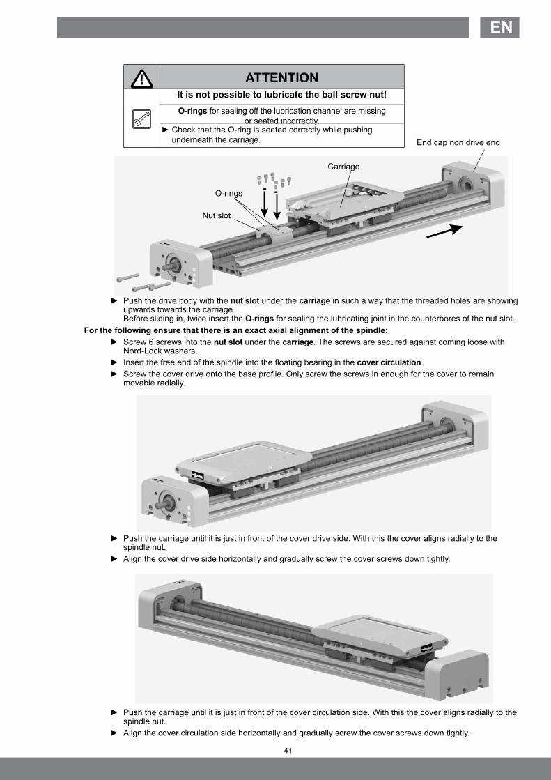
ATTENTIONIt is not possible to lubricate the ball screw nut!O-rings for sealing off the lubrication channel are missing
or seated incorrectly. ► Check that the O-ring is seated correctly while pushing underneath the carriage.
► Push the drive body with the nut slot under the carriage in such a way that the threaded holes are showing upwards towards the carriage. Before sliding in, twice insert the O-rings for sealing the lubricating joint in the counterbores of the nut slot.
For the following ensure that there is an exact axial alignment of the spindle: ► Screw 6 screws into the nut slot under the carriage. The screws are secured against coming loose with
Nord-Lock washers. ► Insert the free end of the spindle into the floating bearing in the cover circulation. ► Screw the cover drive onto the base profile. Only screw the screws in enough for the cover to remain
movable radially.
► Push the carriage until it is just in front of the cover drive side. With this the cover aligns radially to the spindle nut.
► Align the cover drive side horizontally and gradually screw the cover screws down tightly.
► Push the carriage until it is just in front of the cover circulation side. With this the cover aligns radially to the spindle nut.
► Align the cover circulation side horizontally and gradually screw the cover screws down tightly.
Nut slot
Carriage
O-rings
End cap non drive end

42
Modular Electric HMR Linear Drives
9.10.3 Disassembly of Drive Type BeltIf present, the IP54 cover must be removed as per section 7.4.1 on page 18.The belt tensioning block needs to be removed on both sides. Following the procedure is described for one side.
Carriage cover
► Loosen the carriage cover in order to reach the parts underneath.
► Remove the lock screw. ► Loose the nut of the tension pin a bit and release the pin.
► Loosen the screw of the clamping plate and remove it. ► Pull out the belt clamping package.
Tension pinNut tension pin
Lock screw
Belt clamping package
Clamping plate
43
EN
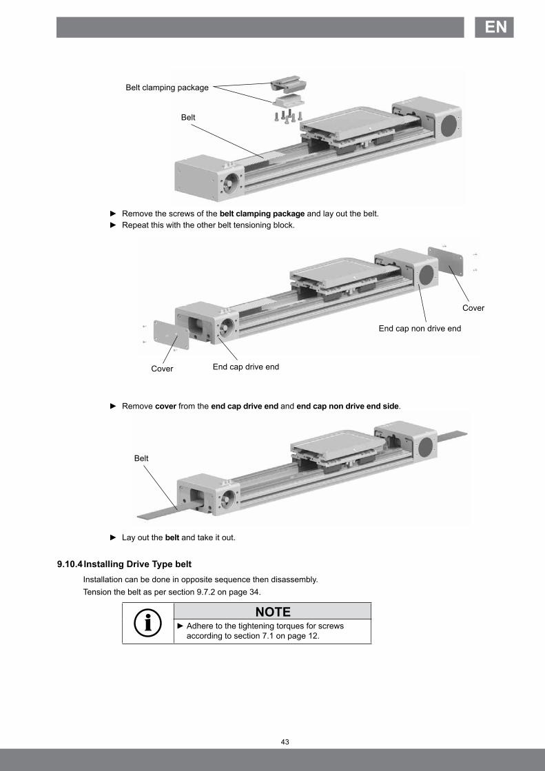
► Remove the screws of the belt clamping package and lay out the belt. ► Repeat this with the other belt tensioning block.
► Remove cover from the end cap drive end and end cap non drive end side.
► Lay out the belt and take it out.
9.10.4 Installing Drive Type beltInstallation can be done in opposite sequence then disassembly. Tension the belt as per section 9.7.2 on page 34.
NOTE ► Adhere to the tightening torques for screws according to section 7.1 on page 12.
Belt
Belt
Belt clamping package
Cover
End cap non drive end
End cap drive endCover

44
Modular Electric HMR Linear Drives
10 Decommissioning
10.1 Disassembly of a Machine or SystemDisassembly and the final shutdown of the HMR must be carried out by trained mechanical or electrical specialists.No stored energy (springs, fluid, pressure).
CAUTIONCrushing hazard due to unexpected movements
This could result in severe injuries or damage to property.
► Bring system to a standstill and secure.
► Pay attention to the weight of any loads being lifted during vertical installation. ► Screws and toothed belts are not self-locking, which means that the Drive Type, carriage and load
could crash down.
10.2 DisposalThe HMR does not contain any hazardous substances that require special attention during disposal. Lubricant residue is possible and should be expected.In addition to the main aluminum component, there are also installed steel parts and plastics such as PU and NBR. Non-ferrous metal is present in small quantities only.Electrical components (if used during operation) such as the motor and electronic switches must be disposed of according to the local regulations in force.

45
EN
11 Retrofit Kits
11.1 IP54 CoverIf the cover is to be completely retrofitted, the product key must be indicated. Example: HMRS15C100-1200-000000000 Example: HMRB15CBD0-1200-000000000To ensure that the cover and the Outer band are delivered in the correct design and length, the following must be made known at the very least:• Drive type (S = ball screw drive / B = belt)• Product size (15 = width 150 mm)• Drive type (C = profile basis with ball screw and IP54 cover)• Carriage version: (0 = standard)• Order Stroke (1200 = 1200 mm) • Homing switch (0 = without)• End switch (0 = without)• Assembly position switch (0 = without End switch)
Order numbers for the IP54 cover
Product size Order number
HMRx08xxx0-xxxx-XXXxxxxxx 56123-XX-0…
HMRx11xxx0-xxxx-XXXxxxxxx 56124-XX-0…
HMRx15xxx0 56100-0…
HMRx18xxx0 56101-0…
HMRx24xxx0 56102-0…
HMRx08xxx1-xxxx-XXXxxxxxx, HMRx08xxx2-xxxx-XXXxxxxxx 56123-XX-1…
HMRx11xxx1-xxxx-XXXxxxxxx, HMRx11xxx2-xxxx-XXXxxxxxx 56124-XX-1…
HMRx15xxx1, HMRx15xxx2 56100-1…
HMRx18xxx1, HMRx18xxx2 56101-1…
HMRx24xxx1, HMRx24xxx2 56102-1…
Lateral wiper
Outer band
Clamping plate outer band
Sealing band
Cover
Inner strip guide
Holder cover
A-band coating

46
Modular Electric HMR Linear Drives
M8 - Connector
11.2 Position Detection internal and externalFor connecting up to a maximum of three magnetic switches, you will require the corresponding number of M8 mount-ed connectors. Use, installation and connection are described in section 7.5 cont. With the external position detection the solenoid switches are fixed in the groove of the cover profile. The IP54 cover is required for this.
Order numbers for parts for internal position detection
Designation Order number
M8 mounted connector 54519FIL
Order numbers for parts for external position detection
T-slot cable holder T-Nut, VP 5St 56350FIL
M8 connector with cable 5 m KL3186
M8 connector with cable 10 m KL3217
M8 connector with cable 15 m KL3216
Position detection extern intern/extern
MagnetschalterM8 connector, snap in FL = open lead
0.3 m 3 m 10 mR2NO-I: Reed, 2-wire, normally open NO, internal P8S-GRSHX P8S-GRFAX P8S-GRFDX
R2NC-I: Reed, 2-wire, normaly closed NC, internal P8S-GESNX P8S-GEFFX P8S-GEFRX
P3NO-I: PNP, 3-wire, normally open NO, internal P8S-GPSHX P8S-GPFAX P8S-GPFDX
P3NC-I: PNP, 3-wire, normaly closed NC, internal P8S-GQSHX P8S-GQFAX P8S-GQFDX
N3NO-I: PNP, 3-wire, normally open NO, internal P8S-GNSHX P8S-GNFAX P8S-GNFDX
N3NC-I: PNP, 3-wire, normaly closed NC, internal P8S-GMSHX P8S-GMFAX P8S-GMFDX
T-slot switch
47
EN
12 Spare Part / Wearing Part Kits
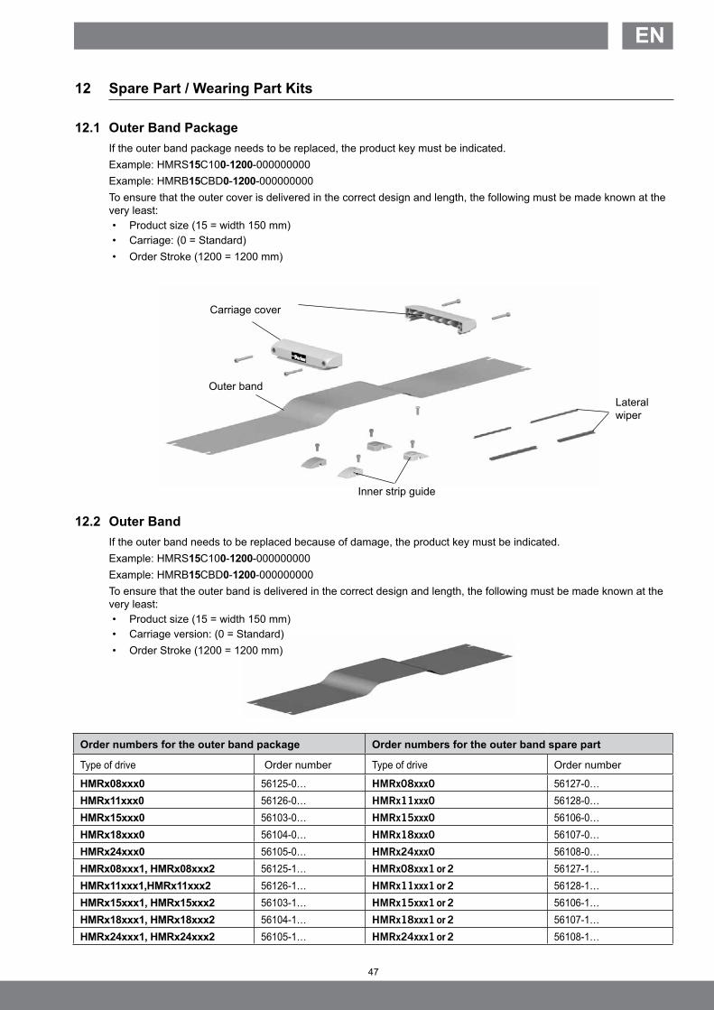
12.1 Outer Band PackageIf the outer band package needs to be replaced, the product key must be indicated. Example: HMRS15C100-1200-000000000 Example: HMRB15CBD0-1200-000000000To ensure that the outer cover is delivered in the correct design and length, the following must be made known at the very least:• Product size (15 = width 150 mm)• Carriage: (0 = Standard)• Order Stroke (1200 = 1200 mm)
12.2 Outer Band If the outer band needs to be replaced because of damage, the product key must be indicated.Example: HMRS15C100-1200-000000000 Example: HMRB15CBD0-1200-000000000To ensure that the outer band is delivered in the correct design and length, the following must be made known at the very least:• Product size (15 = width 150 mm)• Carriage version: (0 = Standard)• Order Stroke (1200 = 1200 mm)
Carriage cover
Lateral wiper
Outer band
Inner strip guide
Order numbers for the outer band package Order numbers for the outer band spare part
Type of drive Order number Type of drive Order number
HMRx08xxx0 56125-0… HMRx08xxx0 56127-0…HMRx11xxx0 56126-0… HMRx11xxx0 56128-0…HMRx15xxx0 56103-0… HMRx15xxx0 56106-0…HMRx18xxx0 56104-0… HMRx18xxx0 56107-0…HMRx24xxx0 56105-0… HMRx24xxx0 56108-0…HMRx08xxx1, HMRx08xxx2 56125-1… HMRx08xxx1 or 2 56127-1…HMRx11xxx1,HMRx11xxx2 56126-1… HMRx11xxx1 or 2 56128-1…HMRx15xxx1, HMRx15xxx2 56103-1… HMRx15xxx1 or 2 56106-1…HMRx18xxx1, HMRx18xxx2 56104-1… HMRx18xxx1 or 2 56107-1…HMRx24xxx1, HMRx24xxx2 56105-1… HMRx24xxx1 or 2 56108-1…

48
Modular Electric HMR Linear Drives
12.3 Drive Type Ball ScrewIf the drive type is to be replaced, the product key must be indicated. Example: HMRS15C100-1200-000000000 To ensure that a suitable drive type can be delivered, the following must be known at the very least: • Product size (15 = width 150 mm)• Spindle version (10 = pitch 10 mm with plain shaft)• Carriage: (0 = Standard)• Order Stroke (1200 = 1200 mm)
Order numbers for the ball screw
Type of drive Comments Order number
HMRS08x05… KGS 12X05-P 56129-…HMRS08x12… KGS 12X12-P 56130-…HMRS11x05… KGS 16X05-P 56131-…HMRS11x16… KGS 16X16-P 56132-…HMRS15x05… KGS 20X05-P 56109-…HMRS15x20… KGS 20X20-P 56110-…HMRS18x10… KGS 25X10-P 56111-…HMRS18x25… KGS 25X25-P 56112-…HMRS24x10… KGS 32X10-P 56113-…HMRS24x32… KGS 32X32-P 56114-…
Nut slot
Spindle bearing Ball screw nut
Ball screw drive Movable bearing

49
EN
12.4 Carriage Belt DriveIf the belt is to be replaced, the product key must be indicated. Example: HMRB15CBD0-1200-000000000To ensure that a suitable belt can be delivered, the following must be known at the very least:• Product size (15 = width 150 mm)• Motor mounting position (BD = 090° front with double plain shaft)• Carriage: (0 = Standard)• Order Stroke (1200 = 1200 mm)
Order numbers belt
Type of drive Comments Order number
HMRB08xxx0…, HMRB08xxx1… Motor mounting 090/270, 000/180, 20AT3 56209-0…
HMRB11xxx0…, HMRB11xxx1… Motor mounting 090/270, 000/180, 25RPP5 56210-0…
HMRB15xBD0…, HMRB15xDD0…, HMRB15xBD1…, HMRB15xDD1…"
Motor mounting 090/270, 40RPP5 56200-0…
HMRB15xAP0…, HMRB15xAD0…, HMRB15xAP1…, HMRB15xAD1…"
Motor mounting 000/180, 25RPP5 56201-0…HMRB15xCP0…, HMRB15xCD0…, HMRB15xCP1…, HMRB15xCD1…"
HMRB18xBD0…, HMRB18xDD0…, HMRB18xBD1…, HMRB18xDD1…"
Motor mounting 090/270, 50RPP5 56202-0…
HMRB18xAP0…, HMRB18xAD0…, HMRB18xAP1…, HMRB18xAD1…"
Motor mounting 000/180, 40RPP5 56203-0…HMRB18xCP0…, HMRB18xCD0…, HMRB18xCP1…, HMRB18xCD1…"
HMRB24xBD0…, HMRB24xDD0…, HMRB24xBD1…, HMRB24xDD1…"
Motor mounting 090/270, 75RPP8 56204-0…
HMRB24xAP0…, HMRB24xAD0…, HMRB24xAP1…, HMRB24xAD1…"
Motor mounting 000/180, 50RPP8 56205-0…HMRB24xCP0…, HMRB24xCD0…, HMRB24xCP1…, HMRB24xCD1…"
Order numbers belt BI-PART
HMRB08xAP2…, HMRB08xAD2…Motor mounting 000/180, 20AT3 56209-2…
HMRB08xCP2…, HMRB08xCD2…
HMRB11xAP2…, HMRB11xAD2…Motor mounting 000/180, 25RPP5 56210-2…
HMRB11xCP2…, HMRB11xCD2…
HMRB15xAP2…, HMRB15xAD2…Motor mounting 000/180, 25RPP5 56201-2…
HMRB15xCP2…, HMRB15xCD2…
HMRB18xAP2…, HMRB18xAD2…Motor mounting 000/180, 40RPP5 56203-2…
HMRB18xCP2…, HMRB18xCD2…
HMRB24xAP2…, HMRB24xAD2…Motor mounting 000/180, 50RPP8 56205-2…
HMRB24xCP2…, HMRB24xCD2…

50
Modular Electric HMR Linear Drives
12.5 Carriage Ball Screw DriveIf a carriage ball screw drive is to be replaced, the product key must be indicated. Example: HMRS15C100-1200-000000000To ensure that a suitable carriage can be delivered, the following must be known at the very least: • Drive type S = Ball screw drive• Product size (15 = width 150 mm)• Carriage: (0 = Standard)• Order Stroke (1200 = 1200 mm)
Order Numbers Carriage Ball Screw Drive
Type of drive Comments Order number
HMRS08xxx0… Standard 56133FIL
HMRS11xxx0… Standard 56134FIL
HMRS15xxx0… Standard 56115FIL
HMRS18xxx0… Standard 56116FIL
HMRS24xxx0… Standard 56117FIL
HMRS08xxx1… Tandem 56211FIL
HMRS11xxx1… Tandem 56212FIL
HMRS15xxx1… Tandem 56206FIL
HMRS18xxx1… Tandem 56207FIL
HMRS24xxx1… Tandem 56208FIL
For version carriage tandem: 1x carriage Standard and 1x carriage Tandem necessary.
Magnetic package Runner block

51
EN
12.6 Carriage Belt DriveIf the carriage belt is to be replaced, the product key must be indicated. Example: HMRB15CBD0-1200-000000000To ensure that a suitable carriage can be delivered, the following must be known at the very least:• Drive type B = Belt• Product size (15 = width 150 mm)• Motor mounting position (BD = 090° front with double plain shaft)• Carriage: (0 = Standard)• Order Stroke (1200 = 1200 mm)
Order numbers carriage belt drive
Type of drive Comments Order number
HMRB08xxx0…, HMRB08xxx1…, HMRB08xxx2… Standard/Tandem/Bipart 56211FIL
HMRB11xxx0…, HMRB11xxx1…, HMRB11xxx2… Standard/Tandem/Bipart 56212FIL
HMRB15xxx0…, HMRB15xxx1…, HMRB15xxx2… Standard/Tandem/Bipart 56206FIL
HMRB18xxx0…, HMRB18xxx1…, HMRB18xxx2… Standard/Tandem/Bipart 56207FIL
HMRB24xxx0…, HMRB24xxx1…, HMRB24xxx2… Standard/Tandem/Bipart 56208FIL
For version tandem/Bipart: 2x carriage Standard necessary.
Runner block
Magnetic package
Carriage

52
Modular Electric HMR Linear Drives
Drive shaft
Non drive end shaft
Double plain shaft “D”
Plain shaft “P”
Order numbers drive shaft belt driveType of drive Comments Order numberHMRB08xBD…, HMRB08xDD… Motor mounting 090/270, double plain shaft 56213FIL
HMRB08xAP…, HMRB08xCP… Motor mounting 000/180, plain shaft 56214FIL
HMRB08xAD…, HMRB08xCD… Motor mounting 000/180, double plain shaft 56213FIL
HMRB08xAP…, HMRB08xCP…, HMRB08xAD…, HMRB08xCD… Motor mounting 000/180, non drive end shaft 56215FIL
HMRB11xBD…, HMRB11xDD… Motor mounting 090/270, double plain shaft 56216FIL
HMRB11xAP…, HMRB11xCP… Motor mounting 000/180, plain shaft 56217FIL
HMRB11xAD…, HMRB11xCD… Motor mounting 000/180, double plain shaft 56216FIL
HMRB11xAP…, HMRB11xCP…, HMRB11xAD…, HMRB11xCD… Motor mounting 000/180, non drive end shaft 56218FIL
HMRB15xBD…, HMRB15xDD… Motor mounting 090/270, double plain shaft 56150FIL
HMRB15xAP…, HMRB15xCP… Motor mounting 000/180, plain shaft 56151FIL
HMRB15xAD…, HMRB15xCD… Motor mounting 000/180, double plain shaft 56152FIL
HMRB15xAP…, HMRB15xCP…, HMRB15xAD…, HMRB15xCD… Motor mounting 000/180, non drive end shaft 56153FIL
HMRB18xBD…, HMRB18xDD… Motor mounting 090/270, double plain shaft 56154FIL
HMRB18xAP…, HMRB18xCP… Motor mounting 000/180, plain shaft 56155FIL
HMRB18xAD…, HMRB18xCD… Motor mounting 000/180, double plain shaft 56156FIL
HMRB18xAP…, HMRB18xCP…, HMRB18xAD…, HMRB18xCD… Motor mounting 000/180, non drive end shaft 56157FIL
HMRB24xBD…, HMRB24xDD… Motor mounting 090/270, double plain shaft 56158FIL
HMRB24xAP…, HMRB24xCP… Motor mounting 000/180, plain shaft 56159FIL
HMRB24xAD…, HMRB24xCD… Motor mounting 000/180, double plain shaft 56160FIL
HMRB24xAP…, HMRB24xCP…, HMRB24xAD…, HMRB24xCD… Motor mounting 000/180, non drive end shaft 56161FIL
Bearing
Clamping ring
12.7 Drive Shafts BeltIf one of the drive shafts have to be replaced, the product key must be indicated. Example: HMRB15CBD0-1200-000000000 To ensure that a suitable drive shaft can be delivered, the following must be known at the very least:• Drive type B = Belt• Product size (15 = width 150 mm)• Motor mounting position (BD = 090° front with double plain shaft) .

53
EN
12.8 Belt Tensioning BlockIf the tensioning block is to be replaced, the product key must be indicated. Example: HMRB15CBD0-1200-000000000 To ensure that a suitable tension block can be delivered, the following must be known at the very least:• Drive type B = Belt• Product size (15 = width 150 mm)• Motor mounting position (BD = 090° front double plain shaft)• Carriage: (0 = Standard)
Order number tension block Belt Drive
Type of drive Comments Order number
HMRB08xBD…, HMRB08xDD… Motor mounting 090/270, Standard 56219FILHMRB08xAP…, HMRB08xCP…, HMRB08xAD…, HMRB08xCD… Motor mounting 000/180, Standard/Bipart 56220FILHMRB11xBD…, HMRB11xDD… Motor mounting 090/270, Standard 56221FILHMRB11xAP…, HMRB11xCP…, HMRB11xAD…, HMRB11xCD… Motor mounting 000/180, Standard/Bipart 56222FILHMRB15xBD…, HMRB15xDD… Motor mounting 090/270, Standard 56162FILHMRB15xAP…, HMRB15xCP…, HMRB15xAD…, HMRB15xCD… Motor mounting 000/180, Standard/Bipart 56163FILHMRB18xBD…, HMRB18xDD… Motor mounting 090/270, Standard 56164FILHMRB18xAP…, HMRB18xCP…, HMRB18xAD…, HMRB18xCD… Motor mounting 000/180, Standard/Bipart 56165FILHMRB24xBD…, HMRB24xDD… Motor mounting 090/270, Standard 56166FILHMRB24xAP…, HMRB24xCP…, HMRB24xAD…, HMRB24xCD… Motor mounting 000/180, Standard/Bipart 56167FIL
Clamping plate
Tighten plate
Toothed belt lock
Tension pin Pusher

54
Modular Electric HMR Linear Drives
12.9 Impact protection If the impact protection is to be replaced, the product key must be indicated. Example: HMRS15C100-1200-000000000 Example: HMRB15CBD0-1200-000000000 To ensure that a suitable impact protection can be delivered, the following must be known at the very least:• Product size (15 = width 150mm) • Carriage: (0 = Standard)
Order number for impact protection
Type of drive Order number
HMRx08 56135FIL
HMRx11 56118FIL
HMRx15 56118FIL
HMRx18 56119FIL
HMRx24 56119FIL
Distance
Shock absorber

55
EN
13 Declaration of Incorporation

© 2014 Parker Hannifin Corporation. All rights reserved. P-A7P021GB 02/2014