Embed Size (px)
Citation preview
Thorsten Reuther + Hardy Hofmann
Hofmann CERAMIC GmbH
Metal - Filtration
Re - Imagined

a) Sieving effect
b) Filtercake
c) Deep bed filtration
Fig.1 Mechanisms of cermamic filters

3 step filtration

Figure 2a : Slag layer – foam ceramic filter.

Figure 2b : Slag layer – extruded filter.

Diagram 1 : Relation filtersurface / filtration effect
Filtration effect
Filter surface

50%-ige- Reduzierung des
Filtrationseffektes??
Bild 2 Dickenreduzierung bei Schaumkeramikfilter Reduction of thickness (foam filter)

Fig. 3a : “Blocked Filter”. View from below.

Figure 3b : “Blocked Filter”. Side view.

Figure 4 : Open areas of a pressed and extruded filter.

Filter type DimensionCell- /
holesizeOpen Area
% of
open
Area
Cellfilter, 50csi100 x
75mm
2,95 x
2,95mm5056mm² 67%
Round hole filter100 x
75mmØ 2,17mm 3142mm² 42%
Cellfilter, 50csi100 x
100mm
2,95 x
2,95mm6752mm² 67%
Round hole filter100 x
100mmØ 2,81mm 4165mm² 42%
Comparison of the geometries of extruded filters (cellfilters)
and pressed round hole filters
Table 1

Filter type DimensionCell- /
holesizeOpen Area
% of
open
Area
Cellfilter, 50csi100 x
75mm
2,95 x
2,95mm5056mm² 67%
Round hole filter100 x
75mmØ 3,30mm 3650mm² 49%
Cellfilter, 50csi100 x
100mm
2,95 x
2,95mm6752mm² 67%
Round hole filter100 x
100mmØ 3,50mm 5164mm² 52%
Comparison of the geometries of extruded filters (cellfilters)
with the new designed pressed round hole filters
Table 2

Figure 5 : Strainer core Ø 230x30mm.
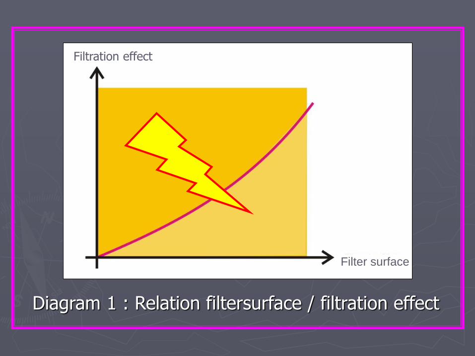
Diagram 1 : Relation filtersurface / filtration effect
Filtration effect
Filter surface

Figure 6 : Flow in front and after a filter.

Figure 7 : Scheme of the function of a strainer core.

Inclusions
Tailback
Figure 8 : Flow in front and after a filter.

Figure 9: Flow simulation with water.

Figure 10: Inclusions in front of the filters.

Figure 11 :“ Clean” filterstructure.

Figure 12 : Impurities in front of a pressed round hole filter.
Pressed filter
Impurities
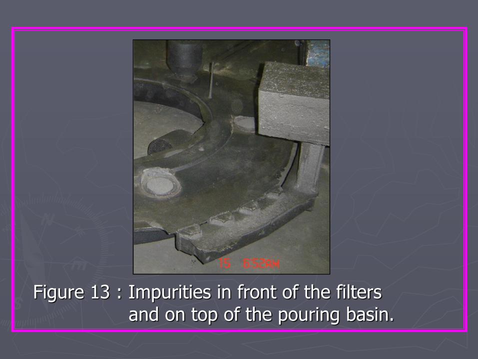
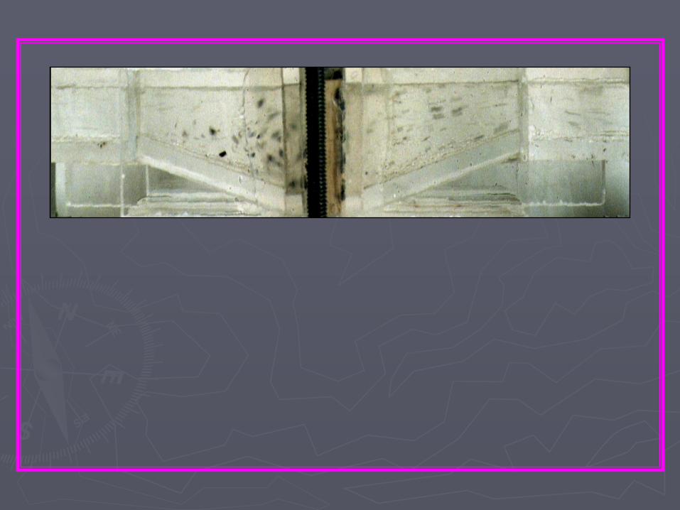
Figure 13 : Impurities in front of the filters and on top of the pouring basin.

Figure 14 : Impurities in front of filters.
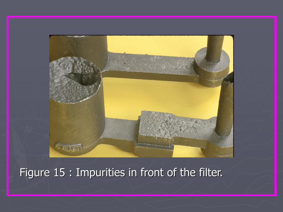
Figure 15 : Impurities in front of the filter.

Diagram 2 : Ratio of volumetric flow and flow resistance to the filtering capacity.
Volumetric flow
Flow resistance
Filtration effect /
Efficiency
2
1
Optimal
area

For additional information, please contact:
Hardy Hofmann
Mühlweg 14, 35767 Breitscheid, Gemany
+49 (0) 2777/9145-0
+49 (0) 2777/9145-55
www.hofmann-ceramic.de

“Glück auf”
Thank you for
your attention!