Embed Size (px)
Citation preview
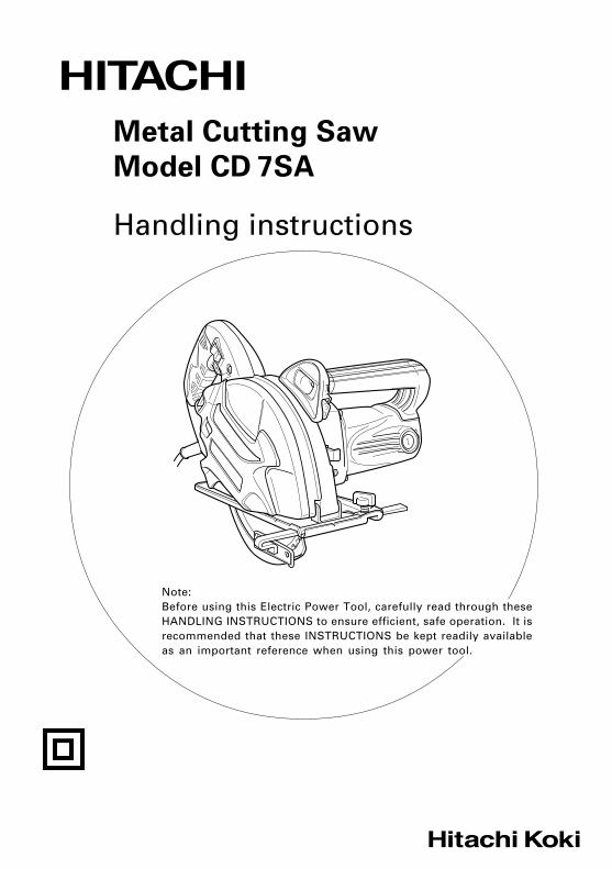
Metal Cutting Saw
Model CD 7SA
Handling instructions
Note:Before using this Electric Power Tool, carefully read through theseHANDLING INSTRUCTIONS to ensure efficient, safe operation. It isrecommended that these INSTRUCTIONS be kept readily availableas an important reference when using this power tool.
001Cover_CD7SA_Eng 5/15/09, 15:091
2
GENERAL SAFETY RULES
WARNING!Read all instructionsFailure to follow all instructions listed below may result inelectric shock, fire and/or serious injury.The term “power tool” in all of the warnings listed belowrefers to your mains operated (corded) power tool or batteryoperated (cordless) power tool.
SAVE THESE INSTRUCTIONS1) Work area
a) Keep work area clean and well lit.Cluttered and dark areas invite accidents.
b) Do not operate power tools in explosiveatmospheres, such as in the presence of flammableliquids, gases or dust.Power tools create sparks which may ignite thedust of fumes.
c) Keep children and bystanders away while operatinga power tool.Distractions can cause you to lose control.
2) Electrical safetya) Power tool plugs must match the outlet.
Never modify the plug in any way.Do not use any adapter plugs with earthed(grounded) power tools.Unmodified plugs and matching outlets will reducerisk of electric shock.
b) Avoid body contact with earthed or groundedsurfaces such as pipes, radiators, ranges andrefrigerators.There is an increased risk of electric shock if yourbody is earthed or grounded.
c) Do not expose power tools to rain or wetconditions.Water entering a power tool will increase the riskof electric shock.
d) Do not abuse the cord. Never use the cord forcarrying, pulling or unplugging the power tool.Keep cord away from heat, oil, sharp edges ormoving parts.Damaged or entangled cords increase the risk ofelectric shock.
e) When operating a power tool outdoors, use anextension cord suitable for outdoor use.Use of a cord suitable for outdoor use reducesthe risk of electric shock.
f) Recommendation for the use of residual currentdevice with a rated residual current of 30mAor less.
3) Personal safetya) Stay alert, watch what you are doing and use
common sense when operating a power tool.Do not use a power tool while you are tired orunder the influence of drugs, alcohol or medication.A moment of inattention while operating powertools may result in serious personal injury.
b) Use safety equipment. Always wear eye protection.Safety equipment such as dust mask, non-skidsafety shoes, hard hat, or hearing protection usedfor appropriate conditions will reduce personalinjuries.
c) Avoid accidental starting. Ensure the switch is inthe off position before plugging in.Carrying power tools with your finger on theswitch or plugging in power tools that have theswitch on invites accidents.
d) Remove any adjusting key or wrench beforeturning the power tool on.A wrench or a key left attached to a rotating partof the power tool may result in personal injury.
e) Do not overreach. Keep proper footing and balanceat all times.This enables better control of the power tool inunexpected situations.
f) Dress properly. Do not wear loose clothing orjewellery. Keep your hair, clothing and glovesaway from moving parts.Loose clothes, jewellery or long hair can be caughtin moving parts.
g) If devices are provided for the connection of dustextraction and collection facilities, ensure theseare connected and properly used.Use of these devices can reduce dust related hazards.
4) Power tool use and carea) Do not force the power tool. Use the correct
power tool for your application.The correct power tool will do the job better andsafer at the rate for which it was designed.
b) Do not use the power tool if the switch does notturn it on and off.Any power tool that cannot be controlled with theswitch is dangerous and must be repaired.
c) Disconnect the plug from the power source beforemaking any adjustments, changing accessories, orstoring power tools.Such preventive safety measures reduce the riskof starting the power tool accidentally.
d) Store idle power tools out of the reach of childrenand do not allow persons unfamiliar with thepower tool or these instructions to operate thepower tool.Power tools are dangerous in the hands ofuntrained users.
e) Maintain power tools. Check for misalignment orbinding of moving parts, breakage of parts andany other condition that may affect the powertools’ operation.If damaged, have the power tool repaired beforeuse.Many accidents are caused by poorly maintainedpower tools.
f) Keep cutting tools sharp and clean.Properly maintained cutting tools with sharp cuttingedges are less likely to bind and are easier tocontrol.
g) Use the power tool, accessories and tool bits etc.,in accordance with these instructions and in themanner intended for the particular type of powertool, taking into account the working conditionsand the work to be performed.Use of the power tool for operations different fromintended could result in a hazardous situation.
5) Servicea) Have your power tool serviced by a qualified repair
person using only identical replacement parts.This will ensure that the safety of the power toolis maintained.
01Eng_CD7SA_Eng 5/15/09, 15:202
3
PRECAUTIONKeep children and infirm persons away.When not in use, tools should be stored out of reach ofchildren and infirm persons.
SAFETY INSTRUCTIONS FOR ALL SAWS
DANGER!a) Keep hands away from cutting area and the blade.
Keep your second hand on auxiliary handle, or motorhousing.If both hands are holding the saw, they cannot becut by the blade.
b) Do not reach underneath the workpiece.The guard cannot protect you from the blade belowthe workpiece.
c) Adjust the cutting depth to the thickness of theworkpiece.Less than a full tooth of the blade teeth should bevisible below the workpiece.
d) Never hold piece being cut in your hands or acrossyour leg. Secure the workpiece to a stable platform.It is important to support the work properly tominimize body exposure, blade binding, or loss ofcontrol.
e) Hold power tool by insulated gripping surfaces whenperforming an operation where the cutting tool maycontact hidden wiring or its own cord.Contact with a “live” wire will also make exposedmetal parts of the power tool “live” and shock theoperator.
f) When ripping always use a rip fence or straight edgeguide.This improves the accuracy of cut and reduces thechance of blade binding.
g) Always use blades with correct size and shape(diamond versus round) of arbour holes.Blades that do not match the mounting hardwareof the saw will run eccentrically, causing loss ofcontrol.
h) Never use damaged or incorrect blade washers orbolt.The blade washers and bolt were specially designedfor your saw, for optimum performance and safetyof operation.
� Never use any abrasive wheelsBurst of abrasive wheel cause serious injury ofoperator or persons around the working area.
FURTHER SAFETY INSTRUCTIONS FOR ALLSAWS
Causes and operator prevention of kickback:
– kickback is a sudden reaction to a pinched, boundor misaligned saw blade, causing an uncontrolledsaw to lift up and out of the workpiece toward theoperator;
– when the blade is pinched or bound tightly by thekerf closing down, the blade stalls and the motorreaction drives the unit rapidly back toward theoperator;
– if the blade becomes twisted or misaligned in thecut, the teeth at the back edge of the blade candig into the top surface of the wood causing theblade to climb out of the kerf and jump back towardthe operator.
Kickback is the result of saw misuse and/or incorrectoperating procedures or conditions and can be avoidedby taking proper precautions as given below.
a) Maintain a firm grip with both hands on the saw andposition your arms to resist kickback forces.Position your body either side of the blade, but notin line with the blade.Kickback could cause the saw to jump backwards,but kickback forces can be controlled by the operator,if proper precautions are taken.
b) When blade is binding, or when interrupting a cutfor any reason, release the trigger and hold the sawmotionless in the material until the blade comes to acomplete stop.Never attempt to remove the saw from the work orpull the saw backward while the blade is in motionor kickback may occur.Investigate and take corrective actions to eliminatethe cause of blade binding.
c) When restarting a saw in the workpiece, centre thesaw blade in the kerf and check that saw teeth arenot engaged into the material.If saw blade is binding, it may walk up or kickbackfrom the workpiece as the saw is restarted.
d) Support large panels to minimize the risk of bladepinching and kickback.Large panels tend to sag under their own weight.Supports must be placed under the panel on bothsides, near the line of cut and near the edge of thepanel.
e) Do not use dull or damaged blades.Unsharpened or improperly set blades producenarrow kerf causing excessive friction, blade bindingand kickback.
f) Blade depth and bevel adjusting locking levers mustbe tight and secure before making cut.If blade adjustment shifts while cutting, it maycause binding and kickback.
g) Use extra caution when making a “plunge cut” intoexisting walls or other blind areas.The protruding blade may cut objects that can causekickback.
SAFETY INSTRUCTIONS FOR SAWS WITHINNER PENDULUM GUARD
a) Check lower guard for proper closing before each use.Do not operate the saw if lower guard does not movefreely and close instantly. Never clamp or tie the lowerguard into the open position.If saw is accidentally dropped, lower guard may bebent.Raise the lower guard with the retracting handleand make sure it moves freely and does not touchthe blade or any other part, in all angles and depthof cut. Model CD7SA is not provided with a retractinghandle. Unplug the saw and use the lower guardto determine if it moves frealy.
b) Check the operation of the lower guard spring. If theguard and the spring are not operating properly, theymust be serviced before use.Lower guard may operate sluggishly due to damagedparts, gummy deposits, or build-up of debris.
c) Lower guard should be retracted manually only forspecial cuts such as “plunge cuts” and “compoundcuts”. Raise lower guard by retracting handle and assoon as blade enters the material, the lower guardmust be released.
01Eng_CD7SA_Eng 5/15/09, 15:203
4
Voltage (by areas)* (110 V, 220 V, 230 V, 240 V)
Power Input* 1140 W
No-Load Speed 3700 min–1
Max. cutting depth 63 mm
Saw blade 185 mm (external dia.) × 2.0 mm (thickness) × 20 mm (hole dia.)
Weight (without cord and saw blade) 4.0 kg
* Be sure to check the nameplate on product as it is subject to change by areas.
SPECIFICATIONS
For all other sawing, the lower guard should operateautomatically. Model CD7SA is not designed orintended to perform "plunge cuts" and "compoundcuts".
d) Always observe that the lower guard is covering theblade before placing saw down on bench or floor.An unprotected, coasting blade will cause the saw towalk backwards, cutting whatever is in its path.Be aware of the time it takes for the blade to stopafter switch is released.
PRECAUTIONS ON USING METAL CUTTING SAW
1. Do not use saw blades which are deformed orcracked.
2. Do not use saw blades made of high speed steel. 3. Do not use saw blades which do not comply with
the characteristics specified in these instructions. 4. Do not stop the saw blades by lateral pressure
on the disc. 5. Always keep the saw blades sharp. 6. Ensure that the lower guard moves smoothly and
freely. 7. Never use the metal cutting saw with its lower
guard fixed in the open position.
8. Ensure that the retraction mechanism of the guardsystem operates correctly.
9. Never operate the metal cutting saw with the sawblade turned upward or to the side.
10. Ensure that the material is free of foreign matterssuch as nails.
11. For model CD7SA, the saw blades range shouldbe from 180 mm to 185 mm.
12. For model CD7SA, be careful of brake kickback.Model CD7SA features an electric brake thatfunctions when the switch is released. As thereis some kickback when the brake functions, besure to hold the main body securely.
13. Sparks can sometimes appear caused by brakingoperation when the switch is turned off sincemodel CD7SA employs electric brakes. Beinformed, however, that this phenomenon is nota machine trouble.
14. For model CD7SA, when the brake becomesineffective, replace the carbon brushes with newones.
15. Disconnect the plug from the receptacle beforecarrying out any adjustment, servicing ormaintenance.
STANDARD ACCESSORIES
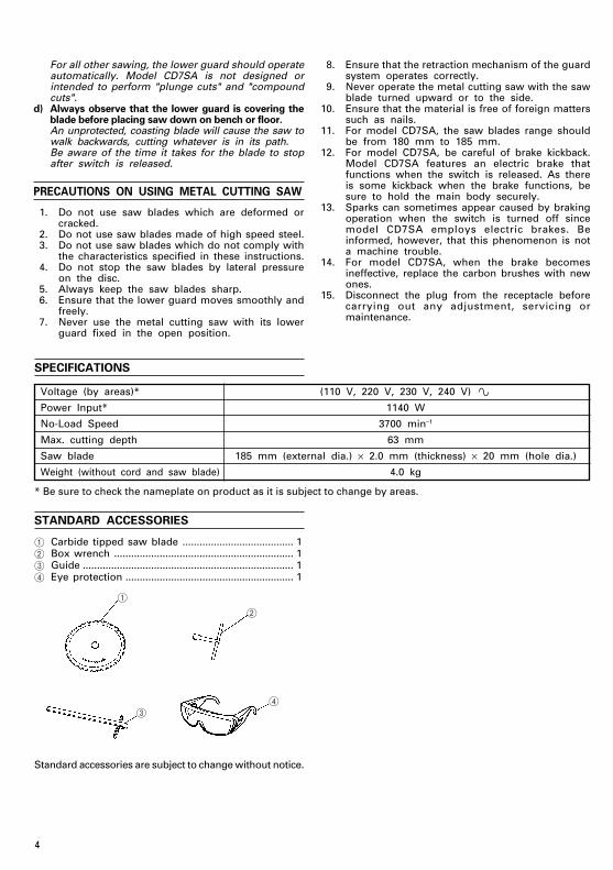
1 Carbide tipped saw blade ....................................... 12 Box wrench ............................................................... 13 Guide .......................................................................... 14 Eye protection ........................................................... 1
4
1
2
3
Standard accessories are subject to change without notice.
01Eng_CD7SA_Eng 5/15/09, 15:204
5
OPTIONAL ACCESSORIES (sold separately)
Carbide tipped saw blade
BladeOuter Hole Tip Thickness of Number
diameter diameter width saw blade of teeth
For cutting soft steel materials180 mm 20 mm 1.8 mm 1.5 mm 34 teeth
185 mm 20 mm 2.0 mm 1.6 mm 38 teeth
For cutting soft steel materials185 mm 20 mm 2.0 mm 1.6 mm 38 teeth
(Low noise type)
For cutting thin,soft steel materials
185 mm 20 mm 2.0 mm 1.6 mm 48 teethFor cutting thin, soft steelmaterials (Low noise type)
For cutting aluminium sash185 mm 20 mm 2.0 mm 1.4 mm 60 teethmaterials
For cutting stainless steelmaterials
180 mm 20 mm 1.8 mm 1.4 mm 56 teeth
Optional accessories are subject to change without notice.
APPLICATION
BladesSoft steel use blade
Tipped saw blades:For cutting soft steelmaterialsFor cutting soft steelmaterials (Low noise type)Tipped saw blades:For cutting thin, soft steelmaterialsFor cutting thin, soft steelmaterials (Low noise type)Tipped saw blades:Aluminum sash materialcutting useTipped saw blades:Stainless steel materialcutting use
Uses� For cutting various types
of soft steel materialssuch as flat steel strips,pipe, steel channels (“C”channels, “L” angles,etc.).
∗ Caution: Cannot be usedfor cutting temperedsteel materials.
� For cutting aluminumsash materials only.
� For cutting stainlesssteel materials such asflat steel sheets, roundpipes, etc.
Sta
nd
ard
acce
sso
ries
Op
tio
nal
acc
esso
ries
power switch is in the ON position, the power toolwill start operating immediately, which could causea serious accident.
4. Extension cordWhen the work area is removed from the powersource, use an extension cord of sufficient thicknessand rated capacity. The extension cord should bekept as short as practicable.
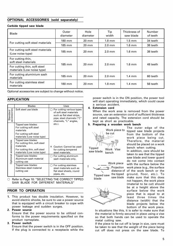
5. Preparing a wooden work benchThe outer edge of thetipped saw blade projectsfrom the bottom of thework piece being cut.Therefore, the materialshould be placed on a workbench when cutting.In addition, care should betaken to see that the tippedsaw blade and lower guarddo not come into contactwith the surface below thework piece (e.g., the surfaceof the work bench or theground, floor, etc.). Tomake sure that this doesnot happen, the work piece(material to be cut) shouldbe at a height above thesurface below the workpiece that is equal to atleast three times thedistance (width) that theblade projects below thebottom of the work piece.
In situations like this, it is safer to make sure thatthe material is firmly secured in place using a viseso that both hands can be used to operate themetal cutting saw.If the piece to be cut off is large in size, care mustbe taken to see that the weight of the piece beingcut off does not press on the saw blade. To
� Refer to Page 10: “SELECTING THE CORRECT TIPPEDSAW BLADE FOR DIFFERENT MATERIALS”
PRIOR TO OPERATION
1. This product has double insulation. However, toavoid electric shocks, be sure to use a power sourcethat is equipped with a circuit breaker to cope withpower leakage and sudden surges.
2. Power sourceEnsure that the power source to be utilized con-forms to the power requirements specified on theproduct nameplate.
3. Power switchEnsure that the power switch is in the OFF position.If the plug is connected to a receptacle while the
Work piece
Work piece tobe cut
ViseWorkbench
Tippedsaw blade
Projectiondistance ofthe tippedsaw blade
Tipped sawblade
01Eng_CD7SA_Eng 5/15/09, 15:205
6
prevent the saw blade from being caught betweenthe two pieces, the piece being cut off should besupported using a stable bench or braced in placeusing wooden supports.If separate wooden supports are to be used tosupport the piece being cut off, when cutting ata work bench, they should be positioned on a flatsurface and fixed in place. It is dangerous to allowthe work bench to wobble or shift position whilecutting materials with the metal cutting saw.
6. Checking to see that the tipped saw blade isattached firmly in positionAlways check to see that the tipped saw bladeis attached firmly in position. For details, see Page11: “ATTACHING AND REMOVING BLADES”.
7. Check the lever to see that is properly tightened.Insufficient tightening of the cutting adjustmentlever may cause personal injury.Be sure to check that it is firmly tightened.
8. Check to see whether the lower guard moves.CAUTION
Do not fasten the lower guard permanentlyin one position. Make sure that it can movesmoothly. Leaving the tipped saw bladeexposed can result in accidents.
The lower guard is used to prevent the body ofthe user from coming into contact with tipped sawblade. Be sure that the lower guard can be movedinto place and is covering the blade. If for anyreason, the lower guard will not move into positionto cover the blade, discontinue the use of themetal cutting saw. Please contact an AuthorizedHitachi Service Center for repair.
9. Making adjustments before using the metal cuttingsaw
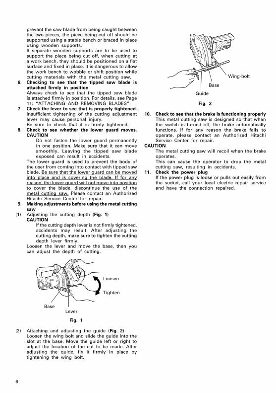
(1) Adjusting the cutting depth (Fig. 1)CAUTION
If the cutting depth lever is not firmly tightened,accidents may result. After adjusting thecutting depth, make sure to tighten the cuttingdepth lever firmly.
Loosen the lever and move the base, then youcan adjust the depth of cutting.
Fig. 1
(2) Attaching and adjusting the guide (Fig. 2)Loosen the wing bolt and slide the guide into theslot at the base. Move the guide left or right toadjust the location of the cut to be made. Afteradjusting the quide, fix it firmly in place bytightening the wing bolt.
BaseLever
Tighten
Loosen
Fig. 2
10. Check to see that the brake is functioning properlyThis metal cutting saw is designed so that whenthe switch is turned off, the brake automaticallyfunctions. If for any reason the brake fails tooperate, please contact an Authorized HitachiService Center for repair.
CAUTIONThe metal cutting saw will recoil when the brakeoperates.This can cause the operator to drop the metalcutting saw, resulting in accidents.
11. Check the power plugIf the power plug is loose or pulls out easily fromthe socket, call your local electric repair serviceand have the connection repaired.
Base
Guide
Wing-bolt
01Eng_CD7SA_Eng 5/15/09, 15:206
7
Steel base supportforms
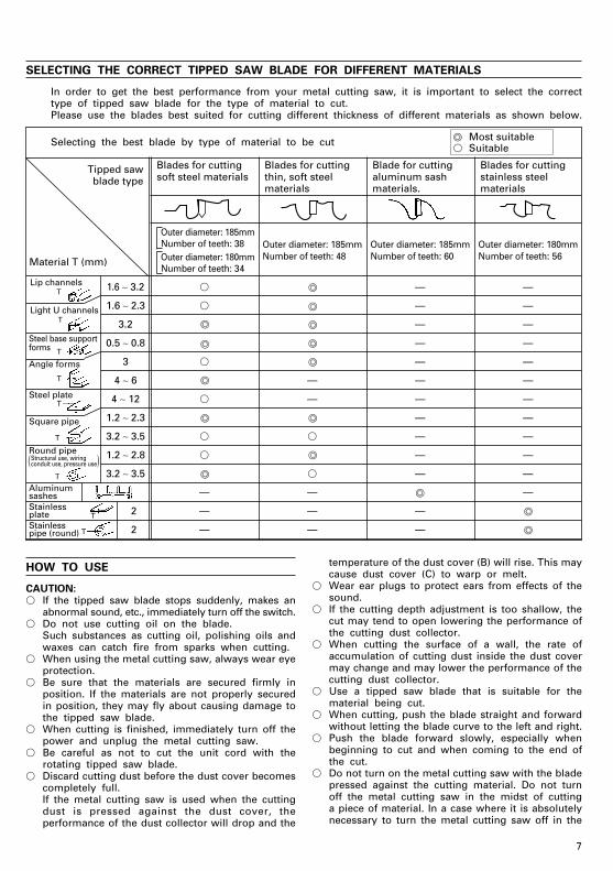
Most suitable� Suitable
Blades for cuttingsoft steel materials
Blades for cuttingthin, soft steelmaterials
Blade for cuttingaluminum sashmaterials.
Tipped sawblade type
Blades for cuttingstainless steelmaterials
Outer diameter: 185mmNumber of teeth: 38 Outer diameter: 185mm Outer diameter: 185mm Outer diameter: 180mmOuter diameter: 180mm Number of teeth: 48 Number of teeth: 60 Number of teeth: 56Number of teeth: 34
Selecting the best blade by type of material to be cut
Material T (mm)
( )
Lip channels
Light U channels
T
T
T
T
TSteel plate
T
Square pipe
T
T
T
Round pipeStructural use, wiringconduit use, pressure use
Angle forms
Stainlessplate
Aluminumsashes
Stainlesspipe (round)
SELECTING THE CORRECT TIPPED SAW BLADE FOR DIFFERENT MATERIALS
In order to get the best performance from your metal cutting saw, it is important to select the correcttype of tipped saw blade for the type of material to cut.Please use the blades best suited for cutting different thickness of different materials as shown below.
HOW TO USE
CAUTION:� If the tipped saw blade stops suddenly, makes an
abnormal sound, etc., immediately turn off the switch.� Do not use cutting oil on the blade.
Such substances as cutting oil, polishing oils andwaxes can catch fire from sparks when cutting.
� When using the metal cutting saw, always wear eyeprotection.
� Be sure that the materials are secured firmly inposition. If the materials are not properly securedin position, they may fly about causing damage tothe tipped saw blade.
� When cutting is finished, immediately turn off thepower and unplug the metal cutting saw.
� Be careful as not to cut the unit cord with therotating tipped saw blade.
� Discard cutting dust before the dust cover becomescompletely full.If the metal cutting saw is used when the cuttingdust is pressed against the dust cover, theperformance of the dust collector will drop and the
temperature of the dust cover (B) will rise. This maycause dust cover (C) to warp or melt.
� Wear ear plugs to protect ears from effects of thesound.
� If the cutting depth adjustment is too shallow, thecut may tend to open lowering the performance ofthe cutting dust collector.
� When cutting the surface of a wall, the rate ofaccumulation of cutting dust inside the dust covermay change and may lower the performance of thecutting dust collector.
� Use a tipped saw blade that is suitable for thematerial being cut.
� When cutting, push the blade straight and forwardwithout letting the blade curve to the left and right.
� Push the blade forward slowly, especially whenbeginning to cut and when coming to the end ofthe cut.
� Do not turn on the metal cutting saw with the bladepressed against the cutting material. Do not turnoff the metal cutting saw in the midst of cuttinga piece of material. In a case where it is absolutelynecessary to turn the metal cutting saw off in the
1.6 ∼ 3.2 � — —
1.6 ∼ 2.3 � — —
3.2 — —
0.5 ∼ 0.8 — —
3 � — —
4 ∼ 6 — — —
4 ∼ 12 � — — —
1.2 ∼ 2.3 — —
3.2 ∼ 3.5 � � — —
1.2 ∼ 2.8 � — —
3.2 ∼ 3.5 � — —
— — —
2 — — —
2 — — —
01Eng_CD7SA_Eng 5/15/09, 15:207
8
middle of cutting a work piece, pull the chip sawback with the blade still turning and after it is nolonger in contact with the work piece material, thenturn the power switch off.
� Do not to try to cut the same work piece two timesin the same location.
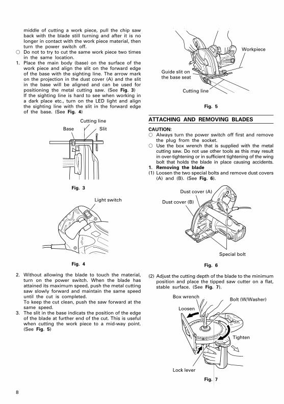
1. Place the main body (base) on the surface of thework piece and align the slit on the forward edgeof the base with the sighting line. The arrow markon the projection in the dust cover (A) and the slitin the base will be aligned and can be used forpositioning the metal cutting saw. (See Fig. 3)If the sighting line is hard to see when working ina dark place etc., turn on the LED light and alignthe sighting line with the slit in the forward edgeof the base. (See Fig. 4)
Fig. 3
Fig. 4
2. Without allowing the blade to touch the material,turn on the power switch. When the blade hasattained its maximum speed, push the metal cuttingsaw slowly forward and maintain the same speeduntil the cut is completed.To keep the cut clean, push the saw forward at thesame speed.
3. The slit in the base indicats the position of the edgeof the blade at further end of the cut. This is usefulwhen cutting the work piece to a mid-way point.(See Fig. 5)
Fig. 5
ATTACHING AND REMOVING BLADES
CAUTION:� Always turn the power switch off first and remove
the plug from the socket.� Use the box wrench that is supplied with the metal
cutting saw. Do not use other tools as this may resultin over-tightening or in sufficient tightening of the wingbolt that holds the blade in place causing accidents.
1. Removing the blade(1) Loosen the two special bolts and remove dust covers
(A) and (B). (See Fig. 6).
Fig. 6
(2) Adjust the cutting depth of the blade to the minimumposition and place the tipped saw cutter on a flat,stable surface. (See Fig. 7).
Fig. 7
Base
Cutting line
Slit
Light switch
Guide slit onthe base seat
Cutting line
Workpiece
Dust cover (A)
Dust cover (B)
Special bolt
Loosen
Lock lever
Box wrench Bolt (W/Washer)
Tighten
01Eng_CD7SA_Eng 5/15/09, 15:208
9
(3) While pushing in the lock lever, slowly unscrew thebolt using the box wrench provided.
(4) Holding the spindle in position, turn the box wrenchcounter-clockwise and remove the bolt and thewasher (B).
(5) Remove the tipped saw blade in direction (A).2. Attaching the bladeCAUTION:� After using the tipped saw blade, dust covers (A)
and (B) may become hot. Take caution whenhandling.
� Do not forget to use the distance piece.� Before plugging in the metal cutting saw, be sure
to check to see whether the lock lever has beenreturned to its original position and that the tippedsaw blade can rotate smoothly.
(1) Follow the blade removal routine in reverse.(2) Remove any cutting dust that may have adhered
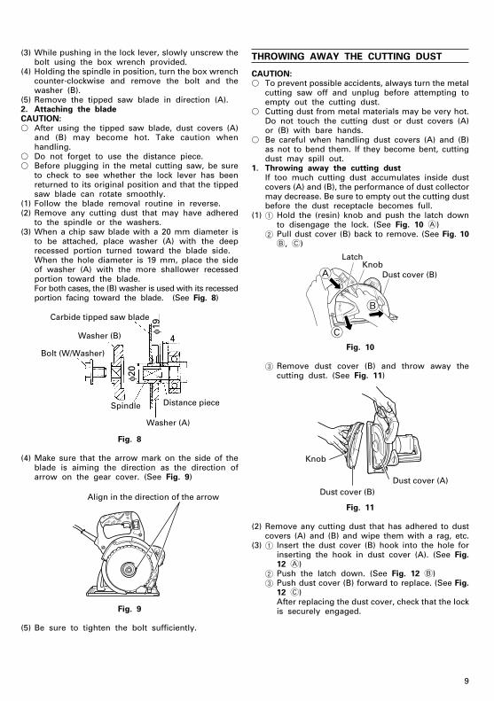
to the spindle or the washers.(3) When a chip saw blade with a 20 mm diameter is
to be attached, place washer (A) with the deeprecessed portion turned toward the blade side.When the hole diameter is 19 mm, place the sideof washer (A) with the more shallower recessedportion toward the blade.For both cases, the (B) washer is used with its recessedportion facing toward the blade. (See Fig. 8)
Fig. 8
(4) Make sure that the arrow mark on the side of theblade is aiming the direction as the direction ofarrow on the gear cover. (See Fig. 9)
Fig. 9
(5) Be sure to tighten the bolt sufficiently.
THROWING AWAY THE CUTTING DUST
CAUTION:� To prevent possible accidents, always turn the metal
cutting saw off and unplug before attempting toempty out the cutting dust.
� Cutting dust from metal materials may be very hot.Do not touch the cutting dust or dust covers (A)or (B) with bare hands.
� Be careful when handling dust covers (A) and (B)as not to bend them. If they become bent, cuttingdust may spill out.
1. Throwing away the cutting dustIf too much cutting dust accumulates inside dustcovers (A) and (B), the performance of dust collectormay decrease. Be sure to empty out the cutting dustbefore the dust receptacle becomes full.
(1) 1 Hold the (resin) knob and push the latch downto disengage the lock. (See Fig. 10 A)
2 Pull dust cover (B) back to remove. (See Fig. 10B, C)
Fig. 10
3 Remove dust cover (B) and throw away thecutting dust. (See Fig. 11)
Fig. 11
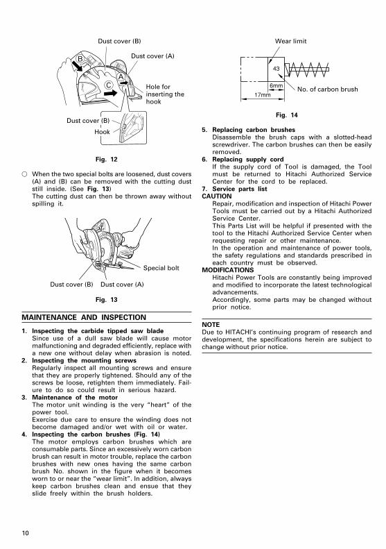
(2) Remove any cutting dust that has adhered to dustcovers (A) and (B) and wipe them with a rag, etc.
(3) 1 Insert the dust cover (B) hook into the hole forinserting the hook in dust cover (A). (See Fig.12 A)
2 Push the latch down. (See Fig. 12 B)3 Push dust cover (B) forward to replace. (See Fig.
12 C)After replacing the dust cover, check that the lockis securely engaged.
Washer (B)
Bolt (W/Washer)
Carbide tipped saw blade
Align in the direction of the arrow
A
C
B
Dust cover (B)
LatchKnob
Knob
Dust cover (B)Dust cover (A)
4
φ20
φ19
Spindle Distance piece
Washer (A)
01Eng_CD7SA_Eng 5/15/09, 15:209
10
Fig. 12
� When the two special bolts are loosened, dust covers(A) and (B) can be removed with the cutting duststill inside. (See Fig. 13)The cutting dust can then be thrown away withoutspilling it.
Fig. 13
MAINTENANCE AND INSPECTION
1. Inspecting the carbide tipped saw bladeSince use of a dull saw blade will cause motormalfunctioning and degraded efficiently, replace witha new one without delay when abrasion is noted.
2. Inspecting the mounting screwsRegularly inspect all mounting screws and ensurethat they are properly tightened. Should any of thescrews be loose, retighten them immediately. Fail-ure to do so could result in serious hazard.
3. Maintenance of the motorThe motor unit winding is the very “heart” of thepower tool.Exercise due care to ensure the winding does notbecome damaged and/or wet with oil or water.
4. Inspecting the carbon brushes (Fig. 14)The motor employs carbon brushes which areconsumable parts. Since an excessively worn carbonbrush can result in motor trouble, replace the carbonbrushes with new ones having the same carbonbrush No. shown in the figure when it becomesworn to or near the “wear limit”. In addition, alwayskeep carbon brushes clean and ensue that theyslide freely within the brush holders.
Fig. 14
5. Replacing carbon brushesDisassemble the brush caps with a slotted-headscrewdriver. The carbon brushes can then be easilyremoved.
6. Replacing supply cordIf the supply cord of Tool is damaged, the Toolmust be returned to Hitachi Authorized ServiceCenter for the cord to be replaced.
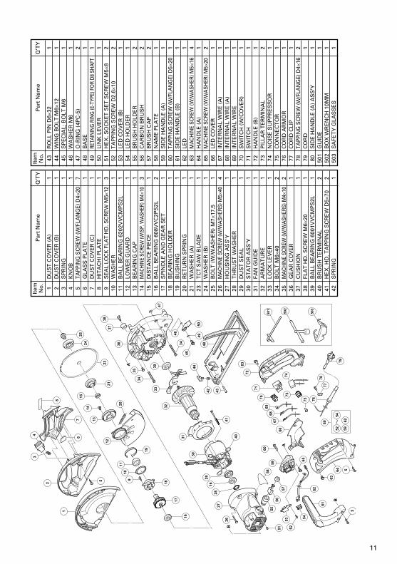
7. Service parts listCAUTION
Repair, modification and inspection of Hitachi PowerTools must be carried out by a Hitachi AuthorizedService Center.This Parts List will be helpful if presented with thetool to the Hitachi Authorized Service Center whenrequesting repair or other maintenance.In the operation and maintenance of power tools,the safety regulations and standards prescribed ineach country must be observed.
MODIFICATIONSHitachi Power Tools are constantly being improvedand modified to incorporate the latest technologicaladvancements.Accordingly, some parts may be changed withoutprior notice.
NOTEDue to HITACHI’s continuing program of research anddevelopment, the specifications herein are subject tochange without prior notice.
AC
B
Dust cover (B)
Dust cover (A)
Hole forinserting thehook
Dust cover (B)
Hook
Dust cover (B) Dust cover (A)
Special bolt
17mm
6mm
43
Wear limit
No. of carbon brush
01Eng_CD7SA_Eng 5/15/09, 15:2010
11
Item No
.P
art
Nam
eQ
’TY
1D
US
T C
OV
ER
(A
)1
2D
US
T C
OV
ER
(B
)1
3S
PR
ING
14
KN
OB
15
TAPP
ING
SC
REW
(W/F
LAN
GE)
D4×
207
6G
LAS
S P
LAT
E1
7D
US
T C
OV
ER
(C
)1
8H
ITA
CH
I PLA
TE
19
SEA
L LO
CK
FLA
T H
D. S
CR
EW M
5×12
310
WA
SH
ER
111
BA
LL B
EA
RIN
G 6
202V
VC
MP
S2L
112
LOW
ER
GU
AR
D1
13B
EA
RIN
G C
AP
114
MAC
HIN
E SC
REW
(W/S
P. W
ASHE
R) M
4×10
315
DIS
TA
NC
E P
IEC
E1
16B
ALL
BE
AR
ING
608
VV
C2P
S2L
217
SP
IND
LE A
ND
GE
AR
SE
T1
18B
EA
RIN
G H
OLD
ER
119
BU
SH
ING
120
RE
TU
RN
SP
RIN
G1
21W
AS
HE
R (
A)
123
TC
T S
AW
BLA
DE
124
WA
SH
ER
(B
)1
25B
OLT
(W
/WA
SH
ER
) M
7 ×17
.51
26M
ACH
INE
SCRE
W (W
/WA
SHER
S) M
5 ×40
427
HO
US
ING
AS
S'Y
128
TH
RU
ST
WA
SH
ER
129
DU
ST
SE
AL
130
ST
AT
OR
AS
S'Y
131
FAN
GU
IDE
132
AR
MA
TU
RE
133
LOC
K L
EV
ER
134
BO
LT M
6×40
235
MA
CHIN
E SC
REW
(W/W
ASH
ERS)
M4 ×
102
36G
EA
R C
OV
ER
137
CU
SH
ION
138
FLA
T H
D. S
CR
EW
M6×
201
39B
ALL
BE
AR
ING
600
1VV
CM
PS
2L1
40B
RU
SH
TE
RM
INA
L2
41H
EX
. HD
. TA
PP
ING
SC
RE
W D
5×70
242
SP
RIN
G1
Item No
.P
art
Nam
eQ
’TY
43R
OLL
PIN
D6×
321
44W
ING
BO
LT M
6×12
145
SP
EC
IAL;
BO
LT M
61
46W
AS
HE
R M
61
47O
-RIN
G (
4PC
-5)
248
BA
SE
149
RETA
ININ
G R
ING
(E-T
YPE)
FO
R D8
SHA
FT1
50LI
NK
LE
VE
R1
51H
EX
. SO
CK
ET
SE
T S
CR
EW
M5×
82
52T
AP
PIN
G S
CR
EW
D2.
6×10
253
LED
CO
VE
R (
B)
154
LED
HO
LDE
R1
55B
RU
SH
HO
LDE
R2
56C
AR
BO
N B
RU
SH
257
BR
US
H C
AP
258
NA
ME
PLA
TE
159
SID
E H
AN
DLE
(A
)1
60TA
PPIN
G S
CR
EW (W
/FLA
NG
E) D
5×20
161
SID
E H
AN
DLE
(B
)1
62LE
D1
63M
ACH
INE
SCRE
W (W
/WA
SHER
) M5×
164
64H
AN
DLE
(A
)1
65M
ACH
INE
SCRE
W (W
/WA
SHER
) M5 ×
202
66LE
D C
OV
ER
167
INT
ER
NA
L W
IRE
(A
)1
68IN
TE
RN
AL
WIR
E (
A)
169
INT
ER
NA
L W
IRE
170
SW
ITC
H (
W/C
OV
ER
)1
71S
WIT
CH
172
HA
ND
LE (
B)
173
PIL
LAR
TE
RM
INA
L2
74N
OIS
E S
UP
PR
ES
SO
R1
75C
ON
NE
CT
OR
176
CO
RD
AR
MO
R1
77C
OR
D C
LIP
178
TAPP
ING
SC
REW
(W/F
LAN
GE)
D4×
162
79C
OR
D1
80S
IDE
HA
ND
LE (
A)
AS
S'Y
150
1G
UID
E1
502
BO
X W
RE
NC
H 1
0MM
150
3S
AFE
TY
GLA
SS
ES
1
02Back_CD7SA_Eng 5/15/09, 15:2111

906Code No. C99167511 FPrinted in China
Hitachi Koki Co., Ltd.Shinagawa Intercity Tower A, 15-1, Konan 2-chome,
Minato-ku, Tokyo, Japan
02Back_CD7SA_Eng 5/15/09, 15:2112