Embed Size (px)
Citation preview

METAL CUTTING BAND SAW MACHINE
MODEL 128
INSTRUCTION MANUAL
128-061214-R4

WARNING! !
Some dust created by power sanding, sawing,
grinding, drilling, and other construction activities contains chemicals known to the State of California to cause cancer, birth defects or other reprodrctive harm. Some examples of these chemical are: ‧Lead from lead-based paints. ‧Crystalline silica from bricks, cement and other masonry products. ‧Arsenic and chromium from chemically-treated lumber. Your risk from these exposures varies, depending on how often you do this type of work. To reduce your exposure to these chemicals: Work in a well ventilated area, and word with approved safety equipment, such as those dust masks that are specially designed to filter out microscopic particles.

"THIS MACHINE 1S FOR METAL CUTTING ONLY, IT 1S NOT APPROVED FOR CUTTING WOOD.THE SUPPLIER ACCEPTS NO RESPONSIBILITY FOR ANY MACHINE WHEN USED FOR CUTTING WOOD. "
A. Average Noise Level=continuous level of airborne noise from machines when
running at full speed with no load. C. Loudest Noise level=the peak noise level recorded from machines when running
at full speed with no load. Based on above two measurements A & C. this band-saw's equivalent A-weighted sound pressure level at the work station was measured at 70 dB, while its peak C-weighted instantaneous sound pressure value at the work station was measured at 75 dB.
( FOR CE MACHINE ONLY ) CAUTION : VERTICAL CUTTING IS PROHIBITED IN THE MACHINE. NO VERTICAL CUTTING PLATE PROVIDED, TO PREVENT ANY IMPROPER USE.
- - 1

Table Of Contents Page No 1 Overall Aspect .......................................................................................................... 4 2 Safety rules for all tools ............................................................................................. 5 3 Specification .............................................................................................................. 8 4 Features ................................................................................................................... 8 5 Delivery & Installation .............................................................................................. 8 6 Minimum Room Space For Machine Operation ................................................... 11 7 Operation .................................................................................................................. 11 8 Machine elements adjustment .................................................................................. 14 9 Maintaining ................................................................................................................ 16 10 Lubricating ................................................................................................................. 16 11 Trouble Shooting ...................................................................................................... 17 12 Circuit Diagram ......................................................................................................... 19 13 Parts Drawing ........................................................................................................... 21 14 Parts List ................................................................................................................... 26
- - 2

1.Overall Aspect
BLADE TENSION WHEEL
BODY FRAME
BELT COVERPOWER ON/OFF
MOTOR
BASE FRAMEWORK
DISTANCE SET ROD
- - 3
WARNING: FAILURE TO FOLLOW THESE RULES MAY RESULT IN SERIOUS PERSONAL INJURY
As with all machinery there are certain hazards involved with operation and use of the machine. Using the machine with respect and caution will considerably lessen the possibility of personal injury. However, if normal safety precautions are overlooked or ignored, personal injury to the operator may result. This machine was designed for certain applications only. We strongly recommend that this machine NOT be modified and/or used for any application other than for which it was designed. If you have any questions relative to its application DO NOT use the machine until you contact with us and we have advised you. Your machine might not come with a power socket or plug. Before using this machine, please Do ask your local dealer to install the socket or plug on the power cable end. 2.SAFETY RULES FOR ALL TOOLS A. USER:
(1). WEAR PROPER APPAREL. No loose clothing, gloves, rings, bracelets, or other jewelry to get caught in moving parts. Non-slip foot wear is recommended. Wear protective hair covering to contain long hair. (2). ALWAYS WEAR EYE PROTECTION. Refer to ANSLZ87.1 standard for appropriate
recommendations. Also use face or dust mask if cutting operation is dusty. (3). DON'T OVERREACH. Keep proper footing and balance at all times. (4). NEVER STAND ON TOOL. Serious injury could occur if the tool is tipped or if the
cutting tool is accidentally contacted. (5). NEVER LEAVE TOOL RUNNING UNATTENDED. TURN POWER OFF. Don't leave
tool until it comes to a complete stop. (6). DRUGS, ALCOHOL, MEDICATION. Do not operate tool while under the influence of
drug, alcohol or any medication. (7). MAKE SURE TOOL IS DISCONNECTED FROM POWER SUPPLY. While motor is
being mounted, connected or reconnected. (8). ALWAYS keep hands and fingers away from the blade. (9). STOP the machine before removing chips. (10). SHUT- OFF power and clean the BAND SAW and work area before leaving the machine.
B. USE OF MACHINE: (1). REMOVE ADJUSTING KEYS AND WRENCHES. Form habit of checking to see that
- - 4

keys and adjusting wrenches are removed from tool before turning it "on". (2). DON'T FORCE TOOL. It will do the job better and be safer at the rate for which it was
designed. (3). USE RIGHT TOOL. Don't force tool or attachment to do a job for which it was not
designed. (4). SECURE WORK. Use clamps or a vise to hold work when practical. It's safer than using
your hand frees both hands to operate tool. (5). MAINTAIN TOOLS IN TOP CONDITION. Keep tools sharp and clean for best and safest
performance. Follow instructions for lubricating and changing accessories. (6). USE RECOMMENDED ACCESSORIES. Consult the owner's manual for recommended
accessories. The use of improper accessories may cause hazards. (7). AVOID ACCIDENTAL STARTING. Make sure switch is in “OFF” position before
plugging in power cord. (8). DIRECTIONOF FEED. Feed work into a blade or cutter against the direction of rotation of
the blade or cutter only. (9). ADJUST AND POSITION the blade guide arm before starting the cut. (10). KEEP BLADE GUIDE ARM TIGHT, A loose blade guide arm all affect sawing
accuracy . (11). MAKE SURE blade speed is set correctly for material being cut. (12). CHECK for proper blade size and type. (13). STOP the machine before putting material in the vise. (14). ALWAYS have stock firmly clamped in vise before starting cut. (15). GROUNDALL TOOLS. If tool is equipped with three-prong plug, it should be plugged
into a three-hole electrical receptacle. If an adapter is used to accommodate two-prong receptacle, the adapter lug must be attached to a known ground. Never removed the third prong.
C. ADJUSTMENT :
MAKE all adjustments with the power off. In order to obtain the machine. precision and correct ways of adjustment while assembling, the user should read the detailed instruction in
this manual. D. WORKING ENVIRONMENT:
(1). KEEP WORK AREA CLEAN. Cluttered areas and benches invite accidents. (2). DON'T USE IN DANGEROUS ENVIRONMENT. Don't use power tools in damp or wet
locations, or expose them to rain. Keep work area well-lighted. (3). KEEP CHILEREN AND VISITIORS AWAY. All children and visitors should be kept a
safe distance from work area.
- - 5

(4). DON’T install & use this machine in explosive, dangerous environment.
E. MAINTENANCE: (1). DISCONNECT machine from power source when making repairs. (2). CHECK DAMAGED PARTS. Before further use of the tool, a guard or other part that is damaged should be carefully checked to ensure that it will operate properly and perform its
intended function check for alignment of moving parts, binding of moving parts, breakage of parts, mounting, and any other conditions that may affect its operation. A guard or other part that is damaged should be properly repaired or replaced.
(3). DISCONNECT TOOLS before servicing and when changing accessories such as blades, bits, cutters, etc.
(4). MAKE SURE that blade tension and blade tacking are properly adjusted. (5). RE-CHECK blade tension after initial cut with a new blade.
(6). TO RPOLONG BLADE LIFE ALWAYS release blade tension at the end of each work day.
(7).CHECK COOLANT DAILY Low coolant level can cause foaming and high blade temperatures. Dirty or week coolant can clog pump, cause crooked. Cust, low cutting rate and permanent blade failure. Dirty coolant can cause the growth of bacteria with ensuing skin irritation.
(8). WHEN CUTTING MAGNESIUM NEVER use soluble oils or emulsions(oil-water mix) as water will greatly intensify any accidental magnesium chip fire. See your industrial coolant supplier for specific coolant recommendations when cutting magnesium.
(9). TO PRNMT corrosion of machined surfaces when a soluble on is used as coolant, pay particular attention to wiping dry the surfaces where fluid accumulates and does not evaporate quickly, such as between the machine bed and vise.
F. SPECTIFIED USAGE: This machine is used only for general metals cutting within the range of cutting capacity. G. NOISE: A weighted sound pressure level : 80 dB.
- - 6

3.SPECIFICATIONS:
1. Capacity : 90°-- =Ø5” (Ø 128mm) -- = 4-1/2” * 6” (115mm * 150mm) : 45°-- =Ø3” (Ø 76mm) -- = 3” * 4-1/2” (76mm * 115mm) 2. Speeds : 60HZ = 80-120-200 FPM ( 24-37-61 M.P.M) : 50HZ = 65-95-165 FPM (20-29-50 M.P.M) 3. Motor : 1/3HP (1/2 HP) , 60HZ=1725RPM 50HZ=1420RPM 4. Blades Size( W * T * L) : 1/2” * 0.025” * 64 1/2” (12.7mm * 0.64mm * 1635mm) 5. Blade Wheels : 7 3/8”(187mm) High strength flanged cast iron. 6. Floor Model Dimensions : Length -(1029mm)
: Width -(457mm) : Height- (965mm) Cut/Off
: Height -(1378mm) Vertical 7. Bench Model Dimensions : Length -(1029mm)
: width -(457mm) : Height -(591mm) Cut/Off
: Height -(851mm) Vertical 8. N. W./G.W. : 60 / 61 Kgs 9. Packing (L * W * H) : 38” x 13” x 16”(965mmx330mmx406mm) 10. 20’ Container Q’ty : 249 sets(CE 190 sets)
4.FEATURES 1. Special designed horizontal band saw.
2. Offers three speeds for cutting metal. 3. Shuts off automatically when material is cut. 4. With scale for the mitering vise. 5. No noise while operating. 6. Casters (optional) quick and easy moving.
5.DELIVERY & INSTALLATION
5-1.Unpacking 1. Transportation to desired location before unpacking, please use lifting jack.(Fig. B)
- - 7

2. Transportation after unpacking, please use heavy duty fiber belt to lift up the machine.
Fig. B ALLWAYS KEEP PROPER FOOTING & BALANCE WHILE MOVING THIS MACHINE. TRANSPORTATION OF MACHINE: As this machine weights 60kgs(135lbs) it is recommended that the machine be transported with help of lifting jack. Transportation Recommendation: 1. Tighten all locks before operation. 2. ALWAYS Keep proper footing & balance while moving this machine, and only use heavy
duty fiber belt to lift the machine. 3. TURN OFF the power before wiring & be sure machine is properly grounded.
Overload & circuit breaker are recommended for safety wiring. 4.CHECK carefully if the saw is blade is running in counter-clockwise direction if not, reverse the wiring per cicuit diagram then repeat the running test. 5. KEEP machine always out from sun, dust, wet or raining area.
5.2.Band Saw Installation 1. The saw may be mounted on your own bench, or sand using six bolts.
2. The rear end of the base must be mounted on the rear of the stand or bench to permit vertical operation for this band saw.
3. KEEP machine always out from sun, dust, wet, mining area . 4. CHECK carefully if the saw blade is running in counter-clockwise direction if not, reverse
the wiring per circuit diagram then repeat the running test.
- - 8

- - 9
5. Tighten all locks before operation.
- - 9

6.MINIMUM ROOM SPACE FOR MACHINE OPERATION
78”
55”
80”
7. OPERATION
A. A Hexagon Head Screw should be adjusted in accurate height when machine in cutting and after finished off cutting then magnetic Switch can be lost.
7-1. Operation Steps (1) Raise the saw head to vertical position. (2) Adjust the motor automatic stop key so the motor might stop just
while the work-piece is cut off. (3) Adjust the stock stop to the desired length position. (4) Open vise to accept the work-piece to be cut. If the piece is long, support the end. (5) Rotate the hand wheel to tighten the work-piece. (6) Turn on the switch, and change the blade speed to best suit the work-piece being cut. (7) Let the saw head down slowly to touch the work-piece lest the blade should be broken by
excessive pressure. (8) Rotate the adjusting rod to obtain the proper pressure.
7-2. Helpful Cutting Hints (1) The harder the materials, the slower the cutting speed should be.
- - 10

(2) Use of cutting oil is recommended when the blade speed is higher. (3) To increase the feed, turn the feed screw adjustment (at left of base) counter clockwise: to
decrease turn clockwise. Do not adjust more than one turn at a time. 7-3. Blade Speeds
When using your band saw always change the blade speed to best suit the material being cut. The material cutting chart gives suggested setting for several materials.
MATERIAL CUTTING CHART
Speed Belt Groove Used
Material 50Hz 60Hz Motor Pulley Saw Pulley
Tool, Stainless or Alloy Steel, Bearing Bronzes
20 MPM 24 MPM Small Large
Mild Steel, Hard Brass or Bronze
29 MPM 37 MPM Medium Medium
Soft Brass, Aluminum, other light materials
50 MPM 61 MPM Large Small
7-4. Blade selection (1) A 14-tooth per inch, general-use blade is furnished with this metal cutting band saw.
Additional blades in 6, 10. 14 and 18 tooth sizes are available. (2) The choice of blade pitch is governed by the thickness of the work to be cut. (3) The thinner work-piece. The more teeth advised. (4) If the teeth of the blade are too far apart can result in severe damage to the work-piece and to
the blade. 7-5. Changing blades Raise saw head to vertical position. Loosen blade tension adjustable knob sufficiently to allow the saw blade to slip off the wheels. Install the new blade as follows: (1) Place the blade in between each of guide bearing. (2) Slip the blade around the motor pulley (bottom) with the left hand and hold in position. (3) Hold the blade taut against the motor pulley by pulling the blade upward with the right hand
which be placed at the top of the blade. (4) Remove left hand from bottom pulley and place it at the top side of the blade to continue the
application on the upward pull on the blade.
- - 11

(5) Remove right hand from blade and adjust the position of the top pulley to permit left hand to slip the blade around the pulley using the thumb, index and little finger as guides.
(6) Adjust the blade tension knob clockwise until it is just right enough, so no blade slippage occurs. Do not tighten excessively.
(7) Place 2-3 drops of oil on the blade. (8) Replace the blade guard.
7-6. Starting Saw (1) Never operate saw without blade guards in place. (2) Be sure the blade is not in contact with the work when the motor is started. (3) Start the motor, allow the saw to come to full speed. (4) Do not drop or force the head provide the cutting force by letting the head down slowly into
the work. (5) Proper feed is important, excessive pressure can break the blade or stall the saw. Insufficient
pressure dulls the blade rapidly. (6) Never use a new blade to complete previously started cut. (7) Do not start cutting on the sharp corners.
Switch button function description A Stop button B Start button ON-OFF Switch Toggle Switch 7-7.TELLTALE CHIPS
Chips are the best indicator of correct feed force. Monitor chip information and adjust feed accordingly. Thin or powdered chips – increase feed rate or reduce band speed. Burned heavy chips – reduce feed rate and/or band speed.
Curly silvery and warm chips – optimum feed rate and band speed.
- - 12

8. MACHINE ELEMENTS ADJUSTMENT
8-1. Vertical Adjustment of the Blade Wheels (1) Remove the blade guards. (2) Turn the blade tension adjustable knob counterclockwise so that the blade might loosen a
little. (3) Adjust the hex-hole screw in the hole of slide block until the front blade wheel rises
backward a little so that the blade will be kept in position. (4) Tighten the blade tension adjustable knob until the blade obtains the proper tension. (5) Check the tracking by turning on the machine. If the blade slides forward, go back to step 4
until the rear blade touches the flange of blade wheel. (6) Turn off power to the machine. (7) Replace the blade guards. 8-2. Blade Guide Bearing Adjustment Attention: This is the most important adjustment on your saw. It is impossible to get satisfactory work from your saw if the blade guides are not properly adjusted. Note: There should be from .000 (just touching) .001 clearance between the blade and guide bearing. To obtain this clearance adjust as follows: (1) Each of two guide bearing is mounted to an eccentric bushing and can be adjusted. (2) Loosen the nut while holding the bolt with an alien wrench. (3) Position the eccentric by turning the bolt to the desired position of clearance. (The blade
will be just completely vertical while it is cutting.) (4) Tighten the nut, and the adjustable shaft of the guide bearing is fixed. (5) Adjust the second blade guide bearing in the same manner.
8-3. Blade Tension Adjustment: (1) Make sure the motor is shut off. (2) Press the blade lightly with the left hand, make the rear blade against the flange of blade
wheel and feel the blade tension that the blade does not come off from the wheel. (3) Adjust the blade tension adjustable knob with the right hand until the blade obtains the
proper tension.
- - 13
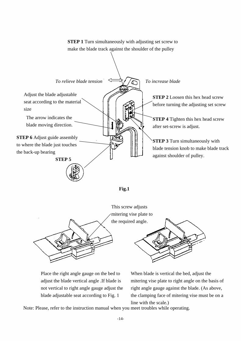
STEP 1 Turn simultaneously with adjusting set screw to
make the blade track against the shoulder of the pulley
STEP 2 Loosen this hex head screw before turning the adjusting set screw STEP 4 Tighten this hex head screw after set-screw is adjust. STEP 3 Turn simultaneously with blade tension knob to make blade track against shoulder of pulley.
STEP 6 Adjust guide assembly to where the blade just touches the back-up bearing
STEP 5
The arrow indicates the blade moving direction.
Adjust the blade adjustable seat according to the material size
To relieve blade tension To increase blade
Fig.1
This screw adjusts mitering vise plate to the required angle.
Place the right angle gauge on the bed to adjust the blade vertical angle .If blade is not vertical to right angle gauge adjust the blade adjustable seat according to Fig. 1
Note: Please, refer to the instruction manual when you meet troubles while operating.
When blade is vertical the bed, adjust the mitering vise plate to right angle on the basis of right angle gauge against the blade. (As above, the clamping face of mitering vise must be on a line with the scale.)
- - 14

64-9 64-1 64-10
Method of adjusting blade: A. Loosen the screw # 64-10. B. Adjust the blade adjustable seat # 64-1 to make the blade vertical to bed. C. Place the square on the bed to check if the blade is vertical, if not, repeat the process A to C. D. Tighten the screw # 64-10. 9. MAINTAINING That's easier to keep machine in good condition or best performance by means of maintaining it at any time than remedy it after it is out of order.
(1) Daily Maintenance (by operator) (a) Fill the lubricant before starting machine everyday. (b) If the temperature of spindle caused over-heating or strange noise, stop machine
immediately to cheek it for keeping accurate performance. (c) Keep work area clean; release vise, cutter, work-piece from table; switch off` power
source; take chip or dust away from machine and follow instructions lubrication or coating rust proof oil before leaving.
(2) Weekly Maintenance (a) Clean and coat the leading screw with oil.
(b) Check to see if sliding surface and turning parts lack of lubricant. If the lubricant is insufficient, fill it.
(3) Monthly Maintenance (a) Check if the fixed portion had been loose. (b) Lubricate bearing, worm, and worm shaft to avoid the wearing. (4) Yearly Maintenance (a) Adjust table to horizontal position for maintenance of accuracy. (b) Check electric cord, plug, switches, at least once a year to avoid loosening or wearing. 10. LUBRICATING (1) Be sure to clean. The band saw after operation. And coat this machine with rust-less oil.
- - 15

(2) Using SAE-30 oil to lubricate the components. (3) Lubricate the vise lead screw as heeded. (4) The drive gears are in oil bath, they will not require a lubricant change more often than once a year, unless a leak or over-heat occur. 11.TROUBLE SHOOTING Symptom Possible Cause(s) Corrective Action
Excessive Blade Breakage
1. Materials loosen in vise. 2. Incorrect speed or feed 3. Blade teeth spacing too large 4. Material too coarse 5. Incorrect blade tension 6.Teeth in contact with material
before saw is started 7. Blade rubs on wheel flange 8. Miss-aligned guide bearings 9. Blade too thick 10 Cracking at weld
1. Clamp work securely 2. Adjust speed or feed 3. Replace with a small teeth
spacing blade 4. Use a blade of slow speed
and small teeth spacing 5. Adjust to where blade just
does not slip on wheel 6. Place blade in contact
with work after motor is starred
7. Adjust wheel alignment 8. Adjust guide bearings 9. Use thinner blade 10. Weld again, note the weld
skill. Premature Blade Dulling
1. Teeth too coarse 2. Too much speed 3. Inadequate feed pressure 4.Hard spots or scale on material 5. Work hardening of material. 6.Blade twist 7. Insufficient blade 8. Blade slide
1. Use finer teeth 2. Decrease speed 3. Decrease spring tension on
side of saw 4. Reduce speed, increase feed
pressure 5. Increase feed pressure by
reducing spring tension 6. Replace with a new blade,
and adjust blade tension 7. Tighten blade tension
adjustable knob 8. Tighten blade tension
- - 16

Unusual Wear on Side/Back of Blade
1.Blade guides worn. 2.Blade guide bearings not adjust
properly 3.Blade guide bearing bracket is
loose
1.Replace. 2.Adjust as per operators
manual 3.Tighten.
Teeth Ripping from Blade.
1. Tooth too coarse for work 2. Too heavy pressure; too slow
speed. 3. Vibrating work-piece. 4. Gullets loading
1. Use finer tooth blade. 2. Decrease pressure, increase
speed 3. Clamp work piece securely 4. Use coarser tooth blade or
brush to remove chips. Motor running too hot 1. Blade tension too high.
2. Drive belt tension too high. 3. Blade is too coarse for work 4. Blade is too fine for work 5. Gears aligned improperly 6. Gears need lubrication 7. Cut is binding blade
1. Reduce tension on blade. 2. Reduce tension on drive belt.3. Use finer blade. 4. Use coarse blade. 5. Adjust gears so that worm is
in center of gear. 6. Check oil path. 7. Decrease reed anti speed
Bad Cuts (Crooked) 1. Feed pressure too great. 2. Guide bearings not adjusted
properly 3. Inadequate blade tension. 4. Dull blade. 5. Speed incorrect. 6. Blade guides spaced out too much7. Blade guide assembly loose 8. Blade truck too far away from wheel flanges
1. Reduce pressure by increasing spring tension on side of saw
2. Adjust guide bearing, the clearance can not greater than 0.001.
3. Increase blade tension by adjust blade tension
4. Replace blade 5. Adjust speed 6. Adjust guides space. 7. Tighten 8. Re-track blade according to
operating instructions. Bad Cuts (Rough) 1. Too much speed or feed
2. Blade is too coarse 3. Blade tension loose
1. Decrease speed or feed. 2. Replace with finer blade. 3. Adjust blade tension.
Blade is twisting
1. Cut is binding blade. 2. Too much blade tension.
1. Decrease reed pressure. 2. Decrease blade tension.
- - 17

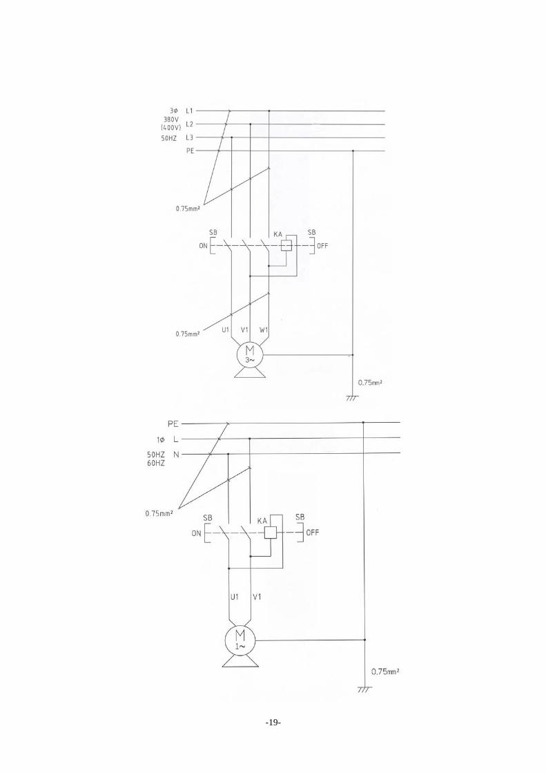
12.CIRCUIT DIAGRAM
- - 18
- - 19

-21-

-22-

-23-

-24-

-25-

-26-

CODE NO PART NO DESCRIPTION SPECIFICATION QTY NOTE
1 S022 Hex. Head Screw 5/16X3/4 4
2 N003 Hexagon Nut 1/4" 1
3 W005 Washer 1/4"x16xt1.5 1 FOR CE ONLY
4S2 3004FS Stand Complete Assembly 1
4-1 3004F-1 Cross Brace 2
4-2 3004F-2 Stand Leg 4
4-3 3004F-3 Leg 2
4-4 3004F-4 Leg 2
4-5 3206 Screw 5/16"x3/4"L 16
4-6 W016 Washer 5/16"x23xt2 16
4-7 N007 Hex. Nut 5/16" 16
4-8 S017 Hex. Head Screw 5/16"x1"L 6
4-9 W016 Washer 5/16"x23xt2 12
4-10 N007 Hex. Nut 5/16" 6
4-11 32421E-3 Coaster of Stand 3/8" 4
6 N007 Hex. Nut 5/16" 4
15S 3015S Adjust Tension Rod 1
16 E158412 Motor Cable 1
17 3017 Pivoting Rod 1
18 W205 Spring Washer 5/16" 2
19 3019 Distance Set Bracket 1
20 S018 Hex. Head Screw 5/16"x5/16"L 1
21 3021 Stock Stop Rod ∮1/2"x216L 1
22 3022-1 Wire Relief Retainer 2
27 S017 Hex. Head Screw 5/16"x1"L 2
28 3028B Hand wheel 1
30 HE013 E Retaining Ring E10 1
31 S017 Hex. Head Screw 5/16"x1"L 1
32S 3032S Lead Screw 1
32-1 3032 Lead Screw 1
32-2 3033 Vise Nut 1
34 3034 Movable Vise Plate 1
35 W011 Washer 3/8"x27xt3 4
36 S013 Hex. Head Screw 3/8"x1-1/4"L 1
37 3037A Swivel Base 1
38 S708 Cross Round Head Screw 3/16"x3/8"L 2
39 3039B Scale 1
40 S708 Cross Round Head Screw 3/16"X3/8L 1
41 HE201 Wire Ring 1/2" 1
PARTS LIST
MODEL NO. 128
-26 -

CODE NO PART NO DESCRIPTION SPECIFICATION QTY NOTE
PARTS LIST
MODEL NO. 128
43 3043 Wire protector 1
44 Power cable 1
45 3045 Spring Handle Bracket 1
45-1 3045-1 Spring Handle Bracket 1
46 3046 Spring Adjusting Screw 1
47 3047 Spring 1
49 3049 Movable Vise Plate 1
50 S022 Hex. Head Screw 5/16"x3/4"L 4
51 W018 Washer 5/16"x23xt3 3
52 S019 Hex. Head Screw 5/16"x1-1/2"L 1
53 S001 Hex. Head Screw 7/16"x2"L 1 FOR CE ONLY
54 3054B Pivot 1
55S 3055AS Vertical Saw Table ( Optional) 1 FOR NON CE ONLY
55-1 S302 Flat Cross Head Screw 1/4"x3/8"L 1 FOR NON CE ONLY
55-2 3055A Vertical Saw Table ( Optional) 1 FOR NON CE ONLY
55-3 3056-2 Table Supporting Plate 1 FOR NON CE ONLY
55-4 N003 Hexagon nut 1/4" 1 FOR NON CE ONLY
58 3058 Plum handle Screw 1
59 3059B Blade Back Safety Cover 1
59-1 W005 Washer 1/4"×16t×1.5 2
59-2 S704 Cross Round Head Screw 1/4"×3/8"L 2
61 S609 Hex.Socket Headless Screw 5/16"x5/8"L 1
63S1 3064SA1 Blade Adjustable Assembly (Rear) 1
63-1 3064 Blade Adjustable (Rear) 1
63-2 3062 Bearing Shaft 1
63-3 3062-1 Guide Pivot (Right) 1
63-4 C100 C-Retainer Ring 2
63-5 CA6000ZZ Bearing 6000ZZ 3
63-6 3063 Bearing Pin ∮10x36L 1
63-7 N006 Hex. Nut 3/8"UNF 2
63-8 W204 Spring Washer ∮3/8" 2
63-9 3069 Deflector Plate 1
63-10 S302 Flat Cross Head Screw 1/4"x3/8"L 2
63-11 32405 Adjustable Bracket (Right) 1
63-12 S023 Hex. Head Screw 5/16"x1-1/4"L 1
63-13 W205 Spring Washer ∮5/16" 1
63-14 W016 Washer 5/16"x23xt2 1
64S1 3064SB1 Adjustable Bracket Assembly (Right) 1
64-1 3064-1 Blade Adjustable (Front) 1
-27 -

CODE NO PART NO DESCRIPTION SPECIFICATION QTY NOTE
PARTS LIST
MODEL NO. 128
64-2 3062 Bearing Shaft 1
64-3 3062-1 Guide Pivot (Left) 1
64-4 HCS01 C-Retainer Ring 2
64-5 CA6000ZZ Bearing 6000ZZ 3
64-6 3063 Bearing Pin ∮10x36L 1
64-7 N006 Hex. Nut 3/8"UNF 2
64-8 W204 Spring Washer ∮3/8" 2
64-9 32406 Adjustable Bracket (Left) 1
64-10 S023 Hex. Head Screw 5/16"x1-1/4"L 1
64-11 W205 Spring Washer ∮5/16" 1
64-12 W016 Washer 5/16"x23xt2 1
66 3066-3 Blade Adjustable Knob 3/8"-16UNCx31L 1
67 W205 Spring Washer 5/16" 2
69 S013 Hex. Head Screw 3/8"x1-1/4"L 1
71 3071 Blade Wheel (Front) 1
71-1 S610 Hex. Socker Headless Screw 5/16"x5/16"L 1
72 3072-2 Bearing Cover 2
73 K006 Key 5x5x25L 1
74 K008 Key 5x5x30L 1
75 S202 Hex. Head Screw 1/4"x5/8"L 4
76S2 3076-2S Switch Cut Off Tip(For CE Only) 1
76-1 3076-2 Switch Cut Off Tip(For CE Only) 1
76-2 N007 Hex. Nut 5/16" 1
76-3 S017 Hex. Head Screw 5/16"x1"L 1
76-4 S203 Hex. Head Screw 1/4"x3/8"L 1
76-5 W005 Washer 1/4"×16t×1.5 1
76S3 3076S Switch Cut Off Tip(For CE Only) 1
76-1 3076 Switch Cut Off Tip 1
76-2 W005 Washer 1/4"x16xt1.5 1
76-3 S202 Hex. Head Screw 1/4"x5/8"L 1
77S1 3077S Blade Wheel Assembly (Rear) 1
77-1 3077 Blade Wheel (Rear) 1
77-2S 3106S Blade Wheel Shaft Assembly 1
77-5 3099 Bushing 1
77S2 3077S-1 Blade Wheel Assembly (Rear) 1 OPTION
77-1 3077-1 Blade Wheel (Rear) 1 OPTION
77-2S 3106S Blade Wheel Shaft Assembly 1 OPTION
77-5 3119-1 Blade Wheel Bushing 1 OPTION
77-6 CA6202ZZ Ball Bearing (6202ZZ) 6202ZZ 2 OPTION
-28 -
CODE NO PART NO DESCRIPTION SPECIFICATION QTY NOTE
PARTS LIST
MODEL NO. 128
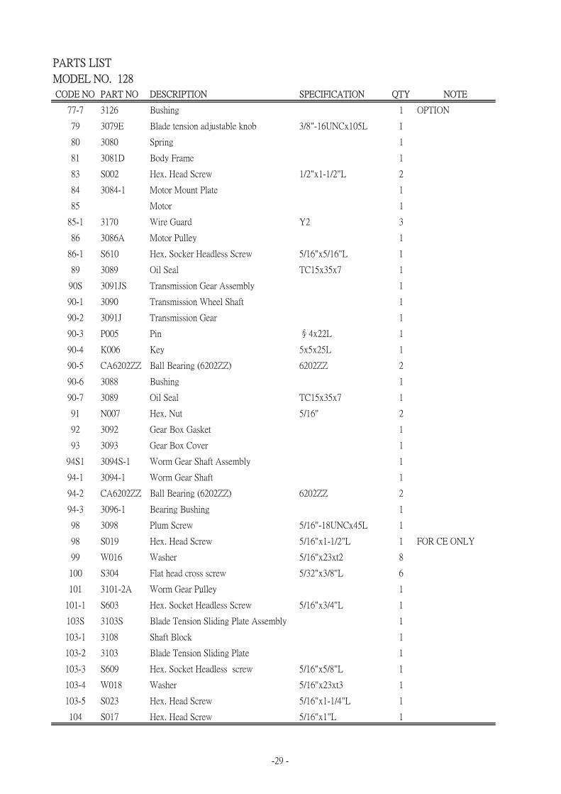
77-7 3126 Bushing 1 OPTION
79 3079E Blade tension adjustable knob 3/8"-16UNCx105L 1
80 3080 Spring 1
81 3081D Body Frame 1
83 S002 Hex. Head Screw 1/2"x1-1/2"L 2
84 3084-1 Motor Mount Plate 1
85 Motor 1
85-1 3170 Wire Guard Y2 3
86 3086A Motor Pulley 1
86-1 S610 Hex. Socker Headless Screw 5/16"x5/16"L 1
89 3089 Oil Seal TC15x35x7 1
90S 3091JS Transmission Gear Assembly 1
90-1 3090 Transmission Wheel Shaft 1
90-2 3091J Transmission Gear 1
90-3 P005 Pin ∮4x22L 1
90-4 K006 Key 5x5x25L 1
90-5 CA6202ZZ Ball Bearing (6202ZZ) 6202ZZ 2
90-6 3088 Bushing 1
90-7 3089 Oil Seal TC15x35x7 1
91 N007 Hex. Nut 5/16" 2
92 3092 Gear Box Gasket 1
93 3093 Gear Box Cover 1
94S1 3094S-1 Worm Gear Shaft Assembly 1
94-1 3094-1 Worm Gear Shaft 1
94-2 CA6202ZZ Ball Bearing (6202ZZ) 6202ZZ 2
94-3 3096-1 Bearing Bushing 1
98 3098 Plum Screw 5/16"-18UNCx45L 1
98 S019 Hex. Head Screw 5/16"x1-1/2"L 1 FOR CE ONLY
99 W016 Washer 5/16"x23xt2 8
100 S304 Flat head cross screw 5/32"x3/8"L 6
101 3101-2A Worm Gear Pulley 1
101-1 S603 Hex. Socket Headless Screw 5/16"x3/4"L 1
103S 3103S Blade Tension Sliding Plate Assembly 1
103-1 3108 Shaft Block 1
103-2 3103 Blade Tension Sliding Plate 1
103-3 S609 Hex. Socket Headless screw 5/16"x5/8"L 1
103-4 W018 Washer 5/16"x23xt3 1
103-5 S023 Hex. Head Screw 5/16"x1-1/4"L 1
104 S017 Hex. Head Screw 5/16"x1"L 1
-29 -

CODE NO PART NO DESCRIPTION SPECIFICATION QTY NOTE
PARTS LIST
MODEL NO. 128
109 3109 Blade Tension Sliding Guides 2
111 3111S-1 Motor Pulley Cover Assembly 1
112 3112B Belt 1
113 Blade 0.65x12.7x1638Lx14T 1
116 W005 Washer 1/4"x16xt1.5 2
118 S006 Hex. Head Screw 1/4"x1/2"L 2
120 3120 Bushing ∮19x∮17x7 2
122 N010 Hexagon nut 7/16" 1 FOR CE ONLY
123 S052 Hex. Head Screw 1/4"x1"L 1
132 3132 Safety Guard (Right) 1 FOR CE ONLY
133 3132-1 Safety Guard (Left) 1 FOR CE ONLY
134 S711 Cross Round Head Screw 5/32"x1/4"L 2 FOR CE ONLY
155 N004 Hex. Nut 3/16" 1
156 S708 Cross Round Head Screw 3/16"X3/8"L 1
157 W302 Star Washer 3/16" 2
158 N004 Hex. Nut 3/16" 1
159 S706 Cross Round Head Screw 3/16"x1/2"L 1
187 W018 Washer 5/16"x23xt3mm 1
188 N007 Hex. Nut 5/16" 1
189 W018 Washer 5/16"x23xt3 1
197 S009 Hex. Head Screw 1/4"x3/4"L 1 FOR CE ONLY
198 HCS04 C-Retainer ring S15 1
199 N003 Hexagon nut 1/4" 1 FOR CE ONLY
202 3134 Ring 1 FOR CE ONLY
203S ET1403S Toggle Switch 2P 1
203-1 ET1403 Toggle Switch 2P 1
203-2 3131B Switch Cover 1
203-3 Switch Indicator 1
203-4 3131A-2 Hex. Head Screw 2
203-6 S732 Cross Round Head Screw 3/16"x3/4"L 2
203-7 3041-1 Electric Cord Clip 1
207 32312 Position pin 1
208 32310 Plum handle 1
209 3172 Fixed Plste 1
210 S402 Hex. Socket Head Screw 1/4"x1/2"L 1
211 S204 Hex. Head Screw 1/4"x3/4"L 1
211-1 W015 Washer 5/16"x12xt2 1
212 S017 Hex. Head Screw 5/16"x1"L 2
214 S202 Hex. Head Screw 1/4"x5/8"L 4
-30 -

CODE NO PART NO DESCRIPTION SPECIFICATION QTY NOTE
PARTS LIST
MODEL NO. 128
215 HB812 Net 1/4" 1
224S2 3193DS Switch Base 1
224-1 S203 Cross Socker Hex. Head Screw 1/4"x3/8"L 2
224-2 W202 Star Washer 3/16" 2
224-3 3193D Switch Base 1
224-4 32408C Switch Base 1
224-5 HS514 Cross Round Head Screw M4x35L 1
226S ET1134S Push Switch 1 FOR CE ONLY
-31 -

MANUFACTURER: ADDRESS: SERIAL No.:
PLEASE WRITE DOWN THE SERIAL NO. ON THIS BLOCK FROM THE NAMEPLATE AFTER YOU RECEIVE THIS MACHINE.