Embed Size (px)
Citation preview

www.trajansawworks.com 128HD
Metal Cutting Band Saw
128HD INSTRUCTION MANUAL
“THIS MACHINE IS FOR METAL CUTTING ONLY, IT 1S NOT
APPROVED FOR CUTTING WOOD.”
1
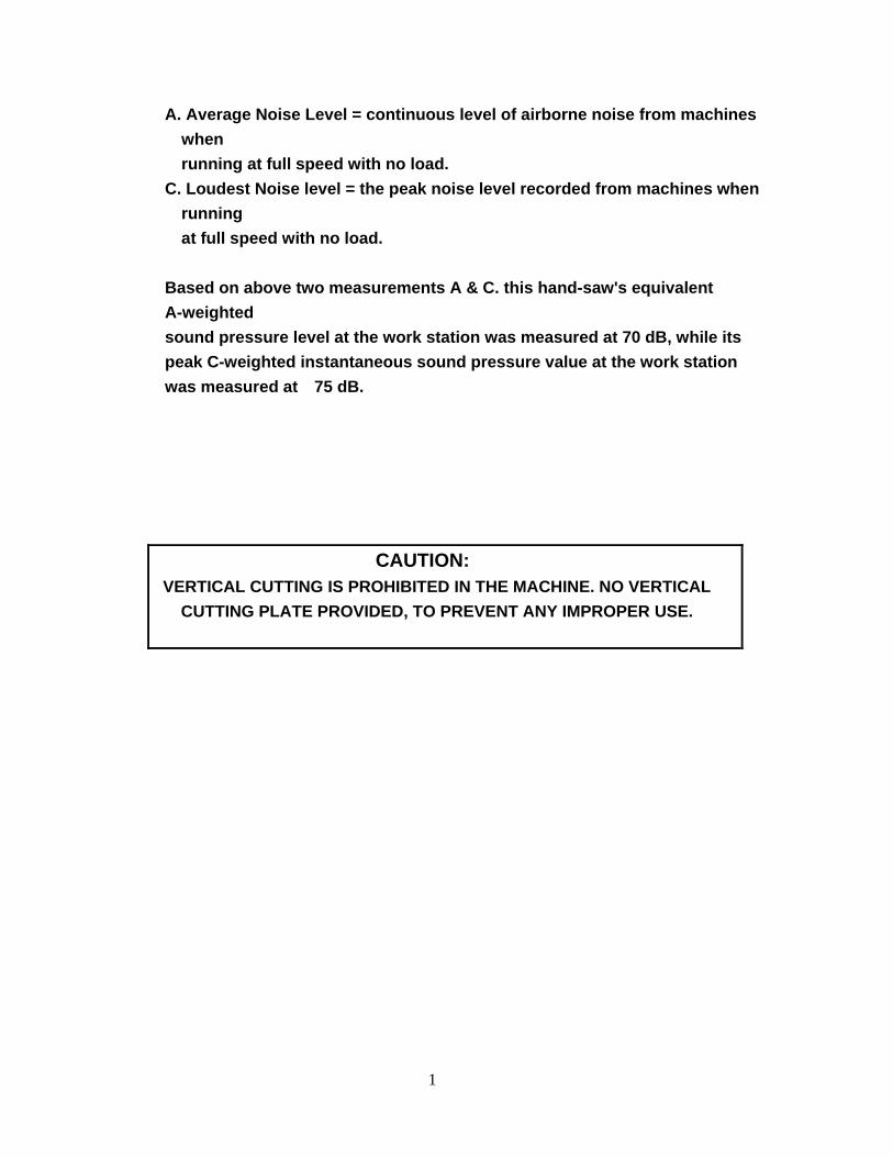
A. Average Noise Level = continuous level of airborne noise from machines when running at full speed with no load.
C. Loudest Noise level = the peak noise level recorded from machines when running at full speed with no load.
Based on above two measurements A & C. this hand-saw's equivalent A-weighted sound pressure level at the work station was measured at 70 dB, while its peak C-weighted instantaneous sound pressure value at the work station was measured at 75 dB.
CAUTION: VERTICAL CUTTING IS PROHIBITED IN THE MACHINE. NO VERTICAL
CUTTING PLATE PROVIDED, TO PREVENT ANY IMPROPER USE.
2
Table Of Contents
Manual Section Page Number
1 Overview……………………………………………………………………… ......3 2 Safety .............................................................................................................4 3 Specifications .................................................................................................8 4 Features .........................................................................................................8 5 Delivery & Installation.....................................................................................9 6 Minimum Room Space For Machine Operation.............................................9 7 Installation ....................................................................................................10 8 Operation......................................................................................................10 9 BI-Metal speeds and feeds...........................................................................11 10 Machine elements adjustment .....................................................................14 11 Maintinence..................................................................................................17 12 Cleaning & lubricating ..................................................................................17 13 Trouble Shooting..........................................................................................18 14 Electrical Diagram ....................................................................................... 20
WARNING: FAILURE TO FOLLOW THESE RULES MAY RESULT IN SERIOUS PERSONAL INJURY
As with all machinery there are certain hazards involved with operation and use of this machine. Proper use of the machine will considerably lessen the possibility of personal injury. If normal safety precautions are overlooked or ignored, personal injury to the operator may result. This machine was designed for specific applications only. We strongly recommend that this machine NOT be modified and/or used for any application other than for which it was designed. If you have any questions relative to applications DO NOT use the machine until you contact the manufacturer and they have advised you.
Before using this bandsaw, the proper electrical connections specific to this machine must be followed. Trajan Saw Works accepts no responsibility or liability
for damages or injuries caused by improper electrical components and/or connections
3
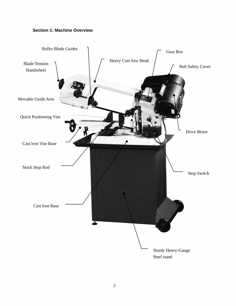
Section 1: Machine Overview
Blade Tension Handwheel
Roller Blade Guides
Belt Safety Cover
Gear Box
Drive Motor
Stop Switch
Cast Iron Base
Sturdy Heavy-Gauge Steel stand
Stock Stop Rod
Quick Positioning Vise
Movable Guide Arm
Cast lron Vise Base
Heavy Cast Saw Head
4
Section 2. Safety A) OPERATOR SAFETY:
1. WEAR PROPER APPAREL. Avoid loose fitting clothing, jewelry & gloves 2. ALWAYS WEAR EYE PROTECTION 3. NEVER LEAVE THE SAW RUNNING UNATTENDED. TURN POWER OFF. 4. DO NOT OPERATE THE SAW UNDER THE INFLUENCE OF DRUGS,
ALCOHOL, OR ANY PERSCRIPTION MEDICATION 5. ALWAYS KEEP HANDS AWAY FROM THE CUTTING AREA 6. STOP THE SAW BLADE BEFORE CLEANING CHIPS OUT OF THE PAN. 7. KEEP ALL GUARDS IN PLACE & IN WORKING ORDER.
B) ELECTRICAL SAFETY:
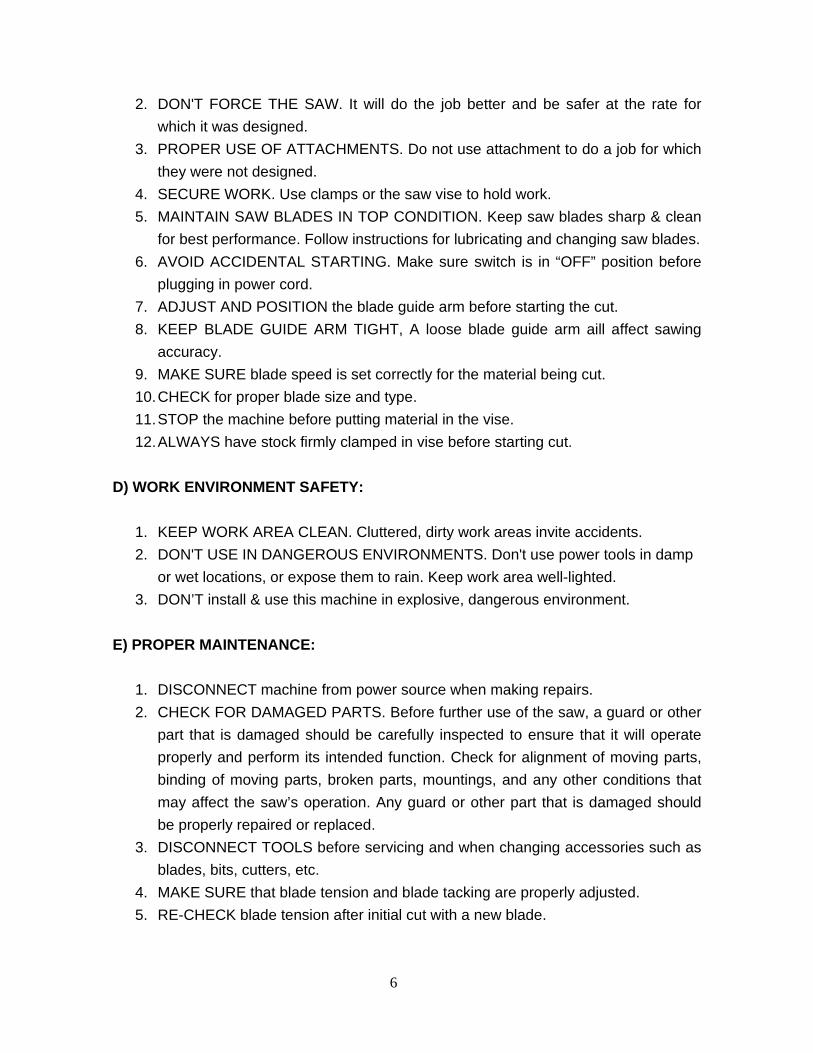
1. USE PROPERLY RATED POWER UL LISTED EXTENSION CORD Refer to table 72.1
2. LOCK OUT/TAG OUT To guard against unauthorized operation and avoid accidental starting by unauthorized personel, the use of a lock out padlock is suggested. To lock out the on-off switch, open the padlock, insert through the holes of the switch guard, and close the padlock . Place the key in a location that is inaccessible those not authorized to use the saw.
3. PROPER ELECTRICAL GROUND In the event of a malfunction or breakdown, grounding provides a path of least resistance for electric current to reduce the risk of electric shock . This saw is equipped with an electric cord having an equipment-grounding conductor and a grounding plug . The plug must be plugged into a matching outlet that is properly installed and grounded in accordance with all local codes and ordinances. Do not modify the plug provided. If it will not fit the outlet have the proper outlet Installed by a qualified electrician. Improper connection of the equipment-grounding conductor can result In a risk of electric shock.The conductor with insulation having an outer surface that is green with or without yellow stripes is the equipment-grounding conductor .If repair or replacement of the electric cord or plug is necessary do not connect the equipment-grounding conductor to a live terminal. Check with a qualified electrician or service personnel if the grounding instructions are not completely understood or if in doubt as to whether the tool is properly grounded. Use only
5
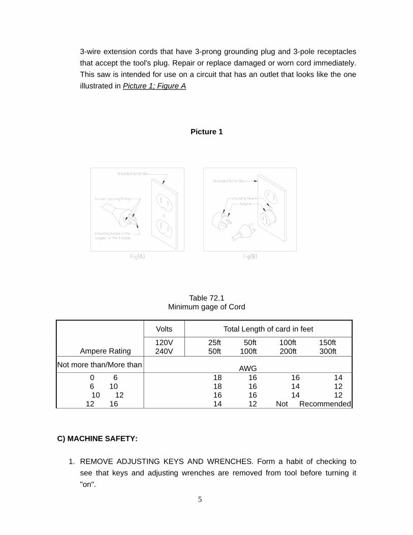
3-wire extension cords that have 3-prong grounding plug and 3-pole receptacles that accept the tool's plug. Repair or replace damaged or worn cord immediately. This saw is intended for use on a circuit that has an outlet that looks like the one illustrated in Picture 1; Figure A
Picture 1
Table 72.1 Minimum gage of Cord
Volts Total Length of card in feet
Ampere Rating 120V 240V
25ft 50ft 100ft 150ft 50ft 100ft 200ft 300ft
Not more than/More than AWG 0 6 6 10
10 12 12 16
18 16 16 14 18 16 14 12 16 16 14 12 14 12 Not Recommended
C) MACHINE SAFETY: 1. REMOVE ADJUSTING KEYS AND WRENCHES. Form a habit of checking to
see that keys and adjusting wrenches are removed from tool before turning it "on".
6
2. DON'T FORCE THE SAW. It will do the job better and be safer at the rate for which it was designed.
3. PROPER USE OF ATTACHMENTS. Do not use attachment to do a job for which they were not designed.
4. SECURE WORK. Use clamps or the saw vise to hold work. 5. MAINTAIN SAW BLADES IN TOP CONDITION. Keep saw blades sharp & clean
for best performance. Follow instructions for lubricating and changing saw blades. 6. AVOID ACCIDENTAL STARTING. Make sure switch is in “OFF” position before
plugging in power cord. 7. ADJUST AND POSITION the blade guide arm before starting the cut. 8. KEEP BLADE GUIDE ARM TIGHT, A loose blade guide arm aill affect sawing
accuracy. 9. MAKE SURE blade speed is set correctly for the material being cut. 10. CHECK for proper blade size and type. 11. STOP the machine before putting material in the vise. 12. ALWAYS have stock firmly clamped in vise before starting cut.
D) WORK ENVIRONMENT SAFETY: 1. KEEP WORK AREA CLEAN. Cluttered, dirty work areas invite accidents. 2. DON'T USE IN DANGEROUS ENVIRONMENTS. Don't use power tools in damp
or wet locations, or expose them to rain. Keep work area well-lighted. 3. DON’T install & use this machine in explosive, dangerous environment.
E) PROPER MAINTENANCE:
1. DISCONNECT machine from power source when making repairs. 2. CHECK FOR DAMAGED PARTS. Before further use of the saw, a guard or other
part that is damaged should be carefully inspected to ensure that it will operate properly and perform its intended function. Check for alignment of moving parts, binding of moving parts, broken parts, mountings, and any other conditions that may affect the saw’s operation. Any guard or other part that is damaged should be properly repaired or replaced.
3. DISCONNECT TOOLS before servicing and when changing accessories such as blades, bits, cutters, etc.
4. MAKE SURE that blade tension and blade tacking are properly adjusted. 5. RE-CHECK blade tension after initial cut with a new blade.
7
6. CHECK COOLANT DAILY Low coolant level can cause foaming and high blade
temperatures. Dirty or weak coolant can clog the pump, cause crooked cuts, rust, low cutting rate and permanent blade failure. Dirty coolant can cause the growth of bacteria with ensuing skin irritation.
7. WHEN CUTTING MAGNESIUM NEVER use soluble oils or emulsions(oil-water mix) as water will greatly intensify any accidental magnesium chip fire. See your industrial coolant supplier for specific coolant recommendations when cutting magnesium.
8. TO PREVENT CORROSION of machined surfaces when a soluble oil is used as coolant, pay particular attention to wiping dry the surfaces where fluid accumulates and does not evaporate quickly, such as between the machine bed and vise.
F) SPECIFIED USAGE:
1. This machine should be used only for general metal cutting within the range of cutting capacity..
H) SAFETY FEATURES:
1. Interlock switch on pulley cover. 2. As soon as the pulley cover is open, machine will stop with the function of this
switch. Do not remove this switch from machine for any reason, and check it's function frequently.
3. Interlock switch on cutting area as soon as the cover of cutting area is open, machine will stop at once witch the function of this switch. Do not remove this switch from machine for any reason, and check it's function frequently.
8
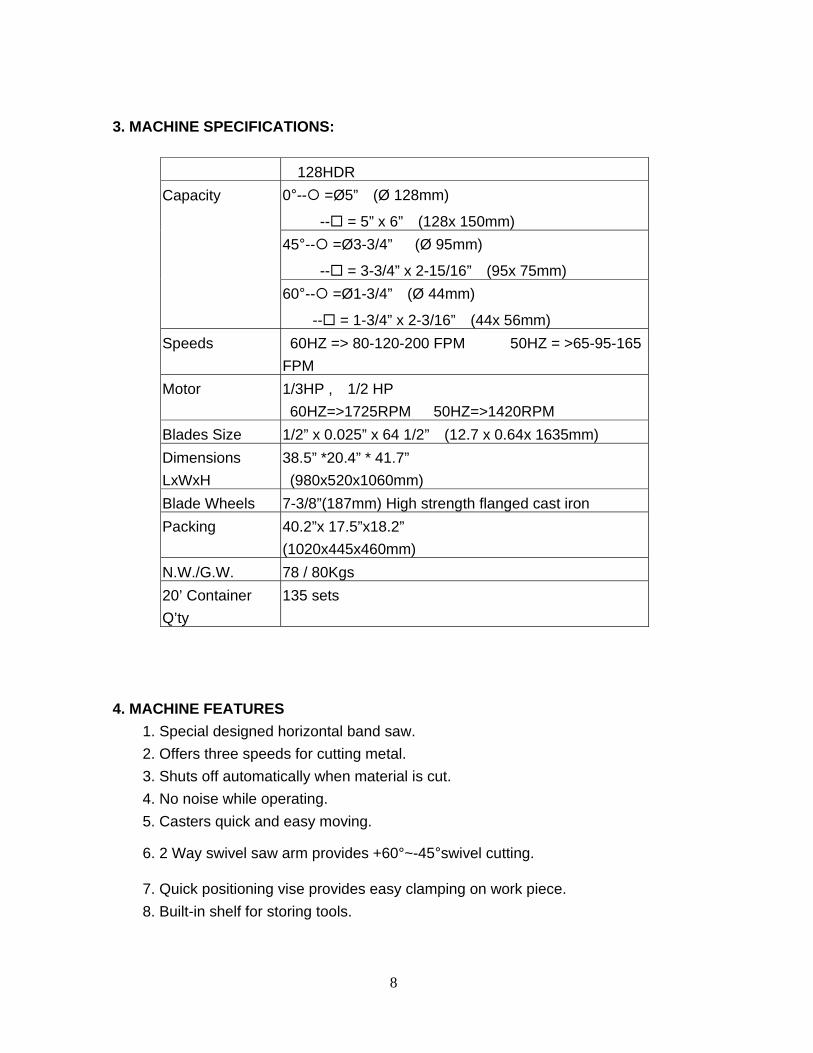
3. MACHINE SPECIFICATIONS:
128HDR 0°-- =Ø5” (Ø 128mm)
-- = 5” x 6” (128x 150mm) 45°-- =Ø3-3/4” (Ø 95mm)
-- = 3-3/4” x 2-15/16” (95x 75mm)
Capacity
60°-- =Ø1-3/4” (Ø 44mm)
-- = 1-3/4” x 2-3/16” (44x 56mm) Speeds 60HZ => 80-120-200 FPM 50HZ = >65-95-165
FPM Motor 1/3HP , 1/2 HP
60HZ=>1725RPM 50HZ=>1420RPM Blades Size 1/2” x 0.025” x 64 1/2” (12.7 x 0.64x 1635mm) Dimensions LxWxH
38.5” *20.4” * 41.7” (980x520x1060mm)
Blade Wheels 7-3/8”(187mm) High strength flanged cast iron Packing 40.2”x 17.5”x18.2”
(1020x445x460mm) N.W./G.W. 78 / 80Kgs 20’ Container Q’ty
135 sets
4. MACHINE FEATURES 1. Special designed horizontal band saw.
2. Offers three speeds for cutting metal. 3. Shuts off automatically when material is cut. 4. No noise while operating. 5. Casters quick and easy moving.
6. 2 Way swivel saw arm provides +60°~-45°swivel cutting.
7. Quick positioning vise provides easy clamping on work piece. 8. Built-in shelf for storing tools.
9
5. DELIVERY & INSTALLATION
3-1.Unpacking
1. Transport to desired location before unpacking 2. Transportation after unpacking, please use heavy duty fiber belt to lift up the
machine. 3. Finish removing this wooden case/crate from the machine. Unbolt the machine from
the crate bottom. Carefully lift the machine to a sturdy stand or work bench. For best performance, through .
Transportation Recommendations: 1. As this machine weights 78kgs(172lbs) it is recommended that the machine be
transported with help of lifting jack. 2. Tighten all locks before operation. 3. ALWAYS Keep proper footing & balance while moving this machine, and only use
heavy duty fiber belt to lift the machine. 3-2.Installation: 1. BE SURE all locks of head-stock & column are tighten before operation. 2. TURN OFF the power before wiring & be sure machine iS properly
grounded.Overload & circuit breaker is recommended for safety wiring. 3. CHECK carefully if main shaft in clockwise direction while running test. If not,
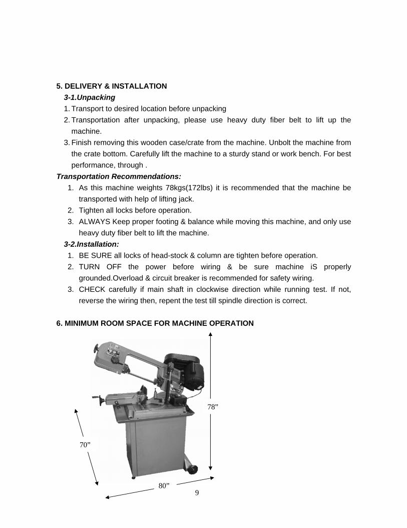
reverse the wiring then, repent the test till spindle direction is correct. 6. MINIMUM ROOM SPACE FOR MACHINE OPERATION
80”
70”
78”
10
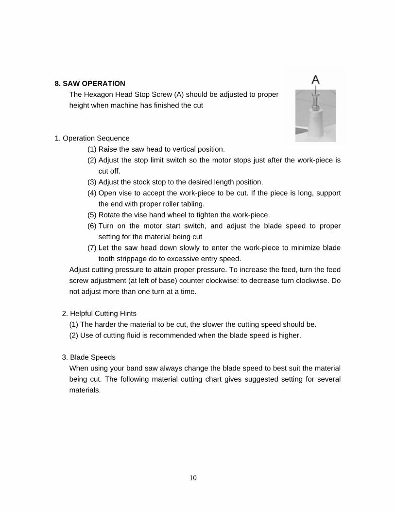
8. SAW OPERATION
The Hexagon Head Stop Screw (A) should be adjusted to proper height when machine has finished the cut
1. Operation Sequence
(1) Raise the saw head to vertical position. (2) Adjust the stop limit switch so the motor stops just after the work-piece is
cut off. (3) Adjust the stock stop to the desired length position. (4) Open vise to accept the work-piece to be cut. If the piece is long, support
the end with proper roller tabling. (5) Rotate the vise hand wheel to tighten the work-piece. (6) Turn on the motor start switch, and adjust the blade speed to proper
setting for the material being cut (7) Let the saw head down slowly to enter the work-piece to minimize blade
tooth strippage do to excessive entry speed. Adjust cutting pressure to attain proper pressure. To increase the feed, turn the feed screw adjustment (at left of base) counter clockwise: to decrease turn clockwise. Do not adjust more than one turn at a time.
2. Helpful Cutting Hints
(1) The harder the material to be cut, the slower the cutting speed should be. (2) Use of cutting fluid is recommended when the blade speed is higher.
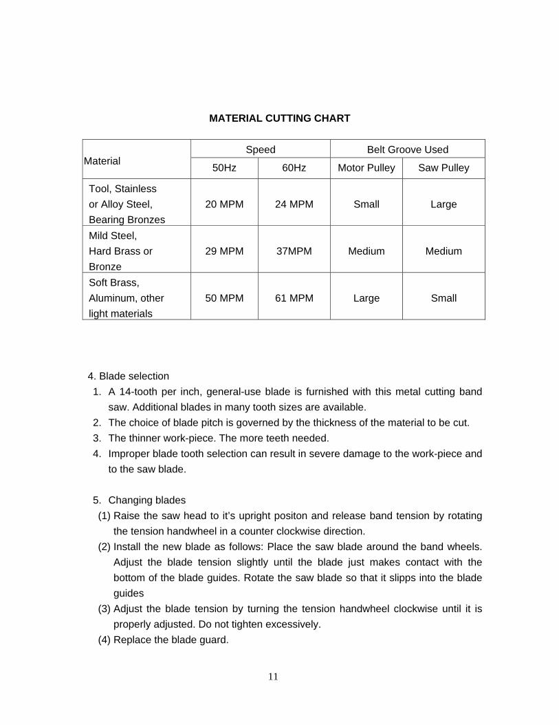
3. Blade Speeds
When using your band saw always change the blade speed to best suit the material being cut. The following material cutting chart gives suggested setting for several materials.
11
MATERIAL CUTTING CHART
Speed Belt Groove Used Material 50Hz 60Hz Motor Pulley Saw Pulley
Tool, Stainless or Alloy Steel, Bearing Bronzes
20 MPM 24 MPM Small Large
Mild Steel, Hard Brass or Bronze
29 MPM 37MPM Medium Medium
Soft Brass, Aluminum, other light materials
50 MPM 61 MPM Large Small
4. Blade selection 1. A 14-tooth per inch, general-use blade is furnished with this metal cutting band
saw. Additional blades in many tooth sizes are available. 2. The choice of blade pitch is governed by the thickness of the material to be cut. 3. The thinner work-piece. The more teeth needed. 4. Improper blade tooth selection can result in severe damage to the work-piece and
to the saw blade.
5. Changing blades (1) Raise the saw head to it’s upright positon and release band tension by rotating
the tension handwheel in a counter clockwise direction. (2) Install the new blade as follows: Place the saw blade around the band wheels.
Adjust the blade tension slightly until the blade just makes contact with the bottom of the blade guides. Rotate the saw blade so that it slipps into the blade guides
(3) Adjust the blade tension by turning the tension handwheel clockwise until it is properly adjusted. Do not tighten excessively.
(4) Replace the blade guard.
12
6. Starting Saw (1) Never operate saw without the blade guards in place. (2) Be sure the blade is not in contact with the work when the motor is started. (3) Start the motor and allow the saw to come to full speed before starting the cut. (4) Do not drop or force the head, let the saw provide the cutting force by the proper
setting of the cutting pressure. (5) Proper feed is important, excessive pressure can break the blade or stall the
saw. Insufficient pressure dulls the blade rapidly. (6) Never use a new blade to complete previously started cut. (7) Do not start cutting on the sharp corners.
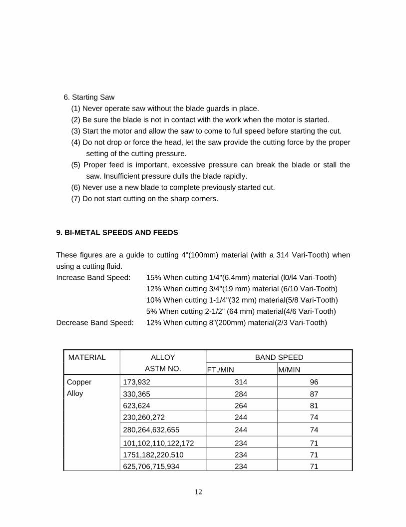
9. BI-METAL SPEEDS AND FEEDS These figures are a guide to cutting 4"(100mm) material (with a 314 Vari-Tooth) when using a cutting fluid. Increase Band Speed: 15% When cutting 1/4"(6.4mm) material (l0/l4 Vari-Tooth) 12% When cutting 3/4"(19 mm) material (6/10 Vari-Tooth) 10% When cutting 1-1/4"(32 mm) material(5/8 Vari-Tooth) 5% When cutting 2-1/2" (64 mm) material(4/6 Vari-Tooth) Decrease Band Speed: 12% When cutting 8"(200mm) material(2/3 Vari-Tooth)
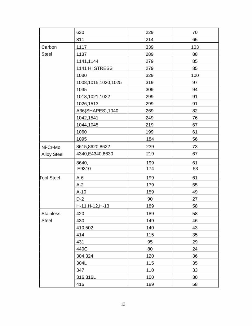
BAND SPEED MATERIAL ALLOY ASTM NO. FT./MIN M/MIN
173,932 314 96 330,365 284 87 623,624 264 81 230,260,272 244 74
280,264,632,655 244 74
101,102,110,122,172 234 71 1751,182,220,510 234 71
Copper Alloy
625,706,715,934 234 71
13
630 229 70 811 214 65 1117 339 103 1137 289 88 1141,1144 279 85 1141 HI STRESS 279 85 1030 329 100 1008,1015,1020,1025 319 97 1035 309 94 1018,1021,1022 299 91 1026,1513 299 91 A36(SHAPES),1040 269 82 1042,1541 249 76 1044,1045 219 67 1060 199 61
Carbon Steel
1095 184 56 8615,8620,8622 239 73 Ni-Cr-Mo
Alloy Steel 4340,E4340,8630 219 67
8640, 199 61 E9310 174 53
A-6 199 61 A-2 179 55 A-10 159 49 D-2 90 27
Tool Steel
H-11,H-12,H-13 189 58 420 189 58 430 149 46 410,502 140 43 414 115 35 431 95 29 440C 80 24 304,324 120 36 304L 115 35 347 110 33 316,316L 100 30
Stainless Steel
416 189 58
14
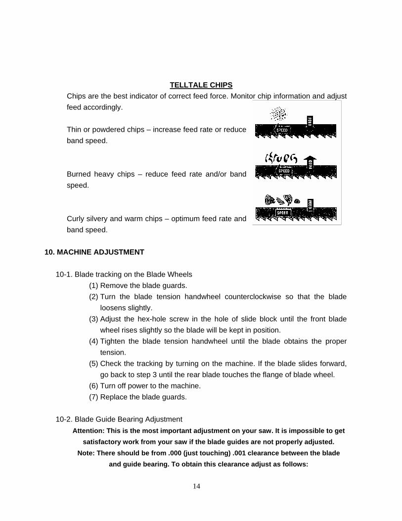
TELLTALE CHIPS Chips are the best indicator of correct feed force. Monitor chip information and adjust feed accordingly. Thin or powdered chips – increase feed rate or reduce band speed. Burned heavy chips – reduce feed rate and/or band speed. Curly silvery and warm chips – optimum feed rate and band speed.
10. MACHINE ADJUSTMENT 10-1. Blade tracking on the Blade Wheels
(1) Remove the blade guards. (2) Turn the blade tension handwheel counterclockwise so that the blade
loosens slightly. (3) Adjust the hex-hole screw in the hole of slide block until the front blade
wheel rises slightly so the blade will be kept in position. (4) Tighten the blade tension handwheel until the blade obtains the proper
tension. (5) Check the tracking by turning on the machine. If the blade slides forward,
go back to step 3 until the rear blade touches the flange of blade wheel. (6) Turn off power to the machine. (7) Replace the blade guards.
10-2. Blade Guide Bearing Adjustment
Attention: This is the most important adjustment on your saw. It is impossible to get satisfactory work from your saw if the blade guides are not properly adjusted.
Note: There should be from .000 (just touching) .001 clearance between the blade and guide bearing. To obtain this clearance adjust as follows:
15
(1) Each of two guide bearing is mounted to an eccentric bushing and can be adjusted.
(2) Loosen the nut while holding the bolt with an allen wrench. (3) Position the eccentric by turning the bolt to the desired position of
clearance. (The blade will be completely vertical when it is cutting.) (4) Tighten the nut (5) Adjust the second blade guide bearing in the same manner.
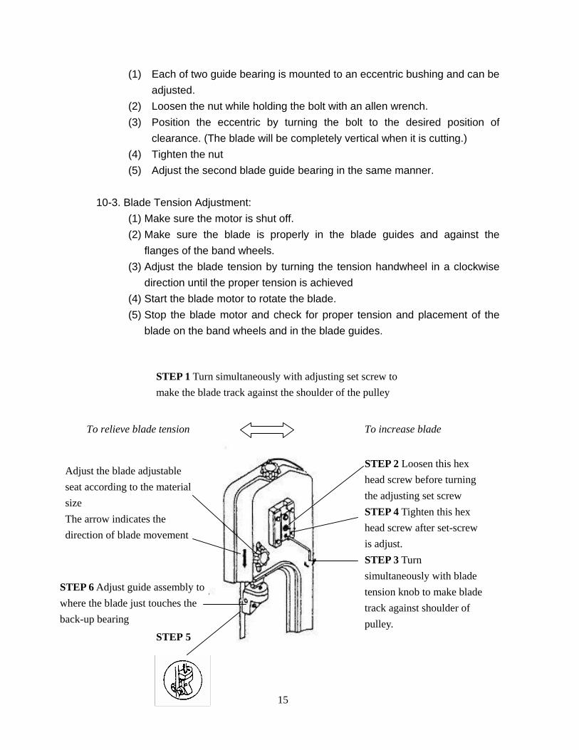
10-3. Blade Tension Adjustment:
(1) Make sure the motor is shut off. (2) Make sure the blade is properly in the blade guides and against the
flanges of the band wheels. (3) Adjust the blade tension by turning the tension handwheel in a clockwise
direction until the proper tension is achieved (4) Start the blade motor to rotate the blade. (5) Stop the blade motor and check for proper tension and placement of the
blade on the band wheels and in the blade guides.
STEP 2 Loosen this hex head screw before turning the adjusting set screw STEP 4 Tighten this hex head screw after set-screw is adjust. STEP 3 Turn simultaneously with blade tension knob to make blade track against shoulder of pulley.
STEP 1 Turn simultaneously with adjusting set screw to make the blade track against the shoulder of the pulley
To increase blade To relieve blade tension
Adjust the blade adjustable seat according to the material size The arrow indicates the direction of blade movement
STEP 6 Adjust guide assembly to where the blade just touches the back-up bearing
STEP 5
16
A
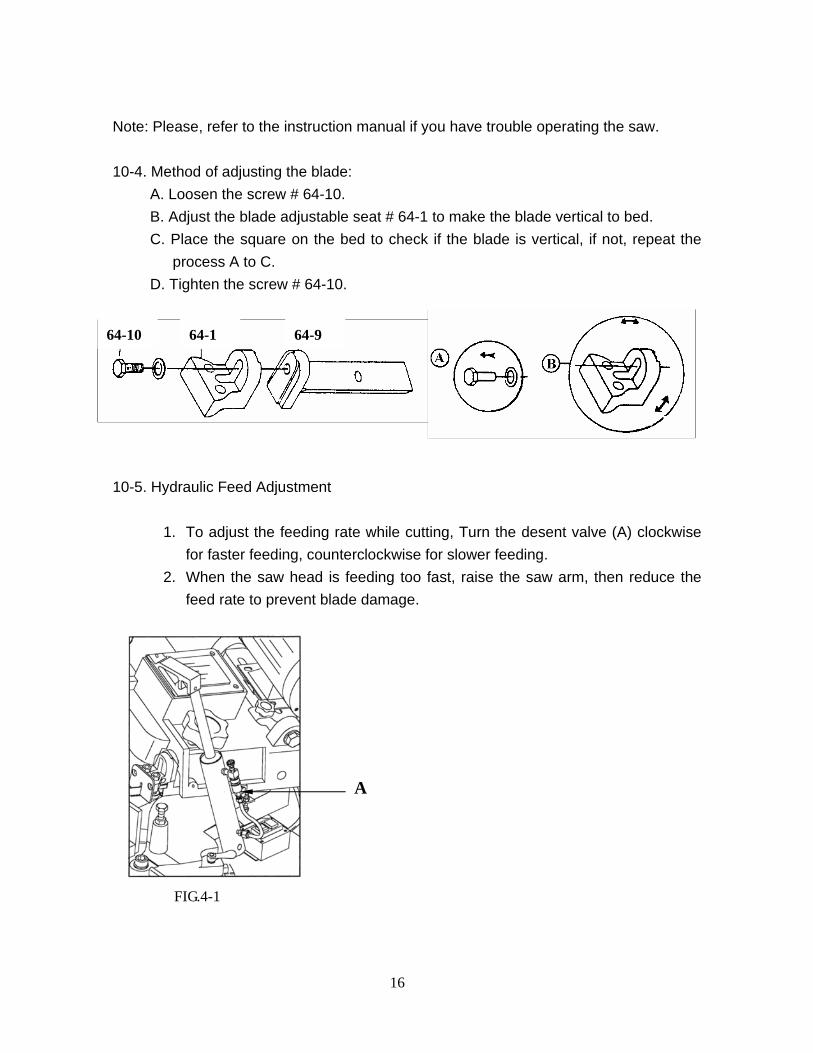
Note: Please, refer to the instruction manual if you have trouble operating the saw. 10-4. Method of adjusting the blade:
A. Loosen the screw # 64-10. B. Adjust the blade adjustable seat # 64-1 to make the blade vertical to bed. C. Place the square on the bed to check if the blade is vertical, if not, repeat the
process A to C. D. Tighten the screw # 64-10.
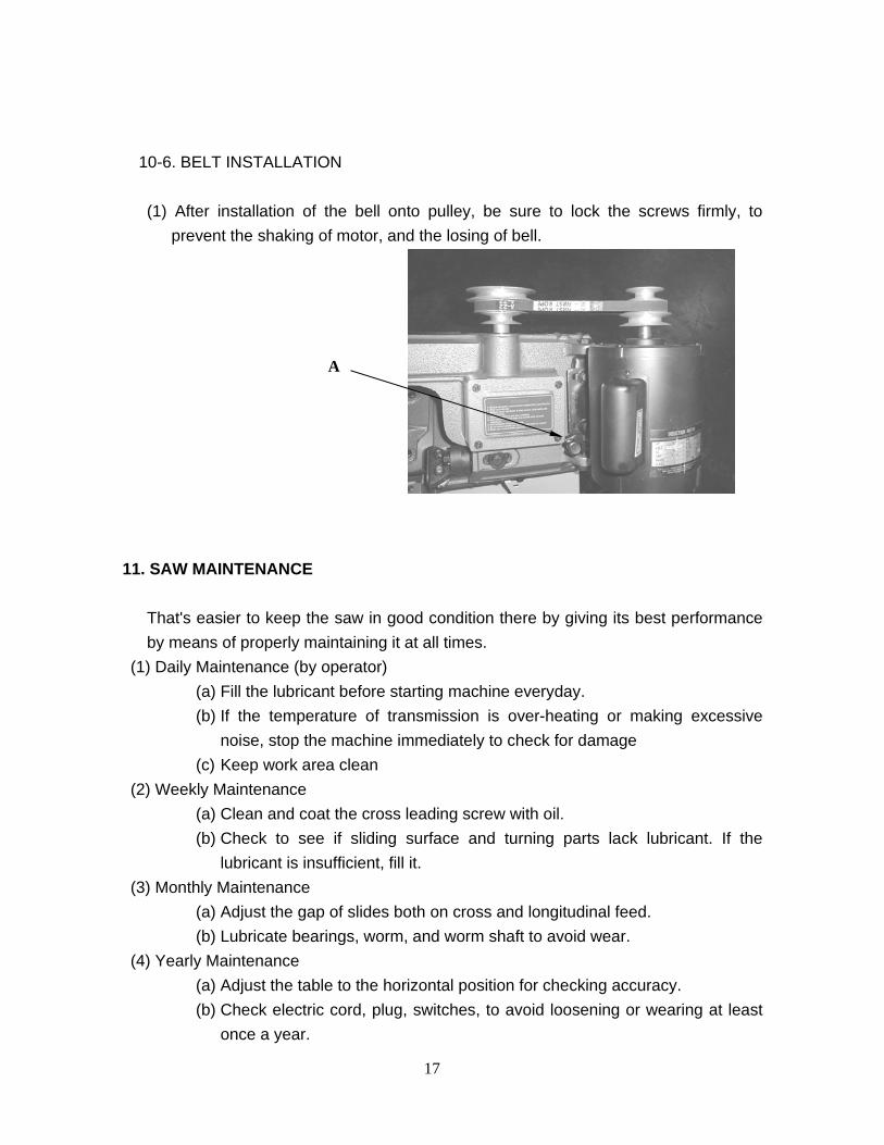
10-5. Hydraulic Feed Adjustment
1. To adjust the feeding rate while cutting, Turn the desent valve (A) clockwise for faster feeding, counterclockwise for slower feeding.
2. When the saw head is feeding too fast, raise the saw arm, then reduce the feed rate to prevent blade damage.
FIG.4-1
64-10 64-1 64-9
17
A
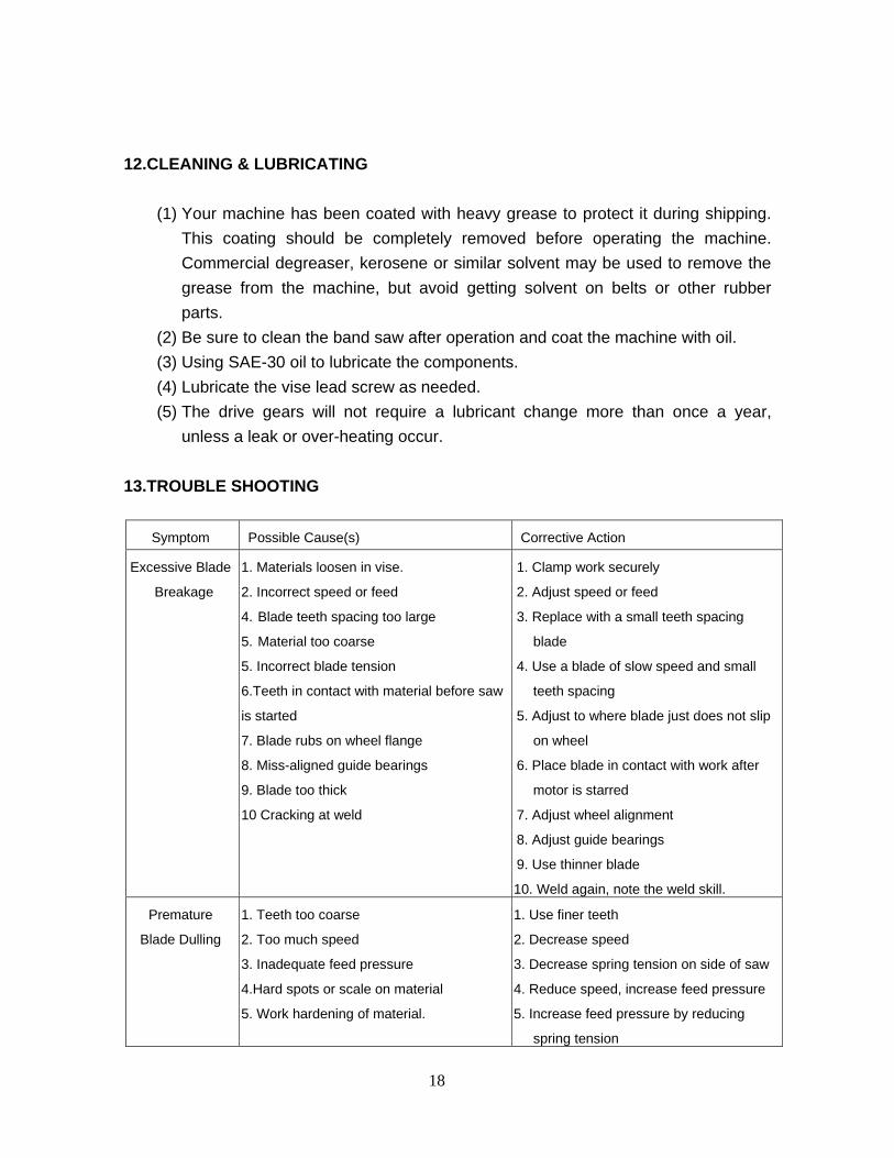
10-6. BELT INSTALLATION
(1) After installation of the bell onto pulley, be sure to lock the screws firmly, to prevent the shaking of motor, and the losing of bell.
11. SAW MAINTENANCE
That's easier to keep the saw in good condition there by giving its best performance by means of properly maintaining it at all times.
(1) Daily Maintenance (by operator) (a) Fill the lubricant before starting machine everyday. (b) If the temperature of transmission is over-heating or making excessive
noise, stop the machine immediately to check for damage (c) Keep work area clean
(2) Weekly Maintenance (a) Clean and coat the cross leading screw with oil. (b) Check to see if sliding surface and turning parts lack lubricant. If the
lubricant is insufficient, fill it. (3) Monthly Maintenance
(a) Adjust the gap of slides both on cross and longitudinal feed. (b) Lubricate bearings, worm, and worm shaft to avoid wear.
(4) Yearly Maintenance (a) Adjust the table to the horizontal position for checking accuracy. (b) Check electric cord, plug, switches, to avoid loosening or wearing at least
once a year.
18
12.CLEANING & LUBRICATING
(1) Your machine has been coated with heavy grease to protect it during shipping. This coating should be completely removed before operating the machine. Commercial degreaser, kerosene or similar solvent may be used to remove the grease from the machine, but avoid getting solvent on belts or other rubber parts.
(2) Be sure to clean the band saw after operation and coat the machine with oil. (3) Using SAE-30 oil to lubricate the components. (4) Lubricate the vise lead screw as needed. (5) The drive gears will not require a lubricant change more than once a year,
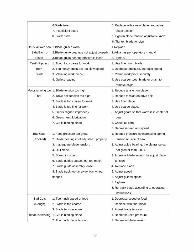
unless a leak or over-heating occur. 13.TROUBLE SHOOTING
Symptom Possible Cause(s) Corrective Action
Excessive Blade
Breakage
1. Materials loosen in vise.
2. Incorrect speed or feed
4. Blade teeth spacing too large
5. Material too coarse
5. Incorrect blade tension
6.Teeth in contact with material before saw
is started
7. Blade rubs on wheel flange
8. Miss-aligned guide bearings
9. Blade too thick
10 Cracking at weld
1. Clamp work securely
2. Adjust speed or feed
3. Replace with a small teeth spacing
blade
4. Use a blade of slow speed and small
teeth spacing
5. Adjust to where blade just does not slip
on wheel
6. Place blade in contact with work after
motor is starred
7. Adjust wheel alignment
8. Adjust guide bearings
9. Use thinner blade
10. Weld again, note the weld skill.
Premature
Blade Dulling
1. Teeth too coarse
2. Too much speed
3. Inadequate feed pressure
4.Hard spots or scale on material
5. Work hardening of material.
1. Use finer teeth
2. Decrease speed
3. Decrease spring tension on side of saw
4. Reduce speed, increase feed pressure
5. Increase feed pressure by reducing
spring tension
19
6.Blade twist
7. Insufficient blade
8. Blade slide
6. Replace with a new blade, and adjust
blade tension
7. Tighten blade tension adjustable knob
8. Tighten blade tension
Unusual Wear on
Side/Back of
Blade
1. Blade guides worn.
2. Blade guide bearings not adjust properly
3. Blade guide bearing bracket is loose
1. Replace.
2. Adjust as per operators manual
3. Tighten.
Teeth Ripping
from
Blade.
1. Tooth too coarse for work
2. Too heavy pressure; too slow speed.
3. Vibrating work-piece.
4. Gullets loading
1. Use finer tooth blade.
2. Decrease pressure, increase speed
3. Clamp work piece securely
4. Use coarser tooth blade or brush to
remove chips.
Motor running too
hot
1. Blade tension too high.
2. Drive belt tension too high.
3. Blade is too coarse for work
4. Blade is too fine for work
5. Gears aligned improperly
6. Gears need lubrication
7. Cut is binding blade
1. Reduce tension on blade.
2. Reduce tension on drive belt.
3. Use finer blade.
4. Use coarse blade.
5. Adjust gears so that worm is in center of
gear.
6. Check oil path.
7. Decrease reed anti speed
Bad Cuts
(Crooked)
1. Feed pressure too great.
2. Guide bearings not adjusted properly
3. Inadequate blade tension.
4. Dull blade.
5. Speed incorrect.
6. Blade guides spaced out too much
7. Blade guide assembly loose
8. Blade truck too far away from wheel
flanges
1. Reduce pressure by increasing spring
tension on side of saw
2. Adjust guide bearing, the clearance can
not greater than 0.001.
3. Increase blade tension by adjust blade
tension
4. Replace blade
5. Adjust speed
6. Adjust guides space.
7. Tighten
8. Re-track blade according to operating
instructions.
Bad Cuts
(Rough)
1. Too much speed or feed
2. Blade is too coarse
3. Blade tension loose
1. Decrease speed or feed.
2. Replace with finer blade.
3. Adjust blade tension.
Blade is twisting
1. Cut is binding blade.
2. Too much blade tension.
1. Decrease reed pressure.
2. Decrease blade tension.
20
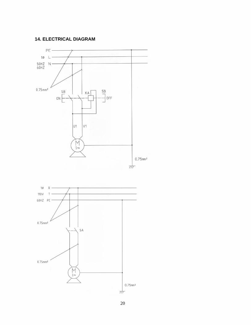
14. ELECTRICAL DIAGRAM