Embed Size (px)
Citation preview
Department of Architecture and Civil Engineering Division of Construction Management Research Group Name: Construction Management CHALMERS UNIVERSITY OF TECHNOLOGY Master’s Thesis BOMX02-2017-70 Gothenburg, Sweden 2017
BIM-uses Concerning 3D-reinforcements in the construction process
Master’s Thesis in the Master’s Program Design and Construction Project Management
YUSUF OMAR
To edit footer choose “Footer” from the
Insert tool bar and then choose “Edit
footer”. After editing choose “Close
header and footer”.

MASTER’S THESIS BOMX02-2017-70
BIM-uses Concerning 3D-reinforcements in the construction process
Master’s Thesis in the Master’s Program Design and Construction Project Management
YUSUF OMAR
Department of Architecture and Civil Engineering
Division of Construction Management
Research Group Name: Construction Management: Construction Management
CHALMERS UNIVERSITY OF TECHNOLOGY
Göteborg, Sweden 2017

IV
BIM-uses
Concerning 3D-reinforcements in the construction process
Master’s Thesis in the Master’s Program Design and Construction Project
Management
YUSUF OMAR
© YUSUF OMAR, 2017
Master Thesis BOMX02-2017-70/ Institutional for Department of Architecture and
Civil Engineering,
Chalmers Technical University 2017
Department of Architecture and Civil Engineering
Division of Construction Management
Research Group Name: Construction Management: Construction Management
Chalmers University of Technology
SE-412 96 Göteborg
Sweden
Telephone: + 46 (0)31-772 1000

CHALMERS Architecture and Civil Engineering, Master’s Thesis BOMX02-2017-70 V
Cover:
Here's how the construction site looks through the HoloLens glasses. The glasses
provides the construction worker an opportunity to see the environment and the digital
model at the same time.
Nohrstedt, Linda. ”Masken styr armeringen på ESS-bygget”. Nyteknik, Photo taken
by Anders Hansson, BYGG, Date :4 April.2016,
http://www.nyteknik.se/bygg/masken-styr-armeringen-pa-ess-bygget-6840540.
Göteborg, Sweden, 2017

VI
BIM-uses
Concerning 3D-reinforcements in the construction process
Master’s thesis in the Master’s Programme
YUSUF OMAR
Department of Architecture and Civil Engineering
Division of Construction Management
Research Group Name: Construction Management
Chalmers University of Technology
ABSTRACT
In recent decades, many industries have experienced how digitization has changed
both ways of working and its results. The construction industry is now facing such
development. The master thesis demonstrates how the current reinforcement process
looks and how the future reinforcement process estimates to look. In addition, what
upcoming projects should consider if they desire to implement/utilize digitalized
reinforcement. The purpose of this master thesis were to find out the required
management and technology for implementing digitalized reinforcement. At the same
time figure out how the reinforcement process looks from the drawing desk to the
construction site. The methodology performed in this master thesis has been
interviews with the concerned project participants in the reinforcement processes and
a 3D-modeling test in the project; Kvibergs-Ängar. The findings of this master thesis
has been that there is a need of communication improvements between the structural
engineers and the contractors. To reach an intact information flow must the contractor
become clearer with their description of the casting stages they want and the
reinforcement method they desire to the structural engineers, at the same time do the
contractors need to procure the reinforcement supplier earlier in the process. In order
to get the information right from the start do all the participants in the reinforcement
process need to attend earlier in the process. Currently are there some good
opportunities with visualizing and working with digitized reinforcement from the
designer’s drawing board to the construction worker's workplace on site. The current
IT-tools allows the structural engineer create reinforcement specifications/schedules
through two different alternatives. The first alternatives is creating it in the Revit
structure and Teklas structure plugin app Q-reinforcement which has now developed
to QR-cloud service. Alternatively, the second method is Solibri model checker where
the contractor and supplier are allowed to view the color-coded reinforcement and
follow up its order and delivery status. For visualization, purpose on the construction
site do the contractor have two good option to utilize such as Glue BIM 360 or Tekla
BIMsight/ Field on their IPads. Furthermore has few studies earlier addressed the use
of digitalized reinforcement process among the site workers. Thus, the findings
provide practitioners and researchers insight into how current practices maybe
improved, as well as areas where more research is needed.
Key words: BIM, BIM-Uses, Digital Reinforcement, The Reinforcement Process.

CHALMERS Architecture and Civil Engineering, Master’s Thesis BOMX02-2017-70 VII
Contents
ABSTRACT VI
CONTENTS VII
PREFACE X
NOTATIONS XI
1 INTRODUCTION 1
1.1 Background 1
1.2 Problem statement 2
1.3 Purpose 2
1.4 Limitations 2
1.5 Research Questionings 2
1.6 Disposition 3
2 THEORETICAL BACKGROUND 4
2.1 General information about BIM 4 2.1.1 Building Information Modelling lifecycle 4
2.2 BIM-Use 7
2.2.1 Determine the purpose for implementing BIM 8
2.3 Cooperating participant in a construction project 11
2.3.1 Design programs 12 2.3.2 Coordination programs 12
2.3.3 Construction Site Visualization Applications 13
2.4 Interoperability 14 2.4.1 Utilizing IFC 14
2.5 The Reinforcement process 15 2.5.1 Actors within the reinforcement process 16
3 METHOD DESCRIPTION 26
3.1 Research methods 26
3.2 Literature study 26
3.3 Skanska’s internal network 27
3.4 Interview design 28
3.5 Collection of empirical data 29 3.5.1 Transcription 29
3.5.2 Selection of relevant data 29 3.5.3 3D-Modelling-Tools 29 3.5.4 Description of the case study project 30
3.6 Skanska: Company presentation 31
VIII
3.6.1 Organizational view of Skanska 31
3.6.2 Building Information Management (BIM) within Skanska 31
4 RESULTS 32
4.1 Interview results 32
4.1.1 Skanska Sweden Structural engineers current work set 32 4.1.2 Skanska Norway Structural engineers current work set 35 4.1.3 Skanska Sweden Procurement /Contractors 36 4.1.4 Internal & External Reinforcement Suppliers 39 4.1.5 Skanska Sweden Construction Workers 45
4.2 3D-Modelling results 48 4.2.1 Revit. 49 4.2.2 Q-reinfrocement. 50
4.2.3 Solibri. 52 4.2.4 Iconstruct Navis Works. 54 4.2.5 BIM 360 Glue. 56
5 DISCUSSION & CONCLUSIONS 57
5.1 Communication and interoperability 57 5.1.1 Structural engineer 57
5.1.2 Contractors 58 5.1.3 Suppliers 58
5.1.4 Construction workers 58 5.1.5 New roles 59 5.1.6 Preferred Contract form. 59
5.1.7 The current & future reinforcement process 60
5.1.8 Realization through BIM-use reinforcement 62
5.2 Conclusion 63
6 SUGGESTIONS FOR FURTHER RESEARCH 64
7 REFERENCES 65
8 APPENDICES 68
8.1 The Swedish design requirement 69
8.2 Contractual form of the project: Kungälvs Sjukhus 72
8.3 Project: Valand in Kungsbacka, Tekla BIM Sight 74 8.3.1 Project: Valand in Kungsbacka, Tekla BIM Sight 75
8.4 Traditional Reinforcement Schedule 76
8.5 Specification sheet 2A 77

CHALMERS Architecture and Civil Engineering, Master’s Thesis BOMX02-2017-70 IX

X
Preface
First of all, I would like to express a sincere gratitude and appreciation to Helena
Burstrand Knutsson, Group Manager of the Technological Department in Skanska for the
assignment and Ulf Thorell, BIM coordinator. Ulf, with his enormous expertise and
knowledge, not least in the field of this subject, has contributed with many interesting
views, encouragement and guidance.
I would also like to thank Henning Habberstad, Jonas Lot, Patric Bryntesson, Ronnie
Lindh, Thomas Eriksson and Daniel Isaksson who have been kind enough to take their
time during this master's thesis. Both Henning, Jonas, Patric and Ronnie works with BIM
questions in Skanska technical departments while Thomas and Daniel works for the
reinforcement suppliers Celsa Steel. All participants works/develops 3D reinforcement
and has contributed too many thoughtful aspects and beyond.
Most of all, we would like to thank our respondents for this master thesis. For being
helpful to enable this paper's interview questions and share a little of their valuable time
and insight into their experiences in the reinforcement process.
Finally, I would like to thank my supervisor Mattias Roupé for his guidance and advice,
comments and understanding during this course of Master's thesis. Furthermore would I
also want to thank the opponent for the critical and relevant reviews.

CHALMERS Architecture and Civil Engineering, Master’s Thesis BOMX02-2017-70 XI
Notations
2D Drawing: An abbreviation for two-dimensional paper drawing, the space
perspective is the length and width.
3D Design: An abbreviation for three-dimensional, is the space perspective where
length, breadth and depth are perceived.
BIM: Building Information Model/Management
DWG: Drawings (CAD programs filename extension)
IFC: Industry Foundation Classes
IFD: INTERNATIONAL FRAMEWORKS for Dictionaries
ISO: International Organization for Standardization
RTV: (project) files for actual Revit® projects
XII
Table of Figures
Figure 1 BIM lifecycle sharing information (Mistry,H. 2016) ...................................... 4 Figure 2 Illustration of the various Maturity levels in usage of BIM (Government
Construction Client Group From the BIM Industry Working Group, 2011) ................. 5 Figure 3 The Components of a BIM Use (Kraider, Messner & Dubler, 2010) ............. 7 Figure 4 The BIM Use Purposes (Kraider, Messner & Dubler, 2010) .......................... 8
Figure 5 The BIM Use Purpose and Objectives (Kraider, Messner & Dubler, 2010) ... 9 Figure 6 BIM Use Elaboration Characteristics (Kraider, Messner & Dubler, 2010) .. 10 Figure 7 Structural engineers reinforcement processes (Engström et al., 2011). ........ 16 Figure 8 Reinforcement specifications/schedule (Engström et al., 2011). .................. 17 Figure 9 color-coded 3D - reinforcement drawings Celsa Steelservice, (2012) .......... 18
Figure 10 Reinforcement is delivered colure coded Celsa Steelservice, (2012). ........ 19 Figure 11Design Bid Build Contract Form based on (Mittbygge, 2011) .................... 20 Figure 12 Design Build Contract Form based on (Mittbygge, 2011) .......................... 21
Figure 13 Juridical order if contradictory information arises in the contract
documentation in Swedish standard agreements (BIM Alliance (2016) ..................... 22 Figure 14 Skanska Process Map Design of House projcets (One Skanska, 2017b) .... 27 Figure 15 Facility & Neighborhood design of Kvibergs-Ängar (One Skanska, 2017b)
...................................................................................................................................... 30 Figure 16 Kvibergs Ängar Revit 2017 Modell ............................................................ 48
Figure 17 3D reinforcement elevator pit Kvibergs Ängar Revit 2017 Modell ............ 49 Figure 18 Elevator pit 3D reinforcement Kvibergs Ängar Revit 2017 Modell ........... 49
Figure 19 3D-reinforcement Schedule Kvibergs-Ängar Q-armering .......................... 50 Figure 20 3D-reinforcement Schedule Kvibergs-Ängar Q-armering .......................... 51 Figure 21 3D reinforcement schedule Kvibergs Ängar Solibri .................................. 52
Figure 22 3D reinforcement Collison Kvibergs Ängar Solibri .................................. 52 Figure 23 3D reinforcement Shape code C Kvibergs Ängar Solibri .......................... 53
Figure 24 3D reinforcement color-coding Kvibergs Ängar (Iconstruct) NavisWorks54 Figure 25 3D reinforcement color coding Shape code : B Kvibergs Ängar (Iconstruct)
NavisWorks .................................................................................................................. 55 Figure 26 3D reinforcement color coding Shape code : A Kvibergs Ängar
(Iconstruct) NavisWorks .............................................................................................. 55 Figure 27 3D-reinforcement visualized in Glue BIM 360 ........................................... 56 Figure 28 Edit reinforcement Glue BIM 360 ............................................................... 56 Figure 29 Current reinforcement process (Engström et al ,2011). .............................. 60
Figure 30 Future reinforcement process (Engström et al ,2011). ................................ 61

CHALMERS Architecture and Civil Engineering, Master’s Thesis BOMX02-2017-70 XIII


CHALMERS Architecture and Civil Engineering, Master’s Thesis BOMX02-2017-70 1
1 Introduction
The architectural-engineering-construction (AEC) industry creates complex and unique
products, based on highly specialized processes. These processes utilizes Building
Information Modeling Tools (BIM-tools), which has improved construction projects in
recent years. The 3D and 4D modelling ( 4D; 3D plus schedule time) tools offers the
construction projects a significant possibility to facilitate its development process and
gives the project participant a good chance to follow how the project progresses
(Fischer and Haymaker 2001, Staub-French and Fisher 2001, Kam et al., 2003).
Kensek & Noble (2014) continues with mentioning that BIM has developed from only
being used by innovative software companies and universities to being widely used by
the architecture, engineering and construction profession. Eastman, et al. (2008)
explains that BIM dates back to the 1970s but has become more noticeable in recent
years, and that the concept is not new. Byggindustrin (2011) also mentions that the
interest for Building Information Modelling (BIM) is increasing mostly, due to low
efficiency and productivity in the Swedish construction industry. Lutz & Gabrielsson,
(2002) argues that construction projects have at least 80% similar processes within all
projects, which creates room for huge opportunities to make improvements within.
These improvements can be achieved through BIM, which provides the professions a
possibility to model advanced 3D reinforcement models, which creates complete,
detailed and accurate reinforcement designs which offers scheduling tools for the
reinforcement which is mounted and rolled out on the construction site. This BIM-use
application within project management offers the opportunity to improve management
of the project and the delivery of construction projects of any size and complexity
(Vasshaug, 2014).
1.1 Background
Skanska located in Sweden is one of the world’s leading construction companies. It is
a huge provider of large house and infrastructure construction services and
development of public-private partnership. That construct everything from small
renovation projects to billion-dollar projects (Skanska a, 2015). The company
operates in Gothenburg, where their technical house building department desire to
develop their 3D BIM-work set through adding 3D-reinforcement to their Building
information management list. The company has previous experience of working with
3D-modelled reinforcement and desires to develop their technical housing department
through utilizing their own technology, which they have in their other technical
departments in Sweden. Skanska housing production department purchases in the
current situation their reinforcement specifications from hired consultants, which can
be costly. Skanska believes that 3D-BIM reinforcement specifications can make the
construction process cheaper through getting them better flow from their structural
engineers. At the same time, can they be more effective in the purchasing process and
give better quality of their work-set with the reinforcement on site with their
construction workers.
2
1.2 Problem statement
The problem statement of the master thesis is to develop todays work set with
reinforcement drawings. Mostly because most of the reinforcement
drawings/specifications done today are in 2D-pdf drawings, which later are utilized to
design the reinforcement specifications/schedule. Skanska wants to utilize their own
main software for construction drawings in Autodesk program Revit instead of
Skanska’s current SSI supplier, which designs construction drawings in the software
program Tekla.
1.3 Purpose
Skanska’s technical housebuilding department in Gothenburg has a great desire to be
capable of designing their own reinforcement specifications so they do not have to
hire in consultants. The main purpose of this master thesis is to evaluate the optimal
management of the entire chain, from drawing mode to purchasing- (call-off the
purchase of armor) to production.
1.4 Limitations
The study will only conduct BIM-uses concerning 3D-reinforcements. The study will
utilize the technical capacity of the technical department and the purchasing
department. Suggestions from the production site will be evaluated and how the
technical and the production site collaboration can be done more effectively. Only
BIM-uses concerning reinforcement will be investigated.
1.5 Research Questionings
How could 3D-BIM reinforcement be implemented and utilized in Skanska’s
technical housebuilding department?
How could 3D-BIM reinforcement process function and be applied, from
drawing desk and be quantified on the purchasing desk to the production
management processes?
CHALMERS Architecture and Civil Engineering, Master’s Thesis BOMX02-2017-70 3
1.6 Disposition
The master thesis first chapter begins with a general instruction of BIM, the thesis
purpose, limits and ends with research questions.
In the methodology chapter is it described how the master thesis is conducted and
how the interview design was formed. In addition, also how the empirical data was
collected. Further on the chapter includes a small description of the case study project
performed in this thesis and introductions of the company Skanska way of working
process with BIM.
The methodology chapter is followed by the theoretical background, which the master
thesis is based on. This chapter gives the readers a general and more focused
information about BIM, BIM-Uses, contractual laws, design regulations, software
programs and the reinforcement process.
The result chapter presents the collected results of the performed interviews and the
performed design test on the case study project; Kvibergs-Ängar. This part concludes
with a summarizing analysis of the current state proposed to form the basis for further
information process development.
The discussion chapter discusses the analysed results, which is evaluated based on the
reports purpose, objectives and issues. Finally, some concluding remarks, main key
points and a few recommendations for future studies is presented.
4
2 Theoretical background
The theoretical background chapter explains the different theories within the subject
BIM, BIM-uses and the reinforcement process.
2.1 General information about BIM
In summary Building Information Management (BIM) is considered to be and
described as a computer-tailored approach, which is utilized by members in the
project team to effectively manage the information throughout the project lifecycle.
Building information models contains parametric data which describes its attributes
and object orientation of what they represent. The model continuously updates itself,
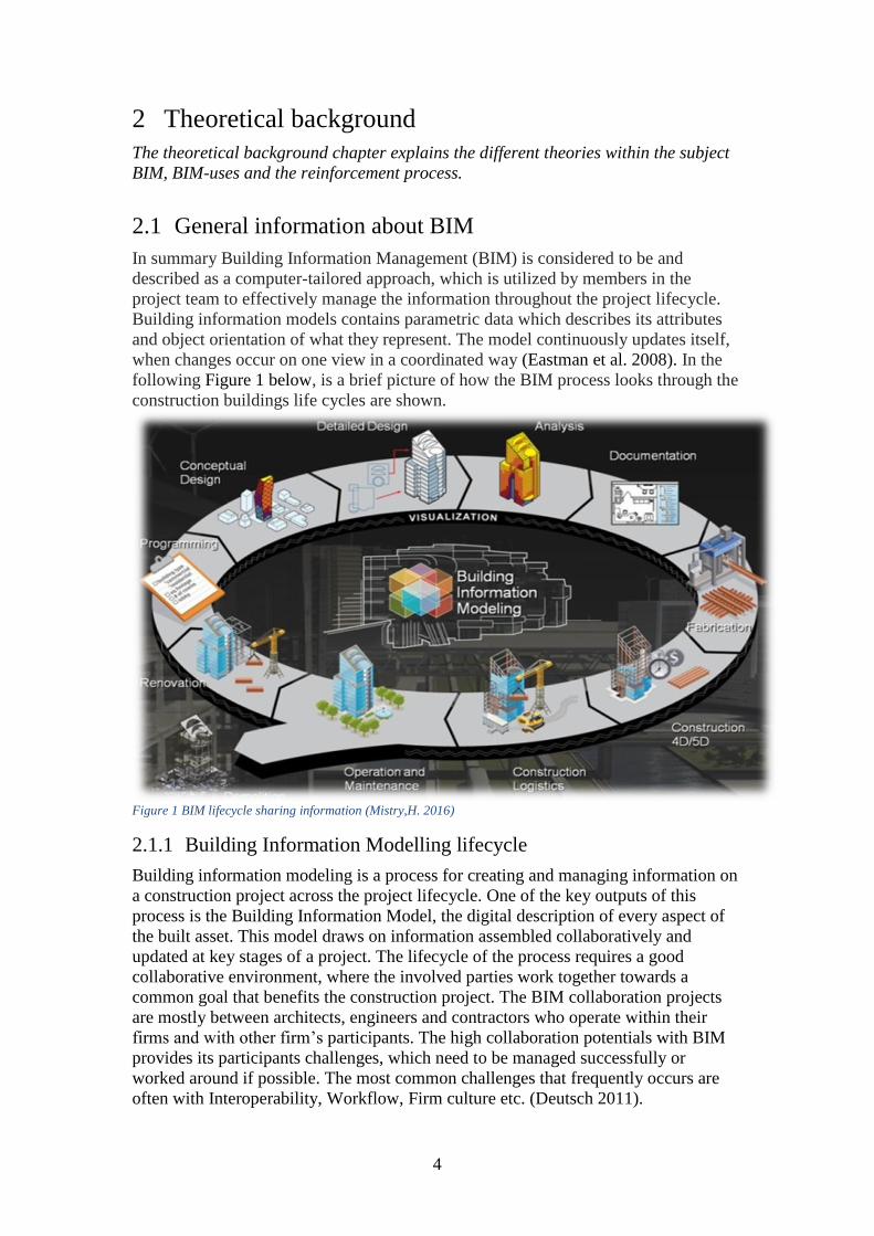
when changes occur on one view in a coordinated way (Eastman et al. 2008). In the
following Figure 1 below, is a brief picture of how the BIM process looks through the
construction buildings life cycles are shown.
Figure 1 BIM lifecycle sharing information (Mistry,H. 2016)
2.1.1 Building Information Modelling lifecycle
Building information modeling is a process for creating and managing information on
a construction project across the project lifecycle. One of the key outputs of this
process is the Building Information Model, the digital description of every aspect of
the built asset. This model draws on information assembled collaboratively and
updated at key stages of a project. The lifecycle of the process requires a good
collaborative environment, where the involved parties work together towards a
common goal that benefits the construction project. The BIM collaboration projects
are mostly between architects, engineers and contractors who operate within their
firms and with other firm’s participants. The high collaboration potentials with BIM
provides its participants challenges, which need to be managed successfully or
worked around if possible. The most common challenges that frequently occurs are
often with Interoperability, Workflow, Firm culture etc. (Deutsch 2011).
CHALMERS Architecture and Civil Engineering, Master’s Thesis BOMX02-2017-70 5
American National Institute of Building Sciences (2007) further down describes a
profound description about building information management:
" BIM is a digital representation of physical and functional characteristics of a
facility. As such, it serves as a shared knowledge resource for information about a
facility forming a reliable basis for decisions during its lifecycle from inception
onward. A basic premise of BIM is collaboration by different stakeholders at different
phases of the lifecycle of a facility to insert, extract, update, or modify information in
the BIM to support and reflect the roles of the stakeholder. BIM is a shared digital
representation founded on open standards for interoperability"
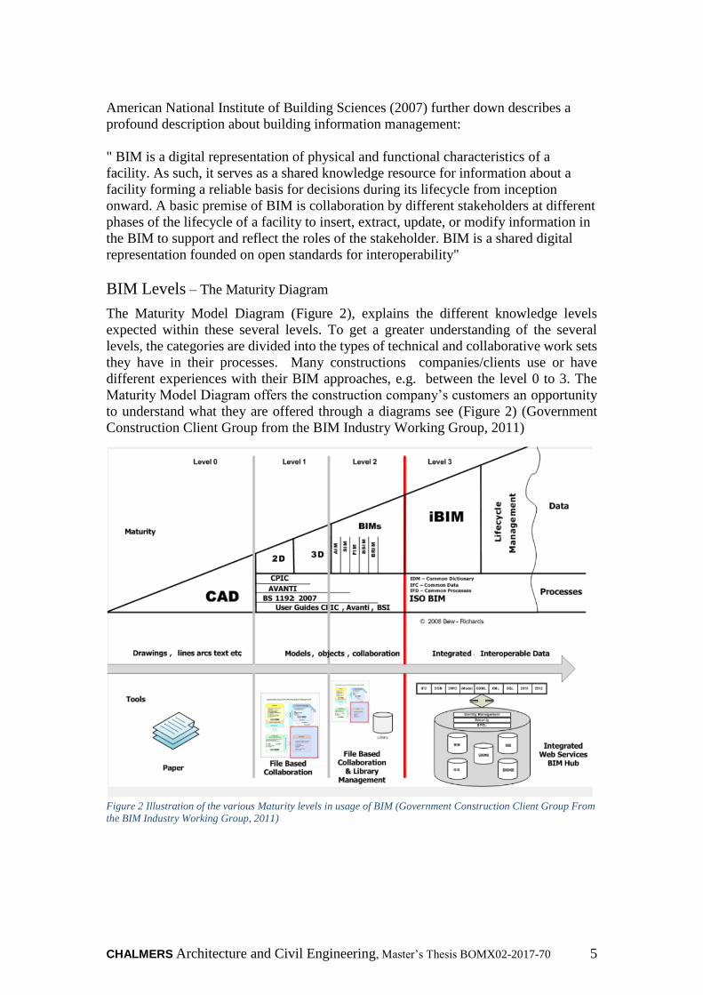
BIM Levels – The Maturity Diagram
The Maturity Model Diagram (Figure 2), explains the different knowledge levels
expected within these several levels. To get a greater understanding of the several
levels, the categories are divided into the types of technical and collaborative work sets
they have in their processes. Many constructions companies/clients use or have
different experiences with their BIM approaches, e.g. between the level 0 to 3. The
Maturity Model Diagram offers the construction company’s customers an opportunity
to understand what they are offered through a diagrams see (Figure 2) (Government
Construction Client Group from the BIM Industry Working Group, 2011)
Figure 2 Illustration of the various Maturity levels in usage of BIM (Government Construction Client Group From
the BIM Industry Working Group, 2011)

6
Description about the various levels.
The first level 0 in the Maturity Model Diagram is CAD, which usually are 2D
electronic paper or ordinary paper form. The following level 1 contains 2D or 3D
formats through utilizing a collaboration tool that provides a common data environment
with standard data structures and formats. Level 2 offers the construction companies
the opportunity to use other new approaches with 4D (3D, plus time) and 5D cost
elements as well as feed operational systems. The third and last level the companies
utilize open BIM-processes to the fullest. In addition, the File standards as IFC/IFD
files are managed transparently by collaborative model servers, which later would be
regarded as iBIM or integrated BIM that compiles all the technical processes
(Government Construction Client Group From the BIM Industry Working Group,
2011).
Development of BIM BIM Alliance (2016) states that contractual and commercial issues is something that
has been overlooked by technical development. At the same time, the development of
BIM develops at much higher speed then before estimated, but demands better
contract conditions, organizational developments, software etc.

CHALMERS Architecture and Civil Engineering, Master’s Thesis BOMX02-2017-70 7
2.2 BIM-Use
Kraider, Messner & Dubler, (2010) defines building information modeling as “the act
of creating an electronic modeling of a facility for the purpose of visualization,
engineering analysis, conflict analysis, code criteria checking, cost engineering, as-
built product, budgeting and many other purposes.”
A consistent digital language needs to be developed so better communication fosters
within the digital world. BIM-uses are further described as “a method of applying
Building Information Modeling during a facility’s lifecycle to achieve one or more specific
objectives.” Further, on it is mentioned that a BIM use can only be classified with the
intention of implementing BIM thought the life of the facility. Some other
characteristics can be defined to properly identify and communicate a BIM Use. More
information is described in figure 3 which explains the varying levels which depend
upon the level of specificity required for different applications of the uses (Kraider,
Messner & Dubler, 2010).
Figure 3 The Components of a BIM Use (Kraider, Messner & Dubler, 2010)
The uses of BIM documents was last released in 2013, with the purpose of
communicating the BIM Use classification system and it’s purposes. The document
presented that BIM classifications provides users a common language for the Uses of
Building Information Modeling. A common language, which improves the purposes
and methods for implementing BIM throughout the lifecycle of a facility (Kraider,
Messner & Dubler, 2010).
8
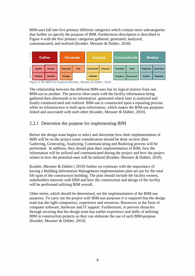
BIM-uses fall into five primary different categories which contain more subcategories
that further on specify the purpose of BIM. Furthermore description is described in
Figure 4 with the five primary categories gathered, generated, analyzed,
communicated, and realized (Kraider, Messner & Dubler, 2010).
Figure 4 The BIM Use Purposes (Kraider, Messner & Dubler, 2010)
The relationship between the different BIM-uses has its logical motion from one
BIM-use to another. The process often starts with the facility information being
gathered then afterwards is its information generated which later is analyzed and
finally communicated and realized. BIM-use is constructed upon a repeating process
while its infrastructure is built upon information, which makes the BIM-use purposes
linked and associated with each other (Kraider, Messner & Dubler, 2010).
2.2.1 Determine the purpose for implementing BIM
Before the design team begins to select and determine how their implementation of
BIM will be on the project some consideration should be done on how their
Gathering, Generating, Analyzing, Communicating and Realizing process will be
performed. In addition, they should plan their implementation of BIM, how the
information will be utilized and communicated during the project and how the project
relates to how the potential-uses will be utilized (Kraider, Messner & Dubler, 2010).
Kraider, Messner & Dubler ( 2010) further on continues with the importance of
having a Building Information Management implementation plan set out for the total
life span of the construction building. The plan should include the facility owners,
stakeholders interests with BIM and how the construction and design of the facility
will be performed utilizing BIM overall.
Other terms, which should be determined, are the implementation of the BIM-use
purposes. To carry out the project with BIM-use purposes it is required that the design
team has the right competence, experience and resources. Resources in the form of
computer software, hardware and IT support. Furthermore, to prevent obstacles
through securing that the design team has earlier experience and skills of utilizing
BIM in construction projects so they can elaborate the use of each BIM-purpose
(Kraider, Messner & Dubler, 2010).

CHALMERS Architecture and Civil Engineering, Master’s Thesis BOMX02-2017-70 9
A short resume of the updated BIM Use Purposes with their objectives and synonyms
is shown within the BIM Use Ontology in figure 5. The category, which this master
thesis will immerse in, is the fifth BIM use purpose, Realize. Furthermore the fifth
purpose contains four other sub categories that further specifies the aim of the BIM
Use Purpose (Kraider, Messner & Dubler, 2010).
Figure 5 The BIM Use Purpose and Objectives (Kraider, Messner & Dubler, 2010)

10
Realize
The objective of the BIM use; Realize’s purpose is to construct or control the physical
elements of the facility through utilizing the information and the (BIM data) the
facility contains. Furthermore, it removes the direct input of needed human interaction
in the construction industry through utilizing other construction methods such as
fabricating, assembling, controlling and regulating elements of the facility. This in
turn may lead to a more improved productivity of the construction and operation of
the facilities (Kraider, Messner & Dubler, 2010)
The BIM-use purpose Realize has four other sub-purposes whose aim is to utilize
facilities information in numerus other ways e.g. manufacturing its elements through
fabrication, prefabricating and bringing together the separate elements while at the
same time manipulating the executing equipment and directly using the information,
the facility contains (Kraider, Messner & Dubler, 2010)
BIM-use elaboration characteristics
When the decision of which implementation form the design team decides to carry
out, they need to determine which discipline, which phase, which facility elements,
and to what level of development these BIM Use purposes will be implemented.
Further description can be seen down on the BIM Use elaboration characteristics
Figure 6 (Kraider, Messner & Dubler, 2010).
Figure 6 BIM Use Elaboration Characteristics (Kraider, Messner & Dubler, 2010)
.

CHALMERS Architecture and Civil Engineering, Master’s Thesis BOMX02-2017-70 11
2.3 Cooperating participant in a construction project
Building information management is about sharing information between various
project participants who contribute to constructing the construction building. The
participants have different roles in the project and utilize BIM to facilitate the project
process. Building information models often provides the client the possibility to
follow and monitor the projects development. The design allows the client in an early
stage to virtually navigate in the model and see how the finished structure will be.
While the building information model provides the design manager better
communication between clients and the other parties involved in the project with a
good overview of the project and coordination opportunities. The contractor mostly
prefers the simulation of the model with integrated time scheduling, rough estimation
of cost with simulating through the project. At the same time the suppliers have the
opportunity to speed up the manufacturing process through utilizing the CNC files or
manufacturing drawings, furthermore the facility owner has the ability also to use the
BIM model in the facility management stage to manage the reparation , operation and
maintenance of the building(Granroth, 2011).

12
2.3.1 Design programs
Some of the software programs that facilitates the usage of BIM are the following
software programs.
Tekla Structures
Tekla is mostly used to design and model residential/office buildings, factories,
offshore buildings etc. in 3D. The software program Tekla provides the designers the
opportunity to design with enough information required for a building information
model. The software program has the possibility to manage and handle complex
detailed rich structures, with any sort of construction material (Tekla, 2012a).
Revit Structures
Revit is a software that gives the designer, the ability to weave together the different
disciplines drawings in the construction industry. These disciplines are ventilation,
electrical plumbing, construction, and architectural drawings. Revit is a program that
is made up of items instead of lines; the software minimizes project management
errors while improving the shared device, and cooperation (Autodesk 2015).
2.3.2 Coordination programs
Solibri Model Checker
Solibri Model Checker is a coordination program that analyzes models, collisions
with a variety of parameters such as the building's geometries, spaces, and complete
designs. A program which is suitable for implementing quality controls, visualization,
navigation, intuitive walk-through functionality, escape routes etc. at the same time
checking that the building meets its standards and regulations. Solibri model imports
only the IFC files which are a file format that is suitable for numerous applications
and programs. Further information about IFC can be found in the interoperability
chapter (Solibri, 2016).
Autodesk Navisworks Manage 2016
Navisworks is a program that allows all the disciplines to coordinate and carry out
collision checks. It also gives the coordinators the possibility to perform
visualization, which are connected to the timeline and its various construction
elements. These tools provides the BIM-coordinator a possibility to predict in advance
the projects’ different challenges. It offers the BIM-coordinator a variety of features
that are well suited for visualization and presentations.
CHALMERS Architecture and Civil Engineering, Master’s Thesis BOMX02-2017-70 13
2.3.3 Construction Site Visualization Applications
Apricon C3
For coordination purpose the building information and files are stored in similar
Webb-based cloud service portal named; Apricon C3.Through the cloud service the
projects participants have access to the construction models, files and documentations,
which concerns the project. Apricon C3 can also be used as a mobile application on
the tablets in construction sites. The cloud service also provides reports and
communication solutions and documents (Apricon, 2015).
Autodesk BIM 360 Glue
Glue BIM 360 is a cloud based coordination program that provides the project team
the opportunity to collaborate between all project participants in the computer and
tablet. Glue BIM 360 has the possibility to work with these following file formats e.g.
- IFC-, RVT- and DWG. The program has also the possibility to handle collision
controls, combines model coordination with project quantities and schedule to deliver
simulation and quantification features, including analysis of time and cost. Entire
project models can be published and freely viewed using Autodesk Navis Works
Freedom software.
Tekla BIMsight
Tekla BIM-sight is a coordination program that improves communication between
production site and the consultants by offering them the opportunity to provide the
quality manager the possibility to become updated with notification functions. The
program has the ability to handle collision detection (Tekla BIMsight, 2016).
14
2.4 Interoperability
Interoperability is interpreted as the capability of communicating between people and
varying types of applications in the architecture, engineering and construction (AEC)
industry. Interoperability is a significant barrier breaker when it concerns
collaboration between different kinds of involved parties and their software and
applications. The more we become reliant on building information modeling (BIM),
we at the same time become more dependent on interoperability, which allows
designers to share and work together with other participants on construction projects
with different software and file formats (Green, 2016).
2.4.1 Utilizing IFC
To accomplish the best possible interoperability most BIM users are familiar with the
industry foundation class (IFC) which is an ISO standard (ISO 16739:2013) and is
known as partly being developed by the international alliance for Interoperability
(IAI) .Building smart and having a common data scheme (model) called IFC allows
different applications to exchange relevant data. IFC is a data scheme that encodes the
information, which is related to the entire lifecycle of a building. Offering all the
participating participants, regardless of the software application they are using an
open file format, which makes it possible to share information throughout the
facilities lifecycle or any building environment, is highly valuable. IFC file format is
neutral which means that it does not belong and is at the same time independent of
any vendor software development plans (building SMART, 2011).
CHALMERS Architecture and Civil Engineering, Master’s Thesis BOMX02-2017-70 15
2.5 The Reinforcement process
The reinforcement process can become hugely improved through digitalization. In the
case study project called “Reinforcement within the construction process” it has
emerged that utilizing the new technology can save more time and create better
information flow in the process (Engström et al ,2011). There has been a great need of
improvements concerning the rebar specification/schedules within the reinforcement
process. Currently technology that is used in the reinforcement process is more for
calculations and designing (Engström et al ,2011).
Engström et al (2011) furthermore states that shortening the lead-time between the
time of approval of the construction design and the delivery of the reinforcement on
site would improve a lot. Engström et al (2011). In addition, they mention that there
is a lack of staff that designs and works with the reinforcement specifications and the
work mostly goes to few consultants that are specialized in that field. Furthermore
some other improvements, which need to be made such as improving the adaptation
of the reinforcement’s specifications to the construction’s delivery plan, difficulties
with manually adjusting the rebar spec and the possibility to digitally transfer the
rebar specification to the bending machine (Engström et al, 2011).
The participating participants in the reinforcement process are presented below.
The Design Team (architect, structural and other consultants)
The Construction Team (Entrepreneurs & contractors )
Suppliers ( Reinforcement suppliers)
Construction workers
The report written by Engström et al (2011) mentions that several steps of manual
information transmission of reinforcement mostly characterizes the current
reinforcement process. At the same time repeated input of the same reinforcement
information is often done before the reinforcement is delivered to the
Construction site. However, this leads to increased risk of causing failure when
relevant data is managed manually in several steps, which can in its turn result in
waste in terms of time and money. However, simultaneously the digital development
of the IT-tools offers a way of managing the reinforcement information digitally, with
the complete freedom of manual input of the data between different systems. The use
of these digital IT-tool improvements that covers several parts of the reinforcement
process, will lead to a huge change of the current working methods and
responsibilities.
The reinforcement process often starts with structural engineers who design a
structural model, which is based on the architectural model. Further on the structural
3D-model is used to generate automatic reinforcement specifications by dividing them
by casting stages. The reinforcement specification gets sent to the contractor digitally
through xml-files, which are connected to the reinforcement specification program Q-
reinforcement. The program Q- reinforcement now called QR is used to approve,
complete and adjust to delivery plan and send it to the reinforcement supplier. Later
on, the reinforcement is manufactured according to the reinforcement specification
and delivered according to the delivery plan (Engström et al 2011).
16
2.5.1 Actors within the reinforcement process
The first stage of the reinforcement process always begins with the structural
engineers calculating and designing the estimated reinforcement amount. Then
later it is passed on to reinforcement specification consult.
The Structural Engineers
Designing reinforcement in 3D is becoming more and more usual in the construction
market. Previously the structural engineers designed the reinforcement in 2D with
software similar to Auto Cad etc. (Engström et al., 2011).
The structural engineer calculates the required reinforcement through calculations
software, which specifies the right amount of rebar and dimension required in the
concrete. The structural engineer designs the reinforcement drawing and sends them
out for review (Cho, Y.S et al., 2014). After the reinforcement drawings are sent out
for review in the design process, the communication between the structural engineers
and the production staff is limited. This is mostly due to phase shifts, which occur
between the designers and the production staff. These phase shifts, lead later to more
time pressured revision work, which in its turn increases the risk of the occurrence of
multiple errors. The errors can be, a result of the structural engineer maybe moving on
to other projects or that the production staff have not previously had the time to take
up the matter. This communication error creates a gap which reinforcement
specification consultants fill and improves the communication between both parties.
The consultant adapts the reinforcement specifications to the production site and
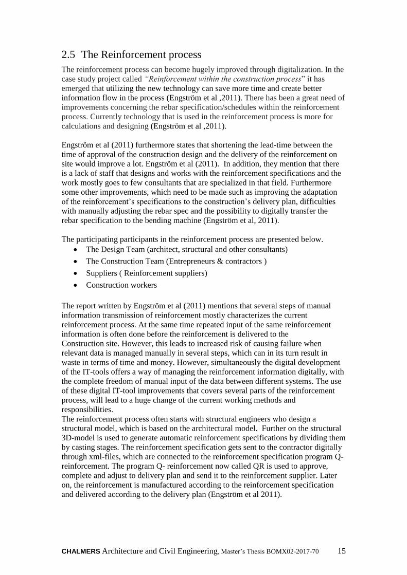
performs an additional quality control of reinforcement (Engström et al., 2011).
Figure 7 Structural engineers reinforcement processes (Engström et al., 2011).
Figure 7 explains that at each reinforcement drawing is delivered with a 3D-viewer
from the structural model. This provides the viewer a chance to clarify how the
reinforcement design looks. Simultaneously it is important that the updated
information with the correct design documentation is sent out, the green arrow
represents the digital transportations while the orange one represents the non digital
transportations (Engström et al., 2011).
CHALMERS Architecture and Civil Engineering, Master’s Thesis BOMX02-2017-70 17
The second stage in the reinforcement process is when the structural design is
handed over to the consultants, which creates the reinforcement specifications.
The Reinforcement Consultants
The consultants execute the reinforcement specifications practically by hand, after
they received the reinforcement drawings from the structural engineers. They feed in
the data into either Q or Q-spec, which now develops further to QR-data, which later
is sent out in xml-format to the reinforcement suppliers (Engström et al., 2011).
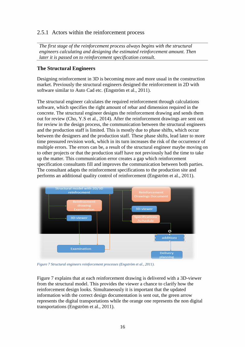
Further on BIM Alliance (2016) continues that all reinforcement information can be
managed in the QR-data. There you also can check the quality of the reinforcement,
color coding, delivery plan, the monitor status and create a report. The QR-data is
integrated to other design software programs such as Tekla and Strusoft. The figure 8
bellow illustrets how a reinforcement schedule looks.
Figure 8 Reinforcement specifications/schedule (Engström et al., 2011).
Reinforcement specification dispatch form may vary depending on the method used.
It can be sent in "dead" format, i.e. in plain paper form that requires manual
transmission. It can also be sent in PDF-format or similar digital XML file formats or
alternative cloud services. In addition, data can be carried out as reinforcement
specification regardless of, whether it is in paper or digital BIM-form in the QR-
reinforcement specification program. In order to adapt the reinforcement for
production site, it further requires digital hand laying transformation within the QR-
software. Then later the production staff can pick out the received XML files and
forward them to the reinforcement suppliers who manufacture them. This approach
creates an automated flow of armor production (Engström et al., 2011).
18
The third stage, the consultants have executed the reinforcement specifications
from the reinforcement model design. Further on they send it to the entrepreneur,
who later reviews the rebar’s documentations for the concrete structure.
The Contractor
The contractor’s engagement in the reinforcement process occurs in different stages
of the project, much depending on the cooperation and the procurement form. The
contractor provides the structural engineer with support and input on different
reinforcement solutions and adjustments concerning the production stages (Engström
et al., 2011).
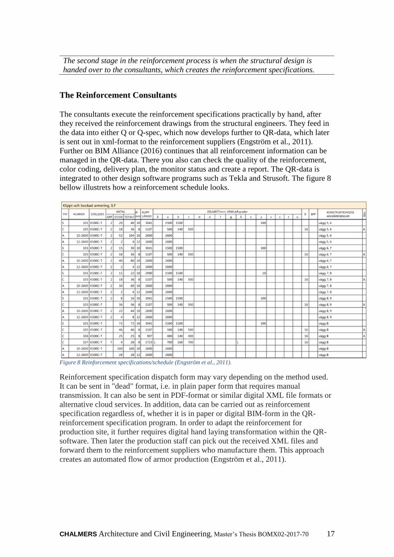
Further Engström et al., (2011) describe that the production stages are one of the
important parts of the reinforcement process, which explains and prepares the
construction site with deliveries and mountings. To facilitate the production process,
the reinforcement is divided into different casting stages e.g. concrete plate, walls,
facility one, facility two etc. Further Celsa Steelservice, (2012) continues that, to
reach an enhanced communication the casting stages are divided with different color
codes and so on by the rebar specification consultants. Color-coded reinforcement
design illustration can seen on figure 9.
Figure 9 color-coded 3D - reinforcement drawings Celsa Steelservice, (2012)

CHALMERS Architecture and Civil Engineering, Master’s Thesis BOMX02-2017-70 19
Later the contractor receives the reinforcement specification deliveries grounded upon
the specified casting stages with color-coding. The contractor currently only utilizes
paper drawings or pdf: files. The contractors do not use any digital-tools to self-
modify the rebar specifications; instead, the contractor communicates with the
designer through the phone, the colored-coded rebar is delivered as shown in figure
10 below (Celsa Steelservice, 2012).
Figure 10 Reinforcement is delivered colure coded Celsa Steelservice, (2012).
Depending on the production conditions on the construction site, the contractor
arranges start meetings with the reinforcement suppliers and discusses the production
layup and the delivery plans. This is due to every reinforcement, specification being
called-off separately while the production process progresses. The contractor often
performs quick stick sampling on the delivered reinforcement by the suppliers; mostly
due to the reception controls being time-consuming and so on. The consultant
performs the contractor requests: clear reinforcement drawings with literate facility
drawings and civil work drawings with stage classifications, color marking, end
configuration of hooks, reinforcement method (the choice between separate
reinforcement or mesh and roller rebar) (Celsa Steelservice, 2012).
20
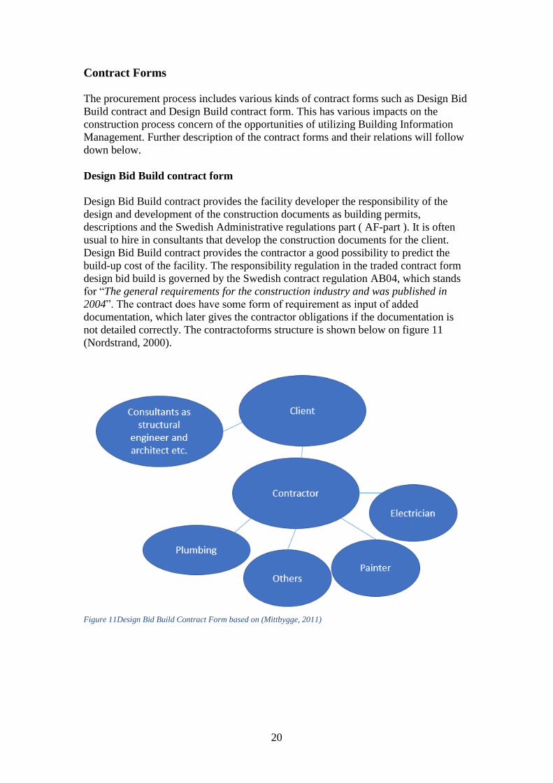
Contract Forms
The procurement process includes various kinds of contract forms such as Design Bid
Build contract and Design Build contract form. This has various impacts on the
construction process concern of the opportunities of utilizing Building Information
Management. Further description of the contract forms and their relations will follow
down below.
Design Bid Build contract form
Design Bid Build contract provides the facility developer the responsibility of the
design and development of the construction documents as building permits,
descriptions and the Swedish Administrative regulations part ( AF-part ). It is often
usual to hire in consultants that develop the construction documents for the client.
Design Bid Build contract provides the contractor a good possibility to predict the
build-up cost of the facility. The responsibility regulation in the traded contract form
design bid build is governed by the Swedish contract regulation AB04, which stands
for “The general requirements for the construction industry and was published in
2004”. The contract does have some form of requirement as input of added
documentation, which later gives the contractor obligations if the documentation is
not detailed correctly. The contractoforms structure is shown below on figure 11
(Nordstrand, 2000).
Figure 11Design Bid Build Contract Form based on (Mittbygge, 2011)
CHALMERS Architecture and Civil Engineering, Master’s Thesis BOMX02-2017-70 21
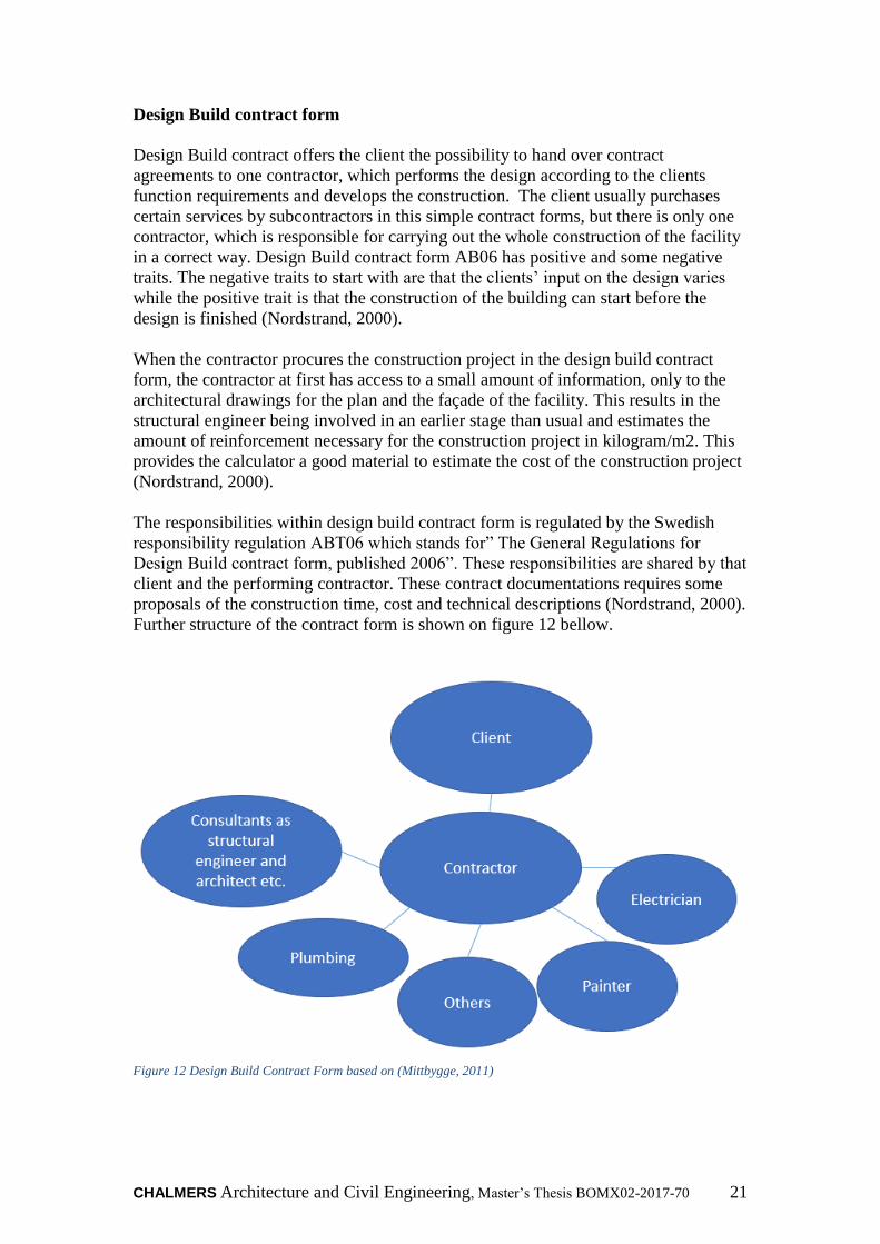
Design Build contract form
Design Build contract offers the client the possibility to hand over contract
agreements to one contractor, which performs the design according to the clients
function requirements and develops the construction. The client usually purchases
certain services by subcontractors in this simple contract forms, but there is only one
contractor, which is responsible for carrying out the whole construction of the facility
in a correct way. Design Build contract form AB06 has positive and some negative
traits. The negative traits to start with are that the clients’ input on the design varies
while the positive trait is that the construction of the building can start before the
design is finished (Nordstrand, 2000).
When the contractor procures the construction project in the design build contract
form, the contractor at first has access to a small amount of information, only to the
architectural drawings for the plan and the façade of the facility. This results in the
structural engineer being involved in an earlier stage than usual and estimates the
amount of reinforcement necessary for the construction project in kilogram/m2. This
provides the calculator a good material to estimate the cost of the construction project
(Nordstrand, 2000).
The responsibilities within design build contract form is regulated by the Swedish
responsibility regulation ABT06 which stands for” The General Regulations for
Design Build contract form, published 2006”. These responsibilities are shared by that
client and the performing contractor. These contract documentations requires some
proposals of the construction time, cost and technical descriptions (Nordstrand, 2000).
Further structure of the contract form is shown on figure 12 bellow.
Figure 12 Design Build Contract Form based on (Mittbygge, 2011)
22
The Design build contract provides the construction projects the possibility of taking
Strategical decisions concerning the projects work set. These decisions provide the
project with systematical solutions, which the consultants can take into consideration.
Furthermore, the design build contract offers construction companies which do not
have a standardized work set concerning reinforcement an opportunity to be able to
come up with solutions that fits the projects condition. The production adaptation
with the reinforcement often begins after the involved participants have agreed upon
the contract documentation. Compared to Design bid build contract, this offers the
contractor less chance to influence the construction project. The limited opportunity to
make an influence on the project often comes from the contractor’s procurement
process, which starts after the design documentations is done. However, at the same
time is it required that in design build contract that the contractor gets involved early
in the project with defining the rebar production stages and the collaboration between
the structural engineer and the contractor.
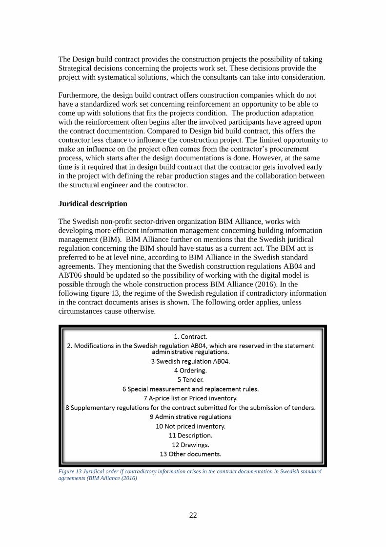
Juridical description
The Swedish non-profit sector-driven organization BIM Alliance, works with
developing more efficient information management concerning building information
management (BIM). BIM Alliance further on mentions that the Swedish juridical
regulation concerning the BIM should have status as a current act. The BIM act is
preferred to be at level nine, according to BIM Alliance in the Swedish standard
agreements. They mentioning that the Swedish construction regulations AB04 and
ABT06 should be updated so the possibility of working with the digital model is
possible through the whole construction process BIM Alliance (2016). In the
following figure 13, the regime of the Swedish regulation if contradictory information
in the contract documents arises is shown. The following order applies, unless
circumstances cause otherwise.
Figure 13 Juridical order if contradictory information arises in the contract documentation in Swedish standard
agreements (BIM Alliance (2016)
CHALMERS Architecture and Civil Engineering, Master’s Thesis BOMX02-2017-70 23
The contractor sends their document further on to the reinforcement supplier,
which handles the specification and produces reinforcement.
The Reinforcement Suppliers
Aretoulis, G. N et al., (2010) explains about an earlier observation, which describes
that price or cost is not a widely adopted criteria compared with the evaluation of the
quality performance the supplier delivers. Later on the quality criteria is followed by
delivery, price or cost and so on. Anders (2016) explains that a reinforcement supplier
is often an external supplier to the construction companies, but depending on the size
of the construction company, they sometimes have an internal supplier within the
company.
The reinforcement supplier receives the reinforcement specification from QR-data,
which later automatically reads in its information in the factories production
preparation system. To optimize the factories production system is it required that the
contractor be ahead of their time with planning and ordering of reinforcement. Mostly
because the later the order comes in to the reinforcement supplier the more of a
possibility to reach an optimized manufacturing is hampered (Engström et al., 2011).
The reinforcement supplier often quality checks that the manufactured reinforcement
suits the reinforcement specifications they have received from the consultants. Other
quality checks are often done by the supplier only when they them self-have designed
the reinforcement specification. (Engström et al., 2011)
Engström et al., (2011) mention that the reinforcement suppliers desire to e.g.
become engaged earlier in projects so they can become committed to the project as
soon as possible. Engström et al., (2011) believes that through early engagement they
have the possibility to support the production staff with questions and solutions.
What is equally important is that contractor has a good long-term planning attitude
concerning the deliveries so the manufacturing of rebar in the factories becomes as
optimal as possible. Further this will generate cost savings in the work place which is
appreciated both by the contractors and the suppliers.
24
The produced reinforcement speciation’s by the suppliers is later constructed on
put together by the construction workers in site.
Construction workers
The traditional labor within the construction process of site-casting concrete structures
still has the same similarities construction methods as previous craft-based work on
site. Furthermore do the work on the construction site contains several factors that
can require a large-scale of work, which results in that the cost of labor being almost
equivalent to material cost. At the same time has other studies shown that the labor
cost of concrete buildings was about 40% of the total cost of the building in the year
2002 (Harryson, 2002) & (Löfgren, 2002).
The association between time and money is frequent, the most time consuming
elements in the reinforcement work is the manually carried out work. The manually
carried out work is currently an urgent workmanship that includes many heavy lifts,
which are done in inappropriate work positions. This causes a poor work environment
for the construction workers and becomes disadvantageous for the construction
projects from an economic point of view (Sandberg & Hjort, 1998).
Sandberg & Hjort, (1998) continues that there is a need to industrialize the
reinforcement design so the work environment becomes improved, the time
consumption becomes shortened and the quality becomes improved. However, at the
same time mentions Sandberg & Hjort, (1998) that the best production adaption of the
reinforcement is achieved when it is adapted early at the design stage, which requires
that the structural engineer is aware of which production methods are utilized on the
construction site. In addition, some knowledge from both the architectural drawings
and the structural engineers is required so the most efficient production adaptation is
achieved (Sandberg & Hjort, 1998).
Engström et al., (2011) States that construction companies require at least some basic
knowledge of BIM. The basic required knowledge gives the employees a good
understanding of what can be achieved through BIM so the clipping from 2D to 3D is
done as smoothly as possible.

CHALMERS Architecture and Civil Engineering, Master’s Thesis BOMX02-2017-70 25
BIM usage of site-workers (BIM-kiosks)
BIM-kiosks gives site workers the possibility of viewing updated design information
of the planned construction building. According to Bråthen & Moum (2016) this
concept contributes to good communication between the site office manager and the
construction workers. Furthermore, is it mentioned that workers experienced great
advantage from using digital iPad models compared to traditional drawings. The
author also argued according to Bråthen & Moum (2016) that the building process
productivity raises when BIM is introduced to the construction-site. Their findings
also show that the workers experienced great advantages of using models compared to
traditional drawings. This potentially leads to reduced risks of costly errors and delays
on the construction site.
Furthermore, digital management of construction drawings leads to more mutual
interdependence between the various parties involved in the project. This contributes
also to a good project management, monitoring and updates on the build and planned
building. The digital model can achieve simplification of the production purchasing
process, with good material flow tracking, management and workplace disposal as
well as support with material flow tracking. Many authors expresses that the good
combination of mobile devices and BIM-kiosks, might open up interesting new
working ways in the construction site Bråthen & Moum (2016).
26
3 Method description
Will describe the research method for this thesis.
Chapter 3 begins with literature and documentation to get an understanding
the subject, later it goes through the implementation of the interviews.
3.1 Research methods
The report is conducted as a case study in Skanska’s Technical Housing department in
Gothenburg. According to Merriam (1994) a case study presents, an important
component in anthropology, psychology, sociology, work science, social work and
political science, which are utilized to systematically study events. The focus of the
research has been to conduct information of how 3D-reinforcmen can be implemented
in Skanska technical housing department in Gothenburg, at the same time evaluate the
optimal management of their reinforcement process. A study is done on how different
disciplines in the construction process work with reinforcement; The following
interviewed disciplines are structural engineers, project managers, production
managers, supervisors, district procurers with reinforcement suppliers and
construction workers.
The literature study gave a good description of how 3D-reinforcment should be utilize
theoretically and the advantages of it. The interview process started with unstructured
interviews and site visits on construction sites. As Merriam (1994) mentions, the goal
of the unstructured interviews, is in fact, to learn enough about a subject, which
makes one able to formulate questions for future interviews. Based on this knowledge,
the important information that was needed for the interviews and surveys could be
conducted.
3.2 Literature study
The literature research of the master thesis started at an early stage, through
researching on information, which was mainly obtained through two databases;
Summon at Chalmers Library and Google Scholar. Key words which gave a better
overview understanding of 3D-reinforcement were these following; implementation
of 3D-reinforcement, reinforcement schedule and the reinforcement process. Further,
the keywords was narrowed down so more relevant articles within the topic was
found e.g. BIM-uses/BIM-tools.

CHALMERS Architecture and Civil Engineering, Master’s Thesis BOMX02-2017-70 27
3.3 Skanska’s internal network
The documentation of Skanska internal network were done through selection between
relevant data for the research in their internal “Our Way Of Working (VSAA)
website”, which is Skanska Sweden's management system site. It includes their
decision and management approach, which Skanska considers leads to satisfied
customers, satisfied and committed employees, predictable and efficient operations
and increased profitability (One Skanska, 2017a)
The purpose of analyzing Skanska’s internal network was to conduct information
about how Skanska works with BIM today and how they follow up their work set
with their own reinforcement processes. One of the documents that was reviewed
was; Skanska Sweden’s ID Guide to Project BIM Implementation. The use of
appropriate data has been discussed between the author of this report and BIM
coordinating officer, about what should be emphasized in the report. Further bellow
is Skanska’s process for their designing of house projects on figure 14(One Skanska,
2017b)
Figure 14 Skanska Process Map Design of House projcets (One Skanska, 2017b)

28
3.4 Interview design
The interviews and construction site visits for this report were performed during two
weeks’ time in three different Skanska residential, office and hospital projects that
were located in these following Swedish cities Kunsbacka, Kungälv and Gothenburg.
The interview questions were designed to leave room for open answers which lead to
interesting discussions. The interviewed respondents were selected based on a list of
recommendations from the BIM coordinator of Skanska’s technical housing
department in Gothenburg. The list consists of the different interviewed respondent’s
disciplines, which is listed in Table 1.
Occupational category Companies
Structural engineer Skanska Sweden
Structural engineer Skanska Sweden
Structural engineer Skanska Norway
Reinforcement supplier Celsa Steel
Reinforcement supplier Celsa Steel
Reinforcement supplier SSI Skanska Sweden
Supervisor purchaser on site Skanska Sweden
Supervisor purchaser on site Skanska Sweden
Production manager purchaser Skanska Sweden
District purchaser manager Skanska Sweden
Project manager Skanska Sweden
Construction worker Foreign subcontractor
Construction worker Foreign subcontractor
Construction worker Skanska Sweden
Construction worker Skanska Sweden
Construction worker Skanska Sweden

CHALMERS Architecture and Civil Engineering, Master’s Thesis BOMX02-2017-70 29
3.5 Collection of empirical data
The time expectations from the interviews were approximately calculated to take
about 20-30 min with each respondent and the method that was used were the semi
structured interview form which according to Berg (2009, p.107) lets the interviewed
freely develop and elaborate their answers and explanations. Furthermore Berg (2009,
p.105) explains that semi-structured interviews gives the interviewer the possibility to
change the order of the questions and wordings. Silverman (2010, p.8-11), continues
to explain that it’s an advantage for the interviewer if they have in mind during the
interview that how they ask the question is more important than how many questions
they ask. The interviewed respondents were recorded for later transcription, which
makes it easier for the interviewer to intercept the important information and
facilitates the writing process. All respondents were informed that the interviews were
anonymous and would be submitted based on the respondent’s occupational category.
3.5.1 Transcription
The interviews where transcribed as quickly as possible to recall the appearance and
feeling the interviewer had from the respondent’s. The transcription of each interview
took about one hour per interview. The author Wallen (1996) describes the
importance of transcribing as soon as the interview was performed.
3.5.2 Selection of relevant data
The selection of relevant data has been done through selection through primary data
which interprets all previous data collected in the form of information, which has been
collected for the purpose of creating new sorts of data. The study consisted of 16
interviews. After the transcribing and selection of relevant data, the interviews were
distributed into smaller summaries based on the occupational category.
3.5.3 3D-Modelling-Tools
In this master-thesis will a test model of 3D-reinforcment ground plate and elevator
shaft be modeled. Skanska Gothenburg housebuilding project Kvibergs-Ängar will be
the first project utilizing this technology in Gothenburg, Sweden. The aim is to model
3D-Reinforcement and create reinforcement specifications at the same time visualize
the rebar will be created in the following design software programs represented on
this list. Table 2
Program version
Revit structure 2017
Naviate structure 2017
Glue- BIM360 2017
Solibri checker v.9.7
Naviswork 2016
iConstruct 2017
30
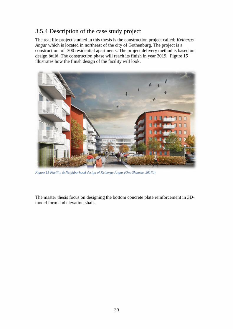
3.5.4 Description of the case study project
The real life project studied in this thesis is the construction project called; Kvibergs-
Ängar which is located in northeast of the city of Gothenburg. The project is a
construction of 300 residential apartments. The project delivery method is based on
design build. The construction phase will reach its finish in year 2019. Figure 15
illustrates how the finish design of the facility will look.
Figure 15 Facility & Neighborhood design of Kvibergs-Ängar (One Skanska, 2017b)
The master thesis focus on designing the bottom concrete plate reinforcement in 3D-
model form and elevation shaft.

CHALMERS Architecture and Civil Engineering, Master’s Thesis BOMX02-2017-70 31
3.6 Skanska: Company presentation
The construction company Skanska’s successful accomplishment up to now indicates
that Skanska is one of the major construction companies, which works for building
more sustainable societies. The construction company’s history all started in 1887
with the former name “Skånska Cement foundry” there they manufactured and
produced concrete products with great success. Later on the company had its major
climb in the international market in the midst of 1950s and onwards. The continents
Skanska has established itself in are Africa, Asia and South America where they built
power stations, roads, schools and hospitals in developing countries. However, later in
1971, Skanska had the confidence to step into the US market to build their subway
systems in New York and Washington D.C. These projects resulted in the United
States becoming one of Skånska Cement foundry’s largest markets. The company
Skånska Cement foundry changed its name to Skanska in the year 1984 (One
Skanska, 2017a).
3.6.1 Organizational view of Skanska
Organizationally Skanska did develop more in the 90s, which resulted in the doubling
of sales in a short period. The organizational development was the acquisition that
made Skanska AB one of the major global companies.
Skanska changed its strategy later in the 20th century; there they focused more on
developing and constructing residential and commercial properties. Also constructing
infrastructure projects in their home markets in Europe and the United States. At the
same time as the home market, continued developing, the safety aspects and work
environment criteria has become more important. To achieve these work
environmental goals Skanska has put its weight on ethics, achieving zero occupational
accidents and putting sustained social development into focus (One Skanska, 2017a).
3.6.2 Building Information Management (BIM) within Skanska
Skanska vision is that BIM (Building Information Management) will provide them a
good opportunity to gather information and create a common information source (One
Skanska, 2017a). Through digitalizing the design and administration process they
believe that all unnecessary waste of paper for drawing would be avoided. Through
saving, the natural materials by using digital equipment they believe this will contribute
to creating a more sustainable society. As well as digitalization will create better flow
in the production stage by reducing all the unnecessary interruptions in every project
line. Globally Skanska has a constant development within BIM where colleagues gather
with the purpose of sharing experiences. Furthermore, Skanska explains (One Skanska,
2017a) that BIM has its advantages such as utilizing it in work preparation and safety
planning, quantity removal and improving communication between all project-involved
participants.
32
4 Results
The results chapter aims to present the study's research section. The first results part
is broken down by occupational categories and issues related to the reinforcement
process. The second result part is divided according to the various digital processes
that exist within the reinforcement process. The chosen heading aims to create a red
thread between theory, results and analysis.
4.1 Interview results
The perspective of the actors within the reinforcement process is presented in the
interview results chapter. The results themes are based on the thesis research
questions. The presentation of the results describes how and in what way the current
reinforcement process looks.
4.1.1 Skanska Sweden Structural engineers current work set
Collaboration between the various disciplines in the reinforcement process
Utilizing 3D-reinforcment in construction projects often depends on the construction
projects design and the demands requested in the project. If the construction project
requests utilizing the 3D-reinfrocement, the structural engineers often design with
traditional 2D-drawings. Later the traditional 2D drawing are handed over, to another
structural engineer, who is responsible for designing the reinforcement specifications
in 3D with casting stages. 3D-reinforcment is in the current situation designed mostly
for visualization purposes in other technical departments within Skanska.
Then structural engineers start their design process by calculating the carrying load of
the structure and estimate the basic soles before they utilize the reinforcement for the
structure and design it in traditional 2D drawings. They often design the 3D-
reinfrocemnt, mostly depending on if the project wants to utilize 3D-reinforcement or
not. Afterwards the 3D-model or designed drawings are sent to the construction site,
there they order the reinforcement from their suppliers. Depending on how much
support the construction site desires or its conditions, the engineers are always helpful
with that support.
Construction Projects are often similar but rarely identical which makes the
reinforcement process unique. However, the structural engineers mention that in the
design phase, if they have the opportunity, they utilize some design parts or work sets
from previous projects. Through adjusting some parameters the reinforcement design
can become more general. The structural engineers mention also that they believe that
utilizing more standardized work procedures would lead to an improved
communication between them and the project managers on the construction site. This
is partly due to, better visualization of the design requests from the project managers.
The program software, which are utilized mostly for designing 3D-reinforcement, are
Revit, Tekla and Solibri. Concerning quality controls of the reinforcement design, the
models are checked 2-3 times before they hand them over to the construction site
production staff.
CHALMERS Architecture and Civil Engineering, Master’s Thesis BOMX02-2017-70 33
Suggestions on improvements in the reinforcement process?
The structural engineers considers that the communication between all de different
disciplines can hopefully become more improved through utilizing the same
communication systems (cloud). If they design in program software Revit or Tekla
they have the opportunity to upload it in the same shared cloud.
Advantages / disadvantages with 3D reinforcement in the reinforcement
process
The conditions to use 3D reinforcement are beginning to look brighter than they did
before. Previously, the round shaped elements were a challenge to design with 3D
reinforcement but recently it has become more useful. While modeling with
rectangular and square shapes has worked excellently. The structural engineers would
like to find a way to simplify the 3D design of reinforcement so its design process
becomes more optimal.
The advantages 3D-reinforcement has is that it gives the user the opportunity to find
and visualize all the strange cuts and at the same time it gives another opportunity to
get all quantities of it, so they are able to calculate the project cost of the
reinforcement.
The disadvantage is that the knowledge with designing 3D-reinforcement is small and
the design program Revit has become good but not enough for designing in 3D. The
use of 3D reinforcement in construction projects is up to 30% while compared with
traditional 2D reinforcement, which is used up to 70% of the designing process.
The structural engineers prefer to have better contact with the construction sites
production staff. So the misunderstandings are prevented which usually take place.
The structural engineers wish to have an earlier cooperation with the production staff
so they get a better picture of the project and prevent extra work on the construction
site. At the same time the structural engineers become better at designing the 3D-
reinforcment so it becomes more adapted to the construction site.
34
Current Working Methods
Currently do the structural engineer perform overdraft calculation of the
reinforcement cost in the software programs Solibri, which allows them to estimate
how much cost they will put on the projects reinforcement procurement. Further on is
their communication limited with the construction workers and often governed by the
projects procurement form. Depending on the project design do the productions staff
contact the structural engineers; otherwise do they handle the reinforcement process
by their own. Current possibilities of visualizing reinforcement work are good but
could be better.
Software Comparison between Revit and Tekla
All the structural engineers mention that the Autodesk design software program Revit
is progressing and becoming more suitable to design 3D-reinforcement. The benefit
with 3D visualization is that it gives the viewer a chance of easily obtaining c / c
distances in a simple manner while knowing the number of reinforcing rebar iron that
should be on the position with the right chap length and radius booking etc. Compared
with the 2D-design where users need to run practical calculations for getting the
information that 3D-design offers. If any changes occur 3D-design offers an update
on the information and design modifications shared with the design. In addition, the
amount of rebar has specific identification numbers, that gives information about
which casting stage it belongs to. Revit is customized more for house construction
buildings while Tekla is more unspecified and has larges design opportunities, where
you can design bolts, bridges, steel buildings and foundations. Tekla has an open
approach to BIM there you can run fabrication machinery. But what Tekla and Revit
has in common is that both have access to the Scientific program Q-reinforcement or
QR plugin which allows the designers to have the opportunity to organize their lists
and project components and save them directly in QR. The scientific program
supports export of-cut and bent rebar, special types of rebar and rebar welded baskets.
The time difference with designing 2D or 3D differs, they mention that the project
conditions and the design knowledge of the structural engineer sets up the time
duration of the design. The structural engineers mention also that designing 3D-
reinforcement has shorter time duration when it comes to designing smaller projects.
Furthermore, in larger projects it may take less time with 2D-design compared to 3D-
reinforcement.
CHALMERS Architecture and Civil Engineering, Master’s Thesis BOMX02-2017-70 35
4.1.2 Skanska Norway Structural engineers current work set
Skanska Norway has digitalized their way of carrying out their construction process
and is currently performing their project without traditional paper drawings.
The digitalization of their reinforcement process often start with that their structural
engineers creating 3D-model of their reinforcement work in DWG: file formats. For
planning production adaptations and casting stages the structural engineer
collaborates with the production staff on the construction site. Later on they receive
feedback on their 3D- reinforcement model and produce the reinforcement schedule
through collaborating with their supplier by using the software program Solibri Model
checker.
To also have an opportunity to visualize the 3D-reinforcement work on the
construction site the structural engineers use Glue-BIM 360, the cloud service that
shows the reinforcement work to the production staff and the construction workers on
the construction site. Through Glue-BIM 360 the construction workers communicate
directly with the structural engineers, by just commenting edit on their IPad/tablets.
The conditions for using 3D-reinforcement are good and Skanska Norway has now
used it for about a one year period in seven different projects. They have experienced
that the digitalization of the reinforcement processes delivers a higher quality and
goes faster than traditional paper work. In addition, it provides a better underlay for
their design process, which saves time and money in every line of the projects.
The advantages with digitalization of the reinforcement work is that it gives all the
project participants a better understanding and an opportunity to start earlier in the
process. This is an especially useful for the production staff, who comes up with
important tips on production adaptations. 3D-reinforcement saves the structural
engineers up to 50-70 percent time on their reinforcement process.
The structural engineers use these following software programs to design and work
with in the reinforcement process; Revit, Solibri, the plugin program Iconstruct for
Navis Works and Glue BIM 360.
36
4.1.3 Skanska Sweden Procurement /Contractors
Collaboration between the various disciplines in the reinforcement process
In order to keep the production work fluent the purchasers who suborder
reinforcement at Skanska Gothenburg Building department plan the reinforcement
work along their working schedule. The supervisor or the production managers are
often the ones that manage the procurement of reinforcement on site. However,
dependent of the project design and conditions they have the opportunity to get
support from their central purchaser in their company. Their central purchasers are
often a central district purchaser that provides the site managers, with support of
interpreting and estimating the projects framework agreements and cost managing the
project. The reinforcement purchases made today are mostly roller rebar
reinforcement, straight iron, reinforcement baskets, and IFL / cut, bent reinforcing,
and even prefabricated rebar.
The reinforcement process is partly dependent on how the production processes are
carried out on the construction site. While its procurement processes depend on which
procurement form is utilized in the project, the various general procurement forms are
Deign Build and Design Bid Build contracts which set different project conditions.
The contract form, Design Build gives the various disciplines involved in the project
better communication opportunities through whole chain compared to Design bid
build contract. The Design Build contract involves all the project participants in an
early stage, which contributes to the project productivity. The participating disciplines
involved in the reinforcement process are the structural engineer, carpenter,
supervisor, production manager and the central district purchaser as well as the
reinforcement supplier. Through support of the report called NPU, (Skanska Nordic
procurement unit) the district purchaser estimates the reinforcement cost that they
most regularly buy from their suppliers. Skanska has framework agreement with their
own supplier SSI and their external supplier Celsa Steel AB. These following
frameworks, give Skanska the great opportunities to geographically choose cost
beneficial reinforcement suppliers for their projects. At the same time Skanska’s
house procurement department have a close collaboration with their own technical
department, which provides them with good basis on how the reinforcement is
planned and customized in the production.
All respective interviewees from the purchasing side states that they agree that the
reinforcement is procured quite project specifically, but they mostly encounter similar
processes with different degrees of difficulties on the construction site. However, the
purchasers on the construction site expressed desire of simplifying the practical work
in the workplace for the construction workers so the heavy workload of the
reinforcement decreases.
CHALMERS Architecture and Civil Engineering, Master’s Thesis BOMX02-2017-70 37
But most quality checks on the reinforcement are performed by Skanska’s
reinforcement suppliers, but the most checks which are done by the purchasers are
more to ensure that the delivery order sent matches the requested orders. The
construction workers examine the rebar’s length, dimensions and distance so they
have access to the right reinforcement. The software program used mostly by the
supervisors that the procurement on the construction site is Tekla’s own iPad program
BIM-sight.
Suggestions on improvements in the reinforcement process
Some improvements requested by all interviewed respondents are that the structural
engineer draws more production fitted drawings, which suit more to how things are
practically built and so the rebar is do not get crowded and end up in the wrong layers.
In addition, the file export and import of models between the structural engineer and
the reinforcement supplier could have be improved so they are co-coordinated. The
purchasers on the construction site would also like to improve their communication
with the structural engineer regarding revisions and changes that occur in the work
place and with the drawings so they do not need to wait months before getting
support. A request from all purchasers has been for more meetings between all the
different disciplines involved and with more frequent follow ups so improvements in
the reinforcement processes occurs.
Advantages / disadvantages with 3D reinforcement in the reinforcement
process
The advantages mentioned by the following purchaser with 3D-reinforcement is that
it gives the structural engineer the possibility to adjust rebar designs before handing
them out to the production site. Another advantage, which is well appreciated, is that
the supervisors need less time to manage the reinforcement work and the construction
workers get the opportunity to bring out their iPads with them so they can understand
their reinforcement work better. The 3D-reinforcement adds better visual holistic
pictures of the complicated reinforcement areas in the construction e.g.
reinforcement’s clashes, casting splice etc. it also gives the unexperienced but more
technically knowledgeable production staff and construction workers better
understanding of the reinforcement drawings .The disadvantage the purchasers
mentioned is that designer and reinforcement supplier poorly promote the 3D-
reinforcement. Another well-appreciated function that the 3D-reinforcement offers the
purchasers is the possibility to receive digital information about the reinforcement
which they can cost-estimate the projects with.
The current conditions for 3D-reinforcement are good and the request of visualizing is
high, but could have been better if we started utilizing it more on projects, so that their
technique and the operation of it becomes improved and more time saving. However,
the utilization of 3D-reinforcement has been limited partly due to software program
complications and unexperienced production staff.
38
Current Working Methods
The supervisors and the production manager receives 2D drawings or 3D-models
through their central project share centrals and often the deliveries come through
distributed production stages. The district purchasers get involved with production
adaption of the reinforcement work through supporting the production staff with
procuring reinforcement from their suppliers. The production staff determines,
depending on available workforce if they will perform the reinforcement work
practically or order pre-manufactured reinforcement to the construction site. Later the
cooperation with the structural engineers mainly depends on which contract form the
project is procured or if they are internal or external structural engineers. If the project
is utilizing their own structural engineers, then it will become much cheaper, in terms
of the construction cost stays within their own company.
The work coordination with the construction workers can differ depending on the
documents the production manager has access to. If 3D-reinforcement is utilized, then
the coordination with the construction workers is done in the sheds with a flat screen
that visualizes the project in 3D-models. Sometimes depending on the project
complexity the construction workers have usage of iPads that they bring with them
outside on the construction site. While traditional projects with 2D-drawings are held
in similar ways but with, 2D drawing on paper form and which often remains in the
sheds.
Contract form that promotes 3D-reinforcement.
The most appreciated contract form by all purchasers overall is Design Build contract.
In this contract form they have the possibility to request better demands by the
structural engineers and govern the reinforcement process in a more suitable way. The
Design Build contract offers the purchasers lower risk with delays if changes should
occur with the design. While in Design Bid Build contract the risk for delays is
potentially higher, due to that structural engineers often might start working with
other projects. The reinforcement is purchased through the Swedish general
requirements for purchasing of material goods in commercial construction ABM07.
Otherwise the purchaser considers the 3D-reinforcement more profitable in larger
projects than smaller ones and also that the possibility to have the 3D-models sent
with the reinforcement specification is more time saving then getting them separate
paper forms
CHALMERS Architecture and Civil Engineering, Master’s Thesis BOMX02-2017-70 39
4.1.4 Internal & External Reinforcement Suppliers
Collaboration between the various disciplines in the reinforcement process?
Skanska’s external reinforcement supplier Celsa Steel AB works in a similar way
regardless of their geographical operation. Mostly they prefabricate, bend and order
their steel abroad from their own Scandinavian steel workshops. Then later their
technical sales men utilize their framework agreements or search for new different
projects. When their sellers meet their clients they often start with having an
overview over the 2D-drawing then later have short introduction there they leave
suggestions on different methods they can work with the reinforcement. The
discussion can be about everything from deciding if they will utilize roller rebar’s on
the base plate, welded elements in fundamentals or in the edge beams and specially
designed nets so the production time gets more optimized. After the production staff
has decided roughly which reinforcement products they need to utilize, the work is
handed over to their own technical departments, which start designing the special
products that they receive through Pdf (2D) drawings or (3D) models DWG: files
formats. Through early formation, the rebar specification list shapes the projects
reinforcement process. Their technical department has often a long dialog with the
structural engineer so they can simplify the design and the construction process.
Skanska’s internal technical reinforcement support/supplier SSI has similar process as
Celsa Steel with their suppliers abroad in Poland. SSI supplies Skanska with
significantly lower costs than their Nordic domestic ones. Since SSI Skanska is a
technical support which is an intermediary between project and suppliers abroad,
they focus more on invoices and placing orders with deliveries so they arrive on time.
Standard processes
Most of Celsa Steels reinforcement processes in their projects are unique, their
projects can sometimes vary from e.g. a simple villa flats to more complex bridge
constructions. It can also vary from a waterproof residential building with rebar in the
floor slabs etc. They always assume from the unique project and try to find solutions
that suit them through utilizing previous experiences from earlier projects. While SSI
mentions the same as Celsa Steel, that their reinforcement projects also are unique and
that they tries to utilize previous experiences. However, SSI mentions also that what
always varies in projects are the design interpretations from the structural engineers
and their work preparation.
Celsa steel have a standardized workflow where they have sellers, which are out as
early as possible to discuss what the workplace desires. In addition, workplace
meetings, designing and making templates so their clients are able to go through the
standard questions, so their technicians do not need to call around. However, Celsa
Steel mentions that they are able to standardize certain reinforcing products, usually
on the welded projects basket if it is an edge beam. 3D reinforcement is used mostly
in major projects.SSI utilizes a same call-off template so misunderstandings become
reduced. Their template is an excel-sheet, which is printed out as a pdf; there is a box
for desired delivery time and confirmed delivery time. For the moment, they utilize
IFC-file format as export and import tool.

40
Cooperation
To improve the 3D-reinforcement cooperation, SSI and Celsa mentioned that the
various disciplines to come together at an early stage and have a dialogue about how
3D reinforcement and its communication needs to be improved.
Celsa Steel wishes that the reinforcement call-offs are done more digitally instead of
through the phone. At the same time they want to create a shared data network where
all the designer revisions are easily visible, so the construction site as well as the
reinforcement supplier easily can get an update on the design .A common database
will lead to a better communication between the construction site, designers as well as
suppliers.
Quality
The rebar suppliers admit that they perform quality checks of the reinforcement
supplies before the reinforcement specifications are done. They also perform tests of
steel, tensile strength and the digitized around the ridge area, re-bending
sustainability, crack formations and so on. Controls done by the receiver are
extremely rare because it is difficult to control several tons of rebar. The recipient of
the reinforcement delivery, usually just sign the paper and then solve it on the spot if
there are any difficulties or the supervisor contacts them again. Partly the construction
workers carry out the visual assembly inspection with c / c distance. Celsa Steel also
mentioned that they have ISO 14001-quality certification.
The reinforcement suppliers utilize Tekla BIM-sight visualization software where
they have the opportunity, to locate themselves in their field easily and Tekla main
modeling program which can handle IFC and DWGs files. Connected to Tekla we
have QR Celsas Steels own developed program that acts as a cloud service to their
reinforcement specifications. QR provides the reinforcement suppliers a planning and
delivery program.

CHALMERS Architecture and Civil Engineering, Master’s Thesis BOMX02-2017-70 41
Suggestions on improvements in the reinforcement process?
SSI are trying to standardize their approach. In every project, they want to utilize
more of Standards building models, so that the designer and the reinforcement
supplier projects are more designed alike .This is mainly because in the current
situation is all the designs drawings on the same way but not likewise. Celsa Steel
mentions that they want to utilize an approach that can streamline the time element
with reinforcement projects. This is primarily done by having meetings where all the
disciplines involved in the early stages of the project and discuss what is important to
utilize in the workplace. This sort of meetings gives the project the opportunity to
earn money and time on communication on the most optimal possible way.
At the same time Celsa Steel wants more long-term partnerships between Skanska and
them, which offers both an opportunity to design and work with more central
discussions in the current situation about the design. Instead of just utilizing their
current central price discussion with their purchasers.
Celsa steel mentions that they wish to have someone they can discuss delivery
schedules and find a way where they can standardize the reinforcement process. Celsa
Steel mentions that they have a similar collaboration with other contractors where
there is discussion of how the reinforcement must be marked, how they should deliver
reinforcement. In addition, where they usually get a description of how entrepreneurs
wishing to get reinforcement delivered.
Utilizing, a central discussion may result to new approaches and concepts can which
can be tried. Central discussions may leads to a more developmental cooperation.
They also want more transparency in the projects in the case that they want more
integrated digital timetable so they see how it is in the projects.
Celsa Steel also want a more advanced process tools with digitized communication
networks where a lot of communication in the current situation is via phone and
email. This gives Celsa Steel the opportunity to put their order in the workplace-
digitized schedule so the supervisors can see more easily, what is in stock and so on.
This will lead in is turn to the creation of a better policy which then Celsa feed on
delivering good products, they deliver today without knowing about how Skanska
wishes to have it. By having a shared network, can they have more joined supplies

42
Advantages / disadvantages with 3D reinforcement in the reinforcement
process
3D-reinforcement offers much more quality controlled reinforcement it is easier to
visualize the errors for those who perform the reinforcement specifications and those
who builds it. The disadvantage that it takes more time to make 3D-modeled
reinforcement compared to 2D-reinforcement.
A disadvantage with today’s current work set with 3D-reinforcement is that they do
not early utilize a product list that regulates the reinforcement work so double work is
avoided by structural engineers and designers. Another downside is that the
knowledge in BIM is small in Sweden and that we have not come that far with it so
everyone knows how to work with it compared to our neighbor Norway.
Pre-conditions with 3D reinforcement can vary a bit, mostly depending on the
opportunities that there are for projects and their work-set. The early directives play a
major role, since three years ago. The supplier tried to push the construction site to
utilize the new technology while today we notice that construction sites asking more
about 3D models. However, the usability of the software program earlier had
technical complications with Tekla and Revit. However in the course of the
technology getting better, it becomes faster to work with 3D reinforcement then
earlier work sets. The 3D reinforcement cost is higher than 2D when their price range
is lower than usual because they want people to exploit technology to cost-effectively
possible. It takes more time to draw in 3D than 2D while the cost is higher when
counting it home. But if workplaces and suppliers had worked together better with 3D
reinforcement to create better value to it so it would have gone better when all the
conditions are there on the spot.
CHALMERS Architecture and Civil Engineering, Master’s Thesis BOMX02-2017-70 43
Current Working Methods
Celsa Steel wishes to get their reinforcement specifications by their self-developed
web-based database called Q-R, which is utilized for different reinforcement products.
Their self-developed database is and plugin software for Revit and Tekla. Otherwise,
do they usually hunt for DWG: files on the drawings they receive in PDF forms by
their clients. While SSI work as a technical support for Skanska and their
reinforcement suppliers in Poland and the Baltic countries. SSI orders mostly with
DHL shipping company and supports with reinforcement transport and technical
issues.
Adapting the reinforcement deliveries with the construction sites conditions and
requirements is done in the manufacturing stage so it prevents errors in the delivery
phase. Celsa Steel uses its delivery data networks in their self-developed Q-R
software where the delivery status is available. They also have access to an internal
scanning system used for sortation of the reinforcement before it’s placed in the
trucks. They also conduct visual inspection of the reinforcement before they later
allow the work place organizes the work on the construction site.
Usually does the reinforcement supplier adapt their work set after the available
information they have access to from the construction site and their designers. Then
after that, is the reinforcement sorted up and marked up in different colors depending
on which building group they belong and casting stage. The reinforcement orders are
checked in with the projects timetable, which usually is established in the beginning
of the projects. Through early collaboration with the entrepreneur, do they believe that
reinforcement supply can become more effective right away. SSI has the same price
range on the reinforcement specifications costs, compared to Celsa Steel where it
costs more to with reinforcement specifications through 3D reinforcement than 2D.
Celsa Steel mentions that they plan their concrete casting in different production
stages, which they design through the software program Tekla, there they outsource
reinforcement specification lists. When the delivery schedule and casting stages is
determined do they send over all finished reinforcement lists and drawings, which
show what order they assemble the elements or how they deploy the rolling armor,
and where the reinforcement net will be set. After that requirement from the
construction site is met and approved by them, do they only have delivery of the
product left. They perform add ones on the reinforcement where they draw the rebar,
welded elements and special nets.
44
The reinforcement suppliers usually receive 3D-concrete models without the
reinforcement from the structural engineers. Most partly to that, the structural
engineers often used to send concrete models in 3D and detail design the
reinforcement in 2D. However, later in time has the structural engineers started
including the reinforcement in the 3D-concrete models, which has added to us that we
adjust or remove portion of the reinforcement because it is not always the structural
engineer’s designs on the right way. Often do their reinforcement design require ads
in there welded elements and rebar nets. The reinforcement suppliers prefer mostly to
receive the concrete model, without 3D-reinforcement included.
Because of the adjustments often takes long time and if the structural engineer utilizes
Revit and export through IFC to Tekla do they often encounter compatibility issues
with the 3D reinforcement. Celsa Steel mentions that it is easier for them to utilize the
concrete model and design with software programs like Tekla’s concrete units or
receive the reinforcement specifications through their own developed database Q-R.
Design options with 3D-reinforcement?
All reinforcement suppliers admit that they usually adapts their work to their
customer’s requirements and uses software products, which suits them. Their clients
appreciate the possibility to being able to visualize in 3D. All suppliers prefer to share
in the IFC file format mostly because it offers them a smooth software transition, IFC
is an open file format, which can be utilized by most software programs. They wish to
gain better insight into workplace delivery schedules that govern and plans the
reinforcement work. Mostly because they want to avoid that such info will come at
the last minute.
CHALMERS Architecture and Civil Engineering, Master’s Thesis BOMX02-2017-70 45
4.1.5 Skanska Sweden Construction Workers
Collaboration between the various disciplines in the reinforcement process?
The construction workers way of working with reinforcement in the present situation
is that they utilize 2D-designed reinforcement for cut and bent reinforcement, which
their reinforcement suppliers deliver to them.
In the reinforcement process, has the construction workers mentions that it always
depend on which time in the process they get included. If they are involved early in
the process do they have the chance to be involved in the discussions with making the
project as cost effective as possible e.g. the selection between using C-clamps instead
of another kind of reinforcement bracket. In addition, which can be made differently
and fastest or what they should prefabricate.
Further on do the workers tell that the reinforcement process are project unique with
varying experiences on the construction workers on the construction site. Many
workers usually come with new and old idea’s that might work as well. Many of the
older generation workers prefer 2D-drawings compared with the younger generation,
which easier catches up the new technologies. They mentions that the older
generation has a better overview of the whole project with 2D-design reinforcement
instead of 3D-desinged reinforcement. The file size, the design functions and the
communication with the other involved in the process are crucial for the
reinforcement process.
The construction workers desire more simplified drawing, since many of the new
workers possess a minor 2D-reinforcement drawings knowledge compared with the
older generation. Utilizing more of standardized reinforcement work set world favor,
the construction time allot.
The construction workers collaboration with the other disciplines in the reinforcement
process varies. Usually do they work with the sit manager, production manager and
also the reinforcement suppliers and structural engineers in various different ways.
Mostly do they plan their work with the site and the production manager but
sometimes also the reinforcement suppliers. The communication varies depending on
if; their supplier is from abroad or domestic. Some workers mentions that
communication with the production manager is sufficient for them most of the times
but that they appreciate if the structural engineer could be involved more so if errors
occur, it could easily be solved.
The supplier often insures the quality check of the reinforcement so it holds its
standards. There are also done a practical checking’s by the construction site workers,
which compares the amount of information written in the reinforcement specification
with the delivered order. The visualization program the construction workers uses are
Tekla’s own site software BIM-Sight.
46
Suggestions on improvements in the reinforcement process?
The conditions for utilizing 3D-reinfrocemnt are variable and often depend on the
design of the project. So far has the 3D-reinforemnt been used mostly in house-
projects. The construction workers mentions that it depends much on the pre-
knowledge that the construction workers has but that it usually takes up to two or
three weeks to learn working with 3D-reinforcement. They also mention that the 3D-
visualization gives more information than the 2D- drawings and that this facilitates
the language difficulties for foreign construction workers and does not require great
knowledge of 2D-drawings for the newer construction workers.
The construction workers desires to have more experienced structural engineers,
which are more able to support them with adjustments of complicated changes that
might occur. They also desire that the structural engineers are able to be with them on
the construction site, they believe that it would facilitate dialogue and give it a better
chance to get a faster response if something comes up. In this way can they avoid
managing and adjusting themselves in sheets into the changes. Otherwise, they bring
their experience with them from previous projects with solving complicated
adjustment.
Advantages / disadvantages with 3D reinforcement in the reinforcement
process
The benefits that numerous construction workers mention is that they appreciate that
at the early stage of the project being able to predict if it will occur any collision
clashes or not. The disadvantages they mention is that there is too much detail of the
reinforcements, so it becomes difficult to see, sectional and elevation views and
fragility of the iPad used to visualize the construction site today. Professional workers
wish that the visualization of information on the tablet could come up in text from on
the side of the object, so you do not need to count bars and so on. Another goal is the
iPad's digital programs toolbar becomes more optima so that it complements and
simplifies 2D drawing for the younger construction workers with less experience and
knowledge.
The desire to visualize the reinforcement by the construction workers are varies but
they think its fun and are gladly with keeping up with the progress of the digital
developments. They also explained that it makes it easier for them to understand what
is possible and impossible and creates a safer workplace for the workers.
CHALMERS Architecture and Civil Engineering, Master’s Thesis BOMX02-2017-70 47
Current Working Methods
The workers answers that the 2D drawing do not give them enough information so
they need sometimes to utilize 3D designs on their iPads as a complement. Their
production managers, suppliers and structural engineers usually predetermine their
production plan with casting stages and color codes of the reinforcement. The
reinforcement rolls are usually marked with specific numbers, which can be found on
the 2D-drawings. In the current stage do the construction workers utilize the 3D-
reinforcment as visualization guide only. The Most cooperation and contact they have
with the structural engineers is usually through their production managers.
Design options with 3D-reinforcement?
The construction workers desires their simulation of 3D reinforcement on their IPad,
becomes more improved graphically and that it contains more information e.g.
reinforcements numbers and so on. The construction workers wishes also that the
IPad became more resistant to conditions that are out there on the construction site.

48
4.2 3D-Modelling results
This chapter will visualize the achieved 3D-reinforcement design results. The project;
Kvibergs Ängar, which earlier has been presented in the method part is the first
project Skanska Gothenburg technical department will perform 3D-reinforcement
design with. The results, which been from this master thesis, have been execution of
two different kind method to produce reinforcement schedules, which can be utilized
in the software program Revit 2017.
The first method is more of a traditional one; there the reinforcement schedule is
executed in the software plugin program named Q-reinforcement (Q-armering). The
other method is through exporting out the design in an IFC-export to the collaboration
software program Solibri v9.7 and color code the rebar’s ,divide them in different
casting stages and visualize them etc. On the figures, 16 bellow do we have the
opportunity to visualize and see how the process looks from the structural engineers
design table to the construction site.
The Design Phase- part One, Overview of the project model.
Figure 16 Kvibergs Ängar Revit 2017 Modell
All concrete elements, which are not prefabricated in this project contains 3D-
reinforcement. The bottom plate and the elevator pit with the electrical pit are does
which are designed with 3D-reinforcement. This master thesis will only focus on how
the 3D-reinforcement design of the elevator pit is scheduled.
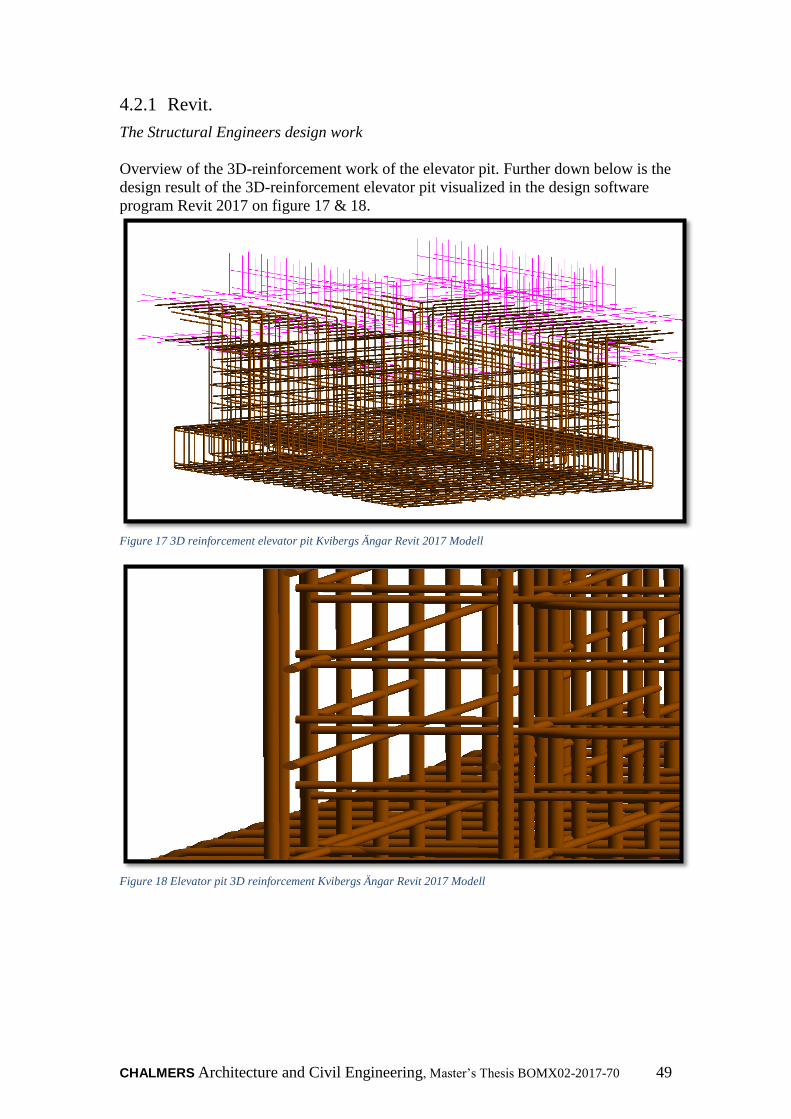
CHALMERS Architecture and Civil Engineering, Master’s Thesis BOMX02-2017-70 49
4.2.1 Revit.
The Structural Engineers design work
Overview of the 3D-reinforcement work of the elevator pit. Further down below is the
design result of the 3D-reinforcement elevator pit visualized in the design software
program Revit 2017 on figure 17 & 18.
Figure 17 3D reinforcement elevator pit Kvibergs Ängar Revit 2017 Modell
Figure 18 Elevator pit 3D reinforcement Kvibergs Ängar Revit 2017 Modell
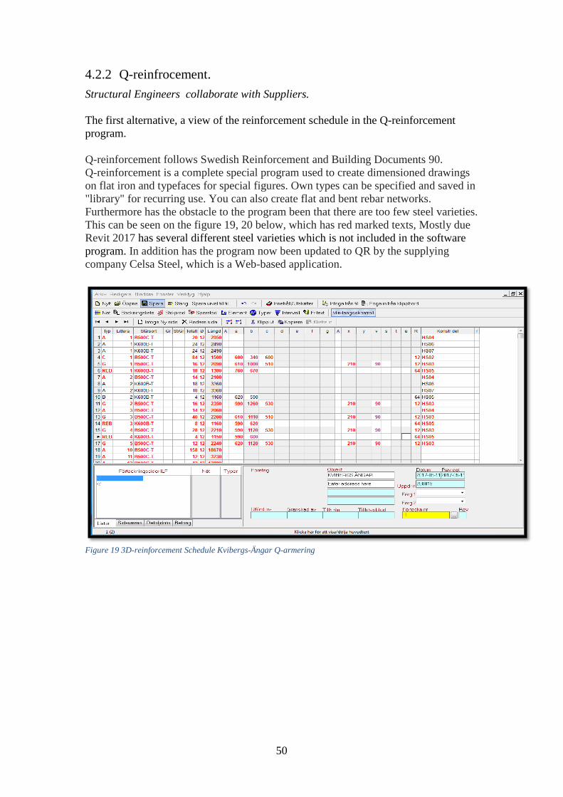
50
4.2.2 Q-reinfrocement.
Structural Engineers collaborate with Suppliers.
The first alternative, a view of the reinforcement schedule in the Q-reinforcement
program.
Q-reinforcement follows Swedish Reinforcement and Building Documents 90.
Q-reinforcement is a complete special program used to create dimensioned drawings
on flat iron and typefaces for special figures. Own types can be specified and saved in
"library" for recurring use. You can also create flat and bent rebar networks.
Furthermore has the obstacle to the program been that there are too few steel varieties.
This can be seen on the figure 19, 20 below, which has red marked texts, Mostly due
Revit 2017 has several different steel varieties which is not included in the software
program. In addition has the program now been updated to QR by the supplying
company Celsa Steel, which is a Web-based application.
Figure 19 3D-reinforcement Schedule Kvibergs-Ängar Q-armering
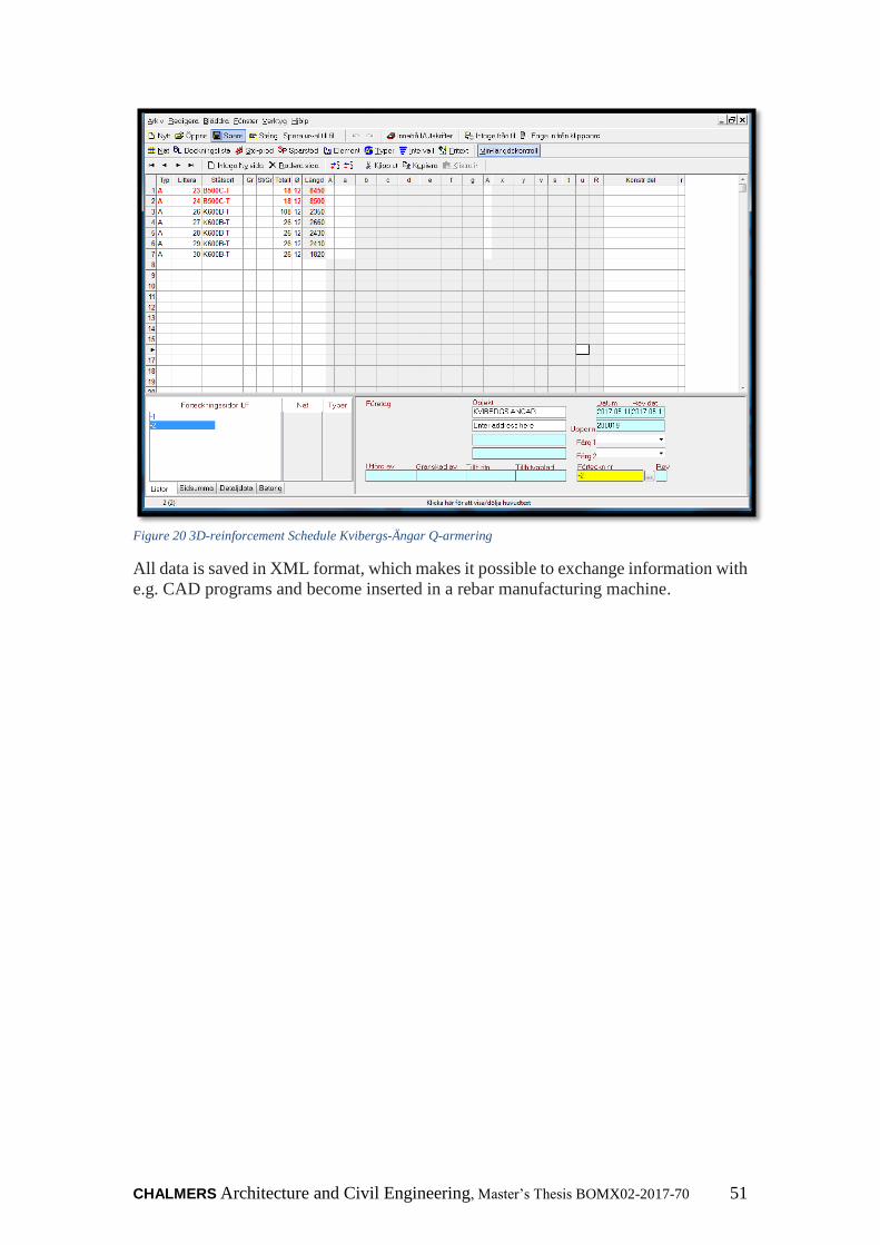
CHALMERS Architecture and Civil Engineering, Master’s Thesis BOMX02-2017-70 51
Figure 20 3D-reinforcement Schedule Kvibergs-Ängar Q-armering
All data is saved in XML format, which makes it possible to exchange information with
e.g. CAD programs and become inserted in a rebar manufacturing machine.
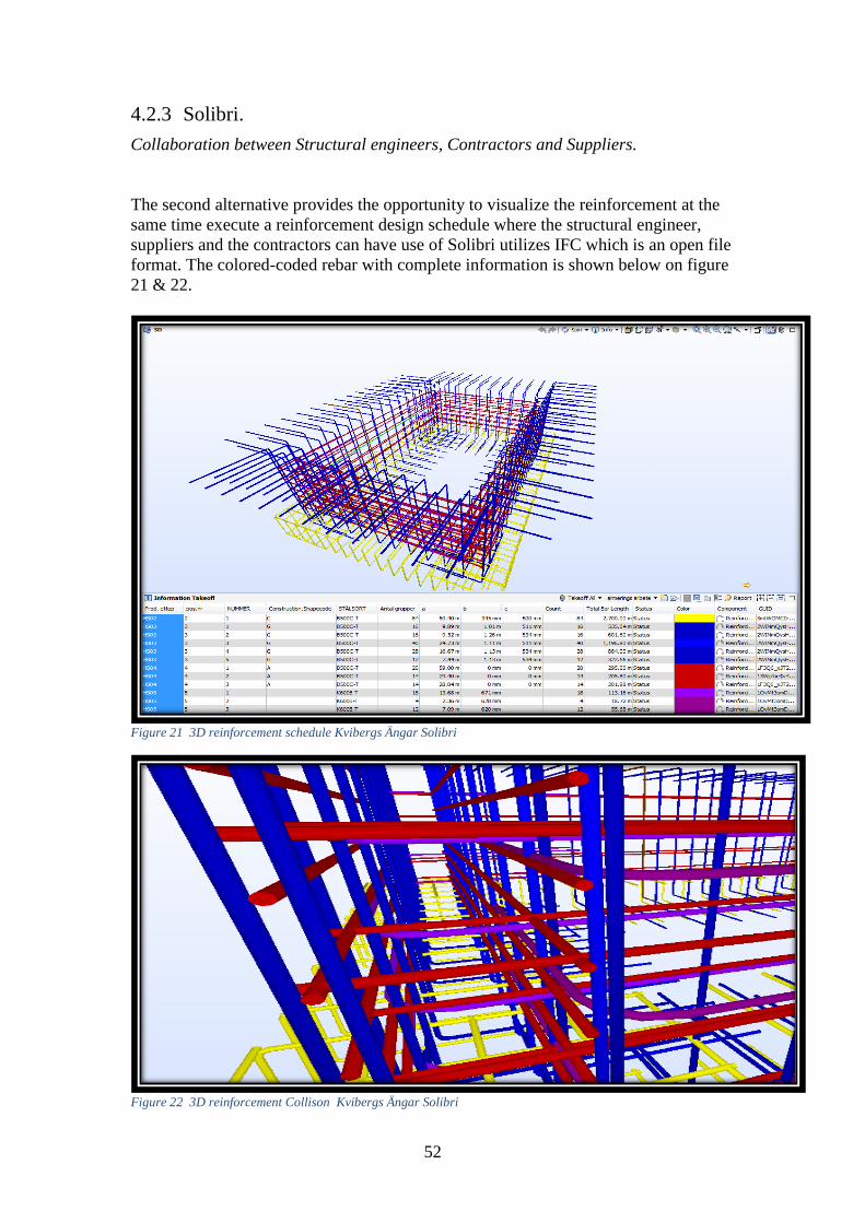
52
4.2.3 Solibri.
Collaboration between Structural engineers, Contractors and Suppliers.
The second alternative provides the opportunity to visualize the reinforcement at the
same time execute a reinforcement design schedule where the structural engineer,
suppliers and the contractors can have use of Solibri utilizes IFC which is an open file
format. The colored-coded rebar with complete information is shown below on figure
21 & 22.
Figure 21 3D reinforcement schedule Kvibergs Ängar Solibri
Figure 22 3D reinforcement Collison Kvibergs Ängar Solibri
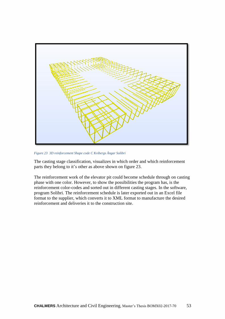
CHALMERS Architecture and Civil Engineering, Master’s Thesis BOMX02-2017-70 53
Figure 23 3D reinforcement Shape code C Kvibergs Ängar Solibri
The casting stage classification, visualizes in which order and which reinforcement
parts they belong to it’s other as above shown on figure 23.
The reinforcement work of the elevator pit could become schedule through on casting
phase with one color. However, to show the possibilities the program has, is the
reinforcement color-codes and sorted out in different casting stages. In the software,
program Solibri. The reinforcement schedule is later exported out in an Excel file
format to the supplier, which converts it to XML format to manufacture the desired
reinforcement and deliveries it to the construction site.
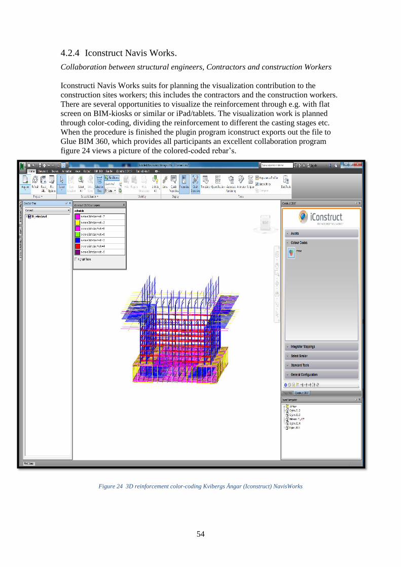
54
4.2.4 Iconstruct Navis Works.
Collaboration between structural engineers, Contractors and construction Workers
Iconstructi Navis Works suits for planning the visualization contribution to the
construction sites workers; this includes the contractors and the construction workers.
There are several opportunities to visualize the reinforcement through e.g. with flat
screen on BIM-kiosks or similar or iPad/tablets. The visualization work is planned
through color-coding, dividing the reinforcement to different the casting stages etc.
When the procedure is finished the plugin program iconstruct exports out the file to
Glue BIM 360, which provides all participants an excellent collaboration program
figure 24 views a picture of the colored-coded rebar’s.
Figure 24 3D reinforcement color-coding Kvibergs Ängar (Iconstruct) NavisWorks

CHALMERS Architecture and Civil Engineering, Master’s Thesis BOMX02-2017-70 55
Through color-coding the casting stage in the parameters A, B type of iron
reinforcement, will this work set facilitate the work preparation for the construction
workers, see more on figure 25 & 26.
Figure 25 3D reinforcement color coding Shape code : B Kvibergs Ängar (Iconstruct) NavisWorks
Figure 26 3D reinforcement color coding Shape code : A Kvibergs Ängar (Iconstruct) NavisWorks

56
4.2.5 BIM 360 Glue.
Collaboration between structural engineers, contractors and construction Workers
Later on is the 3D-reinforcement design visualized on the construction site, through
the software plugin program for Revit; Glue BIM 360. This software program allows
the construction workers to view and have direct connection with the structural
engineers, through the edit, comment option that can be seen on the figures bellow 27
& 28.
Figure 27 3D-reinforcement visualized in Glue BIM 360
Figure 28 Edit reinforcement Glue BIM 360
CHALMERS Architecture and Civil Engineering, Master’s Thesis BOMX02-2017-70 57
5 Discussion & Conclusions
5.1 Communication and interoperability
Between different actors within the construction process
This section is subdivided into discussion related to the different actors within the
construction process.
5.1.1 Structural engineer
The structural engineers mention that more standardized work set with the
reinforcement would contribute to improved communication between the actors
within the reinforcement process. Another factor that would improve the
communication and prevent extra work would be an earlier cooperation between the
structural engineer and the production staff.
“If a picture is worth a thousand words, a 3D-model of a rebar is worth a million!”
The structural engineers say that the advantages, which comes with 3D-model of the
reinforcement, is that it gives the project participants a possibility to get a better
project overview. In addition, a chance to visualize all the strange cuts, easily
obtaining c/c distances, creates awareness of the number of reinforcing iron that
should be in position with right chap length and radius booking. The process is good
but not perfect yet, to reach a perfect one, requires that 3D-reinforcement are utilized
more on projects then current traditional 2D-drawings. A software comparison that
the structural engineers mention is that the software program Revit is more for
designing construction of houses while the other program Tekla from a General
structural engineer’s point of view is more suited for designing steel building
products. In addition, that project conditions are the most decisive of how long the
designing takes with 3D reinforcement work design. The design process goes faster
and easier with 3D-reinforcement then traditional 2D and another benefit with 3D
reinforcement is that it provides the construction workers, productions staff with a
quick update of the reinforcement work.
Skanska Norway have had a great experience of utilizing 3D-reinforcement on
construction projects. The greatest benefits they have experienced has been that the
communication between all project participants has become much better. Which in its
turn has saved their projects time and money.
58
5.1.2 Contractors
The purchasing contractors desire better communication with the structural engineers
so the reinforcement work designs becomes production fitted models/drawings. In
addition, the contractors desire better collaboration between the designers and the
suppliers. Some advantages the contractor mentions is that, 3d-modelled reinforcement
provides better visual information of the reinforcements clashes etc. another advantage
that is appreciated is the tablet/IPad that the site workers can bring with themselves.
Also having the possibility to have direct contact with the structural engineers through
the iPad BIM (BIM 360 glue).
Although the knowledge with working with 3D- visualized reinforcement is small, the
demands of working with them are higher for the contractor on the construction site.
The contractors mention that it gives them a much earlier opportunity to quality check
the reinforcement then before. It is also a time and cost saving method, which is limited
by software complications and unexperienced production staff.On the other hand, they
believe by using the technology more and more on the construction site the contractor
tells us that it will become more improved. In the current situation, they use it to plan
the work on site with the construction worker.
5.1.3 Suppliers
Something, which is desired by the suppliers is the opportunity to improve their digital
communication with their customers, so unnecessary phone calls are avoided.
Receiving the reinforcement schedules through software programs as QR-
reinforcement or DWG: files instead of ordinary PDF:s files formats. The suppliers
wants also to develop their coordination system with their customers so the digital call
offs, planning and the cost is estimated more precisely. In addition, a common digital
database between the participating participants where they can share and become aware
of the projects time, logistic and cost development is preferred.
The suppliers believe that through having long-term agreement with their contractors
and costumers they will develop together a more suitable technical system. This system
will simplify the reinforcement process and develop more standardized approach. This
approach would insure the quality of the reinforcement and deliver the best possible
product.
5.1.4 Construction workers
The construction workers on site mention that they do not mind working and
visualizing the 3D-reinforcement on site, but that it requires an earlier involvement.
Due to reinforcement process, unique characters in projects the construction workers
would appreciate visualizing the project in advance, so the participating people can
come up with cost effective advices and solutions. The workers appreciate having the
opportunity to receive information through their iPads, but point out that there is a
need for some technical and graphical improvement. In addition, enough education
can facilitate the challenges with the technical devices on site. Something that all the
construction workers appreciate is that the 3D-visualization simplifies language
barrier between them and foreign construction workers and having the structural
engineer with them on the construction site. Another mentioned aspect is that more
industrialized reinforcement method creates better work environment, reduces the
waste, they also mention that reinforcement methods usually based on available
resources of staff.

CHALMERS Architecture and Civil Engineering, Master’s Thesis BOMX02-2017-70 59
5.1.5 New roles
Some disappear and some old roles will be strengthen within the
reinforcement processes
As technology progresses, and as it advances, the advancement creates new structures
and systems, which simplifies the current process development. These new structures
lead to more responsibility being added on those involved in these new structures so
the process works as smoothly as possible. The current manual waste of information
flow become minimized as much as possible through utilization of new IT-tools. The
reinforcement process will take part of this information technical development, which
in the future will steer it to new working methods. The new structures provide the
structural engineer with more responsibility then previous, through being capable of
delivering reinforcement schedules. This means at the same time that the current
consultant function of making reinforcement schedules disappears. The current
reinforcement schedule consultants contribute with enormous knowledge concerning
production adaption of the schedules, quality insurance so on. This means that other
remaining actors must take more responsibility concerning production adaptions and
quality insurance. Further on the structural engineer, who designs the reinforcement
schedules must charge for payment for the service they provides. The payment
agreement for the reinforcement schedules should be clarified in the procurement
contract. The agreement should lead to more motivated structural engineers who
shorten the lead-time and deliver higher quality. This means also that the contractor
must get involved earlier in the process and assist with the production adaptations,
casting stages and reinforcement methods. Further below figures show
how the current reinforcement process looks and at the same time how the future
process will look
5.1.6 Preferred Contract form.
The contract form, which facilitates the digital reinforcement process, is Design Build
contract form. The contract form improves the involved actors’ better communication
within the process and provides them better-required early collaboration, which
improves the process. Compared with Design Bid Build contract there information
gap arises. This occurs mostly because the structural engineers often moves on to
other projects when their design process are finished and the supplier are often
procured later in the project. Another contract form that needs to be examined is
Partnering contract form, its advantages also its disadvantages and how it effects the
process. See further below in the appendix Contract Form Of Kungälvs Sjukhus.
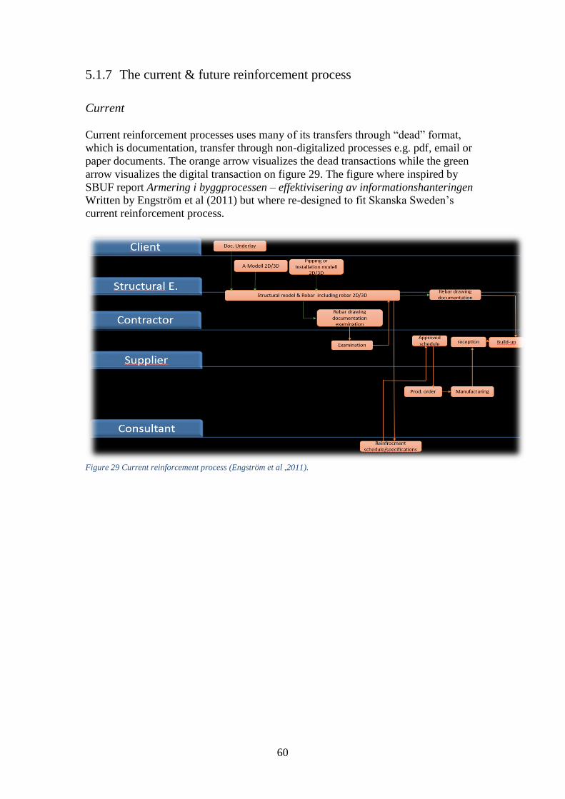
60
5.1.7 The current & future reinforcement process
Current
Current reinforcement processes uses many of its transfers through “dead” format,
which is documentation, transfer through non-digitalized processes e.g. pdf, email or
paper documents. The orange arrow visualizes the dead transactions while the green
arrow visualizes the digital transaction on figure 29. The figure where inspired by
SBUF report Armering i byggprocessen – effektivisering av informationshanteringen
Written by Engström et al (2011) but where re-designed to fit Skanska Sweden’s
current reinforcement process.
Figure 29 Current reinforcement process (Engström et al ,2011).
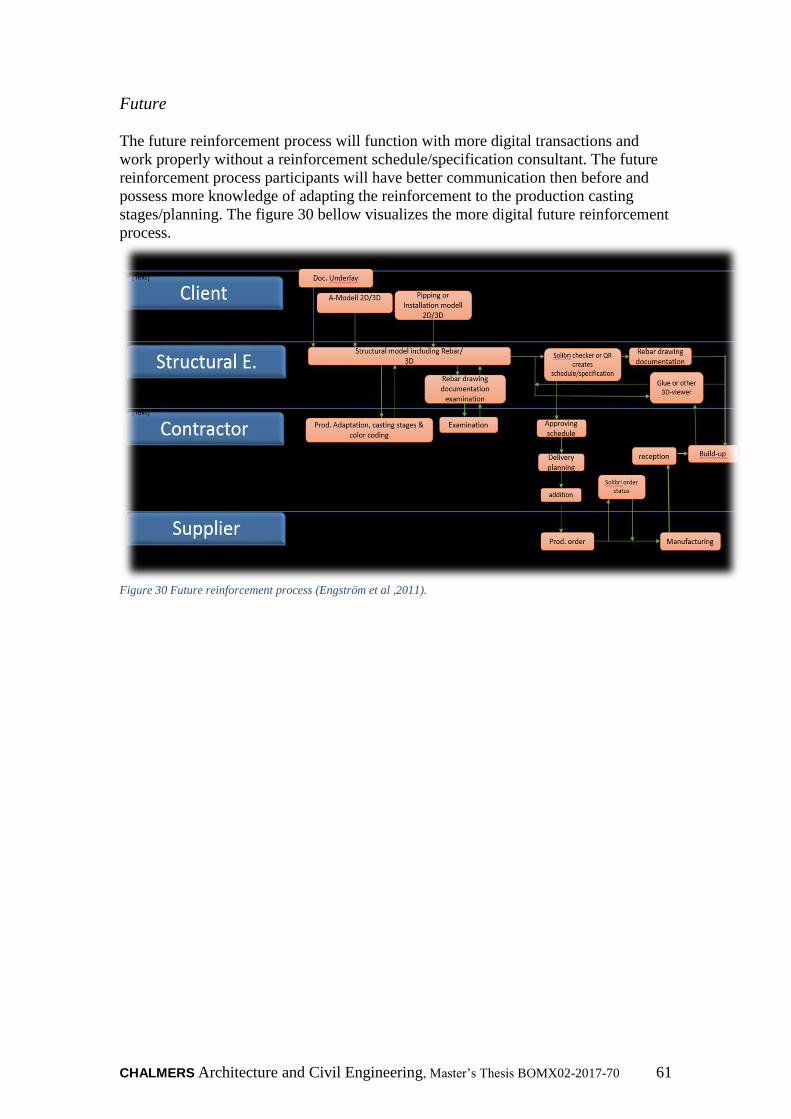
CHALMERS Architecture and Civil Engineering, Master’s Thesis BOMX02-2017-70 61
Future
The future reinforcement process will function with more digital transactions and
work properly without a reinforcement schedule/specification consultant. The future
reinforcement process participants will have better communication then before and
possess more knowledge of adapting the reinforcement to the production casting
stages/planning. The figure 30 bellow visualizes the more digital future reinforcement
process.
Figure 30 Future reinforcement process (Engström et al ,2011).

62
5.1.8 Realization through BIM-use reinforcement
Communication between the various BIM-based IT-tools are just as important as all
other types of communication. That’s why the word interoperability is such an
important factor that facilitates the communication between people and varying types
of software in the construction (AEC) industry. The goal with software
interoperability is creating freely fluent information between different databases or
information models based on one overall perception.
The previous problems with the interoperability have been for example that a file
format had missing information when they were exported out between different
software programs. This in turn has led to designers having to remake the
reinforcement design so it became useful again. The aforementioned issues have
emerged in terms of IFC export/import between the software programs Revit and
Tekla, this happens mostly because Revit and Tekla are two competing software
program companies.
To get around the problem, some different methods have been used. The first method
is through directly creating the schedule in Q-reinforcement/QR (quality
reinforcement) program. The second method, which has been the most effective, has
been utilizing the IFC-export and exporting out the reinforcement design to Solibri,
where the designer can visualize it and create Excel file formats, which later become
converted to XML file formats. The XML file format that can later be used in the
reinforcement schedule-manufacturing program Q-reinforcement or QR to
manufacture the reinforcement. The reason the second method is most effective is
that it allows the structural engineer, contractor and supplier to have an opportunity to
visualize and color-code reinforcement. The second method simplifies both their IT-
tools interoperability and their communication between the different actors involved
in the reinforcement process.
The interoperability continues further on to the construction site where the IT-tool
Glue BIM 360 provides the site workers the opportunity to communicate if something
needs to be edited. The site workers can simply communicate through commenting
edit on their tablets/IPads and upload it into the common shared glue BIM 360 cloud
service.
Furthermore, need for improvement has been demonstrated by the software program
users. These improvements can be achieved through using these software programs
more and more on projects. The benefit with 3D-reinforcement are mainly in larger
projects, because it facilities the visual understanding of complicated projects which
handles large amount of reinforcement, Furthermore are they some great potentials for
smaller ones there the usefulness of the 3D-reinforcment can be tried out. Finally will
this lead to more appreciated improved communication between the actors involved in
the reinforcement process.

CHALMERS Architecture and Civil Engineering, Master’s Thesis BOMX02-2017-70 63
5.2 Conclusion
One reason for the construction industry’s poor productivity is that it still relies on
paper to manage its processes and deliverables such as traditional design drawings.
The purpose of the master thesis has been to evaluate the optimal way of handling the
entire reinforcement chain; from the drawing board to the construction site, where the
actual building is built. Also to figure out the best and the productive working way to
implement 3D-reinforcement in Skanska Gothenburg Sweden. The approach has been
performing interviews on involved participants such as structural engineers,
contractors, suppliers and construction workers. Even test modeling in a case study
project, Kvibergs Ängar. The results of the master thesis has shown that Skanska
Gothenburg Sweden has a functioning process for utilizing digitalized reinforcement,
but that there still is room for improvements in terms of interoperability between
participating project participants and their IT-software tools. The primary
recommendations is to involve all the participants early and obtaining the process as
simply and clearly as possible. The importance of having closer collaboration between
the contractors and the structural engineers has clearly been stated in this master
thesis. Even more important have been pointing out the benefits with having better
collaboration within their own company Skanska through utilizing their own
knowledge they have abroad and other regions in the country. Designing with 3D
reinforcement results in longer design time but reduces the time of the entire
reinforcement process. Further are there some suggestion of improving the IT-
software coordination through utilizing IFC, which is an open file format. IFC allows
the construction process participants to share data regardless of what software
application they use. The thesis has shown through the interview results that working
with digitalized reinforcement contributes to better collaboration in every line of the
reinforcement process and saves time and money. The 3D-modeling chapter has
proven that the possibilities with modeling and visualizing 3D-reinforcement are
currently possible and good. The master thesis indicates that Skanska Gothenburg
Sweden can safely address the digital challenge of working paperless.
64
6 Suggestions for further research
It is time for a new mind-set for the construction industry. Project owners often
believe that their responsibility ends when they award contracts, forgetting that they
pay the economic costs of delay. This master thesis has contributed to identifying
some key improvements areas within the reinforcement process. The thesis has also
proposed some suggestions on how to perform these improvements. Developing
effective interoperability between the participating participants involved in the
reinforcement process and their IT-tools is the biggest challenge with developing the
process. This in its turn makes further research fundamental in order to create an
understanding of how information can become transported between people and
various IT-software in an effective way. The subject proposed has not been within the
scope and purpose of this study and is therefore suggested as subjects for further
research. The following bellow subjects are those, which require further investigation
for example:
How integrated 5D-BIM reinforcement will affect the construction projects
processes, e.g. project delivery, quality and productivity?
How organizational culture and projects procurement forms affects the ability
to implement new ways of working?
How much further on can organizations develop their interoperability
concerning BIM-uses and how could they become sharper?
How much does Virtual-Reality and HoloLens effect the projects productivity
from the procurements board to the construction site?
CHALMERS Architecture and Civil Engineering, Master’s Thesis BOMX02-2017-70 65
7 References
Aretoulis, G. N., Kalfakakou, G. P., & Striagka, F. Z. (2010). Construction material
supplier selection under multiple criteria. Operational Research, 10(2), 209-230.
doi:http://dx.doi.org.proxy.lib.chalmers.se/10.1007/s12351-009-0065-3
Apricon (2014). Apricon C3 i byggprocessen.
http://apricon.se/sv/apricon-c3/om-apricon-c3.aspx [2017-02-02]
Autodesk (2015). http://www.autodesk.se (2015-02-20).
Berg, B. (2009). Qualitative research methods: For social sciences. Boston: Pearson
Education
BIM Alliance. (2014). Vad är BIM?
http://www.bimalliance.se/om_bim_alliance/vad_ar_bim (20 APRIL 2017).
BIM Alliance (2016). BIM - påverkan på affär och avtal.
http://www.bimalliance.se/library/2886/bim_paverkan_pa_affar_och_avtal_foerstudie
rapport_rev_a_7_april_2016.pdf (25 APRIL 2017)
Byggindustrin (2011). BIM – från intresse till planering [Online] Byggindustrin.
http://www.byggindustrin.com/bim---fran-intresse-till-implementering__8807
(1 APRIL 2017).
Building SMART (2011). Model – Industry Foundation Classes.:
http://buildingsmart.com/standards/ifc/model-industry-foundation-
classesifc/?searchterm=IFC (5 APRIL 2017).
Bråthen, K., Moum, A., (2016). Bridging the gap: bringing BIM to construction
workers. Engineering, Construction and Architectural Management, Vol. 23 Issue: 6,
pp.751-764
Deutsch, R., Books24x7 (e-book collection), Ebook Central (e-book collection) &
Books24x7, I. 2011, BIM and integrated design: strategies for architectural practice,
1st;1; edn, Wiley, Hoboken, N.J.
Eastman, C., Teicholz, P., Sacks, R., & Liston, K. (2008). BIM Handbook: A Guide
to Building Information Modelling for Owners, Managers, Designers, Engineers, and
Contractors. Hoboken, New Jersey: John Wiley & Sonic, Inc., pp. xi-xii, 13, pp. 18-
19.
Engström, D., Hyll, H., Fredsdotter, J. & Larsson, R. (2011). Armering i
byggprocessen – effektivisering av informationshanteringen. Göteborg, NCC.
Celsa Steel Sercice (2012). ILF. Celsa Steel. http://celsa-steelservice.se/produkter/ilf/:
(11 APRIL 2017).
66
Cho, Y.S., Lee, S.I. & Bae, J.S. (2014). "Reinforcement Placement in a Concrete Slab
Object Using Structural Building Information Modeling", Computer‐Aided Civil and
Infrastructure Engineering, vol. 29, no. 1, pp. 47-59.
Government Construction Client Group From the BIM Industry Working Group,
(2011). A report for the Government Construction Client Group Building Information
Modelling (BIM) Working Party Strategy Paper. London: Department of Business,
Innovation and Skills.
Granroth, M. (2011). BIM – Byggnads Informations Modellering. Stockholm:
Godoymedia.
Green, E. (2016). The Role of Interoperability in BIM. Engineering.com.
http://www.engineering.com/BIM/ArticleID/12131/The-Role-of-Interoperability-in-
BIM.aspx. (15 APRIL 2017)
Harryson, P. (2002). Industrial bridge construction: merging developments of
process, productivity and products with technical solutions, Avdelningen för
konstruktionsteknik, Publikation 02:1, Göteborg: Chalmers Tekniska Högskola, 41.
Hertzell, T. Bergenudd, C. (2003). BYGGHANDLINGAR 90–byggsektorns
Rekommendationer för redovisning av byggprojekt; part 2.Stockholm: SIS Förlag
AB: (SIS Förlag AB. ISBN 91 7162 826-8)
Haymaker J. and Fischer M. (2001). Challenges and benefits of 4D modelling on the
Walt Disney Concert Hall Project, Working Paper No. 64, Center for Integrated
Facilities Engineering, Stanford University, CA.
(Available at www.stanford.edu/group/CIFE/Publications.)
Kam C., Fischer M., Hänninen R., Karjalainen A., and Laitinen J. (2003). The
Product Model and Fourth Dimension Project, Journal of Information Technology in
Construction, Vol. 8, pp. 137-166. (Available at
www.itcon.org.)
Kensek, K.M., Noble, D. & Ebook Central (e-book collection) (2014). Building
information modeling: BIM in current and future practice, 1st edn, Hoboken, New
Jersey : Wiley.
Kraider,R., Messner, J., & Dubler, C. (2010). Detmining the Frequency and Impact of
Applying BIM for Different Purposes on Building Projects, in Procedings of the 6th
International Conference on Innovation in Architecture, Engineering and
Construction (AEC) .Pennsylvania: Penn State University
Lutz, J. & Gabrielsson, E. (2002). Bygkommissionen [Online]:
http://www.bygg.org/files/pdf/17.%20byggsektorns_struktur_och_utvecklingsbehov.
(1 Feb 2017).

CHALMERS Architecture and Civil Engineering, Master’s Thesis BOMX02-2017-70 67
Löfgren, I. (2002). In-situ concrete building systems: Developments for industrial
Constructions. Avdelningen för konstruktionsteknik Publikation 02:2, Göteborg,
Chalmers Tekniska Högskola.,
McKinney, K., Kim, J., Fischer,M., Howard ,C,. " Interactive 4D-CAD by Stanford
University. (29 APRIL 2017)
Merriam, Sharan B (1994). Fallstudien som forskningsmetod. Lund: Studentlitteratur
Mistry,H. (2016). 4 Steps of Getting BIM Ready: What do you need to know:
http://www.ikopolymeric.com/4-steps-of-getting-bim-ready/ (April 29, 2017)
Mittbygge (2011). Mittbygge [www]. Downloaded from http://www.mittbygge.se.
(April 26, 2017)
Nordstrand, U. (2000). Byggprocessen. Stockholm: Liber
Sandberg, J., Hjort, B. (1998). Rationell armering: Ekonomi, ergonomi, miljö.
Halmstad: Tryckmedia, 144 pp.
Silverman, D. (2010). Doing Qualitative Research. 3rd edn. London: SAGE
Publications.
Skanska AB. (2017a). Om Skanska. One Skanska. (http://www.skanska.se/om-
skanska/skanska-i-sverige/building-information-modeling-bim ). (2 April 2017)
Skanska AB. (2017b). Vårt Sätt att arbeta (Vsaa), Processkarta Projektering Hus. One
Skanska. (https://vsaa.skanska.se/teknik/projekteringsuppdrag/verksamhetsspecifika-
arbetssätt/processkarta-projektering-hus). (2 April 2017)
Staub-French S. and Fischer M. (2001). Industrial Case Study of Electronic Design,
Cost, and Schedule Integration. Technical Report No. 122, Center for Integrated
Facilities Engineering, Stanford University, CA. (Available at
www.stanford.edu/group/CIFE/Publications)
Tekla (2012a). Så började det. www.tekla.com.
http://www.tekla.com/SE/ABOUT-US/HISTORY/Pages/Default.aspx (2012-03-14)
Vasshaug, H. (2014). The Dark Arts of Revit: Concrete
Reinforcement Modeling and Construction. Revit Technology Confirence. 29-31
MAY 2014, Melbourne. p. 2-88
Wallén, G. (1996). Vetenskapsteori och forskningsmetoder. Lund: Studentlitteratur.

68
8 Appendices
Content
The Swedish design requirement
Contractual form of the project: Kungälvs Sjukhus
Contractual form of the project: Kungälvs Sjukhus
Traditional Reinforcement Schedule
Specification sheet 2A

CHALMERS Architecture and Civil Engineering, Master’s Thesis BOMX02-2017-70 69
8.1 The Swedish design requirement
Currently is 3D modelling in the Swedish construction design requirements only seen
as a helping aid tool while 2D designing is more included in the design regulations of
AB04 while 3D- design modelling are not stamped as construction documents, but
requires an constant flow of communication between the entrepreneur and designer so
the 3D-modell stays updated (BIM Alliance, 2016).
The construction documents “Bygghandlingar 90” (BH90) are the fundamental
documents, which are the underlying basis for the production site of the construction
industry. BH90 documents contains two chapters, which presents how the
reinforcement should be designed, these chapters are two and four. While chapter 8
describes how digital supplies for the construction and management is delivered, it
replaces the earlier edition accounting CAD. BH90 contains also other basic
requirements for designing construction documents (Hertzell T. Bergenudd, C. 2003).
The design recommendation that BH90 recommends are that the designer should stick
to the three different line combinations which called, symbol line, material lines and
helplines. Mostly because in drawings, do they the lines illustrates different kind of
meanings, with their various kind of characters and dimensions. Especially texts and
numerus digits, which has standardized fonts with the standard high of 2.5mm.
(Hertzell T. Bergenudd, C. 2003). Some illustrations of 2D plan and sectional views
is presented on figure below.
As seen above, is a brief presentation of the reinforcing rebar on a concrete beam. The
presentation illustrates the end markers for each solid reinforcement is designed
downwards while the vertical lines end marks is designed to the right. While it is the
other way around for dashed lines i.e. up and to the left.

70
While in the sectional- and details, rebar is shown as bellow
Following further down is distribution line presented which shows the reader that has
the similar rebar’s along, the on the structural plan view.

CHALMERS Architecture and Civil Engineering, Master’s Thesis BOMX02-2017-70 71
Design Categories
The rebar information and properties is written along its reference line. The rebar data
is called design categories and is presented according to the following six criteria’s
which are the amount of bars/stacks of rebar, dimension, quality, the centre distance
between bars, bending type and also the rebar number’s that references reinforcement
list.
The design categorization of the rebar bellow indicates that it has bending type B, the
unique rebar number 201, at the same time is it viewed that its twenty stocks rebar’s
with the diameter of twelve millimetres. The Steel quality of the rebar is B500BT and
are laid with a distance of 110mm.
The rebar’s mesh are designed with outer contour, which are in scale and follows the
attached other reinforcing elements. The reinforcement mesh has diagonal lines,
which are from the upper right to the lower left side of the corners. The rebar mesh is
also names after its position depending if it’s positioned on the top or on the lower
edge of the structural concrete. The rebar’s on the top position is named in Swedish
terms (ÖK) while those on the lower edge is named (UK). Continuously according to
BH90 should the designer primarily use the paper size 594x841 mm size when the
original design is printed out, the Swedish term for the paper size is called A1 and
belongs to A-series paper format (Hertzell, T. Bergenudd, and C. 2003).
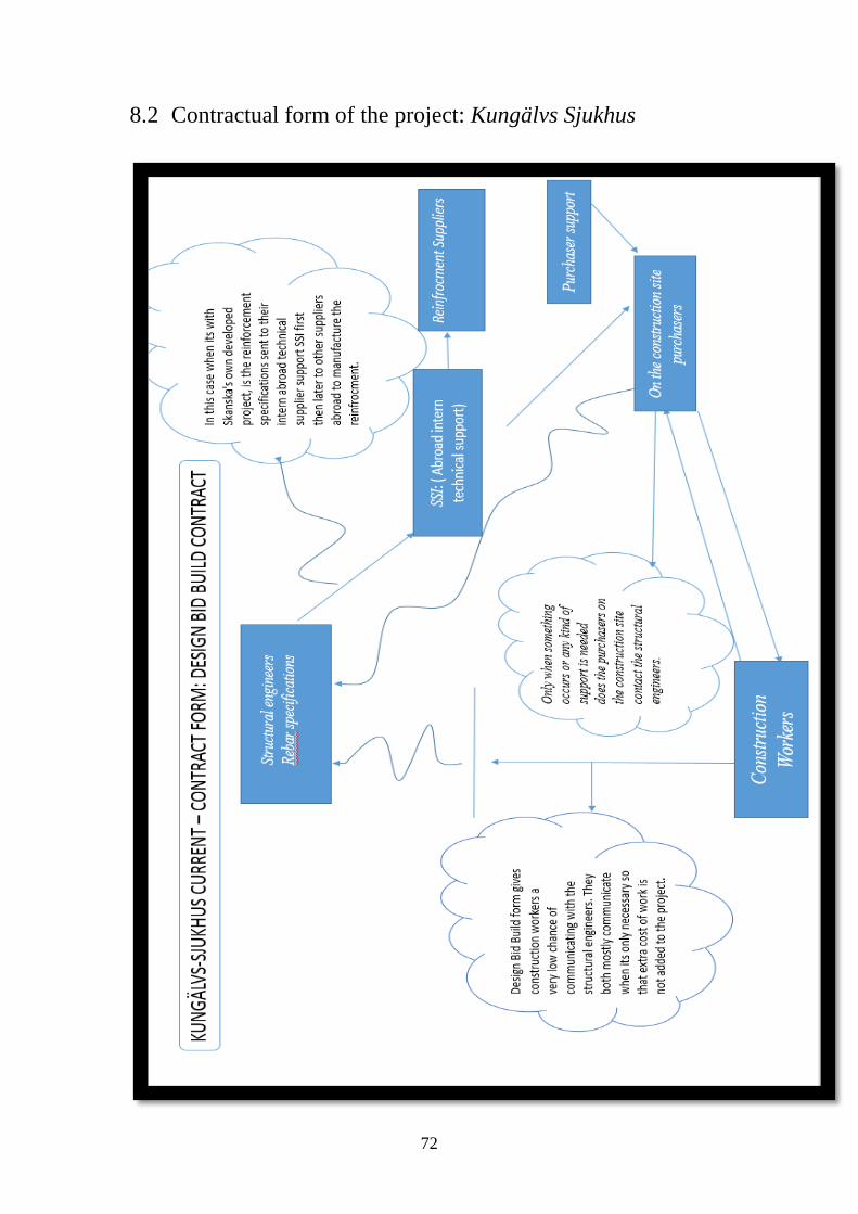
72
8.2 Contractual form of the project: Kungälvs Sjukhus
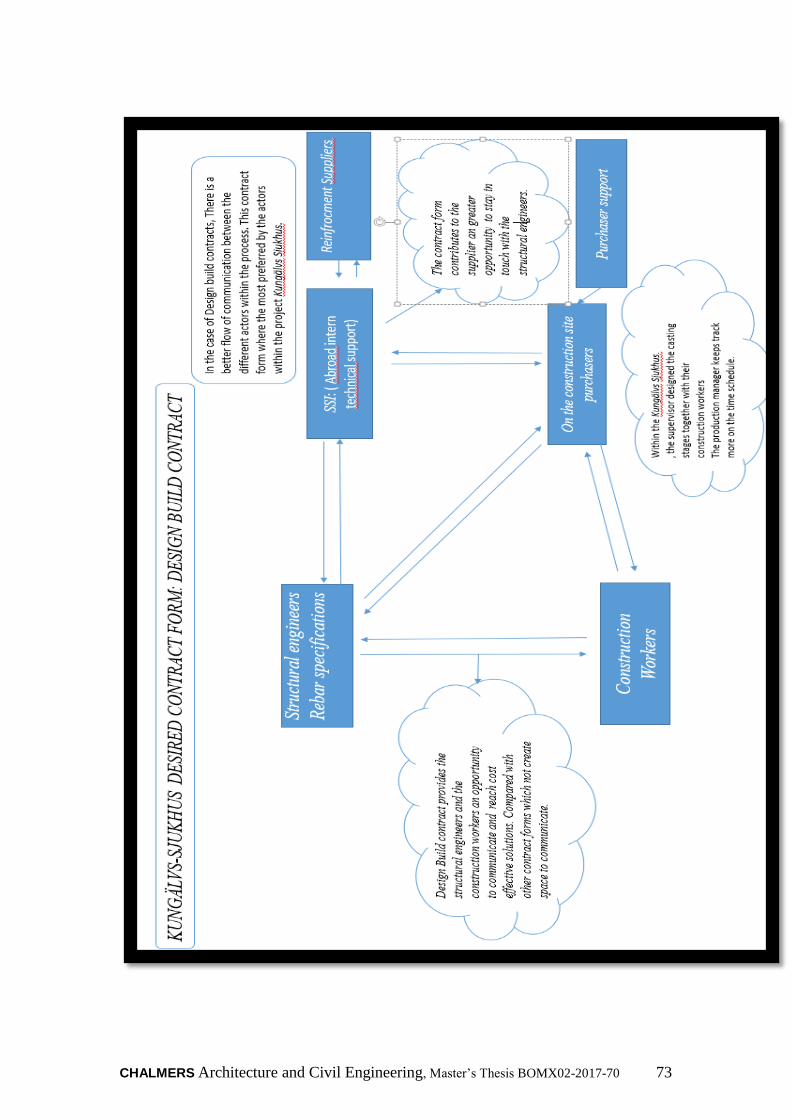
CHALMERS Architecture and Civil Engineering, Master’s Thesis BOMX02-2017-70 73
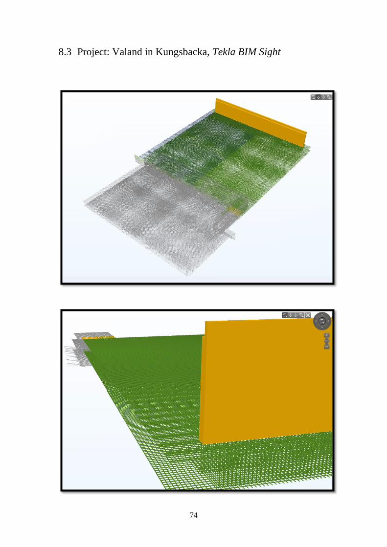
74
8.3 Project: Valand in Kungsbacka, Tekla BIM Sight
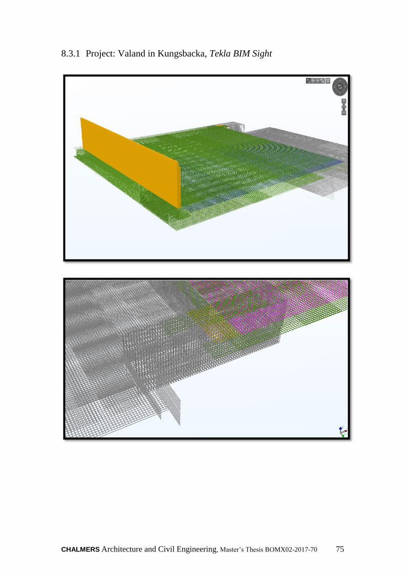
CHALMERS Architecture and Civil Engineering, Master’s Thesis BOMX02-2017-70 75
8.3.1 Project: Valand in Kungsbacka, Tekla BIM Sight
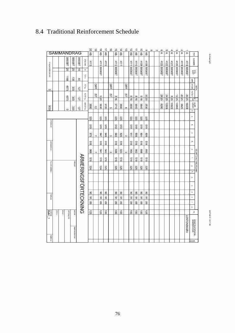
76
8.4 Traditional Reinforcement Schedule
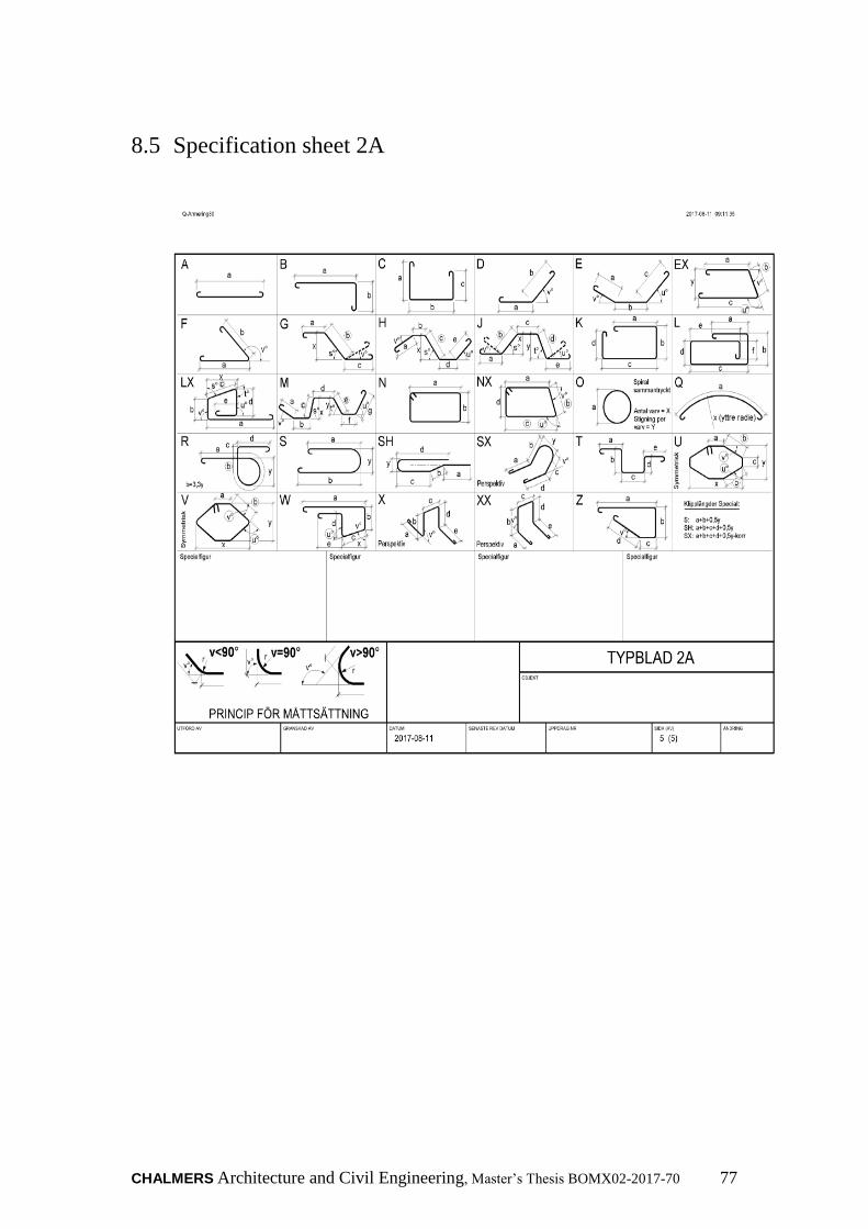
CHALMERS Architecture and Civil Engineering, Master’s Thesis BOMX02-2017-70 77
8.5 Specification sheet 2A