Embed Size (px)
Citation preview

Master’s Thesis
Generating Web Applications
with Abstract Pageflow Models
carried out at the
Information Systems InstituteDistributed Systems Group
Vienna University of Technology
under the guidance ofo.Univ.Prof. Dr. Dustdar Schahram
andUniv.Ass. Dipl.Ing. Vasko Martin
as the contributing advisor responsible
by
Ernst OberortnerPoststrasse 4
9551 BodensdorfMatr.Nr. 0027144
Bodensdorf, 03. May 2007

i
Acknowledgements
First and mostly important I thank my parents, Christine and Ernst, whoalways supported me during my whole studies.
Furthermore I want to thank my advisors Schahram Dustdar and MartinVasko for their help, guidance and standby during the realization of thiswork.
Finally I thank all my colleagues and friends that I met during my uni-versity life for their great teamwork and collaboration in order to graduatestudies.
ii
Abstract
Due to the fact of platform-independence and worldwide accessibility, thepopularity of the Web leads to countless Web applications. In the courseof this work, a possibility for an automated generation of Web applicationsbased on a MDA (Model-Driven Architecture) is introduced.
This work is concentrated on the definition of a meta-model for modeling Webapplications based on the principles of the MVC (Model-View-Controller)pattern. The main task is the automated generation of modeled Web ap-plications. Models of Web applications contain information about graphicaluser interfaces on Web pages and the pageflow within the Web application.Hence the defined meta-model specifies the syntax and structure of Models.Furthermore the meta-model serves for validating models.
The primary aim is the automated generation of the layout and structureof Web pages, hence the View of the MVC pattern. Furthermore an XMLfile is generated that serves as input for the Controller that controls thepageflow. For the time being the developer is responsible for the Model ofthe MVC pattern. Therefore a methodology for dealing with generated andmanually written code is developed in order that the manually written codedoes not become overwritten in a subsequent generator run.
To prove our approach of generating Web applications based on a MDA,a prototype is introduced. This prototype is a JSF (JavaServer Faces) Webapplication for the Apache Tomcat Web server.

iii
Zusammenfassung
Die Beliebtheit von Web Applikationen ist aus Gründen der Plattformunab-hängigkeit und des weltweiten Zugriffs stark gestiegen. Aus diesem Grundbeschäfigt sich diese Arbeit mit der automatischen Generierung von WebApplikationen basierend auf einer MDA (Model-Driven Architecture).
Insbesondere konzentriert sich diese Arbeit auf die Definition eines Meta-Modells für die Modellierung von Web Applikationen welche auf dem MVC(Model-View-Controller) Pattern aufbauen. Die Hauptaufgabe besteht in derautomatischen Generierung der modellierten Web Applikationen. Die Mod-elle der Web Applikationen beinhalten Informationen über die Webseitenund den Page-Flow innerhalb der zu generierenden Web Applikation. Da-her wurde ein Meta-Modell entwickelt welches die Syntax und die Struktursolcher Modelle beschreibt. Weiters dient das Meta-Modell zur Validierungder Modelle.
Das Hauptaugenmerk liegt in der Generierung der grafischen Oberflächenvon Webseiten, also im View des MVC Patterns. Der Controller steuert denPage-Flow. Eine XML Datei wird vom Generator erzeugt welche die Infor-mationen über den Page-Flow beinhaltet und als Input für den Controllerdient. Zurzeit ist der Programmierer für die Programmierung des Modells desMVC Patterns zuständig. Aus diesem Grund muss bei der Codegenerierungzwischen generiertem und dem vom Programmierer geschriebenen Code un-terschieden werden um ein Überschreiben des handgeschriebenen Codes beieiner erneuten Codegenerierung zu verhindern.
Um die Arbeitsweise unseres Ansatzes zu demonstrieren haben wir einenPrototyp erstellt. Dieser Prototyp ist eine JSF (JavaServer Faces) Web App-likation welche auf dem Apache Tomcat Web Server ausgeführt werden kann.

iv
Contents
1 Introduction 11.1 Motivation . . . . . . . . . . . . . . . . . . . . . . . . . . . . . 21.2 Problem Definition . . . . . . . . . . . . . . . . . . . . . . . . 31.3 Organization of this thesis . . . . . . . . . . . . . . . . . . . . 4
2 Theory 52.1 The Model-View-Controller (MVC) Pattern . . . . . . . . . . 52.2 The JavaServer Faces (JSF) Framework . . . . . . . . . . . . . 8
2.2.1 JSF Technology . . . . . . . . . . . . . . . . . . . . . . 92.2.2 JSF Web Applications . . . . . . . . . . . . . . . . . . 102.2.3 Guidance for developing JSF Web Applications . . . . 10
2.2.3.1 Mapping the FacesServlet instance . . . . . 112.2.3.2 Creation of JSP Web pages . . . . . . . . . . 112.2.3.3 Defining the Pageflow . . . . . . . . . . . . . 132.2.3.4 Development of the Java Beans . . . . . . . . 142.2.3.5 Adding managed bean declarations . . . . . . 15
2.2.4 Benefits of JSF Web applications . . . . . . . . . . . . 162.3 Model Driven Architecture (MDA) . . . . . . . . . . . . . . . 17
2.3.1 Terminology . . . . . . . . . . . . . . . . . . . . . . . . 172.3.1.1 Model . . . . . . . . . . . . . . . . . . . . . . 172.3.1.2 Model Driven . . . . . . . . . . . . . . . . . . 172.3.1.3 Architecture . . . . . . . . . . . . . . . . . . . 172.3.1.4 Platform . . . . . . . . . . . . . . . . . . . . . 172.3.1.5 Platform Independent Model (PIM) . . . . . 172.3.1.6 Platform Specific Model (PSM) . . . . . . . . 182.3.1.7 Model Transformations . . . . . . . . . . . . . 182.3.1.8 Domain . . . . . . . . . . . . . . . . . . . . . 192.3.1.9 Meta-model . . . . . . . . . . . . . . . . . . . 192.3.1.10 Abstract Syntax . . . . . . . . . . . . . . . . 192.3.1.11 Static Semantic . . . . . . . . . . . . . . . . . 192.3.1.12 Domain Specific Language (DSL) . . . . . . . 192.3.1.13 Meta Object Facility (MOF) . . . . . . . . . 192.3.1.14 XML Metadata Interchange (XMI) . . . . . . 20
2.3.2 Aims of MDA . . . . . . . . . . . . . . . . . . . . . . . 202.3.3 Metamodeling . . . . . . . . . . . . . . . . . . . . . . . 21
2.4 Eclipse Modeling Framework (EMF) . . . . . . . . . . . . . . 23

v
2.5 openArchitectureWare (oAW) . . . . . . . . . . . . . . . . . . 252.5.1 Workflow Engine . . . . . . . . . . . . . . . . . . . . . 252.5.2 Expression Framework . . . . . . . . . . . . . . . . . . 262.5.3 Xpand2 . . . . . . . . . . . . . . . . . . . . . . . . . . 262.5.4 Xtend . . . . . . . . . . . . . . . . . . . . . . . . . . . 262.5.5 Check . . . . . . . . . . . . . . . . . . . . . . . . . . . 27
2.6 Apache Ant . . . . . . . . . . . . . . . . . . . . . . . . . . . . 282.7 Separation of Generated and Handwritten Code . . . . . . . . 29
2.7.1 Protected Regions . . . . . . . . . . . . . . . . . . . . . 292.7.2 Solutions for Protected Regions . . . . . . . . . . . . . 30
3 Related Work 32
4 Description of our Approach 384.1 The Meta-Model . . . . . . . . . . . . . . . . . . . . . . . . . 38
4.1.1 Modeling of Web pages . . . . . . . . . . . . . . . . . . 394.1.2 Modeling of the Pageflow . . . . . . . . . . . . . . . . . 44
4.2 Code Generation with oAW . . . . . . . . . . . . . . . . . . . 464.2.1 Workflow . . . . . . . . . . . . . . . . . . . . . . . . . 464.2.2 Check - Model Validation . . . . . . . . . . . . . . . . 504.2.3 Xpand2 - Templates . . . . . . . . . . . . . . . . . . . 50
4.3 A Prototype for Visualizing the Mode of Operation . . . . . . 604.3.1 The Generated Prototype Web Application . . . . . . . 64
4.3.1.1 Generated Web Pages . . . . . . . . . . . . . 654.3.1.2 Generated Java Beans . . . . . . . . . . . . . 694.3.1.3 Generated Pageflow Information . . . . . . . 71
5 Evaluation 735.1 Evaluation of the Meta-Model . . . . . . . . . . . . . . . . . . 735.2 Evaluation of the Templates . . . . . . . . . . . . . . . . . . . 745.3 Evaluation of the Prototype . . . . . . . . . . . . . . . . . . . 745.4 Evaluation of Code Separation . . . . . . . . . . . . . . . . . . 75
6 Further Work 766.1 The Meta-Model . . . . . . . . . . . . . . . . . . . . . . . . . 766.2 Model Transformations . . . . . . . . . . . . . . . . . . . . . . 76
7 Summary and Conclusion 77

vi
A Figures 79
B Tables 80
C Listings 81
D Bibliography 82

1
1 Introduction
The main purpose of this project is the development of a Model-Driven Archi-tecture (MDA) ([9]) for an automatic generation of Web applications that arebased on the Model-View-Controller (MVC) ([8]) pattern. To demonstratethe functioning of our approach, JavaServer Faces (JSF) ([6]) are used be-cause they are popular Web applications based on the MVC pattern. For therealization of this project the Eclipse Modeling Framework (EMF) ([15]) incompanion with the openArchitectureWare (oAW) ([18]) plug-in for Eclipse([13]) were used because they provide helpful and strong facilities for model-ing software systems and code generation.
The MVC pattern separates data and their graphical appearance. The page-flow is controlled by the Controller. The Model is responsible for fetchingdata (e.g. by accessing a database) and the View is responsible for the graph-ical appearance of the data within Web pages. The JSF framework providesan implemented Controller that needs an XML file that describes the page-flow as input. JavaServer Pages (JSP) represent the View and EnterpriseJava Beans (EJB) represent the Model.
Our MDA is built-up on models that describe the structure of a Web ap-plication that should be generated. These models contain information aboutgraphical user interfaces on Web pages as well as the pageflow. To define thesyntax of models, the so-called Domain Specific Language (DSL), a meta-model was introduced. The meta-model is also responsible for the validationof models.
The modeling of Web applications can be done in any CASE tool that pro-vides an exportation of the model to the eXtensible Metadata Interchange(XMI) file format. This XMI file is passed to our generator and if the modelis valid, the Web application is generated.
One benefit of applying a MDA is to reduce the time-consuming processof developing Web applications. Furthermore the quality of the generatedcode as well as the maintenance are improved.

1.1 Motivation 2
1.1 Motivation
The popularity of the Web and its advantages as a client-server platform ledto countless Web applications. Web applications are global environments fordelivering all kinds of applications. One reason for the popularity of Webapplications is the facility to access an application from all over the world onany platform. Furthermore the maintenance of Web applications is arrangedin a centralized way at minimal costs [4].
We base the necessity of developing Web applications in a rapid and high-quality way on the following statements:
Web Applications are becoming the first choice for most business applica-tion development [23].
Designing and maintaining Web applications is one of the major challengesfor the software industry [22].
The maintenance of a Web application is getting difficult due to the inherentcomplexity of the system [24].
A MDA improves the quality and speed of developing Web applications aswell as their maintenance. Furthermore a MDA unifies the steps of develop-ment and the integration from business modeling through architectural andapplication modeling [12].
To prove our approach of generating Web applications based on a MDA,the JSF framework is used because it is currently a popular Web orientedMVC implementation. Most Web applications are based on the MVC pat-tern for separating data and their presentation. The JSF framework providesserver side user interface components for Web applications based on the Javatechnology. The main reason for our choice of the JSF framework lies in theready-made Controller that controls the pageflow.

1.2 Problem Definition 3
1.2 Problem Definition
The main purpose of this project lies in an automated generation of Webapplications based on a MDA. A MDA achieves a certain level of abstractionthat leads in an improvement of automation, productivity, quality and main-tenance in the field of developing Web applications. Moreover MDA aimsfor interoperability, portability and standardization of models for popularapplication areas [3].
Web applications are described in models that define the user interfaces ofWeb pages as well as the pageflow. The pageflow describes all kinds of subse-quent Web pages of a certain page. Our approach aims to a process-orienteddefinition of the pageflow to improve the clarity and understanding. Forthe definition of the structure and syntax of models, a meta-model has tobe defined. Hence, the meta-model defines the DSL. Each model is an in-stance of the meta-model. The meta-model is also used for validating models.
Our approach describes a MDA for generating Web applications based onthe MVC pattern. To demonstrate the functioning of our approach we areconcentrated in an automated generation of JSF Web applications that aredeployed especially on the Apache Tomcat Web server. Therefor a prototypeis introduced that is described later in this work. Further works can be doneto generate Web applications that can be deployed not only for a certainWeb server.
Our defined meta-model supports the modeling of Web pages and the page-flow. The Controller is given by the JSF framework that controls the page-flow. Our code generator generates an XML file that serves as input for thisController. This XML is built-on the given model that describes the Webapplication. Presently the developer is responsible for the Model of the MVCpattern, hence for fetching data, e.g. accessing a database. This results inthe problem of handling generated and manually written code.
At present our generator generates the Web pages, a configuration file forthe Tomcat Web server, an XML file that contains the information aboutthe pageflow that serves as input for the JSF Controller, Java Beans to storedata as well as an XML file for Apache Ant that eases the deployment of thegenerated Web application for the Tomcat Web server.

1.3 Organization of this thesis 4
1.3 Organization of this thesis
This section gives an overview of the sections in this report and their contents.
• Section 2 - TheoryThis section describes the main technologies used in this work. Thecharacteristics of the MVC pattern are specified. Furthermore we in-troduce the JSF framework. Then an overview of MDA is given wherethe main part lies in the Metamodeling section. Moreover the EMF aswell as the oAW plug-in for Eclipse are described. The Theory sectionends with an overview of possibilities how generated and handwrittencode can be separated.
• Section 3 - Related WorkThe Related Work section gives an overview about research works formodeling Web applications. We specify the characteristics of otherapproaches introduced by researching teams on other universities orlaboratories.
• Section 4 - Description of our ApproachSection 4 specifies our defined approach how to generate a given mod-eled Web application. First we introduce our defined meta-model. Af-terwards we describe how the Web application is generated with theoAW plug-in for Eclipse. Subsequently we introduce a prototype thatdemonstrates the functioning of our approach. The prototype is a JSFWeb application that can be deployed on the Apache Tomcat Webserver.
• Section 5 - EvaluationThis section serves for an evaluation of our approach. We evaluate ourdefined meta-model, the defined templates for generating the Web ap-plication, the prototype as well as our utilized solution for the problemof handling generated and manually written code.
• Section 6 - Further WorkSection 6 qualifies how our approach can be extended and improved infuture work.
• Section 7 - Summary and ConclusionThe Summary and Conclusion section repeats all important aspects ofthis work and serves as conclusion of our work.

5
2 Theory
2.1 The Model-View-Controller (MVC) Pattern
Web applications present contents in numerous pages containing various datato users. Developer teams are responsible for the design, implementation andmaintenance of such Web applications. Therein rests the problem that mul-tiple types of user interfaces must be supported, e.g. HTML Web pages forusers and Java Web pages for developers. This problem forces that the samedata needs to be accessed in different views. Furthermore an update of thesame data can be done through different user interfaces. Supporting multi-ple types of views and interactions should not impact the components thatprovide the core functionality of the Web application [7].
The MVC pattern is used to put this things right by separating the corebusiness functionality from the presentation and control logic. Such separa-tion allows multiple views of the same data. This eases to implement, testand maintan multiple clients.
Figure 1: Model-View-Controller
Figure 1 demonstrates the division of the MVC pattern into the Model, Viewand Controller components and their relationships. Solid lines indicate directassociations and dashed lines indirect associations [8]. The MVC pattern isdivided into three elements:

2.1 The Model-View-Controller (MVC) Pattern 6
• ModelThe Model encapsulates the functional core of an application. It rep-resents the data and grants access to the data.
• ViewThe View is responsible for the rendering of the data of the Model,typically user interface elements. It specifies exactly how the datashould be presented. The View must update the presentation of thedata if the data in the Model has been changed [8]. Generally, the Viewhas read-only access to the Model because the View should not changethe state of the Model.
• ControllerThe Controller is responsible for calling methods of the Model thatchange the data. The Controller and the View have equal opportunityto access the Model. The Controller does not copy data values from theModel to the View, although it may place values in the Model and tellthe View that the data of the Model has been changed. The Controllermay also select a new View that should be presented to the user, e.g.a Web page of results [8].
In Web applications based on the MVC pattern the View is the actual HTMLdocument and the Controller is responsible for the content within the HTMLcode as well as the control of the pageflow. The Model is represented by theactual content stored in a database or XML-files.
The following scenario shows actions that occur if a user interacts with theView [8]:
1. The user interacts with an user interface
2. The View recognizes that an action has occurred and calls a methodthat is registered to be called when such an action occurs
3. The View calls the appropriate method on the Controller
4. The Controller accesses the Model

2.1 The Model-View-Controller (MVC) Pattern 7
5. The Model notifies all Views that the data has been changed. In Javatechnology-based applications the Controller may also be responsiblefor updating the View.
The benefits of MVC are:
• Substitutable user interfacesDifferent Views and Controllers can be substituted to provide alternateuser interfaces for the same Model.
• Multiple simultaneous views of the same Model
• Synchronized Views
• Easier user interface changes
• Easier testing
On the other hand the drawbacks of MVC are:
• Increased complexity
• Close coupling of View and Controller to the Model:Changes of the data require changes in the View and may require ad-ditional changes in the Controller
• Close coupling between View and ControllerA strict separation between View and Controller is difficult

2.2 The JavaServer Faces (JSF) Framework 8
2.2 The JavaServer Faces (JSF) Framework
The JSF framework is a server-side framework for user interface componentsfor Web applications based on the MVC pattern.
• ModelThe Model is represented by Enterprise Java Beans (EJB).
• ViewThe View is represented by JavaServer Pages (JSP).
• ControllerThe Controller is represented by Java Servlets.
First we’ll take a closer look to EJB and JSP:
• Enterprise Java Beans (EJB)An EJB is a pieces of code that has properties and methods to im-plement modules of the business logic [5]. There are three kinds ofEJB:
– Session BeansA Session Bean represents a transient conversation with the client.They are valid until the client finishes its execution. [5].
– Entity BeansEntity Beans are distributed objects that have a persistent statewhere the persistency may or may not be managed by the bean it-self. Hence, they are divided into Container-Managed Persistence(CMP) and Bean-Managed Persistence (BMP).
• JavaServer Pages (JSP)JSP allow the programmer to put Java code and certain pre-definedactions into HTML documents. A JSP page is a text-based documentthat contains static data and JSP tags that construct dynamic content[5]. The JSP tag libraries act as extensions to the standard HTMLor XML. Tag libraries provide a platform independent extension of aWeb server. Static data can be expressed in any text-based formatssuch as HTML [5]. JSP pages are compiled into Java Servlets by aJSP compiler that generates a Java Servlet in Java code or directly inbyte-code. JSP can be seen as an abstraction of Java Servlets. Sun

2.2 The JavaServer Faces (JSF) Framework 9
recommends that the MVC pattern should be used with the JSP filesin order to split the presentation from request processing and datastorage. Either regular Java Servlets or separate JSP files are used toprocess the request. After the request processing has finished, controlis passed to a JSP page for creating the output.
2.2.1 JSF Technology
Like mentioned above, the JSF framework provides server-side componentsfor Java based Web applications. The framework consists of two main com-ponents [5]:
• An API for representing user interface components and managing theirstate, handling events, server-side validation, defining page navigationand supporting internationalization and accessibility
• Two JSP custom tag libraries for expressing user interface componentswithin a JSP page
Figure 2: JavaServer Faces [5]
Figure 2 shows the organization of JSF Web applications. The client (Browser)requests the JSP page myform.jsp that contains JSF tags. The user interfacecreated by the JSF framework, that is represented by myUI in the figure,runs on the server and renders back to the client [5]. The user interfacemanages the objects referenced by the JSP page. These objects include:
• User interface component objects that are mapped by the tags in theJSP page

2.2 The JavaServer Faces (JSF) Framework 10
• Event listeners, validators and converters
• Java Bean components that contain the data and application specificfunctionalities.
2.2.2 JSF Web Applications
A typical JSF Web application consists of [5]:
• A set of JSP pages
• A set Java Beans that define the properties and functionality for userinterfaces
• An application configuration file that defines page navigation rules andconfigures the used Beans (faces-config.xml)
• A deployment descriptor (web.xml)
• Possibly a set of custom objects that include validators, converters orlisteners
• A set of custom tags for representing custom objects
The next paragraph describes the steps of developing a JSF Web applicationsthat can be deployed on the Apache Tomcat Web server.
2.2.3 Guidance for developing JSF Web Applications
The development of JSF Web applications consists of the following steps [5]:
• Mapping the FacesServlet instance in the web.xml file
• Creation of the JSP Web pages using the user interface componentsand core tags
• Defining the pageflow in the faces-config.xml file
• Development of the Java Beans
• Adding managed bean declarations in the faces-config.xml file

2.2 The JavaServer Faces (JSF) Framework 11
2.2.3.1 Mapping the FacesServlet instance
The FacesServlet is the controller for the entire Web application. It re-ceives and processes incoming requests and has to be included by every JSFapplication. The following snippet shows the binding of the FacesServlet
in the deployment descriptor web.xml [5].<servlet >
<display -name >FacesServlet </display -name >
<servlet -name >FacesServlet </servlet -name >
<servlet -class >javax.faces.webapp.FacesServlet </servlet -class >
<load -on-startup >1</load -on -startup >
</servlet >
<servlet -mapping >
<servlet -name >FacesServlet </servlet -name >
<url -pattern >/ appname /*</url -pattern >
</servlet -mapping >
Listing 1: Mapping the FacesServlet instance
The <servlet-mapping> tag specifies that any requests made through the<url-pattern>/appname/</url-pattern> will be processed by the FacesServletspecified through the <servlet-name> tag. By specifying any (*) request af-ter /appname/ only those with the .jsp or .jsf suffix will be processed by theFacesServlet.
That is all what has to be included in the deployment descriptor web.xmlof the JSF Web application. Subsequently the creation of the Web pages canstart.
2.2.3.2 Creation of JSP Web pages
Every JSP page needs access to the two standard JSF tag libraries, theHTML component tag library and the core tag library using taglib decla-rations [5]:<%@ taglib uri="http :// java.sun.com/jsf/html" prefix ="h" %>
<%@ taglib uri="http :// java.sun.com/jsf/core" prefix ="f" %>
Listing 2: Loading the standard JSF tag libraries
Each tag library has to be assigned with a prefix. The HTML component taglibrary is declared with the prefix h and the core tag library with the prefix f.

2.2 The JavaServer Faces (JSF) Framework 12
Afterwards the creation of the view can take place. All JSF componenttags must be inside of a <f:view> tag.<f:view >
<h:form id=" formID">
...
</h:form >
</f:view >
Listing 3: Creation of the Web pages
The <h:form> tag represents a set of input components, such as textfields ormenues, that allow the user to input data and submit it to the server [5].
Component Declaration
Output Text <h:outputText id=" outputID"
value ="{ beanName.attribute }" />
Input text<h:inputText id=" inputID"
label ="input label"
value ="{ beanName.attribute }" />
Button<h:commandButton id=" buttonID"
action =" buttonAction"
value =" Submit" />
Hyperlink
<h:commandLink id=" linkID"
action =" linkAction">
<h:outputText value =" linkValue" />
</h:commandLink >
Table 1: JSF user interface component tags
Table 1 shows the main JSF user interface component tags that are used forthe definition of user interfaces for user interaction. Each component can getan ID by setting the id attribute. The value attribute for input and outputcomponents (<h:inputText> and <h:outputText>) binds the component tothe given attributes of the given bean. The <h:commandButton> tag is uti-lized for sending the entered data in the textfields of the form to the server.Each commandButton contains an action attribute that helps the navigationmechanism decide which page to open next [5]. A <h:commandLink> consistsbeside the id attribute of an action attribute that defines the outcome of thelink. The <h:commandLink> tag must include a <h:outputText> tag thatdefines the caption of the link.
After the creation of the Web pages is done the pageflow definition can start.The next paragraph describes how the pageflow of a JSF Web application isdescribed.

2.2 The JavaServer Faces (JSF) Framework 13
2.2.3.3 Defining the Pageflow
The page navigation is defined in the application configuration file faces-config.xml. Each page of the application can have so-called outcomings. Thenavigation rules in the application configuration file define which page hasto be displayed when the current page delivers a certain outcome. A pagedelivers outcomings when the user clicks a button or a hyperlink.
The following snipped shows an example of defining a navigation rule:<navigation -rule >
<from -view -id >/login.jsp </from -view -id >
<navigation -case >
<from -outcome >success </from -outcome >
<to-view -id >/ success.jsp </to -view -id >
</navigation -case >
<navigation -case >
<from -outcome >invalid </from -outcome >
<to-view -id >/ invalid.jsp </to -view -id >
</navigation -case >
</navigation -rule >
Listing 4: Definition of navigation rules
This navigation rule is an example navigation rule defined for the page lo-gin.jsp. A navigation rule consists of multiple navigation cases. Each navi-gation cases defines which page has to be displayed for a specific outcome ofthe login.jsp page. In this example it is defined to go to the page success.jspif the outcome equals to success or to go to the page invalid.jsp if the out-come is equal to invalid. The logical outcomings have to be defined in theaction attribute of a commandButton or of a commandLink, e.g.<h:commandButton id=" buttonID"
action =" success"
value =" Submit" />
<h:commandLink id=" linkID"
action =" success">
<h:outputText value =" linkValue" />
</h:commandLink >
The logical outcome can also come from the return value of a method of aJava Bean. For example, the method checks whether the entered values forusername and password are valid or not. If they are valid it returns the Stringsuccess and if not it returns the String invalid. If the outcome should bedelivered by a method of a Bean, the definition of the action attribute of thecommandButton or commandLink looks like follows:
2.2 The JavaServer Faces (JSF) Framework 14
<h:commandButton id=" buttonID"
action ="#{ userBean.checkData }"
value =" Submit" />
<h:commandLink id=" linkID"
action ="#{ userBean.checkData }">
<h:outputText value =" linkValue" />
</h:commandLink >
Listing 5: Binding of outcomings to Bean methods
After the defining the pageflow, the development of the Java Beans is done.The creation of Java Beans is described in the next paragraph.
2.2.3.4 Development of the Java Beans
Java Beans define properties and methods that are associated with user in-terface components. A typical JSF Web application couples each page of theapplication with a Bean [5].
The following example shows the binding of a textfield with the attributeusername of a Bean called UserBean:<h:inputText id=" userName"
label =" Username"
value ="#{ UserBean.username}">
Listing 6: Binding of a textfield with an attribute of a Bean
The declaration of the Java Bean UserBean is described in the followinglisting:public class UserBean {
private String username = null;
...
public void setUsername(String username) {
this.username=username;
}
public String getUsername () {
return this.username;
}
...
}
Listing 7: Declaration of a Bean

2.2 The JavaServer Faces (JSF) Framework 15
Every Java Bean needs get- and set-methods for the bonded attributes touser interface components, e.g. getUsername and setUsername.
The next paragraph demonstrates the definition of the declared Java Beansin the JSF Web applications configuration file faces-config.xml.
2.2.3.5 Adding managed bean declarations
Every managed Bean has to be defined in the application configuration filefaces-config.xml. The following snipped demonstrates the definition of theUserBean in the faces-config.xml file:<managed -bean >
<managed -bean -name >UserBean </managed -bean -name >
<managed -bean -class >UserBean </managed -bean -class >
<managed -bean -scope >session </managed -bean -scope >
<managed -property >
<property -name >username </property -name >
<property -class >String </property -class >
<value >null </value >
</managed -property >
</managed -bean >
Listing 8: Adding managed Bean declarations
Each Bean is defined within the <managed-bean> tags. The <managed-bean-name>tag defines the name of the Bean and the <managed-bean-class> tag depictsthe name of the Java class where the Bean is defined.
The <managed-bean-scope> defines the duration of the availability of theBeans and accepts four scopes:
• noneThe Bean is instantiated new when an item is referenced. A possiblereason to use this kind of scope is when a managed Bean referencesanother managed Bean.
• requestA Bean with a request scope will have values that are stored only forthe duration of a single request.
• sessionBean properties will stay alive during multiple requests. Objects stored

2.2 The JavaServer Faces (JSF) Framework 16
in a session will expire if the session times out or if they are cleaned bythe application explicitly.
• applicationBeans created in an application scope will exist during the entirelifetime of the Web server.
A very important point about managed Beans referencing other managedBeans is that a managed Bean can only refer to Beans that do not have ascope that is equal nor longer.
Initialization values of the properties of the Bean can be set within the<managed-property> tags. The name of the property of the Bean is de-fined within the <property-name> tags. The type is specified through the<property-class> tag. The initialization value is given by the <value> tag.
After all parts of the development process of a JSF Web application arefinished the JSF Web application can be deployed on a Web server, e.g.Apache Tomcat. The advantages of JSF Web applications are described inthe next section.
2.2.4 Benefits of JSF Web applications
The benefits of JSF Web applications are [5]:
• Clean separation between behavior and presentationJSF can map HTTP requests to component specific event handling andmanage elements of user interfaces as stateful objects on the server.
• Improves sectioning of development teamsDue to the separation of logic from presentation each developer in aWeb application development team can focus on his or her field offunctions of the development process.
• Rich architecture for user input validation, component state managing,component data processing and event handling.

2.3 Model Driven Architecture (MDA) 17
2.3 Model Driven Architecture (MDA)
A MDA is an evolutionary step in the field of developing software [10] andit provides an approach for developing software with a strict separation offunctionality and technology. The main idea behind MDA is to separatethe business and application logic from the underlying platform. MDA wasadopted in 2001 by the Object Management Group (OMG) to use models inthe software development process [10]. The main motivations of MDA areinteroperability and portability of software systems. Interoperability aimsto vendor independence through standardization and portability to platformindependence [3].
2.3.1 Terminology
2.3.1.1 ModelA Model describes or specifies a system and its environment for a certainpurpose [10]. It is an abstract representation of structure, functionality andbehavior of a system [3]. Normally models are defined with the UnifiedModeling Language (UML).
2.3.1.2 Model DrivenA MDA involves models in the software development process. MDA is ModelDriven because it operates on underlying models for understanding, design,construction, deployment, operation, maintenance and modification [10].
2.3.1.3 ArchitectureAn Architecture describes parts and connectors of a system and rules for theinteraction between the parts using the connectors. A MDA describes thedifferent kind of models and their relationships [10].
2.3.1.4 PlatformA Platform is a well defined architecture with an appropriate runtime system[3].
2.3.1.5 Platform Independent Model (PIM)A PIM is a view of a system from a platform independent viewpoint [10].Functional specifications are defined in the PIM by using a formal modelinglanguage, e.g. UML. A PIM is an abstraction of technological details [3].

2.3 Model Driven Architecture (MDA) 18
2.3.1.6 Platform Specific Model (PSM)A PSM is a view of a system from a platform specific viewpoint. A PSM isachieved by a transformation of the PIM. Next to the specifications in thePIM, the PSM contains details that specify how that system uses a particulartype of platform [10]. A PSM uses the concepts of a platform to describe asystem [3].
2.3.1.7 Model TransformationsA Model Transformation maps a model to another model of the same system.Figure 3 demonstrates the transformation of a PIM into a PSM by usingtransformation rules [10]. Most MDA tools define the rules of transformationsin so called templates.
PIMTransformation
Rules
Transformation
PSM
Figure 3: Model Transformation

2.3 Model Driven Architecture (MDA) 19
2.3.1.8 DomainA Domain is a bounded region of interests or knowledge. Domains can beassembled by multiple sub domains [3].
2.3.1.9 Meta-modelA Meta-model is responsible for the formalization of the structure of a do-main. A meta-model enfolds abstract syntax and static semantic [3].
2.3.1.10 Abstract SyntaxAn Abstract Syntax defines the structure of a language. The implementationof an abstract syntax is called concrete syntax. Multiple concrete syntaxescan have one abstract syntax in common.
2.3.1.11 Static SemanticThe Static Semantic immobilizes the criteria of shapeliness. A typical exam-ple is that variables in a programming language have to be declared beforethey can be assigned or used [3]. Static semantic is very important in thefield of model driven software development because it can be used for thedetection of malfunctions of the model.
2.3.1.12 Domain Specific Language (DSL)A DSL is used to model the key aspects of a domain. A DSL contains ameta-model including the static semantic and the corresponding concretesyntax [3]. Furthermore it needs a semantic to denotate the constructs ofthe meta-model. The semantic is relevant to help modelers to understandthe meanings of the provided constructs.
2.3.1.13 Meta Object Facility (MOF)The MOF describes the meta-meta-model. MOF is used to define the meta-model. This includes the definition of classes, attributes, relations and con-straints of the meta-model. Furthermore the MOF contains repositories tosave meta information about meta-models [11]. The main disadvantages ofthe MOF is that there is no support provided for the definition of concretesyntax, versioning and the composition of sub-meta-models to a meta-model[3].
2.3 Model Driven Architecture (MDA) 20
2.3.1.14 XML Metadata Interchange (XMI)XMI is a mapping of XML for MOF. XMI builds the basis for the interop-erability of models between different MDA tools [3].
2.3.2 Aims of MDA
• Increasing the speed of developmentExecutable code can be achieved in a fast way by applying model trans-formations
• Better maintenance of softwareBugs within the generated code can be abolished by simply changingthe transformation rules. This results in a better avoidance of re-dundancy and improved maintenance facilities.
• Higher degree of reusing softwareOnce defined architectures, modeling languages and transformationscan be reused for the development of other software systems.
• Better manageability of complexity by abstractionThe efforts of programming should be eliminated through modelinglanguages.
• Interoperability and portability

2.3 Model Driven Architecture (MDA) 21
2.3.3 Metamodeling
Metamodeling is one of the main issues in the model driven software devel-opment process. Metamodeling is used for the following problems [3]:
• Construction of DSL:The abstract syntax of the language is defined by the meta-model.
• Validation of models:Validation of models against defined constraints in the meta-model.
• Model-to-model transformations:Definition of mapping rules between meta-models.
• Generation of code:Templates for the generation of code refer to the meta-model of theDSL.
• Integration of tools:A meta-model is used for the adaption of modeling tools for a certaindomain.
A meta-model defines the structure of models. It defines in an abstractway the constructs of a modeling language and their relations. Hence, ameta-model defines the abstract syntax and the static semantic of a model-ing language. Vice versa every formal language (e.g. Java or UML) owns ameta-model [3].
All models are instances of a meta-model [3].
Models can be described by any modeling language but the domain should becrucial for the assortment of the language. It is important that the selectionof the modeling language depends on the applicable tools provided by themodeling language. Hence, UML is the primary choice nowadays [3].
Figure 4 points to the four meta layers for metamodeling defined by the OMGMOF [3].
• M0: Layer M0 is responsible for the construction of instances of classesdefined in M1. This is the assignment of values to the attributes of theclass.

2.3 Model Driven Architecture (MDA) 22
Figure 4: The four meta layers of the OMG
• M1: The declaration of classes takes place in layer M1.
• M2: M2 is the meta-model. It serves for the definition of constructsthat can be used in the underlying layer M1. Hence, the elements oflayer M1 are instances of layer M2.
• M3: M3 defines so called Meta Object Facilty (MOF) classes. TheMOF is the meta-meta-model defined by the OMG. MOF is used todefine modeling languages for layer M2, e.g. for UML.
There are no more meta layers above the MOF in the OMG model. Therefore,the MOF describes itself [3].

2.4 Eclipse Modeling Framework (EMF) 23
2.4 Eclipse Modeling Framework (EMF)
The EMF is a Java based framework and code generation facility for buildingtools and applications based on a structured model. EMF is a facility togenerate correct and easily customizable Java code in an efficient way . EMFconsists of two fundamental frameworks [15]:
• core frameworkThe core EMF framework includes a meta-model (Ecore) for definingmodels. Beside it contains a runtime support for the models includingchange notification, persistence support with default XMI serialization,and a efficient API for manipulating EMF objects.
• EMF.EditEMF.Edit extends and builds on the core framework, adding supportfor generating adapter classes that enable viewing and command-basedediting of a model, and even a basic working model editor.
Because EMF uses XMI for the definition of models there are several waysto import the definition of models into EMF:
• Creating the XMI file directly with a XML editorThis approach is very complex and only recommendable to those whohave a good experience with XML.
• Export the XMI document from a modeling toolThis is the most desirable approach.
• Annotate Java interface with model propertiesThis is a low-cost approach to get the benefits of EMF and its codegenerator.
• Use XML schema to describe the form of a serialization of themodelThis approach is applicable for applications that must read or write aparticular XML file format.
Once defining an EMF model the EMF generator can create a correspondingset of Java implementation classes. After generating the Java implementa-tion classes one can add methods and instance variables to these generatedclasses and still regenerate from the model while the additions will be pre-served during the regeneration [15].

2.4 Eclipse Modeling Framework (EMF) 24
The benefits of EMF are:
• Increasing the productivity
• Notifications of model changes
• Persistence support including default XMI and schema-based XML se-rialization
• Framework for model validation
• Efficient API for manipulating EMF objects
• EMF provides interoperability with other tools and applications basedon EMF

2.5 openArchitectureWare (oAW) 25
2.5 openArchitectureWare (oAW)
oAW is a platform for model driven software development and is free avail-able under the Eclipse Plugin License. It provides facilities to parse, validateand transform models as well as to generate code based on a model. Editorsfor oAW are based on the Eclipse platform. Hence, oAW has strong supportfor models based on EMF but it can also work with other models too, e.g.UML [18].
The core of oAW provides the following features [18]:
• A workflow engine that controls the workflow of the generator.
• A suitable instantiator to read any model.
• A statically typed language to check, modify and transform modelsas well as to generate code.
• Xpand2 that is a powerful template language.
• A functional model transformation language Xtend to extend themeta-model.
• An Object Constraint Language (OCL) to define constraints that iscalled Check.
2.5.1 Workflow Engine
The oAW Workflow Engine is an XML based configuration language to de-scribe the generators workflow. A generator workflow consists of workflowcomponents that are executed sequentially in a single Java Virtual Machine(JavaVM). Workflow components are usually model parsers, model valida-tors, model transformers and code generators [18].
A workflow description consists of a list of configured workflow components[18]:<workflow >
<property name=’baseDir ’ value=’./’/>
<property file=’\${baseDir }/my.properties ’/>
<component class =" firstWorkflowComponent ">
<property value =" prop1" />

2.5 openArchitectureWare (oAW) 26
</component >
<component class =" secondWorkflowComponent ">
<property value =" prop2" />
</component >
<component class =" thirdWorkflowComponent ">
<property value =" prop3" />
</component >
</workflow >
Listing 9: Definition of workflow components
This workflow consists of three components where the order of the compo-nents is important. Each component consists of a property. Properties canbe declared anywhere in a workflow file. Properties are separated into simpleproperties and properties files. A simple property can be used in attributes inthe workflow file after their declaration. Property files use the Java propertiesfile syntax [18].
2.5.2 Expression Framework
Check, Xtend and Xpand2 are built up on a common expression language andtype system. Therefore they can operate on the same models without usingdifferent syntaxes. The expressions framework provides a uniform abstractionlayer over different meta-meta-models like EMF Ecore. Additionally, it offersa statically typed expressions language [18].
2.5.3 Xpand2
Xpand2 is a special language inside the oAW framework that is used tocontrol the output of the generator within templates. Templates are storedin files with a .xpt prefix. Templates must reside on the Java classpath ofthe generator process [18].
2.5.4 Xtend
Xtend provides the possibility to define libraries of independent operationsand metamodel extensions based on either Java methods or oAW expressions.Those libraries can be referenced from all other textual languages, that arebased on the expressions framework [18].

2.5 openArchitectureWare (oAW) 27
2.5.5 Check
Check is a DSL that is specialized on model validation. Model validationshould happen as early as possible in a development process. The best wayto achieve this is to integrate it in the model editor. Check files have theprefix .chk and must reside on the Java classpath of the generator process.Check can be used to specify constraints in model transformation steps. Itcan be used with all kinds of model representations as long as a suitablemeta-model implementation is available [18].

2.6 Apache Ant 28
2.6 Apache Ant
Apache Ant is a software tool for building software applications, primaryJava applications. Ant is written in Java and therefor it needs a Java plat-form. Ant is similar to make but Ant uses XML for the description of thebuild process. The default XML file for Ant is named build.xml.
Each buildfile contains one project and at least one default target. Eachtarget consists of one or more tasks which are executed.
• Project:The <project> tag consists of the attributes name, default and basedir.The optional name attribute contains the name of the project. Thedefault attribute is also optional and can contain the name of a defaulttarget. The basedir attribute contains the base directory from whichall path calculations are done.
• Targets:Targets can depend on other targets. Therefore the <target> tag pro-vides beside the name attribute a depends attribute. The name con-tains the name of the target and the depends attribute the targets onwhich the current target depends. The depends attributes specify theorder in which targets should be executed [2].
• Tasks:A task is a piece of code that can be executed. A task can have multipleattributes where the value of an attribute can contain references to aproperty. These references will be resolved before the task is executed.
A project can have a set of properties. These might be set within the<project> tag or in an external property file. Each property consists ofa name and a value where the name is case-sensitive. Properties can be usedin the values of task attributes.

2.7 Separation of Generated and Handwritten Code 29
2.7 Separation of Generated and Handwritten Code
Due to the fact that the developer is responsible for the Model of the MVCpattern in the course of this work, a solution for separating generated andnon-generated code must be found. The simplest method to combine gener-ated and handwritten code are so called Protected Regions.
2.7.1 Protected Regions
Protected regions are labeled areas within the generated code in which thedeveloper can insert code. Protected regions are designated that they canbe read by the generator and they will not be overwritten in a subsequentgenerator run [3].
The following snippet shows protected regions within a generated Java class:public class GeneratedClass {
...
public void foo() {
// protected region begins - 0001
// place code here
// protected region ends - 0001
}
public void bar() {
// protected region begins - 0002
// place code here
// protected region ends - 0002
}
...
}
Listing 10: Protected regions within a Java class
Protected regions are labeled by comments and consecutive numbers in thisexample. The generator notices the designated region and does not over-write the code between the comments //protected region begins and//protected region ends.
However, the main disadvantage of protected regions lies in the fact that thedeveloper must work within the generated code and therefore the developermust understand the generated code which is not always easy. Furthermorethe utilization of protected areas results in a more complex generator because
2.7 Separation of Generated and Handwritten Code 30
the generator has to recognize the protected areas and has to preserve themanually written code. Practical experiences show that a preservation ofhandwritten code is not easily accomplished, hence pieces of code get lost.Moreover the separation between generated and non-generated code becomesblurred because both are in the same file or rather in the same class.
2.7.2 Solutions for Protected Regions
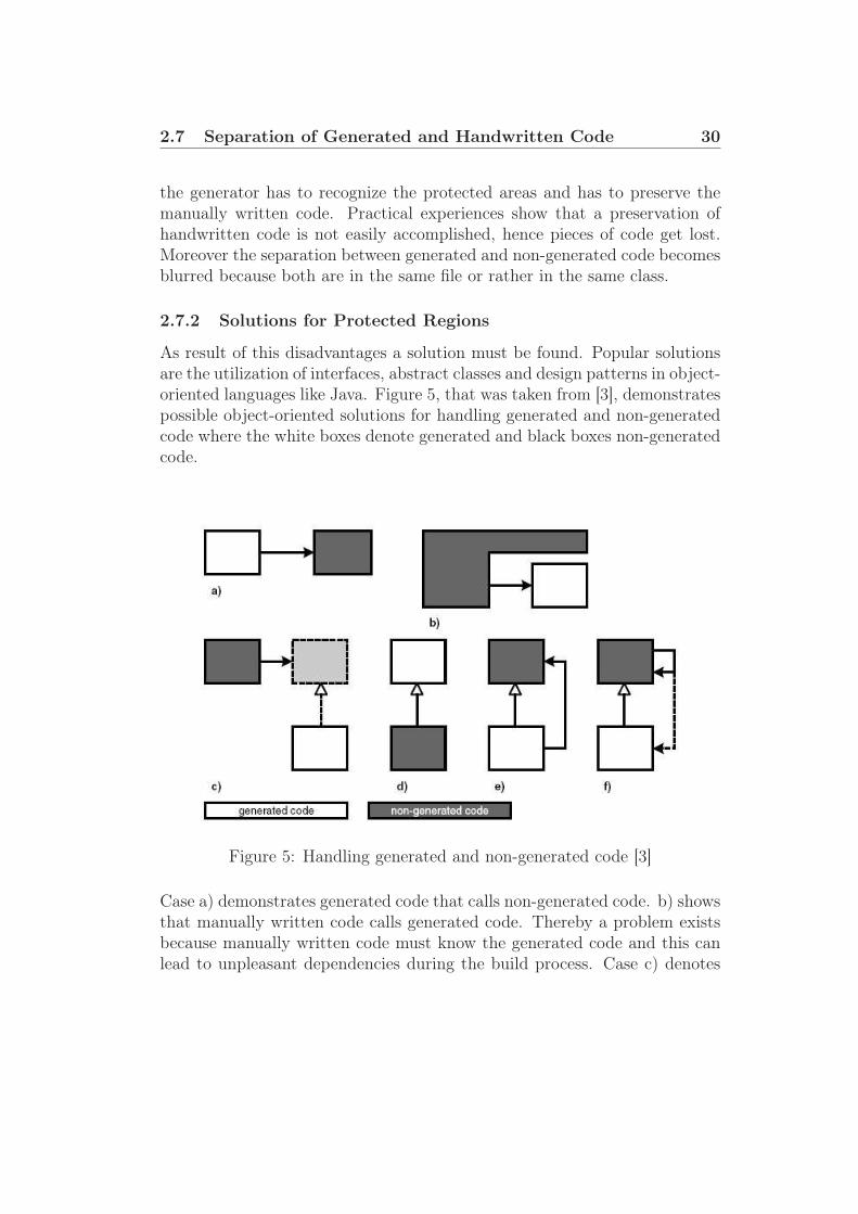
As result of this disadvantages a solution must be found. Popular solutionsare the utilization of interfaces, abstract classes and design patterns in object-oriented languages like Java. Figure 5, that was taken from [3], demonstratespossible object-oriented solutions for handling generated and non-generatedcode where the white boxes denote generated and black boxes non-generatedcode.
Figure 5: Handling generated and non-generated code [3]
Case a) demonstrates generated code that calls non-generated code. b) showsthat manually written code calls generated code. Thereby a problem existsbecause manually written code must know the generated code and this canlead to unpleasant dependencies during the build process. Case c) denotes

2.7 Separation of Generated and Handwritten Code 31
that generated code can inherit from handwritten code or implement anhandwritten interface. d) shows an implementation call that inherits fromthe generated class. e) depicts that a generated class can inherit from anon-generated class or invoke its operations. Case f) shows that manuallywritten classes call operations of generated subclasses.
If files with generated code are never modified, the generated can can simplybe overwritten in subsequent generator runs. Protected regions should beused if generated code must be modified manually. [3] gives the followingimportant advices:
Keep generated and non-generated code in separate files!Never modify generated code!
These statements discourage from the usage of protected regions. Protectedregions should only be used if the target platform does not support any otheroptions to place manually written code within generated code.

32
3 Related Work
A lot of work is done in the field of an automated generation of Web ap-plications based on a MDA. We mention the three papers [19], [21] and [22]because they have something in common. All those works are concentrated onWeb applications based on the MVC pattern. They introduced meta-modelsfor the Model, the View as well as the Controller. Paper [24] describes themodeling of Web applications based on Java and XML technologies. [23]introduce a methodology for testing Web applications. Furthermore [25] de-scribes JBoss Seam that offers facilities to model the pageflow of a Webapplication.
Paper [19] introduces the WebSA as well as the UWE (UML-based Web En-gineering) approaches for the model-driven development of Web applications.The WebSA approach aims to avoiding gaps between Web design models andthe final implementation. It covers all phases of the development process ofWeb applications where the focus lies on the software architecture. Besides itdefines a set of architectural models for the specification of the architecturalviewpoint. Furthermore it establishes an instance of the MDA developmentprocess. The WebSA approach is divided into three phases:
1. Analysis phaseThe analysis phase divides the Web application into the functional andarchitectural viewpoints. The functional perspective is given by Webfunctional models provided by Web methods. The architectural viewcontains a subsystem model and a configuration model to define thesoftware architecture of the Web application.
2. PIM-to-PIM transformationsThe analysis models are transformed to platform independent designmodels. The output is an integration model that contains informationabout the functionality and architecture.
3. PIM-to-PSM transformationsThe model transformations for each platform are built-up on the inte-gration model. The output of this phase is the specification of the Webapplication for a given platform.

33
The UWE approach defines a meta-model that acts as a conservative exten-sion of the UML meta-model that has a mapping to an UML profile. UWEseparates the modeling of different points of view into content, navigationstructure, business process and presentation. The content is modeled byUML class diagrams. The navigation structure is based on all conceptualclasses that are relevant for the navigation structure and represents the navi-gation paths. The behavior of the business logic describes the processflow inUML activity diagrams. The presentation model is used to sketch the layoutof the web pages.
[20] uses the WebSA approach to achieve a logical architectural view for Webapplications. Three models are defined by the WebSA approach that are re-sponsible for the definition of the logical components and their relationshipswithin a system.
• Subsystem Model (SM)The Subsystem Model reduces the complexity of the Web applicationby providing an abstract perspective of the logical architectural view.Subsystems obtained in this phase are later identified with each logicallayer in the application.
The subsystem model is divided into subsystems and dependency rela-tionships. Subsystems define groups of software components to supportthe functionality of certain logical layer. Dependency relationships de-scribe the relationship between subsystems.
• Web Component Configuration Model (WCCM)The WCCM consists of abstract elements that are produced in therefinement process performed on each subsystem. It contains abstractcomponents as well as abstract connectors. Abstract components areabstractions of one or more software components with shared func-tionalities. Abstract connectors represent dependency relationships be-tween two abstract components.
Architectural design patterns are used for powerful configurations, reusemechanisms and contributions to more efficient development processes.
• Web Component Integration Model (WCIM)For the connection of functional and architectural views under a com-

34
mon set of concrete components the WCIM is used. It is defined duringthe WebSA platform-independent phase. The WCIM consists of Con-crete Components (CC), Modules (M) and Concrete Connectors (CN).CCs represent software components in a certain application domain.Ms are containers of one or more concrete elements. CNs express therelationship between two CCs.
Muller et al. [21] deal with the question of making a new meta-model orto customize an existing one. Customizing existing meta-models is knownunder the term Profiling. They are coming to the following conclusion:
Creating a new meta-model makes more sense than profiling when the se-mantic distance between existing UML modeling elements and newly definedmodeling elements is becoming too large.
Furthermore a separation into three meta-models is described:
• Business ModelThe Business Model is built-up on the entity-based structural modelintroduced by paper [22]. UML class diagrams are used to represent thebusiness classes. Furthermore the business model is used to describesession management, personalization, search or statistics. An actionlanguage Xion is introduced which describes the behavior of classesrepresented by their methods. Xion is based on the syntax of OCLaugmented with Java-like control structures and affections. Xion isused to create, update and delete instances at runtime.
• Hypertext ModelThe Hypertext Model is an abstract description of composition of Webpages and navigation between Web pages. In other words, it describeshow Web pages are linked and built. The composition describes theway the various Web pages are composed from other pages as wellas the inclusion of information coming from the business model. Thenavigation describes the links and specifies the parameters betweenWeb pages.
• Presentation ModelThe Presentation Model is responsible for the graphical appearance ofthe Web pages.

35
The Web Modeling Language (WebML) is introduced in paper [22]. WebMLis based on four Models:
• Structural ModelThe Structural Model is responsible for the data content of a Web page.
• Hypertext ModelThe Hypertext Model consists of the Composition and Navigation Mod-els. The Composition Model specifies which pages compose the hyper-text and which content units make up a page. The Navigation Modeldescribes how pages and contents are linked to form the hypertext.
• Presentation ModelThe Presentation Model expresses the layout and graphical appearanceof the Web pages.
• Personalization ModelThe Personalization Model administrates user and user groups. Hence,contents can be stored user- or group-specific.
Chung and Lee [24] describe the modeling of Web applications using Java andXML related technologies. They consider Web applications that are built-ona three-tier architecture. Visual models are proposed and analyzed basedupon criteria for relative model comparison. Two criteria are proposed: thedegree of language independence and the degree of location independence.Furthermore comparison criteria are used to figure out how relatively difficultit is to model which component. A component means a physical and replace-able part of a system. To compare the modeling complexity of componentsthe Rational Unified Process (RUP) in companion with UML is applied. Byapplying RUP to a software system the architectural views of models can beachieved.
Alava et al. [23] introduce a methodology to test Web applications based ona Design View (DView) of the pageflow model. A DView is a representationof the pageflow based on graphs. The methodology extracts information froma pageflow model and creates a Typed Attributed Directed Graph (TGraph)that is used in the analysis of test coverage criteria. TGraphs are used to

36
model an object-oriented view of the system where vertices and edges rep-resent objects and relationships. TGraphs are used to apply traditional testcoverage criteria in terms of Action, Forward, Link and Page are the testcoverage criteria that are used by TGraphs. Action maps incoming HTTPrequests to the corresponding methods for execution. Forward representsa destination to which the pageflow controller might be directed to. Linksrepresent the actual HTTP request from the JSP pages to the Actions. APage is a JSP page that handles user interfaces. A TGraph is transformed toan Attributed Directed Graph (AGraph) and the resulting graph is analyzedto obtain traditional structural testing criteria.
JBoss Seam [25] provides the business process manager jBPM to representbusiness processes or user interactions as graphs. The graphs are defined inan XML dialect, called jPDL. jPDL is suitable to define the pageflow of aWeb application. Seam provides two ways to define the pageflow:
• JSF/SeamJSF/Seam provides a stateless definition of the pageflow. The statelessmodel defines a set of named, logical outcomes of events (buttons andlinks on Web pages). Each event is bonded to an action listener methodthat must make decisions of the pageflow, since only they have accessto the current state of the Web application.
• jPDLjPDL provides a stateful model that defines a set of transactions be-tween a set of named, logical Web application states. It is possible towrite action listener methods that are completely unaware of the flowof interactions because the flow of any user interaction can be expressedentirely in the jPDL pageflow definition.
JSF/Seam navigation rules are much simpler but the underlying Java codeis more complex to understand. On the other hand, jPDL makes user inter-actions immediately understandable without looking to the JSP or Java code.
Stateful models are more constrained. For logical state there are a con-strained set of possible transactions to other states. The stateless model ismore suitable to relatively unconstrained navigation rules where the user de-cides which Web page to display next, not the application.

37
Like mentioned above, this approaches can help us for further work. Mainlyfor modeling the Model component of the MVC pattern for an automatedgeneration of fetching data, e.g. from databases. The next section describesour approach of modeling Web application.

38
4 Description of our Approach
With all this theoretical background about the JSF framework and MDA,it is time to make something useful of it. This section describes our definedmeta-model that defines the DSL as well as the process of generating a JSFWeb application based on a given model that is an instance of the definedmeta-model. Furthermore a prototype of a JSF Web application is introducedthat demonstrates the functioning of our approach.
4.1 The Meta-Model
Page
−name : String−stylesheet : String [0..1]
OutputPage
−name : String−description : String−isPassword : boolean = false−type : String
TextField
InputPage
Form
−name : String−scope : String = session
NavigationRule
If
−outcome : String
Decision
WebApplication
−name : String
SubmitButton
−name : String−value : String−methodname : String
Link
−name : String−value : String−methodname : String
ElseIf
−outcome : String
Else
StaticText
Text
−name : String
DynamicText
gotopage
navigationrule1
navigationrule1
1
0..*
1
link
0..*
dynamictext
0..*
0..*
textfield
1..*
submitbutton
1
startpage
1 1..*
staticttext1..*
form1
0..1
Figure 6: Metamodel

4.1 The Meta-Model 39
Figure 6 shows our defined meta-model illustrated by an UML class diagram.A certain Web application is an instance of this meta-model. Our meta-modelprovides the modeling of Web pages as well as the modeling of the pageflow.First we will describe the parts of our meta-model that are responsible formodeling the Web pages.
4.1.1 Modeling of Web pages
Page
−name : String−stylesheet : String [0..1]
WebApplication
−name : String
startpage
1 1..*
Figure 7: Relation between a WebApplication and Pages
Each WebApplication consists of:
• An attribute name of type String that specifies the name of the Webapplication.
• A startpage and
• one or more (1..*) Pages.
The relationships between the classes WebApplication and Page is illus-trated in Figure 7.

4.1 The Meta-Model 40
The class Page is responsible for Web pages characterized by the followingattributes:
• A name of type String:The attribute name contains the name of the Web page as well as thetitle.
• A stylesheet of type String:The stylesheet attribute is an optional attribute that can contain thefilename of an user-defined stylesheet for a certain page. If the stylesheetattribute is not given, the generator depicts a default stylesheet.
We divide Web pages into InputPages and OutputPages. This is depictedin Figure 8. An input-page contains components of user interfaces where theuser can enter data. On the other hand an output-page is only responsiblefor displaying data. Both can contain one or more (0..*) Links that areresponsible for the pageflow.
Page
−name : String−stylesheet : String [0..1]
OutputPageInputPage Link
−name : String−value : String−methodname : String
link
0..*
Figure 8: Division of Page into InputPage and OutputPage
The Link class contains the following attributes:
• A name attribute of type String that specifies the name of the linkcomponent,
• a value of type String that captures the link and

4.1 The Meta-Model 41
• a methodname of type String that contains the name of the methodof a Java Bean that is responsible for delivering the outcomings of thegiven link.
Now we will take a closer look to input-pages. An InputPage consists ofone (1) Form. A Form contains one or more (1..*) TextFields and one (1)SubmitButton. These relationships are demonstrated in Figure 9.
TextField
−name : String−description : String−isPassword : boolean = false−type : String
Form
−name : String−scope : String = session
InputPage
SubmitButton
−name : String−value : String−methodname : String
textfield
1..*
submitbutton
1
form1
Figure 9: Composition of InputPage
A Form is described by the following attributes:
• A name of type String that indicates the name and
• A scope of type String that specifies the duration of validity of the en-tered data within the form. Valid values of the scope are: application,session, request and page.

4.1 The Meta-Model 42
A TextField consists of the following attributes:
• A name of type String that contains the name of the textfield,
• a description of type String that captures the textfield,
• an attribute isPassword of type boolean that indicates if the textfieldis a password field or not and
• a type of type String that specifies the type of the value of the textfield.Valid values are: int and String.
A SubmitButton is characterized by the following attributes:
• A name of type String that contains the name of the button,
• a value of type String that specifies the caption of the button and
• a methodname of type String that qualifies the method of a Java Beanthat is responsible for the outcome of the button.
Next, we will take a closer look to output-pages. Figure 10 demonstrates theconstitution of an output-page. An OutputPage consists of DynamicText
and StaticText. DynamicText and StaticText are composed to the classText that consists of the attribute name of type String that specifies thename of the text component.
The StaticText class is specified by the value attribute of type String
that contains the value of the static text. DynamicText fetches the valuefrom data that was entered by the user in a textfield. Hence an associationbetween DynamicText and TextField exists.

4.1 The Meta-Model 43
OutputPage
−name : String−description : String−isPassword : boolean = false−type : String
TextField
StaticText
Text
−name : String
DynamicText
1
0..*
staticttext
1..*
dynamictext
0..*
Figure 10: Composition of OutputPage
After modeling the Web pages of a Web application we can model the page-flow. The parts of our defined meta-model that are responsible for the mod-eling of the pageflow are described in the following section.

4.1 The Meta-Model 44
4.1.2 Modeling of the Pageflow
Due to the fact that only links and buttons are responsible for outcomingsthat define the pageflow we defined navigation rules that are associated withthe Link and SubmitButton classes. These associations are shown in Figure11.
Page
−name : String−stylesheet : String [0..1]
If
−outcome : String
NavigationRule
Decision
SubmitButton
−name : String−value : String−methodname : String
Link
−name : String−value : String−methodname : String
ElseIf
−outcome : String
Else
gotopage
1
navigationrule
1
navigationrule
1
0..*
0..1
Figure 11: Modeling of the Pageflow
Each SubmitButton and each Link consists of one or more (1..*) NavigationRules.Due to the fact that we wanted to achieve a process-oriented modeling of thepageflow, our meta-model contains classes that enable the pageflow model-ing through Java-like IF-ELSE statements. A NavigationRule consists ofone (1) If statement. The If class is specified by the outcome attribute oftype String that is responsible for the decision which Web page has to be

4.1 The Meta-Model 45
displayed next. An If can consist of one or more (0..*) ElseIf statements.Each ElseIf statement consists of an outcome attribute that has the samesignification as the outcome attribute for the If class. Furthermore an If
statement can consist of an (0..1) Else statement. If, ElseIf and Else arecomposed to the Decision class that is associated with the Page class thatdefines the Web page that has to be displayed next.
Our defined meta-model provides possibilities to model the Web pages aswell as the pageflow of a Web application. How a modeled Web applicationis generated based on our defined meta-model is described in the followingsection.

4.2 Code Generation with oAW 46
4.2 Code Generation with oAW
oAW provides a helpful plug-in for Eclipse ([13]) to generate a Web applica-tion based on a given model. Like mentioned in the Theory section, the oAWcore consists of a number of features. The main part of the code generatorbuilds the workflow that is described in the following section.
4.2.1 Workflow
The workflow builds the engine of the code generator. Like described in theTheory section, the workflow can consist of a number of components. Ourworkflow consists of seven components that are responsible to generate cer-tain parts of the Web application. Furthermore our Workflow uses a propertyfile that contains the name of the XMI file where the model is located as wellas the path where the generated code should be placed. The name of theproperty file is specified by the file attribute within the <property> tag.The following listing depicts an example for a property file:
model = model.xmi
srcGenPath = src -gen
Listing 11: Workflow property file
The main components of our workflow to generate a Web application are:
• XMI Reader Component
The XMI Reader component reads a given model that is specifiedby the <modelFile> tag and puts it into the outputSlot. Further-more our defined meta-model must be passed to the XMI Reader com-ponent. This is done by the <metaModelFile> tag. Now the inputmodel can be referenced by the value attribute specified within the<outputSlot> tag. The following listing demonstrates the definitionof the XMI Reader component.
<component class ="org.openarchitectureware.emf.XmiReader">
<!-- Specify the Meta -Model -->
<metaModelFile value =" metamodel/MetaModel.ecore" />
<!-- Specify the Model -->
<modelFile value ="${model }" />

4.2 Code Generation with oAW 47
<!-- Load model into outputSlot -->
<outputSlot value =" model" />
</component >
Listing 12: The XMI Reader Component of the Workflow
• Check Component
The second component of the workflow is the Check component thatis used for model validation. The Check component needs the meta-model that is specified by the <metaModel> tags. The meta-modelserves as basis for the model validation. Furthermore the check file hasto be specified. This is done by the <checkFile> tag within the Checkcomponent. The Check component requires the given model as inputthat has to be validated. This is specified through the <expression>
tag. The value attribute accords to the value of the <outputSlot> tagof the XMI Reader component. The following listing demonstrates thedeclaration of the Check component within our defined Workflow.
<!-- COMPONENT: CHECK -->
<component id=" checker"
class ="org.openarchitectureware.check.CheckComponent">
<!-- Specify the Meta -Model -->
<metaModel class ="oaw.type.emf.EmfMetaModel"
metaModelPackage ="org.eclipse.emf.ecore.EcorePackage">
<metaModelFile value =" metamodel/MetaModel.ecore" />
</metaModel >
<!-- fully qualified name of the check -file (.chk) -->
<checkFile value ="check :: JSFChecks"/>
<!-- check the model against constraints -->
<!-- defined in the check -file -->
<emfAllChildrenSlot value ="model"/>
</component >
Listing 13: The Check Component of the Workflow
• Generator Components
The Generator components are responsible for the code generation.Again, the meta-model must be specified within the <metaModel> tag.The <expand> tag refers to a template that contains the transformation

4.2 Code Generation with oAW 48
rules that are responsible for the code generation. The template filesare described later in this section. The value attribute of the <expand>tag refers to the root of the template. Furthermore the path wherethe generated code should be placed is specified within the <outlet>
tag. Finally two code beautifiers are specified within the <beautifier>tags. Beautifiers beautify the generated code for improving the clarity.oAW supports two code beautifiers: a Java- and a XML-code beauti-fier. Due to the fact that we have to generate Java- and XML-code,both beautifiers are included within the particular generator compo-nent. The following listings describe our defined components that areresponsible for generating Web pages, Java Beans and the XML filethat contains information about the pageflow.
– Component to generate Web pages
<!-- COMPONENT to generate Web pages -->
<component
id=" generator"
class ="org.openarchitectureware.xpand2.Generator">
<!-- Specify the Meta -Model -->
<metaModel
class ="org.openarchitectureware.type.emf.EmfMetaModel">
<metaModelFile value =" metamodel/MetaModel.ecore" />
</metaModel >
<!-- Using Template for Code Generation -->
<expand value =" templates :: generatePages ::Root FOR model"/>
<!-- Specify Output Path -->
<outlet path="${srcGenPath }"/>
</component >
Listing 14: The Generator Component for Web pages
– Component to generate Java Beans
<!-- COMPONENT to generate Java Beans -->
<component
id=" BeanGenerator "
class ="org.openarchitectureware.xpand2.Generator">
<!-- Specify the Meta -Model -->
<metaModel
class ="org.openarchitectureware.type.emf.EmfMetaModel">
<metaModelFile value =" metamodel/MetaModel.ecore"/>
</metaModel >

4.2 Code Generation with oAW 49
<!-- Using Template for Code Generation -->
<expand value =" templates :: generateBeans ::Root FOR model"/>
<!-- Specify Output Path -->
<outlet path="${srcGenPath }"/>
<!-- Code Beautifiers -->
<beautifier
class ="org.openarchitectureware.xpand2.output.JavaBeautifier "/>
</component >
Listing 15: The Generator Component for Java Beans
– Component to generate the Pageflow
<!-- COMPONENT to generate the Pageflow -->
<component
id=" PageFlowGenerator"
class ="org.openarchitectureware.xpand2.Generator">
<!-- Specify the Meta -Model -->
<metaModel
class ="org.openarchitectureware.type.emf.EmfMetaModel">
<metaModelFile value =" metamodel/MetaModel.ecore"/>
</metaModel >
<!-- Using Template for Code Generation -->
<expand
value =" templates :: generateFacesConfigXML ::Root FOR model"/>
<!-- Specify Output Path -->
<outlet path="${srcGenPath }"/>
<!-- Code Beautifier -->
<beautifier
class ="org.openarchitectureware.xpand2.output.XmlBeautifier "/>
</component >
Listing 16: The Generator Component for the Pageflow information
To validate a given model, the Check component of the Workflow is used.The definition of the check constraints within this project is described in thenext section.

4.2 Code Generation with oAW 50
4.2.2 Check - Model Validation
As mentioned in the Theory section, oAW provides a feature for model vali-dation that is called Check. All defined constraints must be located in a filewith the prefix .chk. The following listing shows a snippet of the check fileused in the course of this project:
import MetaModel;
context MetaModel :: WebApplication
ERROR ’a WebApplication must have a name!’:
this.name!=null;
context MetaModel :: WebApplication
ERROR ’invalid name for WebApplication !’:
name.length >0;
Listing 17: The chk file
This snippet checks if a name is given for WebApplication as well as thatthe name is not empty in the given model. Furthermore checks are done ifvalues are set correctly within the given model, e.g. the scope attribute ofa Form can only contain the values application, session, request or page.
After the given model is validated the process of code generation is accom-plished. The templates that are used as the basis for generating code aredescribed in the next section.
4.2.3 Xpand2 - Templates
oAW provides a special language called Xpand2 that is used in templates tocontrol the code generation. Templates must resist in files with the prefix.xpt. The tag brackets («,») are characters introduced by oAW to definecontrol sequences like FOREACH or IF within the template files to control thegeneration of code. The following listings describe the defined template fileswithin this project to generate the Web pages, the Java Beans as well as theXML file that contains the pageflow information.

4.2 Code Generation with oAW 51
• Template to generate Web pages
The following listing shows how Web pages are generated with an oAWtemplate file:
<<FOREACH inputpage AS p>>
<<FILE p.name +".jsp">>
<%@ taglib uri="http :// java.sun.com/jsf/html" prefix ="h" %>
<%@ taglib uri="http :// java.sun.com/jsf/core" prefix ="f" %>
<html >
<head >
...
</head >
<body >
<f:view >
<<EXPAND InputJSP FOR p>>
</f:view >
</body >
</html >
<<ENDFILE >>
<<ENDFOREACH >>
Listing 18: Template to generate Web pages
For each instance of the class InputPage we create a JSP file thatis equivalent to the name of the given input-page. First the tag li-braries for JSP are generated through the <taglib> tags. Afterwardsthe header information including the stylesheet is generated. Thenthe user interface components of an input-page are generated. Thatis achieved by calling the subrouting InputJSP. This subroutine is re-sponsible to generate JSP code for all instances of the Form, TextField,SubmitButton and Link classes. The following listing shows the sub-routine InputJSP.
<<DEFINE InputJSP FOR MetaModel ::InputPage >>
<h:form id="<<form.name >>">
<<FOREACH form.textfield AS tf >>
<!-- TEXTFIELD -->
<h:outputText id="<<tf.description >>"
value="<<tf.description >>" />
<<IF tf.isPassword >>
<h:inputSecret id="<<tf.name >>"
value ="#{ Generated <<name.toFirstUpper ()>>Bean.
<<tf.name >>}" />

4.2 Code Generation with oAW 52
<<ELSE >>
<h:inputText id="<<tf.name >>"
value ="#{ Generated <<name.toFirstUpper ()>>Bean.
<<tf.name >>}" />
<<ENDIF >>
<<ENDFOREACH >>
<!-- SUBMITBUTTON -->
<h:commandButton id="<<form.submitbutton.name >>"
action ="#{ Generated <<name.toFirstUpper ()>>Bean.
<<form.submitbutton.methodname >>}"
value="<<form.submitbutton.value >>" />
</h:form >
<!-- LINKS -->
<<FOREACH link AS l>>
<h:form >
<h:commandLink id="<<l.name >>"
action ="#{ Generated <<name.toFirstUpper ()>>Bean.
<<l.methodname >>}">
<h:outputText value="<<l.value >>" />
</h:commandLink >
</h:form >
<<ENDFOREACH >>
<<ENDDEFINE >>
Listing 19: Generating user interface components for InputPage
First we generate the JSF tags for each textfield. If the attribute is-Passwort of the TextField is set to true a password field is generatedotherwise a textfield. All Textfields get an id that is derived from thename attribute. Next the JSF tag for the SubmitButton is generated.The button gets an id, a value and an action. The action is linkedto a method of a Java Bean that is executed when the user pressedthe button and returns a certain outcome. The name of the method isgiven by the methodname attribute of the SubmitButton class. Finallythe JSF tags for links are generated. Similar to buttons the action ofa link is linked to a method of a Java Bean that is responsible for theoutcome of the link, hence for the pageflow.
After all input-pages are generated the generation of the output-pagescan start. The generation of output-pages is similar to the approachof generating input-pages. The only difference is that the subroutinefor generating the components of an output-page. The subroutine foroutput-pages is shown in the following listing:

4.2 Code Generation with oAW 53
<<DEFINE OutputJSP FOR MetaModel ::InputPage >>
<!-- STATIC OUTPUT TEXT -->
<<FOREACH staticoutputtext AS t>>
<h:outputText id="<<t.name >>"
value="<<t.value >>" /><br >
<<ENDFOREACH >>
<!-- DYNAMIC OUTPUT TEXT -->
<<FOREACH dynamicoutputtext AS t>>
<h:outputText id="<<t.name >>"
value="<<t.textfield >>" /><br>
<<ENDFOREACH >>
<!-- LINKS -->
<<FOREACH link AS l>>
<h:form >
<h:commandLink id="<<l.name >>"
action ="#{ Generated <<name.toFirstUpper ()>>Bean.
<<l.methodname >>}">
<h:outputText value="<<l.value >>" />
</h:commandLink >
</h:form >
<<ENDFOREACH >>
<<ENDDEFINE >>
Listing 20: Generate user interface components for OutputPage
The subroutine OutputJSP generates tags for each staticoutputtext
and for each dynamicoutputtext. The ids are the name of the labels.The difference between static and dynamic text is that the value of astatic text contains a String and a dynamic text is linked to the valueof a textfield of an input-page. Afterwards the JSF tags for links aregenerated similar to the subroutine for input-pages.
• Template to generate Java Beans
Java Beans are generated for each input-page as well as for each output-page that contain at least one link. Furthermore Java classes are gener-ated for each output-page containing links. The following listing showsa snippet of the template file:
<<FOREACH inputpage AS p>>
<<FILE "Generated "+p.name.toFirstUpper ()+" Bean.java">>
public class Generated <<p.name.toFirstUpper ()>>Bean {

4.2 Code Generation with oAW 54
public Generated <<p.name.toFirstUpper ()>>Bean() {}
<<EXPAND FormBeans FOR p.form >>
...
<<ENDFOREACH >>
Listing 21: Template to generate Java Beans
For each instance of the class InputPage we create a Java class that getsthe suffix Generated and the prefix Bean. This should help the pro-grammer to distinguish between generated classes and manually writtenclasses. First we create the constructor that is equivalent to the classname. Afterwards the subroutine FormBeans declares a variable foreach textfield within the form and generates get- and set-methods foreach variable.
The following listing describes the generation of methods that are linkedto buttons that are responsible for returning the outcomings:
<<IF p.form.submitbutton.navigationrule !=null >>
public String <<p.form.submitbutton.methodname >>() {
<<p.name.toFirstUpper ()>>Util util <<p.name.toFirstUpper ()>> =
new <<p.name.toFirstUpper ()>>Util ();
String strOutcome = util <<p.name.toFirstUpper ()>>.
<<p.form.submitbutton.methodname >>(
<<FOREACH p.form.textfield.name AS tf SEPARATOR ’,’>>
this.<<tf >>
<<ENDFOREACH >>);
...
Listing 22: Generating methods for each SubmitButton
We achieve that the programmer has to create for each input-page aJava class that accords to the name of the input-page with the prefixUtil. Furthermore the programmer must implement a method thatmatches the value of the methodname attribute of the SubmitButton
class. This method gets the values from the textfields as parametersand must return the defined outcomings in the given model. Therefor

4.2 Code Generation with oAW 55
we generate code that compares the returned String from the manuallywritten method. This is shown in the following listing:
<<IF p.form.submitbutton.navigationrule.if!=null >>
if(strOutcome.equals ("
<<p.form.submitbutton.navigationrule.if.outcome >>")) {
return "<<p.form.submitbutton.navigationrule.if.outcome >>";
}
<<IF p.form.submitbutton.navigationrule.if.elseif.size >0>>
<<FOREACH p.form.submitbutton.navigationrule.if.elseif AS ei >>
else if(strOutcome.equals("<<ei.outcome >>")) {
return "<<ei.outcome >>";
}
<<ENDFOREACH >>
<<ENDIF >>
<<IF p.form.submitbutton.navigationrule.if.else!=null >>
else {
return "*";
}
<<ELSE >>
return null;
<<ENDIF >>
<<ELSE >>
return null;
<<ENDIF >>
Listing 23: Generate outcomings for each method
To achieve the correct outcomings we have to define IF-ELSE state-ments that are derived from the process-oriented definition of the page-flow within the model. First, code is generated for the IF branch. Af-terwards is code generated for each ELSEIF branch. Finally the ELSE
branch is generated if it is given. Otherwise the method returns null
within the else branch. With this approach we achieve that the pro-grammer is responsible for returning the correct outcomings throughmanually written methods. Otherwise the wildcard * or null is re-turned that signifies that the current page is displayed again.
Thereby we solve the problem of dealing with generated and manuallywritten code because the programmer is responsible to validate the en-tered data in the textfields, e.g. by accessing a database. Moreover themanually written code does not become overwritten in a subsequentgenerator run because it exists outside the generated code.

4.2 Code Generation with oAW 56
To separate generated from manually written code we chose the provenapproach to call handwritten Java classes by generated code to avoidsevere effects in case of interventions in the model. Changes in the tem-plates lead to changes in the generated code. This can further leadsto the problem that the developer must change the manually writtenclasses that extend generated classes. To avoid this problem and de-crease the coupling of the generated and the manually written code wepropose the following solution: generated code calls methods of hand-written classes.
• Template to generate Pageflow information
The template to generate information about the pageflow generatesan XML file that serves as input for a Java Servlet that is provided bythe JSF framework. This Java Servlet is responsible for controlling thepageflow based on the outcomings of buttons and links. The followinglisting shows the template that generates the XML file:
<<FILE "faces -config.xml">>
...
<<FOREACH inputpage AS p>>
<<IF p.form.submitbutton.navigationrule !=null >>
<navigation -rule >
<from -view -id >/ pages/<<p.name >>.jsp </from -view -id >
<<EXPAND NavigationCase FOR
p.form.submitbutton.navigationrule >>
<<IF p.link.size >0>>
<<FOREACH p.link AS l>>
<<EXPAND NavigationCase FOR l.navigationrule >>
<<ENDFOREACH >>
<<ENDIF >>
</navigation -rule >
<<ENDIF >>
<<ENDFOREACH >>
<<FOREACH outputpage AS p>>
<<IF p.link.size >0>>
<navigation -rule >
<from -view -id >/ pages/<<p.name >>.jsp </from -view -id >
<<FOREACH p.link AS l>>
<<EXPAND NavigationCase FOR l.navigationrule >>
<<ENDFOREACH >>
</navigation -rule >
<<ENDIF >>

4.2 Code Generation with oAW 57
<<ENDFOREACH >>
Listing 24: Template to generate Pageflow information
First we generate information about the pageflow for each InputPage.Information about the outcomings delivered from the method of theSubmitButton is generated. Therefor the subroutine NavigationCase
is called. Aftwards information about the outcomings delivered fromthe Links is generated. The NavigationCase is called for each link.After generating the pageflow information for each input-page the page-flow information for each OutputPage is generated. This is similar toInputPage. The following listing shows the subroutine NavigationCase:
<<DEFINE NavigationCase FOR MetaModel :: NavigationRule >>
<navigation -case >
<from -outcome ><<if.outcome >></from -outcome >
<to -view -id >/ pages/<<if.gotopage.name >>.jsp </to-view -id >
</navigation -case >
<<IF if.elseif.size > 0>>
<<FOREACH if.elseif AS e>>
<navigation -case >
<from -outcome ><<e.outcome >></from -outcome >
<to -view -id >/ pages/<<e.gotopage.name >>.jsp </to -view -id >
</navigation -case >
<<ENDFOREACH >>
<<ENDIF >>
<<IF if.else!=null >>
<navigation -case >
<from -outcome >*</from -outcome >
<to -view -id >/ pages/<<if.else.gotopage.name >>.jsp </to-view -id >
</navigation -case >
<<ENDIF >>
<<ENDDEFINE >>
Listing 25: Generating navigation-cases
First we generate the navigation-cases for the IF branch of the process-oriented defined pageflow. A navigation-case consists of an outcomeand a Web page that has to be displayed by the certain outcome. Af-terwards the navigation-cases for each ELSEIF branch are generated.Finally the ELSE branch outcome is generated.

4.2 Code Generation with oAW 58
After generating Web pages, Java Beans and information about thepageflow an Apache Ant file is generated that facilitates the deploy-ment of the generated JSF Web application on the Apache TomcatWebserver. The generation of the Ant file is described next.
• Template to generate the Apache Ant File
This template is used to generate the build.xml file that is executedby the developer using Apache Ant. Apache Ant is used to ease thedeployment of the generated Web application on the Apache TomcatWeb server. Listing 26 shows a snippet with the main components ofthe template that generates the build.xml file.
<<DEFINE Root FOR MetaModel::WebApplication >>
<<FILE name+"\\ant\\ build.xml">>
<project name="jsf" basedir="../" default="deploy">
<property file="ant/build.properties" />
...
<!-- Deploy Web application -->
<target name="deploy" depends="war">
<copy file="${ build.dir }/${ project.distname }.war"
todir="${ tomcat.dir}" />
</target >
<!-- Create WAR file -->
<target name="war" depends="build">
<mkdir dir="${ build.dir}" />
<war basedir="${ webroot.dir}"
warfile="${build.dir }/${ project.distname }.war"
webxml="${ webinf.dir}/web.xml">
<exclude name="WEB -INF/${ build.dir }/**"/>
<exclude name="WEB -INF/src /**"/>
<exclude name="WEB -INF/web.xml"/>
</war>
</target >
<!-- Build entire project -->
<target name="build" depends="prepare ,compile"/>
<target name="prepare">
<tstamp/>
</target >
<!-- Compile Java files -->
<mkdir dir="${ webinf.dir}/ classes" />
<target name="compile" depends="prepare ,resources">

4.2 Code Generation with oAW 59
<javac srcdir="JavaSource" destdir="${ webinf.dir}/ classes">
<classpath refid="compile.classpath"/>
</javac >
</target >
...
</project >
<<ENDFILE >>
<<ENDDEFINE >>
Listing 26: Generating the Apache Ant file build.xml
The build.xml file is located in the ant directory of the generated Webapplication. Like mentioned in the Theory section, an Apache Antfile consists of multiple targets. Our generated Ant file has a deploy
target that is set to default in the attributes of the <project> tag.The deploy target depends on the war target. The war target is usedto create a war file that is copied to the webapps directory of theApache Tomcat Web server within the deploy target. The war targetdepends on the build target that is used to compile the Java sourcefiles. The compilation of the Java files results in errors if the developerdoes not implement the Java classes in which the called methods relythat are called by the generated Java Beans. After compiling the Javasources the war file is created and copied to the webapps directory ofthe Apache Tomcat Web server. Our generated build.xml file uses aproperties file that is specified within the <property> tag at the topof the build.xml file. The property file contains all needed directoriesof the build.xml file, e.g. ${build.dir}.
After the JSF Web application is generated the developer can deploy thegenerated Web application using the Ant file. Ant checks if the developerimplemented all needed classes and methods called by the generated JavaBeans. By starting the Apache Tomcat Web server the war file is extractedand the whole JSF Web application relies in the webapps directory. Todemonstrate the functioning of our approach a prototype JSF Web applica-tion was generated that is described in the following section.

4.3 A Prototype for Visualizing the Mode of Operation 60
4.3 A Prototype for Visualizing the Mode of Operation
In this section we want to introduce a prototype to demonstrate the func-tioning of our approach. The prototype features a JSF Web application thatcan be deployed on the Apache Tomcat Web server. Our prototype picturesa Web application that consists of a registration feature. To login to a certainWeb application, a user has to register first. A model-driven development ofsuch a registration Web application is demonstrated by our prototype.
First, the Web application that should be generated must be described ina model. Figure 12 shows the UML class diagram of a Web page that con-tains a form for user registration.
<<WebApplication>>
Register Web Application
<<Link>>
LostPassword
−lostPassword : methodname−Lost Password : Value
<<TextField>>
Surname
−surname : Description−false : IsPassword−String : Type
<<SubmitButton>>
RegisterButton
−Register : Value−registerUser : methodname
<<InputPage>>
Register
<<Form>>
RegisterForm
<<TextField>>
−e−mail : Description−false : IsPassword−String : Type
<<TextField>>
Forename
−forename : Description−true : IsPassword−String : Type
11
1
1
startpage
1 1
1 1
Figure 12: Model of a Web page

4.3 A Prototype for Visualizing the Mode of Operation 61
The class Register Web Application has the stereotype «WebApplication»that was introduced by the meta-model. The class Register with the stereo-type «InputPage» is denoted as an input-page as well as the start-page ofthe Web application. The page Register consists of one (1) Form and one(1) Link. The RegisterForm consists of one (1) Forename textfield, one(1) Surname textfield, one (1) EMail textfield and one (1) RegisterButton.The attribute methodname of RegisterButton is set to registerUser thatdenotes the methodname of the Java Bean that has to be executed if the but-ton is pressed. The LostPassword link utilizes the method lostPassword.These methods are described later in this section.
Analog to the Register Web page all Web pages of the Web application mustbe modeled. Our prototype consists of the following Web pages beside theRegister Web page:
• thanks.jsp
This page is displayed after the registration was successful. The Webpage thanks.jsp is an output-page that contains a static text as wellas a link.
• failed.jsp
This page is displayed when the registration failed, e.g. the enterede-mail address already exists in the database. failed.jsp is an output-page with a static text and a link like the Web page thanks.jsp.
• lost.jsp
The Web page lost.jsp is an input-page and contains a form wherethe user can enter an e-mail address to which the password should besent.
• login.jsp
The Web page login.jsp is an input-page that contains textfields wherethe user can enter the e-mail address and the corresponding passwordto login a Web application.

4.3 A Prototype for Visualizing the Mode of Operation 62
A graphical representation of the pageflow of our prototype is shown in Fig-ure 13.
register.jsp thanks.jsp
failed.jsp lost.jsp
login.jsp
lostPasswort
failed
success
back
back
success
gotoLogin
failed
Figure 13: Pageflow of our Prototype
The subsequent Web pages of register.jsp dependent on the outcome ofthe RegisterButton and the LostPassword link. If the outcome of theRegisterButton is success, thanks.jsp is displayed next. Otherwise, if theoutcome is failed the failed.jsp Web page is displayed. If the user clicksthe LostPassword link that delivers the outcome lostPassword, lost.jsp isdisplayed.
The output-page thanks.jsp consists of two links with the outcomings go-toLogin and back. If the user clicks the Goto Login link, the outcome isgotoLogin and the user is forwarded to login.jsp Web page. Else if the userclicks the Back link that delivers the outcome back, the register.jsp Webpage is displayed next.
The output-page failed.jsp consists only of the Back link that delivers theoutcome back. The register.jsp Web page is displayed next.
The input-page login.jsp does not deliver outcomings in our prototype be-cause it acts as an interface to an Web application where the user has tologin first before using the functionality of this Web application.

4.3 A Prototype for Visualizing the Mode of Operation 63
<<Link>>
LostPassword
−lostPassword : methodname−Lost Password : Value
<<InputPage>>
Register
<<ElseIf>>
ElseIf
−failed : Outcome
<<NavigationRule>>
NavigationRule
<<SubmitButton>>
RegisterButton
−Register : Value−registerUser : methodname
<<Form>>
RegisterForm
<<NavigationRule>>
NavigationRule
<<If>>
If
−lostPassword : Outcome
<<If>>
If
−lostPassword : Outcome
<<OutputPage>>
Failed
<<InputPage>>
Lost
<<OutputPage>>
ThanksgotoPage
gotoPage
11
gotoPage
1
1
1
1
1
1
Figure 14: Modeling of Pageflow for the Register Web page
Figure 14 demonstrates the modeling of the pageflow for the RegistrationWeb page. Like mentioned before, the Web page Register consists of aRegisterForm with a RegisterButton and of a LostPassword link. Navi-gation rules are assigned to buttons and links. The RegisterButton containsone (1) NavigationRule that consists of one (1) If branch. The modeled If
branch defines if the Outcome is success than gotoPage Thanks. The ElseIfbranch defines if the Outcome is failed than gotoPage Failed.

4.3 A Prototype for Visualizing the Mode of Operation 64
The pageflow modeling for a Link is analog to the modeling of the pageflowfor a SubmitButton. The LostPassword link consists of one (1) NavigationRulethat consists of one (1) If branch. The modeled If branch defines if theOutcome is lostPassword than gotoPage LostPassword.
The modeling of the pageflow for the Web pages thanks.jsp, failed.jsp,lostPassword.jsp and login.jsp is analog to the pageflow model of theregister.jsp Web page demonstrated in Figure 14.
After modeling the Web application we can start to generate the Web ap-plication. The following section shows the generated Web pages, Java Beansand pageflow information generated by our created templates.
4.3.1 The Generated Prototype Web Application
Each generated Web application contains the following directory structure./<WebApplicationName >
/ant
build.xml
/JavaSource
/WebContent
/pages
jsf -impl.jar
jsf -api.jar
/lib
/WEB -INF
faces -config.xml
web.xml
Listing 27: Generated directory structure
Each Web application consists of three directories:
• ant
The ant directory contains an Ant build file named build.xml. This fileis responsible for compiling the Java classes as well as to generate awar file that can be deployed on an Apache Tomcat Web server.
• JavaSource
The JavaSource directory contains all generated Java Beans. JavaBeans are generated for each input-page as well as for each output-page that contains at least one link.

4.3 A Prototype for Visualizing the Mode of Operation 65
• WebContent
The WebContent directory contains of the pages directory that con-tains all generated Web pages. Moreover it contains a lib directorythat holds Java libraries (jar files required by the JSF Web pplication.The lib directory contains the Java library files jsf-impl.jar andjsf-api.jar. These files are needed by every JSF Web application be-cause they contain Java classes that are needed by the JSF framework,e.g. the FacesServlet Servlet that controls the pageflow. Furthermorethe WebContent directory consists the WEB-INF directory that containsconfiguration files for the JSF framework and the Apache Tomcat Webserver. The faces-config.xml file contains information about the page-flow of the generated Web application as well as information about allJava Beans that are used within the Web application. faces-config.xmlis utilized as input for the FacesServlet of the JSF framework thatcontrols the pageflow. The web.xml is a configuration file for the Webapplication that runs on the Apache Tomcat Web server. This file isused to include the FacesServlet in the JSF Web application.
4.3.1.1 Generated Web Pages
The following listing shows the generated register.jsp Web page.<%@ taglib uri="http :// java.sun.com/jsf/html" prefix ="h" %>
<%@ taglib uri="http :// java.sun.com/jsf/core" prefix ="f" %>
<html >
<head > ... </head >
<body >
<f:view >
<h:form id=" registerForm">
<h:outputText id=" Forename" value =" Forename" />
<h:inputText id=" forename"
value ="#{ GeneratedRegisterBean.forename }" />
<h:outputText id=" Surname" value =" Surname" />
<h:inputText id=" surname"
value ="#{ GeneratedRegisterBean.surname }" />
<h:outputText id="E-Mail" value ="E-Mail" />
<h:inputText id=" email"
value ="#{ GeneratedRegisterBean.email }" />
<h:commandButton id=" btnRegister"
action ="#{ GeneratedRegisterBean.registerUser }"
value =" Register" />
</h:form >
<h:form >
<h:commandLink id=" lostPassword"
action ="#{ GeneratedRegisterBean.lostPassword }">
<h:outputText value ="Lost Password ?" />

4.3 A Prototype for Visualizing the Mode of Operation 66
</h:commandLink >
</h:form >
</f:view >
</body >
</html >
Listing 28: Generated register.jsp
The register.jsp Web page contains a form with textfields and a button aswell as a link. All user interface components are within the <f:view> tag.Buttons and links are bound to methods of a Java Bean that is generatedfor the certain Web page. Those methods are executed if the user pressesthe button or clicks the link. Furthermore, those methods are responsiblefor the outcomings of the Web page. The outcome builds the basis for thedecision which Web page has to be displayed next. The graphical appearanceof register.jsp is shown in Figure 15.
Figure 15: register.jsp
All Web pages are generated analog to the register.jsp Web page. The fol-lowing figures demonstrate the graphical appearance of the other generatedWeb pages of our prototype.
Figure 16 shows the thanks.jsp Web page that is displayed if the regis-ter.jsp Web page delivers the outcome success. thanks.jsp consists of astatic output text that displays the string Thank you!. thanks.jsp consists

4.3 A Prototype for Visualizing the Mode of Operation 67
also of a back link that is used to display register.jsp again. Furthermorethanks.jsp has a login link that is responsible to display the login.jsp Webpage.
Figure 16: thanks.jsp
Figure 17 shows the failed.jsp Web page that is displayed if the register.jspWeb page delivers the outcome failed. failed.jsp consists of a static out-put text that displays the string Registration failed!. failed.jsp consistsalso of a back link that is used to display register.jsp again.
Figure 17: failed.jsp

4.3 A Prototype for Visualizing the Mode of Operation 68
Figure 18 shows the lost.jsp Web page that is displayed if the user clicks theLost Password link of the register.jsp Web page. lost.jsp is an input-pagethat contains a form with a textfield and a button. The textfield is used forthe user to enter an e-mail address if the user has forgotten the password.The method of the Java Bean bounded to the button is responsible to checkthe entered e-mail address and deliver an outcome. Depending on the out-come the login.jsp or failed.jsp Web page is displayed next.
Figure 18: lost.jsp
Figure 19 shows the login.jsp Web page that contains a form where the usercan enter the e-mail address and the password.
Figure 19: login.jsp

4.3 A Prototype for Visualizing the Mode of Operation 69
The following section depicts the generated Java Beans of our prototypethat are responsible to store the entered values in textfields as well as for thedelivery of the outcome of a certain Web page.
4.3.1.2 Generated Java Beans
Java Beans are generated for each input-page as well as for each output-page that contains links. Java Beans are responsible for the Model of theMVC pattern. Thus, Java Beans are used to fetch the by the Web applica-tion needed data, e.g. accessing a database. Due to the fact that we onlygenerate Web pages as well as information about the pageflow, the developeris responsible for fetching data. Hence we have to generate code within theJava Beans that calls a method of a Java class that has to be implementedby the developer.
The following source code listing shows the generated Java Bean for theregister.jsp Web page.public class GeneratedRegisterBean {
private String forename;
private String surname;
private String email;
public GeneratedRegisterBean () {}
public void setForename(String forename) {
this.forename = forename;
}
public String getForename () {
return this.forename;
}
public void setSurname(String surname) {
this.surname = surname;
}
public String getSurname () {
return this.surname;
}
public void setEmail(String email) {
this.email = email;
}
public String getEmail () {
return this.email;
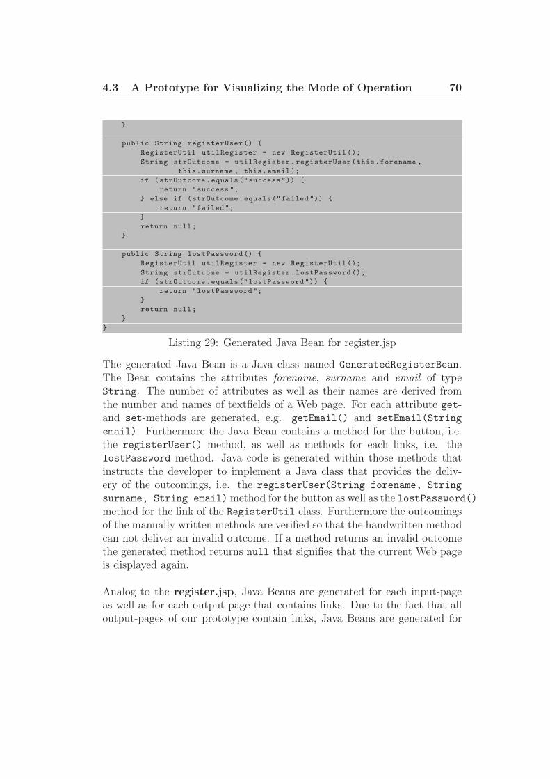
4.3 A Prototype for Visualizing the Mode of Operation 70
}
public String registerUser () {
RegisterUtil utilRegister = new RegisterUtil ();
String strOutcome = utilRegister.registerUser(this.forename ,
this.surname , this.email );
if (strOutcome.equals (" success ")) {
return "success ";
} else if (strOutcome.equals (" failed ")) {
return "failed ";
}
return null;
}
public String lostPassword () {
RegisterUtil utilRegister = new RegisterUtil ();
String strOutcome = utilRegister.lostPassword ();
if (strOutcome.equals (" lostPassword ")) {
return "lostPassword ";
}
return null;
}
}
Listing 29: Generated Java Bean for register.jsp
The generated Java Bean is a Java class named GeneratedRegisterBean.The Bean contains the attributes forename, surname and email of typeString. The number of attributes as well as their names are derived fromthe number and names of textfields of a Web page. For each attribute get-and set-methods are generated, e.g. getEmail() and setEmail(String
email). Furthermore the Java Bean contains a method for the button, i.e.the registerUser() method, as well as methods for each links, i.e. thelostPassword method. Java code is generated within those methods thatinstructs the developer to implement a Java class that provides the deliv-ery of the outcomings, i.e. the registerUser(String forename, String
surname, String email) method for the button as well as the lostPassword()method for the link of the RegisterUtil class. Furthermore the outcomingsof the manually written methods are verified so that the handwritten methodcan not deliver an invalid outcome. If a method returns an invalid outcomethe generated method returns null that signifies that the current Web pageis displayed again.
Analog to the register.jsp, Java Beans are generated for each input-pageas well as for each output-page that contains links. Due to the fact that alloutput-pages of our prototype contain links, Java Beans are generated for

4.3 A Prototype for Visualizing the Mode of Operation 71
each Web page.
The following section describes the generated file that contains informationabout the pageflow as well as information about all Java Beans used withinthe Web application.
4.3.1.3 Generated Pageflow Information
The JSF framework consists of a Java Servlet FacesServlet that controlsthe pageflow. This Servlet needs as input an XML file that describes thepageflow the Java Beans that are used within the Web application.
The following listing depicts the generated information about the pageflowfor the register.jsp Web page.<navigation -rule >
<from -view -id >/ pages/register.jsp </from -view -id >
<navigation -case >
<from -outcome >success </from -outcome >
<to -view -id >/ pages/thanks.jsp </to -view -id >
</navigation -case >
<navigation -case >
<from -outcome >failed </from -outcome >
<to -view -id >/ pages/failed.jsp </to -view -id >
</navigation -case >
<navigation -case >
<from -outcome >lostPassword </from -outcome >
<to -view -id >/ pages/lost.jsp </to -view -id >
</navigation -case >
</navigation -rule >
Listing 30: Generated information about Pageflow
For each Web page that delivers outcomings a <navigation-rule> tag mustbe generated. The <from-view-id> tag specifies the name of the Web page.For each outcome a <navigation-case> tag must be generated that consistsof a <from-outcome> tag and a <to-view-id> tag. The <from-outcome>
tag specifies the outcome and the <to-view-id> tag specifies which Webpage has to be displayed for this outcome.
The register.jsp Web page has the outcomings success, failed andlostPassword. Dependent on the outcome the thanks.jsp, failed.jsp orlost.jsp Web page is displayed next.

4.3 A Prototype for Visualizing the Mode of Operation 72
The following listing depicts the generated information within the faces-config.xml file that describes all used Java Beans within the generated Webapplication.<managed -bean >
<managed -bean -name >GeneratedRegisterBean </managed -bean -name >
<managed -bean -class >GeneratedRegisterBean </managed -bean -class >
<managed -bean -scope >session </managed -bean -scope >
</managed -bean >
<managed -bean >
<managed -bean -name >GeneratedLoginBean </managed -bean -name >
<managed -bean -class >GeneratedLoginBean </managed -bean -class >
<managed -bean -scope >session </managed -bean -scope >
</managed -bean >
<managed -bean >
<managed -bean -name >GeneratedLostBean </managed -bean -name >
<managed -bean -class >GeneratedLostBean </managed -bean -class >
<managed -bean -scope >session </managed -bean -scope >
</managed -bean >
<managed -bean >
<managed -bean -name >GeneratedThanksBean </managed -bean -name >
<managed -bean -class >GeneratedThanksBean </managed -bean -class >
<managed -bean -scope >session </managed -bean -scope >
</managed -bean >
<managed -bean >
<managed -bean -name >GeneratedFailedBean </managed -bean -name >
<managed -bean -class >GeneratedFailedBean </managed -bean -class >
<managed -bean -scope >session </managed -bean -scope >
</managed -bean >
Listing 31: Generated information about Java Beans
Like mentioned above, every Web page of our prototype contains a form orlinks. Hence, for each Web page a Java Bean is generated. Java Beans arespecified within the <managed-bean> tags. Each <managed-bean> tag con-sists of the <managed-bean-name>, <managed-bean-class> and<managed-bean-scope> tags. The <managed-bean-name> tag denotes thename of the managed Bean, the <managed-bean-class> specifies the classfile where the Java Bean resides and the <managed-bean-scope> tag denotesthe duration of validity of the Java Bean.
This section described a Web application that was generated based on ourcreated meta-model and templates. To following section evaluates our ap-proach of a MDA that generates a modeled Web application automatically.

73
5 Evaluation
In order to implement a MDA that generates modeled Web applicationsautomatically we defined a meta-model that defines the syntax and struc-ture of models. Furthermore we introduced model transformations, so-calledtemplates, that generate the Web application automatically. Our definedmeta-model is a PIM that defines a DSL for modeling the Web pages andthe pageflow within Web applications. To demonstrate the functioning ofour approach we introduced a prototype. The prototype is a JSF Web ap-plication that can be deployed on the Apache Tomcat Web server. Furtherwork must be done to define templates to generate modeled Web applica-tions not only for the Apache Tomcat Web server. Like mentioned in theIntroduction section we provide only facilities to model the Web pages aswell as the outcomings of user interface components that are responsible forthe definition of the pageflow. The developer must implement the Model ofthe MVC pattern for validating the entered data on Web pages by the userthrough fetching data, e.g. by accessing a database. Hence, we introducedpossiblities to separate generated and manually written code.
5.1 Evaluation of the Meta-Model
The meta-model defines the DSL that is responsible to define the syntaxand structure of the models that contain a Web application that should begenerated. We wanted to create a meta-model to model the Web pages andthe pageflow of a Web application.
This aims were approached by defining an EMF Ecore Model that containsclasses to model the Web pages, their user interface components as well asan process-oriented definition of the pageflow. The pageflow can be mod-eled by the outcomings of action listener methods bonded to buttons andlinks of the Web pages. We divided Web pages into input- and output-pages.Input-Pages are Web pages that contain forms where the user can enter data.Output-pages are responsible to display dynamic or static text. Furthermorewe introduced a possiblity to define the pageflow in a process-oriented man-ner by defining navigation rules for buttons and links. Navigation rules aremodeled like if-else statements in Java.
This aspects lead to the conclusion that a possiblity was created for mod-
5.2 Evaluation of the Templates 74
eling Web pages and the pageflow of a Web application. A shortcoming ofour created meta-model is that there is no possibility to model the layoutof the Web pages. That is to model regions within Web pages that containdifferent contents, e.g. TOP, LEFT, CENTER. This is an aspect that wecan incorporate for further works.
5.2 Evaluation of the Templates
Templates define transformation rules to transform a given model to anothermodel. Our defined templates generate from a given modeled Web applica-tion a JSF Web application that can be deployed on the Apache Tomcat Webserver. We defined templates for generating JSP Web pages, Java Beans, theconfiguration file faces-config.xml for the JSF framework, the configurationfile web.xml for the Web application for the Tomcat Web server as well as anApache Ant file build.xml to facilitate the deployment of the generated Webapplication on the Apache Tomcat Web server. Templates that are responsi-ble for generating Java Beans also generate Java code that calls a method ofan object of a class that must be implemented by the developer. Our chosenmethodology to separate generated and handwritten code is evaluated laterin this section.
Resultant we defined templates that generate a complete JSF Web appli-cation where the developer is responsible for implementing classes for theModel of the MVC pattern that are responsible for fetching the needed data,e.g. accessing a database.
5.3 Evaluation of the Prototype
We wanted to demonstrate a prototype to show the functioning of our ap-proach. Furthermore we wanted that the protoype should be a JSF Webapplication that can be deployed on the Apache Tomcat Web server. Our in-troduced prototype satisfies this requirements because our defined templatesgenerated a JSF Web application that can be deployed on the Apache Tom-cat Web server. Furthermore we generated an Apache Ant file that compilesall generated Java classes and produces an Apache Tomcat war file for de-ploying the generated Web application. The compilation process checks ifthe developer created Java classes that provide the called methods from thegenerated Java Beans. The deployment process given through the Ant file

5.4 Evaluation of Code Separation 75
results in errors if the developer did not satisfy this requirements. Thereforewe force the developer to implement methods that process the entered databy the user through the user interfaces on the Web pages.
5.4 Evaluation of Code Separation
We base the decision of how to handle generated and handwritten code onthe following statement:
Keep generated and non-generated code in separate files! [3]
The template that generates the Java Beans generates Java code that calls amethod of a class that has to be implemented by the developer. Due to thefact that all Java classes reside in different files the developer must create anew file that contains the Java class that must be implement by the devel-oper. Therefore we satisfy the recommendation by [3].
To separate generated from manually written code we chose the proven ap-proach to call handwritten Java classes by generated code to avoid severeeffects in case of interventions in the model. Changes in the templates leadto changes in the generated code. This can further leads to the problemthat the developer must change the manually written classes that extendgenerated classes. To avoid this problem and decrease the coupling of thegenerated and the manually written code we proposed the following solution:generated code calls methods of handwritten classes.
This section described the aims of this work and how we tried to reachthis aims. But there is still a lot of work to do in future. Further work ischaracterized in the following section.

76
6 Further Work
Our approach covers only a small part of the science of modeling and gener-ating Web applications. Therefore is still a lot of work to do in the future.This section describes how our approach can be extended and improved byfurther works.
6.1 The Meta-Model
Presently our defined meta-model provides facilities to model Web pagesand the pageflow of a Web application. We can extend the meta-model byproviding facilities to model the layout of Web pages so that the developer candefine and position regions or fragments within Web pages that contain userinterface components, e.g. TOP, LEFT, CENTER etc. For the time beingthe developer has no possibilities to model the Model of the MVC patternthat is responsible for fetching the needed data. This is also a big pointof further work. If we provide facilities to model the Model of the MVCpattern we have to evaluate if a separation of the meta-model in multiplemeta-models makes sense. Related works, mentioned in the Related Worksection (Section 3), provide mutliple meta-models that are responsible formodeling the View, the Controller as well as the Model of the MVC pattern.
6.2 Model Transformations
For the time being we transform a given modeled Web application only toa JSF Web application. The generated JSF Web application is deployed onthe Apache Tomcat Web server. In the future we want to create more modeltransformations so that the modeled Web application should not only begenerated for the Apache Tomcat Web server. To generate Web applicationsbeside JSF we have to deal with the question how the Controller of the MVCpattern should be provided. Presently the Controller is given by the JavaServlet FacesServlet of the JSF framework that controls the pageflow of thegenerated Web application. We provide a template that generates the inputfor this Java Servlet of the JSF framework in an XML file. Furthermore wewant to provide the generation of Web applications that are not based onJava technologies, e.g. PHP Web applications.

77
7 Summary and Conclusion
This work introduced modeling and generating Web applications based on aMDA. The generated Web applications are built-on the MVC pattern. Thefocus of this work has been the definition of a meta-model that specifies theDSL for models of Web applications. Furthermore transformation steps or so-called templates were created to generate a modeled Web application basedon the JSF framework. The generated Web application can be deployed onthe Apache Tomcat Web server. Generating Web applications based on aMDA improves the quality and speed of developing Web applications as wellas their maintenance.
As shown in section 1, Web applications are nowadays the first choice formost business applications [23]. Therefore a MDA improves the developmentand maintenance of Web applications. Hence the utilization of a MDA in thefield of an automated generation of modeled Web application is very helpful.
Section 2 has introduced the used technologies within this work. First itdescribes the principles of the MVC pattern. Afterwards the JSF frameworkis described. Then the theory of MDA as well as Metamodeling is introduced.For the definition of the meta-model EMF was used. To generate a modeledWeb application we utilized the oAW plug-in for Eclipse. The Theory sec-tion ends with a description of possiblities how to deal with generated andhandwritten code.
Section 3 shows related works in the field of generating Web applicationsbased on a MDA. Most of the related works provide multiple models formodeling the Model, the View as well as the Controller of the MVC pattern.This related works can help us in further works for evaluating a separationof our defined meta-model in multiple meta-models.
The main focus of section 4 lies in the description of the definition of ourmeta-model. Furthermore the created templates are described that are uti-lized for the generation of the Web application. Finally we have introduceda prototype that shows the functioning of our approach. The prototype is aJSF Web application that is deployed on the Apache Tomcat Web server.
Section 5 evaluates our approach by evaluating the meta-model, the tem-

78
plates, the prototype as well as our chosen possiblity how to deal with gen-erated and manually written code.
Work that should be done in the future is described in section 6. Thissection gives an overview how our approach can be extended and improvedby extending and improving our defined meta-model as well as our createdtemplates for the generation of the modeled Web application.
To conclude this work we can say that this report has shown that the usageof a MDA reduces the time-consuming process of developing Web applica-tions. The field of an automatic generation of Web applications is very hugeand therefore is still a lot of work to do in the future. We hope that ourapproach in the course of this work can support the evolution of MDAs foran automated generation of Web applications.

79
A Figures
List of Figures
1 Model-View-Controller . . . . . . . . . . . . . . . . . . . . . . 52 JavaServer Faces [5] . . . . . . . . . . . . . . . . . . . . . . . . 93 Model Transformation . . . . . . . . . . . . . . . . . . . . . . 184 The four meta layers of the OMG . . . . . . . . . . . . . . . . 225 Handling generated and non-generated code [3] . . . . . . . . 306 Metamodel . . . . . . . . . . . . . . . . . . . . . . . . . . . . 387 Relation between a WebApplication and Pages . . . . . . . . 398 Division of Page into InputPage and OutputPage . . . . . . . 409 Composition of InputPage . . . . . . . . . . . . . . . . . . . . 4110 Composition of OutputPage . . . . . . . . . . . . . . . . . . . 4311 Modeling of the Pageflow . . . . . . . . . . . . . . . . . . . . . 4412 Model of a Web page . . . . . . . . . . . . . . . . . . . . . . . 6013 Pageflow of our Prototype . . . . . . . . . . . . . . . . . . . . 6214 Modeling of Pageflow for the Register Web page . . . . . . . . 6315 register.jsp . . . . . . . . . . . . . . . . . . . . . . . . . . . . . 6616 thanks.jsp . . . . . . . . . . . . . . . . . . . . . . . . . . . . . 6717 failed.jsp . . . . . . . . . . . . . . . . . . . . . . . . . . . . . . 6718 lost.jsp . . . . . . . . . . . . . . . . . . . . . . . . . . . . . . . 6819 login.jsp . . . . . . . . . . . . . . . . . . . . . . . . . . . . . . 68

80
B Tables
List of Tables
1 JSF user interface component tags . . . . . . . . . . . . . . . . 12

81
C Listings
Listings
1 Mapping the FacesServlet instance . . . . . . . . . . . . . . 112 Loading the standard JSF tag libraries . . . . . . . . . . . . . 113 Creation of the Web pages . . . . . . . . . . . . . . . . . . . . 124 Definition of navigation rules . . . . . . . . . . . . . . . . . . . 135 Binding of outcomings to Bean methods . . . . . . . . . . . . 146 Binding of a textfield with an attribute of a Bean . . . . . . . 147 Declaration of a Bean . . . . . . . . . . . . . . . . . . . . . . . 148 Adding managed Bean declarations . . . . . . . . . . . . . . . 159 Definition of workflow components . . . . . . . . . . . . . . . 2510 Protected regions within a Java class . . . . . . . . . . . . . . 2911 Workflow property file . . . . . . . . . . . . . . . . . . . . . . 4612 The XMI Reader Component of the Workflow . . . . . . . . . 4613 The Check Component of the Workflow . . . . . . . . . . . . . 4714 The Generator Component for Web pages . . . . . . . . . . . 4815 The Generator Component for Java Beans . . . . . . . . . . . 4816 The Generator Component for the Pageflow information . . . 4917 The chk file . . . . . . . . . . . . . . . . . . . . . . . . . . . . 5018 Template to generate Web pages . . . . . . . . . . . . . . . . . 5119 Generating user interface components for InputPage . . . . . 5120 Generate user interface components for OutputPage . . . . . . 5321 Template to generate Java Beans . . . . . . . . . . . . . . . . 5322 Generating methods for each SubmitButton . . . . . . . . . . 5423 Generate outcomings for each method . . . . . . . . . . . . . . 5524 Template to generate Pageflow information . . . . . . . . . . . 5625 Generating navigation-cases . . . . . . . . . . . . . . . . . . . 5726 Generating the Apache Ant file build.xml . . . . . . . . . . . . 5827 Generated directory structure . . . . . . . . . . . . . . . . . . 6428 Generated register.jsp . . . . . . . . . . . . . . . . . . . . . . . 6529 Generated Java Bean for register.jsp . . . . . . . . . . . . . . 6930 Generated information about Pageflow . . . . . . . . . . . . . 7131 Generated information about Java Beans . . . . . . . . . . . . 72
82
D Bibliography
References
[1] Apache Software Foundation, The Jakarta Site - Apache Tomcat, HTML,2007, http://tomcat.apache.org.
[2] Alan Williamson, Kirk Pepperdine, Joey Gibson, Andy Wu, Ant - Devel-oper’s Handbook, Sams, ISBN 0-672-32426-1.
[3] Thomas Stahl and Markus Voelter, Modelgetriebene Softwareentwick-lung: Techniken, Engineering, Management, ISBN 3-89864-310-7,dpunkt.verlag GmbH (2005).
[4] H.-W. Gellersen, M. Gaedke, Object-Oriented Web Application Develop-ment, IEEE Internet Computing, 3(1), Jan.-Feb.1999.
[5] Jennifer Ball, Debbie Carson, Ian Evans, Scott Fordin, Kim Haase andEric Jendrock, The JavaTMEE 5 Tutorial, For Sun Java System Appli-cation Server Platform Edition 9, Sun Microsystems Inc, Santa Clara,California 2006.
[6] Sun Microsystems Inc., JavaServer Faces Technology,http://java.sun.com/javaee/javaserverfaces/.
[7] Java BluePrints, Model-View-Controller,http://java.sun.com/blueprints/patterns/MVC-detailed.html,Sun Microsystems Inc., 2007.
[8] Robert Eckstein, Java SE Application Design With MVC,http://java.sun.com/developer/technicalArticles/javase/mvc,Sun Microsystems Inc., 2007.
[9] Object Management Group (OMG), Model Driven Architecture,http://www.omg.org/mda.
[10] Joaquin Miller, Jishnu Mukerji, MDA Guide Version 1.0.1, Object Man-agement Group (OMG), 2003.
[11] Object Management Group (OMG), Meta Object Facility (MOF) Spec-ification, April 2002.

REFERENCES 83
[12] Object Management Group (OMG), Unified Modeling Language,http://www.uml.org/.
[13] Eclipse.org, Eclipse,http://www.eclipse.org.
[14] Eclipse.org, Eclipse - Web Tools Platform (WTP),http://www.eclipse.org/webtools.
[15] Eclipse.org, Eclipse Modeling Framework,http://www.eclipse.org/emf.
[16] Sun Microsystems, Netbeans,http://www.netbeans.org.
[17] Sun Microsystems, NetBeans Visual Web Pack,http://www.netbeans.org/products/visualweb.
[18] openarchitectureware.org, openArchitectureWare,http://www.openArchitectureWare.org.
[19] Santiago Melia and Andreas Krau and Nora Koch, MDA Transforma-tions Applied to Web Application Development, Proc. 5th Int. Conf. WebEngineering (ICWE’05), volume 3579 of Lect. Notes Comp. Sci., pages465-471, 2005.
[20] S. Meliá, C. Cachero, An MDA Approach for the Development of WebApplications, In Proc. of 4th ICWE 04, LNCS 3140, July 2004, 300-305.
[21] Pierre-Alain Muller and Philippe Studer and Jean Bézivin, PlatformIndependent Web Application Modeling, Lecture Notes in Computer Sci-ence, 2003, ISSU 2863, pp. 220-233.
[22] Stefano Ceri and Piero Fraternali and Aldo Bongio, Web Modeling Lan-guage (WebML): a modeling language for designing Web sites, Diparti-mento di Elettronica e Informazione, Politecnico di Milano, Italy, 2000.
[23] Jonatan Alava, Tariq M. King, and Peter J. Clarke, Automatic Valida-tion of Java Page Flows Using Model-Based Coverage Criteria, Proceed-ings of the 30th Annual International Computer Software and Applica-tions Conference (COMPSAC 06), 2006.

REFERENCES 84
[24] Sam Chung, Yun-Sik Lee, Modeling Web Applications Using Java AndXML Related Technologies, Proceedings of the 36th Hawaii InternationalConference on System Sciences (HICSS 03), 2002.
[25] JBoss, JBoss Seam,http://www.jboss.com/products/seam, 2007.

Index
Abstract Syntax, 19Adding managed bean declarations,
15Analysis phase, 32Apache Ant, 28Approach, 38Architecture, 17
Benefits of JSF Web applications, 16Business Model, 34
Check, 27, 50Check Component, 47Code Generation, 46Conclusion, 77Controller, 6Creation of JSP Web pages, 11
Decision, 45Defining the Pageflow, 13Development of the Java Beans, 14Domain, 18Domain Specific Language, 19DSL, 19DynamicText, 42
Eclipse Modeling Framework, 23EJB, 8Else, 45ElseIf, 45EMF, 23Enterprise Java Beans, 8Entity Beans, 8Evaluation, 73Evaluation of the Meta-Model, 73Evaluation of the Prototype, 74
Evaluation of the Templates, 74Expression Framework, 26
failed.jsp, 61, 67Form, 41Further Work, 76Further Work - Model Transforma-
tions, 76Further Work - The Meta-Model, 76
Generated Java Beans, 69Generated Pageflow Information, 71Generated Prototype, 64Generated Web Pages, 65GeneratedRegisterBean, 69Generator Component, 47Guidance for developing JSF Web Ap-
plications, 10
Hypertext Model, 34, 35
If, 44InputPage, 40, 41Introduction, 1
Java Server Faces, 8JavaServer Pages, 8JBoss Seam, 36jPDL, 36JSF Technology, 9JSF Web Applications, 10JSF/Seam, 36JSP, 8
Link, 40login.jsp, 61, 68lost.jsp, 61, 68

INDEX 86
Mapping the FacesServlet instance,11
MDA, 17Meta Object Facility, 19Meta-Model, 38Meta-model, 19Metamodeling, 21Model, 6, 17Model Driven, 17Model Driven Architecture, 17Model Transformations, 18Model Validation, 50Model-View-Controller Pattern, 5MOF, 19Motivation, 2
NavigationRule, 44
oAW, 25, 46openArchitectureWare, 25, 46Organization, 4OutputPage, 40, 42
Page, 40Pagflow-Modeling, 44Personalization Model, 35PIM, 17PIM-to-PIM transformations, 32PIM-to-PSM transformations, 32Platform, 17Platform Independent Model, 17Platform Specific Model, 18Presentation Model, 34, 35Problem Definition, 3Protected Region, 29Prototype, 60PSM, 18
register.jsp, 62, 66
Related Work, 32
Session Beans, 8SM, 33Static Semantic, 19StaticText, 42Structural Model, 35SubmitButton, 42Subsystem Model, 33Summary, 77
Template, 50Template to generate Java Beans, 53Template to generate Pageflow infor-
mation, 56Template to generate the Apache Ant
File, 58Template to generate Web pages, 51TextField, 42thanks.jsp, 61, 66Theory, 5
UWE approach, 32
View, 6
WCCM, 33WCIM, 33Web Component Configuration Model,
33Web Component Integration Model,
33WebApplication, 39WebML, 35WebSA, 32Workflow, 46Workflow Engine, 25
XMI, 20XMI Reader Component, 46

INDEX 87
XML Metadata Interchange, 20Xpand2, 26, 50Xtend, 26