Embed Size (px)
Citation preview

MASTER'S THESIS
Development of an Off-Road ElectricWheelchair
A Study of the Vehicle-to-Ground Interface
Anton DanielssonElias Löthman
2015
Master of Science in Engineering TechnologyIndustrial Design Engineering
Luleå University of TechnologyDepartment of Business, Administration, Technology and Social Sciences

Master of Science Thesis Development of an off-road electric wheelchair: A study of the vehicle-to-ground interface Master of Science Thesis in Industrial Design Engineering- Product design and development © Anton Danielsson, Elias Löthman Coaches: Håkan Bergman, Pär Marklund Examiner: Åsa Wikberg-Nilsson Published and distributed by Luleå University of Technology SE-971 87 Luleå, Sweden Telephone: + 46 (0) 920 49 00 00
All illustrations and images belong to the authors, except for: Figure 9, used with permission from Permobil AB Figure 14, used with permission from Invacare AB Figure 15, used with permission from Medemagruppen Figure 16, F: Licensed under Creative Commons by www.flickr.com/photos/82955120@N05 Figure 16, E: Licensed under Creative Commons by www.flickr.com/photos/33037982@N04 Figure 16, D: Licensed under Creative Commons by www.flickr.com/photos/parksdh Figure 16, H: Licensed under Creative Commons by www.flickr.com/photos/mmwm Printed in Luleå, Sweden by Luleå University of Technology Reproservice Luleå, 2015
Acknowledgement We would like to thank our co-workers at Permobil, Marcus Uddman and our coach
Håkan Bergman. A special thanks to Pär Marklund for making sure we stayed on track. Timrå 19th of May, 2015 Anton Danielsson and Elias Löthman

Abstract This Master of Science thesis report describes the development process which aims to
create a concept for a new off-road electric wheelchair for Permobil, with a focus on the vehicle-to-ground interface. It was performed between January and July 2015 as part of the Master Degree program, Industrial Design Engineering at Luleå University of Technology.
Everyone does not have the ability to walk or transport themselves by their own means at trails or rough terrain due to injuries or other kinds of disabilities. The project aims to investigate how a solution should be designed in order to suffice the needs of these kinds of users. In order to achieve the goals, a series of research questions was determined, one of which read: How does the vehicle-to-ground interface affect the traction of the vehicle and the comfort of the user?
The theoretical framework presents research findings necessary to reach the aim of this project and focuses on topics such as modularity, terrain types, off-road capability, vehicle dynamics and comfort. The overall development process in this project used a method called Pulse Model. The first stage of the project was market research with a primary focus on Permobil’s X850 model, which was put through several tests. The main problems found were that its lack of lateral stability, low ground clearance, and overall harsh and bumpy ride comfort.
The idea generation included both the use of LEGO® Technic bricks, the catalogue method and function prototypes, which resulted in a multitude of different suspension systems. A concept with front and rear trailing arms were chosen for further development and a full-scale prototype was fabricated and tested, which provided important feedback for the final concept.
The prototype enabled a set of key aspects that should be considered when designing an off-road wheelchair. These were a ground clearance of at least 200 mm, four wheel drive, 50/50 weight distribution, 360 degree rear wheel steering, a front pivot bar suspension system and active lateral stability system in the rear which makes it able to maintain a level seat while traversing side slopes.
In this project it was demonstrated that it is possible to design an off-road electric wheelchair which enables people with disabilities to move around more freely and independently in tough terrain. It is also possible achieve this on Permobil’s new modular chassis, which will reduce both manufacturing, stock and production costs for the products overall life cycle.
KEYWORDS: off-road, electric wheelchair, Permobil, suspension, terrain, personal mobility

Content Introduction 1
1.1 Project incentives 1 1.2 Project stakeholders 1 1.3 Project objectives and aims 1 1.4 Project scope 2 1.5 Report structure 2
Theoretical framework 3 2.1 Modularity 3 2.2 Terrain types 3 2.3 Off-road capability 5
2.3.1 Obstacle capability 6 2.3.2 Soil capability 7
2.4 Vehicle dynamics 8 2.5 Comfort 8
Method and Implementation 9 3.1 Process 9 3.2 Project planning 10
3.2.1 Budget 11 3.3 Context immersion 11
3.3.1 Current product 11 3.3.2 Competitive products 14 3.3.3 User 15 3.3.4 Customer 17 3.3.5 The vision of Permobil 17
3.4 Literature review 17 3.5 Idea development 18
3.5.1 The catalogue method 19 3.5.2 Function prototype 19
3.6 Idea evaluation and concept
creation 20 3.7 Concept evaluation 22 3.8 Method discussion 23
Result and discussion 25 4.1 Concept prototype 25
4.1.1 Front suspension 26 4.1.2 Rear suspension 27 4.1.3 Prototype testing and
evaluation 28 4.2 Prototype evaluation 31
4.2.1 Stability 31 4.2.2 Steering 31 4.2.3 Propulsion 32
4.3 Final Result 32 4.4 Relevance 35
4.5 Sustainability 35 4.6 Future recommendations 35
Conclusion 36
References 37
Appendix A – Product Specification 1
Appendix B – Weighted matrix 2
List of figures Figure 1. Angle of approach ...................... 6
Figure 2. Angle of break ............................ 6 Figure 3. Angle of departure ..................... 6 Figure 4. Ground clearance ....................... 6 Figure 5. Angle of pitch roll and yaw ........ 7
Figure 6. Slope (lateral) stability ................ 7 Figure 7. Synchronization-plan.................. 9 Figure 8. A modified Synchronization-plan with work package and handover point .. 10 Figure 9. Permobil X850 ......................... 11 Figure 10. Test vehicle with 136 kg dummy .................................................................. 12
Figure 11. Test of maximum ground unevenness ............................................... 12
Figure 12. Top; rear chassis caught on obstacle. Bottom; close up of the problem area ........................................................... 13
Figure 13. Top; stuck in snow and bottom; a close up of snow clogged tires ............... 14
Figure 14. An all-terrain wheelchair with maintained indoor capabilities ................ 14
Figure 15. A mobility scooter with joystick control designed to compete with electric wheelchairs ............................................... 15
Figure 16. Difficult terrain types. F sand, E wading, D mud and H stones .................. 16 Figure 17. Idea generation using LEGO® Technic bricks. ......................................... 18 Figure 18. Top; LEGO® prototype of active side slope stability control. Middle; system deactivated. Bottom; system activated. .... 18 Figure 19. Full scale prototype with active side slope stability control ....................... 19
Figure 20. Top; test on a ramp and bottom; close up of active actuator system ............ 20
Figure 21. Top and bottom; close up of test .................................................................. 20 Figure 22. Concept 1: Trailing arm front and rear .................................................... 21 Figure 23. Concept 2: Sub frame front and rear ............................................................ 21 Figure 24. Concept 3: McPherson in the front and four-link in the rear ................. 21
Figure 25. CAD assembly of concept alpha .................................................................. 25 Figure 26. Isolated front suspension ....... 26 Figure 27, front suspension demonstrating the pivot bar function .............................. 26
Figure 28. Close up of front pivot bar locking mechanism .................................. 26 Figure 29. Isolated rear suspension ......... 27 Figure 30. Active roll- and pitch compensation system in three different states ......................................................... 27
Figure 31. Turning sequence of the prototype (right) compared to the X850 (left)........................................................... 29 Figure 32. The prototype crossing a fallen tree ............................................................ 30 Figure 33. A rendering of how the final concept can be implemented in a complete solution ..................................................... 32 Figure 34. Ground clearance of the final concept ..................................................... 33 Figure 35. Four wheel drive ..................... 33
Figure 36. Weight distribution ................ 33
Figure 37. Back wheel steering ................ 34
Figure 38. Front suspension .................... 34 Figure 39. Rear suspension ...................... 34
1
Introduction This Master of Science thesis report describes a development process of a new off-road
electric wheelchair. The client, Permobil, has over 45 years of experience in the market of rehabilitation power wheelchair industry and is one of the leading manufacturers. The project was performed as a Master of Science thesis in Industrial Design Engineering at Luleå University of Technology from January - June 2015. This chapter will present the project incentives and the research questions upon which the work is based.
1.1 Project incentives Everyone does not have the ability to
walk or transport themselves by their own means. This issue is something that Permobil have cared about and been devoted to over the last 45 years. Permobil is famous for their reliable and flexible electric wheelchairs. The majority of these are optimized for indoor use. Their current offering in the market for outdoor electric wheelchairs is the Permobil X850, which is aimed for light off-road use.
This means that there are people who have restricted access to nature and are unable to go on hikes where the trails are rougher. The X850 currently sells at approximately 90 000 SEK1 which gives us a guideline for the price range for the concept that is developed in this project. An initial market research indicated that today there are solutions that strives to do this, however most are either designed for use in a specific terrain or are not classified as a medical aid and therefore too expensive for most customers.
Modularity is something that Permobil prioritize due to the user’s individual need in these kinds of products. This means that fewer parts have to be used and the need to develop new components for each model is limited. Their new modular chassis, which
1 Personal communication, Medical Aid consultant, February 20 2015
is currently used in their latest model, utilizes modularity extensively and has been used in this project. By using the same chassis the overall cost of the concept will be minimized.
1.2 Project stakeholders The users are in the current project
people who are unable to explore nature by themselves due to disability or people who might have had an active lifestyle and strives to explore nature once again despite age or injuries. An off-road electric wheelchair could help them access places that their disabilities and current wheelchairs prevent them from exploring.
This project is important to Permobil, since it examines the possibilities of broadening their target group for outdoor and cross-country wheelchairs. It also seeks to implement Permobil’s new modular way of thinking into their cross-country offerings which might prove to increase revenue by eliminating the number of unique parts used.
1.3 Project objectives and aims
The overall objective of the current project is to develop a conceptual off-road electric wheelchair that broadens Permobil’s current product line. An aim of the project is also to explore the possibility of applying Permobil’s new modular chassis on their

2
cross-country offering. The concept was delivered to Permobil in the form of:
Sketches or renderings that communicates the concept vision.
A model that showcases the overall mechanical concept.
Technical data presenting optimal specifications and requirements for the involved components.
Boundary conditions for external systems required by the concept.
The aim of this project is to make previously impassable terrain accessible to those with physical disabilities, increasing their freedom of mobility in nature and unsurfaced terrain. In order to achieve the project goals, a set of research questions was determined.
How does the vehicle-to-ground interface affect the traction of the vehicle and the comfort of the user?
How can a vehicle’s ability to transport a user over natural and unsurfaced terrain be objectively measured and analyzed?
How can different types of terrain be objectively measured and analyzed?
1.4 Project scope This project was executed from the 26th
of January 2015 to the 28th of May 2015 by Anton Danielsson and Elias Löthman, master thesis students at Luleå University of Technology. The focus of this project has been the interface between the wheelchair chassis and the terrain below. Not included in the project was other vehicle parameters such as the seat and other user related add-ons (footrests, seat post etc.) and control. The project did not go into production optimization.
1.5 Report structure
Chapter 1, Introduction, provides a short context and describes why the project was done.
Chapter 2, Theoretical framework, provides information and definitions that are necessary for the understanding of the process and the end result.
Chapter 3, Method and Implementation, corresponds with the order the project was executed and explains each step that led to the final concept.
Chapter 4, Result and discussion, describes the final concept and what to consider when designing the vehicle-to-ground interface of an off-road wheelchair. Reviews the project and discusses the impact for the user.
Chapter 5, Conclusion answers the research questions and summarizes the project.

3
Theoretical framework This chapter presents theories about construction aspects and provides information about
terrains and the parameters involved to traverse it with a vehicle. Findings will be presented from an industrial design engineering point-of-view and provides enough information on each topic as to understand the methods, result and discussions presented later in the report. The definitions presented in this chapter will be used throughout the report.
2.1 Modularity Modularity in design is used by many
companies including Permobil. According to Cambridge University Press (2015), a module is defined as “one of a set of separate parts that can be joined together to form a larger object.” This sums up the basic concept of how modularity is used in a specific component or product, but there is much more to modularity than that.
When considering a modular way of thinking, you should decide what benefits you want to achieve and state your modular subdivision according to this. A group of Swedish authors puts a lot of pressure on the desired objective and defines modular subdivision as “the division of a product in to building blocks (modules) with predetermined interfaces, motivated by company specific reasons.” (Erixon, Erlandsson, von Yxkull, & Mo Östgren, 1994, p.14). The authors also claim that there are internal and external forces that the product will be exposed to during its life cycle and it should be these forces that motivates the modular subdivision. By implementing modularity in a correct way in the design you can achieve:
Shorter development times. Faster product modifications. Lower risk when making new
developments. Shorter lead times in manufacturing. Improved quality in manufacturing.
Less articles to handle and administer.
Erixon et al. (1994) states that the boundary conditions between modules should be determined early in a product development process, development can be performed simultaneously on different modules within a single product, which reduces the total development time. The authors also found that if modularity is used in the product, it can also be applied in the manufacturing and assembly lines, with several parallel flows that shortens the total manufacturing time depending on the level of modularity (Erixon, Erlandsson, von Yxkull, & Mo Östgren, 1994). This can be summarized as products in the product and factories in the factory, which makes the overall process more efficient. Even though modularity seem to have few drawbacks, Erixon et al. (1994) presents a few cases where it could be questioned. In order to break even, a certain number of units have to be produced to be able to motivate the additional development costs. Also if you are looking for performance optimization it could be inconvenient to have extra connectors and interfaces.
2.2 Terrain types
“In off-road operations, various types of terrain with differing behavior, ranging from desert sand through soft mud to fresh snow, may be encountered. The properties of the terrain quite
4
often impose severe limitations to the mobility of off-road vehicles. An adequate knowledge of the mechanical properties of the terrain and its response to vehicular loading-terramechanics, therefore, essential to the proper development and design of off-road vehicles for a given mission and environment.” (Wong, 2001, p. 91)
Around the world there are several terrain types that build up our surroundings. Many of which are frequently used for transportation in recreational purposes. However, most of us are living in a populated or urban areas, and most of our transportation paths are paved for vehicles or smoothly prepared for walking. Most of the modern urban areas are wheelchair friendly and uses elevators or smooth ramps for height differences. All new buildings are required to have complete accessibility which improves accessibility for each year. Because of this most areas are wheelchair friendly and you do not have to struggle in your everyday life (Otter & Östergren, 2010). This however changes drastically as soon as you get away from the city and out in nature.
When traveling by foot in cross-country terrain it is not uncommon that we are following a hiking trail or doing other recreational activities. Common obstacles to encounter along a hiking trails can be fallen trees, log bridges, stairs and blocks. The Forestry Research Institute of Sweden (1993), classify the terrain according to bearing capacity, surface structure and slopes.
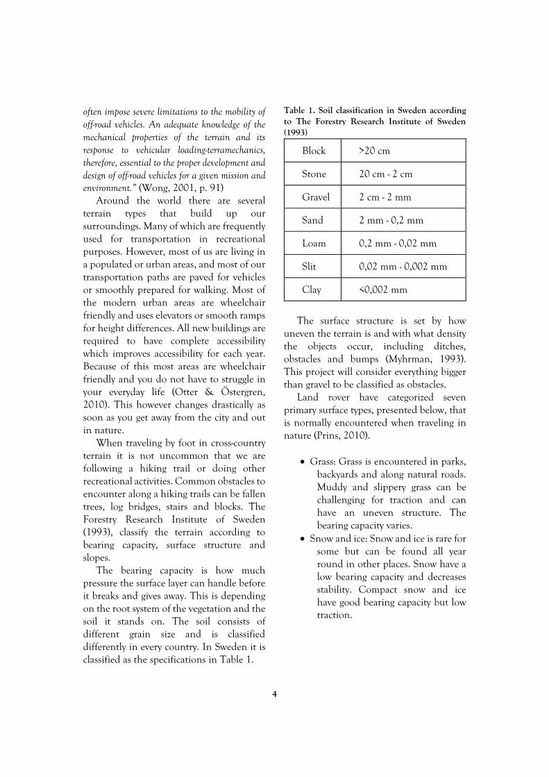
The bearing capacity is how much pressure the surface layer can handle before it breaks and gives away. This is depending on the root system of the vegetation and the soil it stands on. The soil consists of different grain size and is classified differently in every country. In Sweden it is classified as the specifications in Table 1.
Table 1. Soil classification in Sweden according to The Forestry Research Institute of Sweden (1993)
The surface structure is set by how
uneven the terrain is and with what density the objects occur, including ditches, obstacles and bumps (Myhrman, 1993). This project will consider everything bigger than gravel to be classified as obstacles.
Land rover have categorized seven primary surface types, presented below, that is normally encountered when traveling in nature (Prins, 2010).
Grass: Grass is encountered in parks, backyards and along natural roads. Muddy and slippery grass can be challenging for traction and can have an uneven structure. The bearing capacity varies.
Snow and ice: Snow and ice is rare for some but can be found all year round in other places. Snow have a low bearing capacity and decreases stability. Compact snow and ice have good bearing capacity but low traction.
Block >20 cm
Stone 20 cm - 2 cm
Gravel 2 cm - 2 mm
Sand 2 mm - 0,2 mm
Loam 0,2 mm - 0,02 mm
Slit 0,02 mm - 0,002 mm
Clay <0,002 mm

5
Gravel and dirt roads: Roads prepared for hiking or infrequent vehicle traffic. Inconsequent surface structure that can cause high vibrations in various speeds. Loose gravel and stones cause bad traction.
Mud: Bad bearing capacity since the surface layer is broken or non-consistent. Low ground pressure is needed to stay on top or high ground clearance to find traction below. Can be found in all terrain where the surface layer is broken and the ground is wet.
Sand: Commonly found in deserts and on beaches but also along hiking trails. Good bearing capacity when moist but bad when dry. Bad traction due to low internal friction in the soil, especially when dry.
Ruts and boulder crawl: Very rough inconsequent surface structure with big obstacles and gaps. Big step heights with steep slope facets can occur. Normally encountered in parts of hiking trails. Main obstacles are blocks and roots.
Wading: When crossing shallow waters such as small streams and lakes. Encountered along hiking trails but not very frequently.
2.3 Off-road capability Properly defining off-road capability is
not a trivial task. The British car manufacturer Land Rover, who has developed off-road vehicles for over six decades (Smith, 2013), has multiple definitions for off-road capability. Their most elaborative reads:
“Covering the distance from A to B transporting occupants and payload in an acceptable amount of time with a minimum level
of comfort for all occupants not exceeding a maximum level of driver effort and without causing damage to vehicle or terrain.” (Prins, 2010, p. 3).
In 1965 a Standardization Committee was founded and their task was to investigate and determine a list of standardized terms regarding terrain-vehicle locomotion. This standardization includes information about both terrain- and vehicle characteristics (Chumas & Hartman, 1975).
Jo Yung Wong (2001) divides the characteristics of a ground vehicle into three categories; performance, handling and ride.
Performance refers to the vehicles ability to overcome obstacles, accelerate/decelerate and generate drawbar pull (Wong, 2001). Drawbar pull is a measurement of the available tractive force of a vehicle, which essentially measures the maximum lateral force a vehicle is capable of exerting before the traction elements begin to spin due to loss of traction (U.S. Army, 1961).
Wong (2001) describes handling as the vehicles capability of transforming the driver’s input into an expected output while stabilizing the vehicle as a response to external disturbances.
The final category of vehicle ride refers to vehicle vibrations due to surface irregularities (Wong, 2001). Wong continues by stating that: “An understanding of the behavior of the human driver, the characteristics of the vehicle, and the physical and geometric properties of the ground is, therefore, essential to the design and evaluation of ground vehicle systems.” (Wong, 2001, pp. 1-2).
For this project, further investigation into off-road capability has been split into two categories, obstacles and soil, as defined in the previous chapter. This makes it possible to separate influences and key aspects that you need to consider when developing an off-road vehicle.

6
2.3.1 Obstacle capability
It can be argued that a vehicles off-road capability boils down to its traction, if a traction element is not in contact with the ground it will not be able to propel the vehicle forwards. Therefore, it is of utmost importance to keep the traction elements in contact with the ground. In order to measure a vehicles ability to do this a few standardized terms and measurements have been used according to the International Society for Terrain-Vehicle Systems, (ISTVS, 1968).
Figure 1. Angle of approach Angle of approach is the maximum angle between the ground plane and a plane tangent to the foremost traction element and touching the vehicle chassis or body, see
Figure 1 (ISTVS, 1968).
Figure 2. Angle of break
Angle of break refers to the maximum angle between two planes tangent to front and rear traction element respectively intersecting each other and vehicle undercarriage, see Figure 2 (ISTVS, 1968).
Figure 3. Angle of departure
Angle of departure is the maximum angle between the ground plane and a plane tangent to the rearmost traction element and touching the vehicle chassis or body, see Figure 3 (ISTVS, 1968).
Figure 4. Ground clearance
Ground clearance is the vertical measurement between the ground plane and the lowest point on the vehicle undercarriage, see Figure 4 (ISTVS, 1968).

7
Figure 5. Angle of pitch roll and yaw
Angle of pitch is vehicle rotation around
the Y-axis, i.e. in the X-Z plane, as can be seen in Figure 5 (Wismer, 1965).
Angle of roll is vehicle rotation around the X-axis, i.e. in the Y-Z plane, as can be seen in Figure 5 (Wismer, 1965).
Angle of yaw is vehicle rotation around the Z-axis, i.e. in the X-Y plane, as can be seen in Figure 5 (Wismer, 1965).
Figure 6. Slope (lateral) stability
Slope (lateral) stability is the maximum
angle on a ramp that a fully loaded vehicle can traverse perpendicular to the inclination without tipping over, as seen in
Figure 6 (U.S. Army Transportation Combat Developments Agency, 1963).
Ramp Travel Index (RTI) is a way of measuring a vehicles ability to articulate its suspension without losing contact between any of its traction elements and the ground. Since vehicle wheelbase is taken into consideration when calculating the RTI score, it is a good method for a quick and easy comparison of different vehicle’s articulation and overall flex (Ramp Travel Index, n.d.).
2.3.2 Soil capability
Calculating, measuring and predicting a vehicle’s ability to traverse a certain type of soil is a complex issue, below is a few standardized terms and measurements.
Tire tread is something projected on a tire in order to improve propulsion (ISTVS, 1968).
Track ground contact area is the summarized areas of all traction elements that are in contact with the ground surface. Including openings or interruptions because of grousers (U.S. Army Engineer Waterways Experiment Station, CE, 1965).
Track ground contact pressure is the total weight of a vehicle divided by the track contact area (U.S. Army Engineer Waterways Experiment Station, CE, 1965).
Bearing capacity, ultimate is “the average load per unit of area on a footing required to produce failure by rupture of a supporting soil mass (American Society for Testing Materials, 1972)”.
Continuing on the importance of traction, it is not given that a traction element will be able to provide tractive force even though it is in contact with the ground. If the ground, or soil, is loose or slippery the element will not grip on the surface but instead skew the soil or slip on top of it. If encountering loose soil, or soil with low bearing capacity, you basically have two

8
choices; one, design a vehicle with low track ground pressure that traverses on top of the soil. The other way is to design a vehicle with higher track ground pressure that penetrates the soil and instead is able to grip on the firmer soil underneath, if one exists. A typical example of this is snow covered terrain, where the snow often have a lower bearing capacity than the ground underneath (Myhrman, 1993).
2.4 Vehicle dynamics Vehicle dynamics are closely related to
vehicle ride characteristics i.e. how does the vehicle behave and how does it affect the ride quality and therefore passenger comfort. What happens is that surface irregularities, imbalances in the propulsion unit and driveline create vibrations which are transferred through the traction elements into the chassis and eventually reaching the passenger. There are a few terms that are essential to the science about vehicle dynamics, that is sprung mass, unsprung mass, natural frequencies and amplitude ratios, also called transmissibility ratio (Wong, 2001).
Picture a typical car, the main chassis and body are suspended from the ground by springs and dampers that are connected to the wheels. Since the body is suspended on springs, it is called sprung mass. The wheels however are not supported by anything other than their tires, which do work as springs but not in the same order of magnitude, and therefore the wheels and running gear is referred to as unsprung mass (Wong, 2001).
Natural frequency is the frequency at which the system oscillates when not affected by external forces. Oscillation by external forces is called forced frequency, and if the forced frequency is equal to the systems natural frequency, a significant increase in the amplitude of the vibrations
occur which is called resonance (Natural Frequency and Resonance, n.d.). The ratio between natural frequency and forced frequency is called amplitude ratio or transmissibility ratio (Chan, n.d.). As expressed by Jo Yung Wong (2001); “The wide separation of the natural frequencies of the sprung and unsprung mass has a significant implication on the vibration isolation characteristics of the suspension system.” (Wong, 2001, p. 446).
Wong (2001) continues by stating that when evaluating a suspension system in regards to its overall performance, three different aspects should be considered; vibration isolation, suspension travel and road holding.
2.5 Comfort Comfort is a complex definition of a
combination of both physiological and psychological factors. It is not the opposite of, but could be explained by the absence of discomfort, stress and pain (Bohgard, et al., 2008). Both the physiological and psychological factors are to some extent subjective, but can be measured and therefore graded. ISO 2631 (Swedish Standard, 1998) focuses on whole-body vibrations and indicates the factors which makes a vibration exposure acceptable. The vibrations are separated in two ranges, 0,5 Hz to 80 Hz which is for health, comfort and perception while 0,1 Hz to 0,5 Hz is used for estimating motion sickness.
When designing a ground vehicle it is generally a compromise between handling and comfort (Els, Theron, Uys, & Thoresson, 2007), which is why many cars have a so called “sport mode” which stiffens the suspension for better handling. A softer suspension spring will generally provide a better vibration isolation and higher comfort, but will most likely affect the road holding capability (Wong, 2001).

9
Method and Implementation This chapter describes the process used in the project and how each task was implemented
and why. It is presented in the same order as they were performed and all steps contributing to the end result are documented in this section. The methods and processes were formed by the theoretical framework and the context research.
3.1 Process In this project, a method called Pulse
Model was used as the overall process planning tool. Pulse Model is an organizational model that can be used in all areas of an organization. It is an agile model that implements LEAN and focuses on development and delivery. Pulse Model is commonly used in strategy-, market- and product development but also within the production and sales departments. Permobil uses Pulse Model for their product development process, which is why it was chosen as the planning tool for this project. The goal is to create decentralized and self-organizing workgroups within the framework set by the head of operation. By having an interactive visual representation
of the project the progress and problems are easily exposed to increases productivity. This visual representation is called a Synchronization-plan (Parmatur, 2013).
A modified Synchronization-plan was created in order to divide the project goals into sub results and make an overall plan of the project. The synchronization plan included a total of six handover points (HP) and work packages. A simplified visualization of this plan may be seen in Figure 7.
HP 2.5 and preceding work package will not be included in this report since they did not have any impact on the outcome of the project. The remaining work packages and handover points will be handled in more detail in the following chapters.
Figure 7. Synchronization-plan

10
3.2 Project planning This section will describe the methods
used during the initial stages of the project where an overall plan and time schedule was determined.
As described earlier, a Synchronization -plan was created in order to form the outlining structure of the project and the including stages. This plan contains all the tasks that have to be performed in order to succeed with the project and handover points to separate different stages and work packages from each other. The handover points consisted of a set of deliverables needed in order to continue with the next work phase. It provided a good visual representation of what could be done simultaneously and which dependencies there were between the different stages in the project.
For each work package entry, an individual checklist of assignments were made and continuously updated to visualize progress and problems. This also reduced the time needed for administration and planning while the project was being executed.
By making an overall planning of the project and adding expected time duration to each task, the proportion of each work package could be estimated and the handover points determined. This meant that each work package got a deadline and time limit so as not to delay the final due date of the project. Figure 8 shows part of the finished Synchronization-plan which was created on a large white board in the project office to allow for quick overview and updates. Each task was pinned with a colored magnet which represented different progress, green if completed, yellow if work
Figure 8. A modified Synchronization-plan with work package and handover point

11
had begun but was not completed and red if any problems occurred.
3.2.1 Budget
When the project goals, scope and overall planning was complete, a preliminary budget was made with calculated expenses of materials and hours planned.
3.3 Context immersion This section describes the project stage
where the current solutions was evaluated and overall market analysis were performed. The methods used aimed to paint an overall picture of the product context.
3.3.1 Current product
Permobil’s current offering in the market of off-road capable electric wheelchairs, or class C as per ISO 7176-5 (Swedish Standards, 2008), is the Permobil X850 launched in 2008 as a facelift of their discontinued Trax model. The main improvements on the Trax that led to the X850, as shown in Figure 9, was an improved steering mechanism as well as new bodywork.
Figure 9. Permobil X850
The reason behind the change of steering system was because of a large number of expensive warranty replacements of a steering cable. In the X850, this cable has been replaced by an electronic linear actuator mounted directly to the front steering linkage, thus the X850 utilizes a drive-by-wire configuration. 3.3.1.1 Market
A series of unstructured interviews (Bohgard, et al., 2008) were conducted with various staff at Permobil in order to determine current markets, their size and target users. Between September 2014 and February 2015, Permobil sold around 2000 electric wheelchairs of which circa 10% were of the X850 model. The X850 is based on a proprietary chassis and is assembled to order at their main production line in Timrå, Sweden.
Norway is currently the largest customer of the X850, ahead of Sweden. The main difference between these two markets are the rules that govern the distribution of electric wheelchairs. In Norway, users are often given two electric wheelchairs, one for indoor- and one for outdoor use. The ruling organizations in Sweden are less liberal with their distribution and users are generally not given two chairs if it is not deemed necessary. In Sweden there are strict rules that prohibits the distribution of chairs for recreational use. 3.3.1.2 Measurements
In order to quantify its off-road capability, a series of measurements and test drives were performed. The tests performed were inspired by ISO 7176-1 (Swedish Standard , 2015) to be somewhat comparable to competitive products. The test vehicle can be seen in Figure 10.

12
Figure 10. Test vehicle with 136 kg dummy
Some measurements were taken from
Permobil’s internal records from when they performed ISO tests ahead of product launch, such as static and dynamic stability, obstacle climbing ability etc. Added to these were, among others measurements of angle of approach/brake/departure, ground unevenness (Figure 11), and Ramp Travel Index. The full list of measurements can be seen in the product specification found in Appendix A. The measurements from the X850 can be seen in.
Since many of its rivals have performed the before mentioned ISO tests, the measurements in table X above allowed for quick comparisons between the X850 and its competitors. It also proved useful later in the project when specifications for the final concept had to be determined.
Table 2. Measurements of Permobil X850. More information can be found in Appendix A
Metric Permobil
X850
Angle of approach 42°
Angle of break 30°
Angle of departure 63°
Occupant mass <= 136 kg
Dynamic stability Score 3 at 10°
Static stability >17,8°
Maximum speed 10-15 km/h
Obstacle climbing ability 110 mm
Ground unevenness 205 mm
Total length 1450 mm
Total width 730 mm
Turning diameter 4080 mm
Ground clearance 78,8 mm
Ramp travel index (RTI) 453 RTI
Wheelbase 1024 mm
Vehicle mass 193,5 kg
Wading 95 mm
Figure 11. Test of maximum ground unevenness

13
3.3.1.3 Tests In order to get a complete understanding
of the strengths and weaknesses of the X850, a series of test drives were conducted in both indoor and outdoor environments. The initial test drives could only be performed in winter conditions with mostly snow covered terrain. This meant that the end-user interviews had to provide important feedback from non-winter conditions that was later verified in test drives when the snow had melted. All test drives were performed by the authors and consisted of a range of different real-life scenarios. This meant that the drivers had no physical disabilities but were instructed not to use their bodies or legs as support or counterweight when needed. This however could not be guaranteed at all times due to natural human instinct when the fear of tipping over arose but the tests were deemed reliable enough to source subjective feedback on the overall performance of the X850.
Initial feedback from the test runs were
discussed within the team and the main strengths and problem areas of the X850 that could be agreed upon were determined. The main strengths found were:
It handled most ground unevenness reasonably well, as long as it passed under the tires.
The slow motor ramp-up and down at joystick input made it safe and easy to maneuver at both its long and short wheelbase setting, high and low speeds and on slippery surfaces.
The automatic parking brake was convenient during steep inclines.
Figure 12. Top; rear chassis caught on obstacle. Bottom; close up of the problem area
The main faults or problem areas found
were:
Driving across even small side slopes created a fear of tipping over.
Ground clearance was relatively low, and the front of the rear chassis was easily caught on obstacles as can be seen in Figure 12 above.
Overall harsh and bumpy ride comfort.
The tires got easily clogged up with mud and snow.
The slow motor ramp-up and down while not being able to use full acceleration as you steered was sometimes a problem when traversing certain terrain types.
Low track ground contact pressure combined with relatively small tires meant that it would easily dig down and get stuck in loose soil, an

14
example of which can be seen in Figure 13 below.
While the turning radius is adequate from most situations, it required a few iterations to make a U-turn on a normal trail.
There was an unpredictable relationship between the front and rear suspension which made it hard to predict which obstacles could be driven over. The front wheels would easily traverse large objects with minimal effort, but when one of the rear wheels were to climb the same object, the whole seat would begin to tilt with a risk of tipping over.
Figure 13. Top; stuck in snow and bottom; a close up of snow clogged tires
3.3.2 Competitive products
There are a lot of comparable Class C products on the market from several manufacturers. There are multiple competing wheelchairs with varying chassis layout and suspension systems on the market which targets the same customers,
but none that is similar to the X850. Some of the competitors have products similar to traditional electric wheelchairs but with bigger wheels, while others aim for certain users or a specific kind of terrain or environment. Figure 14 shows an example of a comparable product.
Figure 14. An all-terrain wheelchair with maintained indoor capabilities
There have traditionally been a
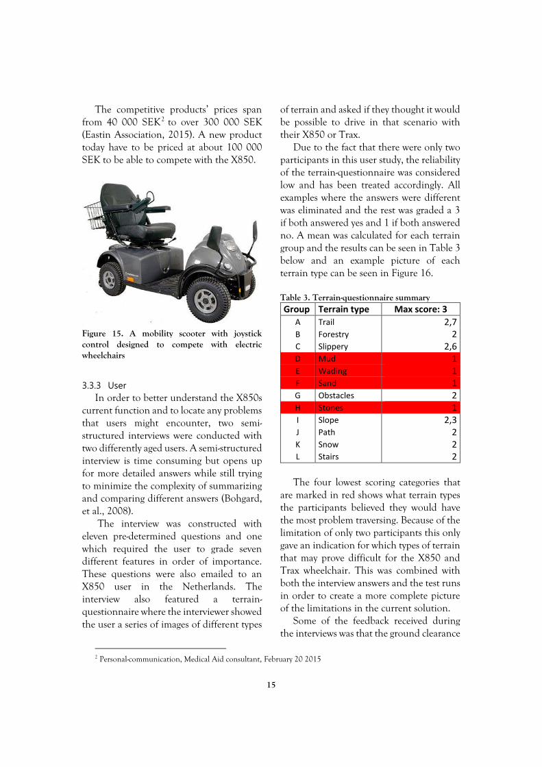
difference between the electric wheelchair and the mobility scooter, but now the line between them is starting to fade as they offer the same features on both platforms, such as seating adjustments and joystick controls. Traditionally the electric wheelchairs are aimed towards users who have very limited ability to move while the scooters have been towards those who can walk shorter distances. This means that the cheaper mobility scooters are beginning to compete with the pricier electric wheelchairs. An example of a mobility scooter can be seen in Figure 15.
15
The competitive products’ prices span from 40 000 SEK2 to over 300 000 SEK (Eastin Association, 2015). A new product today have to be priced at about 100 000 SEK to be able to compete with the X850.
Figure 15. A mobility scooter with joystick control designed to compete with electric wheelchairs
3.3.3 User
In order to better understand the X850s current function and to locate any problems that users might encounter, two semi-structured interviews were conducted with two differently aged users. A semi-structured interview is time consuming but opens up for more detailed answers while still trying to minimize the complexity of summarizing and comparing different answers (Bohgard, et al., 2008).
The interview was constructed with eleven pre-determined questions and one which required the user to grade seven different features in order of importance. These questions were also emailed to an X850 user in the Netherlands. The interview also featured a terrain-questionnaire where the interviewer showed the user a series of images of different types
2 Personal-communication, Medical Aid consultant, February 20 2015
of terrain and asked if they thought it would be possible to drive in that scenario with their X850 or Trax.
Due to the fact that there were only two participants in this user study, the reliability of the terrain-questionnaire was considered low and has been treated accordingly. All examples where the answers were different was eliminated and the rest was graded a 3 if both answered yes and 1 if both answered no. A mean was calculated for each terrain group and the results can be seen in Table 3 below and an example picture of each terrain type can be seen in Figure 16. Table 3. Terrain-questionnaire summary Group Terrain type Max score: 3
A Trail 2,7 B Forestry 2 C Slippery 2,6 D Mud 1 E Wading 1 F Sand 1 G Obstacles 2 H Stones 1 I Slope 2,3 J Path 2 K Snow 2 L Stairs 2
The four lowest scoring categories that
are marked in red shows what terrain types the participants believed they would have the most problem traversing. Because of the limitation of only two participants this only gave an indication for which types of terrain that may prove difficult for the X850 and Trax wheelchair. This was combined with both the interview answers and the test runs in order to create a more complete picture of the limitations in the current solution.
Some of the feedback received during the interviews was that the ground clearance

16
was too low and the motor controllers sometimes overheats in snow, sand or steep inclines3. Its rear tires often get clogged with mud or snow, resulting in the back end either spinning stationary or digging down in the soil4. Furthermore the battery driving range was deemed too short and side slopes are uncomfortable to traverse due to fear of tipping over3. One factor that surfaced in all interviews and tests, was the ride comfort which was deemed too harsh and bumpy3 4.
The results from the user studies were combined with feedback from the test runs performed by the group members to form the basis of two personas.
Erik, 44 years old from Sweden, is a farmer that was paralyzed from the waist down in an accident a few years ago. He still tries to perform many of his old chores at the farm in an X850, with varying success.
Marit, 20 year old and lives in the suburbs of a small city in Norway. Born with a back injury that prevents her from supporting her own body and is therefore in possession of an X850 for outdoor use. She dreams about one day being able to go on a mountain hike together with her friends.
Figure 16. Difficult terrain types. F sand, E wading, D mud and H stones
3 Personal communication, User, February 19 2015 4 Personal communication, User, February 25 2015

17
3.3.4 Customer
The general customer of the X850 and other electric wheelchairs are insurance companies and social security systems. This means that it is not the user that ultimately selects and purchases the product but instead an organization that provides or lend it to the user. The customer wants to fulfill the minimum user needs as cheap as possible. In order for the product to be an available option to the customer, it needs to meet all criteria’s found in both the ISO standards for medical aid ISO 7176 (Swedish Standards, 2008) and social security systems procurement document 5 . Another important aspect is the difference in attitudes towards recreational activities between countries. Norway express a liberal approach to recreational activities, allowing all users access to two wheelchairs each, one for indoor- and one for outdoor use6.Sweden on the other hand does not provide two wheelchairs per user if not deemed necessary, and where recreational interests cannot be used as motivation to receive an outdoor wheelchair5.
3.3.5 The vision of Permobil
Permobil wants everyone to be able to move around as independently as possible regardless of their disability. They want to aim for the users with severe disabilities which requires high quality and customizable solutions, instead of the great quantities that can be found in its cheaper competitors. Since this is a conceptual study, there are no restrictions as long as it follows the Permobil Vision and Mission (Permobil, n.d.).
5 Personal communication, Medical Aid consultant, February 20 2015 6 Personal communication, Permobil sales department, February 24 2015
3.4 Literature review The literature review was performed in
order to source information about Modularity, Terrain types, Off-road capability, Obstacles and Soils, Vehicle dynamics and Comfort. These findings were the foundation on which the rest of the project was based on.
The primary search engine used was PRIMO, a search engine provided by Luleå University of Technology which provides access to a large number of scientific research reports and other published work. Aside from PRIMO, Google.com and books was also used for finding relevant information.
Preliminary research showed that publications were to be found regarding the main topics raised during this project such as off-road capability, vehicle characteristics, vehicle dynamics and terrain characteristics. Aside from the names of these topics, other search terms used were; dirt, mud, sand, gravel, block, terrain, terramechanics, soil, trail, modular design, vehicle dynamics, measuring off-road capability, off-road vehicle. Although publications were available, many were released several decades ago and has mainly been used as industry standards since. Therefore a decision was made to utilize an experimental standpoint based on physical prototypes and experimental tests, while incorporating the industry standards found in literature without relying too heavily on the literature review.

18
3.5 Idea development This stage began with an idea generation
session where the project team first defined a clear problem, which read: “How do you traverse uneven terrain in a land vehicle?”. The session began with solitary idea generation for a set period of time before sharing each the ideas with each other, since this is argued to increase the group productivity (Brown et al. 1998, Hinsz et al. 1997, Nijstad, 2000, Paulus and Yang, 2000 as cited in Perttula, Krause & Sipilä, 2006).
Figure 17. Idea generation using LEGO® Technic bricks.
When the initial batch of ideas had been generated, new inspiration was sought by turning to LEGO® Technic bricks, as can be seen in Figure 17. This enabled prototypes of some of the ideas to be created quickly and effortlessly which could either lead to the idea being dismissed or to it spurring new ideas.
7 Personal communication, User, February 19 2015 8 Personal communication, User, February 25 2015
These primitive prototypes were used to
help visualize and test different linkages and the behavior of a certain suspension system in different situations. One example is the prototype shown in Figure 18, which was inspired by feedback from the user interviews7, 8 which stated that side slopes was a troublesome obstacle in current solutions. The LEGO® prototype shown to the left, with electronically controlled rear
Figure 18. Top; LEGO® prototype of active side slope stability control. Middle; system deactivated. Bottom; system activated.

19
suspension was the result of an iterative process which began with combining some of the initial ideas and then refining and improving the idea based on the result from different stages of LEGO® prototypes.
3.5.1 The catalogue method
The catalogue method, also known as the literature method, is the generic name for reviewing products and solutions that already exists throughout different kinds of media (Johannesson, Persson, & Petterson, 2013). This method was used mainly during the initial ideation process to explore other off-road wheelchairs and vehicles on YouTube and Google images. Later in the ideation process it was used to verify and compare new ideas with the solutions on the current market.
The catalogue method saved a lot of time in the ideation process by giving opportunity to study and review ideas and solutions that already exists or have been implemented by others. This also made it easier to evaluate ideas and compare them to each other. It is important to have an open mind while using this method and remember that there are several ways to implement the same idea.
3.5.2 Function prototype
While many of the ideas could be evaluated through discussion, comparisons with current solutions, determining its pros and cons or even building simple LEGO® prototypes, some required a more hands on approach. The idea of an active side slope stability system, as shown previously in Figure 18 as a LEGO® prototype, was something that was not to be found in any currently available solution. The idea aims to eliminate a psychological effect that was both mentioned in user interviews9, 10 and
9 Personal communication, User, February 19 2015 10 Personal communication, User, February 25 2015
found during experimental tests, the fear of tipping over. A full scale prototype had to be fabricated and tested in order to better understand the impacts that the system had on the psychological effect.
Figure 19. Full scale prototype with active side slope stability control
A simple full scale function prototype, seen in Figure 19, was fabricated and tested on a custom built ramp, seen in Figure 20, and with regular indoor driving. The stability test was performed by driving the prototype slowly up the ramp while manually compensating the actuators to keep the seat horizontally. The psychological effects were then recorded from the test driver’s subjective feedback and compared to tests without the use of the

20
compensation system. The drivers did not have any physical disabilities and were instructed not to use their legs or body as support or counterweight. The main feedback received from the full scale prototype tests were:
A lower spring rate than the current X850 provided a much softer ride quality, but there was noticeable increase in vehicle roll during high speed cornering compared to the stiffer X850.
The rear caster wheel setup on the prototype performed poorly in regards to stability, obstacle climbing ability and steering due to it not being controlled and therefore is highly influenced by external forces.
The active suspension system provides a significant increase in side slope stability, both
experienced and measured. The prototype system was able to level the chassis when traversing a side slope of up to 20°, which in the controlled tests was simulated by applying a ground unevenness along one side of 145 mm, as can be seen in Figure 21.
3.6 Idea evaluation and concept creation
Two methods were used when putting the batch of ideas through an initial screening process. Scrap or Save is a self-invented method which is a quick idea elimination method, while pros and cons is a generally known method for decision-making. First out was the Scrap or Save method, where each idea was subject to a few minutes of general discussion and evaluation, after which a decision had to be made if it should be scrapped or saved for further development. This method made it easy to relatively quickly reduce the amount of ideas on the table. After, Pros and cons was
Figure 20. Top; test on a ramp and bottom; close up of active actuator system Figure 21. Top and bottom; close up of test

21
used to highlight each ideas’ positive and negative attributes. This made it possible to eliminate a few more ideas, which left a total of seven different suspension systems as well as a few steering layouts and general ideas. Both the steering layouts and general ideas were put aside as the suspension systems was put through further evaluation with the aid of an evaluation matrix (Ulrich & Eppinger, 2012).
The weighting factors included in the matrix was divided under four topics; handling, space demand, complexity and flexibility. Handling included factors such as if the suspension system would generate a change in camber or caster during travel, or if the geometry creates a positive or negative torque around the main suspension arm when it hits a 90 degree wall. Space demand estimated how much volume the suspension system would need and in which direction. Complexity evaluated how many parts and joints that were needed, how complex they are and an estimation of their durability. The final topic, flexibility, aimed to compare how future proof the different systems were by evaluating the possibilities of mounting different types of motors and steering mechanisms to the system.
The resulting weighted matrix, which can be seen in Appendix B, shows that the top scoring suspension system for both front and rear position was the trailing arms. It was therefore decided that one of the concepts should feature trailing arms both front and rear, as can be seen in Figure 22. Two more concepts was selected as a result from both the matrix, judgement and discussions. The first of which had a sub frame-based suspension system both front and rear, as can be seen in Figure 23. The last concept featured a McPherson suspension in the front and four-link in the rear, as can be seen in Figure 24.
The three concepts, together with the X850, formed the basis of the forthcoming concept development phase which aimed to more closely examine and evaluate the concepts to create one final concept.
Figure 22. Concept 1: Trailing arm front and rear
Figure 23. Concept 2: Sub frame front and rear
Figure 24. Concept 3: McPherson in the front and four-link in the rear

22
3.7 Concept evaluation As described in the previous section,
three main concepts were created for further evaluation. This section will describe the process of examining and evaluating them in order to create concept alpha, which would later be developed into the final concept.
This process began with discussing the positives and negatives of each concept, comparing their possibilities and limitations. The first concept to be questioned was number three, seen in Figure 24, which featured McPherson suspension in the front and four-link in the rear. It was concluded that the concept did not bring any significant improvements over concepts one and two that could defend its increase in complexity. This is further proven in the weighted matrix as shown previously in Appendix B. Concept three was therefore discarded, and work began to evaluate and examine concepts one and two.
Maintaining a low center of gravity is of importance in order to achieve good stability, therefore the seat and footrest need to be mounted as low as possible. This requires available space between the front wheels for the footrest. Concept two, with a sub frame construction did not allow for a low mounted footrest, which led to the elimination of sub frame as a front suspension. However, the idea behind the sub frame, with dependent wheels capable of traversing large objects with equal weight distribution between the wheels, was something worth investigating further. That train of thought led to the idea of a trailing arm suspension interconnected with a linkage. Due to large forces acting on the linkage, it was not possible at this stage to incorporate any form of active roll or pitch compensation system, it was therefore decided to move any active system to the
rear suspension. In order to be able to maneuver the wheelchair around large obstacles or in narrow spaces, the different concept´s steering abilities were examined. Test drives were conducted which compared the current X850 against a typical electric wheelchair with pivot wheels and differential steering, which basically means that it can pivot around its own axis by driving the wheels in opposite directions. It was concluded that while differential steering is easier to operate in tight conditions, they are not suited for loose soil or slippery surfaces unless the pivot wheels are controlled by a servo. The traditional front pitman steering on the X850 provides good stability and maneuvering capabilities on most surface types and vehicular speeds. It is however less capable when maneuvering narrow tracks and spaces, especially indoors. It was deemed necessary to be able to turn the steered wheels 360 degrees in order to minimize the turning diameter. Combined with the requirements for the overall vehicle footprint, this eliminated any actively steered front wheels and sub frame as rear suspension.
In summary, concept one with front and rear trailing arm was chosen to be the design that had the most potential and that best corresponded to the project goals and product specification. However the basic function and idea of the sub frame concept was implemented on the front trailing arm suspension, while the rear included an active roll- and pitch compensation system.
In order to evaluate the chosen concept it was decided that a full scale prototype had to be designed, fabricated and tested. This will be presented in the next chapter.

23
3.8 Method discussion The synchronous-plan made in the beginning of the project proved useful and stayed accurate until the very end, when project priorities were set more accurately and the time needed to fulfill the deliverables was estimated. Due to the visual layout of the synchronous-plan, it was easy to implement, understand and update to reflect changes in project planning.
Even though the initial assignment, as presented in section 1.4, was relatively vague, the requirements quickly ramped up during the initial stages of the project as the demands of both the customer, user and Permobil became clear. The methods used to determine the capability of the X850 proved to be both useful and accurate when later validating the data collected from the interviews with tests. The use of LEGO® in the ideation and concept stage was very effective and made it easier to test and explain different ideas to each other. Fabricating a prototype and being able to test it side by side with a current product raised the reliability of the comparison between the final result and current X850 as opposed to a comparison between their tables of specifications. It is however more difficult to make any assumptions regarding validity, or the comparison between those two and the rest of the market, since they were the only models available for testing.
An important aspect that needs to be raised, especially since the process used relied heavily on experimental tests, is the aspect of the test drivers, and specifically their physical abilities. During interviews with staff at Permobil, it became clear that the general opinion of the X850 was that its off-road capabilities were very good, more so than one would imagine after a quick glance at its specifications.
When test drives were conducted, it was concluded that the staff at Permobil had a point, it really did outperform its specifications. But then we need to take into account the fact that all these opinions came from drivers who are not suffering from any physical disabilities, but are perfectly capable of counteracting a tipping chair with the strength and weight of their upper body, or stepping out of the wheelchair if it gets stuck to give it a push. All this means that they are more comfortable in taking a wheelchair to its absolute limit, since they know that they will not be in any severe danger if anything goes wrong.
Put that into perspective by imagining what it would be like to drive a wheelchair if you are not in control of any muscle below your chest, or do not have any strength in your legs. It does not seem that far-fetched to believe that a user with those kinds of physical disabilities would be more careful when driving a wheelchair, especially if they are alone with no one close by to assist if they get stuck or fall over.
This aspect presents a dilemma regarding the projected level of off-road capability, which may be explained as the roughness of terrain that the user believes, or feels comfortable traversing. Due to the reasons discussed above, it could be argued that this projected level of off-road capability will be less than the maximum off-road capability that the vehicle is capable of when operated by a physically fit human being.
Since the test drives were conducted with drivers that do not suffer from any physical disabilities, it is important to clarify that many of the specifications presented should be viewed as the maximum off-road capability, that the projected capability, that the end user will safely be able to experience, will be less.

24
Although this report only includes the methods and theories that directly contributed to the end result, a lot of time in the ideation and concept evaluation process were spent on simulating different suspension system combinations. Only to later determine that as long as the spring and damping characteristics is set according to the systems specifications. The only things needed to be considered about the suspension system was if there were enough allowance to implement the desired movements, keep the unsprung mass low, and make sure it was rigid enough to be tested. Not much time had to be spent fabricating because of the extensive use of off-the-shelf parts which reduces the time needed to fabricate specialized parts. This confirms the benefits described in the section 2.1 about modularity and how it can increase efficiency.
The Terrain questionnaire used in the interviews was helpful later in the project. With the terrain questionnaire photos as a reference, similar terrain could be found and tests be performed with the X850, and later the prototype, to be able to determine if the prototype performed better than the X850 and if the X850 actually had the difficulty their users was experiencing.

25
Result and discussion The goal of this project was to develop a concept for a new off-road electric wheelchair
chassis to ground interface. This chapter presents the final concept and describes the key aspects to it.
Figure 25. CAD assembly of concept alpha
4.1 Concept prototype It proved difficult to fully understand the
implications and performance of all the systems and features that were included in concept alpha, so to further evaluate these it was decided that a full-scale proof-of-concept prototype was to be fabricated. The prototype aimed to examine the feasibility of different variations of concept alpha, in order to select the specifications for the final concept.
Figure 25 shows the CAD assembly of the prototype as seen from the front left corner. The large flat sheet metal on top of the assembly is the seat elevator, which can be used to raise or lower the seat according to user input. This elevator is a current solution by Permobil and has been incorporated in this prototype as it is, even though it was 100 mm higher than necessary. This resulted in a slightly higher location of the center of gravity than desired, but designing a new seat mount was

26
not part of the project scope and the implications of higher center of gravity were therefore accepted.
4.1.1 Front suspension
Figure 26. Isolated front suspension
In Figure 26, only the front suspension (colored) is visible on the chassis. The blue pivot bar connects the left and right (red and green respectively) trailing arm via the two shock absorbers. When in use, this system is able to cope with large differences in the terrain while still spreading out the frontal load 50% on each wheel.
Figure 27, front suspension demonstrating the pivot bar function
Figure 27 demonstrates how the parts interact while compensating a 200 mm obstacle under the right tyre (green arm). The lime green cylinders located under the blue pivot bar are rubber end stops which will deform. The different heights and mounting locations were designed so that different configurations of rubber bushing sizes and hardness could be put to test.
Figure 28. Close up of front pivot bar locking mechanism
Figure 28 is a close up on the blue pivot
bar specifically the incorporated locking mechanism. The black knobs were spring loaded and pushed a pin into the steel slot (green) or rubber bushing (pink) respectively. If the knobs were pulled out and turned 90 degrees they lock the pin outside of the slot and bushing, allowing the blue pivot bar to rotate freely. This locking mechanism allowed three different configurations to be tested.
1. Both pins in free position allowing pivot bar movement as shown in Figure 27.
2. Only the outer pin locked inside the rubber bushing (pink) which allows some rotational movement of the pivot bar.
3. Only the inner pin locked inside the steel slot (green) which will completely lock all rotation of the blue pivot bar.

27
The first configuration was supposed to prove itself useful in very rough terrain with obstacles up to 200 mm tall, the second was aimed to be used in intermediate terrain where the vehicle could be traveling at medium to high speeds. The third configuration looked to stabilize the suspension when traveling at the highest speeds on a very smooth surface that only requires the amount of travel that the shock absorbers can handle.
4.1.2 Rear suspension
Figure 29. Isolated rear suspension
Figure 29 shows the chassis with only the
rear suspension mounted. It consisted of a pushrod lever (purple), an electronic linear actuator (blue), a mounting plate (orange), rear trailing arm (brown) and a fork (green). This setup enabled the ride height to be electronically adjusted ±100mm on each wheel individually while maintaining full travel of the shock absorber for all heights. In Figure 30 is a series of images showcasing the left rear trailing arm in its normal position (top), fully raised wheel position (middle) and fully lowered wheel position (bottom).
The rear suspension was designed in such a way that it allows for either a servo controlled ±30 degree steering action, or passive 360 degree steering by removing the black steering servo actuator. When using the passive steering, the actual steering is
controlled by the two front wheels rotating at different directions and/or speeds. The concept was meant to have full active servo controlled 360 degree steering, but on the prototype, the solution described above was decided to be adequate for the test that would be performed. The design of the prototype was validated with the aid of FE-models and hand calculations in order to verify that it would endure the intended tests.
Figure 30. Active roll- and pitch compensation system in three different states
Normal
Raised
Lowered

28
4.1.3 Prototype testing and evaluation
Two prototypes was built and evaluated. One was built to demonstrate the maneuverability indoors while the second one was built to demonstrate the off road capability in different terrain. The combined abilities of the prototypes can be found in Table 4 and a comparison with the X850 in Appendix A.
Table 4. Measurements of the prototypes, more information can be found in Appendix A
Metric Prototype
Angle of approach 90°
Angle of break 52°
Angle of departure 80°
Occupant mass 85 kg*
Dynamic stability NA
Static stability NA
Maximum speed 15 km/h
Obstacle climbing ability 220 mm
Ground unevenness Front Ground unevenness Rear Ground unevenness Rear*
345 mm 215 mm 470 mm
Total length 1370 mm
Total width 740 mm
Turning diameter 1820
Ground clearance 200 mm
Ramp travel index (RTI) 1091,7
Wheelbase 924mm
Vehicle mass 230 kg
Wading 200 mm
The indoor prototype used front wheel
steering while the rear wheels was free to rotate 360 degrees. It was built to test the maneuverability of the concept in an indoor environment and to determine how much space that would be required to navigate the
slightly longer prototype with a wheelbase of 924 mm and an overall length of 1370 mm. This can be compared to the X850 which had an overall length of 1450. Due to not optimized caster wheels in the prototype, the responsiveness of the steering was unsatisfactory but still enough to demonstrate the space needed for a u-turn and similar maneuvers. The prototype had a turning diameter of 1820 mm compared to 4080 mm of the X850. This showed that even though the concept was longer than X850 it is still more convenient to use indoors.
The front wheel steering did not work well together with the front pivot bar and the softer suspension and tended to tilt the chair instead of rotating it. This was most likely caused by the unfavorable rear wheel caster and offset construction which prevented them from following smoothly.
The outdoor Prototype was tested in various terrain with a test driver of approximately 85 kg and a weight of the prototype of about 230 kg compared to 196 kg of the X850. The control system used was not optimized for four wheel drive which made the tires skid while steering. Due to the simple control system used in the prototype the steering did not have the correct angles which added to the effect. Despite that, the maneuverability was good enough to be able to conduct the intended tests. Due to not optimized control systems the efficiency of the vehicle was lower and with four motors instead of two the battery time was shorter on the prototype than on the X850.

29
Figure 31. Turning sequence of the prototype (right) compared to the X850 (left)
The forward seat position and higher
location of gravity contributed to decreased stability caused by the front pivot bar and had to be locked in the rubber bushings to tilt to the left or right. With the added resistance for the rotation of the pivot bar the prototype behaved well in rough terrain but had problems with slope (lateral) stability, most noticeable when going downhill diagonally. Because of this the prototype did not have the dynamic or static stability desired.
The tests were performed on similar terrain as the terrain questionnaire used in the survey described in section 3.3.1, and the X850 was simultaneously tested in order to be able to compare it to the prototype. This enhanced the reliability of the tests and gave direct feedback of how the prototype was performing compared to the current solution. Snow and ice was not part of this comparison since it was performed in May and no snow was present.
The tests showed that the prototype was capable of traversing different types of
terrain and performed better than the X850 on all of the tested off-road terrain and surfaces. With a ground clearance under the chassis of 200 mm, it ran over stones and other obstacles found on the paths without getting stuck and with an angle of break of 52 degrees it was able go over any bump without getting stuck on the chassis. This was a major improvement compared to the X850 which got stuck several times on the chassis. The angle of approach of 90 degrees on the prototype proved to be very useful, for instance when crossing small ditches where the X850 would get the front buried and not being able to continue. The angle of departure of 80 degrees also proved valuable for the same reasons. With at least 200 mm from the ground to closest electrical component, the prototype was able to traverse water puddles twice as deep as the X850. The obstacle climbing ability was twice as high on the prototype as on the X850 which was really noticeable in rough terrain when crossing fallen trees and branches, as seen in Figure 32.

30
Figure 32. The prototype crossing a fallen tree
The tires that proved to perform poorly
in the initial tests of the X850, as described in section 3.3.1 was also used on the prototype. By using the same tires, the comparison had higher validity since the construction of the chassis was the only difference. The tires performed well and did not clog like they did on the X850. This was because the force needed to move the vehicle with four wheel drive did not exceed the internal friction of the soil which kept it from skewing. The benefit of four wheel drive showed to be even more valuable since the total weight of the prototype was higher than the X850. Since the prototype had bigger front tires, the track contact pressure was estimated to be about the same as the X850. This meant that the original tires used for the X850 can be used if it is four wheel drive to be able to traverse terrain while also creating a comfortable quiet ride at the speed of 15 km/h on pavement.
The comfort of the prototype was a lot better compared to the X850. The footrest was attached to the chair which makes it independent from the front wheel and the users seating position did not change regardless of suspension travel or steering.
The user could also from a standing position sit down in the chair without having to climb up on the footrest or turn the seat around as needed on the X850. The suspension on the prototype allowed for much more travel which made the ride less bumpy and the ascending and descending of curbs less harsh on the user.
The outdoor prototype was equipped with an active roll and pitch compensation system that would automatically adjust the chassis of the prototype to be in a horizontal position. This increased the stability of the chair and enabled it to compensate and stay horizontal in side slopes that would otherwise cause it to tip over. This was not used on the outside test mentioned earlier due to software issues but would probably have increased the stability and reduced the tendencies to tip over that was discovered. The compensation system allowed the prototype to traverse obstacles of 10 cm without tilting the chair and height differences between the rear tires of 200 mm.

31
The Ramp travel index on the prototype was high with a value of 1092 compared to the X850 that had 453. This was noticeable during the tests where the prototype managed to have all wheels on the ground under almost every condition tested. The prototype was able to tackle ground unevenness up to 345 mm while the X850 would lose ground contact at 205 mm. With the active compensation activated the prototype could handle a ground unevenness of up to 470mm.
The prototype proved durable enough to endure the tests performed and there were no mechanical breakdowns. The least rigid component was the rear arm and fork construction, which did flex noticeable, but resisted deformation. Because of the simple construction of the prototype it should be relatively easy to reinforce the rear arm construction and therefore reduce the flexing considerably. The tests were conducted with an 85 kg driver. Except for the rear arms, the concept felt rigid and there were no obvious weak points found that could be a deal breaker to the concept as a whole.
4.2 Prototype evaluation When the tests had been executed, the
observations made were discussed and examined in order to determine what features and abilities that should be included in the final concept. This section presents these observations, which is mainly based on side by side comparison tests with the X850 performed in various environments as well subjective feedback from test drivers on aspects such as ride quality and handling.
4.2.1 Stability
The main concern about the prototype was that it was unstable and could easily tip over when traversing perpendicular to a
downhill slope. This was estimated to be due to bad configuration of the front suspension.
The pivot bar in the unlocked position allowed too much wheel travel which made the vehicle unstable, both when turning and going down a side slope. This should be prevented by shortening the allowed travel of the front pivot bar and making it spring loaded. This should increase the vehicles’ lateral stability and also help the vehicle to regain horizontal position after traversing an obstacle. A side effect of this would be a slightly lower ramp travel index.
When the Pivot bar was in the locked positon during the tests it was still unstable. This was most likely due to soft springs in the front suspension and that the pivot bar still could rotate due to the soft rubber bushings. This issue could be solved by adding harder springs in the front suspension and making sure the pivot cannot rotate in its locked position.
4.2.2 Steering
The steering of the outdoor prototype worked really well and it did not feel unnatural to maneuver with the rear wheels. The change in caster angles depending on suspension travel and compensation was not noticeable when handling the vehicle and the vehicle felt robust and safe to use. The limited steering on the outdoor prototype did not feel restricted and it was easy to control when traversing uneven terrain, but just as the X850 it requires a few iterations to make a U-turn on a narrow path. It is possible that the steering joystick would be too sensitive if it allowed the wheels to turn 360 degrees that proved to be very useful in indoor environments. A solution to this could be to have a two mode joystick. However this lies outside of the scope of this project.

32
4.2.3 Propulsion
The four wheel drive system proved to be of great value and was probably an important factor for the prototype working well. Although when going up very steep hills the front wheels lost traction due to the weight moving towards the rear wheels increasing the power demand from the rear motors. The same problem can occur on the front wheels in other situations. This problem could be solved with a more sophisticated motor control system that distributes energy to the motors that needs
it the most or by using more powerful motors in the rear, if uphill climbing is prioritized.
4.3 Final Result The final concept, which can be seen in
Figure 33, is an all-round electric wheelchair designed to safely traverse rough terrain while still maintaining high speed stability on the road and easy maneuvering in tight spaces. This section aims to present the key aspects and specifications which forms the final concept, with a focus on the vehicle-to-ground interface.
Figure 33. A rendering of how the final concept can be implemented in a complete solution

33
Figure 34. Ground clearance of the final concept
The most important aspect of the
vehicle-to-ground interface of an off-road wheelchair is ground clearance, illustrated in Figure 33. If it has too low ground clearance it will more easily get caught on obstacles instead of traveling over them. In order to successfully traverse objects up to 200 mm tall, the ground clearance should be at least 200 mm (Myhrman, 1993), which has been validated through experimental tests.
Figure 35. Four wheel drive
Four wheel drive, as seen in Figure 35,
was concluded to be the second most important aspect of an off-road wheelchair. By letting all four wheels create forward propulsion, neither of the wheels are trying to hinder that forward motion as is the case with two wheel drive. This is especially
important when traversing loose soil such as sand and mud or when climbing over obstacles such as fallen trees or loose stones (Myhrman, 1993). It also allows all four wheels to act as brakes which increases the wheelchairs ability to slowly descend a steep slope and reduces its overall stopping distance. By choosing motors with different power output in the front and rear, it is possible to alter the available space needed and the chairs driving characteristics. For example when driving uphill, a torque bias towards the rear wheels is preferred as a weight shift occurs towards the rear wheels. This weight shift results in a loss of traction under the front wheels and increase in traction under the rear wheels as discussed previously in the experimental tests. Another positive aspect of four wheel drive is the ability to use tires that are less optimal for off-road traction. Tires that has less thread, but instead increased efficiency and comfort, as presented by (Wong, 2001), is compensated by the fact that there are four traction elements creating tractive force, as discussed by (Myhrman, 1993).
Figure 36. Weight distribution
The weight distribution should be kept
as close as possible to what is called a 50/50 ratio, which means that 50% of the total weight including driver should be located

34
on the front wheels and 50% on the rear wheels. This spreads the bearing capacity evenly on all four wheels, which minimizes the risk of a wheel sinking into the soil (Myhrman, 1993). It also provides the overall most stable vehicle regardless of its direction of travel and ground slope (ISTVS, 1968), (Myhrman, 1993). See Figure 36 for illustration.
Figure 37. Back wheel steering
By utilizing servo controlled rear pivot
wheels that can be turned 360 degrees, as illustrated in Figure 37, the turning diameter can be kept to a minimum which allows for easy maneuvering in tight spaces. This is also shown in section 4.1.3.
Figure 38. Front suspension
The front suspension should consists of
trailing arms which is a simple construction with minimal amounts of parts and joints. See Figure 38 for illustration.
The left and right wheel also stays at constant distance from each other if seen from above which maximizes the space available for foot rests. A pivot bar system, as described earlier in section 4.2.1 should be used to increase the amount of available wheel travel up to ±50 mm at low speeds in very uneven terrain. Two shock absorbers should provide about 50 mm independent suspension travel at both low and high speeds. The pivot bar should be electronically controllable and have two modes, locked and open. When locked, the bar is not able to pivot and therefore the extra wheel travel is disabled, producing a more stable ride. The open mode enable the bar to pivot in each direction, moving the upper shock absorber mounts relative to each other and thereby allowing greater wheel articulation during low speeds. When open, it should be spring loaded with a force large enough to center the pivot when standing still on level ground. The shock absorbers springs should be stiffer than the one that centers the pivot bar, and otherwise specified in accordance to the vehicles natural frequency as presented by (Wong, 2001).
Figure 39. Rear suspension
The rear suspension illustrated in Figure
39, should also feature trailing arms. As they

35
need to provide space for the wheels to turn 360 degrees, they are mounted to the wheels via caster forks. Due to the fact that the rear wheels are servo controlled, the change in caster angle that they are subjected to during suspension travel does not have any significant negative effect on performance as discovered in 4.2.2. The rear suspension should also feature an optional active roll and pitch compensation system which is able to level the chair while driving. The full effects of this system has not been validated but should be considered when designing an off-road wheelchair. The rear shock absorbers and springs should be specified in the same manner as the front suspension and allow for an equal amount of travel.
4.4 Relevance
The project have shown that it is possible to make a relatively compact and capable off-road wheelchair that makes it possible for almost anyone regardless of disability to explore nature by themselves. The feeling of independence and ability to explore places outside the paved sidewalks are something many wheelchair users desire and can increase the life quality and equality drastically.
Permobil have the opportunity to continue the development with the guidelines presented in the result, which could potentially lay the foundation for their future replacement of the current X850. The project also proves that it is possible to an off-road wheelchair based on their modular chassis.
4.5 Sustainability The concept is heavily based on
modularity, utilizing Permobil’s modular chassis, their current wheel, motor, seat and shock absorber offerings. This could probably be explored even further to reduce the number of unique parts needed and
therefore minimize the impact on workload for the production unit, since they would only need to keep a few additional parts on shelf instead of a complete chassis as with the current X850.
4.6 Future recommendations The suspension system should be
optimized according to the characteristics desired and be optimized with both spring rate and damping effect in mind. This was not done in this project since it requires the unsprung and sprung mass to be set, and have to be calculated depending on how the final vehicle is designed.
An active compensation system deserves a project of its own and should be investigated further. It is a solution that tackles a problem discovered both from current users and by tests. Because of the width limitation of the vehicle to be able to navigate indoors, something has to be added to be able to tackle slopes and inclines in outdoor environments.
Since the wheelchair will be used in more dangerous environments than most, a study should be performed that looks to determine if there needs to be any maximum level of allowed user disability.

36
Conclusion This chapter will answer the research questions set in the beginning of the project and
summarize the final result. This project demonstrates that it is fully
possible to design an off-road electric wheelchair which enables people with disabilities to move around more freely and independently in tough terrain. It also proves that it is possible to do so on Permobil’s new modular chassis, which will reduce both manufacturing, stock and production costs for the products overall life cycle. The research questions was set early in the project and was used as guidance in the early stages of the theoretical framework.
How can a vehicle’s ability to transport a user over natural and unsurfaced terrain be objectively measured and analyzed?
There are several variables that can be measured on a vehicle to determine the ability to traverse unsurfaced and natural terrain. Standards and definitions has been decided upon the subject over the years which pinpoint the critical areas and parameters to consider. This is described in section 2.3 but can be summarized as: All the traction elements should be on the ground with equal ground pressure, regardless of how rough the terrain is, with a ground clearance high enough to not get stuck on obstacles and with all traction elements creating propulsion.
How can different types of terrain be objectively measured and analyzed?
Each country have their own way of sorting and categorizing terrain. Since this project was performed in Sweden the classification set by The Forestry Research Institute of Sweden (1993) was followed with the addition of a few more generally known definitions and categorizations as described in more detail in section 2.2.
How does the vehicle-to-ground interface affect the traction of the vehicle and the comfort of the user?
With a suspension system that always keep the traction elements on the ground with an even weight distribution and propulsion, the right conditions for good traction can be met. When that is fulfilled it will be up to the traction element to make the best of it by having the right tire thread and dimensions. With a soft suspension system you also get the comfort, since the ride will be smoother. But as a tradeoff you will decrease the stability and handling which could make the vehicle unsuitable for other situations such as high speed cornering (Wong, 2001).

37
References American Society for Testing Materials. (1972). Annual Book of ASTM Standards, Part II,
Bituminous Materials for Highway Construction Waterproofing, and Roofing; Soils, Peats, Mosses, and Humus; Soil Resistance.
Bohgard, M., Karlsson, S., Lovén, E., Mikaelsson, L.-Å., Mårtensson, L., Osvalder, A.-L., . . . Ulfvengren, P. (2008). Arbete och teknik på människans villkor. Stockholm: Prevent.
Chan, D. A. (n.d.). Transmissibility. Retrieved February 6, 2015, from BST2522 Building Environmental Science 2 course: http://personal.cityu.edu.hk/~bsapplec/transmis3.htm
Chumas, S. J., & Hartman, J. E. (1975). Directory of United States standardization activities, NBS special publication 417. Washington D.C.: National bureau of standards.
Eastin Association. (2015, 04 29). Details - Assistive Products. Retrieved from European Assistive Technology Information Network: http://www.eastin.eu/en-gb/searches/products/detail/database-rehadat/id-IW_122306.109
Els, P., Theron, N., Uys, P., & Thoresson, M. (2007). The ride comfort vs. handling compromise for off-road vehicles. Journal of Terramechanics, 44, 303-317.
Erixon, G., Erlandsson, A., von Yxkull, A., & Mo Östgren, B. (1994). Modulindela Produkten - halverade ledtider och offensiv marknadsorientering. Stockholm: Förlags AB Industrilitteratur.
ISTVS. (1968). Glossary of terrain-vehicle terms. Journal of Terramechanics, 5(2), 53-69. Johannesson, H., Persson, J.-G., & Petterson, D. (2013). Produktutveckling: Effektiva metoder
för konstruktion och design (2 ed.). Stockholm: Liber. Myhrman, D. (1993). Terrängmaskinen. D. 1. Uppsala: Skogforsk. Natural Frequency and Resonance. (n.d.). Retrieved February 6, 2015, from CPO Science:
http://www.cpo.com/ipcres/pdfs/unit4/ch12sec3.pdf Office of the Chief of Research and Development, U.S. Army. (1961). Proposed dictionary
of ground mobility terms; Report on Third Conference. Tripartite Working Group on Ground Mobility, (pp. B1-B11). Washington D.C.
Otter, A., & Östergren, E. (2010). Stockholm - Staden för alla. Stockholm: Trafikkontoret. Parmatur. (2013). Pulseguide edition 5.2. Stockholm. Permobil. (n.d.). About us: Permobil. Retrieved February 23, 2015, from Permobil:
http://countries.permobil.com/Permobil-Export/About-us/ Perttula, M., Krause, C., & Sipilä, P. (2006). Does idea exchange promote productivity in
design idea generation? CoDesign, 3, pp. 125-138. Prins, I. J. (2010, June 23). Off-Road capability Leadership in the 21st Century. Vehicle
Dynamics Expo 2010 Open Technology Forum. Gaydon, England. Ramp Travel Index. (n.d.). Retrieved February 3, 2015, from Offroaders:
http://www.offroaders.com/info/tech-corner/rti.htm Smith, N. (2013). Land Rover Series I - Classic Project. Engineering & Technology, 8(5), p.
100. Swedish Standard Institute. (1998). SS-ISO 2631-1 Vibration and shock - Evaluation of human

38
sposure to while-body vibration - Part 1: General requirements. Stockholm: SIS. Swedish Standard Institute. (2015). SS-ISO 7176-1 Rullstolar - Del 1: Bestämning av statisk
stabilitet. Stockholm: SIS. Swedish Standards Institute. (2008). SS-ISO 7176-5 Del 5: Rullstolar - Bestämning av yttermått,
vikt och manöverutrymme. Stockholm: SIS. U.S. Army Engineer Waterways Experiment Station, CE. (1965). Performance of Soils Under
Tire Loads, Test Facilities and Techniques. Vicksburg, Mississippi. U.S. Army Transportation Combat Developments Agency. (1963, February). Logistical
Vehicle Off-Road Mobility, Final Report TCCD 62-5. Virginia. Ulrich, K. T., & Eppinger, S. D. (2012). Product Design and Development (5th ed.). New
York: McGraw-Hill. Wismer, R. D. (1965). Identification of Design Parameters for the Off-Road Mobility
Problem. Presented at ISTVS Meeting at Houghton, Michigan. Wong, J. Y. (2001). Theory of Ground Vehicles (3rd ed.). New York: John Wiley & Sons, Inc.

Appendix A – Product Specification (1/1)
Product specification
Appendix A (1/1) Product specification
Appendix A – Product Specification
# Metric Unit ISO 7176 Class B
ISO 7176 Class C
Permobil X850 TS TP-2 Long Wheelbase (136 kg) Prototype Note/Comment
1 Angle of approach ° 42° 90° ISO 7176.
2 Angle of break ° 30° 52° ISO 7176.
3 Angle of departure ° 63° 80° ISO 7176.
4 Occupant mass kg <= 136 kg 85 kg* * Weight of test person
5 Dynamic stability ° >= 6° >= 10° Score 3 at 10° ISO 7176-2:2001 with mod SS-EN 12184:2014
7 Static stability ° 9° 15° >17,8° ISO 7176-1:1999
8 Maximum speed km/h 15 km/h 15 km/h 10-15 km/h 15 km/h ISO 7176-6:2001
9 Obstacle climbing ability
mm 50 mm 100 mm 110 mm 220 mm ISO 7176-10:2008
10 Ground unevenness mm 30 mm 50 mm 205 mm* 190** 215 mm* 345**
470 mm*** SS-EN 12184:2014 8.1.3 *rear wheel **Front wheel ***rear wheel compensated
11 Total length mm < 1400 mm 1450 mm 1370 mm Projected length of vehicle
12 Total width mm < 700 mm < 800 mm 730 mm 740 mm Projected width of vehicle
13 Turning diameter mm < 2800 mm 4080 mm 1820 mm Turn-around width between limiting walls.
14 Ground clearance mm > 60 mm > 80 mm 78,8 mm* 200 mm Distance from chassis to the ground *testdok
11-1868
15 Ramp travel index (RTI)
N/A 453 RTI 1092 RTI Ramp travel Index Standard
16 Wheelbase N/A 1024 mm 924mm Wheel center to wheel center
17 Vehicle mass kg 193,5 kg Total mass of Vehicle
18 Wading mm 95 mm 200 mm Distance to lowest electical comoponent

Appendix A – Product Specification (1/1)
Product specification
Appendix B (1/2) Weighted matrix
Appendix B – Weighted matrix

Appendix A – Product Specification (1/1)
Product specification
Appendix B (2/2) Weighted matrix