Embed Size (px)
Citation preview
IEEE TRANSACTIONS ON VEHICULAR TECHNOLOGY, VOL. 64, NO. 10, OCTOBER 2015 4551
Low-Complexity Power-Efficient Schedulers forLTE Uplink With Delay-Sensitive Traffic
Mohamad Kalil, Abdallah Shami, Senior Member, IEEE, Arafat Al-Dweik, Senior Member, IEEE, andSami Muhaidat, Senior Member, IEEE
Abstract—This paper investigates power-efficient scheduling forthe uplink of Long-Term Evolution (LTE) systems. The aim isto minimize the total transmit power while satisfying particulardelay requirements. The scheduling process is formulated as adynamic programming problem. We show that the global optimalsolution requires knowledge of future arrival rates and futurechannel gains for all users. Alternatively, we propose two low-com-plexity heuristic schedulers. The first heuristic scheduler controlsthe maximum allowable transmit power (MATP) for each userbased on the queue length. In particular, if the queue lengthof a user is relatively small, the scheduler reduces the user’stransmission rate and the MATP to minimize the total transmitpower. On the other hand, when the queue length is large, thescheduler increases both the transmission rate and the MATPto satisfy the delay requirements. The second heuristic schedulercontrols the minimum acceptable bit-per-Watt ratio (BPWR) foreach user. Users can only transmit if their BPWRs are greater thanan acceptable level, which allows only high power-efficient trans-mission. The minimum acceptable BPWR is adaptively changedbased on the queue length of each user. The performance of theheuristic schedulers is evaluated and compared with the optimalsolution and other existing schedulers.
Index Terms—Dynamic programming (DP), Long-Term Evolu-tion (LTE), scheduling, single-carrier frequency-division multipleaccess (SC-FDMA).
I. INTRODUCTION
R ECENT years have witnessed unremitting advances in thewireless technology domain, which has served to grow
the mobile data market. New wireless applications and serviceshave emerged, and accessing data services via mobile deviceshas considerably increased. The size of the global mobile datatraffic has increased 18 times over the period 2000–2013 [1].It is expected to increase 11-fold by 2018 [1]. Furthermore,11-fold growth in the aggregate smartphone traffic is expected
Manuscript received June 5, 2014; revised October 18, 2014; acceptedNovember 23, 2014. Date of publication November 26, 2014; date of currentversion October 13, 2015. The review of this paper was coordinated byDr. Y. Ji.
M. Kalil and A. Shami are with Western University, London, ON N6A 3K7,Canada (e-mail: [email protected]; [email protected]).
A. Al-Dweik is with the Department of Electrical and Computer Engi-neering, Khalifa University, Abu Dhabi 127788, UAE, and also with WesternUniversity, London, ON N6A 3K7, Canada (e-mail: [email protected]).
S. Muhaidat is with the Department of Electrical and Computer Engineering,Khalifa University, Abu Dhabi 127788, UAE (e-mail: [email protected]).
Color versions of one or more of the figures in this paper are available onlineat http://ieeexplore.ieee.org.
Digital Object Identifier 10.1109/TVT.2014.2376038
between 2013 and 2018 [1]. To keep up with the increase inmobile data traffic, Long-Term Evolution (LTE) technologyhas been developed to support high-performance radio-accesstechnology.
LTE supports high-data-rate links and enables users to runmultiple concurrent applications with heterogeneous quality ofservice (QoS) requirements, such as live streaming of audio,video, and social media applications. However, to maintain afixed-error performance, increasing the transmitted data rateis accompanied with a power increase to keep the energy perbit unchanged. Furthermore, as the total number of bits trans-mitted per unit time grows, the total transmission power perunit time becomes substantially higher as well. Unfortunately,the increasing demand for transmission power is quite higherthan the improvement in batteries’ capacity. As most end-user devices are powered from small-size batteries, high-data-rate transmission would reduce the average operation time percharge of battery-powered devices. Consequently, the develop-ment of power-efficient transmission techniques has become animportant design consideration to improve the battery life ofmobile devices.
In the literature, there has been increasing interest to betterunderstand and model the power consumption of smartphones.For example, Zhangt et al. [2] designed an online power modelthat estimates the power consumption of different componentsin Android smartphones, including central processing unit,liquid-crystal display, global positioning system, audio, Wi-Fi,and cellular interfaces. The work reported in [3] models theimpact of wireless signal strength on smartphone energy byanalyzing traces collected from 3785 smartphones. A powermodel of a commercial LTE network is presented in [4], wherean application is designed and installed on Android smart-phones to collect traces of the power consumption. The studysuggests that the power consumption of LTE is 23 times higherthan the power consumption of WiFi interfaces.
In LTE systems, the LTE uplink is based on single-carrierfrequency-division multiple access (SC-FDMA). Comparedwith orthogonal frequency-division multiple access (OFDMA),SC-FDMA has a lower peak-to-average power ratio (PAPR).The low-PAPR advantage of SC-FDMA is achieved by local-ized mapping of the resource blocks (RBs), where each usershould be mapped to a subset of contiguous RBs.
Resource scheduling in OFDMA-based systems has beenwidely investigated in the literature [5]. Many schedulers havebeen developed to optimize different allocation metrics such assum-rate maximization [6], total transmit power minimization
0018-9545 © 2014 IEEE. Personal use is permitted, but republication/redistribution requires IEEE permission.See http://www.ieee.org/publications_standards/publications/rights/index.html for more information.

4552 IEEE TRANSACTIONS ON VEHICULAR TECHNOLOGY, VOL. 64, NO. 10, OCTOBER 2015
[7], and fairness [8]. Several solutions have been presentedbased on game theory [8], convex optimization and dualdecomposition [9]–[11], dynamic backpressure policies [12],and interior-point methods [13]. However, the contiguity con-straint of the SC-FDMA changes the scheduling problem intoa nonconvex optimization problem [14], [15] and prevents thedirect application of power-efficient transmission techniquesthat are derived for OFDMA systems [5]. Due to the contiguityconstraint, the resource allocation in SC-FDMA systems istypically formulated as a binary integer programming (BIP)problem [14]–[18].
In the literature, the resource allocation for SC-FDMA sys-tems can be divided into two groups. The first group considersa static data traffic model. The main objective in such scenariosis either to maximize the aggregated cell throughput subject toa maximum transmit power threshold or to minimize the totaltransmit power for all users subject to a constant data rate.For example, Wong et al. [14] considered weighted sum-ratemaximization in the LTE uplink. The problem is formulatedand solved as a BIP. A reduced-complexity technique thatsolves the same problem is reported in [15], where the BIP istransformed into a continuous-space canonical dual problem,which is solved using algorithms with polynomial complexity.Heuristic algorithms were also proposed to solve the BIP prob-lem with lower complexity [19]–[21].
It is worth noting that the algorithms described in [14],[15], and [19]–[21] aim at maximizing the system capacityregardless of the power consumption of user equipments (UEs).Therefore, the derived optimal solutions in such cases assumethat each UE is transmitting using its maximum transmit power,which degrades the power efficiency of the scheduler. However,maximizing the system capacity usually leads to maximizingthe transmission data rates as well. Nevertheless, data trans-mission is more power efficient at lower transmission rates[16], [17], [22]. Therefore, considering QoS such as time delayrequirements as a part of the optimization process is crucialfor maximizing the power efficiency, yet the process will beseamless to the user. Moreover, most of the work reported in theliterature does not consider the dynamic nature of the traffic andassumes full-buffer occupancy, which is not necessarily true inpractical systems.
In [18] and [23], Dechene et al. adopted the BIP formulationin [14] to minimize the weighted-sum transmit power subject tofixed transmission rates. However, to guarantee instantaneousfeasible solutions for a fixed transmission rate, the analysisin [18] and [23] does not consider the maximum transmitpower threshold. A full-buffer traffic model assumption is usedas well.
The second group considers dynamic traffic models andQoS requirements. For example, a power-aware scheduler forthe LTE uplink is proposed in [16] and [17]. As the datatransmission is more power efficient at lower transmission rates[16], [17], the scheduler is designed to transmit the minimumnumber of data units (DUs) that satisfy the QoS requirementsin each transmit time interval. BIP formulation is consideredto solve the scheduling problem. Consequently, a heuristicalgorithm is derived to reduce the complexity of the scheduler.However, the proposed scheme is complex and not globally
optimal. In addition, it requires that the average arrival ratesof all user traffic bearers be known at the evolved Node-B(eNB). An offline solution that considers user buffer occupancyis derived in [24]. The problem is formulated as a constrainedMarkov decision process. However, the offline solution does notconsider time-varying fading in the cost function but averagesthe transmit power over a large number of channel realizations.Therefore, the transmission decisions depend only on the users’buffers occupancy, regardless of the current channel signalquality, which makes the solution suboptimal. Furthermore, themaximum transmit power threshold does not guarantee feasiblesolutions.
The main differences compared with the state-of-the-art andmajor contributions of this paper are as follows.
• In this work, we derive the global optimal scheduler forthe LTE uplink that minimizes the total transmit power ofall users while satisfying the delay requirements. Unlike[14] and [18] that optimize the system for one time slot,this work takes into consideration the time horizon andfinds the minimum transmit power that satisfies the delayrequirements for all users. This solution can be used asa benchmark for comparing different schedulers used forthe LTE uplink.
• The scheduling problem is formulated as a dynamic pro-gramming (DP) problem, and the scheduler considers thedynamic nature of the traffic load, maximum transmitpower threshold, contiguous allocation, and the time-varying fading channel.
• To reduce the complexity, we propose two power-efficientheuristic schedulers to solve the DP problem. The pro-posed heuristics are practical and easy to implement.The performance of the heuristics is evaluated and com-pared with the optimal scheduler and with other existingschedulers.
The rest of this paper is organized as follows. Section IIpresents the system model. Section III discusses the schedulingconstraints. The DP problem is formulated and discussed inSection IV. The heuristic algorithms are described in Section V.The numerical results are presented in Section VI, and finally,Section VII concludes this paper.
II. SYSTEM MODEL DESCRIPTION AND ASSUMPTIONS
This paper considers an uplink SC-FDMA multiuser sys-tem, where NU UEs communicate with an eNB. The uplinkbandwidth is divided into NRB RBs. Each RB consists of12 adjacent subcarriers. Therefore, the number of subcarriersavailable for the uplink transmission is NS = 12NRB . Theavailable RBs are assigned to users by the eNB. Each usercan be assigned one or more RBs. To facilitate readability,Table I summarizes the notations frequently used throughoutthis paper.
The SC-FDMA transmission process is shown in Fig. 1.Without loss of generality, suppose that user k is allocatedRBs {1, 2, . . . , NRB
k }. In other words, the subcarriers{1, 2, . . . , NS
k } are allocated to user k, where NSk = 12NRB
k .Here, the temporal index ts is omitted for brevity. The

KALIL et al.: SCHEDULERS FOR LTE UPLINK WITH DELAY-SENSITIVE TRAFFIC 4553
TABLE ISUMMARY OF THE MOST SIGNIFICANT NOTATION
Fig. 1. Block diagram of an SC-FDMA system.
transmitted signal of user k, without a cyclic prefix, can be ex-pressed as
sk = GZkFkPkxk (1)
where G ∈ CNS×NS
is the inverse discrete Fourier transformmatrix, Zk ∈ R
NS×NSk represents the mapping matrix for
subcarrier assignment, Fk ∈ CNS
k×NS
k is the discrete Fouriertransform (DFT) matrix, Pk is the diagonal power matrixPk = diag{√pk,n : n = 1, 2, . . . , NS
k }, with pk,n representingthe power allocation to subcarrier n, and xk is the NS
k × 1 datavector, which represents the time-domain symbols sent by userk. It is worth noting that the mapping matrix Zk changes the
size of vector FkPkxk from NSk × 1 to NS × 1. The mapping
matrix of user k is defined as follows:
Zk =
⎡⎢⎢⎢⎢⎢⎢⎢⎢⎢⎢⎣
1 0 · · · 0 00 1 · · · 0 0
. . .0 0 · · · 0 10 0 · · · 0 0...
......
......
0 0 0 0 0
⎤⎥⎥⎥⎥⎥⎥⎥⎥⎥⎥⎦. (2)
To reduce the signaling overhead, the LTE standard specifiesthat when a user is assigned more than one RB, one power levelshould be used for all RBs [25]–[27]. Therefore, the transmitpower is equally divided over all subcarriers, i.e.,
pk,n =Pk
NSk
, n = 1, 2, . . . , NSk (3)
where Pk is the total transmit power of user k. Consequently,the power matrix can be expressed as
Pk =Pk
NSk
I (4)
where I ∈ RNS×NS
is an identity matrix. The cyclic prefixlength is assumed to be longer than the maximum excess delayof the channel. Therefore, the intersymbol interference can beeliminated by removing the cyclic prefix.
In LTE systems, fractional frequency reuse (FFR) techniquesare used to control the intercell interference of the cell-edgeusers by exchanging interference-coordination information be-tween eNBs over the X2 interface. With FFR, users are assigneddifferent parts of wireless resources based on their locationin the cell. Users who are close to the center of the cell aresubject to low intercell interference from neighboring cells andare allowed to use the entire frequency band (frequency reusefactor of 1). However, users at cell edges are subject to highintercell interference. Exclusive frequency bands, which arenot used in neighboring cells, are assigned to cell-edge usersto reduce the intercell interference. In this work, we assumethat scheduling is independently performed at each base stationbecause the interference at the edges is generally limited due toFFR techniques [28].
At the eNB, the received signal for all users, after removingthe cyclic prefix and performing the N-point DFT, can beexpressed as
y =NU∑k=1
HkZkFkPkxk +w. (5)
Assuming that the channel remains unchanged over one SC-FDMA subframe, then the channel matrix Hk ∈ C
NS×NS=
diag{Hk,n : n = 1, 2, . . . , NS} is the diagonal channel matrixbetween user k and the eNB; Hk,n is the frequency-domainchannel response of the nth subcarrier seen by user k andincludes path loss, shadowing, and multipath fading; and w isthe additive white Gaussian noise vector with variance No.
4554 IEEE TRANSACTIONS ON VEHICULAR TECHNOLOGY, VOL. 64, NO. 10, OCTOBER 2015
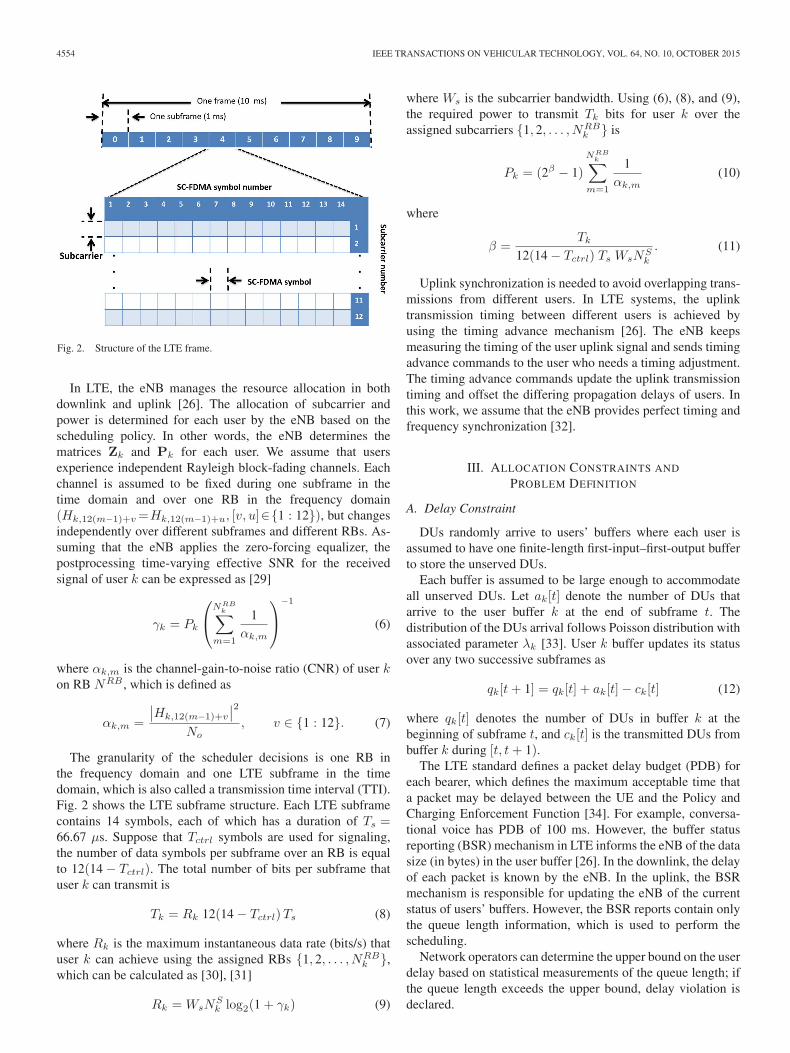
Fig. 2. Structure of the LTE frame.
In LTE, the eNB manages the resource allocation in bothdownlink and uplink [26]. The allocation of subcarrier andpower is determined for each user by the eNB based on thescheduling policy. In other words, the eNB determines thematrices Zk and Pk for each user. We assume that usersexperience independent Rayleigh block-fading channels. Eachchannel is assumed to be fixed during one subframe in thetime domain and over one RB in the frequency domain(Hk,12(m−1)+v=Hk,12(m−1)+u, [v, u]∈{1 : 12}), but changesindependently over different subframes and different RBs. As-suming that the eNB applies the zero-forcing equalizer, thepostprocessing time-varying effective SNR for the receivedsignal of user k can be expressed as [29]
γk = Pk
⎛⎝NRB
k∑m=1
1αk,m
⎞⎠
−1
(6)
where αk,m is the channel-gain-to-noise ratio (CNR) of user kon RB NRB , which is defined as
αk,m =
∣∣Hk,12(m−1)+v
∣∣2No
, v ∈ {1 : 12}. (7)
The granularity of the scheduler decisions is one RB inthe frequency domain and one LTE subframe in the timedomain, which is also called a transmission time interval (TTI).Fig. 2 shows the LTE subframe structure. Each LTE subframecontains 14 symbols, each of which has a duration of Ts =66.67 μs. Suppose that Tctrl symbols are used for signaling,the number of data symbols per subframe over an RB is equalto 12(14 − Tctrl). The total number of bits per subframe thatuser k can transmit is
Tk = Rk 12(14 − Tctrl)Ts (8)
where Rk is the maximum instantaneous data rate (bits/s) thatuser k can achieve using the assigned RBs {1, 2, . . . , NRB
k },which can be calculated as [30], [31]
Rk = WsNSk log2(1 + γk) (9)
where Ws is the subcarrier bandwidth. Using (6), (8), and (9),the required power to transmit Tk bits for user k over theassigned subcarriers {1, 2, . . . , NRB
k } is
Pk = (2β − 1)
NRBk∑
m=1
1αk,m
(10)
where
β =Tk
12(14 − Tctrl) Ts WsNSk
. (11)
Uplink synchronization is needed to avoid overlapping trans-missions from different users. In LTE systems, the uplinktransmission timing between different users is achieved byusing the timing advance mechanism [26]. The eNB keepsmeasuring the timing of the user uplink signal and sends timingadvance commands to the user who needs a timing adjustment.The timing advance commands update the uplink transmissiontiming and offset the differing propagation delays of users. Inthis work, we assume that the eNB provides perfect timing andfrequency synchronization [32].
III. ALLOCATION CONSTRAINTS AND
PROBLEM DEFINITION
A. Delay Constraint
DUs randomly arrive to users’ buffers where each user isassumed to have one finite-length first-input–first-output bufferto store the unserved DUs.
Each buffer is assumed to be large enough to accommodateall unserved DUs. Let ak[t] denote the number of DUs thatarrive to the user buffer k at the end of subframe t. Thedistribution of the DUs arrival follows Poisson distribution withassociated parameter λk [33]. User k buffer updates its statusover any two successive subframes as
qk[t+ 1] = qk[t] + ak[t]− ck[t] (12)
where qk[t] denotes the number of DUs in buffer k at thebeginning of subframe t, and ck[t] is the transmitted DUs frombuffer k during [t, t+ 1).
The LTE standard defines a packet delay budget (PDB) foreach bearer, which defines the maximum acceptable time thata packet may be delayed between the UE and the Policy andCharging Enforcement Function [34]. For example, conversa-tional voice has PDB of 100 ms. However, the buffer statusreporting (BSR) mechanism in LTE informs the eNB of the datasize (in bytes) in the user buffer [26]. In the downlink, the delayof each packet is known by the eNB. In the uplink, the BSRmechanism is responsible for updating the eNB of the currentstatus of users’ buffers. However, the BSR reports contain onlythe queue length information, which is used to perform thescheduling.
Network operators can determine the upper bound on the userdelay based on statistical measurements of the queue length; ifthe queue length exceeds the upper bound, delay violation isdeclared.

KALIL et al.: SCHEDULERS FOR LTE UPLINK WITH DELAY-SENSITIVE TRAFFIC 4555
Fig. 3. Contiguous allocations possible from three RBs.
In this work, we assume that the delay requirements for thedata delivery of user k is satisfied if
qk[t] ≤ qmaxk ∀ t (13)
where qmaxk is an integer number associated with the PDB.
However, once the number of DUs exceeds qmaxk , delay vio-
lation is declared, but no DU is discarded.
B. System Constraints
Three types of constraints restrict the scheduling in the LTEuplink: 1) Contiguity constraint: SC-FDMA restricts the RBallocation to only contiguous allocations, which means that ifa user is assigned more than one RB, the assigned RBs shouldbe adjacent to each other. The set that contains all possiblecontiguous allocations is denoted as b = {b1, b2, . . . , bNb},where bi is the contiguous-allocation number i, and N b is thetotal number of possible contiguous allocations that can beconstructed from x RBs, which can be calculated as [14]
N b =12x(x+ 1) + 1. (14)
Fig. 3 shows an example of the set b for three RBs. Thecontiguity constraint can be maintained by allocating adjacentRBs to every user. 2) Exclusivity constraint: Each RB shouldnot be assigned to more than one user. 3) Power constraint: Thislimits the the maximum transmit power per user to a thresholdspecified by the LTE standard. This restriction is required toensure that the transmitter power amplifier is operating in thelinear region. The power constraint is satisfied by maintainingthe following inequality:
Pk[t] ≤ Pmax ∀ t (15)
where Pmax is the transmit power threshold.
C. Problem Definition
This work aims at minimizing the total power transmitted byall users while satisfying the delay constraints. This optimiza-tion problem can be formulated as
min limτ→∞
1τ
NU∑k=1
τ∑t=1
Pk[t] (16a)
subject to
qk[t] ≤ qmaxk ∀ k (16b)
Ik[t] ∈b ∀ k (16c)
Iu[t]∩ Iv[t] = φ ∀u = v (16d)
Pk[t] ≤Pmax ∀ k (16e)
where Ik[t] represents the contiguous allocation assigned touser k at subframe t. The constraints in (16b)–(16e) assurethat the delay, exclusive allocation, contiguity allocation, andmaximum allowable power transmit constraints are satisfied.
In this work, we assume that the system can maintain thedelay requirements of all users, and feasible solutions exist.However, if the data arrival rates are high, the optimization in(16) could be infeasible, and hence, an admission control policyis needed [35].
IV. OPTIMAL OFFLINE SCHEDULING
Here, an offline optimal solution for (16) is obtained usingDP. The problem in (16) is optimally structured, i.e., it isdivided into stages, each of which has a duration of one sub-frame. By assuming that the scheduler has perfect knowledgeof both future DU arrivals and future channel realizationsbefore scheduling, the problem in (16) can be expressed as adeterministic DP problem. Although this assumption makes thesystem noncausal, it provides the optimal solution that can beused as a reference for other suboptimal algorithms.
Having said that, it is worth noting that such assumptions arenot always overoptimistic because DU arrivals can be predictedfor certain applications such as voice over IP, and future channelstate information can be accurately estimated in slow time-varying channels [36], [37].
In this work, we assume that the system is observed over afinite number of subframes (stages) τ . Three main elementsdefine the DP, namely, stages, states, and actions, which aredescribed as follows.
• Stages: DP breaks up the entire problem into stages, andeach stage forms a new subproblem. The new subprob-lems are smaller and, consequently, less computationallyexpensive to solve compared with the entire problem. Theoptimal solution of the entire problem can be achievedby solving all subproblems individually. For the problemconsidered in this work, the stage is defined as one sub-frame in time.
• States: Every stage has a number of possible states.Information about the states at each stage is essential tosolve the subproblems. To avoid confusion, two types ofstates, namely, user states and joint states, are defined. Atsubframe t, the state of user k is denoted by qk[t] anddefined as the number of DUs that exist in the bufferof user k. The joint state at stage t is defined as thejoint states of all users at subframe t, which can be ex-pressed as
s[t] = [q1[t], q2[t], . . . , qNU [t]] . (17)

4556 IEEE TRANSACTIONS ON VEHICULAR TECHNOLOGY, VOL. 64, NO. 10, OCTOBER 2015
Fig. 4. Components and the optimal action path of the DP problem.
Given that the maximum allowable delay of user k is qmaxk
DUs, the possible states of user k are [0, 1, . . . , qmaxk ].
User k has qk[t] + 1 possible states at stage t. Therefore,the total number of joint states at stage t is
N js[t] =
NU∏k=1
(1 + qk[t]) . (18)
• Actions: These are defined as the number of DUs a usertransmits at a stage. Actions are taken at every stage forall users and update their states. As users compete for thesame radio resources, the actions for each user dependon the action taken for the other users. As a result, thejoint actions should be taken into account by the dynamicalgorithm. The joint actions are defined as the number oftransmit DUs per subframe for each user. Fig. 4 showsthe components and the optimal action path of the DPproblem.
To simplify the DP analysis, we assume that users canonly send a finite number of DUs during any TTI. Theaction set that user k can take at stage t is denoted by
ck[t] ∈ {0, 1, 2, . . . ,min (qk[t], cmaxk )} ∀ k (19)
where cmaxk is the maximum number of DUs that user k is
allowed to transmit per subframe. Note that (19) impliesthat user k cannot take any action at stage t that transmitsdata more than its buffer length.
The joint action at stage t is described as joint transmis-sion decisions for all users, and it is denoted by
c[t] = [c1[t], c2[t], . . . , cNU [t]] . (20)
Therefore, the number of joint actions at stage t is
N ja[t] =
NU∏k=1
(1 +min (qk[t], cmaxk )) . (21)
In fact, different possible distributions of the RBs betweenusers may exist for one joint action. Consequently, differentRB allocations may result in different costs with the same jointaction. For example, assume a system of two users who sharethree RBs. All possible RB allocations for the two users for
Fig. 5. Example of all possible RB allocations for a system consisting of threeRBs shared between two users.
each action are shown in Fig. 5. As channel gain varies overRBs, each RB allocation is associated with a cost that canbe calculated using (10). As a result, each joint action in thisexample may be related to nine different joint costs, dependingon how the RBs are assigned to the users.
As our objective is to minimize the total transmit power, find-ing the minimum joint cost for each action results in minimizingthe total transmit power. Therefore, for each action, the RBsshould be allocated to the users such that the cost is minimized.Nevertheless, finding the actions’ minimum joint costs is nottrivial, particularly for systems with a large number of usersand RBs.
Joint Action Cost Minimization: Finding the minimum costfor each joint action is a combinatorial problem, which canbe formulated as a BIP problem as follows. Assume that thecurrent subframe is t, the minimum cost for the joint actionc[t] = [c1[t], c2[t], . . . , cNU [t]] can be found by solving thefollowing optimization problem:
P (c, t) = min
NU∑k=1
B∑b=1
Pk[t] (k, bi) (22a)
subject to
NU⋂k=1
(k, bi) =φ ∀ i (22b)
Pk[t] ≤Pmax (22c)
Tk[t] = ck[t] Lk ∀ k (22d)
where Lk is user k DU length (in bits), c is a generic value ofc[t], and (k, bi) is a binary number defined as
(k, bi) ={
1, if the allocation bi is assigned to user k.
0, otherwise.(23)
KALIL et al.: SCHEDULERS FOR LTE UPLINK WITH DELAY-SENSITIVE TRAFFIC 4557
Although data are delivered in packets of several sizes, theymay be split into several DUs or may be combined into a singleDU. Here, we assume that Lk is a fixed value for each user;however, a user can transmit one or more DUs in each TTI. Forexample, if Lk = 100 bits and cmax
k = 3, user k can transmit100, 200, or 300 bits in each TTI.
The constraint in (22b) maintains exclusive RB allocationsand prevents overlapping allocations. It is worth noting thatfeasible solutions for (22) are not guaranteed. If no feasiblesolutions exists, the cost of the joint action is assigned as ∞.
A main limitation for the DP is that the complexity of suchalgorithms exponentially increases as a function of the numberof possible actions at each stage. Although solving BIP for eachjoint action is computationally expensive, it results in reducingthe computational complexity of the DP algorithm. Instead ofconsidering all RB allocation possibilities for one joint actionas new joint actions, they reduce to only one joint action.
The Basic DP Algorithm: The joint state updates as follows:
s[t+ 1] = s[t]− c[t] + a[t] (24)
where a[t] presents all users’ arrival DUs at subframe t, i.e.,
a[t] = [a1[t], a2[t], . . . , aNU [t]] . (25)
The problem in (16) can be presented as an optimal controlproblem as follows:
minc
1τ
τ∑t=1
P (c, s, t) (26)
where P (c, s, t) = P (c, t) + PI(s, t), and PI(s, t) is a penaltycost of infeasible states, which is defined as
PI(s, t) =
{∞, if s is infeasible
0, if s is feasible.(27)
User k reaches an infeasible state at subframe t if the numberof the unserved bits in the user’s buffer exceeds the maximumallowed queue length, i.e., qk[t] > qmax
k .Initial- and final-state settings: Assume that all users’
buffers are empty at both the initial subframe (t = 1) and finalsubframe (t = τ). Moreover, we assume that no data arrivefor any users at time t ≥ τ . In other words, a[t] = 0NU |t ≥ τ ,where 0NU is a vector of zeros with a length of NU . There-fore, the first and the τ + 1 joint states can be presented,respectively, as s[1] = a[1]− c[1], and s[τ + 1] = 0NU .
Let F (s, t) be the minimum future cost obtained by optimiz-ing the problem over subframes t, t+ 1, . . . , τ + 1, where s isa generic value of s[t]. The DP equation, which is also knownas the Bellman equation, can be written as
F (s, t) =
{minc
{P (c, s, t)+F (s−c+ a, t+ 1)} , t ≤ τ
0, t > τ.(28)
Note that the optimization in (28) is unconstrained becauseall the constraints are considered in P (c, s, t) = P (c, t) +
PI(s, t). The exclusive allocation, contiguity allocation, andmaximum allowable transmit power (MATP) constraints areconsidered in P (c, t), as illustrated in (16). The delay constraintis considered in PI(s, t) as discussed in (27).
Let c∗t be the optimal action at subframe t given that the jointstate of subframe t is s∗t . The optimal scheduling policy for DPis denoted as Θ∗ = {c∗1, c∗2, . . . , c∗τ}, and it is defined as a setof joint actions that should be taken across all the stages suchthat the total cost function is minimized.
The DP equation presented in (28) is a recursive loop. Ateach subframe, the optimal action ct is only a function of thejoint state st. Thus, the optimal action at the current time doesnot depend on the past actions taken. Furthermore, the DPequation is backward in time, which means that the sequenceof optimal actions is determined starting from the final stageand ending at the initial stage. The solution of the DP equationworks in reverse as follows. The value of F (s, τ + 1) is knownand equal to zero. Using (28), F (s, τ) can be calculated as
F (s, τ) = minc
{P (c, s, τ) + 0} . (29)
As a result, F (s, τ − 1) can be iteratively calculated untilF (s, 1) is reached, which is the minimum total power trans-mitted during [1, τ ]. Thus, the optimization in (26) can be pre-sented as
minc
1τ
τ∑t=1
P (c, s, t) = mins∈s[1]
F (s, 1)τ
. (30)
V. SUBOPTIMAL POWER-EFFICIENT SCHEDULERS
Although DP provides global optimal solutions, it is non-causal and computationally expensive.
The BSR mechanism is responsible for informing the eNBabout the current size of users’ queues. The BSR is triggedwhen new data arrive in an empty buffer, when new datathat have higher priority than that in the buffer arrive, orwhen the timer for BSR (periodicBSR-Timer) expires [26].The LTE standard defines the minimum value of the timer forBSR reporting to be five subframes [38], which is assumed inthis work.
The DP is computationally complex for two reasons. First,it has a large number of states and actions, and second, itsolves a BIP problem for each joint action. As a result, low-complexity solutions are needed for practical systems. To min-imize the total transmit power and satisfy the delay constraints,three main elements should be considered while scheduling thesystem resources. First, data transmission at high data rates isconvenient for satisfying the delay constraints. However, high-data-rate transmission is less power efficient than transmittingat low data rates [16], [17]. Second, the total transmit powercan be reduced by efficiently allocating the radio resourcesbetween users. As seen from (10), the transmit power decreasesas the channel conditions improve. Third, the scheduler shouldbe agile to accommodate for channel variations. For example,the scheduler may decide to transmit high data rates when thechannel is good, whereas low data rates can be transmittedunder poor channel conditions. Based on the aforementioned

4558 IEEE TRANSACTIONS ON VEHICULAR TECHNOLOGY, VOL. 64, NO. 10, OCTOBER 2015
TABLE IIMTPC SCHEDULER
three observations, we propose two heuristic algorithms thatsolve the scheduling problem for the LTE uplink. The proposedalgorithms depend on the channel quality and users’ bufferlengths.
A. MTPC Scheduler
The maximum transmit power controlling (MTPC) schedulerminimizes the total transmit power by preventing users fromtransmitting at the maximum power levels, unless it is necessaryto meet the delay constraints. The objective is to maximizethe total transmit DUs for all users subject to MATP levelspmaxk < Pmax. The principal idea of the MTPC scheduler is
to adapt the users’ MATP levels based on their data queuelengths. The algorithm increases MATP levels for users whoexperience increase in their data queue length. On the otherhand, MATP levels can be decreased for users who experiencea decreasing queue length. In other words, the scheduler allowsusers who are demanding high QoS to increase their MATPand, accordingly, transmit using higher rates to meet their QoSrequirement. In contrast, to save power, MATPs are decreasedfor users who have low traffic load.
The pseudocode in Table II describes the MTPC scheduler.The operator Ω(RBk, p
maxk ) computes the maximum number
of DUs that can be transmitted over RB chunk RBk whilepk ≤ pmax
k . For each iteration, a single RB is allocated to thewinning user who maximizes Gain(k∗), where Gain(k∗) isthe gain user k∗ achieves after granting the RB. The functionΛ(pmax
k , qk[t]) dynamically updates the MATP level for the
next subframes, which is discussed in Section V-D. The MTPCpseudocode can be illustrated as follows.
• Lines 4–9 find the best feasible RB for each user consid-ering the contiguous-allocation constraint. If a user hasno allocation, the scheduler chooses the feasible RB withthe highest channel gain (line 5). In case a user has beenassigned one or more RBs, the scheduler chooses thefeasible RB with the highest channel gain that is next tothe allocated RB chunk to that user (lines 7–9). The twooperations max|RBk| and min |RBk| find the highest RBnumber and the lowest RB number that are assigned touser k. Consequently, max |RBk|+ 1 and min|RBk| − 1denote the number of positional RBs that are adjacent tothe RB chunk RBk.
• Lines 11–15 compute Gain(k), which denotes the poten-tial increase in the number of transmit DUs by adding thebest feasible RB found in lines 4–9. If the potential newallocation adds no positive gain to the user, the Gain(k)is set to −1.
• Lines 17–22 determine the winning user (k∗) whoachieved the maximum Gain(k∗), then assign the asso-ciated Vk∗ to the winning user, and take Vk∗ from theunallocated RBs set RB.
• Lines 24–25 update the MATP level for all users based ontheir queue lengths.
B. BWC Scheduler
The bit-per-watt controlling (BWC) scheduler controls theminimum acceptable bit-per-watt ratio (BPWR) for each user.Consequently, the users do not waste their power on transmis-sion when the channel conditions are poor, and a certain levelof transmit power efficiency is maintained. However, whenthe users’ queue lengths increase, the scheduler decreases theBPWR assigned to them. As a result, the scheduler pushes theusers to transmit more DUs and satisfy the delay requirement athigh power consumption expense.
The BPWR at subframe t is denoted by Wk[t], which isdefined as the number of bits transmitted per watt, i.e.,
Wk[t] =Tk[t]
Pk[t].
Denote Γ(RBk,Wmink [t]) as the maximum number of DUs
that can be transmitted over the RB chunk RBk such asWk[t] ≥ Wmin
k [t], where Wmink [t] is the minimum acceptable
BPWR at subframe t. The function Ξ(Wmink , qk[t]) dynami-
cally updates the minimum acceptable BPWR, which is dis-cussed in Section V-D.
The minimum acceptable BPWR is updated based on theusers’ queue lengths. For users who experience reduction intheir queue length, the minimum acceptable BPWR is in-creased; otherwise, it will be decreased.
The BWC scheduler allocates RBs to users iteratively similarto the MTPC scheduler. At each iteration, one RB is allo-cated to the winning user k∗ who maximizes Gain(k∗), whereGain(k∗) is the difference between the number of DUs that
KALIL et al.: SCHEDULERS FOR LTE UPLINK WITH DELAY-SENSITIVE TRAFFIC 4559
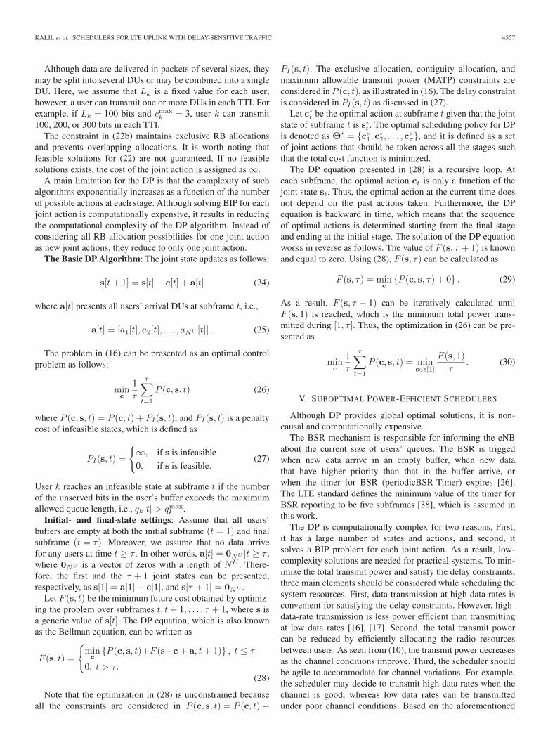
TABLE IIIBWC SCHEDULER
can be transmitted after and before assigning the potential RBto user k∗ and satisfies Wk∗ [t] ≥ Wmin
k∗ [t]. The pseudocodein Table III describes the BWC scheduler. In lines 4–9, thescheduler finds the best RB for every user, which has the highestCNR and maintains the contiguous-allocation constraint. Thepotential gains Gain(k) ∀ k that are resulted from assigningthe potential best RBs that are found in lines 4–9 are computedin lines 11–15. If user k has a negative gain, Gain(k) is setto −1. Lines 17–19 stop the algorithm if Gain(k) < 0 ∀ k.The winning user (k∗) is defined as the user who achieves themaximum Gain(k∗) and is determined by line 20, whereasin line 21, the RB is assigned, and the unallocated-RB set isupdated. Based on the queue length, BPWRs are updated for allusers in lines 24–25.
C. Complexity of the Heuristic Algorithms
The first iteration of both algorithms should find the bestRB for each user. Finding the best RB, which has the max-imum SNR, for a user requires NRB operations. Therefore,the first iteration requires NU ×NRB operations. Finding themaximum number of DUs that can be transmitted over the bestRB of user k requires, at most, cmax
k operations. As constantsand low-order terms do not determine the complexity order, thefirst iteration complexity is O(NU ×NRB). The first iterationassigns an RB to a user. In the second iteration, the number ofthe remaining RBs is NRB − 1. The best-case scenario is whenthe assigned RB in the first iteration is not a best RB for anyother users. In other words, each user has a distinct best RB. Inthis case, no more operations are required for the next iteration
TABLE IVMATP CONTROLLER
TABLE VBPWR CONTROLLER
because users know their best RBs, which are the same as in theprevious iteration. Therefore, the best-case scenario complexityis O(NU ×NRB). Nevertheless, the worst-case scenario iswhen the assigned RB in the first iteration is the best RB for allusers. This requires finding the second best RB for every user,which requires O((NU − 1)× (NRB − 1)) operations. For allNRB iterations, the complexity of the worst-case scenario isO(NU × (NRB)
2).
The heuristics algorithms can be implemented more effi-ciently using sorting algorithms, such as Quicksort. The SNR ofthe RBs are sorted for each user. Sorting NRB RBs requires, onaverage, NRB × log(NRB) operations. Consequently, NU ×NRB log(NRB) operations are required to sort the RBs for NU
UEs. Finding the best RB of a sorted array is O(1). The seconditeration requires only NU operations to delete the assignedRB from the sorted SNR value array of every user. Thus,the complexity of iterations 2, 3, . . . , NRB is O(NU ×NRB).Therefore, the algorithms’ complexity is determined by thefirst iteration, which has complexity of NU ×NRB log(NRB).As the maximum number of RBs in LTE systems is 100[26], the worst-case complexity is O(100NU × log(100)) ≈O(NU ) if NU � NRB . For a scenario of low number of activeusers (NRB � NU ), the worst-case complexity is O(NRB ×log(NRB)).
D. Controllers
For the two proposed algorithms, controllers are needed tocontrol the MATP and the BPWR in accordance with buffers’queue lengths. We assume that the MATP and the BPWR areupdated every l LTE subframes. Let ϑH and ϑL be positive realnumbers between [0, 1] such that ϑH > ϑL. When the queuelength of a user’s buffer is greater than ϑHqmax
k , the user expe-riences high queue length. However, when the queue length ofthe user’s buffer is less than ϑLq
maxk , the user experiences low
queue length.

4560 IEEE TRANSACTIONS ON VEHICULAR TECHNOLOGY, VOL. 64, NO. 10, OCTOBER 2015
TABLE VIPARAMETER SETTINGS OF THE UPLINK LTE MODEL
Table IV presents a low-complexity controller for the MATPscheduler. The MATP is set to its maximum Pmax when thequeue length of the user’s buffer is greater than ϑHqmax
k . SettingMATP to the maximum means that data are transmitted at thehighest possible data rates, regardless of the power consump-tion. Therefore, the controller checks that if a user experiencesa critical queue length, the user is allowed to transmit usingthe maximum possible transmit power. If the queue length ofthe user’s buffer is less than ϑLq
maxk , the MATP decreases by
δR. However, if the user queue length is between ϑHqmaxk and
ϑLqmaxk , the MATP is controlled using (sign(Δk)), which is the
sign of difference between q̄k,t−l:t−l and q̄k,t−l:t, where q̄k,u:vis the average queue length over the TTI u : v. If sign(Δk)is positive, the queue length is increased, and the MATPshould increase to allow the user to transmit more data, andvice versa.
Table V presents a low-complexity controller for the BPWRscheduler. The BPWR controller is similar to the MATP con-troller. When the queue length of the user buffers is greaterthan ϑHqmax
k , the BPWR is set to zero. If the queue lengthof the user’s buffer is less than ϑLq
maxk , the BPWR decreases
by δ2. However, if the user queue length is between ϑHqmaxk
and ϑLqmaxk , the BPWR is controlled based on (sign(Δk)). The
positive sign(Δk) values imply that the queue length increasedand the BPWR level should decrease to allow the users totransmit more DUs at the expense of low bit-per-watt metricvalues. On the other hand, when the queue length decreases,the sign(Δk) value is negative, and the BPWR level decreasesto force transmission at high bit-per-watt metric values.
VI. SIMULATION RESULTS
The performance of the proposed schedulers is evaluatedusing MATLAB system-level simulation based on the uplinkLTE model.
The simulated model consists of two users with differentQoS requirements and arrival rates. We assume that bothusers experience identical channel conditions in terms of thereceived average CNR. Table VI summarizes the consideredsimulation parameters. The performance of the proposed DPand heuristic schedulers is compared with each other as wellas with a nonadaptive scheduler and with the greedy algorithmpresented in [16]. The nonadaptive scheduler is similar to theMTPC scheduler, but the MATP levels are fixed to Pmax.The nonadaptive scheduler transmits at the maximum possibledata rate regardless of the channel condition or the bufferqueue length. As a matter of fact, the nonadaptive scheduler
Fig. 6. Average transmit power per TTI.
can be seen as the BWCA scheduler with Wmink [t] = 0, ∀ t,
and ∀ k.Fig. 6 shows the average user transmit power per TTI. As
the average channel gain increases, the average transmit powerdecreases for all the considered scheduler and user scenarios.
As shown in (10), the transmit power is inversely propor-tional to the channel gain. Therefore, increasing the averagechannel gain reduces the transmit power. The DP consumesthe least average transmit power compared with the otherschedulers. The DP scheduler provides the optimal solution,in which both the channel gains and the data arrival rates areknown for the whole scheduling time before the schedulingbegins. Since it has a higher arrival rate, UE2 transmits moreDUs and consumes higher power than UE1. Since λ2 > λ1,the average transmitted data of UE2 are higher than that ofUE1. Consequently, UE2 consumes more power than UE1.The performance of the MTPC scheduler outperforms theperformance of BWC. The nonadaptive scheduler consumesthe highest power among the schedulers. On average, MTPCand BWC schedulers consume 0.6% and 0.70% of the powerconsumed by the nonadaptive scheduler, respectively.
For the worst-case scenario, the 95% confidence intervals(CIs) of the results presented in Fig. 6 are as follows. ForUE1, the CIs for the MTPC, BWC, nonadaptive, and optimalschedulers are within ±2%, ±2.2%, ±2.4%, and ±1.1%, re-spectively. For UE2, the CIs for the MTPC, BWC, nonadaptive,and optimal schedulers are within ±3.0%, ±3.6%, ±3.6%, and±1.7%, respectively.
KALIL et al.: SCHEDULERS FOR LTE UPLINK WITH DELAY-SENSITIVE TRAFFIC 4561
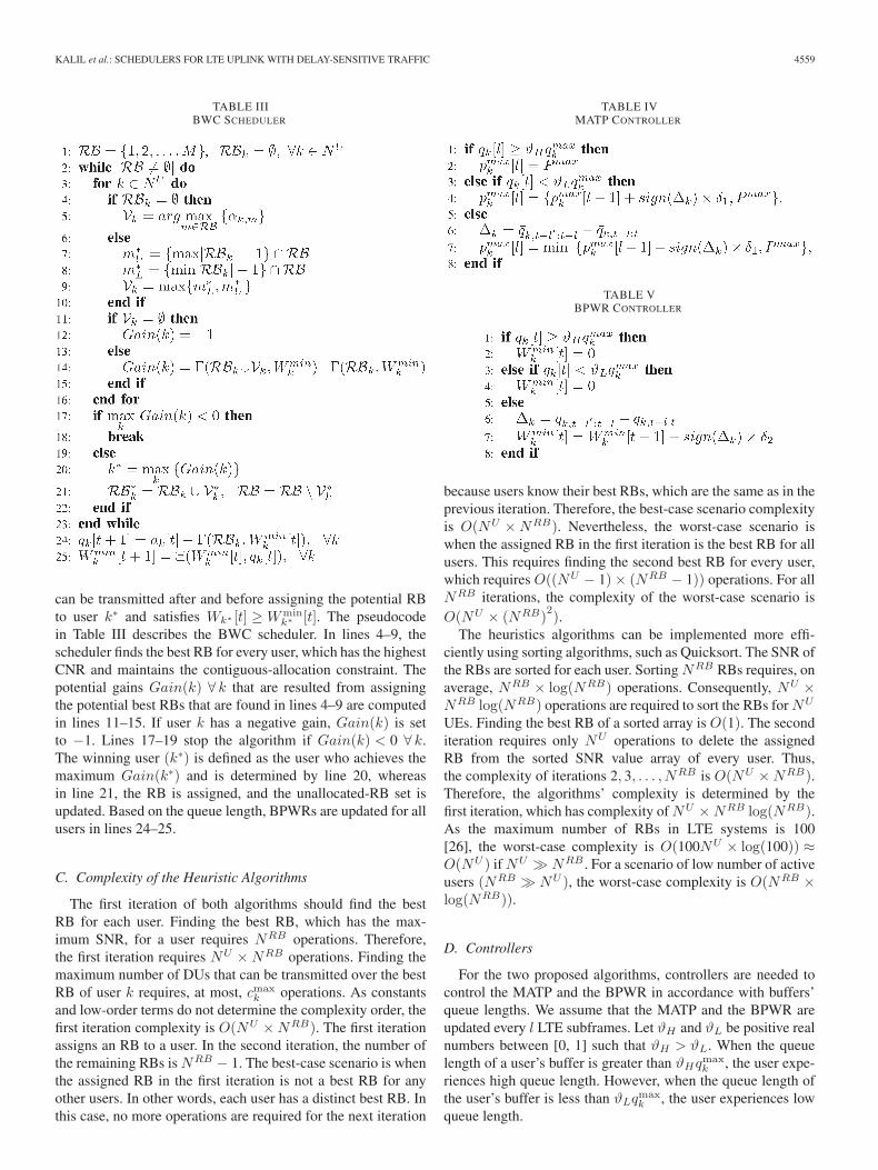
Fig. 7. Average queue length for UE1.
Fig. 8. Average queue length for UE2.
Figs. 7 and 8 present the average queue length of UE1and UE2, respectively. Although the DP scheduler experiencesthe highest average queue length, it guarantees that no delayviolation occurs. On average, for the MTPC and BWC sched-ulers, the user queue lengths are 57% and 80% less than thequeue length resulted by the DP solution, respectively. Thenonadaptive scheduler experiences an average queue length7.5 times less than the DP scheduler. The nonadaptive schedulertends to transmit data at the possible maximum rates, whichreduces the average queue lengths at the expense of highertransmit power.
The 95% CIs for the average queue length for the MTPC,BWC, nonadaptive, and optimal schedulers are less than±1.4%, ±2.1%, ±3.0%, and ±1.2%, respectively.
Figs. 9 and 10 show the probability density functions (pdfs)of the queue length of UE1 and UE2, respectively. The pdfs ofthe nonadaptive and the BWC schedulers are similar and almostconfined between 0 and 0.3qmax
k . The queue length pdfs forthe MTPC are similar to the pdf for the optimal solution. Thepdfs for the MTPC and BWC schedulers drop when the queue
Fig. 9. PDF of the queue length for UE1 (average CNR = 13 dB).
Fig. 10. PDF of the queue length for UE2 (average CNR = 13 dB).
lengths approach ϑHqmaxk until they reach zero for queue length
over than qmaxk . When a queue length reaches ϑHqmax
k , bothschedulers allow the user to transmit at the highest rate possible,which results in zeroing the queue length pdfs for values overϑHqmax
k .However, the DP scheduler knows the arrival rate and the
channel gain before scheduling, and it manages the delay tobe less than the maximum allowed delay and reduces the totalpower transmit. Therefore, the queue length pdfs for the DPscheduler show the highest values among the schedulers aroundthe maximum allowed delay value.
A. Large-Scale Scenario
Here, the iterative algorithms are evaluated for a large-scalescenario. As the DP complexity exponentially increases withthe problem size, the optimal solution is not included forthe large-scale scenario. Table VII summarizes the simulationparameters for the large-scale scenario.

4562 IEEE TRANSACTIONS ON VEHICULAR TECHNOLOGY, VOL. 64, NO. 10, OCTOBER 2015
TABLE VIIPARAMETER SETTINGS OF THE LARGE-SCALE SCENARIO
Fig. 11. Average transmit power per TTI for the large-scale scenario.
Fig. 12. Average queue length for all users for the large-scale scenario.
Figs. 11 and 12 show the average user transmit power per TTIand the average queue length (DU), respectively. As the numberof users increases, the competition for the radio resourcesincreases, leading to transmission of more power and growthin queue lengths for all schedulers.
The average queue length is inversely proportional to thepower consumed by the schedulers. The MTPC scheduler con-sumes the least power compared with the BWC, greedy [16],and nonadaptive schedulers. However, users experience thehighest average queue lengths. On the other hand, the nonadap-tive scheduler has the least queue length but consumes the mostpower among the schedulers.
The 95% CIs for the average transmit power and the averagequeue lengths for both schedulers are less than ±1%.
Fig. 13. PDF of the queue length for number of users 70.
Fig. 14. Average transmit power for all users per TTI for different l.
Fig. 13 shows the pdfs of the queue lengths averaged onall users. For all schedulers, the average queue length is lowerthan the maximum allowed (200 DUs), which means no delayviolation has occurred.
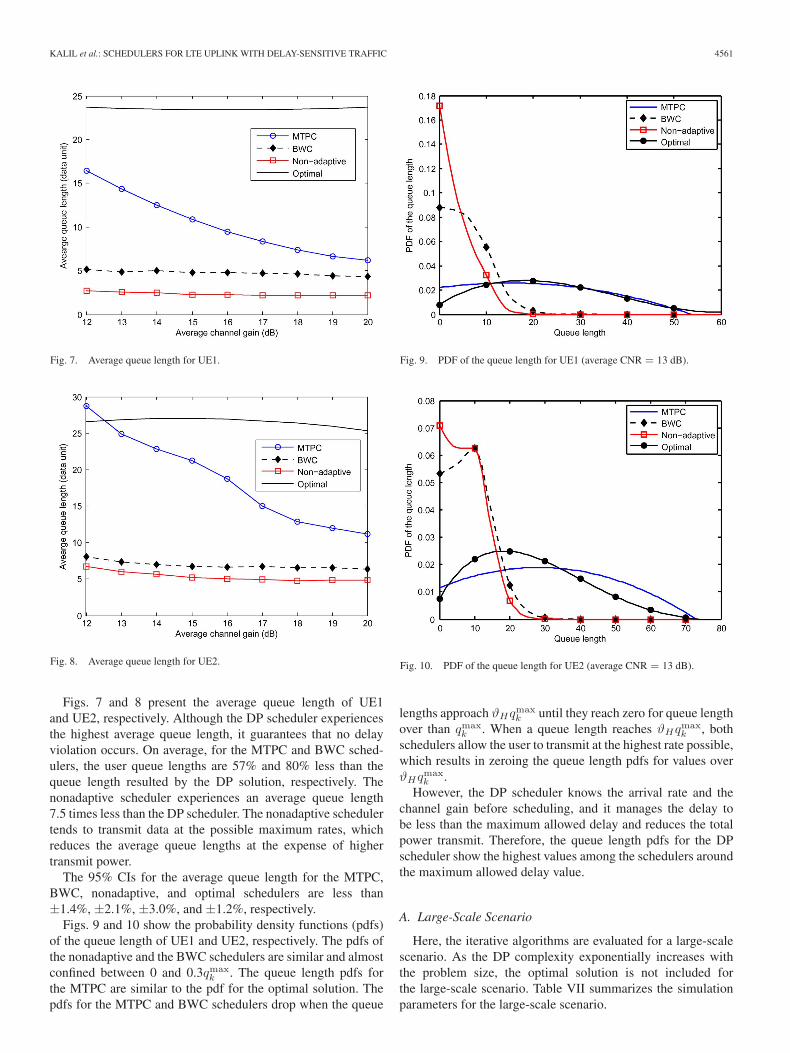
Figs. 14 and 15 show the average transmit power and queuelength for the MTPC and BWC schedulers across differentvalues of l. As l increases, the power consumption slightlyincreases, and the average queue length decreases for bothschedulers. Note that the MATP and the BPWR are updatedonce every l subframes. Updating the MATP and BPWR athigher rates allows the schedulers to save more power. How-ever, updating the MATP and BPWR at lower rates decreasesthe delay as a result of transmitting at a higher data rate at theexpense of the power consumption.
KALIL et al.: SCHEDULERS FOR LTE UPLINK WITH DELAY-SENSITIVE TRAFFIC 4563
Fig. 15. Average queue length for all users for different l.
VII. CONCLUSION
In this paper, we have considered the problem of minimizingtransmit power subject to delay constraints for the LTE uplinksystems. We have derived the optimal solution based on a DPapproach. The scheduling problem is divided into stages; eachstage has a number of states based on the queue length of theusers’ buffers. Actions are taken at each stage based on thechannel quality and the queue length. BIP is invoked to findthe minimum cost for each action. The minimum action costsresults from optimally allocating the RBs to the users. Afterfinding the minimum cost for each action, the optimal actionsare derived by solving the dynamic equation backward startingfrom the last stage until the first stage. Consequently, we haveproposed two online schedulers that solve the scheduling prob-lem with comparable power consumption. The schedulers arebased on a low-computational-complexity heuristic algorithm.The first scheduler adapts the MATP for every user accordingto the queue length of the user’s buffer. The scheduler preventsthe user from transmitting at high power levels when the bufferqueue length is low. However, the second scheduler controlsthe minimum acceptable BPWR for each user. Users can onlytransmit if they experience BPWR greater than a minimumacceptable BPWR. For the online schedulers, controllers arederived to adapt the MATP and BPWR levels for users based onthe queue length of their buffers. The online-scheduler perfor-mances are compared with the optimal and existing schedulersin terms of transmit power and delay.
REFERENCES
[1] Cisco visual networking index: Global mobile data traffic forecast update,2013-20187, Cisco, San Jose, CA, USA, Tech. Rep. 2013.
[2] L. Zhang et al., “Accurate online power estimation and automatic batterybehavior based power model generation for smartphones,” in Proc. 8thIEEE/ACM/IFIP Int. Conf. Hardware/Softw. Codesign Syst. Synthesis,2010, pp. 105–114.
[3] N. Ding, D. Wagner, X. Chen, Y. C. Hu, and A. Rice, “Characterizing andmodeling the impact of wireless signal strength on smartphone batterydrain,” in Proc. ACM SIGMETRICS/Int. Conf. Meas. Model. Comput.Syst., 2013, pp. 29–40.
[4] J. Huang et al., “A close examination of performance and power charac-teristics of 4G LTE networks,” in Proc. 10th Int. Conf. Mobile Syst. Appl.Serv., 2012, pp. 225–238.
[5] E. Yaacoub and Z. Dawy, “A survey on uplink resource allocation inOFDMA wireless networks,” IEEE, Commun. Surveys Tuts., vol. 14,no. 2, pp. 322–337, May 2012.
[6] T. Wang, F. Glineur, J. Louveaux, and L. Vandendorpe, “Weighted sumrate maximization for downlink OFDMA with subcarrier-pair based op-portunistic DF relaying,” IEEE Trans. Signal Process., vol. 61, no. 10,pp. 2512–2524, May 2013.
[7] C. Y. Wong, R. Cheng, K. Lataief, and R. Murch, “Multiuser OFDMwith adaptive subcarrier, bit, and power allocation,” IEEE J. Sel. AreasCommun., vol. 17, no. 10, pp. 1747–1758, Oct. 1999.
[8] H. Boche and M. Schubert, “ Nash bargaining and proportional fair-ness for wireless systems,” IEEE/ACM Trans. Netw., vol. 17, no. 5,pp. 1453–1466, Oct. 2009.
[9] W. Yu and R. Lui, “Dual methods for nonconvex spectrum optimiza-tion of multicarrier systems,” IEEE Trans Commun., vol. 54, no. 7,pp. 1310–1322, Jul. 2006.
[10] P. Liu, R. Berry, and M. Honig, “A fluid analysis of a utility-basedwireless scheduling policy,” IEEE Trans. Inf. Theory, vol. 52, no. 7,pp. 2872–2889, Jul. 2006.
[11] M. Shaat and F. Bader, “Asymptotically optimal resource allocation inOFDM-based cognitive networks with multiple relays,” IEEE Trans.Wireless Commun., vol. 11, no. 3, pp. 892–897, Mar. 2012.
[12] V. Lau and C. H. Koh, “Tradeoff analysis of delay-power-CSIT qual-ity of dynamic backpressure algorithm for energy efficient OFDMsystems,” IEEE Trans. Signal Process., vol. 60, no. 8, pp. 4254–4263,Aug. 2012.
[13] M. Mehrjoo, S. Moazeni, and X. S. Shen, “Resource allocation inOFDMA networks based on interior point methods,” Wireless Commun.Mobile Comput., vol. 10, no. 11, pp. 1493–1508, Nov. 2010.
[14] I. Wong, O. Oteri, and W. Mccoy, “Optimal resource allocation in up-link SC-FDMA systems,” IEEE Trans. Wireless Commun., vol. 8, no. 5,pp. 2161–2165, May 2009.
[15] A. Ahmad and M. Assaad, “Polynomial-complexity optimal resourceallocation framework for uplink SC-FDMA systems,” in Proc. IEEEGLOBECOM, Dec. 2011, pp. 1–5.
[16] M. Kalil, A. Shami, and A. Al-Dweik, “Power-efficient QoS scheduler forLTE uplink,” in Proc. IEEE ICC, Jun. 2013, pp. 6200–6204.
[17] M. Kalil, A. Shami, and A. Al-Dweik, “QoS-aware power-efficient sched-uler for LTE uplink,” IEEE Trans. Mobile Comput., vol. 14, no. 8,pp. 1672–1685, Aug. 1, 2015.
[18] D. Dechene and A. Shami, “Energy-aware resource allocation strate-gies for LTE uplink with synchronous HARQ constraints,” IEEE Trans.Mobile Comput., vol. 13, no. 2, pp. 422–433, Feb. 2014.
[19] O. Nwamadi, X. Zhu, and A. Nandi, “Dynamic physical resource blockallocation algorithms for uplink long term evolution,” IET Commun.,vol. 5, no. 7, pp. 1020–1027, May 2011.
[20] J. Kim, D. Kim, and Y. Han, “Proportional fair scheduling algorithmfor SC-FDMA in LTE uplink,” in Proc. IEEE GLOBECOM, Dec. 2012,pp. 4816–4820.
[21] M. Al-Rawi, R. Jantti, J. Torsner, and M. Sagfors, “On the performanceof Heuristic opportunistic scheduling in the uplink of 3G LTE networks,”in Proc. 19th IEEE Int. Symp. PIMRC, 2008, pp. 1–6.
[22] G. Miao, N. Himayat, G. Li, and S. Talwar, “Low-complexity energy-efficient scheduling for uplink OFDMA,” IEEE Trans. Commun., vol. 60,no. 1, pp. 112–120, Jan. 2012.
[23] D. Dechene and A. Shami, “Energy efficient resource allocation in SC-FDMA uplink with synchronous HARQ constraints,” in Proc. IEEE ICC,Jun. 2011, pp. 1–5.
[24] D. Dechene and A. Shami, “Energy efficient QoS constrained sched-uler for SC-FDMA uplink,” Phys. Commun., vol. 8, pp. 81–90,Sep. 2013.
[25] N. Prasad, H. Zhang, H. Zhu, and S. Rangarajan, “Multiuser schedulingin the 3GPP LTE cellular uplink,” IEEE Trans. Mobile Comput., vol. 13,no. 1, pp. 130–145, Jan. 2014.
[26] S. Sesia, I. Toufik, and M. Baker, LTE—The UMTS Long Term Evolution:From Theory to Practice. Hoboken, NJ, USA: Wiley, 2009.
[27] X. Xiang, C. Lin, X. Chen, and X. Shen, “Toward optimal ad-mission control and resource allocation for LTE-A femtocell up-link,” IEEE Trans. Veh. Technol., vol. 64, no. 7, pp. 3247–3261,Jul. 2015.
[28] H. Tabassum, Z. Dawy, M. Alouini, and F. Yilmaz, “A generic inter-ference model for uplink OFDMA networks with fractional frequencyreuse,” IEEE Trans. Veh. Technol., vol. 63, no. 3, pp. 1491–1497,Mar. 2014.

4564 IEEE TRANSACTIONS ON VEHICULAR TECHNOLOGY, VOL. 64, NO. 10, OCTOBER 2015
[29] Simulation methodology for EUTRA UL: IFDMA and DFT-spread-OFDMA, Sophia-Antipolis, France, 3GPP R1-050718, 2005.
[30] C. Xiong, G. Li, S. Zhang, Y. Chen, and S. Xu, “Energy-efficient resourceallocation in OFDMA networks,” IEEE Trans. Commun., vol. 60, no. 12,pp. 3767–3778, Dec. 2012.
[31] A. Goldsmith, Wireless Communications. Cambridge, U.K.: CambridgeUniv. Press, 2005.
[32] R. Xie, F. Yu, H. Ji, and Y. Li, “Energy-efficient resource allocation forHeterogeneous cognitive radio networks with Femtocells,” IEEE Trans.Wireless Commun., vol. 11, no. 11, pp. 3910–3920, Nov. 2012.
[33] M. Zafer and E. Modiano, “A calculus approach to energy-efficientdata transmission with quality-of-service constraints,” IEEE/ACM Trans.Netw., vol. 17, no. 3, pp. 898–911, Jun. 2009.
[34] Policy and charging control architecture (Release 9), 3GPP TS 23.203V9.9.0, 2011.
[35] A. Marques, L. Lopez-Ramos, G. Giannakis, J. Ramos, andA. Caama Ando, “Optimal cross-layer resource allocation in cellularnetworks using channel- and queue-state information,” IEEE Trans. Veh.Technol., vol. 61, no. 6, pp. 2789–2807, Jul. 2012.
[36] A. Khrwat, B. S. Sharif, C. Tsimenidis, S. Boussakta, and A. J. Al-Dweik,“Channel prediction for limited feedback precoded MIMO-OFDM sys-tems,” in Proc. IEEE Int. Symp. Signal Process. Inf. Technol. (ISSPIT),Dec. 2009, pp. 195–200.
[37] A. Duel-Hallen, “Fading channel prediction for mobile radio adaptivetransmission systems,” Proc. IEEE, vol. 95, no. 12, pp. 2299–2313,Dec. 2007.
[38] Universal Terrestrial Radio Access (UTRA); Radio Resource Control(RRC); Protocol Spec., 3GPP TS 36.331 v 11.8.0, 2011.
Mohamad Kalil received the B.Sc. and M.Sc. de-grees in electrical engineering from Jordan Univer-sity of Science and Technology, Irbid, Jordan, in2009 and 2011, respectively. He is currently workingtoward the Ph.D. degree in electrical and computerengineering with the University of Western Ontario,London, ON, Canada.
His research interests include cross-layer design,radio resource management, and wireless networkvirtualization.
Abdallah Shami (SM’09) received the B.E. de-gree in electrical and computer engineering fromLebanese University, Beirut, Lebanon, in 1997 andthe Ph.D. degree in electrical engineering from theGraduate School and University Center, City Univer-sity of New York, New York, NY, USA, in 2002.
Since July 2004, he has been with the Universityof Western Ontario, London, ON, Canada, wherehe is currently a Professor with the Department ofElectrical and Computer Engineering. His currentresearch interests include network-based cloud com-
puting and wireless/data networking.Dr. Shami is currently an Associate Editor for IEEE COMMUNICATIONS
SURVEY AND TUTORIALS, the IET Communications Journal, and theWiley Journal of Wireless Communications and Mobile Computing. He haschaired key symposia for the IEEE Global Communications Conference; theIEEE International Conference on Communications; the IEEE InternationalConference on Computing, Networking and Communication; and the IEEEInternational Conference on Communications and Information Technology. Heis the Chair of the IEEE Communications Society Technical Committee onCommunications Software.
Arafat Al-Dweik (S’97–M’01–SM’04) received theM.Sc. and Ph.D. degrees in electrical engineeringfrom Cleveland State University, Cleveland, OH,USA, in 1998 and 2001, respectively.
From 2001 to 2003, he was an Assistant Profes-sor and the Chair of the Communications Technol-ogy Department with the Arab American University,Jeneen, Palestine. From 2003 to 2014, he was anAssistant Professor and then an Associate Professorwith the Department of Electrical and ComputerEngineering, Khalifa University, Abu Dhabi, UAE.
He is currently with the School of Engineering, University of Guelph, Guelph,ON, Canada. Moreover, he is a Research Fellow with Newcastle University,Newcastle upon Tyne, U.K., and an Adjunct Professor with the University ofWestern Ontario, London, ON. His main research interests include wirelesscommunications, synchronization techniques, orthogonal frequency-divisionmultiplexing technology, modeling and simulation of communication systems,error control coding, and spread-spectrum systems.
Dr. Al-Dweik has several years of industrial experience in the UnitedStates, received the Fulbright Scholarship, and has received several awards andresearch grants. He is an Associate Editor of the IEEE TRANSACTIONS ON
VEHICULAR TECHNOLOGY.
Sami Muhaidat (S’01–M’07–SM’11) received thePh.D. degree in electrical and computer engineer-ing from the University of Waterloo, Waterloo, ON,Canada, in 2006.
From 2007 to 2008, he was a Natural Sciencesand Engineering Research Council (NSERC) Post-doctoral Fellow with the Department of Electricaland Computer Engineering, University of Toronto,Toronto, ON. From 2008 to 2012, he was an As-sistant Professor with the School of EngineeringScience, Simon Fraser University, Burnaby, BC,
Canada. He is currently an Associate Professor with Khalifa University, AbuDhabi, UAE, and a Visiting Professor with the Department of Electricaland Computer Engineering, University of Western Ontario, London, ON. Hehas authored more than 100 journal and conference papers in his areas ofinterest. His research focuses on advanced digital signal processing techniquesfor communications, cooperative communications, vehicular communications,multiple-input multiple-output, and space–time coding.
Dr. Muhaidat currently serves as an Editor for IEEE COMMUNICATIONS
LETTERS and as an Associate Editor for the IEEE TRANSACTIONS ON
VEHICULAR TECHNOLOGY. He received several scholarships during his un-dergraduate and graduate studies. He was also a winner of the 2006 NSERCPostdoctoral Fellowship competition.