Embed Size (px)
Citation preview

LAB3: IMPROVING MIPS PERFORMANCE WITH
PIPELINING
Electrical and Computer Engineering
University of Cyprus
PIPELINING
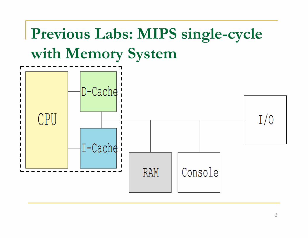
Previous Labs: MIPS single-cycle with Memory System
2
In this Lab: Pipelining
You are expected to:
Understand the concept
Be familiar with the 5 MIPS pipeline stages
Understand the three pipeline hazards and Understand the three pipeline hazards and their solutions.
3
PIPELINING
Technique in which the execution of severalinstructions is overlapped.
Each instruction is broken into several stages.
Stages can operate concurrently PROVIDEDWE HAVE SEPARATE RESOURCES FORWE HAVE SEPARATE RESOURCES FOREACH STAGE! => each step uses a differentfunctional unit.
Note: execution time for a single instruction isNOT improved. Throughput of severalinstructions is improved.
4
Major Pipeline Benefit = Performance
Ideal Performance
Time/instruction = non-piped-time/#stages
This is an asymptote of course, but +10% is commonly achieved
Two ways to view the performance mechanismTwo ways to view the performance mechanism
Reduced CPI (i.e. non-piped to piped change)
Close to 1 instruction/cycle if you’re lucky
Reduced cycle-time (i.e. increasing pipeline depth)
Work split into more stages
Simpler stages result in faster clock cycles
5
Other Pipeline Benefits
Completely hardware mechanism
All modern machines are pipelined
This was the key technique to advancingperformance in the 80’s
In the 90’s the move was to multiple In the 90’s the move was to multiplepipelines
Beware, no benefit is totally free/good
6
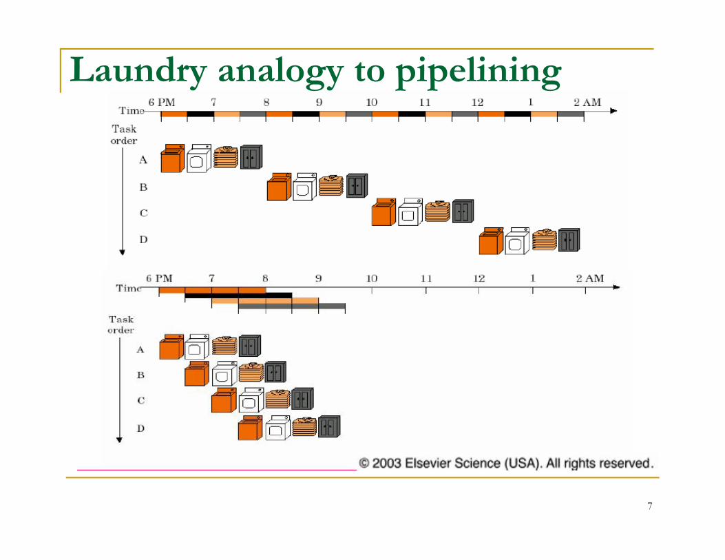
Laundry analogy to pipelining
7
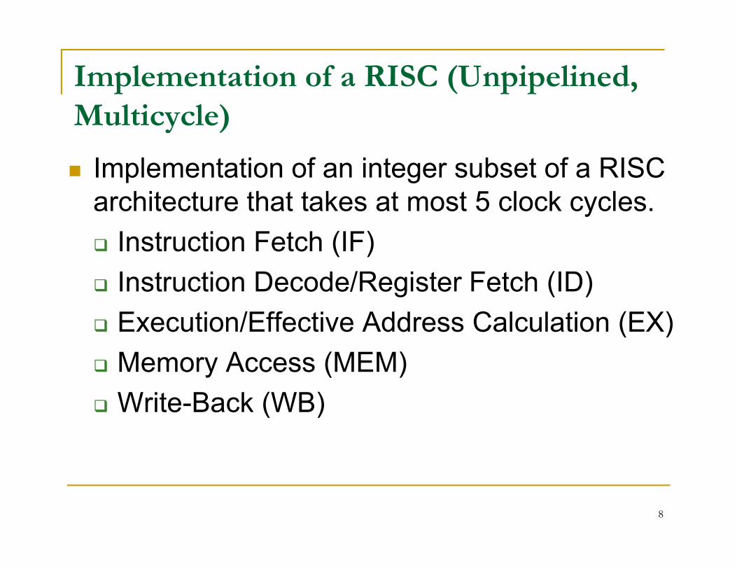
Implementation of a RISC (Unpipelined, Multicycle)
Implementation of an integer subset of a RISC architecture that takes at most 5 clock cycles.
Instruction Fetch (IF)
Instruction Decode/Register Fetch (ID) Instruction Decode/Register Fetch (ID)
Execution/Effective Address Calculation (EX)
Memory Access (MEM)
Write-Back (WB)
8
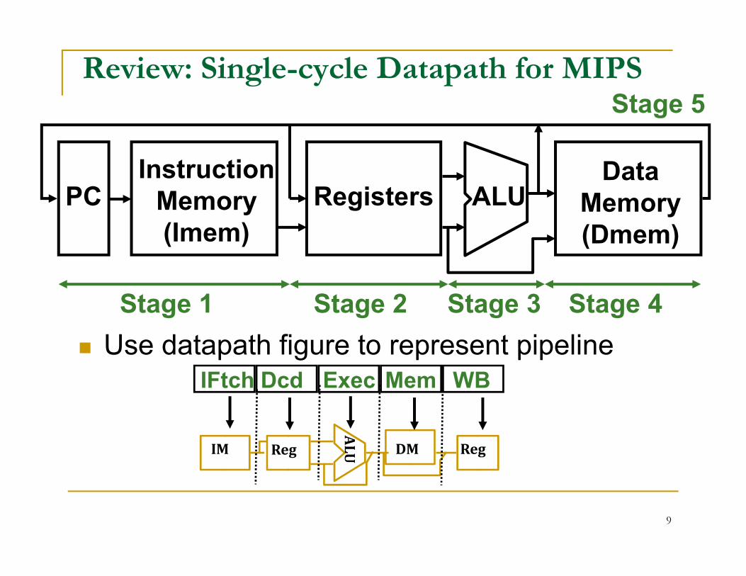
Review: Single-cycle Datapath for MIPS
DataMemory(Dmem)
PC Registers ALUInstruction
Memory(Imem)
Stage 5
Stage 1 Stage 2 Stage 3 Stage 4
IFtch Dcd Exec Mem WB
Use datapath figure to represent pipeline
ALUIM Reg DM Reg
9
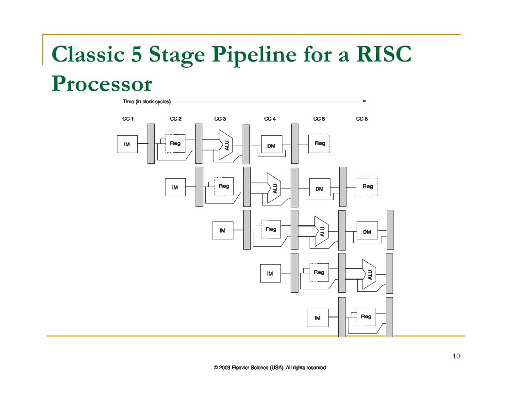
Classic 5 Stage Pipeline for a RISC Processor
10
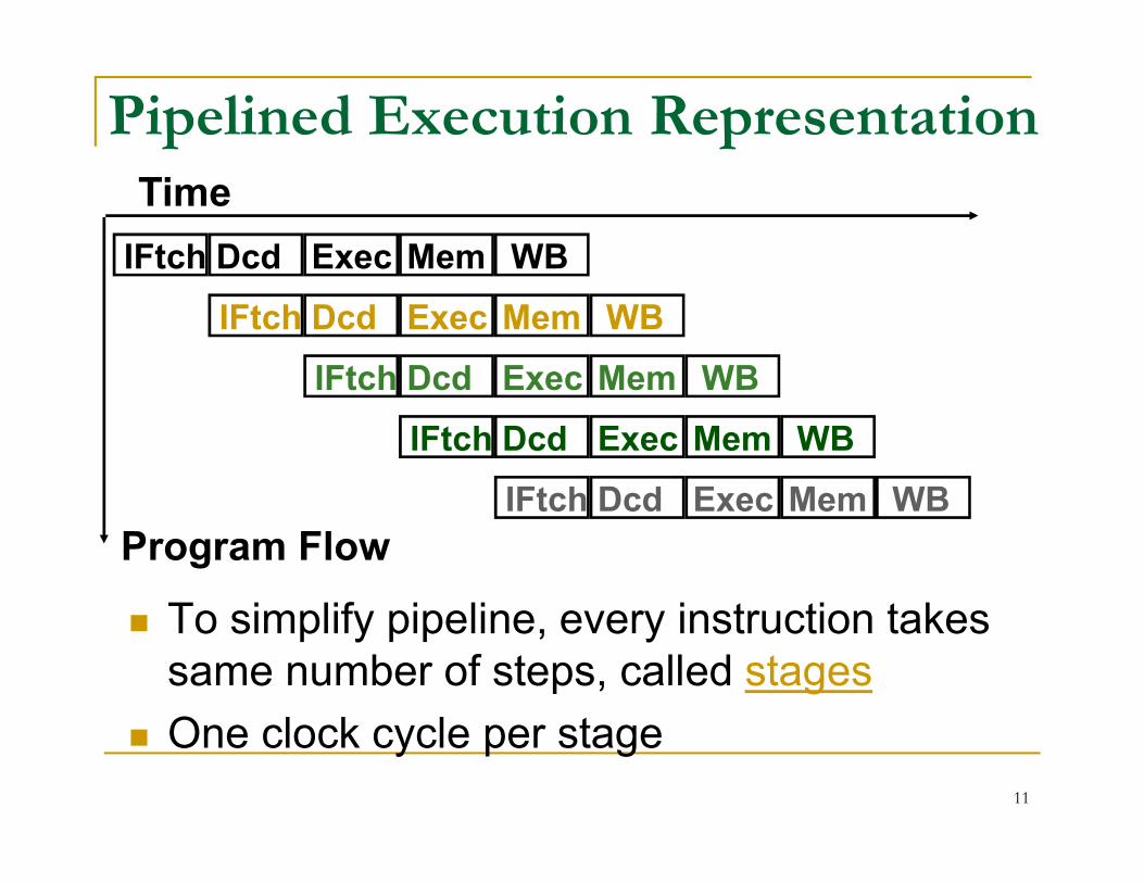
Pipelined Execution Representation
IFtch Dcd Exec Mem WB
IFtch Dcd Exec Mem WB
IFtch Dcd Exec Mem WB
IFtch Dcd Exec Mem WB
Time
To simplify pipeline, every instruction takes same number of steps, called stages
One clock cycle per stage
IFtch Dcd Exec Mem WB
IFtch Dcd Exec Mem WB
Program Flow
11
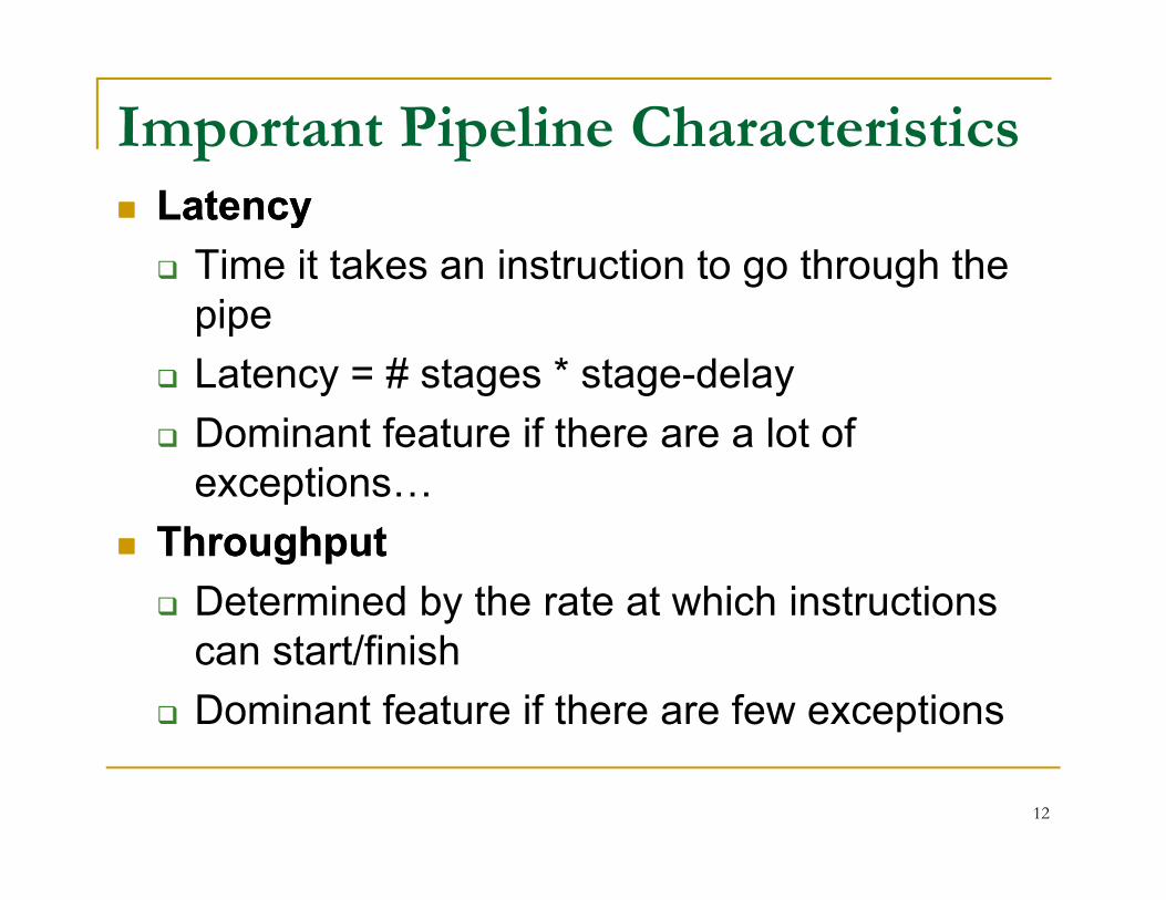
Important Pipeline Characteristics LatencyLatency
Time it takes an instruction to go through the pipe
Latency = # stages * stage-delay
Dominant feature if there are a lot of Dominant feature if there are a lot of exceptions…
ThroughputThroughput
Determined by the rate at which instructions can start/finish
Dominant feature if there are few exceptions
12
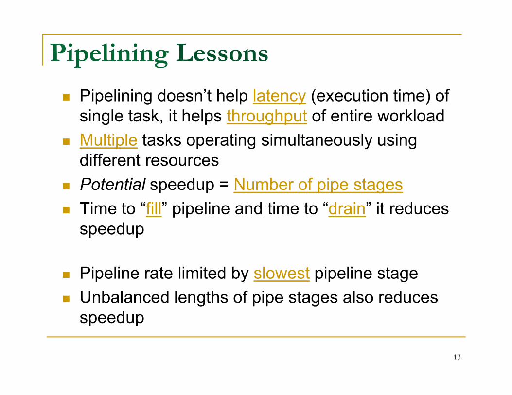
Pipelining Lessons
Pipelining doesn’t help latency (execution time) of single task, it helps throughput of entire workload
Multiple tasks operating simultaneously using different resources
Potential speedup = Number of pipe stages
Time to “fill” pipeline and time to “drain” it reduces speedup
Pipeline rate limited by slowest pipeline stage
Unbalanced lengths of pipe stages also reduces speedup
13
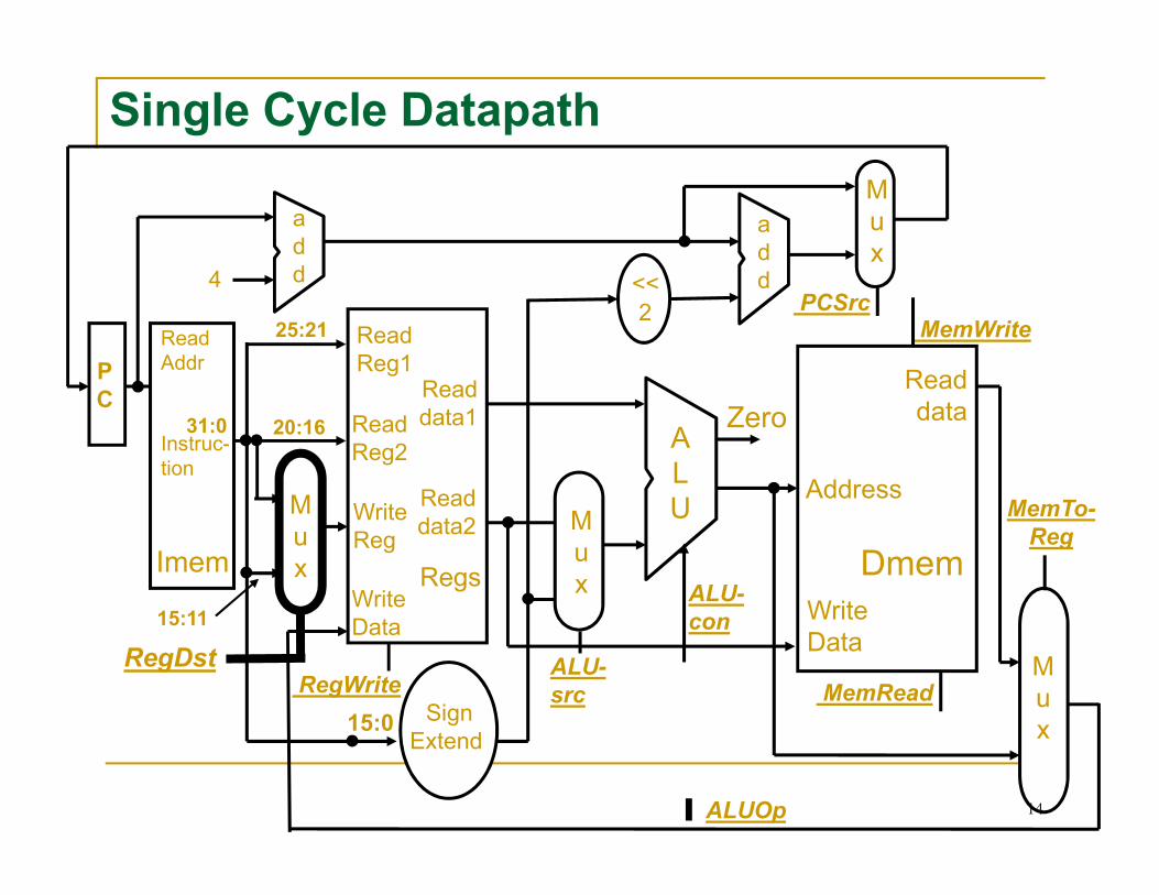
Single Cycle Datapath
ReadReg1
Readdata1
AReadReg2
Zero
Readdata
MemWriteRead Addr
Instruc-
4
PC
add
add<<
2
Mux
PCSrc25:21
20:1631:0
Regs
ALURead
data2
Reg2
WriteReg
WriteData
ALU-con
RegWrite
Address
WriteData
SignExtend
Dmem
MemReadMux
MemTo-Reg
Mux
Instruc-tion
Imem
ALUOp
ALU-src
Mux
15:11
RegDst
15:0
14
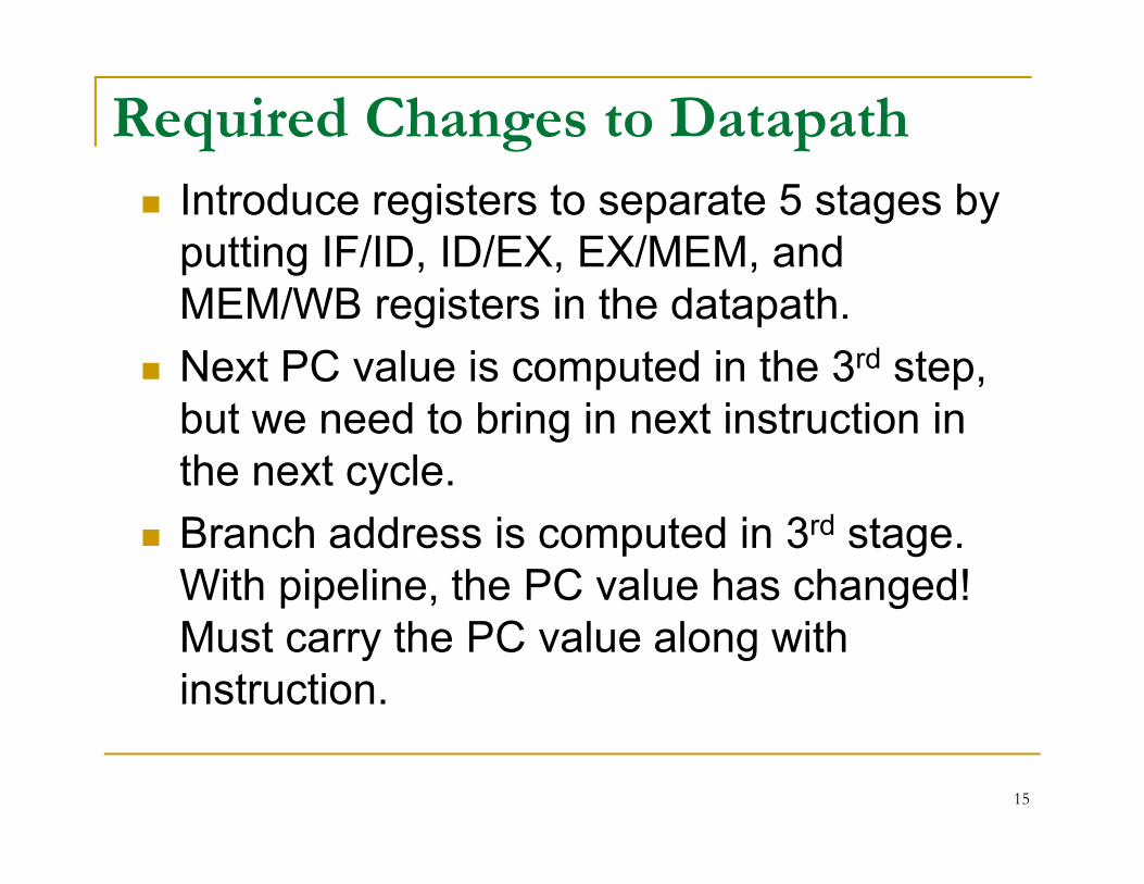
Required Changes to Datapath
Introduce registers to separate 5 stages by putting IF/ID, ID/EX, EX/MEM, and MEM/WB registers in the datapath.
Next PC value is computed in the 3rd step, but we need to bring in next instruction in but we need to bring in next instruction in the next cycle.
Branch address is computed in 3rd stage. With pipeline, the PC value has changed! Must carry the PC value along with instruction.
15
Changes to Datapath (cont.)
For lw instruction, we need write register address at stage 5. But the IR is now occupied by another instruction! So, we must carry the IR destination field as we move along the stages. See connection in move along the stages. See connection in fig.
16
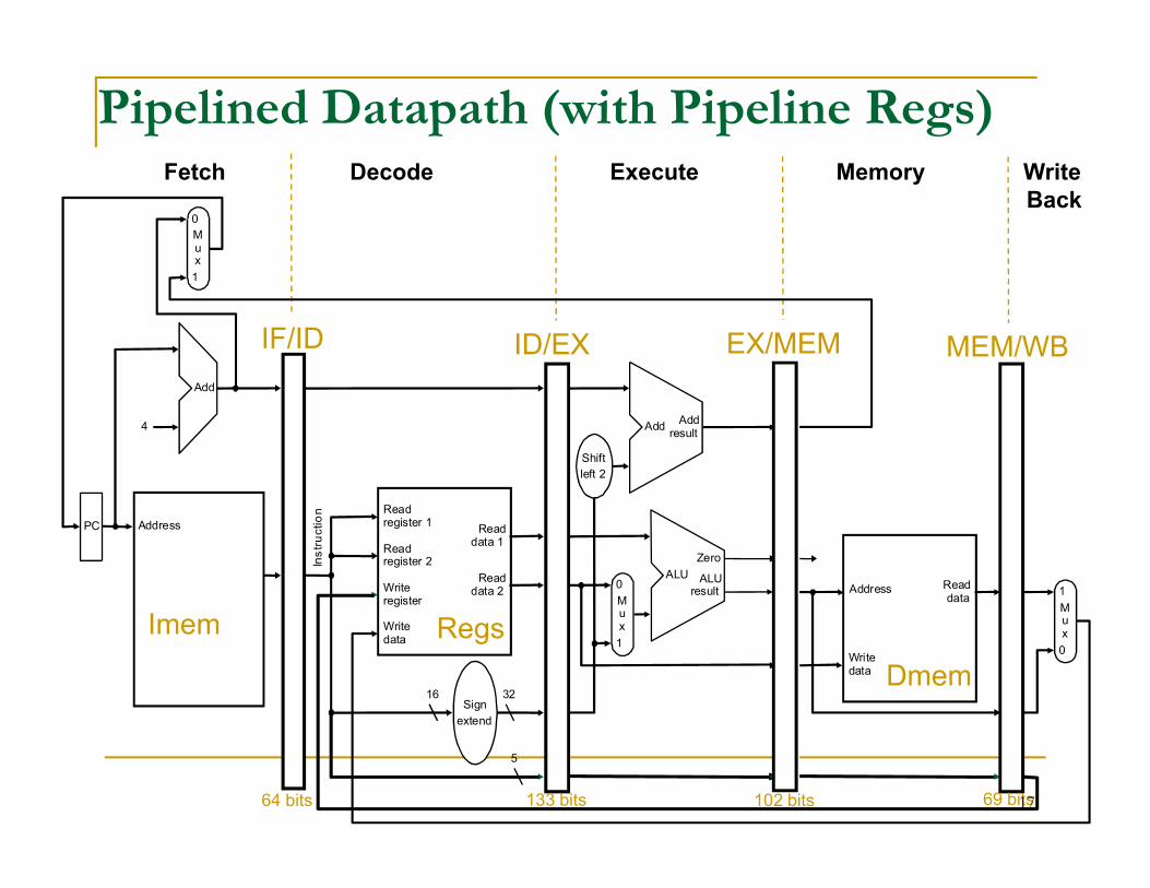
Pipelined Datapath (with Pipeline Regs)
4 AddAdd
result
Mux
0
1
Add
IF/ID ID/EX EX/MEM MEM/WB
Fetch Decode Execute Memory Write Back
Address
32
0
Shift
left 2
Ins
tru
ctio
n
PC
0
Address
Writedata
Mux
1
Readdata 1
Readdata 2
Readregister 1
Readregister 2
16Sign
extend
Writeregister
Writedata
Readdata
1
ALUresult
Mux
ALU
Zero
Imem
Dmem
Regs
64 bits 133 bits 102 bits 69 bits
5
17
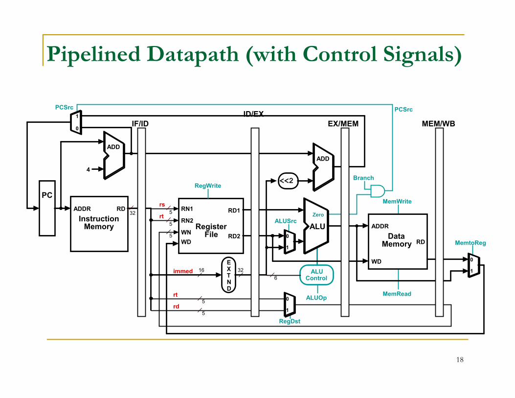
Pipelined Datapath (with Control Signals)
<<2
PC
4
ADD
ADD
IF/IDID/EX
EX/MEM MEM/WB
MemWrite
RegWrite
Branch
0
1
PCSrc PCSrc
MemtoReg5
RD1
RD2
RN1
RN2
WN
WD
RegisterFile
ALU
EXTND
16 32
RD
WD
DataMemory
ADDR
32RD
InstructionMemory
ADDR
PC
5
5
5
Zero
0
1
MemRead
ALUSrc
MemWrite
ALUControl6
ALUOp0
1
RegDst
5
rs
rt
rt
rd
immed
0
1
18
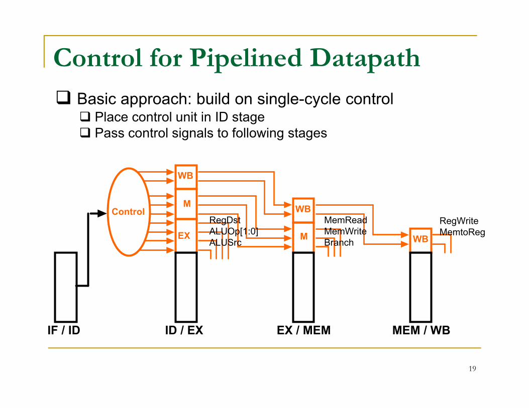
Control for Pipelined Datapath
M
WB
WB
Basic approach: build on single-cycle control Place control unit in ID stage Pass control signals to following stages
EX
MControl
IF / ID ID / EX EX / MEM MEM / WB
M
WB
WB
RegDstALUOp[1:0]ALUSrc
MemReadMemWriteBranch
RegWriteMemtoReg
19
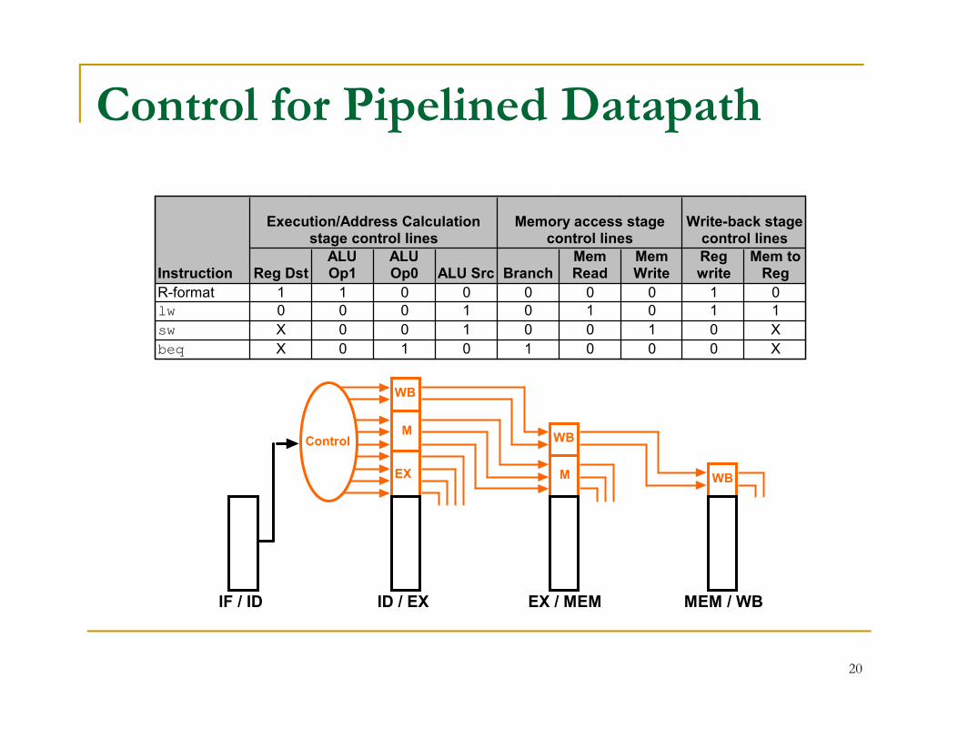
Control for Pipelined Datapath
Execution/Address Calculation stage control lines
Memory access stage control lines
Write-back stage control lines
Instruction Reg DstALU Op1
ALU Op0 ALU Src Branch
Mem Read
Mem Write
Reg write
Mem to Reg
R-format 1 1 0 0 0 0 0 1 0lw 0 0 0 1 0 1 0 1 1
sw X 0 0 1 0 0 1 0 X
beq X 0 1 0 1 0 0 0 X
EX
M
WB
Control
IF / ID ID / EX EX / MEM MEM / WB
M
WB
WB
20
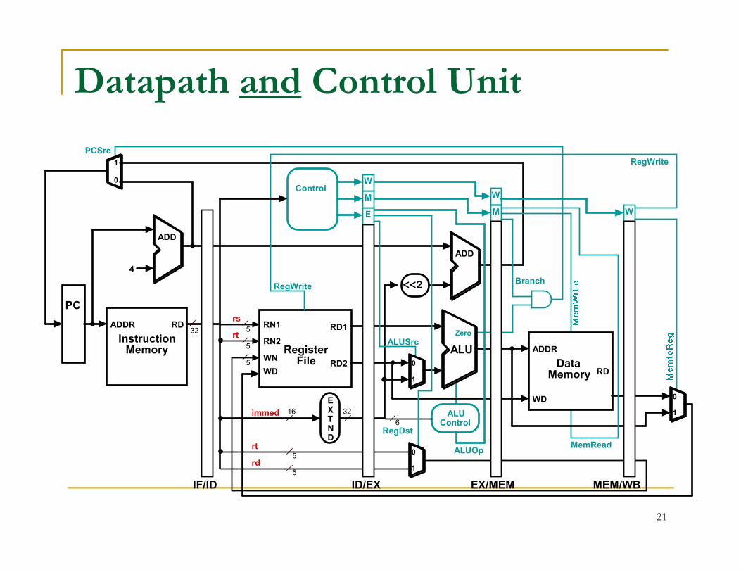
Datapath and Control Unit
W
M WE
<<2
4
ADD
ADD
RegWriteBranch
0
1
PCSrc
RegWrite
W
MControl
5
RD1
RD2
RN1
RN2
WN
WD
RegisterFile
ALU
EXTND
16 32
RD
WD
DataMemory
ADDR
32
<<2
RD
InstructionMemory
ADDR
PC
5
5
5
IF/ID ID/EX EX/MEM MEM/WB
Zero
0
1
MemRead
ALUSrc
ALUControl6
ALUOp0
1
RegDst
5
rs
rt
rt
rd
RegWrite
immed
Branch
0
1
21
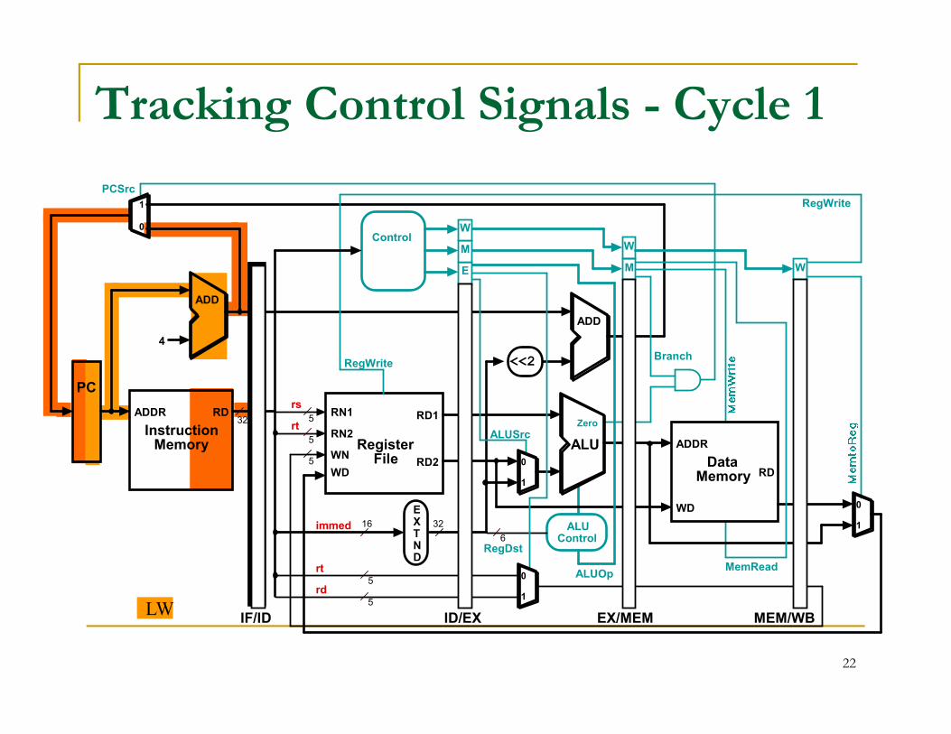
Tracking Control Signals - Cycle 1
W
M WE
<<2
4
ADD
ADD
RegWriteBranch
0
1
PCSrc
RegWrite
W
MControl
LW
5
RD1
RD2
RN1
RN2
WN
WD
RegisterFile
ALU
EXTND
16 32
RD
WD
DataMemory
ADDR
32
<<2
RD
InstructionMemory
ADDR
PC
5
5
5
IF/ID ID/EX EX/MEM MEM/WB
Zero
0
1
MemRead
ALUSrc
ALUControl6
ALUOp0
1
RegDst
5
rs
rt
rt
rd
RegWrite
immed
0
1
22
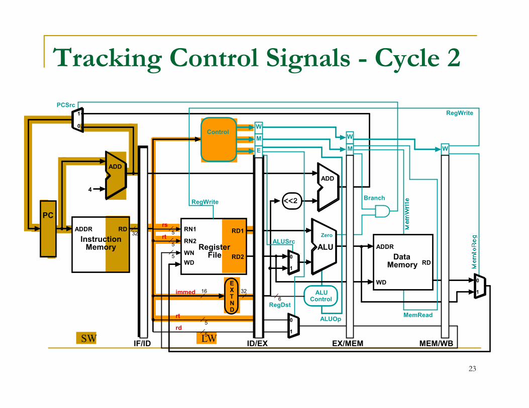
Tracking Control Signals - Cycle 2
W
M WE
<<2
4
ADD
ADD
RegWriteBranch
0
1
PCSrc
RegWrite
W
MControl
SW LW
5
RD1
RD2
RN1
RN2
WN
WD
RegisterFile
ALU
EXTND
16 32
RD
WD
DataMemory
ADDR
32
<<2
RD
InstructionMemory
ADDR
PC
5
5
5
IF/ID ID/EX EX/MEM MEM/WB
Zero
0
1
MemRead
ALUSrc
ALUControl6
ALUOp0
1
RegDst
5
rs
rt
rt
rd
RegWrite
immed
0
1
23
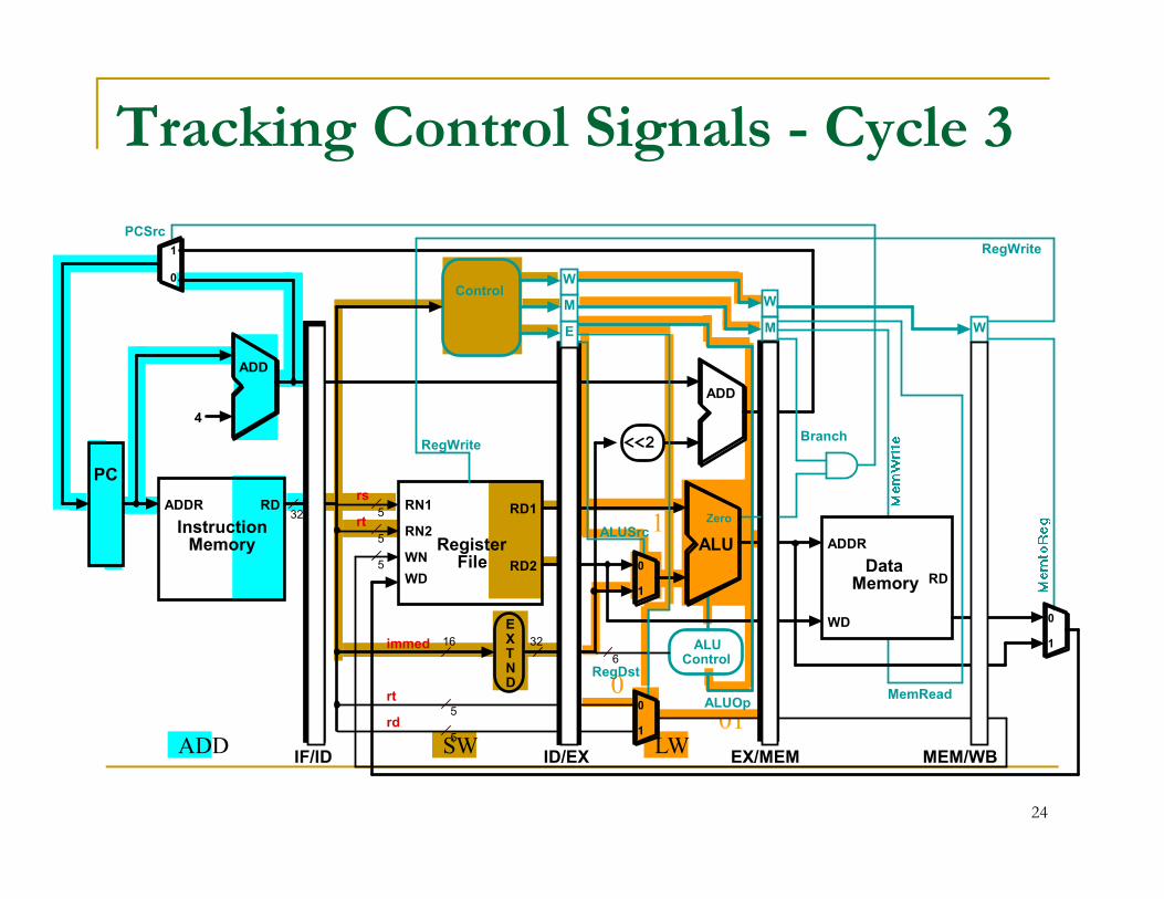
Tracking Control Signals - Cycle 3
W
M WE
<<2
4
ADD
ADD
RegWriteBranch
0
1
PCSrc
RegWrite
W
MControl
ADD SW LW
0
01
1
5
RD1
RD2
RN1
RN2
WN
WD
RegisterFile
ALU
EXTND
16 32
RD
WD
DataMemory
ADDR
32
<<2
RD
InstructionMemory
ADDR
PC
5
5
5
IF/ID ID/EX EX/MEM MEM/WB
Zero
0
1
MemRead
ALUSrc
ALUControl6
ALUOp0
1
RegDst
5
rs
rt
rt
rd
RegWrite
immed
0
1
24
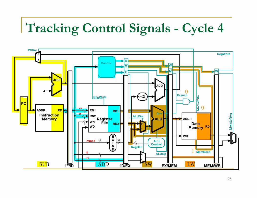
Tracking Control Signals - Cycle 4
0
W
M WE
<<2
4
ADD
ADD
RegWriteBranch
0
1
PCSrc
RegWrite
W
MControl
SUB ADD SW LW
1
0
5
RD1
RD2
RN1
RN2
WN
WD
RegisterFile
ALU
EXTND
16 32
RD
WD
DataMemory
ADDR
32RD
InstructionMemory
ADDR
PC
5
5
5
IF/ID ID/EX EX/MEM MEM/WB
Zero
0
1
MemRead
ALUSrc
ALUControl6
ALUOp0
1
RegDst
5
rs
rt
rt
rd
immed
0
1
25
1
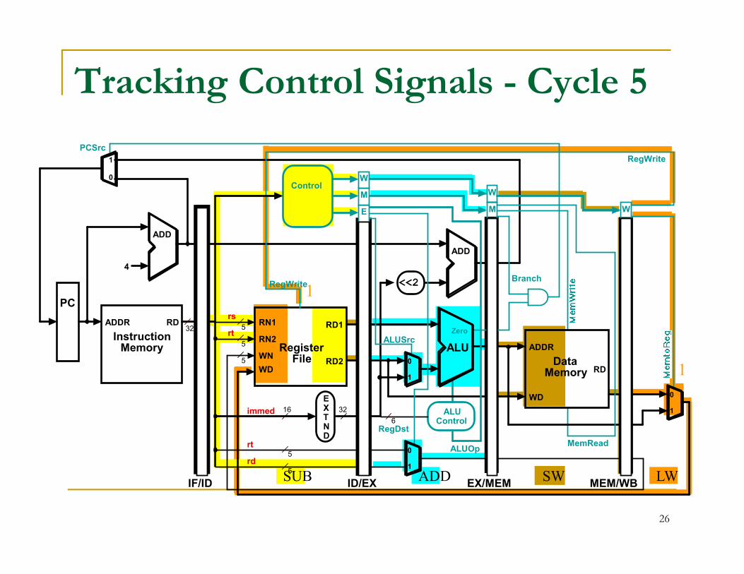
Tracking Control Signals - Cycle 5
W
M WE
<<2
4
ADD
ADD
RegWriteBranch
0
1
PCSrc
RegWrite
W
MControl
1
1
ADDSUB SW LW
5
RD1
RD2
RN1
RN2
WN
WD
RegisterFile
ALU
EXTND
16 32
RD
WD
DataMemory
ADDR
32
<<2
RD
InstructionMemory
ADDR
PC
5
5
5
IF/ID ID/EX EX/MEM MEM/WB
Zero
0
1
MemRead
ALUSrc
ALUControl6
ALUOp0
1
RegDst
5
rs
rt
rt
rd
RegWrite
immed
0
1
26
Can pipelining get us into trouble?
Yes: Pipeline Hazards
Hazards occur because data required for executing the current instruction may not be available.
Structural hazards: attempt to use the same resource two different ways at the same timeresource two different ways at the same time
Control hazards: attempt to make a decision before condition is evaluated
branch instructions
interrupts
27
Pipelining troubles (cont.)
Data hazards occur when an instruction needs register contents for an arithmetic/ logical/memory instruction, before they are ready.
instruction depends on result of prior instruction still in the pipelineinstruction still in the pipeline
Can always resolve hazards by waiting:
pipeline control must detect the hazard
take action (or delay action) to resolve hazards
28
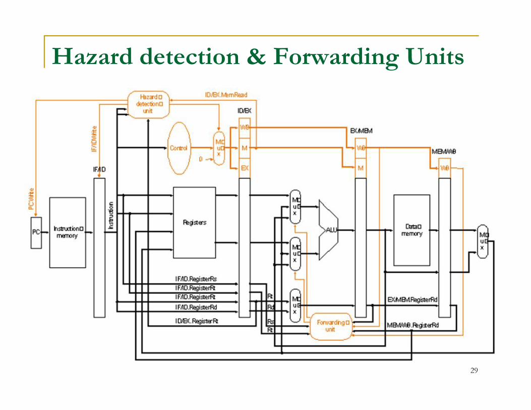
Hazard detection & Forwarding Units
29
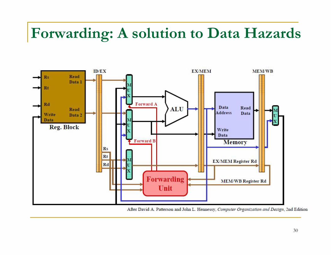
Forwarding: A solution to Data Hazards
30
Stalls Forwarding will not always solve the problems of data hazards.
For example, suppose an add instruction follows a load word (lw), andthe add involves the register that receives the memory data.
In this case, forwarding will not work.
The reason is that the data must be read from memory, and so it willnot be available until the end of the MEM cycle. Thus the required datais not available for a forward, and the add instruction. if it proceeds, willprocess the wrong data.
A solution to this problem is the stall.
A stall halts the instruction awaiting data, while the key instruction (a lwin this case) proceeds to the end of the MEM cycle, after which thedesired data is available to the add.
31
Other Problems With Branches
A remaining problem is what to do about instructions followinga branch.
Even assuming forwarding and stalls, the branch/no branchdecision is not made until the third stage.
This means that in the MIPS pipeline, two followinginstructions will enter the pipe before the branch/no branchdecision is made.decision is made.
What if: The following instructions were for the case of “branch taken” and the
branch was not taken.
The following instructions were for “branch not taken” and it was taken.
In either case, the wrong instructions are in the pipe and theymust be eliminated (“flushed”).
How can this problem be prevented?
32
Control Hazard Approach
One approach is to always assume the branch is(or is not)taken:
Say we assume the branch is never taken. Then if theinstruction in ALU/EX is a branch, the instructions in IF andID/RF will be those in the “not taken” program line (branchdetermination is made in ALU/EX).determination is made in ALU/EX).
It this assumption is correct, the pipeline will continue to flowwithout delay.
When the branch is taken, instructions in IF and ID/RF must be“flushed,” usually by changing the “op” code of those instructionsto a “nop” and letting them proceed to the end of the pipe.
33
Summary
Pipelining is a fundamental concept in computers/nature
Multiple instructions in flight
Limited by length of longest stage Limited by length of longest stage
Latency vs.Throughput
Hazards gum up the works
34


![CSIE30300 Computer Architecture Unit 04: Basic MIPS Pipelining Hsin-Chou Chi [Adapted from material by Patterson@UCB and Irwin@PSU]](https://img.dokumen.tips/doc/110x75/5697c0131a28abf838ccc889/csie30300-computer-architecture-unit-04-basic-mips-pipelining-hsin-chou-chi.jpg)