Embed Size (px)
Citation preview
Basic Pipelining & MIPS Pipelining
Chapter 6 [Computer Organization and Design, © 2007
Patterson (UCB) & Hennessy (Stanford),
& Slides Adapted from: Mary Jane Irwin (Penn State)]
• No Class Tuesday (Veterans Day)
• Midterms are not graded yet
• Grading for Course - Syllabus Doesn’t make sense. It says:
Midterm 35% 25% ?
Final 25% 30% ?
HW 20% 20% ?
Projects 20% 25% ?
________________________________________________________________________
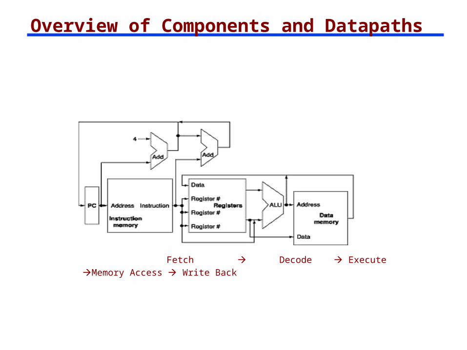
Overview of Components and Datapaths
Fetch Decode Execute Memory Access Write Back
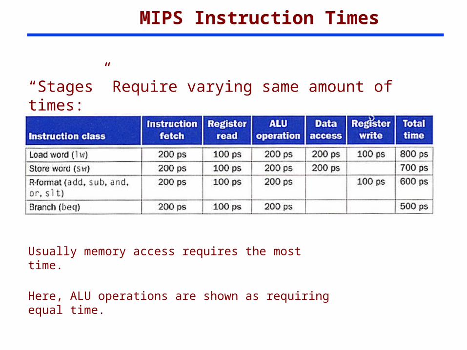
MIPS Instruction Times
“Stages” Require varying same amount of times:
Usually memory access requires the most time.
Here, ALU operations are shown as requiring equal time.
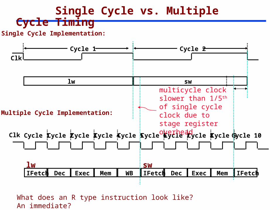
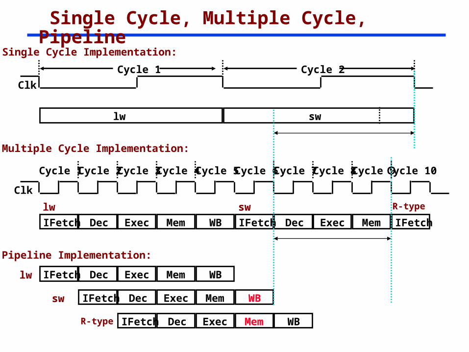
Single Cycle vs. Multiple Cycle Timing
Clk Cycle 1
Multiple Cycle Implementation:
IFetch Dec Exec Mem WB
Cycle 2 Cycle 3 Cycle 4 Cycle 5 Cycle 6 Cycle 7 Cycle 8 Cycle 9Cycle 10
IFetch Dec Exec Memlw sw
IFetch
Clk
Single Cycle Implementation:
lw sw
Cycle 1 Cycle 2
multicycle clock slower than 1/5th of single cycle clock due to stage register overhead
What does an R type instruction look like? An immediate?
How Can We Make It Even Faster?
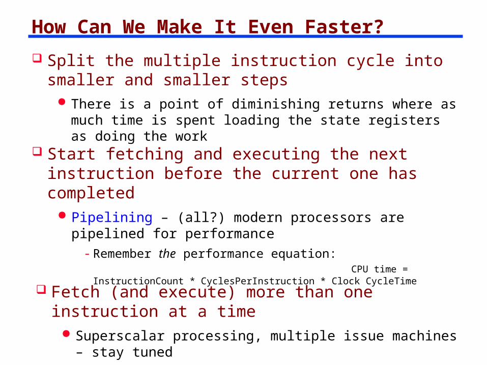
Split the multiple instruction cycle into smaller and smaller steps
There is a point of diminishing returns where as much time is spent loading the state registers as doing the work
Start fetching and executing the next instruction before the current one has completed
Pipelining – (all?) modern processors are pipelined for performance
- Remember the performance equation: CPU time = InstructionCount * CyclesPerInstruction * Clock CycleTime
Fetch (and execute) more than one instruction at a time
Superscalar processing, multiple issue machines – stay tuned
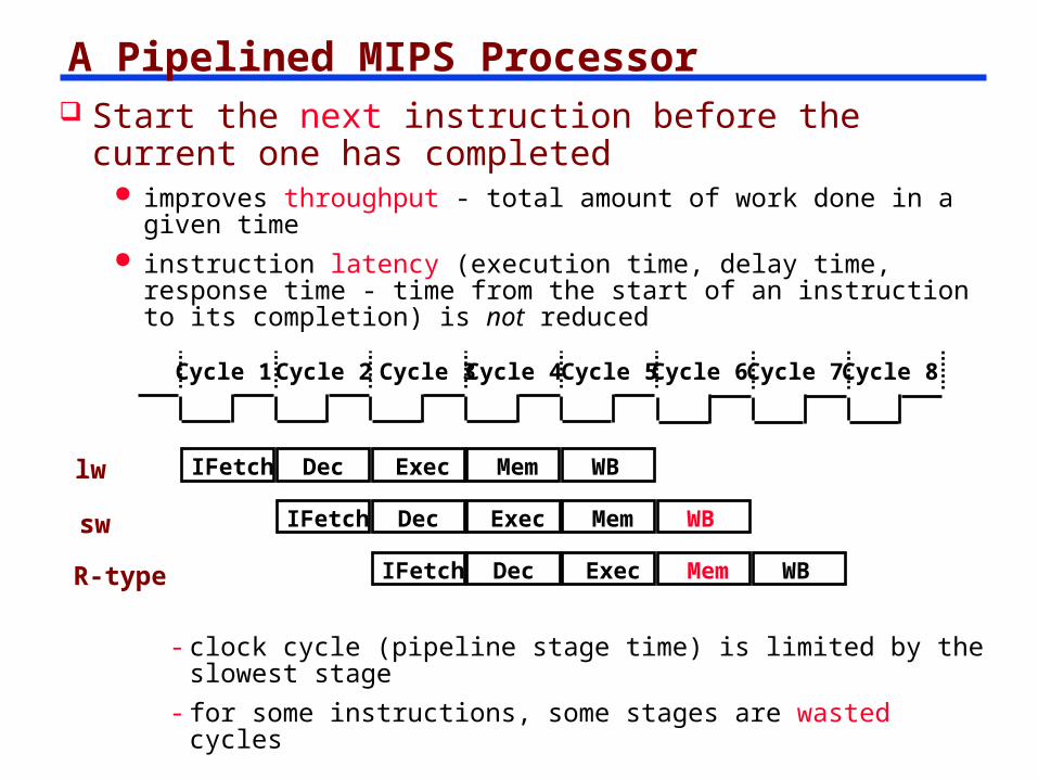
A Pipelined MIPS Processor Start the next instruction before the current one
has completed improves throughput - total amount of work done in a given
time instruction latency (execution time, delay time, response time -
time from the start of an instruction to its completion) is not reduced
Cycle 1 Cycle 2 Cycle 3 Cycle 4 Cycle 5
IFetch Dec Exec Mem WBlw
Cycle 7Cycle 6 Cycle 8
sw IFetch Dec Exec Mem WB
R-type IFetch Dec Exec Mem WB
- clock cycle (pipeline stage time) is limited by the slowest stage
- for some instructions, some stages are wasted cycles
Single Cycle, Multiple Cycle, Pipeline
Multiple Cycle Implementation:
Clk
Cycle 1
IFetch Dec Exec Mem WB
Cycle 2 Cycle 3 Cycle 4 Cycle 5 Cycle 6 Cycle 7 Cycle 8 Cycle 9Cycle 10
IFetch Dec Exec Mem
lw sw
IFetch
R-type
lw IFetch Dec Exec Mem WB
Pipeline Implementation:
IFetch Dec Exec Mem WBsw
IFetch Dec Exec Mem WBR-type
Clk
Single Cycle Implementation:
lw sw
Cycle 1 Cycle 2
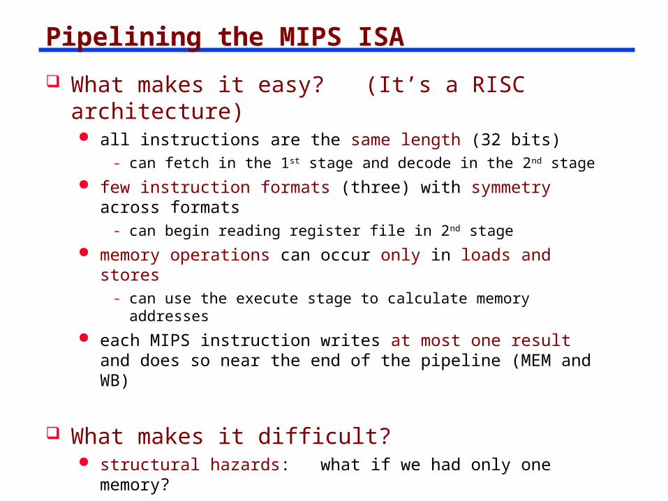
Pipelining the MIPS ISA
What makes it easy? (It’s a RISC architecture) all instructions are the same length (32 bits)
- can fetch in the 1st stage and decode in the 2nd stage few instruction formats (three) with symmetry across
formats- can begin reading register file in 2nd stage
memory operations can occur only in loads and stores- can use the execute stage to calculate memory addresses
each MIPS instruction writes at most one result and does so near the end of the pipeline (MEM and WB)
What makes it difficult? structural hazards: what if we had only one memory? control hazards: what about branches? data hazards: what if an instruction’s input operands
depend on the output of a previous instruction?
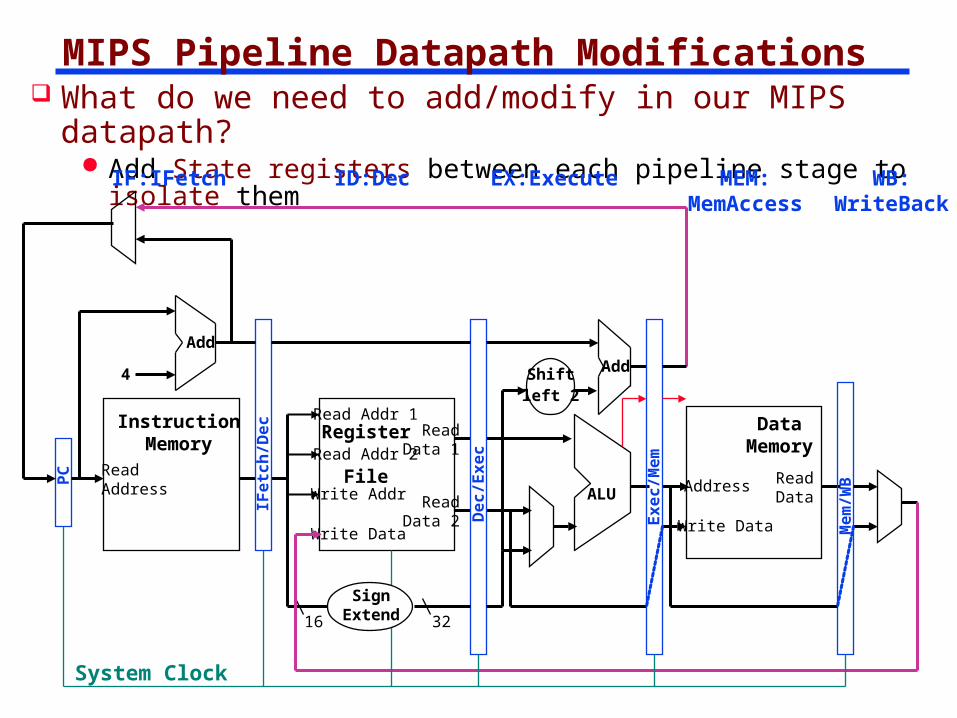
MIPS Pipeline Datapath Modifications What do we need to add/modify in our MIPS datapath?
Add State registers between each pipeline stage to isolate them
ReadAddress
InstructionMemory
Add
PC
4
Write Data
Read Addr 1
Read Addr 2
Write Addr
Register
File
Read Data 1
Read Data 2
16 32
ALU
Shiftleft 2
Add
DataMemory
Address
Write Data
ReadDataIF
etc
h/D
ec
De
c/E
xe
c
Ex
ec
/Me
m
Me
m/W
B
IF:IFetch ID:Dec EX:Execute MEM:MemAccess
WB:WriteBack
System Clock
SignExtend
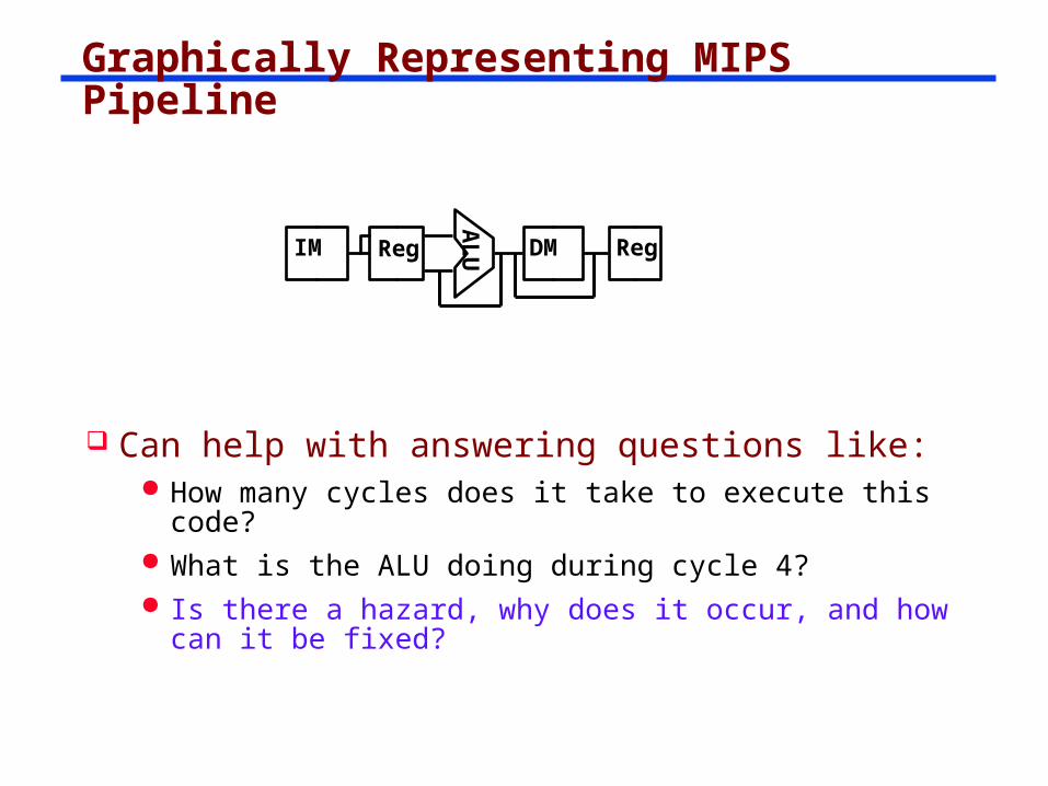
Graphically Representing MIPS Pipeline
Can help with answering questions like: How many cycles does it take to execute this code? What is the ALU doing during cycle 4? Is there a hazard, why does it occur, and how can it
be fixed?A
LUIM Reg DM Reg
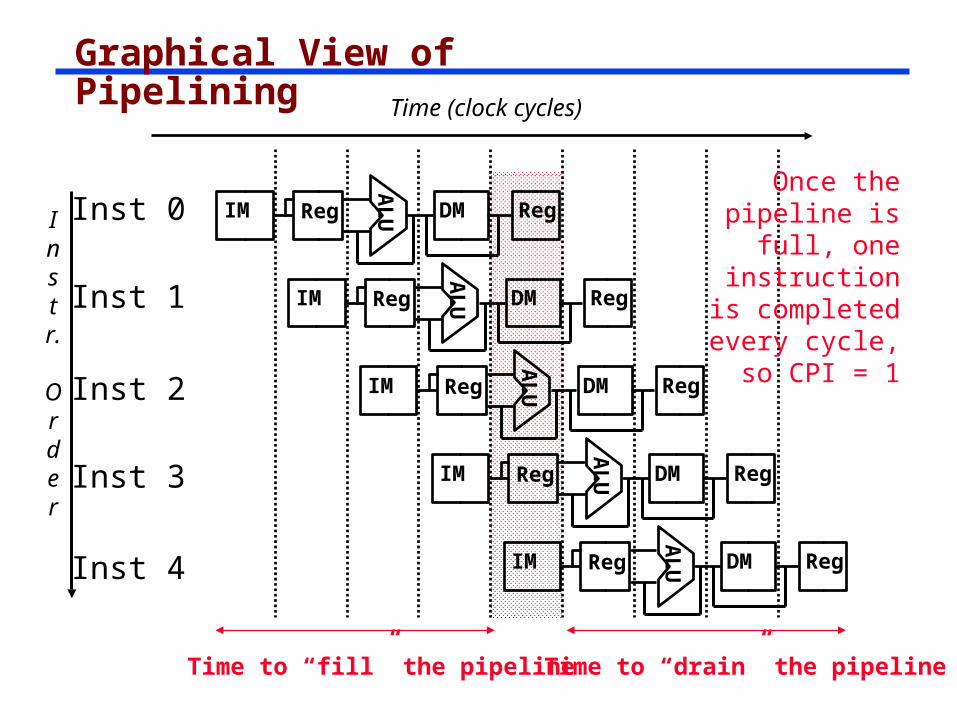
Graphical View of Pipelining
Instr.
Order
Time (clock cycles)
Inst 0
Inst 1
Inst 2
Inst 4
Inst 3
AL
UIM Reg DM Reg
AL
UIM Reg DM Reg
AL
UIM Reg DM RegA
LUIM Reg DM Reg
AL
UIM Reg DM Reg
Once the pipeline is full,
one instruction is
completed every cycle,
so CPI = 1
Time to “fill” the pipelineTime to “drain” the pipeline
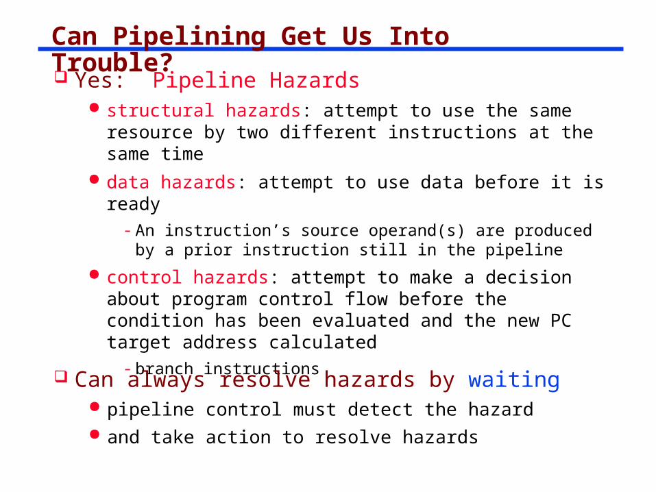
Can Pipelining Get Us Into Trouble? Yes: Pipeline Hazards
structural hazards: attempt to use the same resource by two different instructions at the same time
data hazards: attempt to use data before it is ready- An instruction’s source operand(s) are produced by a
prior instruction still in the pipeline
control hazards: attempt to make a decision about program control flow before the condition has been evaluated and the new PC target address calculated
- branch instructions
Can always resolve hazards by waiting pipeline control must detect the hazard and take action to resolve hazards
Instr.
Order
Time (clock cycles)
lw
Inst 1
Inst 2
Inst 4
Inst 3
AL
UMem Reg Mem Reg
AL
UMem Reg Mem Reg
AL
UMem Reg Mem RegA
LUMem Reg Mem Reg
AL
UMem Reg Mem Reg
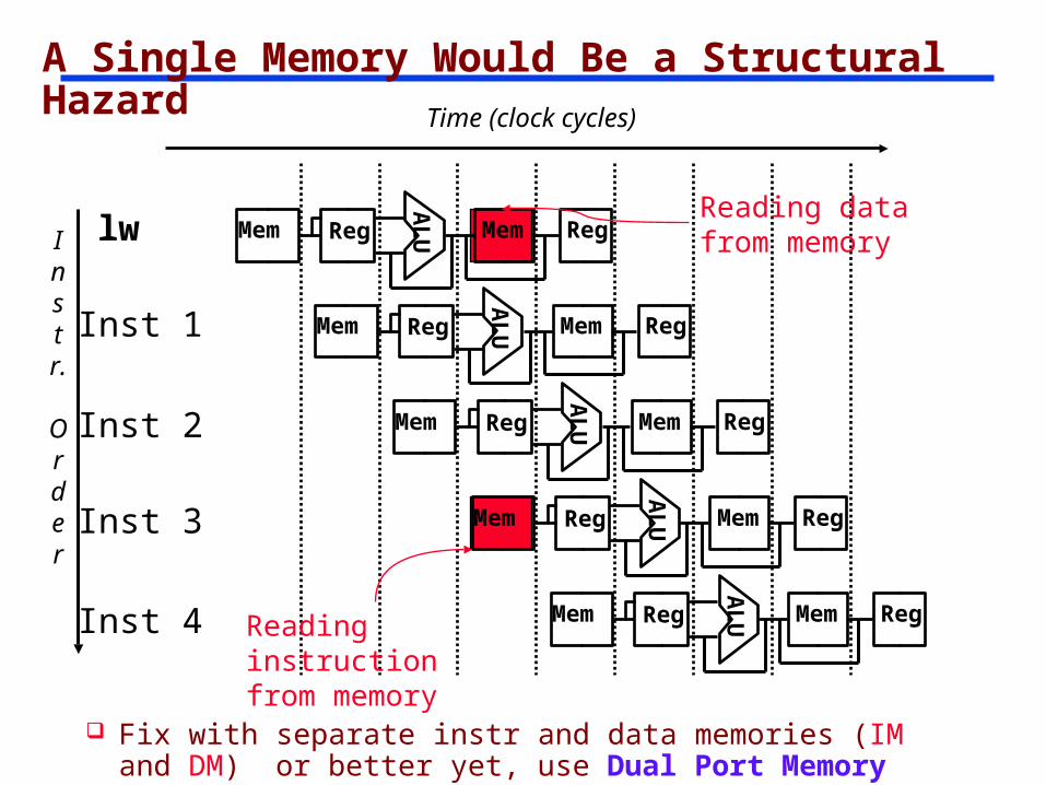
A Single Memory Would Be a Structural Hazard
Reading data from memory
Reading instruction from memory
Fix with separate instr and data memories (IM and DM) or better yet, use Dual Port Memory
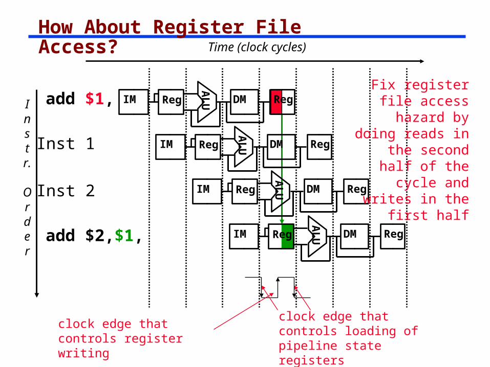
How About Register File Access?
Instr.
Order
Time (clock cycles)
Inst 1
Inst 2
AL
UIM Reg DM Reg
AL
UIM Reg DM Reg
AL
UIM Reg DM RegA
LUIM Reg DM Reg
Fix register file access hazard by
doing reads in the second half of the cycle and
writes in the first half
add $1,
add $2,$1,
clock edge that controls register writing
clock edge that controls loading of pipeline state registers
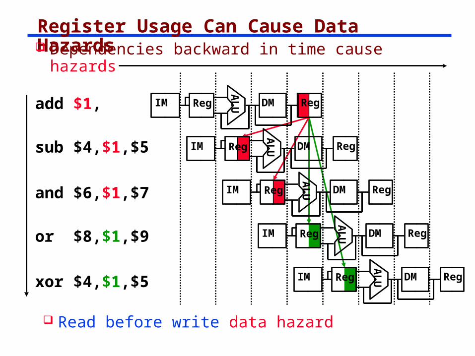
Register Usage Can Cause Data Hazards
AL
UIM Reg DM Reg
AL
UIM Reg DM Reg
AL
UIM Reg DM Reg
AL
UIM Reg DM Reg
AL
UIM Reg DM Reg
Dependencies backward in time cause hazards
add $1,
sub $4,$1,$5
and $6,$1,$7
xor $4,$1,$5
or $8,$1,$9
Read before write data hazard
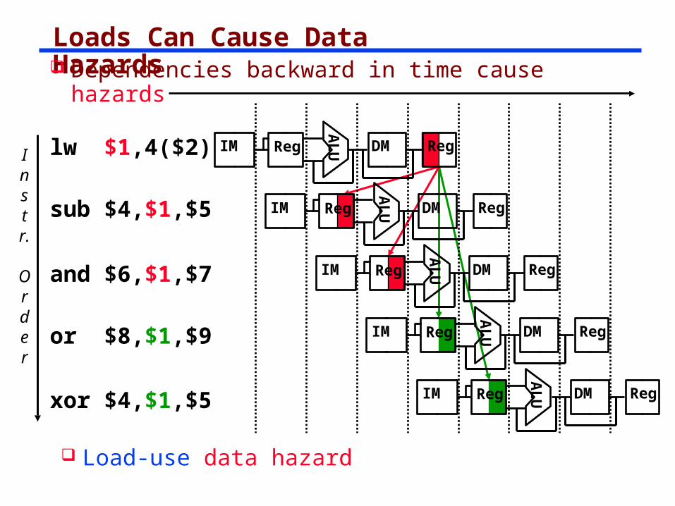
Loads Can Cause Data Hazards
Instr.
Order
lw $1,4($2)
sub $4,$1,$5
and $6,$1,$7
xor $4,$1,$5
or $8,$1,$9A
LUIM Reg DM Reg
AL
UIM Reg DM Reg
AL
UIM Reg DM Reg
AL
UIM Reg DM Reg
AL
UIM Reg DM Reg
Dependencies backward in time cause hazards
Load-use data hazard
stall
stall
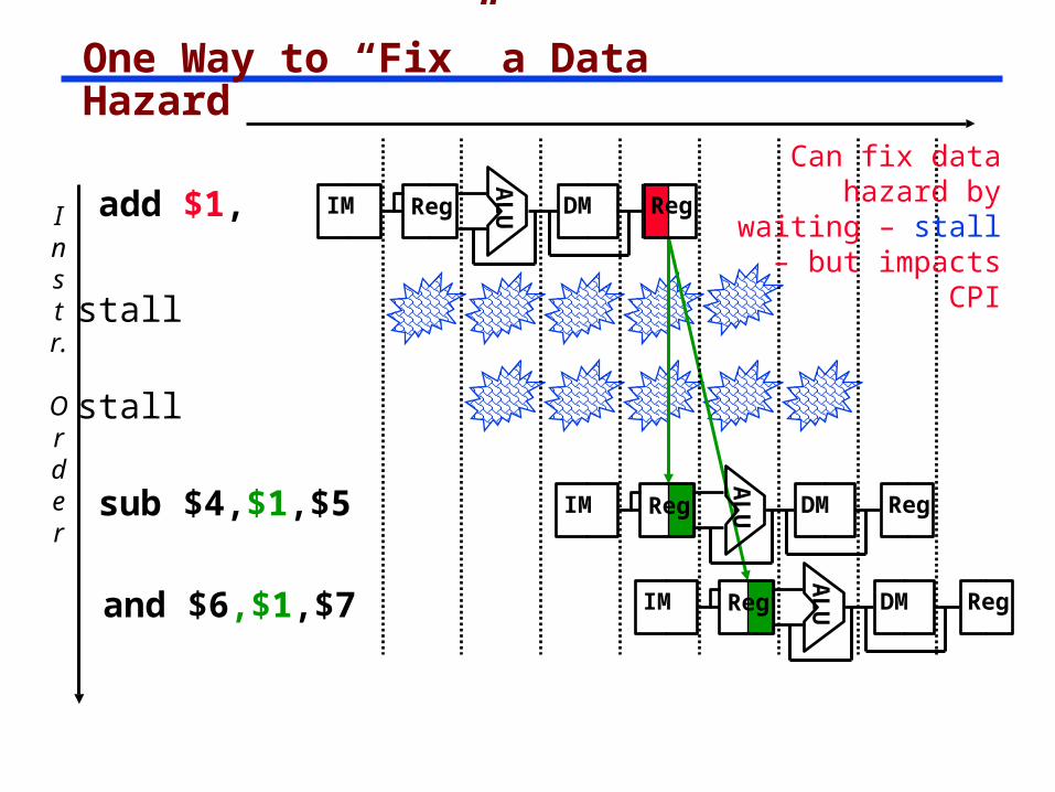
One Way to “Fix” a Data Hazard
Instr.
Order
add $1,
AL
UIM Reg DM Reg
sub $4,$1,$5
and $6,$1,$7
AL
UIM Reg DM Reg
AL
UIM Reg DM Reg
Can fix data hazard by waiting
– stall – but impacts CPI
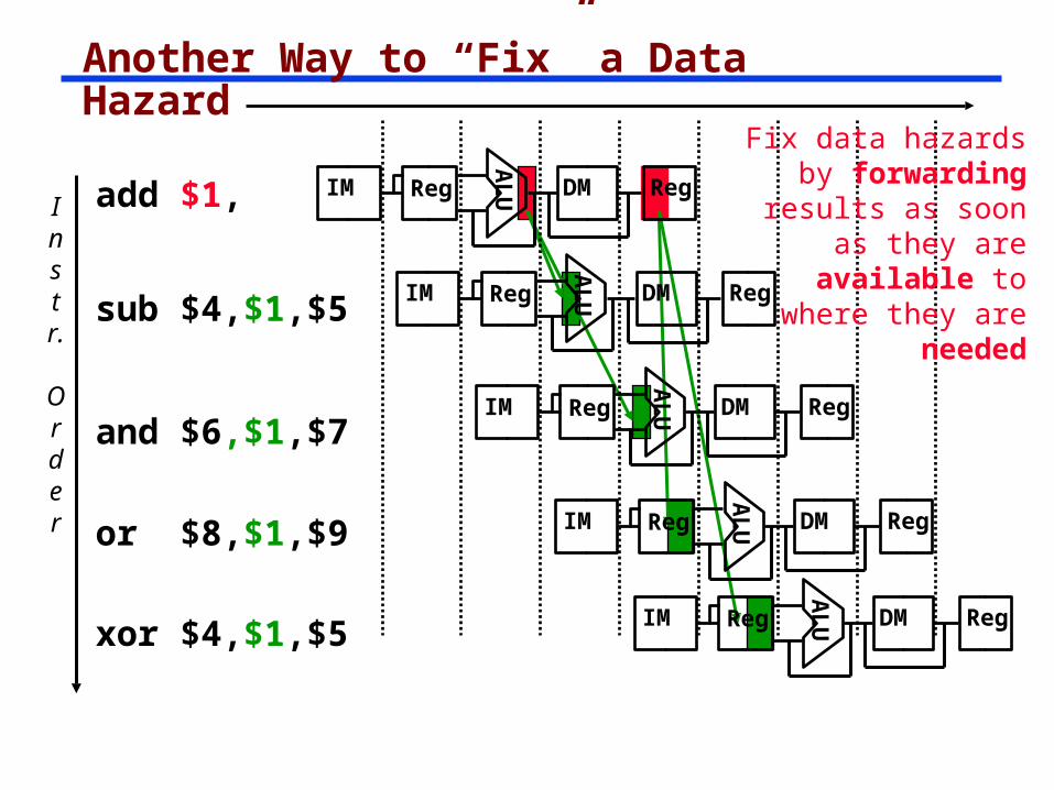
Another Way to “Fix” a Data Hazard
AL
UIM Reg DM Reg
AL
UIM Reg DM Reg
AL
UIM Reg DM Reg
Fix data hazards by forwarding results as soon as they are available to where
they are neededA
LUIM Reg DM Reg
AL
UIM Reg DM Reg
Instr.
Order
add $1,
sub $4,$1,$5
and $6,$1,$7
xor $4,$1,$5
or $8,$1,$9
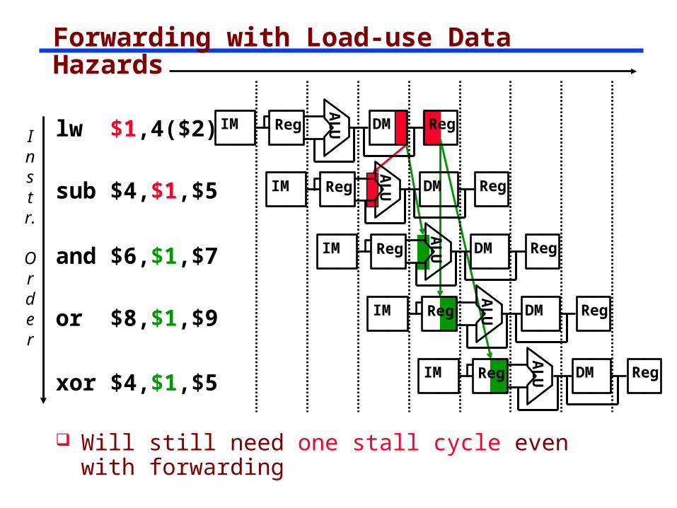
Forwarding with Load-use Data Hazards
AL
UIM Reg DM Reg
AL
UIM Reg DM Reg
AL
UIM Reg DM Reg
AL
UIM Reg DM Reg
AL
UIM Reg DM Reg
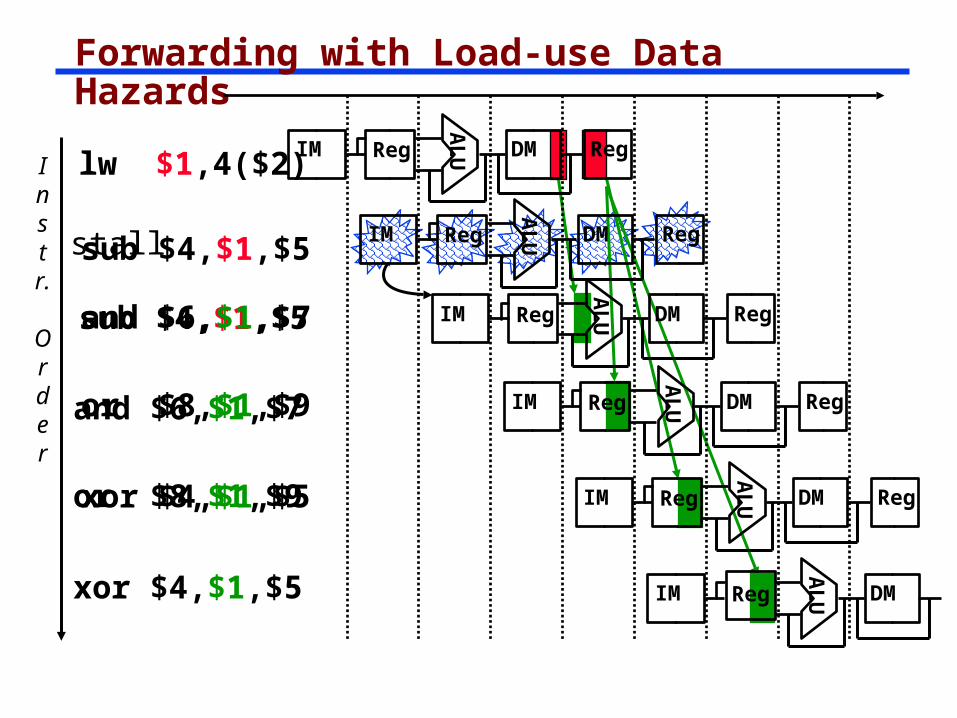
Will still need one stall cycle even with forwarding
Instr.
Order
lw $1,4($2)
sub $4,$1,$5
and $6,$1,$7
xor $4,$1,$5
or $8,$1,$9
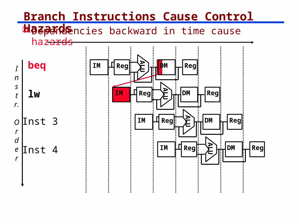
Branch Instructions Cause Control Hazards
Instr.
Order
lw
Inst 4
Inst 3
beq
AL
UIM Reg DM Reg
AL
UIM Reg DM Reg
AL
UIM Reg DM Reg
AL
UIM Reg DM Reg
Dependencies backward in time cause hazards
stall
stall
stall
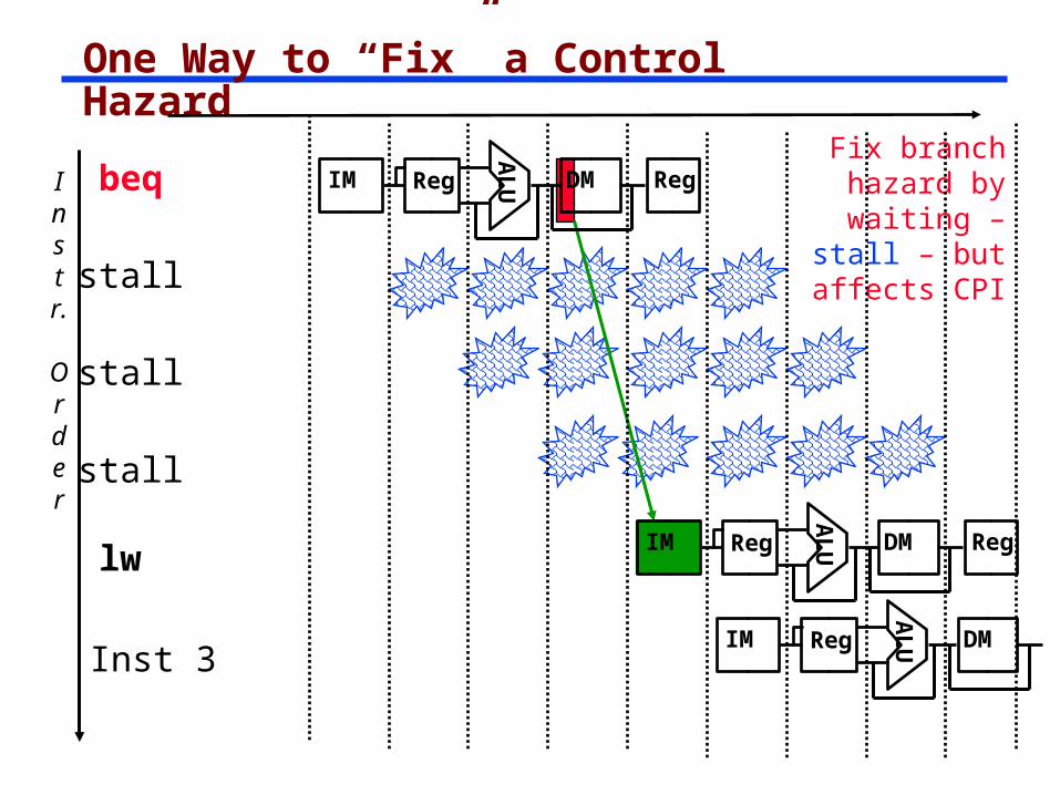
One Way to “Fix” a Control Hazard
Instr.
Order
beq
AL
UIM Reg DM Reg
lw
AL
UIM Reg DM Reg
AL
U
Inst 3IM Reg DM
Fix branch hazard by
waiting – stall – but affects CPI
We Have a Several Problems to Resolve YetWrite Back Challenge
The Write Back to a register requires that we know the destination register. We have lost that information!
The solution is to carry the destination address (5 bits) forward in the pipeline registers.
Control Signal Availability
The Control signals are determined in the Decode stage.
How do we get them to the Stages where they are used?
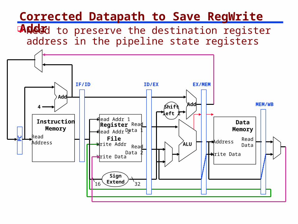
Corrected Datapath to Save RegWrite Addr Need to preserve the destination register
address in the pipeline state registers
ReadAddress
InstructionMemory
Add
PC
4
Write Data
Read Addr 1
Read Addr 2
Write Addr
Register
File
Read Data 1
Read Data 2
16 32
ALU
Shiftleft 2
Add
DataMemory
Address
Write Data
ReadData
IF/ID
SignExtend
ID/EX EX/MEM
MEM/WB
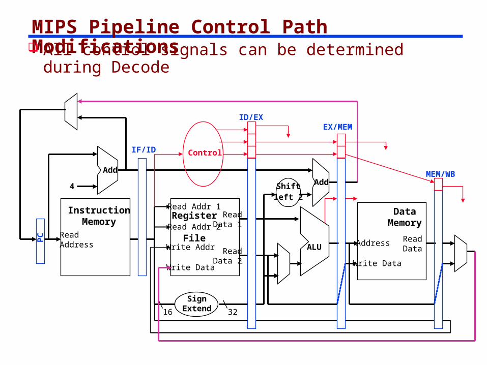
MIPS Pipeline Control Path Modifications All control signals can be determined during
Decode
ReadAddress
InstructionMemory
Add
PC
4
Write Data
Read Addr 1
Read Addr 2
Write Addr
Register
File
Read Data 1
Read Data 2
16 32
ALU
Shiftleft 2
Add
DataMemory
Address
Write Data
ReadData
IF/ID
SignExtend
ID/EXEX/MEM
MEM/WB
Control
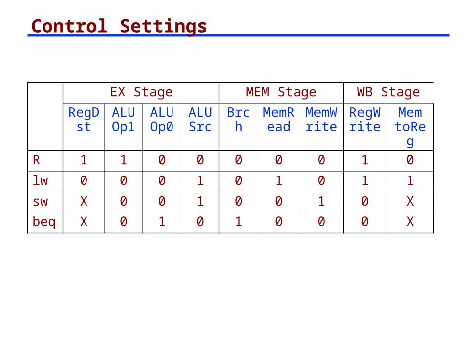
Control Settings
EX Stage MEM Stage WB Stage
RegDst
ALUOp1
ALUOp0
ALUSrc
Brch
MemRea
d
MemWrit
e
RegWrit
e
Mem toRe
gR 1 1 0 0 0 0 0 1 0
lw 0 0 0 1 0 1 0 1 1
sw X 0 0 1 0 0 1 0 X
beq X 0 1 0 1 0 0 0 X
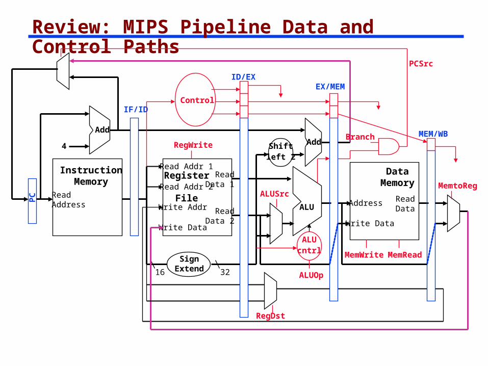
Review: MIPS Pipeline Data and Control Paths
ReadAddress
InstructionMemory
Add
PC
4
Write Data
Read Addr 1
Read Addr 2
Write Addr
Register
File
Read Data 1
Read Data 2
16 32
ALU
Shiftleft 2
Add
DataMemory
Address
Write Data
ReadData
IF/ID
SignExtend
ID/EXEX/MEM
MEM/WB
Control
ALUcntrl
RegWrite
MemWrite MemRead
MemtoReg
RegDst
ALUOp
ALUSrc
Branch
PCSrc
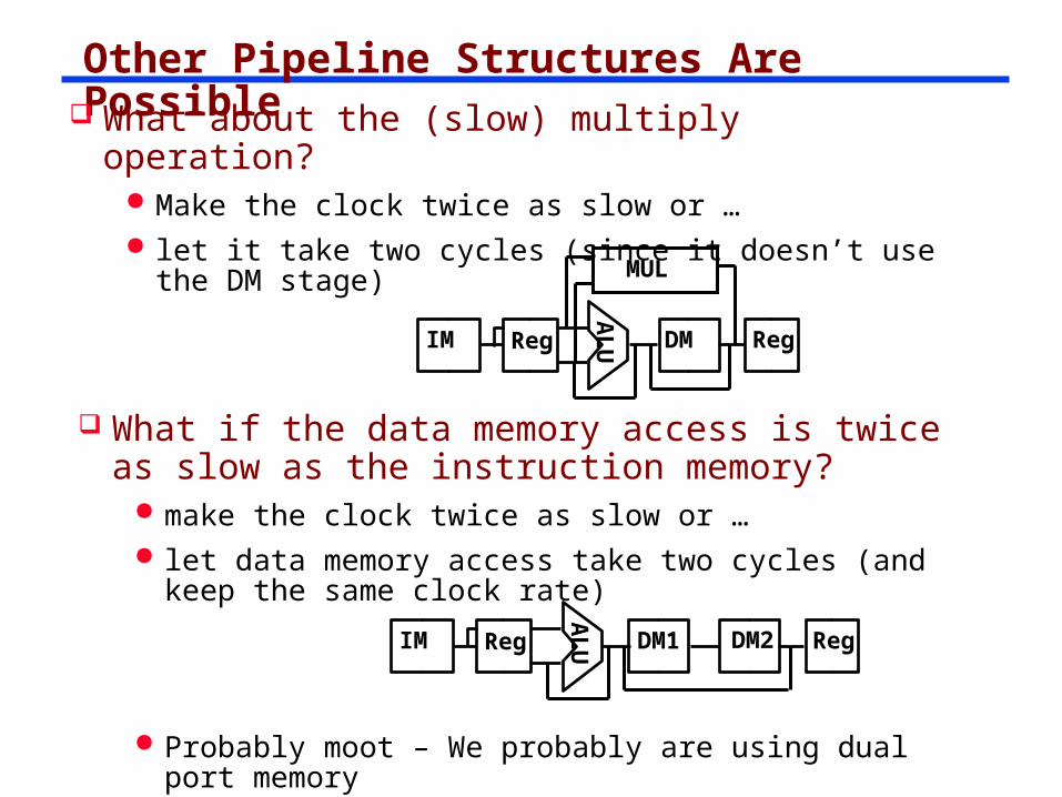
Other Pipeline Structures Are Possible What about the (slow) multiply operation?
Make the clock twice as slow or … let it take two cycles (since it doesn’t use the DM
stage)
AL
UIM Reg DM Reg
MUL
AL
UIM Reg DM1 RegDM2
What if the data memory access is twice as slow as the instruction memory?
make the clock twice as slow or … let data memory access take two cycles (and keep the
same clock rate)
Probably moot – We probably are using dual port memory
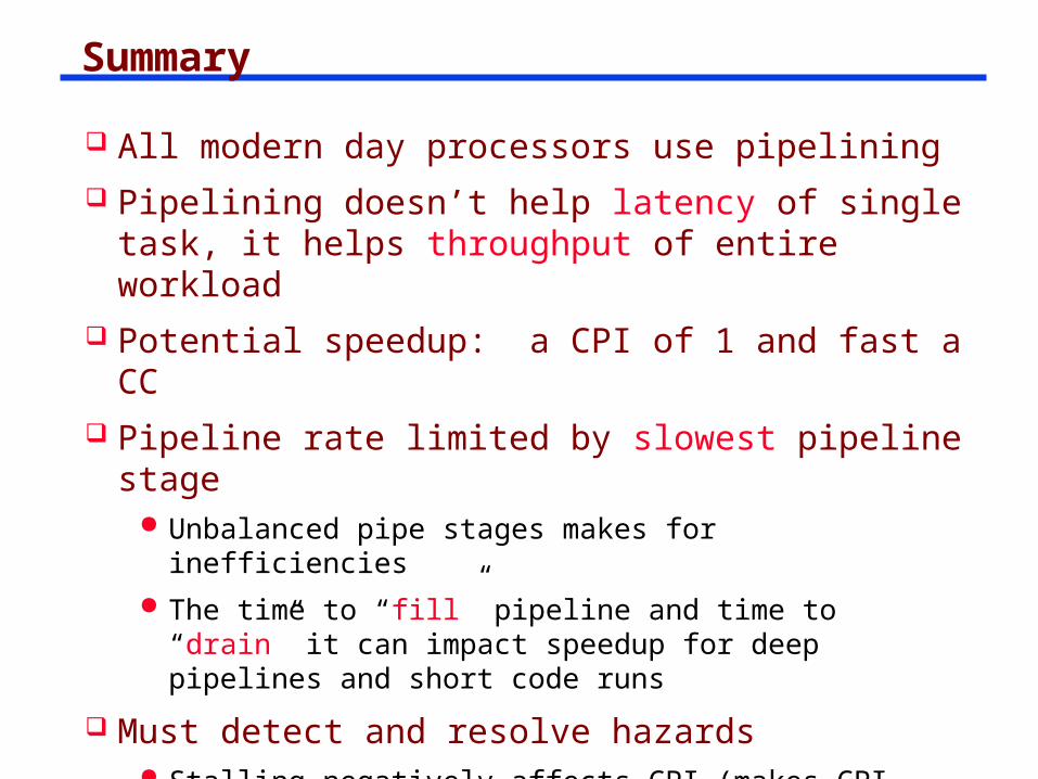
Summary All modern day processors use pipelining Pipelining doesn’t help latency of single task, it
helps throughput of entire workload Potential speedup: a CPI of 1 and fast a CC Pipeline rate limited by slowest pipeline stage
Unbalanced pipe stages makes for inefficiencies The time to “fill” pipeline and time to “drain” it can
impact speedup for deep pipelines and short code runs
Must detect and resolve hazards Stalling negatively affects CPI (makes CPI higher than
the ideal of 1)
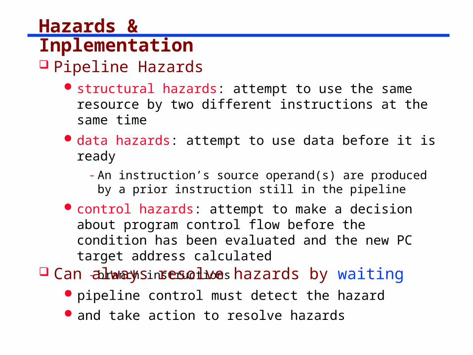
Hazards & Inplementation Pipeline Hazards
structural hazards: attempt to use the same resource by two different instructions at the same time
data hazards: attempt to use data before it is ready- An instruction’s source operand(s) are produced by a
prior instruction still in the pipeline
control hazards: attempt to make a decision about program control flow before the condition has been evaluated and the new PC target address calculated
- branch instructions
Can always resolve hazards by waiting pipeline control must detect the hazard and take action to resolve hazards
stall
stall
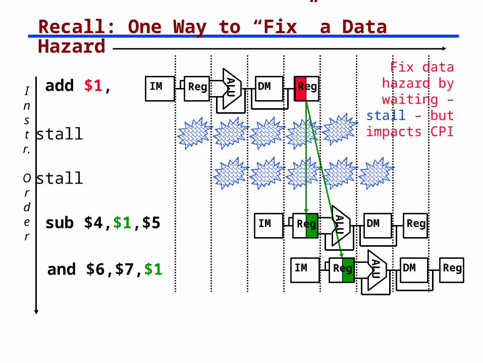
Recall: One Way to “Fix” a Data Hazard
Instr.
Order
add $1,
AL
UIM Reg DM Reg
sub $4,$1,$5
and $6,$7,$1
AL
UIM Reg DM Reg
AL
UIM Reg DM Reg
Fix data hazard by waiting – stall – but impacts CPI
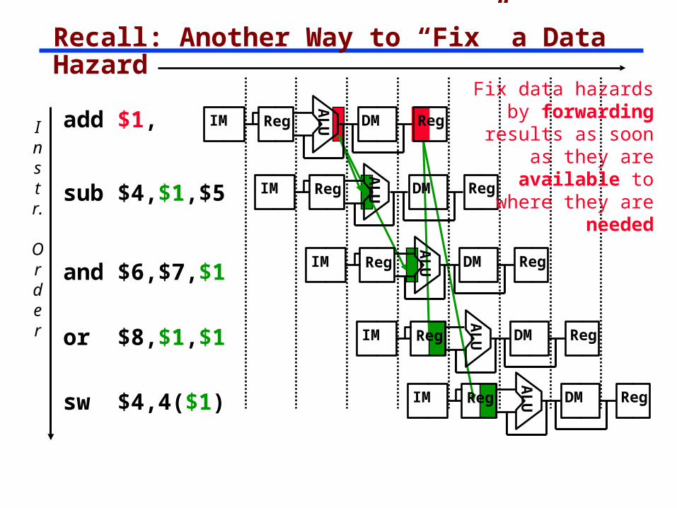
Recall: Another Way to “Fix” a Data Hazard
Instr.
Order
add $1,
AL
UIM Reg DM Reg
sub $4,$1,$5
and $6,$7,$1A
LUIM Reg DM Reg
AL
UIM Reg DM Reg
Fix data hazards by forwarding results as soon as they are available to where
they are needed
sw $4,4($1)
or $8,$1,$1
AL
UIM Reg DM Reg
AL
UIM Reg DM Reg
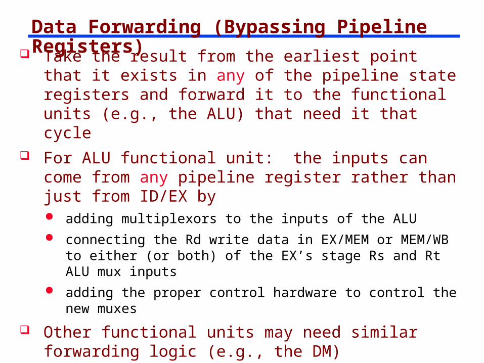
Data Forwarding (Bypassing Pipeline Registers) Take the result from the earliest point that it exists
in any of the pipeline state registers and forward it to the functional units (e.g., the ALU) that need it that cycle
For ALU functional unit: the inputs can come from any pipeline register rather than just from ID/EX by adding multiplexors to the inputs of the ALU connecting the Rd write data in EX/MEM or MEM/WB to
either (or both) of the EX’s stage Rs and Rt ALU mux inputs
adding the proper control hardware to control the new muxes
Other functional units may need similar forwarding logic (e.g., the DM)
With forwarding can achieve a CPI of 1 even in the presence of data dependencies
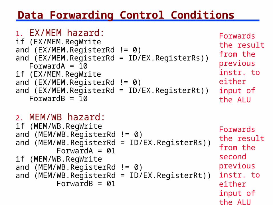
Data Forwarding Control Conditions
1. EX/MEM hazard: if (EX/MEM.RegWriteand (EX/MEM.RegisterRd != 0)and (EX/MEM.RegisterRd = ID/EX.RegisterRs))
ForwardA = 10if (EX/MEM.RegWriteand (EX/MEM.RegisterRd != 0)and (EX/MEM.RegisterRd = ID/EX.RegisterRt))
ForwardB = 10
Forwards the result from the previous instr. to either input of the ALU
Forwards the result from the second previous instr. to either input of the ALU
2. MEM/WB hazard:if (MEM/WB.RegWriteand (MEM/WB.RegisterRd != 0)and (MEM/WB.RegisterRd = ID/EX.RegisterRs))
ForwardA = 01if (MEM/WB.RegWriteand (MEM/WB.RegisterRd != 0)and (MEM/WB.RegisterRd = ID/EX.RegisterRt))
ForwardB = 01
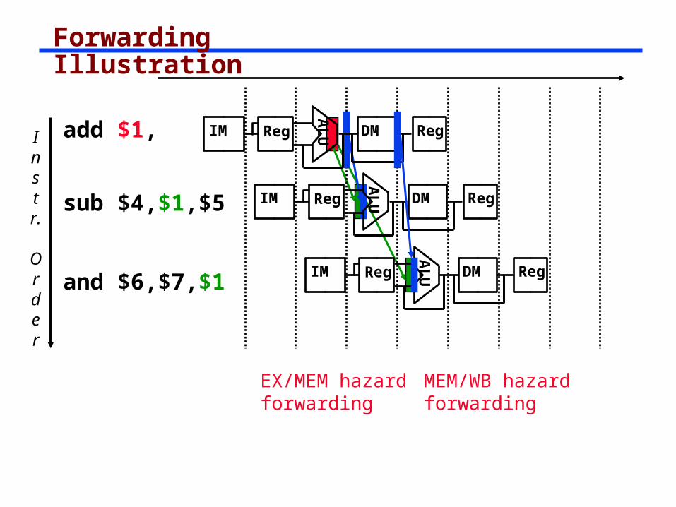
Forwarding Illustration
Instr.
Order
add $1,
sub $4,$1,$5
and $6,$7,$1
AL
UIM Reg DM Reg
AL
UIM Reg DM Reg
AL
UIM Reg DM Reg
EX/MEM hazard forwarding
MEM/WB hazard forwarding
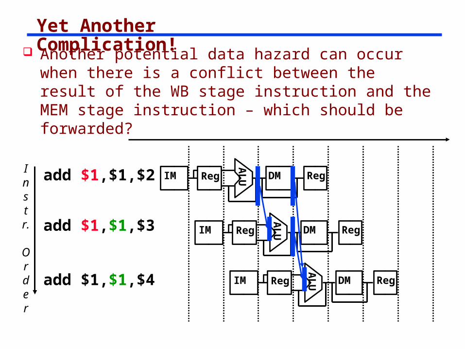
Yet Another Complication!
Instr.
Order
add $1,$1,$2
AL
UIM Reg DM Reg
add $1,$1,$3
add $1,$1,$4
AL
UIM Reg DM Reg
AL
UIM Reg DM Reg
Another potential data hazard can occur when there is a conflict between the result of the WB stage instruction and the MEM stage instruction – which should be forwarded?
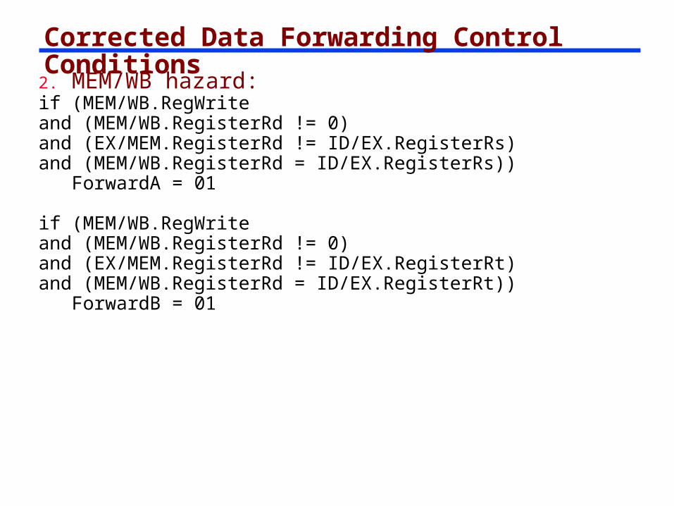
Corrected Data Forwarding Control Conditions
2. MEM/WB hazard:if (MEM/WB.RegWriteand (MEM/WB.RegisterRd != 0)and (EX/MEM.RegisterRd != ID/EX.RegisterRs)and (MEM/WB.RegisterRd = ID/EX.RegisterRs))
ForwardA = 01
if (MEM/WB.RegWriteand (MEM/WB.RegisterRd != 0)and (EX/MEM.RegisterRd != ID/EX.RegisterRt)and (MEM/WB.RegisterRd = ID/EX.RegisterRt))
ForwardB = 01
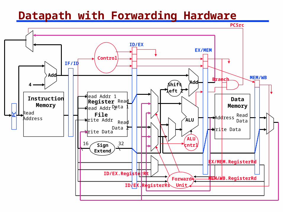
Datapath with Forwarding HardwarePCSrc
ReadAddress
InstructionMemory
Add
PC
4
Write Data
Read Addr 1
Read Addr 2
Write Addr
Register
File
Read Data 1
Read Data 2
16 32
ALU
Shiftleft 2
Add
DataMemory
Address
Write Data
ReadData
IF/ID
SignExtend
ID/EXEX/MEM
MEM/WB
Control
ALUcntrl
Branch
ForwardUnit
ID/EX.RegisterRt
ID/EX.RegisterRs
EX/MEM.RegisterRd
MEM/WB.RegisterRd
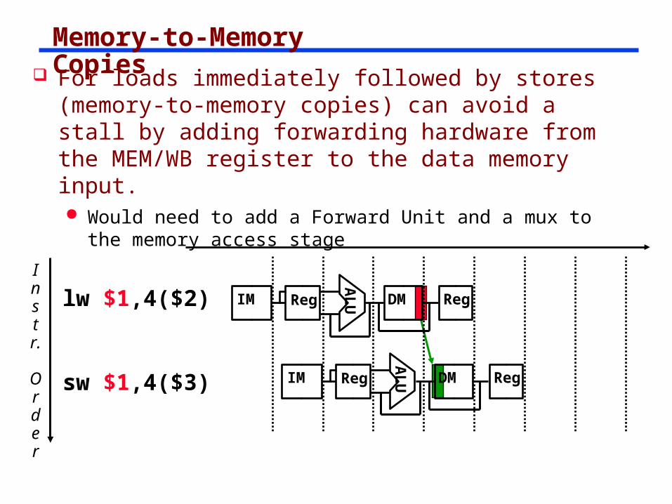
Memory-to-Memory Copies
Instr.
Order
lw $1,4($2)A
LUIM Reg DM Reg
sw $1,4($3)
AL
UIM Reg DM Reg
For loads immediately followed by stores (memory-to-memory copies) can avoid a stall by adding forwarding hardware from the MEM/WB register to the data memory input. Would need to add a Forward Unit and a mux to the
memory access stage
stall
Forwarding with Load-use Data Hazards
Instr.
Order
lw $1,4($2)
sub $4,$1,$5
and $6,$1,$7
xor $4,$1,$5
or $8,$1,$9A
LUIM Reg DM Reg
AL
UIM Reg DM
AL
UIM Reg DM RegA
LUIM Reg DM Reg
AL
UIM Reg DM Reg
AL
UIM Reg DM Regsub $4,$1,$5
and $6,$1,$7
xor $4,$1,$5
or $8,$1,$9
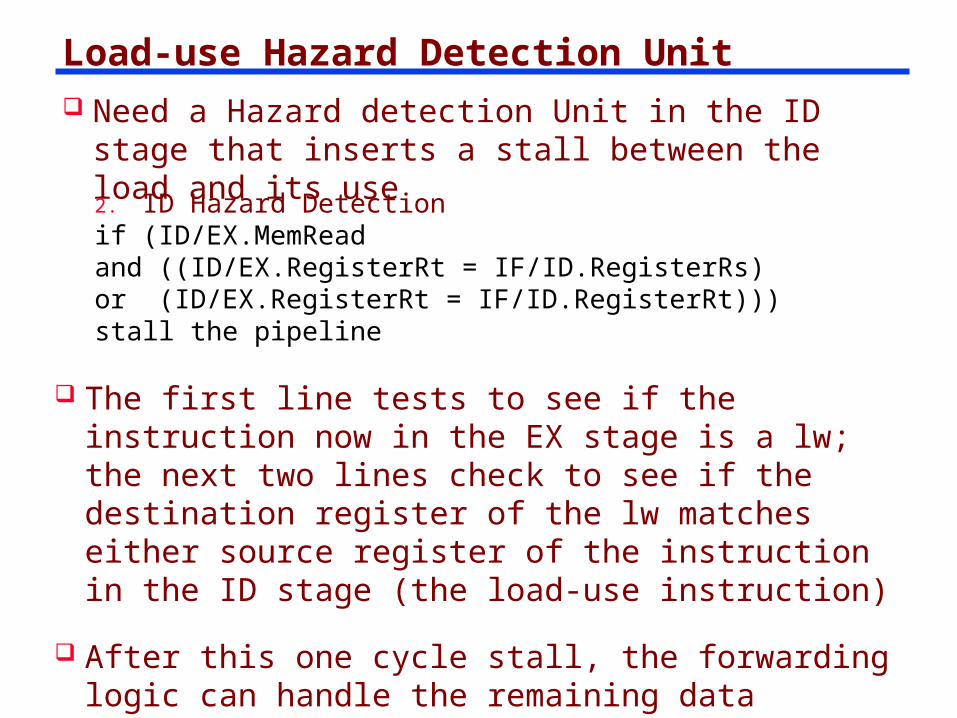
Load-use Hazard Detection Unit Need a Hazard detection Unit in the ID stage that
inserts a stall between the load and its use
2. ID Hazard Detectionif (ID/EX.MemReadand ((ID/EX.RegisterRt = IF/ID.RegisterRs)or (ID/EX.RegisterRt = IF/ID.RegisterRt)))stall the pipeline
The first line tests to see if the instruction now in the EX stage is a lw; the next two lines check to see if the destination register of the lw matches either source register of the instruction in the ID stage (the load-use instruction)
After this one cycle stall, the forwarding logic can handle the remaining data hazards
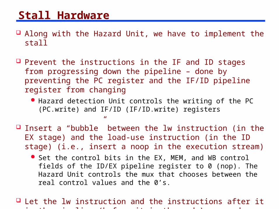
Stall Hardware Along with the Hazard Unit, we have to implement the stall
Prevent the instructions in the IF and ID stages from progressing down the pipeline – done by preventing the PC register and the IF/ID pipeline register from changing
Hazard detection Unit controls the writing of the PC (PC.write) and IF/ID (IF/ID.write) registers
Insert a “bubble” between the lw instruction (in the EX stage) and the load-use instruction (in the ID stage) (i.e., insert a noop in the execution stream)
Set the control bits in the EX, MEM, and WB control fields of the ID/EX pipeline register to 0 (nop). The Hazard Unit controls the mux that chooses between the real control values and the 0’s.
Let the lw instruction and the instructions after it in the pipeline (before it in the code) proceed normally down the pipeline
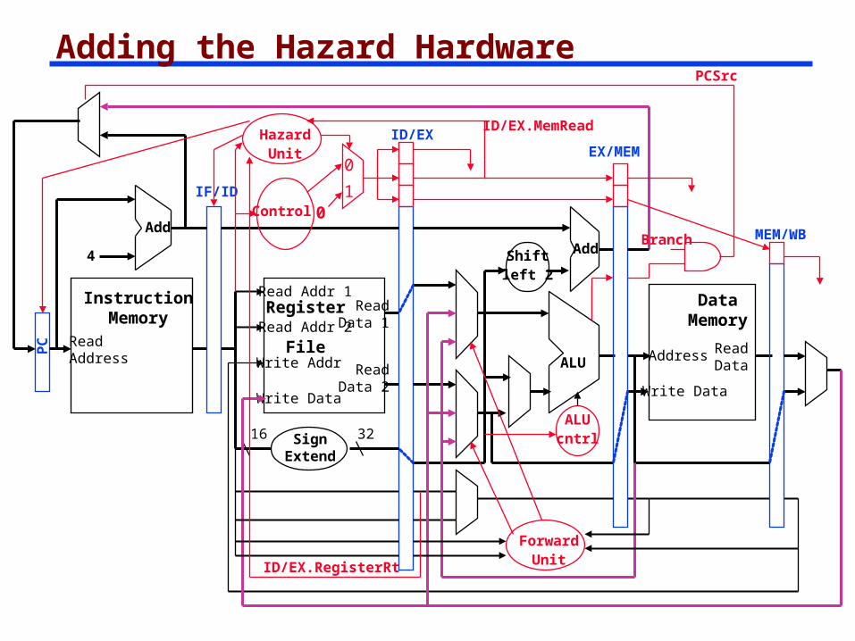
Adding the Hazard Hardware
ReadAddress
InstructionMemory
Add
PC
4
Write Data
Read Addr 1
Read Addr 2
Write Addr
Register
File
Read Data 1
Read Data 2
16 32
ALU
Shiftleft 2
Add
DataMemory
Address
Write Data
ReadData
IF/ID
SignExtend
ID/EXEX/MEM
MEM/WB
Control
ALUcntrl
Branch
PCSrc
ForwardUnit
HazardUnit
0
1
ID/EX.RegisterRt
0
ID/EX.MemRead