Embed Size (px)
Citation preview

Edition 2010
Tel. +43 (0)2252 600-0Fax +43 (0)2252 600-100Web: www.klinger.kfc.at
KLINGER Ballostar KHA3 pieces ball valveDN 10 – 150

2
2
3
1
A
B
C
The sealing element from Klingeroffers safety for many years.
The sleeveConsists of a soft material with good flow
characteristics (PTFE) so that the sealingelement is reliably held in position. A graphitering provides an effective sealing and protectionagainst high termal loads in the Fire Safe version.
The diaphragm springThanks to the spring load a tight fit of the
sealing ring to the ball is guaranteed independentof fluid pressure and direction.
The sealing ringThe ring is enclosed on three sides by
metal.Therefore it is able to absorb the incorporat-ed spring load and transfers the force of the ballwithout suffering any deformation.
Standard:
KFC-25
For applicationsup to 300°C,sealing ring madeof .
Resistant tochemicals:
PTFE
For an extreme highleak tightness andspecial application in thechemical industry, sealingring made of .
Resistant to wear:
with metal insert
For abrasive fluids andthose containing solids.Sealing ring made of
.
Temperatureresistant:
metalinsert and additionalgraphite ring
For high temperaturerange up to 400°C.Sealing ring with
.
Vacuum appli-cation:
Viton
Reliably leak-proofat low pressure andfine vacuum.sealing ring.
Fire Safe:
Special sleeve
Safety acc. to API 607and EN ISO 10497.
andsealing ring made ofKFC-25.
The sealing element is the heart of a valve. If a valve can reliably fulfill the shut off or controlling functions is determined by the seal.Who or whatever controls the sealing element, controls safety.
Klinger is the only manufacturer in the world who offers both - valves and gaskets. It is obvious that over a hundred years of ex-perience in sealing technology has led to a natural advantage in competition. You are just about to see a part of it.
Here we show you the main differences of the Klinger sealing element. On the next pages we explain how these advantages take effecton the entire valve concept.
One principle, six safeties! Each sealing element can be replaced by another. This allows quick and easy adjust-ment of the valve to altering requirements and service conditions:
The sealing systemdecides a ball valve’s quality

3
1
55
4
5
22
2
3
3
4
1
Only Klinger offers a ball valvewith an “automatic sealing chamber”
On the previous two pages we informed youabout the special features of the sealing element.On this page we want to explain how the “incorporatedspring load” affects the function of the valve. In thethe process an “automatic sealing chamber” is formedwhich is unique in the world of valve engineering
In conventional ball valves, the mediumonly acts on the ball in the flow direction.
In a KLINGER Ballostar KHA ball valve,the complete sealing element is charged
with the medium pressure. .Advantage:
With an increasing differential pressurethe additional forces increase as well.
This relieves the preloaded diaphragmspring and increases the service life.
®
The automatic sealingchamber: Absolutelyleaktight, even at lowmedium pressure or
vacuum.
This scetch shows how much larger thepressure absorbing surface of a Klingersealing element is.
When connecting the flanges with the centrepiece the forces of the preloaded springs arereleased and press the sealing rings to the ball.
This happens irrespective ofwhether there is medium pressureor not! The forces still actat very low differentialpressures and vacuum.
Medium pressure absorption areain competitive systems:
Ball area only.
Medium pressure absorption area at Klinger:Ball and diaphragm spring area.
The accumulated force of the sealing elementsacts in both directions!
Since the “automatic sealing chamber“ actsbidirectional, the KLINGER Ballostar KHA isideal for installations with changing flow directions.
®
3

At option: The bracket for mounting theactuator, where direct mounting is eitherrecommended or requested.
- The elastic sealing element for theport. Six different materials and versions:KFC-25, PTFE, metal, metal in high-tem-perature version, Viton, Fire Safe.
- Connections designed as flange,threaded connections or weld ends eitherfull or reduced bore.
The lever is included in the standardscope of supply.
- The operating bolt extension forfluids in the low temperature range, alsowith insulation, depending on the job.
- Reloadable stuffing boxes for theoperating stem. Three different versionsand materials : Graphite (retightenable),Viton O-rings (**not retightenable) andlabyrinth (retightenable).
E
4 52 3
1
6
7
D
B
The ball of acid-resistant stainlesssteel.The valve body, two different
materials to choose from.The ISO top flange is the definedconnection to the actuator.
Different sealing elements in the boreof different material combinations
Connecting bolts and nuts ofdifferent materials to choose from,suitable for temperature ranges from+400°C to -196°C.
Electro-mechanic or pneumaticactuators, directly or with mountingparts attached to the ISO top flange.
A
C
D
E
1
2 3
4
7
9 13
14 20
6
B
8
C
A
4
* New type of hand lever (singlepiece, fine casted) made of steel
** The stuffing box with VitonO-rings can not be retightened
**
*

14 16 18
15 17 19
20
10 11 12 139
5
You can fit, retrofit or convert yourball valve for every special operatingcondition or application by choosingand combining the various versions ofthe system components.
Thanks to the modular system,the safety of the ball valve is quite cost-efficient, because you only buy what youreally need and don’t waste money on”panic surcharges“ or unnecessaryadditional product features.
The fields of application for bodymaterials, sealing elements, andconnecting bolts at different pressuresand temperatures are shown in the safetydiagrams on the pages 8-9.
We attach great importance to the factthat the low torques of our ball valvesdefinitely result in the choice of a cheaperactuator with lower torque output. For moreinformation on the proper torque please seepages 14-15.
With valves of a modular design,maintenance, repair and retrofitting arecost-efficient and easy. For details seethe following page.

Antistaticball
Discharge flow
Antistaticwasher
*
2. Fire-safe
4. Antistatic design as standard
3. Final pressure tightnessand strength test
5. Locking device for hand lever
6
As an additional sign forhigh application safety and
for our high service standarda final inspection certificate
acc. to EN 10204 - 3.1 isavailable for each orderedKLINGER Ballostar® KHA
ball valve free of charge
The KLINGER Ballostar® KHAfire-safe version acc. toAPI Standard 607 (4.th Ed.) andEN ISO 10497 is equipped withspecial sealing elements (FS).
Additional features ensure thatKLINGER Ballostar® KHA are best suitablefor different customer needs and fields ofapplication:
* beginning withsize DN 50
As standard, the KLINGER Ballostar® KHAis equipped with an antistatic equipment
acc. to ISO 7121 or EN 1983.
It goes without saying, that a lever interlockingdevice is a standard feature. A single pin is enough to
connect lever and body. The easy way to ensure adequateprotection against unintentional use.
1. CE markingKLINGER Fluid Control fulfills the requirementsof the Pressure Equipment DirectivePED/97/23/EC. Therefore our completerange of valves (beginning with sizeDN 32) is marked with the CE-sign.

7
10
10
10
100 10 20 30 40 50 60 70 80 90 100
Actuations x 1,000
-4
-5
-6
-3
Leak rate after100.000 actuations7,5 .10 mbar-4 l/s(= 0.00075 mbarl/s)
Leak rate after50.000 actuations9 .10 mbar-5 l/s(= 0.00009 mbarl/s)
max. permissibleleak rate acc. to TA-Luft3 .10 mbar-3 l/s(= 0.003 mbar l/s)
max. permissible leakrate acc. to VDI 2440
THE SAFETY MARGINOF KLINGER
5. ActuatorsSafety with guaranteeSummary of the current typeapprovals
Valve according to TA-Luft(=technical instruction on airpollution control) and VDI 2440The requirements for limitingemissions to prevent air pollution(TA-Luft) are clearly fulfilled.The determination of the leakage rateacc. to VDI 2440 (emission control refin-eries) was successfully accomplished.Fire safetyThe fire-safe test performed acc. toAPI Standard 607 and EN ISO 10497.Valve for liquid fuelThe ball valve is approved as a safetycontrol system for furnaces using liquidfuels, under European Standard EN 264.Valve for gaseous fuelThe ball valve is approved as a safetycontrol system for furnaces usinggaseous fuels, under EuropeanStandard EN 161.Valve for gases and hazardousliquidsThe valve passed the type test with evi-dence acc. to VdTÜV 1065.This also covers the requirements ofVbF, Gas-HL-VO, TRB 801 No.45,DIN 3840, DIN 3230 Part 3,DIN 3230 Part 5/PG3 and Part 6,certified by VdTÜV Essen.Valve for tanks transportinghazardous goodsThe type test for valves used in tankstransporting hazardous goods isapproved and also covers therequirements of GGVSE/ADR/RID,TRT 002, TRT 006, TRT 042,TRG 770 Annex 2,DIN 3230 Part 6, AD 2000 leaflet A4.Valve for use with oxygenApproval for use with oxygen wasissued by the Federal Institute forMaterial Research and Testing(BAM) Berlin.Valve as gas house connectionApproval acc. to ÖVGW (also validfor DVGW and SVGW)
6. Standard leak tightness: 10 -4
Klinger is the only concern inthe world who produces both valves andseals. The synergistic effectof these two fields of know-ledge can be seen in theseals for the bore and thestuffing box. The diagramshows the safety marginof the ball valve comp-ared to the requirementsof VDI 2440 and theTechnical Guidlines Air(TA-Luft).
The labyrinthstuffing box
The top flange acc. to ISO 5211 isconnected to the actuator either directlyor via a bracket and coupling.
You can fit and dismantle therequired actuator type any time, evenwhen the plant is in operation, whichmakes changing of an actuator after abreakdown very easy.
Tested with the ball valveKHA-G 1" with Helium
Leak
rate
mba
rl/s

8
6
37,3
60
48
75
3028,225
1816
10
45
100
63
40
PTFEKFC-25/ Metal/ Fire Safe
Metal
Viton
–10
–60
–80
217
200
156,
5
120
10550
–25
–45
400
300
150
Body
Cap screws Fkl. A4-70 until -60° CScrews 8.8 - A2L
Screw bolts A4-70 until -85° C
Graphite max. PN 40
Viton max. PN 40
PTFE labyrinth
Bolts, screws andcap screws
Temp. °C
Sealing elements
Stuffing box
PN pressure (bar)(1bar = 0.1MPa)
2
Maximum for PTFE
Maximum for KFC-25
Maximum for Viton
Max
imum
forM
etal
/Spe
cial
PN10
0
366
Max
imum
for M
etal
/Spe
cial
PN63
Max
imum
for M
etal
/Spe
cial
PN40
PN pressure (bar)(1bar = 0.1MPa)
Screws 8.8 - A2L
PTFEKFC-25
16
69,913,4
-10
120
180
200
289,
530
0
150
Metal
Viton
PTFE compact/ PTFE labyrinth
Viton
With an operating pressurebetween 75 and 100% of the nominalpressure, the field of application in allthree pressure stages (PN 100, 63, 40)is down to -10°C.
If the operating pressure incl.load peaks is between 25 and 75 %,the field of application is extended to-60°C assuming cap screws of A4-70.
If the operating pressure reach-es max. 25% of the nominal pressure,the safety range for the valve is extend-ed to -85°C assuming screw bolts ofA4-70.
A decrease in the operating pres-sure in the nominal pressure rangeincreases in the field of applicationin the temperature range.

9
PN pressure (bar)(1bar = 0.1MPa)
Maximum for PTFE
Cap screws Fkl. A4-70 until -60° CScrew bolts A4-70 until -196° C
PTFEKFC-25, Metal, Fire Safe
63
40
47,2
6
24,428,4
57,3
–10
–25
–45 20
200
208
158
150
130
251
300
–196
Tem
p.°C
–60
–85
Graphite max. PN 40
Viton max. PN 40
PTFE labyrinth
Viton
Metal
1)
2)
2) resistant to inter-crystalline corrosion
400
36,4
Maximum for KFC25
Maximum for Metal/Special
Bolts,screws andcap screws
Temp. °C
Sealingelements
Stuffing box
The influences of the three bodymaterials, the sealing materials and thescrews on the range of application ofthe ball valve are clearly shown in thept diagrams.
This is safety à la carte. Plot youroperating point in the diagram fields tofind out whether the safety marginsmeet your requirements or not. At thesame time you can see which para-meters have to be changed.
Choosing your ball valve in thisway means optimizing the economy ofthe valve.
1) For plants that are subjected toan acceptance test, to pleasecontact Klinger.

Fluids
Conditionsof use
Approvalsand certificates
Water/hot water
Mineral oil
Heat transfer oil
Liquid gas/low temperature
Saturated steam
Misc. gases
Vacuum/ high vacuum
Hot steam
0xygen
Standard application
High no. of cycles
Frequent temp. changes
Fire safety (Fire Safe)
Chemical industry
Abrasive fluids
Temperature range [°C]
VDI 2440
ÖVGW
Fire Safe API 607
TA-Luft
VdTÜV 1065
EN 161
EN 264
The standard ball valves are equippedwith the stuffing box ”PTFE labyrinth“and the sealing element ”KFC-25”.Ball valves which differ from standardare identifiable by an attached type plate.
PTFE labyrinth
-196/+300
Graphite compact
-85/+400
Viton
-25/+150
10
PTL GRK VIT

recommended
* Permissible, internal leakage rate at 6 bar water pressure:1 permille of the -value per minutekv
** Special equipment and accessory for cryogenic service.Fore more information please contact our sales team!
less suitable not recommended
KFC-25
-60/+300
PTFE
-196**/+200
Metal*
-60/+300
Metal/Special*
-60/+400
Viton
-25/ +150
Fire Safe
-60/+300
11
KFC PTF MET MES VIR FIS

12
Spare part kit «sealing elements»Two pieces of preloadedsealing elements inoriginal KLINGER quality.
Spare part kit «set of seals»Stuffing box components and
sealing elements in originalKLINGER quality
Both guarantee promises andwarranty are based on threebehaviour patterns:
1. You use onlyoriginal Klinger parts,which can be recognizedby the „ Q” sign.
2. Maintenance andassembly work has always to be doneaccording to the guidlines ofKLINGER Fluid Control.
3. Acceptance tests are performedexklusively by organisations authorizedby KLINGER Fluid Control
Maintenance and service without dismantling from line
Only the nuts of three of the four screw bolts need to be slightly loosenedfor maintenance and service work. The fourth nut is removed and the boltretracted. The middle piece of the valve can then be easily swung out, asshown in the schematic scetch below.
The two sealing elements in thebore are then accessible andcan be easily removed andreplaced by new ones.
And changing thestuffing box seals,removing the ballor the operating stemis just as easy.
For a better understandingof the spare part kits:The sum of all parts in the spareparts kits are always forminga functional unit.Depending on the nominal sizeof the valve or the applicationparameters the number of partsand/or their materials may varyparts and/or their mate-with an identical function. On thisnote, the kit illustrations onlyserve for a better understandingand, in most cases only have asymbolic meaning.
Spare part kit «ball»The ball, standard versionin original KLINGER quality
If you are the sort of person whoasks: what does the valve cost after it hasbeen purchased, and if you relate theinvestment to follow-up costs, then wehave some good news for you.
In the fields of application ofball valves, with the KLINGER Ballostar ®
KHA now you can achieve a whole newdimension in safety and economy forplant maintenance with a low capital tie-up and fewer working hours.
Not only does the modular techno-logy of the components offer the bigadvantages of exactly matched originalequipment, but it also ensures spot-onsubstitution in maintenance and upgrad-ing.
You only have to replace what needs tobe replaced. This considerably increasesthe service life of the valves in the sys-tem, and at the same time cuts the costsof plant maintenance for stock keepingand assembly.
What is not lowered is the safetystandard, which in many cases can in facteasily be improved, if required.
The quality sign on the spare partspackages is your guarantee of originalKLINGER quality.

13
Pressure drops
Size of the ball valve
The coefficients quoted in the tablecan be used to calculate the rightsize or pressure drop of theKLINGER Ballostar® KHA ball valves.Both the and kvS values are shown.
kvs values valid for water with a densityof 1000 kg/m3.
= or =kv 1000w 2 10 -5
2
Flow ratePressure dropDensityVelocity
so that:in m 3/hin barin kg/m 3
in m/s
or
When choosing a valve note that thekv -value should be bigger and the
-value smaller than the calculatedvalue.
=w 2
2 10 5
kv =1000
2
DN (mm) kvs0.350.230.200.140.120.110.10
0.0760.0670.0580.051
0.960.540.410.350.330.320.310.300.300.30
6.818.835.866.8118193316607980
1645274216.3
3463,9108174299460730
11411642
101520253240506580
100125
20R1525R2032R2540R3250R4065R5080R65
100R80125R100150R125
Flow characteristic values(m3/h)
Q
Q

1/2"3/4"1"
1 1/4"1 1/2"
2"2 1/2"
3"4"5"
1520253240506580
100125
5.4
10.8
12.6
15.3
21.3
30.3
51.0
72.0
120.0
202.5
5.6
11.1
13.5
16.6
23.6
33.3
56.3
85.5
137.8
238.1
5.8
11.4
14.5
17.9
26.0
36.3
61.6
99.0
155.6
273.8
6.0
11.8
15.6
19.4
28.8
39.9
68.0
115.2
177.0
316.5
6.1
12.1
16.3
20.4
30.7
42.2
72.3
126.0
191.3
345.0
6.3
12.4
17.2
21.7
33.1
45.2
77.6
139.5
209.1
380.6
6.5
12.7
18.2
23.0
35.4
48.2
82.9
153.0
226.9
416.3
6.4
13.3
20.0
25.6
40.1
54.1
93.5
180.0
262.5
487.5
7.2
14.0
21.9
28.2
44.9
7.7
14.8
24.3
31.5
51.0
9.0
17.1
2 PTFE
Min. torques for the various seals
1/2"3/4"1"
1 1/4"1 1/2"
2"2 1/2"
3"4"5"
1520253240506580
100125
7.5
15
18
25
40
55
85
140
250
450
7.8
15.7
19.4
26.7
44.8
64.4
101.9
172.5
293.8
580
8.2
16.4
20.9
28.3
49.5
73.8
118.8
205
337.5
710
8.5
17.2
22.6
30.3
55.2
85
139
244
390
866
8.8
17.8
23.7
31.7
59
92.5
152.5
270
425
970
9.1
18.5
25.1
33.3
63.8
101.9
169.4
302.5
468.8
1.100
9.5
19.2
26.6
35.0
68.6
111.3
186.3
335
512.5
10.1
20.6
29.4
38.3
78.1
130
220
400
600
10.8
22
32.3
41.7
87.6
11.6
23.8
36
46
100
14
29
3 Metall/ metal
Transfer the design torque and the control pressure to obtainthe working point A. Now you choose the actuator with the nexthigher torque. In this case it is RC 230-DA.
Remote Control,double-acting actuator
10
60
80
100
200
400
600
20
30
40
Torq
ue[N
m]
3,5 4 4,5 5 6
51
5,5
A
1520253240506580
100125
6.2
12.4
15
18.4
27.8
40.6
66.3
114
183.8
317.5
5
6.4
12.7
16.1
19.9
30.6
44.3
72.5
132
207.5
365
10 16
6.8
13.4
18.1
22.7
36.1
51.5
85
168
255
460
20
7
13.8
19.2
24.1
38.9
55.1
91.3
186
278.8
507,5
25
7.2
14.1
20.2
25.6
41.7
58.8
97.5
204
302.5
555
30
7.6
14.8
22.3
28.4
47.2
66
110
240
350
650
40Differential pressure (bar)
inch mm
Nominaldiameter
DNTorque Nm
8
15.5
24.3
31.3
52.8
50
8.5
16.4
27
35
60
63
10
19
100
KFC-251
1/2"3/4"1"
1 1/4"1 1/2"
2"2 1/2"
3"4"5"
6
12
14
17
25
37
60
96
160
270
0
6.6
13.1
17.3
21.6
33.948.6
80
153.6
236
422
1520253240506580
100125
15.9
20.2
29.7
49.4
72.2
150.0
219.4
5
17.8
22.4
34.4
58.8
89.4
200.0
278.8
10 16Differential pressure (bar)
inch mm
Nominaldiameter
DNTorque Nm
Viton4
1/2"3/4"1"
1 1/4"1 1/2"
2"2 1/2"
3"4"5"
14.0
18.0
25.0
40.0
55.0
100.0
160.0
0
20.0
25.0
40.0
70.0
110.0
260.0
350.0
14
KLINGER recommends to use a factor of 1.5, i.e.plus 50% for standard calculations.
Information re-garding othersizes or differ-ential pressureson request

15
Klinger recommends touse a faktor of 1.5, i.e.plus 50% for standardcalculations
RC 230-DA*The optimal actuator
Nominal width DN 40Sealing element KFC 25
Differential pressure 15 barControl pressure 5.5 bar
Starting data
Result from table 1
Min.torque 33,9 Nm
Multiply by safetyfactor 1.5
(33,9 x 1.5 = 50,85)
Designtorque 50,85 Nm
Double-acting actuator
Enter design torque(51 Nm)
and control pressure(5.5 bar)
in diagram
Single-acting actuator
Design torque andcontrol pressure
(diagram not shown)
Function of theactuator
Cont rol pressure P St[bar ]
RC 260-DA
RC 250-DA
RC 240-DA
RC 230-DA
RC 220-DA
RC 210-DA
Both pneumatic and electro mechanicoperated actuators can be used for theautomation of a KLINGER Ballostar KHAball valve.
The torque of the actuator isdetermined by the requireddifferential pressure, not by thenominal pressure.
Please note, that a KLINGERBallostar® KHA ball valve has the same,relatively low torque in all operatingstates.
When both aspects are considered,the actuator can often be smaller by oneor two sizes. A smaller actuator meanssmaller body measurements and needsless space for installation.This is important for plant constructionwhere a few milimetres often make a bigdifference. An actuator with lower power isof course more energy-saving. And this dayby day for many years!
Flowchart and examplefor pneumatic actuators(in this case producedby Remote Control)
* Of course all makes of other actuator manufacturers can be attached without anydifficulty to automate Klinger Ballostar®ball valves!
By simply choosing the appropriatetorque for your operation conditionsyou will reduce both investment andfollow-up costs.

Type KHA-FLMarerial code III/
Grey cast ironPN 16
Pressure and temperature limits
ConnectionsFlanges acc. to EN 1092-2(former DIN 2533)DimensionsFace-to-face dimensions acc. toEN 558-1, basic series 1, or DIN 3202-F1.Main useGenerally for liquids and gases, otherfluids see resistance table.
Leak tightnessSeat leak tightness: EN 12266-1 P12,leakage rate A (formerly DIN 3230 part 3BO) stem leak tightness acc. toEN 12266-1 P11 and BQ strength:EN 12266-1 P10 and BQAutomationFlange connection acc. to ISO 5211,allows direct mounting of the actuator ormounting with bracket.Pneumatic and electro-mechanicactuators suitable.
rotated in the section
H
h1D
g
k0,2
b
G
f
l
h4h5
* lz
1/2 L
d
SW1
rotated in thesection
A
d3
d4
d2
SW1
1/2 L
L
Material IIIGrey cast iron
Steel Nickel plated1.41041.44041.44011.43101.4404K-Flon
KFC-25Xc/KFC-25SINT D10
1.4401EN-GJL-250
8,8-A2L8-A2L
1.0619
LeverOperating stemStuffing box nutLoading ringBelleville washerFemale support ringStuffing box*Slip ringSealing element*Supporting ringBallFlanged end pieceScrew boltHexagon nutBody
16
DN
15506580100
L130230290310350
G130315315500500
PN
1616161616
h13590
100122135
Ød15506580
100
ØD95
165185200220
Øg45102122138158
f23333
b1420202224
Øk65
125145160180
l1418181818
lz*44488
h57
15152020
h434444
Ød45,810101212
Ød23055557070
SW1
817172222
Ød3427070
102102
A427070
102102
ISOF04F07F07F10F10
Weightkg
2.413.316.430.136.8
H80
131141162176
Dimensions Connecting dimensions Mounting flange for actuator
*lz: number of drilling holesmmnisnoisnemidlla
Design features3-piece ball valve,floating ball, antistatic, lockable.Double leak tightness bi-directional.Modular construction kit system:several versions of stuffing boxesand sealing elements available
In the interest of technical progress designs and dimensions are subject to modification.
* Standard version
see pages 8-9

H
h1D
g
k0,2
b
G
f
l
h4h5
* lz
1/2 L 1/2 L
L
rotated in the section
SW1
d
rotated in thesection
d2
A
d3
d4
Material VIIICarbon steel
Material XcAcid-res.
stainless steel
1.41041.44041.44011.43101.4401K-Flon
KFC-25Xc/KFC
SINT D101.44011.0619
8,8-A2L8-A2L
1.0619
Steel Nickel plated1.44041.44041.44011.43101.4401K-Flon
KFC-25Xc/KFC1.44041.44011.4408A4-70
A41.4408
LeverOperating stemStuffing box nutLoading ringBelleville washerFemale support ringStuffing box*Slip ringSealing element*Supporting ringBallFlanged end pieceScrew boltHexagon nutBody
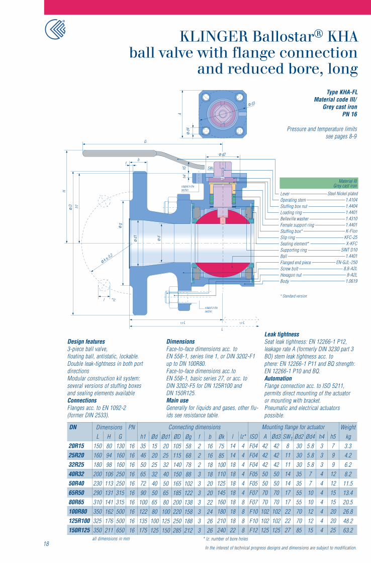
Type KHA-FLMaterial code VIII/ Steel
and Material code Xc/Acid-resistant steel
PN 40
Pressure and temperature limits
Design features3-piece ball valve,floating ball, antistatic, lockable.Double leak-tightness in both portdirections.Modular construction kit system:several versions of stuffing boxesand sealing elements available.
ConnectionsFlanges acc. to EN 1092-1 (DIN 2535).DimensionsFace-to-face dimensions acc. toEN 558-1, basic series 1, or DIN 3202-F1.Main useGenerally for liquids and gases, otherfluids see resistance table.
Leak tightnessSeat leak tightness: EN 12266-1 P12,leakage rate A (formerly DIN 3230 part 3BO) stem leak tightness acc. toEN 12266-1 P11 and BQ strength:EN 12266-1 P10 and BQ
Fire safe acc. to API 607 and EN ISO 10497.AutomationFlange connection acc. to ISO 5211,permits direct mounting of the actuator ormounting with bracket. Pneumatic andelectrical actuators possible.
DN
101520253240506580100125
L120130150160180200230290310350400
G130130160160250250315315500500650
PN
4040404040404040404040
h135354650657290
100122135175
Ød101520253240506580
100125
ØD9095
105115140150165185200235270
Øg404558687888
102122138162188
f22222333333
b1616181818182022242426
Øk60657585100110125145160190220
l1414141418181818182226
lz*44444448888
h57799
12121515202025
h433334444444
Ød45.85.85.85.8771010121215
Ød23030303035355555707085
SW1
88
111114141717222227
Ød34242424250507070
102102125
A4242424250507070
102102125
ISOF04F04F04F04F05F05F07F07F10F10F12
Weightkg2.32.83.85.17.99.8
14.118.330.939.752.2
H80809498
106113131141162176211
Dimensions Connecting dimensions Mounting flange for actuator
17*lz: number of drilling holesmmnisnoisnemidlla
In the interest of technical progress designs and dimensions are subject to modification.
* Standard version
see pages 8-9
Fire safety (special version).
Material IIIGrey cast ironrotated in the
section
h4
H
h1D
d1 d
g
k0,2
bd2
G
f
l *lz
SWh5 1
1/2 L 1/2 L
L
rotated in thesection
A
d3
d4
1.41041.44041.44011.43101.4401K-Flon
KFC-25X-KFC
SINT D101.4401
EN-GJL-2508,8-A2L
8-A2L1.0619
LeverOperating stemStuffing box nutLoading ringBelleville washerFemale support ringStuffing box*Slip ringSealing element*Supporting ringBallFlanged end pieceScrew boltHexagon nutBody
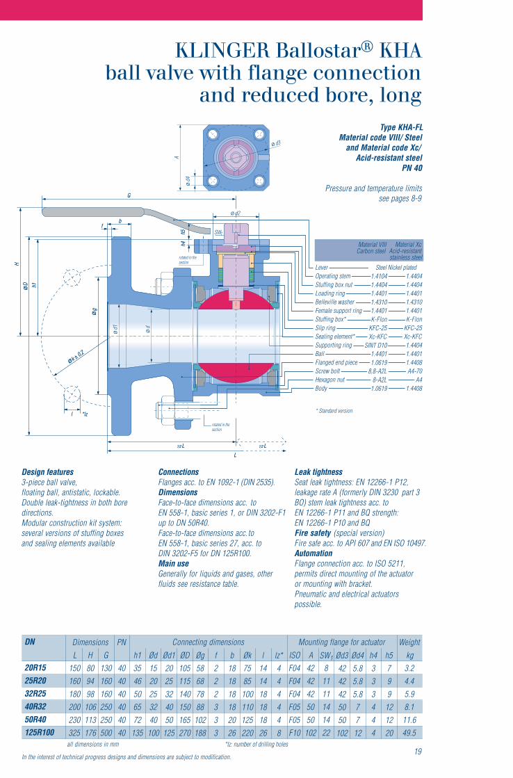
Type KHA-FLMaterial code III/
Grey cast ironPN 16
Pressure and temperature limits
Design features3-piece ball valve,floating ball, antistatic, lockable.Double leak-tightness in both portdirectionsModular construction kit system:several versions of stuffing boxesand sealing elements availableConnectionsFlanges acc. to EN 1092-2(former DIN 2533).
DimensionsFace-to-face dimensions acc. toEN 558-1, series line 1, or DIN 3202-F1up to DN 100R80.Face-to-face dimensions acc. toEN 558-1, basic series 27, or acc. toDIN 3202-F5 for DN 125R100 andDN 150R125.Main useGenerally for liquids and gases, other flu-ids see resistance table.
18
DN
20R1525R2032R2540R3250R4065R5080R65100R80125R100150R125
L150160180200230290310350325350
G130160160250250315315500500650
PN
16161616161616161616
h1354650657290
100122135175
Ød1520253240506580
100125
ØD105115140150165185200220250285
Ød120253240506580
100125150
Øg58687888
102122138158188212
f2223333333
b16161818202022242626
Øk7585100110125145160180210240
l14141818181818181822
lz*4444448888
Weightkg3.34.26.28.2
11.513.420.526.848.263.2
H809498
106113131141162176211
Dimensions Connecting dimensions
* lz: number of bore holesall dimensions in mm
h5799
12121515202025
h43334444444
Ød45.85.85.8771010121215
Ød230303035355555707085
SW1
8111114141717222227
Ød342424250507070
102102125
A42424250507070
102102125
ISOF04F04F04F05F05F07F07F10F10F12
Mounting flange for actuator
Leak tightnessSeat leak tightness: EN 12266-1 P12,leakage rate A (formerly DIN 3230 part 3BO) stem leak tightness acc. tophere: EN 12266-1 P11 and BQ strength:EN 12266-1 P10 and BQ.AutomationFlange connection acc. to ISO 5211,permits direct mounting of the actuatoror mounting with bracket.Pneumatic and electrical actuatorspossible.
In the interest of technical progress designs and dimensions are subject to modification.
* Standard version
Steel Nickel plated
see pages 8-9
Type KHA-FLMaterial code VIII/ Steel
and Material code Xc/Acid-resistant steel
PN 40
Pressure and temperature limitsh4
H
h1ØD
Ød1 Ød
Øg
Øk �0,2
bd2
G
f
l *lz
SWh5 1
1/2 L 1/2 L
L
rotated in thesection
1.41041.44041.44011.43101.4401K-Flon
KFC-25X-KFC
SINT D101.44011.0619
8,8-A2L8-A2L
1.0619
1.44041.44041.44011.43101.4401K-Flon
KFC-25X-KFC1.44041.44011.4408A4-70
A41.4408
rotated in thesection
h4
H
h1D
d1 d
g
k0,2
b
G
f
l *lz
h5
1/2 L 1/2 L
L
A
d3
d4
Material VIIICarbon steel
Material XcAcid-resistantstainless steel
1.41041.44041.44011.43101.4401K-Flon
KFC-25Xc-KFC
SINT D101.44011.0619
8,8-A2L8-A2L
1.0619
1.44041.44041.44011.43101.4401K-Flon
KFC-25Xc-KFC1.44041.44011.4408A4-70
A41.4408
LeverOperating stemStuffing box nutLoading ringBelleville washerFemale support ringStuffing box*Slip ringSealing element*Supporting ringBallFlanged end pieceScrew boltHexagon nutBody
Design features3-piece ball valve,floating ball, antistatic, lockable.Double leak-tightness in both boredirections.Modular construction kit system:several versions of stuffing boxesand sealing elements available
ConnectionsFlanges acc. to EN 1092-1 (DIN 2535).DimensionsFace-to-face dimensions acc. toEN 558-1, basic series 1, or DIN 3202-F1up to DN 50R40.Face-to-face dimensions acc. toEN 558-1, basic series 27, acc. toDIN 3202-F5 for DN 125R100.Main useGenerally for liquids and gases, otherfluids see resistance table.
Leak tightnessSeat leak tightness: EN 12266-1 P12,leakage rate A (formerly DIN 3230 part 3BO) stem leak tightness acc. toEN 12266-1 P11 and BQ strength:EN 12266-1 P10 and BQFire safety (special version)Fire safe acc. to API 607 and EN ISO 10497.AutomationFlange connection acc. to ISO 5211,permits direct mounting of the actuatoror mounting with bracket.Pneumatic and electrical actuatorspossible.
DN
20R1525R2032R2540R3250R40125R100
L150160180200230325
G130160160250250500
PN
404040404040
h13546506572
135
Ød1520253240
100
ØD105115140150165270
Ød12025324050
125
Øg58687888
102188
f222333
b181818182026
Øk7585100110125220
l141418181826
lz*444448
h5799
121220
h4333444
Ød45.85.85.87712
Ød34242425050
102
SW1
81111141422
A4242425050
102
ISOF04F04F04F05F05F10
Weightkg3.24.45.98.1
11.649.5
H809498
106113176
Dimensions Connecting dimensions Mounting flange for actuator
19*lz: number of drilling holesmmnisnoisnemidlla
In the interest of technical progress designs and dimensions are subject to modification.
* Standard version
Steel Nickel plated
see pages 8-9
Material IIIGrey cast ironrotated in the
section
h4h5
H
h1D
d1 dg
k0,2
b
d2
G
f
l *lz
SW1
1/2 L 1/2 L
L
rotated in thesection
A
d3
d4
1.41041.44041.44011.43101.4401K-Flon
KFC-25Xc-KFC
SINT D101.44010.6025
8,8-A2L8-A2L
1.0619
M1O
* special drill patternat DN 100R80
85
4588
LeverOperating stemStuffing box nutLoading ringBelleville washerFemale support ringStuffing boxSlip ringSealing elementSupporting ringBallFlanged end pieceScrew boltHexagon nutBody
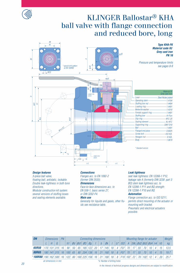
Design features3-piece ball valve,floating ball, antistatic, lockable.Double leak-tightness in both boredirections.Modular construction kit system:several versions of stuffing boxesand sealing elements available.
ConnectionsFlanges acc. to EN 1092-2(former DIN 2533).DimensionsFace-to-face dimensions acc. toEN 558-1, basic series 27,or DIN 3202-F4.Main useGenerally for liquids and gases, other flu-ids see resistance table.
Leak tightnessseat leak tightness: EN 12266-1 P12,leakage rate A (formerly DIN 3230 part 3BO) stem leak tightness acc. toEN 12266-1 P11 and BQ strength:EN 12266-1 P10 and BQAutomationFlange connection acc. to ISO 5211,permits direct mounting of the actuator ormounting with bracket.Pneumatic and electrical actuatorspossible.
20
DN
65R5080R65100R80*
L170180190
G315315500
PN
161616
h190
100122
Ød506580
ØD185204225
Ød16580
100
Øg122138158
f201616
b172121
Øk145160180
l181818
lz*488
h5151520
h4444
Ød4101012
Ød37070
102
Ød2555570
SW1
171722
A7070
102
ISOF07F07F10
Weightkg
13.519.725.7
H131141162
Dimensions Connecting dimensions Mounting flange for actuator
*lz: Number of drilling holesmmnisnoisnemidlla
Type KHA-FKMaterial code III/
Grey cast ironPN 16
Pressure and temperature limits
In the interest of technical progress designs and dimensions are subject to modification.
* Standard version
Steel Nickel plated
see pages 8-9

rotated in thesection
h4h5
H
h1D
d1 dg
k0,2
b
d2
f
l *lz
SW1
1/2 L 1/2 L
L
A
d3
d4
M1O
1) special drill patternfor size DN 100R80
85
4588
rotated in thesection
Material VIIICarbon steel
Material XcAcid-resistantstainless steel
1.41041.44041.44011.43101.4401K-Flon
KFC-25Xc-KFC
SINT D101.44011.0619
8,8-A2L8-A2L
1.0619
1.44041.44041.44011.43101.4401K-Flon
KFC-25Xc-KFC1.44041.44011.4408A4-70
A41.4408
LeverOperating stemStuffing box nutLoading ringBelleville washerFemale support ringStuffing box*Slip ringSealing element*Supporting ringBallFlanged end pieceScrew boltHexagon nutBody
Design features3-piece ball valve,floating ball, antistatic, lockable.Double leak-tightness in both boredirections.Modular construction kit system:several versions of stuffing boxesand sealing elements available.
ConnectionsFlanges acc. to EN 1092-1 (DIN 2535).DimensionsFace-to-face dimensions acc. toEN 558-1, basic series 27,or DIN 3202-F4.Main useGenerally for liquids and gases, other flu-ids see resistance table.Leak tightnessseat leak tightness: EN 12266-1 P12,leakage rate A (formerly DIN 3230 part 3BO) leak tightness trough the atmos-phere: EN 12266-1 P11 and BQ strength:EN 12266-1 P10 and BQ
Fire safety (special version)Fire safe acc. to API 607 and EN ISO 10497.AutomationFlange connection acc. to ISO 5211,permits direct mounting of the actuator ormounting with bracket.Pneumatic and electrical actuatorspossible.
21
DN
65R5080R65
100R801)
L170180190
G315315500
PN
404040
h190
100122
Ød506580
ØD188204235
Ød16580
100
Øg122138162
f151616
b192121
Øk145160190
l181822
lz*888
Weightkg
15.321.329.7
H131141162
Dimensions Connecting dimensions
*lz: number of drilling holesmmnisnoisnemidlla
h5151520
h4444
Ød4101012
Ød37070
102
Ød2555570
SW1
171722
A7070
102
ISOF07F07F10
Mounting flange for actuator
Type KHA-FKMaterial code VIII/ Steel
and Material code Xc/Acid-resistant steel
PN 40
Pressure and temperature limits
In the interest of technical progress designs and dimensions are subject to modification.
** Standard version
Steel Nickel plated
see pages 8-9
rotated in the section
Hh1
ddpD
s
d2
G
h4
SW
30°
1/2 L 1/2 L
L
rotated in thesection
A
d3
d4
Material VIIICarbon steel
Material XcAcid-resistantStainless steel
1.40061.41041.44041.44011.43101.4404K-Flon
KFC-25Xc-KFC
SINT D101.44011.0619
8,8-A2L8-A2L
1.0619
1.40061.44041.44041.44011.43101.4401K-Flon
KFC-25Xc-KFC1.44041.44011.4408A4-70
A41.4408
h5 1
LeverOperating stemStuffing box nutLoading ringBelleville washerFemale support ringStuffing box*Slip ringSealing elementSupporting ring*BallWeld ends, longScrew boltHexagon nutBody
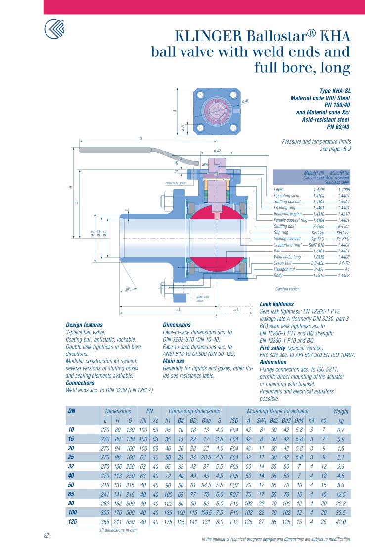
Design features3-piece ball valve,floating ball, antistatic, lockable.Double leak-tightness in both boredirections.Modular construction kit system:several versions of stuffing boxesand sealing elements available.ConnectionsWeld ends acc. to DIN 3239 (EN 12627)
DimensionsFace-to-face dimensions acc. toDIN 3202-S10 (DN 10-40)Face-to-face dimensions acc. toANSI B16.10 Cl.300 (DN 50-125)Main useGenerally for liquids and gases, other flu-ids see resistance table.
Leak tightnessSeat leak tightness: EN 12266-1 P12,leakage rate A (formerly DIN 3230 part 3BO) stem leak tightness acc toEN 12266-1 P11 and BQ strength:EN 12266-1 P10 and BQ.Fire safety (special version)Fire safe acc. to API 607 and EN ISO 10497.AutomationFlange connection acc. to ISO 5211,permits direct mounting of the actuatoror mounting with bracket.Pneumatic and electrical actuatorspossible.
DN
101520253240506580100125
L270270270270270270216241282305356
G130130160160250250315315500500650
VIII1001001006363634040404040
Xc6363634040404040404040
h135354650657290
100122135175
Ød101520253240506580
100125
ISOF04F04F04F04F05F05FO7FO7F10F10F12
Weightkg
0.70.91.52.12.34.88.3
12.522.833.542.0
H80809498
106113131141162176211
Dimensions Connecting dimensionsPN
22all dimensions in mm
h57799
12121515202025
h433334444444
Ød45.85.85.85.8771010121215
Ød34242424250507070
102102125
Ød23030303035355555707085
SW1
88
111114141717222227
A4242424250507070
102102125
S4.03.54.04.55.54.55.56.05.07.58.0
Ødp131722
28,53743
54,57082
106,5131
ØD182228344349617790
115141
Mounting flange for actuator
Type KHA-SLMaterial code VIII/ Steel
PN 100/40and Material code Xc/
Acid-resistant steelPN 63/40
Pressure and temperature limits
In the interest of technical progress designs and dimensions are subject to modification.
* Standard version
see pages 8-9
rotated in the section
Hh1
ddpD
S
d2
G
h4h5 SW1
1/2 L 1/2 L
L
rotated in thesection
30°
A
d3
d4
Material VIIICarbon steel
Material XcAcid-resistantstainless steel
1.41041.44041.44011.43101.4404K-Flon
KFC-25Xc-KFC
SINT D101.44011.0619
8,8-A2L8-A2L
1.0619
1.44041.44041.44011.43101.4401K-Flon
KFC-25Xc-KFC1.44041.44011.4408A4-70
A41.4408
LeverOperating stemStuffing box nutLoading ringBelleville washerFemale support ringStuffing box*Slip ringSealing element*Supporting ringBallWeld ends, shortScrew boltHexagon nutBody
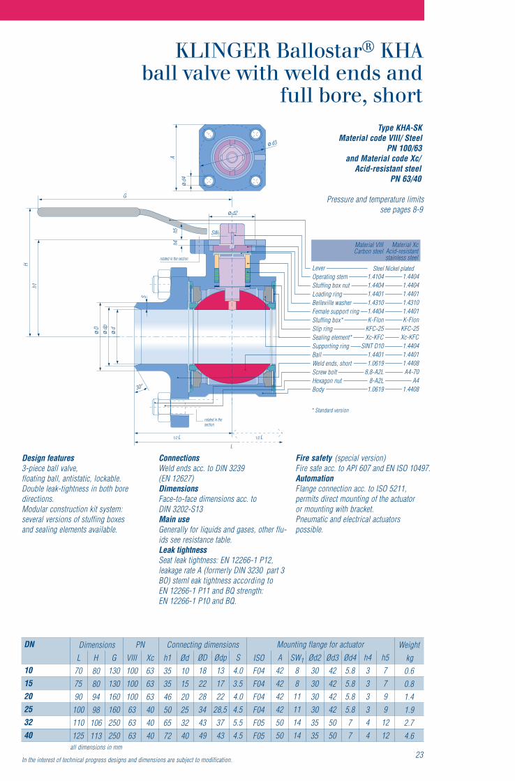
Design features3-piece ball valve,floating ball, antistatic, lockable.Double leak-tightness in both boredirections.Modular construction kit system:several versions of stuffing boxesand sealing elements available.
ConnectionsWeld ends acc. to DIN 3239(EN 12627)DimensionsFace-to-face dimensions acc. toDIN 3202-S13Main useGenerally for liquids and gases, other flu-ids see resistance table.Leak tightnessSeat leak tightness: EN 12266-1 P12,leakage rate A (formerly DIN 3230 part 3BO) steml eak tightness according toEN 12266-1 P11 and BQ strength:EN 12266-1 P10 and BQ.
Fire safety (special version)Fire safe acc. to API 607 and EN ISO 10497.AutomationFlange connection acc. to ISO 5211,permits direct mounting of the actuatoror mounting with bracket.Pneumatic and electrical actuatorspossible.
23all dimensions in mm
DN
101520253240
L707590
100110125
G130130160160250250
VIII100100100636363
Xc636363404040
h1353546506572
Ød101520253240
ISOF04F04F04F04F05F05
Weightkg0.60.81.41.92.74.6
H80809498
106113
Dimensions Connecting dimensionsPNh57799
1212
h4333344
Ød45.85.85.85.877
Ød3424242425050
Ød2303030303535
SW1
88
11111414
A424242425050
S4.03.54.04.55.54.5
Ødp131722
28,53743
ØD182228344349
Mounting flange for actuator
Type KHA-SKMaterial code VIII/ Steel
PN 100/63and Material code Xc/
Acid-resistant steelPN 63/40
Pressure and temperature limits
In the interest of technical progress designs and dimensions are subject to modification.
* Standard version
Steel Nickel plated
see pages 8-9
rotated in the section
Hh1
D d1 ddp
d2
30°
h4h5 SW
S
1
1/2 L 1/2 L
L
rotated in thesection
A
d3
d4
Material VIIICarbon steel
Material XcAcid-resistantstainless steel
1.41041.44041.44011.43101.4404K-Flon
KFC-25Xc-KFC
SINT D101.44011.0619
8,8-A2L8-A2L
1.0619
1.44041.44041.44011.43101.4404K-Flon
KFC-25Xc-KFC1.44041.44011.4408A4-70
A41.4408
LeverOperating stemStuffing box nutLoading ringBelleville washerFemale support ringStuffing box*Slip ringSealing element*Supporting ringBallWeld ends, longScrew boltHexagon nutBody
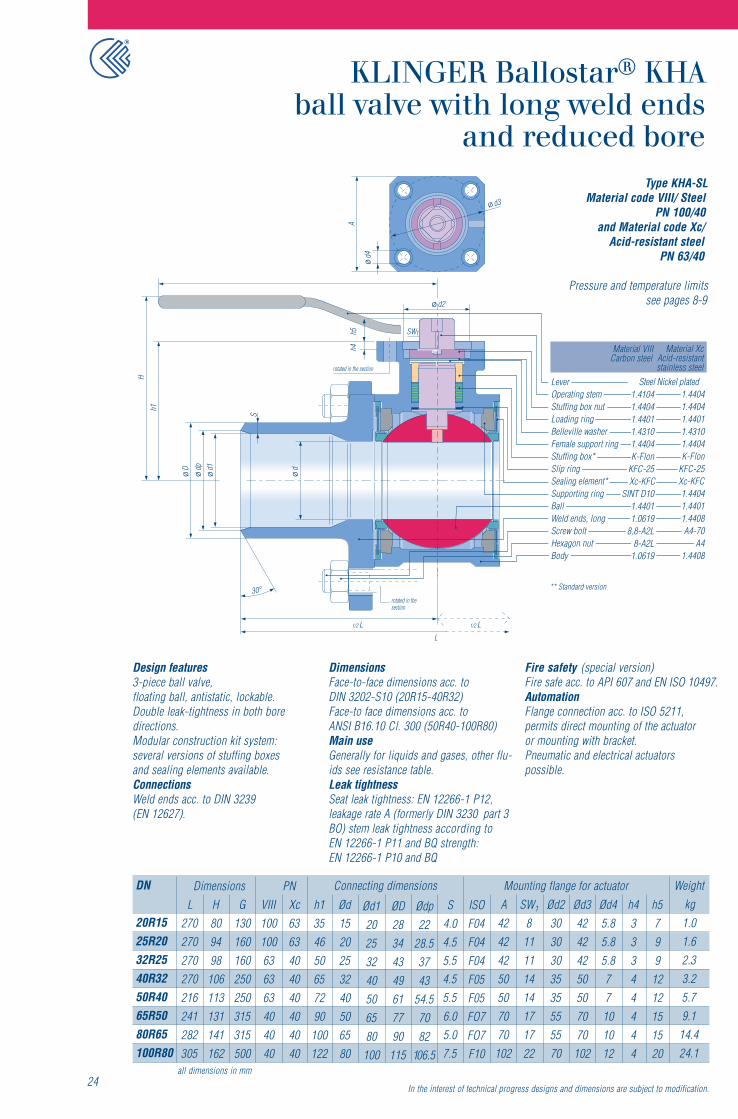
Design features3-piece ball valve,floating ball, antistatic, lockable.Double leak-tightness in both boredirections.Modular construction kit system:several versions of stuffing boxesand sealing elements available.ConnectionsWeld ends acc. to DIN 3239(EN 12627).
DimensionsFace-to-face dimensions acc. toDIN 3202-S10 (20R15-40R32)Face-to face dimensions acc. toANSI B16.10 Cl. 300 (50R40-100R80)Main useGenerally for liquids and gases, other flu-ids see resistance table.Leak tightnessSeat leak tightness: EN 12266-1 P12,leakage rate A (formerly DIN 3230 part 3BO) stem leak tightness according toEN 12266-1 P11 and BQ strength:EN 12266-1 P10 and BQ
Fire safety (special version)Fire safe acc. to API 607 and EN ISO 10497.AutomationFlange connection acc. to ISO 5211,permits direct mounting of the actuatoror mounting with bracket.Pneumatic and electrical actuatorspossible.
Type KHA-SLMaterial code VIII/ Steel
PN 100/40and Material code Xc/
Acid-resistant steelPN 63/40
Pressure and temperature limits
DN
20R1525R2032R2540R3250R4065R5080R65100R80
L270270270270216241282305
G130160160250250315315500
VIII100100636363404040
Xc6363404040404040
h1354650657290
100122
Ød1520253240506580
Ød120253240506580
100
ØD28344349617790
115
Ødp22
28.53743
54.57082
106.5
ISOF04F04F04F05F05FO7FO7F10
S4.04.55.54.55.56.05.07.5
Weightkg1.01.62.33.25.79.1
14.424.1
H809498
106113131141162
Dimensions Connecting dimensions
24
PN
all dimensions in mm
A42424250507070
102
SW1
811111414171722
Ød23030303535555570
Ød342424250507070
102
Ød45.85.85.877101012
h433344444
h5799
1212151520
Mounting flange for actuator
In the interest of technical progress designs and dimensions are subject to modification.
** Standard version
Steel Nickel plated
see pages 8-9
rotated in the section
Hh1
D d1 ddp
d2
G
30°
h4h5 SW
1/2 L 1/2 L
L
rotated in thesection
S
1
A
d3
d4
Material VIIICarbon steel
Material XcAcid-resistantstainless steel
1.41041.44041.44011.43101.4404K-Flon
KFC-25Xc-KFC
SINT D101.44011.0619
8,8-A2L8-A2L
1.0619
1.44041.44041.44011.43101.4404K-Flon
KFC-25Xc-KFC1.44041.44011.4408A4-70
A41.4408
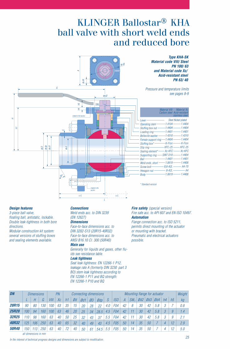
LeverOperating stemStuffing box nutLoading ringBelleville washerFemale support ringStuffing box*Slip ringSealing element*Supporting ringBallWeld ends, shortScrew boltHexagon nutBody
Design features3-piece ball valve,floating ball, antistatic, lockable.Double leak-tightness in both boredirections.Modular construction kit system:several versions of stuffing boxesand sealing elements available.
ConnectionsWeld ends acc. to DIN 3239(EN 12627)DimensionsFace-to-face dimensions acc. toDIN 3202-S13 (20R15-40R32)Face-to-face dimensions acc. toANSI B16.10 Cl. 300 (50R40)Main useGenerally for liquids and gases, other flu-ids see resistance table.Leak tightnessSeat leak tightness: EN 12266-1 P12,leakage rate A (formerly DIN 3230 part 3BO) stem leak tightness according toEN 12266-1 P11 and BQ strength:EN 12266-1 P10 and BQ
Fire safety (special version)Fire safe acc. to API 607 and EN ISO 10497.AutomationFlange connection acc. to ISO 5211,permits direct mounting of the actuatoror mounting with bracket.Pneumatic and electrical actuatorspossible.
Type KHA-SKMaterial code VIII/ Steel
PN 100/ 63and Material code Xc/
Acid-resistant steelPN 63/ 40
Pressure and temperature limits
all dimensions in mm25
DN
20R1525R2032R2540R3250R40
L90
100110125150
G130160160250250
VIII100100636363
Xc6363404040
h13546506572
Ød1520253240
Ød12025324050
ØD2834434961
Ødp22
28.53743
54.5
ISOF04F04F04F05F05
S4.04.55.54.55.5
Weightkg0.81.42.12.95.0
H809498
106113
Dimensions Connecting dimensionsPNA
4242425050
SW1
811111414
Ød23030303535
Ød34242425050
Ød45.85.85.877
h433344
h5799
1212
Mounting flange for actuator
In the interest of technical progress designs and dimensions are subject to modification.
* Standard version
KLINGER Ballostar KHAball valve with short weld ends
and reduced bore
Steel Nickel plated
see pages 8-9

Material IIIGrey cast ironrotated in the section
Hh1
SW2 d d1
d2
t1
G
h4h5
SW
1
1/2 1/2L L
L
rotated in thesection
A
d3
d4
1.41041.44041.44011.43101.4404K-Flon
KFC-25Xc-KFC
SINT D101.4401
EN-GJS-400-18LT8,8-A2L
8-A2L1.0619
LeverOperating stemStuffing box nutLoading ringBelleville washerFemale support ringStuffing box*Slip ringSealing element*Supporting ringBallThreaded connectionScrew boltHexagon nutBody
Design features3-piece ball valve,floating ball, antistatic, lockable.Double leak-tightness in both boredirections.Modular construction kit system:several versions of stuffing boxesand sealing elements available.
ConnectionsPipe thread acc. to DIN/ISO 228/1DimensionsFace-to-face dimensions acc. toDIN 3202-M3Main useGenerally for liquids and gases, other flu-ids see resistance table.Leak tightnessseat leak tightness: EN 12266-1 P12,leakage rate A (formerly DIN 3230 part 3BO) stem leak tightness according toEN 12266-1 P11 and BQ strength:EN 12266-1 P10 and BQ
AutomationFlange connection acc. to ISO 5211,permits direct mounting of the actuatoror mounting with bracket.Pneumatic and electrical actuatorspossible.
Type KHA-GMaterial code III/
Grey cast ironPN 16
Pressure and temperature limits
26
DN
1/2“ / R153/4“ / R151“ / R201 1/4“ / R2511/2“ / R322“ / R40
L758090
110120140
h1353546506572
G130130160160250250
ØdRP 1/2“RP 3/4“RP 1“
RP 1 1/4“RP 1 1/2“
RP 2“
Ød1151520253240
t114,51617212125
SW2
323241505570
ISOF04F04F04F04F05F05
A424242425050
SW1
88
11111414
Ød2303030303535
Ød3424242425050
Ød45.85.85.85.877
h4333344
h57799
1212
Weightkg0.60.71.31.92.64.5
H80809498
106113
Dimensions Connecting dimensions Mounting flange for actuatorPN
161616161616
all dimensions in mm or inch
In the interest of technical progress designs and dimensions are subject to modification.
* Standard version
Steel Nickel plated*
see pages 8-9

rotated in the section
Hh1
SW2 d d1
d2
t1
G
h4h5 SW1
1/2 L 1/2 L
L
rotated in thesection
A
d3
d4
Material VIIICarbon steel
Material XcAcid-resistantstainless steel
1.41041.44041.44011.43101.4404K-Flon
KFC-25Xc-KFC
SINT D101.44011.0619
8,8-A2L8-A2L
1.0619
1.44041.44041.44011.43101.4404K-Flon
KFC-25Xc-KFC1.44041.44011.4408A4-70
A41.4408
LeverOperating stemStuffing box nutLoading ringBelleville washerFemale support ringStuffing box*Slip ringSealing element*Supporting ringBallThreaded connectionScrew boltHexagon nutBody
Design features3-piece ball valve,floating ball, antistatic, lockable.Double leak-tightness in both boredirections.Modular construction kit system:several versions of stuffing boxesand sealing elements available.
ConnectionsPipe thread acc. to DIN/ISO 228/1DimensionsFace-to-face dimensions acc. toDIN 3202 Part 4 – M3Main useGenerally for liquids and gases, other flu-ids see resistance table.Leak tightnessSeat leak tightness: EN 12266-1 P12,leakage rate A (formerly DIN 3230 part 3BO) stem leak tightness according toEN 12266-1 P11 and BQ strength:EN 12266-1 P10 and BQ
Fire safety (special version).Fire safe acc. to API 607 and EN 10497.AutomationFlange connection acc. to ISO 5211,permits direct mounting of the actuatoror mounting with bracket.Pneumatic and electrical actuatorspossible.
Type KHA-GMaterial code VIII/ Steel
PN 100 – 63and Material code Xc/
Acid-resistant steelPN 63 – 40
Pressure and temperature limitssee pages 8-9
27
DN
3/4“ / R151“ / R201 1/4“ / R2511/2“ / R322“ / R40
L8090
110120140
h13546506572
G130160160250250
ØdRP 3/4“RP 1“
RP 1 1/4“RP 1 1/2“
RP 2“
Ød11520253240
t11617212125
SW2
3241505570
ISOF04F04F04F05F05
A4242425050
SW1
811111414
Ød23030303535
Ød34242425050
Ød45.85.85.877
h433344
h5799
1212
Weightkg
0.71.31.92.64.5
H809498
106113
Dimensions PN Connecting dimensions Mounting flange for actuator
VIII100100636363
Xc6363404040
all dimensions in mm or inch
In the interest of technical progress designs and dimensions are subject to modification.
* Standard version
Steel Nickel plated

rotated in the section
Hh1
d d1
d2
t1
G
h4
SW1
SW2
1/2 L 1/2 L
L
rotated in thesection
A
d3
d4
Material VIIICarbon steel
Material XcAcid-resistantstainless steel
1.40061.41041.44041.44011.43101.4404K-Flon
KFC-25Xc-KFC
SINT D101.44011.0619
8,8-A2L8-A2L
1.0619
1.40061.44041.44041.44011.43101.4404K-Flon
KFC-25Xc-KFC1.44041.44011.4408A4-70
A41.4408
h5
LeverOperating stemStuffing box nutLoading ringBelleville washerFemale support ringStuffing box*Slip ringSealing element*Supporting ringBallThreaded connectionScrew boltHexagon nutBody
Design features3-piece ball valve,floating ball, antistatic, lockable.Double leak-tightness in both boredirections.Modular construction kit system:several versions of stuffing boxesand sealing elements available.
ConnectionsPipe thread acc. to DIN/ISO 228/1DimensionsFace-to-face dimensions acc. toDIN 3202 Part 4 – M4Main useGenerally for liquids and gases, otherfluids see resistance table.Leak tightnessSeat leak tightness: EN 12266-1 P12,leakage rate A (formerly DIN 3230 part 3BO) stem leak tightness according toEN 12266-1 P11 and BQ strength:EN 12266-1 P10 and BQ
Fire safety (special version)Fire safe acc. to API 607 and EN ISO 10497.AutomationFlange connection acc. to ISO 5211,permits direct mounting of the actuatoror mounting with bracket.Pneumatic and electrical actuatorspossible.
Type KHA-GMaterial code VIII/ Steel
PN 100/40and Material code Xc/
Acid-resistant steelPN 63/40
Pressure and temperature limits
DN
3/8“1/2“3/4“1“1 1/4“1 1/2“2“
L758595
105120130150
G130130160160250250315
VIII10010010063636340
Xc63636340404040
h135354650657290
ØdRP 3/8“RP 1/2“RP 3/4“RP 1“
RP 1 1/4“RP 1 1/2“
RP 2“
Ød110152025324050
t111
14.51617212125
h57799
121215
h43333444
Ød4,5.85.85.85.87710
Ød342424242505070
Ød230303030353555
SW1
88
1111141417
A42424242505070
ISOF04F04F04F04F05F05FO7
Weightkg
0.70.81.52.12.94.77.4
H80809498
106113131
Dimensions Connecting dimensions Mounting flange for actuator
SW2
27323646556075
28
PN
all dimensions in mm or inch
In the interest of technical progress designs and dimensions are subject to modification.
* Standard version
see pages 8-9

29
Klinger Ballostar®KHA-FLC ball valves in cryogenic versionwith operating stem extension. Service media: Liquid gases
Klinger Ballostar®KHA ball valves with pneumatic actuatorsapplied in a steel mill. Service medium: Coke oven gas
KLINGER Ballostar KHA ball valves installed in an oil and gas®
refinery. Service media: C4-olefinsKLINGER KHA ball valves located in a heat supply line ofthe famous Islandic geothermal spa “Blue Lagoon”
KLINGER Ballostar®KHA ball valves located in a Swiss nuclearpower plant
Automated KLINGER Ballostar KHA ball valves applied in a®
Swedish chemical plant. Service medium: Heat transfer oil

30
% °C KFC-
25
PTFE
Met
al
III VIII
X c
A HCenotec 3 COCH3 20CenelytecA 2 H2
Air, dryOS(IAKAlum 4 )2 10 20OS(IAKAlum 4 )2 10 100
Aluminium acetate (CH3 COO)3AlAluminium ethylate Al(OC2H5)2
Aluminium chlorate Al(ClO3)3
Aluminium fluoride AlF3
Aluminium oxyde Al2 O3
HNa*inommA 3 10 20Ammonium hydroxyde NH4 OH 10 20Ammonium hydroxyde NH4 OH 10 100Ammonium bicarbonate (NH4)HCO3
Ammonium chloride NH4 Cl 5 20Ammonium chloride NH4 Cl 10 20Ammonium chloride NH4 Cl 10 100Ammonium chloride NH4 Cl 50 20Ammonium diphosphate (NH4)2 HPO4
Ammonium carbonate (NH4)2 CO3 KpAmmonium nitrate NH4 NO3 KpAmmonium sulphate (NH4)2 SO4 Kp
CAnilinie 6 H5 NH2
Recommendations in this tableshould help you to choose suitablematerials and types. We cannot assume aguarantee since the function and durabili-ty of the products are largely dependenton factors over which the manufacturerhas no influence.
In the event of specific conditions ofapproval, these must be observed. Pleasecontact us if in doubt. Wherever solids arenamed in the list, what is meant are theiraqueous solutions or suspensions.
Body material codes:
Material code IIIBody: Cast steelColour of body: Dark grey,phosphatedConnection: Grey cast ironInside parts: Corrosion resistant steel
Material code VIIIBody and connection: SteelColour of body: Dark grey,phosphatedInside parts: Corrosion resistant steel
Material code XcBody and connection:Acid-resistant steelColour of body: Bright, pickledInside parts: Acid-resistant steel
noitcennocdnaydoBrofslairetaMnoitartnecnoCalumroflacimehCdiulFand temperature seals (material code)
Vito
n
Names of materialsfor seals:
PTFE = KLINGER Flon® PTFEKFC-25 = KLINGER Flon®
carbon-reinforcedMetall = 1.4436 sealing ring coated
with STELLITEViton = Fluorinated rubber
* Stuffing box with special O-rings for this operating fluid: Please contact our sales team for additional information!
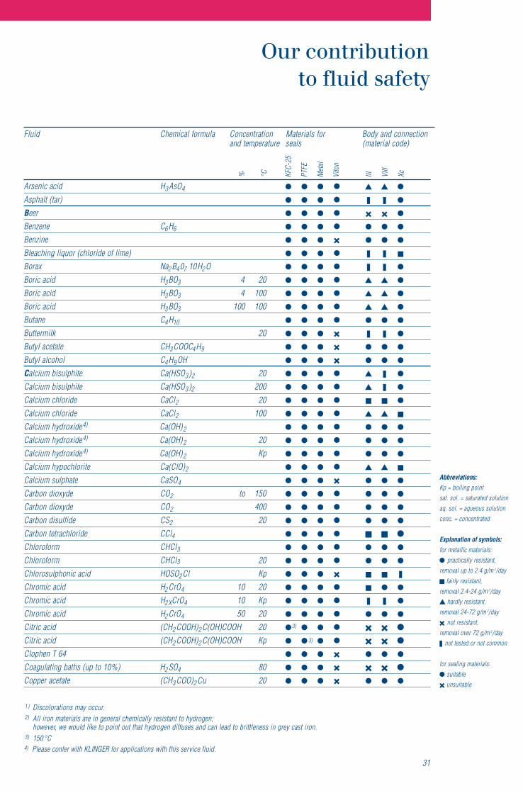
Abbreviations:Kp = boiling pointsat. sol. = saturated solutionaq. sol. = aqueous solutionconc. = concentrated
Explanation of symbols:for metallic materials:
practically resistant,removal up to 2.4 g/m 2/day
fairly resistant,removal 2.4-24 g/m 2/day
hardly resistant,removal 24-72 g/m 2/day
not resistant,removal over 72 g/m 2/day
not tested or not common
for sealing materials:suitableunsuitable
HdicacinesrA 3 AsO4
Asphalt (tar)Beer
CenezneB 6 H6
BenzineBleaching liquor (chloride of lime)
aNxaroB 2 B4 07 10H2 OHdicaciroB 3 BO3 4 20HdicaciroB 3 BO3 4 100HdicaciroB 3 BO3 100 100CenatuB 4 H10
02klimrettuBHCetatecalytuB 3 COOC4 H9
ClohoclalytuB 4 H9 OHCalcium bisulphite Ca(HSO3 )2 20Calcium bisulphite Ca(HSO3 )2 200Calcium chloride CaCl2 20Calcium chloride CaCl2 100Calcium hydroxide4) Ca(OH)2
Calcium hydroxide4) Ca(OH)2 20Calcium hydroxide4) Ca(OH)2 KpCalcium hypochlorite Ca(ClO)2
Calcium sulphate CaSO4
OCedyxoidnobraC 2 to 150OCedyxoidnobraC 2 400SCediflusidnobraC 2 20
Carbon tetrachloride CCl4lCHCmroforolhC 3
lCHCmroforolhC 3 20Chlorosulphonic acid HOSO2 Cl Kp
HdicacimorhC 2 CrO4 10 20HdicacimorhC 2XCrO4 10 KpHdicacimorhC 2 CrO4 50 20
HC(dicacirtiC 2 COOH)2 C(OH)COOH 20HC(dicacirtiC 2 COOH)2 C(OH)COOH Kp
Clophen T 64Coagulating baths (up to 10%) H2 SO4 80
HC(etatecareppoC 3 COO)2 Cu 20
31
% °C KFC-
25
PTFE
Met
al
III VIII
Xc
noitcennocdnaydoBrofslairetaMnoitartnecnoCalumroflacimehCdiulFand temperature seals (material code)
Vito
n
1 ) Discolorations may occur.2) All iron materials are in general chemically resistant to hydrogen;
however, we would like to point out that hydrogen diffuses and can lead to brittleness in grey cast iron.3) 150°C
3)
3)
4) Please confer with KLINGER for applications with this service fluid.

32
HC(etatecareppoC 3 COO)2 CU KpOSuCetahplusreppoC 4 20OSuCetahplusreppoC 4 Kp
D 02)dicaylkaew(htabnoitatozai08)dicaylkaew(htabnoitatozaiD02lioleseiD
DiphylDowtherm A
02lartuenroenilakla,rouqileyDpKlartuenroenilakla,rouqileyD02dicacinagro,rouqileyDpKdicacinagro,rouqileyD
Dye liquor, strongly sulphuric acid H2 SO4 over 0,3% 20Dye liquor, strongly sulphuric acid H2 SO4 over 0,3% KpDye liquor, weakly sulphuric acid H2 SO4 under 0,3% KpE Cenaht 2 H6
ClonahtE 2 H5 OHCrehtelyhtE 2 H5OC2 H6
HCetatecalyhtE 3COOC2 H5 KpCenelyhtE 2 H4
Ethylen chloride (dichlorethane) (CH2 Cl)2 20Fatty acids from C6
0204OHCHedyhedlamroFpK04OHCHedyhedlamroF0201HOOCHdicacimroF00101HOOCHdicacimroF02001HOOCHdicacimroF001001HOOCHdicacimroF
Freon 12, Frigen 12Glacial acetic acid CH3COOH 20Glacial acetic acid CH3COOH 10 20Glacial acetic acid CH3COOH 10 KpGlacial acetic acid CH3COOH 50 20Glacial acetic acid CH3COOH 50 KpGlacial acetic acid CH3COOH 80 20Glacial acetic acid CH3COOH 80 Kp
HC(enirecylG 2 OH2 ) CHOH 20HC(enirecylG 2 OH2 ) CHOH 100
02rageniveparGHeat transfer oils
02lCHyrd,dicacirolhcordyHHydrochloric acid, dry HCl 100
% °C KFC-
25
PTFE
Met
al
III VIII
X c
noitcennocdnaydoBrofslairetaMnoitartnecnoCalumroflacimehCdiulFand temperature seals (material code)
Vito
n

Hydroxylamine sulphate (NH2 OH)H2 SO4 10 20Hydroxylamine sulphate (NH2OH)H2 SO4 10 KpHydrochloric acid HCI 0,2 20Hydrochloric acid HCI 0,2 50Hydrochloric acid HCI 1 20Hydrogen sulphide, gas, dry H2 02SHydrogen sulphide, gas, wet H2 02S
HnegordyH 22)
Hydrogen peroxide H2O2 20Hydrogen peroxide H2O2 50Illuminating gasK 02etosoer
pKetosoerKLead acetate (lead sugar) Pb(CH3 COO)2 100 Kp
bPetanesradaeL 3 (AsO4)202liodeesniL001liodeesniL
Magnesium sulphate MgSO4 20Magnesium sulphate MgSO4 KpManganous chloride MnCl2 20Manganous chloride MnCl2 KpM.E.K. (Butanone) CH3 COC2 H5 Kp
02gHyrucreMMercury (II) chloride (sublimate) HgCl2 20Mercury (II) nitrate Hg(NO3)2 20
HClohoclalyhteM 3 OH 20 1) 1)
HClohoclalyhteM 3 OH Kp 1) 1)
Methylene chloride CH2 Cl2 20Methylene chloride CH2 Cl2 KpMilkN HCetatecamuirta 3 COONaNatural gas
ONHdicacirtiN 3 10 20ONHdicacirtiN 3 10 KpONHdicacirtiN 3 40 20ONHdicacirtiN 3 40 KpONHdicacirtiN 3 conc. 20ONHdicacirtiN 3 conc. Kp
33
% °C KFC-
25
PTFE
Met
al
III VIII
Xc
noitcennocdnaydoBrofslairetaMnoitartnecnoCalumroflacimehCdiulFand temperature seals (material code)
Vito
n
Abbreviations:Kp = boiling pointsat. sol. = saturated solutionaq. sol. = aqueous solutionconc. = concentrated
Explanation of symbols:for metallic materials:
practically resistant,removal up to 2.4 g/m 2/day
fairly resistant,removal 2.4-24 g/m 2/day
hardly resistant,removal 24-72 g/m 2/day
not resistant,removal over 72 g/m 2/day
not tested or not common
for sealing materials:suitableunsuitable
1 ) Discolorations may occur.2) All iron materials are in general chemically resistant to hydrogen;
however, we would like to point out that hydrogen diffuses and can lead to brittleness in grey cast iron.3) 150°C

34
NnegortiN 2
O 02)larenim,sliognitacirbul(sli02)elbategev(sliO
CdicacielO 17 H33 COOHHOOCHOOCdicacilaxO
OnegyxO 2 20P HCetatecalytne 3 COOC5 H11
02rehtemuelortePClonehP 6H5OHHdicacirohpsohP 3 PO4 10 20HdicacirohpsohP 3 PO4 10 KpHdicacirohpsohP 3 PO4 50 20HdicacirohpsohP 3 PO4 50 KpHdicacirohpsohP 3 PO4 80 20HdicacirohpsohP 3 PO4 80 Kp
Potassium acetate CH3 COOH KpPotassium carbonate K2 CO3 50 20Potassium carbonate K2 CO3 KpPotassium chlorate, at 100°, saturated sol. KClO3 KpPotassium chromium sulphate KCr(SO4)212H2 O 20Potassium chromium sulphate KCr(SO4)212H2 O KpPotassium cyanide solution KCN 5 20 3)
Potassium dichromate K2 Cr2 O7 25 20Potassium dichromate K2 Cr2 O7 KpPotassium hydrogentartrate COOH(CHOH)2COOK 20Potassium hydrogentartrate, at100°, sat. sol. COOH(CHOH)2COOK KpPotassium hydroxide KOH 25 20Potassium hydroxide KOH 25 KpPotassium hydroxide KOH 50 20Potassium hydroxide KOH 50 KpPotassium hydrochlorite KOCl 20Potassium hydrochlorite KOCl 40
pKjKedidoimuissatoPPotassium iodide KjPotassium nitrate KNO3 20Potassium nitrate KNO3 KpPotassium permanganate KMnO4 20Potassium permanganate KMnO4 Kp
CenaporP 3 H8 20S Cdicacilycila 6 H4 OHCOOH 20Salpeter
02lCaN)tlaskcor(tlaS
% °C KFC-
25
PTFE
Met
al
III VIII
X c
noitcennocdnaydoBrofslairetaMnoitartnecnoCalumroflacimehCdiulFand temperature seals (material code)
Vito
n

35
% °C KFC-
25
PTFE
Met
al
III VIII
Xc
noitcennocdnaydoBrofslairetaMnoitartnecnoCalumroflacimehCdiulFand temperature seals (material code)
Vito
n
Abbreviations:Kp = boiling pointsat. sol. = saturated solutionaq. sol. = aqueous solutionconc. = concentrated
Explanation of symbols:for metallic materials:
practically resistant,removal up to 2.4 g/m 2/day
fairly resistant,removal 2.4-24 g/m 2/day
hardly resistant,removal 24-72 g/m 2/day
not resistant,removal over 72 g/m 2/day
not tested or not common
for sealing materials:suitableunsuitable
1 ) Discolorations may occur.2) All iron materials are in general chemically resistant to hydrogen;
however, we would like to point out that hydrogen diffuses and can lead to brittleness in grey cast iron.3) 150°C
02retawaeSpKretawaeS
Silicone oilSoapSodium carbonate (soda solution, cold sat.) Na2 CO3 20Sodium carbonate (soda solution) Na2 CO3 KpSodium hydroxide NaOH 20 20Sodium hydroxide NaOH 20 KpSodium hydroxide NaOH 35 20Sodium hydroxide NaOH 35 KpSodium sulphate Na2 SO4
Starch solutionSteam 3)
CdicaciraetS 17 H35COOH02raguS08raguS
OSH(aCeyletihpluS 3)2 20(fresh cooking liquor, spent liquor) Ca(HSO3)2 80
OSedixoidruhpluS 2
HdicaciruhpluS 2 SO4 1 20HdicaciruhpluS 2 SO4 10 20HdicaciruhpluS 2 SO4 90 20HdicaciruhpluS 2 SO4 conc. 20
Sulphurous acid H2 SO3
T Cdicacinna 76 H52 O46 10 20CdicacinnaT 76 H52 O46 10 KpCdicacinnaT 76 H52 O46 50 20
081raT)HOOCHOHC(dicaciratraT 2 20
CeneuloT 6 H5 CH3 20CenelyhterolhcirT 2 HCl3
02lioenitnepruTU HN(aer 2 )2 CO 20Water (fresh and drinking water) H2OWater glass (K- and Na-silicate) K2 SiO3 Na2 HCl3X Cenely 6 H4 (CH3)2 20

KLINGER Fluid Control GmbHA-2352 Gumpoldskirchen, AustriaPostfach 19, Am Kanal 8–10Tel. +43 (0)2252-600-0Fax +43 (0)2252-600-100e-mail: [email protected]
KHA
eng
9/10
KLINGER product range
K
L
I
N
G
E
R
ey role
ink
nnovation
avigation
rowth
fficiency
outine
Product range KLINGER Ball-o-top
Piston valves KVN
Brass ball valves
made of grey cast iron, nodular castiron, steel or stainless steel
KLINGERMATIC®
Reflex and transparentgauge glasses
Circular sight-glasses
AB cocks
Actuator for piston valves and ballvalves
Packing-sleeve cocks and pressure-gauge cocks in brass, steel andstainless steel
Ballostar® KHA
Ballostar® KHI
KLINGER Monoball®
3-piece ball valve made of grey castiron, steel or stainless steel
2-piece ball valve with trunnionmounted ball, made of grey castiron, steel or stainless steel
2-piece ball valve with floating ball,made of steel or stainless steel
One-piece fully welded ball valvemade of casted steel
One-piece ball valve made ofsteel
Ballostar® KHE
Monolith KHO