Embed Size (px)
Citation preview

EN Manual
iso685-D_D00022_06_M_XXEN/04.2017
ISOMETER® iso685-Diso685W-Diso685-Siso685W-S
Insulation Monitoring Device for IT AC systemswith galvanically connected rectifiers and inverters and for IT DC systems

Bender GmbH & Co. KGPostfach 1161 • 35301 Gruenberg • GermanyLondorfer Straße 65 • 35305 Gruenberg • Germany
Tel.: +49 6401 807-0Fax: +49 6401 807-259
E-Mail: [email protected]: www.bender.de
© Bender GmbH & Co. KGAll rights reserved.
Reproduction only with permissionof the publisher.
Subject to change.
Customer serviceService-Hotline: 0700-BenderHelp (Telephone and Fax)Carl-Benz-Straße 8 • 35305 Gruenberg • Germany
Tel.:+49 6401 807-760Fax:+49 6401 807-629
E-Mail:[email protected]
PLEASE READ THIS MANUAL AND ANY ACCOMPANYING DOCUMENTS CAREFULLY AND KEEP THEM IN A SECURE PLACE FOR FUTURE REFERENCE.

T
3 iso685-D_D00022_06_M_XXEN/04.2017
1
2
3
4
...........................................................................16ions . . . . . . . . . . . . . . . . . . . . . . . . . . . . . . . . . . . . . . . . . . . . . . .16
. . . . . . . . . . . . . . . . . . . . . . . . . . . . . . . . . . . . . . . . . . . . . . . . . . .16
g. . . . . . . . . . . . . . . . . . . . . . . . . . . . . . . . . . . . . . . . . . . . . . . . . .17
...........................................................................17irements . . . . . . . . . . . . . . . . . . . . . . . . . . . . . . . . . . . . . . . . . .17
3(N)AC system. . . . . . . . . . . . . . . . . . . . . . . . . . . . . . . . . . . . .19
n AC system . . . . . . . . . . . . . . . . . . . . . . . . . . . . . . . . . . . . . . .19
DC system. . . . . . . . . . . . . . . . . . . . . . . . . . . . . . . . . . . . . . . . .20
e X1 interface . . . . . . . . . . . . . . . . . . . . . . . . . . . . . . . . . . . . .20
e supply voltage . . . . . . . . . . . . . . . . . . . . . . . . . . . . . . . . . .21
e Ethernet interface . . . . . . . . . . . . . . . . . . . . . . . . . . . . . . .21
e relay 1 interface (11 12 14) . . . . . . . . . . . . . . . . . . . . . .22
e relay 2 interface (21 22 24) . . . . . . . . . . . . . . . . . . . . . .22
...........................................................................23mmissioning process . . . . . . . . . . . . . . . . . . . . . . . . . . . . . .23
ning . . . . . . . . . . . . . . . . . . . . . . . . . . . . . . . . . . . . . . . . . . . . . .24
e . . . . . . . . . . . . . . . . . . . . . . . . . . . . . . . . . . . . . . . . . . . . . . . . . .24
date . . . . . . . . . . . . . . . . . . . . . . . . . . . . . . . . . . . . . . . . . . . . . .24
ype . . . . . . . . . . . . . . . . . . . . . . . . . . . . . . . . . . . . . . . . . . . . . . .24
pling device . . . . . . . . . . . . . . . . . . . . . . . . . . . . . . . . . . . . . . .24
. . . . . . . . . . . . . . . . . . . . . . . . . . . . . . . . . . . . . . . . . . . . . . . . . . . .24
value Ran1 for Alarm 1 . . . . . . . . . . . . . . . . . . . . . . . . . . .25
value Ran2 for Alarm 2 . . . . . . . . . . . . . . . . . . . . . . . . . . .25
g. . . . . . . . . . . . . . . . . . . . . . . . . . . . . . . . . . . . . . . . . . . . . . . . . .25
able of contents
. Important information .................................................................... 61.1 How to use this manual . . . . . . . . . . . . . . . . . . . . . . . . . . . . . . . . . . . . . . . . . . . . . 6
1.2 Technical support . . . . . . . . . . . . . . . . . . . . . . . . . . . . . . . . . . . . . . . . . . . . . . . . . . 6
1.2.1 First level support . . . . . . . . . . . . . . . . . . . . . . . . . . . . . . . . . . . . . . . . . . . . . . 6
1.2.2 Repair service . . . . . . . . . . . . . . . . . . . . . . . . . . . . . . . . . . . . . . . . . . . . . . . . . . 6
1.2.3 Field service . . . . . . . . . . . . . . . . . . . . . . . . . . . . . . . . . . . . . . . . . . . . . . . . . . . . 7
1.3 Training courses . . . . . . . . . . . . . . . . . . . . . . . . . . . . . . . . . . . . . . . . . . . . . . . . . . . . 7
1.4 Delivery conditions . . . . . . . . . . . . . . . . . . . . . . . . . . . . . . . . . . . . . . . . . . . . . . . . . 7
1.5 Storage . . . . . . . . . . . . . . . . . . . . . . . . . . . . . . . . . . . . . . . . . . . . . . . . . . . . . . . . . . . . 7
1.6 Disposal. . . . . . . . . . . . . . . . . . . . . . . . . . . . . . . . . . . . . . . . . . . . . . . . . . . . . . . . . . . . 7
. Safety instructions ............................................................................ 82.1 General safety instructions . . . . . . . . . . . . . . . . . . . . . . . . . . . . . . . . . . . . . . . . . . 8
2.2 Work activities on electrical installations. . . . . . . . . . . . . . . . . . . . . . . . . . . . . 8
2.3 Device-specific safety information . . . . . . . . . . . . . . . . . . . . . . . . . . . . . . . . . . 8
2.4 Intended use . . . . . . . . . . . . . . . . . . . . . . . . . . . . . . . . . . . . . . . . . . . . . . . . . . . . . . . 9
. Function ........................................................................................... 103.1 Features. . . . . . . . . . . . . . . . . . . . . . . . . . . . . . . . . . . . . . . . . . . . . . . . . . . . . . . . . . . 10
3.2 Product description . . . . . . . . . . . . . . . . . . . . . . . . . . . . . . . . . . . . . . . . . . . . . . . 10
3.2.1 General product description . . . . . . . . . . . . . . . . . . . . . . . . . . . . . . . . . . . 10
3.2.2 Special characteristics of ISOMETER® iso685-S with front panel . . 10
3.3 Functional description . . . . . . . . . . . . . . . . . . . . . . . . . . . . . . . . . . . . . . . . . . . . . 10
3.4 Interfaces . . . . . . . . . . . . . . . . . . . . . . . . . . . . . . . . . . . . . . . . . . . . . . . . . . . . . . . . . 11
3.5 Self test . . . . . . . . . . . . . . . . . . . . . . . . . . . . . . . . . . . . . . . . . . . . . . . . . . . . . . . . . . . 11
. Device overview .............................................................................. 124.1 Dimensions . . . . . . . . . . . . . . . . . . . . . . . . . . . . . . . . . . . . . . . . . . . . . . . . . . . . . . . 12
4.2 Device variants . . . . . . . . . . . . . . . . . . . . . . . . . . . . . . . . . . . . . . . . . . . . . . . . . . . . 13
4.3 Connections and panel . . . . . . . . . . . . . . . . . . . . . . . . . . . . . . . . . . . . . . . . . . . . 14
4.4 Display elements and device buttons . . . . . . . . . . . . . . . . . . . . . . . . . . . . . . 15
5. Mounting ...............5.1 General instruct
5.2 Screw mounting
5.3 DIN rail mountin
6. Connection ............6.1 Connection requ
6.2 Connection to a
6.3 Connection to a
6.4 Connection to a
6.5 Connection to th
6.6 Connection to th
6.7 Connection to th
6.8 Connection to th
6.9 Connection to th
7. Commissioning ....7.1 General initial co
7.2 Initial commissio
7.2.1 Set languag
7.2.2 Set time and
7.2.3 Set system t
7.2.4 Select a cou
7.2.5 Set profile .
7.2.6 Set response
7.2.7 Set response
7.3 Recommissionin

T
iso685-D_D00022_06_M_XXEN/04.20174
8
9
1
igital 2 . . . . . . . . . . . . . . . . . . . . . . . . . . . . . . . . . . . . . . . . . . . 35igital 3 . . . . . . . . . . . . . . . . . . . . . . . . . . . . . . . . . . . . . . . . . . . 35tputs . . . . . . . . . . . . . . . . . . . . . . . . . . . . . . . . . . . . . . . . . . . . . 35 Relay 1 . . . . . . . . . . . . . . . . . . . . . . . . . . . . . . . . . . . . . . . . . . . 35.1) TEST . . . . . . . . . . . . . . . . . . . . . . . . . . . . . . . . . . . . . . . . . . 35.2) Relay mode . . . . . . . . . . . . . . . . . . . . . . . . . . . . . . . . . . . 35.3) Function 1 . . . . . . . . . . . . . . . . . . . . . . . . . . . . . . . . . . . . 35.4) Function 2 . . . . . . . . . . . . . . . . . . . . . . . . . . . . . . . . . . . . 36.5) Function 3 . . . . . . . . . . . . . . . . . . . . . . . . . . . . . . . . . . . . 36 Relay 2 . . . . . . . . . . . . . . . . . . . . . . . . . . . . . . . . . . . . . . . . . . . 36 Digital 1. . . . . . . . . . . . . . . . . . . . . . . . . . . . . . . . . . . . . . . . . . 36.1) TEST . . . . . . . . . . . . . . . . . . . . . . . . . . . . . . . . . . . . . . . . . . 36.2) Mode . . . . . . . . . . . . . . . . . . . . . . . . . . . . . . . . . . . . . . . . . 36.3) Function 1 . . . . . . . . . . . . . . . . . . . . . . . . . . . . . . . . . . . . 36.4) Function 2 . . . . . . . . . . . . . . . . . . . . . . . . . . . . . . . . . . . . 36.5) Function 3 . . . . . . . . . . . . . . . . . . . . . . . . . . . . . . . . . . . . 36 Digital 2. . . . . . . . . . . . . . . . . . . . . . . . . . . . . . . . . . . . . . . . . . 37 Buzzer . . . . . . . . . . . . . . . . . . . . . . . . . . . . . . . . . . . . . . . . . . . 37.1) TEST . . . . . . . . . . . . . . . . . . . . . . . . . . . . . . . . . . . . . . . . . . 37.2) Function 1 . . . . . . . . . . . . . . . . . . . . . . . . . . . . . . . . . . . . 37.3) Function 2 . . . . . . . . . . . . . . . . . . . . . . . . . . . . . . . . . . . . 37.4) Function 3 . . . . . . . . . . . . . . . . . . . . . . . . . . . . . . . . . . . . 37 Analogue . . . . . . . . . . . . . . . . . . . . . . . . . . . . . . . . . . . . . . . . 37.1) Mode . . . . . . . . . . . . . . . . . . . . . . . . . . . . . . . . . . . . . . . . . 37.2) Midscale . . . . . . . . . . . . . . . . . . . . . . . . . . . . . . . . . . . . . . 37.3) TEST . . . . . . . . . . . . . . . . . . . . . . . . . . . . . . . . . . . . . . . . . . 38.4) Function . . . . . . . . . . . . . . . . . . . . . . . . . . . . . . . . . . . . . . 38measured values . . . . . . . . . . . . . . . . . . . . . . . . . . . . . . . . . .38rol . . . . . . . . . . . . . . . . . . . . . . . . . . . . . . . . . . . . . . . . . . . . . . . . .38ry . . . . . . . . . . . . . . . . . . . . . . . . . . . . . . . . . . . . . . . . . . . . . . . . .38
10.1 (5.0) Device settings . . . . . . . . . . . . . . . . . . . . . . . . . . . . . . . . . . . . . . . . .39guage . . . . . . . . . . . . . . . . . . . . . . . . . . . . . . . . . . . . . . . . . . . . 39k . . . . . . . . . . . . . . . . . . . . . . . . . . . . . . . . . . . . . . . . . . . . . . . . . 39ime . . . . . . . . . . . . . . . . . . . . . . . . . . . . . . . . . . . . . . . . . . . . . . 39ormat (time). . . . . . . . . . . . . . . . . . . . . . . . . . . . . . . . . . . . . . 39ummer time. . . . . . . . . . . . . . . . . . . . . . . . . . . . . . . . . . . . . . 39ate . . . . . . . . . . . . . . . . . . . . . . . . . . . . . . . . . . . . . . . . . . . . . . 39ormat (date). . . . . . . . . . . . . . . . . . . . . . . . . . . . . . . . . . . . . . 39TP . . . . . . . . . . . . . . . . . . . . . . . . . . . . . . . . . . . . . . . . . . . . . . . 39TP server. . . . . . . . . . . . . . . . . . . . . . . . . . . . . . . . . . . . . . . . . 39
10.1 (1.6) Device . . . . . . . . . . . . . . . . . . . . . . . . . . . . . . . . . . . . . . . . . . . . . . . 3310.1 (1.7) T(Start). . . . . . . . . . . . . . . . . . . . . . . . . . . . . . . . . . . . . . . . . . . . . . . 3310.1 (1.8) Coupling monitoring . . . . . . . . . . . . . . . . . . . . . . . . . . . . . . . . . 3310.1 (1.9) Inputs . . . . . . . . . . . . . . . . . . . . . . . . . . . . . . . . . . . . . . . . . . . . . . . 34
10.1 (1.9.1) Digital 1 . . . . . . . . . . . . . . . . . . . . . . . . . . . . . . . . . . . . . . . . . . 3410.1 (1.9.1.1) Mode . . . . . . . . . . . . . . . . . . . . . . . . . . . . . . . . . . . . . . . . . . 3410.1 (1.9.1.2) t(on) . . . . . . . . . . . . . . . . . . . . . . . . . . . . . . . . . . . . . . . . . . . 3410.1 (1.9.1.3) t(off) . . . . . . . . . . . . . . . . . . . . . . . . . . . . . . . . . . . . . . . . . . . 3410.1 (1.9.1.4) Function . . . . . . . . . . . . . . . . . . . . . . . . . . . . . . . . . . . . . . . 34
10.1 (5.1) Lan10.1 (5.2) Cloc
10.1 (5.2.1) T10.1 (5.2.2) F10.1 (5.2.3) S10.1 (5.2.4) D10.1 (5.2.5) F10.1 (5.2.6) N10.1 (5.2.7) N
Table of contentsable of contents
. Display .............................................................................................. 268.1 Standard display. . . . . . . . . . . . . . . . . . . . . . . . . . . . . . . . . . . . . . . . . . . . . . . . . . . 26
8.2 Fault display (active) . . . . . . . . . . . . . . . . . . . . . . . . . . . . . . . . . . . . . . . . . . . . . . . 26
8.3 Fault display (inactive) . . . . . . . . . . . . . . . . . . . . . . . . . . . . . . . . . . . . . . . . . . . . . 27
8.4 Acknowledge fault memory. . . . . . . . . . . . . . . . . . . . . . . . . . . . . . . . . . . . . . . . 28
8.5 Data-isoGraph. . . . . . . . . . . . . . . . . . . . . . . . . . . . . . . . . . . . . . . . . . . . . . . . . . . . . 28
8.6 History memory . . . . . . . . . . . . . . . . . . . . . . . . . . . . . . . . . . . . . . . . . . . . . . . . . . . 29
8.7 Initial measurement . . . . . . . . . . . . . . . . . . . . . . . . . . . . . . . . . . . . . . . . . . . . . . . 29
. Menu ................................................................................................. 309.1 Menu structure . . . . . . . . . . . . . . . . . . . . . . . . . . . . . . . . . . . . . . . . . . . . . . . . . . . . 30
9.2 Operating and navigating . . . . . . . . . . . . . . . . . . . . . . . . . . . . . . . . . . . . . . . . . 31
9.2.1 Easy operation . . . . . . . . . . . . . . . . . . . . . . . . . . . . . . . . . . . . . . . . . . . . . . . . 31
0. Settings .......................................................................................... 3210.1 Settings in the device menu . . . . . . . . . . . . . . . . . . . . . . . . . . . . . . . . . . . . . . 32
10.1 (1.0) Alarm settings . . . . . . . . . . . . . . . . . . . . . . . . . . . . . . . . . . . . . . . . 3210.1 (1.1) Insulation alarm . . . . . . . . . . . . . . . . . . . . . . . . . . . . . . . . . . . . . . 32
10.1 (1.1.1) Alarm 1 . . . . . . . . . . . . . . . . . . . . . . . . . . . . . . . . . . . . . . . . . . . 3210.1 (1.1.2) Alarm 2 . . . . . . . . . . . . . . . . . . . . . . . . . . . . . . . . . . . . . . . . . . . 3210.1 (1.1.3) Fault memory . . . . . . . . . . . . . . . . . . . . . . . . . . . . . . . . . . . . . 32
10.1 (1.2) DC alarm. . . . . . . . . . . . . . . . . . . . . . . . . . . . . . . . . . . . . . . . . . . . . 3210.1 (1.2.1) Alarm . . . . . . . . . . . . . . . . . . . . . . . . . . . . . . . . . . . . . . . . . . . . . 3210.1 (1.2.2) U(DC-E) . . . . . . . . . . . . . . . . . . . . . . . . . . . . . . . . . . . . . . . . . . . 32
10.1 (1.3) Profile . . . . . . . . . . . . . . . . . . . . . . . . . . . . . . . . . . . . . . . . . . . . . . . 3310.1 (1.4) System type. . . . . . . . . . . . . . . . . . . . . . . . . . . . . . . . . . . . . . . . . . 3310.1 (1.5) Coupling. . . . . . . . . . . . . . . . . . . . . . . . . . . . . . . . . . . . . . . . . . . . . 33
10.1 (1.9.2) D10.1 (1.9.3) D
10.1 (1.10) Ou10.1 (1.10.1)
10.1 (1.10.110.1 (1.10.110.1 (1.10.110.1 (1.10.110.1 (1.10.1
10.1 (1.10.2) 10.1 (1.10.3)
10.1 (1.10.310.1 (1.10.310.1 (1.10.310.1 (1.10.310.1 (1.10.3
10.1 (1.10.4) 10.1 (1.10.5)
10.1 (1.10.510.1 (1.10.510.1 (1.10.510.1 (1.10.5
10.1 (1.10.6) 10.1 (1.10.610.1 (1.10.610.1 (1.10.610.1 (1.10.6
10.1 (2.0) Data 10.1 (3.0) Cont10.1 (4.0) Histo

T
iso685-D_D00022_06_M_XXEN/04.20175
11. Device communication ............................................................... 42
1
...........................................................................48ng the AGH150W-4(DC) . . . . . . . . . . . . . . . . . . . . . . . . . . .49
ng the AGH150W-4 (3(N)AC) . . . . . . . . . . . . . . . . . . . . . . .50
ng theAGH204S-4. . . . . . . . . . . . . . . . . . . . . . . . . . . . . . . . . .51
tion using the AGH520S . . . . . . . . . . . . . . . . . . . . . . . . . . . .52
n using the AGH520S. . . . . . . . . . . . . . . . . . . . . . . . . . . . . . .53
ng the AGH676S-4 . . . . . . . . . . . . . . . . . . . . . . . . . . . . . . . . .54
...........................................................................55 profile power circuits . . . . . . . . . . . . . . . . . . . . . . . . . . . . . .55
profile control circuits . . . . . . . . . . . . . . . . . . . . . . . . . . . . .55
profile generator . . . . . . . . . . . . . . . . . . . . . . . . . . . . . . . . . .56
profile high capacitance . . . . . . . . . . . . . . . . . . . . . . . . . . .56
profile inverter > 10 Hz . . . . . . . . . . . . . . . . . . . . . . . . . . . .57
profile inverter < 10 Hz . . . . . . . . . . . . . . . . . . . . . . . . . . . .57
DC alarm . . . . . . . . . . . . . . . . . . . . . . . . . . . . . . . . . . . . . . . . . .58
ainty . . . . . . . . . . . . . . . . . . . . . . . . . . . . . . . . . . . . . . . . . . . . . .58
...........................................................................59
...........................................................................60
...........................................................................61
. . . . . . . . . . . . . . . . . . . . . . . . . . . . . . . . . . . . . . . . . . . . . . . . . . . .61
. . . . . . . . . . . . . . . . . . . . . . . . . . . . . . . . . . . . . . . . . . . . . . . . . . . .64
17.3 Standards and certifications. . . . . . . . . . . . . . . . . . . . . . . . . . . . . . . . . . . . . . .64
ls . . . . . . . . . . . . . . . . . . . . . . . . . . . . . . . . . . . . . . . . . . . . . . . . . .65
...........................................................................66
...........................................................................67
11.1 Ethernet interface . . . . . . . . . . . . . . . . . . . . . . . . . . . . . . . . . . . . . . . . . . . . . . . . 42
11.2 BCOM. . . . . . . . . . . . . . . . . . . . . . . . . . . . . . . . . . . . . . . . . . . . . . . . . . . . . . . . . . . . 42
11.3 Modbus TCP . . . . . . . . . . . . . . . . . . . . . . . . . . . . . . . . . . . . . . . . . . . . . . . . . . . . . 42
11.4 Web server . . . . . . . . . . . . . . . . . . . . . . . . . . . . . . . . . . . . . . . . . . . . . . . . . . . . . . . 43
11.5 BS bus . . . . . . . . . . . . . . . . . . . . . . . . . . . . . . . . . . . . . . . . . . . . . . . . . . . . . . . . . . . 46
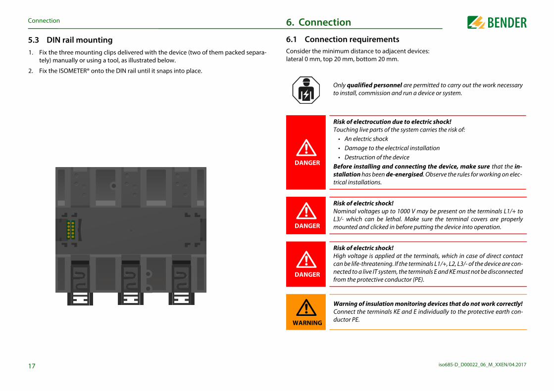
2. Device profiles .............................................................................. 47
17.4 Ordering detai
18. Glossary ...............
Index .............................
Table of contentsable of contents
10.1 (5.2.8) UTC. . . . . . . . . . . . . . . . . . . . . . . . . . . . . . . . . . . . . . . . . . . . . . . 4010.1 (5.3) Interface . . . . . . . . . . . . . . . . . . . . . . . . . . . . . . . . . . . . . . . . . . . . . 40
10.1 (5.3.1) Write access. . . . . . . . . . . . . . . . . . . . . . . . . . . . . . . . . . . . . . . 4010.1 (5.3.2) Ethernet . . . . . . . . . . . . . . . . . . . . . . . . . . . . . . . . . . . . . . . . . . 40
10.1 (5.3.2.1) DHCP . . . . . . . . . . . . . . . . . . . . . . . . . . . . . . . . . . . . . . . . . . 4010.1 (5.3.2.2) IP . . . . . . . . . . . . . . . . . . . . . . . . . . . . . . . . . . . . . . . . . . . . . . 4010.1 (5.3.2.3) SN . . . . . . . . . . . . . . . . . . . . . . . . . . . . . . . . . . . . . . . . . . . . . 4010.1 (5.3.2.4) Std. GW . . . . . . . . . . . . . . . . . . . . . . . . . . . . . . . . . . . . . . . . 4010.1 (5.3.2.5) DNS server . . . . . . . . . . . . . . . . . . . . . . . . . . . . . . . . . . . . . 4010.1 (5.3.2.6) Domain . . . . . . . . . . . . . . . . . . . . . . . . . . . . . . . . . . . . . . . . 40
10.1 (5.3.3) BCOM. . . . . . . . . . . . . . . . . . . . . . . . . . . . . . . . . . . . . . . . . . . . . 4010.1 (5.3.3.1) System name . . . . . . . . . . . . . . . . . . . . . . . . . . . . . . . . . . 4010.1 (5.3.3.2) Subsystem . . . . . . . . . . . . . . . . . . . . . . . . . . . . . . . . . . . . . 4010.1 (5.3.3.3) Device address. . . . . . . . . . . . . . . . . . . . . . . . . . . . . . . . . 4010.1 (5.3.3.4) Timeout . . . . . . . . . . . . . . . . . . . . . . . . . . . . . . . . . . . . . . . 4010.1 (5.3.3.5) TTL for subscription . . . . . . . . . . . . . . . . . . . . . . . . . . . . 40
10.1 (5.3.4) Modbus TCP . . . . . . . . . . . . . . . . . . . . . . . . . . . . . . . . . . . . . . 4110.1 (5.3.4.1) Port 502 . . . . . . . . . . . . . . . . . . . . . . . . . . . . . . . . . . . . . . . 41
10.1 (5.3.5) BS bus . . . . . . . . . . . . . . . . . . . . . . . . . . . . . . . . . . . . . . . . . . . . 4110.1 (5.3.5.1) Address. . . . . . . . . . . . . . . . . . . . . . . . . . . . . . . . . . . . . . . . 41
10.1 (5.4) Display. . . . . . . . . . . . . . . . . . . . . . . . . . . . . . . . . . . . . . . . . . . . . . . 4110.1 (5.4.1) Brightness . . . . . . . . . . . . . . . . . . . . . . . . . . . . . . . . . . . . . . . . 41
10.1 (5.5) Password . . . . . . . . . . . . . . . . . . . . . . . . . . . . . . . . . . . . . . . . . . . . 4110.1 (5.5.1) Password . . . . . . . . . . . . . . . . . . . . . . . . . . . . . . . . . . . . . . . . . 4110.1 (5.5.2) Status. . . . . . . . . . . . . . . . . . . . . . . . . . . . . . . . . . . . . . . . . . . . . 41
10.1 (5.6) Commissioning . . . . . . . . . . . . . . . . . . . . . . . . . . . . . . . . . . . . . . 4110.1 (5.7) Data backup . . . . . . . . . . . . . . . . . . . . . . . . . . . . . . . . . . . . . . . . . 4110.1 (5.8) Service. . . . . . . . . . . . . . . . . . . . . . . . . . . . . . . . . . . . . . . . . . . . . . . 41
10.1 (6.0) Info . . . . . . . . . . . . . . . . . . . . . . . . . . . . . . . . . . . . . . . . . . . . . . . . . . . . 41
13. Coupling devices 13.1 Connection usi
13.2 Connection usi
13.3 Connection usi
13.4 3(N)AC connec
13.5 3AC connectio
13.6 Connection usi
14. Diagrams .............14.1 Response time
14.2 Response time
14.3 Response time
14.4 Response time
14.5 Response time
14.6 Response time
14.7 Response time
14.8 Relative uncert
15. Alarm messages .
16. Factory settings ..
17. Technical data ....17.1 Tabular data . .
17.2 Option "W" . . .

iso685-D_D00022_06_M_XXEN/04.2017
1
1
AThth
rtbleshooting Bender offers you:
rt or e-mail for all Bender products
pecific customer applications
401 807-760*401 807-259enderHelp (Tel. and Fax)[email protected]
nd replacement service for Bender products
esting and analysing Bender products
update for Bender devices
t devices in the event of faulty or incorrectly delivered Ben-
Bender devices, which includes an in-house repair service or no extra cost
401 807-780** (technical issues)401 807-784**, -785** (sales)401 [email protected]
epair to the following address:
e,
6
This symbol denotes information intended to assist the user in makingoptimum use of the product.
Please send the devices for r
Bender GmbH, Repair-ServicLondorfer Strasse 65,35305 Grünberg
Important information. Important information
.1 How to use this manual
lways keep this manual within easy reach for future reference.o make it easier for you to understand and revisit certain sections in this manual, we ave used symbols to identify important instructions and information. The meaning of ese symbols is explained below:
This manual is intended for qualified personnel working in electrical en-gineering and electronics!
This signal word indicates that there is a high risk of danger that will re-sult in electrocution or serious injury if not avoided.
This signal word indicates a medium risk of danger that can lead todeath or serious injury if not avoided.
This signal word indicates a low level risk that can result in minor or mo-derate injury or damage to property if not avoided.
DANGER
WARNING
CAUTION
1.2 Technical suppoFor commissioning and trou
1.2.1 First level suppoTechnical support by phone
• Questions concerning s
• Commissioning
• Troubleshooting
Telephone: +49 6Fax: +49 6In Germany only: 0700BE-mail: suppo
1.2.2 Repair serviceRepair, calibration, update a
• Repairing, calibrating, t
• Hardware and software
• Delivery of replacemender devices
• Extended guarantee forreplacement devices at
Telephone: +49 6+49 6
Fax: +49 6E-mail: repair

Im
iso685-D_D00022_06_M_XXEN/04.20177
1O
T
FEIn
*A**
1BTw
1BFTEsiv(Zentralverband Elektrotechnik- und Elektronikindustrie e. V.) (German Electrical and ES
1 Tspe
ations and laws governing the disposal of this device. Ask sure how to dispose of the old equipment. trical and electronic equipment (WEEE directive) and the di-certain hazardous substances in electrical and electronic apply in the European Community. In Germany, these po-ugh the "Electrical and Electronic Equipment Act" (ElektroG). ing applies:
equipment are not part of household waste.
tors are not part of household waste and must be disposed e regulations.
onic equipment from users other than private households o the market after 13 August 2005 must be taken back by the sed of properly.
e disposal of Bender devices, refer to our homepage at vice & support.
lectronic Manufacturer's Association) also applies.ale and delivery conditions can be obtained from Bender in printed or electronic format.
.5 Storagehe devices must only be stored in areas where they are protected from dust, damp, and ray and dripping water, and in which the specified storage temperatures can be
nsured.
Important informationportant information
.2.3 Field servicen-site service for all Bender products
• Commissioning, parameter setting, maintenance, troubleshooting for Bender pro-ducts
• Analysis of the electrical installation in the building (power quality test, EMC test, thermography)
• Training courses for customers
elephone: +49 6401 807-752**, -762 **(technical issues)+49 6401 807-753** (sales)
ax: +49 6401 807-759-mail: [email protected]: www.bender-de.com
vailable from 7.00 a.m. to 8.00 p.m. 365 days a year (CET/UTC+1)Mo-Thu 7.00 a.m. - 8.00 p.m., Fr 7.00 a.m. - 13.00 p.m.
.3 Training coursesender is happy to provide training regarding the use of test equipment. he dates of training courses and workshops can be found on the Internet at ww.bender-de.com -> Know-how -> Seminars.
.4 Delivery conditionsender sale and delivery conditions apply. or software products the "Softwareklausel zur Überlassung von Standard-Software als eil von Lieferungen, Ergänzung und Änderung der Allgemeinen Lieferbedingungen für rzeugnisse und Leistungen der Elektroindustrie" (software clause in respect of the licen-ng of standard software as part of deliveries, modifications and changes to general deli-ery conditions for products and services in the electrical industry) set out by the ZVEI
1.6 DisposalAbide by the national regulyour supplier if you are not The directive on waste elecrective on the restriction of equipment (RoHS directive)licies are implemented throAccording to this, the follow
• Electrical and electronic
• Batteries and accumulaof in accordance with th
• Old electrical and electrwhich was introduced tmanufacturer and dispo
For more information on thwww.bender-de.com -> Ser

iso685-D_D00022_06_M_XXEN/04.2017
2
2Pst
2
Ifau
safety information
that the basic settings meet the requirements of the IT system.nd unauthorised persons must not have access to or contactOMETER®.
that the operating voltage is correct!ulation and voltage tests, the ISOMETER® must be disconnected system for the duration of the test. In order to check the correct of the device, a functional test has to be carried out before start-em.
t of an alarm message of the ISOMETER®, the insulation faultliminated as quickly as possible.
ETER® is installed inside a control cabinet, the insulation faultust be audible and/or visible to attract attention.
g ISOMETER®s in IT systems, make sure that only one active is connected in each interconnected system. If IT systems arected via coupling switches, make sure that ISOMETER®s notsed are disconnected from the IT system and deactivated. IT
systems coupled via diodes or capacitances may also influence the insu-itoring process so that a central control of the different
s is required.
8
lation monISOMETER®
Safety instructions. Safety instructions
.1 General safety instructionsart of the device documentation in addition to this manual is the enclosed "Safety in-ructions for Bender products".
.2 Work activities on electrical installations
the device is used outside the Federal Republic of Germany, the applicable local stand-rds and regulations must be complied with. The European standard EN 50110 can be sed as a guide.
Only qualified personnel are permitted to carry out the work necessaryto install, commission and run a device or system.
Risk of electrocution due to electric shock!Touching live parts of the system carries the risk of: • An electric shock • Damage to the electrical installation • Destruction of the deviceBefore installing and connecting the device, make sure that the in-stallation has been de-energised. Observe the rules for working on elec-trical installations.
DANGER
2.3 Device-specific
Make sureChildren awith the IS
Make surePrior to insfrom the ITconnectioning the syst
In the evenshould be e
If the ISOMmessage m
When usinISOMETER®interconnecurrently u
WARNING
CAUTION

S
iso685-D_D00022_06_M_XXEN/04.20179
e insulation resistance of unearthed AC/DC main circuits (IT es of AC 0…690 V or DC 0…1000 V. The nominal voltage
ia coupling devices. DC components existing in AC/DC sys-perating characteristics. Due to the separate supply voltage, lso be monitored. The maximum permissible system leakage depending on the profile.
formation in the operating manual
tervals
ments of applicable standards, customised parameter set-equipment in order to adapt it to local equipment and oper-d the limits of the area of application indicated in the
cribed in this manual is regarded as improper.
fied personnel are permitted to carry out the work necessaryommission and run a device or system.
Safety instructionsafety instructions
Prevent measurement errors!When a monitored IT system contains galvanically coupled DC circuits, aninsulation fault can only be detected correctly if the rectifier valves (e.g.rectifier diode, thyristors, IGBTs, frequency inverters, …) carry a minimumcurrent of > 10 mA.
Unspecified frequency rangeWhen connecting to an IT system with frequency components below thespecified frequency range, the response times and response values maydiffer from the indicated technical data. However, depending on the ap-plication and the selected measurement method, continuous insulationmonitoring is also possible in this frequency range.There is no influence on the insulation monitoring for IT systems with fre-quency components above the specified frequency range, e.g. within therange of typical switching frequencies of frequency inverters (2…20 kHz).
2.4 Intended use
The ISOMETER® monitors thsystems) with mains voltagrange Un can be extended vtems do not influence the ode-energised systems can acapacitance is 0…1000 µF,
Intended use also implies:
• The observation of all in
• Compliance with test in
In order to meet the requiretings must be made on the ating conditions. Please heetechnical specifications.
Any other use than that des
Only qualito install, c

iso685-D_D00022_06_M_XXEN/04.2017
3
3
3
3.2.1 General product description
ristics of ISOMETER® iso685-S with front paneld iso685W-D are devices of the iso685 device family with in-al applies in full to these ISOMETER®s. d iso685W-S are sensor variants of the iso685 device family fference between these variants and the ISOMETER®s that they do not feature a display. The ISOMETER®s iso685-S d in combination with a front panel because the devices are l. The operation of the front panel is equal to the operation of ated display, which is described in this manual.
ith integrated display are described. This description is sim-OMETER® sensor variants and the front panel FP200. The de-pplies will be referred to as ISOMETER®s hereafter.
riptionevice continuously monitors the entire insulation resistance
ation and triggers an alarm when the value falls below a pre-in a measurement the device has to be connected between stem) and the protective earth conductor (PE). A measuring perimposed onto the system which is recorded and evaluat-
easuring circuit.ndent on the selected measurement profiles, the system leak-ion resistance and possible system-related disturbances.
er parameters are set using a commissioning wizard or via the device buttons and a high-resolution graphical LC dis-e stored in a permanent fail-safe memory. Different languag-tup menus as well as the messages indicated on the display. r storing fault messages and events in a history memory with ttings can be protected against unauthorised modifications nsure proper functioning of connection monitoring, the de-
he system type 3AC, AC or DC and the required use of the ap-, L3/-.
nsor variant (ISOMETER® iso685-S or iso685W-S) can be con-he front panel. Connection to the display variant (ISOMETER®r iso685W-D) is not possible.
10
The ISOMETER® is an insulation monitoring devices in accordance with IEC 61557-8 for IT systems. The devices are universally applicable in AC, 3(N)AC, AC/DC and DC systems. AC systems may include extensive DC-supplied loads (such as rectifiers, inverters, variable-speed drives).
The response values and othdifferent setup menus usingplay. The selected settings ares can be selected for the seThe device utilises a clock fotime and date stamp. The seby entering a password. To evice requires the setting of tpropriate terminals L1/+, L2
Function. Function
.1 Features • ISOMETER® for IT AC systems with galvanically connected rectifiers or inverters and
for IT DC systems (IT = unearthed systems).
• Automatic adaptation to the existing system leakage capacitance.
• Combination of and other profile-specific measurement methods.
• An adjustable response value for insulation monitoring in the range of 1 kΩ…10 MΩ (factory setting = 5 kΩ) and a response value of 150 V for the DC offset voltage.
• High-resolution graphic LC display for excellent readability and recording of the device status.
• Connection monitoring (monitoring of the measuring lines).
• Automatic device self test.
• History memory with real-time clock (buffer for three days) for storing 1023 alarm messages with date and time.
• Current and voltage output 0(4)…20 mA, 0…400 µA, 0…10 V, 2…10 V (galvanically separated) which is analogous to the measured insulation value of the system.
• Freely programmable digital inputs and outputs.
• Remote setting via the Internet or Intranet (Webserver / Option: COMTRAXX® Gateway).
• Worldwide remote diagnosis via Internet.
• RS-485/BS (Bender sensor bus) for communication with other Bender devices
• BCOM, Modbus TCP and web server
.2 Product description
*
3.2.2 Special characteThe ISOMETER® iso685-D antegrated display. This manuThe ISOMETER® iso685-S anwithout display. The only diiso685-D and iso685W-D is and iso685W-S must be useoperated via the front panethe ISOMETER®s with integr
Hereafter, the ISOMETER®s wilar to the combination of ISvices to which this manual a
3.3 Functional descThe insulation monitoring dof an IT system during operset response value. To obtathe IT system (unearthed sycurrent in the µA range is sued by a micro-controlled mThe measuring time is depeage capacitance, the insulat
Only the senected to tiso685-D o

F
iso685-D_D00022_06_M_XXEN/04.20171
Trimaahvtao
Iftusathadb
3
ly voltage, the ISOMETER® automatically and continuously g functions, the components of the process control such as mory, as well as the connections to the IT system and earth.
ated manually by means of the test button to check the func-g on the configuration) or it can be selected via the "Control"
page 38).
self test is shown on the LC display by a bar graph. Depending ystem being monitored, the self test is completed after then returns to the standard mode (measurement mode) lue will be displayed after the measuring time has expired. age Initial measurement until the first valid value is meas-rement” on page 29).
the self test, the respective LEDs of the device light (refer to 59). In addition, the respective message will be indicated on programmed output will provide the respective signal.
as been run and the result was positive.
as been run and the result was negative.
not available and is not carried outo specific device settings).
running.
asurement
upling
rth connection
tputs
33 %
1
The test h
The test is(e.g. due t
The test is
Functionunction
o extend the nominal voltage range, different coupling devices are available as accesso-es which can be selected from a menu where the required adjustments can also be ade. The insulation monitoring device iso685 is able to measure the insulation resist-
nce reliably and precisely in all common IT systems (unearthed systems). Due to various pplications, system types, operating conditions, application of variable-speed drives, igh system leakage capacitances etc., the measurement technique must be able to meet arying requirements in order to ensure an optimised response time and relative uncer-inty. Different measurement profiles which can be selected from a setup menu allow
ptimum adaptation of the measurement technique to the specific application.
the resistance value falls below a set response value Ran, the associated alarm relay rns off, the LED ALARM 1 lights and the LCD shows the measured value. The error mes-ge is saved. Pressing the RESET button resets the insulation fault message, provided at the insulation resistance is at least 25 % above the preset response value. As
dditional Information, the quality of the measuring signal and the time required to up-ate the measured value are shown on the display. A poor signal quality (1-2 bars) may e an indication that the wrong measurement profile has been selected.
.4 Interfaces • Communication protocol Modbus TCP
• BCOM for Bender device communication via Ethernet
• BS bus for communication of Bender devices (RS-485)
• Integrated web server for reading out measured values and for parameter setting
3.5 Self testAfter switching on the suppchecks all internal measurinthe data and parameter me
The self test can also be activtions of the relays (dependinmenu (refer to “Control” on
The progress of the manual on the conditions in the IT s15…20 seconds. The deviceand the actual measured vaThe display shows the messured (refer to “Initial measu
If a fault is detected during “Alarm messages” on pagethe display and a previously
The test h
TEST
√ Me
Co
Ea
Ou
√

iso685-D_D00022_06_M_XXEN/04.2017m
m 39
124. Device overview
4.1 Dimensions
108 mm110 mm

D
iso685-D_D00022_06_M_XXEN/04.20171
4
vice functions.
ical conditions
via an RJ45 cable
evice overview
3
.2 Device variants
iso685-D: This device variant features a high-resolution graphic LC display and operating controls for direct operation of the deIt cannot be combined with an FP200.
iso685-S: This device variant features neither a display nor operating controls. It can only be used in combination with the FP200 and it is operated via this front panel.
Option "W": The ISOMETER®s with and without integrated display are available with option "W" for extreme climatic and mechan(ISOMETER® iso685W-D and iso685W-S).
ISOMETER® iso685-D
ISOMETER® iso685-S with front panel FP200 connected

D
iso685-D_D00022_06_M_XXEN/04.20171
4tage Usonitoredonitoredonitored
T
ONDisplay
RESET
DATA
LEDs: SERVICE, ALARM 1, ALARM 2
MENUESC
TEST
INFOOK
X3
er devices (e. g. BB-Bus)FP200
BackF
B
evice overview
4
.3 Connections and panelA1/+, A2/- Connection to the power supply volL1/+ Connection to the IT system to be mL2 Connection to the IT system to be mL3/- Connection to the IT system to be mKE, E Connection to PE
op
iso685-D
REMOTE
X4
X3 Optional expansion module for BendX4 REMOTE interface to connect to the
iso685-S
ront
ETH X1 Digital interface ETH Ethernet interfaceR Selectable resistance R11 12 14 Connector for alarm relay 121 22 24 Connector for alarm relay 2
ottom

D
iso685-D_D00022_06_M_XXEN/04.20171
4
D
1
2
3
4
5
ettings in the respective menu using the menu buttons. try, one of the options displayed below is assigned to the
e device menu.
he current process or s one step back in the device menu.
s up in a list or increases a value.
device self test.
s forwards (e.g. to the next setting step) or parameter.
arms.
s backwards (e.g. to the previous setting step) or parameter.
formation.
an action or a selection.
data and values.
s down in a list or reduces a value.
5
Device overviewevice overview
.4 Display elements and device buttons
isplay elements
ON The LED "ON" lights when the device is turned on.
The device display shows information regarding the device and the measurements. Other information is available in the chapter “Display” from page 26.
SERVICE The LED "SERVICE" lights when there is either a device fault or a connec-tion fault, or when the device is in maintenance mode.
ALARM 1The LED "ALARM 1" lights when the insulation resistance of the IT system falls below the set response value Ran1.
ALARM 2The LED "ALARM 2" lights when the insulation resistance of the IT system falls below the set response value Ran2.
1
7
8
9
10
11
2
3
4
5
6
Device buttonsYou can adjust the device sDepending on the menu enbuttons.
6
MENU Opens th
ESC Cancels tnavigate
7 Navigate
8
TEST Starts the
Navigateselects a
9
RESET Resets al
Navigateselects a
10Info Shows in
OK Confirms
11DATA Indicates
Navigate

iso685-D_D00022_06_M_XXEN/04.2017
5
5 g clips delivered with the device (two of them packed separa-a tool, as illustrated below.
s for the M4 thread according to the dimensioned drilling
g three M4 screws.
72 mm108 mm
107,
3 m
m
16
54 mm
Mounting. Mounting
.1 General instructions
Only qualified personnel are permitted to carry out the work necessaryto install, commission and run a device or system.
Risk of electrocution due to electric shock!Touching live parts of the system carries the risk of: • An electric shock • Damage to the electrical installation • Destruction of the deviceBefore installing and connecting the device, make sure that the in-stallation has been de-energised. Observe the rules for working on elec-trical installations.
DANGER
5.2 Screw mountin19. Fix the three mounting
tely) manually or using
20. Drill the mounting holetemplate.
21. Fix the ISOMETER® usin
100
mm
iso685-D_D00022_06_M_XXEN/04.20171
uirementsnce to adjacent devices: ttom 20 mm.
ied personnel are permitted to carry out the work necessarymmission and run a device or system.
ctrocution due to electric shock!ve parts of the system carries the risk of:tric shocke to the electrical installation
ction of the devicetalling and connecting the device, make sure that the in-has been de-energised. Observe the rules for working on elec-lations.
ctric shock!ltages up to 1000 V may be present on the terminals L1/+ to
can be lethal. Make sure the terminal covers are properlynd clicked in before putting the device into operation.
ctric shock!e is applied at the terminals, which in case of direct contacthreatening. If the terminals L1/+, L2, L3/- of the device are con-
nected to a live IT system, the terminals E and KE must not be disconnectedrotective conductor (PE).
f insulation monitoring devices that do not work correctly!e terminals KE and E individually to the protective earth con-
DANGER
7
from the p
Warning oConnect thductor PE.WARNING
Connection
5.3 DIN rail mounting1. Fix the three mounting clips delivered with the device (two of them packed separa-
tely) manually or using a tool, as illustrated below.
2. Fix the ISOMETER® onto the DIN rail until it snaps into place.
6. Connection
6.1 Connection reqConsider the minimum distalateral 0 mm, top 20 mm, bo
Only qualifto install, co
Risk of eleTouching li • An elec • Damag • DestruBefore insstallation trical instal
Risk of eleNominal voL3/- whichmounted a
Risk of eleHigh voltagcan be life-t
DANGER
DANGER

C
iso685-D_D00022_06_M_XXEN/04.20171
easurement errors!C system being monitored contains galvanically coupled DC
ke into consideration that: an insulation fault can only be de-rectly when the rectifier valves carry a minimum current of
lications:°C copper lines only! CSA applications, the supply voltage must be protected via 5 A
8
Check proper connection!Prior to commissioning of the installation, check that the device has beenproperly connected and check the device functions. Perform a functionaltest using an earth fault via a suitable resistance.
Connectiononnection
Provide line protection!According to DIN VDE 0100-430, a line protection shall be provided for thesupply voltage.
Risk of injury from sharp-edged terminals!Risk of lacerations.Touch the enclosure and the terminals with due care.
Ensure disconnection from the IT system!When insulation or voltage tests are to be carried out, the device must beisolated from the system for the test period. Otherwise the device may bedamaged.
Risk of property damage due to unprofessional installation! If more than one insulation monitoring device is connected to a conduc-tively connected system, the system can be damaged. If several devicesare connected, the device does not function and does not signal insula-tion faults. Make sure that only one insulation monitoring device is con-nected in each conductively connected system.
Risk of property damage due to unprofessional installation! The connecting lines L1/+, L2, L3/- to the system to be monitored must becarried out as spur lines. Inadmissible load current can result in damageto property and personal injury. Do not apply any load current to the ter-minals.
CAUTION
CAUTION
CAUTION
CAUTION
CAUTION
Prevent mWhen an Acircuits, tatected cor>10 mA.
For UL appUse 60/70 For UL andfuses.

C
iso685-D_D00022_06_M_XXEN/04.20171
6 n AC system
al cover and click it into place
ury, fire and damage to property due to a short circuit! to DIN VDE 0100-430, devices used to protect against a shortn terminals L1/+, L2 und L3/- are coupled to the IT system to be can be omitted if the wiring is carried out in such a manner asthe risk of a short circuit to a minimum. Ensure short-circuit-earth-fault-proof wiring.
L1
L2
PE
9
Connectiononnection
.2 Connection to a 3(N)AC system
Position the terminal cover and click it into place
Risk of injury, fire and damage to property due to a short circuit! According to DIN VDE 0100-430, devices used to protect against a shortcircuit when terminals L1/+, L2 und L3/- are coupled to the IT system to bemonitored can be omitted if the wiring is carried out in such a manner asto reduce the risk of a short circuit to a minimum. Ensure short-circuit-proof and earth-fault-proof wiring.
WARNING
L1
L2
L3
N
PE
US
Un
6.3 Connection to a
Position the termin
Risk of injAccordingcircuit whemonitoredto reduce proof and
WARNING
Un
US

C
iso685-D_D00022_06_M_XXEN/04.20172
6 he X1 interface
cover and click it into place
I1I2I3AB
M+Q2Q1+
Electrical overload protection. Auto shut-off in the event of a short circuit and transients (resettable)
Input 1Input 2Input 3RS-485 ARS-485 B
GroundAnalogue outputOutput 2Output 1+24 V
0
For systems > 690 V and with overvoltage category III a fuse for the connection to the system to be monitored must be provided. Recommendation: 2 A fuses.
Position the terminal
Connectiononnection
.4 Connection to a DC system
Position the terminal cover and click it into place
Risk of injury, fire and damage to property due to a short circuit! According to DIN VDE 0100-430, devices used to protect against a shortcircuit when terminals L1/+, L2 und L3/- are coupled to the IT system to bemonitored can be omitted if the wiring is carried out in such a manner asto reduce the risk of a short circuit to a minimum. Ensure short-circuit-proof and earth-fault-proof wiring.
WARNING
L+
L-
PE
US
Un
6.5 Connection to t

C
iso685-D_D00022_06_M_XXEN/04.20172
6 he Ethernet interface
erminal cover and click it into place
1
Connectiononnection
.6 Connection to the supply voltage
External Power supply for powering the ISOMETER® via terminal X1 mustfulfil immunity and emission standards of the required application. Forwiring longer than 1 m the use of a shielded cable is prescribed.
Danger of damage to property due to faulty connections! The device can be damaged if the unit is simultaneously connected to thesupply voltage via the X1 interface, and A1/+ and A2/- terminals. Do notconnect the device simultaneously via X1, and A1/+ and A2/- to differentsupply voltages.
CAUTION
US
6.7 Connection to t
Position the t

C
iso685-D_D00022_06_M_XXEN/04.20172
6 he relay 2 interface (21 22 24)
l cover and click it into place
212224
Relay 2
Common contact Normally closed (n.c)
Normally open (n.o)
2
Connectiononnection
.8 Connection to the relay 1 interface (11 12 14)
Position the terminal cover and click it into place
111214
Relay 1
Common contact
Normally open (n.o)Normally closed (n.c)
6.9 Connection to t
Position the termina

iso685-D_D00022_06_M_XXEN/04.2017
7
71
2
3
Afite
R®
o the
e
e
self
le and% of 2
rly
functions reliably
rding de-r “Settings”
23
For further information regavice settings, refer to chaptefrom page 32.
Commissioning. Commissioning
.1 General initial commissioning process. Check that the ISOMETER® is properly connected to the system to be monitored.
. Connect the supply voltage to the ISOMETER®. Adjust the device using the commis-sioning wizard. Afterwards, the ISOMETER® performs a self test in four steps. The alarm relays are not checked during this test. After completion of the test, the meas-ured insulation resistance is shown on the display. If the value exceeds the response values indicated in the lowest line of the display, the message "OK" will additionally be displayed.
. Check the ISOMETER® in the system being monitored, e.g. using a suitable resistance to earth.
fter setting the response value Ran2 for alarm 2, the device starts a self test, makes the rst measurement and outputs the measured insulation resistance values of the IT sys-m being monitored, then commissioning is completed.
For customer-specific configured devices, the commissioning wizardmight be deactivated and cannot be run. In this case, the device is preset.However, the commissioning wizard can be started as described at“Recommissioning” on page 25.
Observe device status!The device is in an alarm state until initial commissioning has beencompleted.
Commissioning flow chart
Commissioning the ISOMETE
Adjust basic settings ifnecessary
Install the device according twiring diagram
and documentation
Connect the supply voltag
Connect the system voltag
The ISOMETER® performs atest
Function test with a suitabresistance between systemearth. Resistance value: 50
the response value Alarm
Remove the resistance
The ISOMETER® is propeconnected and
Run the commissioningwizard

C
iso685-D_D00022_06_M_XXEN/04.20172
7
F
7T
7Ao
min. 1l
he insulation monitoring device can be optimally adapted to . The system type is essential information for the insulation to determine the insulation resistance correctly.
deviced to the insulation monitoring device (to increase the st be programmed here. The measurement of the insulation t the parameters of the connected coupling device. If no cou-ss OK.
ion monitoring device optimally to the system to be monito-t suits your system. For an overview of the profiles refer to
“Device profiles” on page 47. The profile "power circuits" is suitable for most IT systems.
System type 5.6.6
• DCo ACo 3AC
Coupling 5.6.7
• Noneo AGH150W-4o AGH204S-AK80o AGH204S-AK160o AGH520So AGH676S-4
Profile 5.6.8
• Power circuitso Control circuitso Generatoro High capacitanceo Inverter>10 Hzo Inverter<10 Hz
4
max. 31 2/10
lle Commissioning 5.6
Please select a profile that suits your application.
7/10
Commissioningommissioning
.2 Initial commissioning
ollow the instructions of the commissioning wizard on the display.
.2.1 Set languagehe language selected here will be used in the menu and for device messages.
.2.2 Set time and datelarm messages in the history memory and the insulation resistance value over time can nly be assigned correctly to the isoGraph when the date and time are set correctly.
Check network function!When the device is integrated into a network, the influence on thenetwork has to be checked with the device switched on and off.
Language 5.6.2
o Deutsch• Englisho Espanõlo Françaiso Norsk
Date 5.6.4
14.08.2016le Commissioning 5.6
Please set the current date
and time.
7.2.3 Set system typeBy setting the system type tthe system to be monitoredmonitoring device in order
7.2.4 Select a couplingA coupling device connectenominal system voltage) muresistance takes into accounpling device is available, pre
7.2.5 Set profileIn order to adapt the insulatred, select a profile here tha
lle Commissioning 5.6
Please choose the type of system that best suits your installation.
5/10
lle Commissioning 5.6
Coupling device available? Please choose the type.
6/10

C
iso685-D_D00022_06_M_XXEN/04.20172
7YA
7YA
ll
ngn put into operation before, the self test will be started short-
as been connected. Start the commissioning wizard using the
missioning
odify settings made previously.
he device status! changes from the alarm state to normal state after initial commissioning and initial measurement by ad-
he response values set.
5
Commissioningommissioning
.2.6 Set response value Ran1 for Alarm 1ou can set the prewarning response value here. value of 100 Ω/V is recommended for prewarning.
.2.7 Set response value Ran2 for Alarm 2ou can set the response value for the main alarm here. value of 50 Ω/V is recommended for the main alarm.
Alarm 1 5.6.9
40 kΩ
Min.Max. 10MΩ
1kΩle Commissioning 5.6
Please set response value for R(an1) for
Alarm1.
8/10
Alarm 2 5.6.10
10 kΩ
Min.Max. 10MΩ
1kΩle Commissioning 5.6
Please set response value for R(an2) for
Alarm2.
9/10
7.3 RecommissioniIf the device has already beely after the supply voltage hmenu path:
Menu/Device settings/Com
This menu can be used to m
Observe tThe devicecompletinghering to t

iso685-D_D00022_06_M_XXEN/04.2017
8
8Dc
InIn
ctive)y . The upper part of the display will become orange and
ault, the LEDs ALARM 1, ALARM 2 or SERVICE are activated.
nsulation resistance is still 7 kΩ. Since the values Ran1=40 kΩ low the set response value, ALARM 1 and ALARM 2 have been
ve appeared, you can navigate through the faults using the
n a DC system or a DC shift is recognised in an AC system, ion regarding the DC shift will be displayed, as illustrated
7 kΩ
Insulation fault
7 kΩ
1/4
26
If the value falls below Ran1 iadditional detailed informatabove.
Display. Display
.1 Standard displayuring normal operation, the ISOMETER® displays the message OK and below, the
urrently measured insulation resistance.
the bottom line of the display, the set limit values for R(an) are indicated. the example below, Ran1=40 kΩ and Ran2=10 kΩ.
The signal quality of the measurement suits the selected profile.The better the signal quality, the faster and more exact the device can measure.
The signal quality of the measurement does not suit the selected pro-file. Select a different measurement profile.
Update period between the test pulses
IT System
OK 230 kΩ
R(an) 40kΩ/10kΩ
OK 230 kΩ
8.2 Fault display (aAn active fault is displayed bdisplays the fault message.
Depending on the type of f
In the example below, the iand Ran2=10 kΩ are both betriggered.
If several fault messages haand button.

D
iso685-D_D00022_06_M_XXEN/04.20172
8Aw
Tfa
ur, navigate through the faults using the and button. In and the associated alarm value when the fault has occurred tive will be shown.
Insulation fault
28.03.14 17:0228.03.14 17:18
2/4
7 kΩ7 kΩ
7
Displayisplay
.3 Fault display (inactive)n inactive fault is displayed by . If several faults have occurred, the number of faults ill also be indicated.
his message means that there has been a fault in the past but the device is no longer in ult condition.
230 kΩ
IT System
3x
1/4
230 kΩ
If several fault messages occaddition to the type of faultand how long it has been ac

D
iso685-D_D00022_06_M_XXEN/04.20172
8Ind
Te
PT
chronological sequence of the insulation resistance over ntation can be displayed over the following time periods: year. ividual representations are stored in a separate memory. Up
available to represent each graph. and the resolution of each se values.
6 16:52
Graph 2
1/4
Change parameter value
Leave view
Modify scale
Modify scale
Change parameter value
Current time scale
8
Displayisplay
.4 Acknowledge fault memory order to acknowledge the fault message and return to the ISOMETER®'s standard
isplay, all faults must be acknowledged by means of the reset button.
his means that fault messages can only be reset when the cause of the fault has been liminated.
ress the reset button, then and OK to clear the fault memory. he ISOMETER® then returns to the standard display.
RESET 3.2
Reset currentmessages? All messages are saved in the history memory.
Cancel RESET
8.5 Data-isoGraphThe isoGraph represents thetime. This graphical represehour, day, week, month andThe measured values for indto 100 measured values are graph is determined by the
1,0,100,010,001 MΩHour 16:2
Data-iso

D
iso685-D_D00022_06_M_XXEN/04.20172
8UaR
entent, the device records all measured values.y have been recorded before will be discarded if a new initial
IT System
R(an) 40kΩ/10kΩ
Initial measurementInitial
measurement
9
Displayisplay
.6 History memoryp to 1023 alarm messages and device errors are stored in the history memory with date nd time stamp. When the history memory is deleted, the minimum insulation resistance min will also be reset at Menu/Data Measured values - Data insulation.
History 4.1
Insulation fault11kΩ 28.03.14 17:02 28.03.14 17:18
8/8
Next message
Leave view
Fault description Alarm value
Feault occuredFault disappearedPrevious message
Number of selected errors/Total number of error messages
8.7 Initial measuremDuring the initial measuremAll measured values that mameasurement is started.

iso685-D_D00022_06_M_XXEN/04.2017
9
9
5. Function 3
. Language
. Clock1. Time2. Format3. Summertime4. Date5. Format6. NTP7. NTP Servier8. UTC
. Interface1. Write access2. Ethernet
1. DHCP2. IP3. SN4. Std. GW5. DNS-Server6. Domain
3. BCOM1. Systemname2. Subsystem3. Device Address4. Timeout5. TTL for Subscription
4. Modbus TCP1. Port 502
5. BS bus1. Address
. Display1. Brightness
. Password1. Password2. Status
. Commissioning
. Backup
. Service
30
4. Digital 21. TEST2. Mode3. Function 14. Function 25. Function 3
5. Buzzer1. TEST2. Function 13. Function 24. Function 3
6. Analog1. Mode2. Scale centre3. TEST4. Function
Menu. Menu
.1 Menu structure1. Alarm settings
1. Insulation Alarm1. Alarm 12. Alarm 23. Memory
2. DC alarm1. Alarm2. U(DC-E)
3. Profile4. System type5. Coupling 6. Device7. T(start)8. Coupling monitoring9. Inputs
1. Digital 11. Mode2. t(on)3. t(off)4. Function
2. Digital 21. Mode2. t(on)3. t(off)4. Function
3. Digital 31. Mode2. t(on)3. t(off)4. Function
10. Outputs1. Relay 1
1. TEST2. Relay mode3. Function 14. Function 25. Function 3
2. Relay 21. TEST2. Relay mode3. Function 14. Function 25. Function 3
3. Digital 11. TEST2. Mode3. Function 14. Function 2
2. Data measured values3. Control4. History5. Device settings
12
3
4
5
678
6. Info

M
iso685-D_D00022_06_M_XXEN/04.20173
9Nb
9
NTthm
NYththusiu
TGleth(bthTtegthC
1
ate to the character to be deleted and en select "del" using the and buttons.
onfirm the entered text with "OK".
Menuenu
.2 Operating and navigatingavigate through the device menu using the device buttons. The functions of the device uttons are described in the chapter “Display elements and device buttons” on page 15.
.2.1 Easy operation
avigation in listso make a selection in a list, navigate using e and buttons to the required enu item. Then click "OK".
avigation with arrowsou can increase or decrease a value using e and buttons. You can move to e left or the right to set different values
sing the and buttons. The value po-tioned between the symbols is the val-e that is set.
ext inputo step by step through the numbers and tters indicated on the display by using e button (forwards) and the button ackwards). Navigate to the right using e button to enter the next character.
o delete a character that has been en-red, use the and buttons to navi-
lle Current 6.6.9
o 1mA
o 1.8mA
o 2.5mA
o 5mA
• 10mA
lle Datum 5.2.4
14.01.2014
min. 1max. 31
lle Ethernet 6.3.2
-.0123456789abcdefghijklmnopqrstuvwxyz del

iso685-D_D00022_06_M_XXEN/04.2017
1
1T
1TthAfu
1InseAilAe
1F
1F
oryfaults at the outputs relay 1, relay 2, digital output 1, digital
the event of a DC offset voltage (UDC-E) in the system.
between 20 V and 1 kV.
If a fault becomes inactive, the programmed outputs remain in fault condition until they are reset manually.
If a fault becomes inactive, the programmed outputs auto-matically change the state.
The DC alarm is triggered in the event of a DC offset voltage.
The DC alarm is NOT triggered in the event of a DC offset voltage.
t
DC+
DC-
200 V
RfU1
U1
U2
U2
UDC-E=(U1+U2)/2=(120 V-80 V)/2=20 V
UDC-E
32
-80 V
-100 V
Settings0. Settings
0.1 Settings in the device menuhe settings of the ISOMETER® are explained in the order of the device menu.
0.1 (1.0)Alarm settingshe limit values for the insulation resistances of alarm 1 and alarm 2 can be specified in e alarm settings menu and can be adapted to the user profile of the ISOMETER®.
device password is required for entering the settings. You can adjust the following nctions:
0.1 (1.1) Insulation alarm the Insulation alarm menu, the ISOMETER® limit values for alarm 1 and alarm 2 can be t.
ctivation or deactivation of the two alarm levels Ran1 (alarm 1) and Ran2 (alarm 2) are lustrated in the following graphic:n alarm will become inactive as soon as the hysteresis of the set operating value is xceeded.
0.1 (1.1.1) Alarm 1or ALARM 1 an insulation resistance of 1 kΩ…10 MΩ can be set irrespective of ALARM 2.
0.1 (1.1.2) Alarm 2or ALARM 2 an insulation resistance of 1 kΩ…10 MΩ can be set irrespective of ALARM 1.
t
R
Ran1
Ran2
Alarm 1 active
Alarm 2 active
Alarm 2 inactive
Alarm 1 inactive
hysteresis
hysteresis
10.1 (1.1.3) Fault memAutomatic reset of inactive output 2:
10.1 (1.2) DC alarmThe DC alarm is triggered in
10.1 (1.2.1) Alarm
10.1 (1.2.2) U(DC-E)Set the DC alarm to a value
•on
•off
•on
•off
120 V
V
100 V
0 VRf

S
iso685-D_D00022_06_M_XXEN/04.20173
1AoT
1A
requirements of Bender coupling devices. For a description upling devices refer to “Coupling devices” on page 48. You
n resistance measurement function to active or inactive:
ated with a start-up delay of 0…120 seconds. The start-up is surement takes place.
nitoringly monitors the coupling of energised systems. The coupling onitored at 8-hour intervals. This monitoring function can be
The device is active.
The device DOES NOT measure the insulation resistance, the message Device inactive appears on the display. The IT system is NOT being monitored!
Coupling monitoring is activated.
Coupling monitoring is deactivated.
3
The ISOMETER® continuousof de-energised systems is mactivated or deactivated.
•on
•off
Settingsettings
0.1 (1.3) Profiledapt the area of application of the ISOMETER® to your system profile. For a description f the profiles, refer to “Device profiles” on page 47. he following can be selected:
0.1 (1.4) System typedapt the ISOMETER® to the IT system to be monitored. The following can be selected:
•Power circuits Suitable for most IT systems.
•Control circuits Not recommended for voltages > 230 V.
•Generator Fast measuring times, fast fault location possible.
•High capacitance Suitable for system with high leakage capacitances.
•Inverter > 10 Hz Suitable for systems with dynamic frequency control by inverters in the range 10 to 460 Hz.
•Inverter < 10 Hz Suitable for systems with extremely low frequency control in the range 1…460 Hz.
•DC DC system (refer to “Connection to a DC system” on page 20)
•AC Single-phase AC system(refer to “Connection to an AC system” on page 19)
•3AC 3AC system(refer to “Connection to a 3(N)AC system” on page 19)
10.1 (1.5) CouplingAdapt the ISOMETER® to theabout the connection of comay select:
10.1 (1.6) Device Set the ISOMETER® insulatio
10.1 (1.7) T(Start)The ISOMETER® can be operdelayed until the initial mea
10.1 (1.8) Coupling mo
•None
•AGH150W-4
•AGH204S-AK80
•AGH204S-AK160
•AGH520S
•AGH676S-4
•Active
•Inactive

S
iso685-D_D00022_06_M_XXEN/04.20173
1TT
1T
1T
r a switch-on signal can be set between 100 milliseconds and 1.9.1.1) Mode”).
r a switch-off signal can be set between 100 milliseconds and 1.9.1.1) Mode”).
tion of the digital inputs of the ISOMETER® can be set
n event is carried out on the falling edge of the digital input (high o low).esponse time t(on)/t(off ) after a switch-off signal.
igital input without function
evice self test
eset of fault and alarm messages
he device DOES NOT measure the insulation resistance, the mes-age Device inactive appears on the display.he IT system is NOT being monitored!
ll recorded measurements are discarded and a new measurement s started
+ Ix
X1 X1
tt(on)
Reaction ReactionImpulse onImpulse off
4
t0
1
t(on)
ReactionImpulse on
Reaction
< t(on)
Impulse off
•TEST D
•RESET R
•Deactivate device
TsT
•Start initial measurement
Ai
Settingsettings
0.1 (1.9) Inputs he ISOMETER® provides a total of three digital inputs.he exemplary wiring diagram shows how the digital inputs can be wired:
0.1 (1.9.1) Digital 1he following parameters can be set for the digital input:
0.1 (1.9.1.1) Modehe operating mode for the digital input can be set to the following values:
•Active high An event is carried out on the rising edge of the digital input (low to high).Response time t(on)/t(off ) after a switch-on sig-nal.
I2I3AB
M+Q2Q1+
Deviceinactive
Reset Test
I1
+ Ix
X1 X1
10.1 (1.9.1.2) t(on)The response time t(on) afte300 seconds (refer to “10.1 (
10.1 (1.9.1.3) t(off)The response time t(off) afte300 seconds (refer to “10.1 (
10.1 (1.9.1.4) FunctionThe parameters for the funcdifferently:
•Active low AtR
•off D
0
1
< t(on)

S
iso685-D_D00022_06_M_XXEN/04.20173
1R
1R
1TT
1T
1Tm
1T
1Uo
ng for function 1. The following parameters can be set.
he function is not used.
he status of the output changes when the value falls below the set esponse value Ran1.
he status of the output changes when the value falls below the set esponse value Ran2.
he status of the output changes when one of the following connec-ion fault occurs:
No low-resistance connection between the line conductors.No low-resistance connection between the terminals E and KE to earth (PE).The load connected to the current output is too lowThe load connected to the current output is too high.Load on X1 too high.
he status of the output changes in case of an earth fault in the irection of DC when 75 % of the value are exceeded. This does not oncern symmetrical faults. This function will only be carried out hen the value falls below the response value Ran1 and when the ominal system voltage is Un ≥ 50 V.
he status of the output changes in case of an earth fault in the irection of DC+ when 25 % of the value are exceeded. This does not oncern symmetrical faults. This function will only be carried out hen the value falls below the response value Ran1 and when the ominal system voltage is Un ≥ 50 V.
he status of the output changes in the event of a resistance ratio etween DC+ and DC- of 25 % to 75 %.
Symmetrical alarm DC- alarm
50 % 75 % 100 %
5
p to three functions can be assigned to one output. The functions are linked to an OR perator:
≥ 1 Response
Function 1
Function 2
Function 3
DC+ alarm
0 % 25 %
Settingsettings
0.1 (1.9.2) Digital 2efer to “10.1 (1.9.1) Digital 1”.
0.1 (1.9.3) Digital 3efer to “10.1 (1.9.1) Digital 1”.
0.1 (1.10) Outputs he ISOMETER® provides a total of six outputs. he following parameters can be set for the outputs:
0.1 (1.10.1) Relay 1he following parameters can be set for each relay:
0.1 (1.10.1.1) TESThe functional test of the relay can be activated or deactivated. This only applies to the anual test and not to the cyclic device self test:
0.1 (1.10.1.2) Relay mode he relay mode can be adapted to the application:
0.1 (1.10.1.3) Function 1
•on The manual test checks the switching function of the relay
•off The manual test does not check the switching function of the relay
•N/C Normally closed- N/C operation contacts11-12-14 / 21-22-24 (in fault-free condition, the alarm relay is energised).
•N/O Normally opened - N/O operation contacts 11-12-14 / 21-22-24 (in fault-free condition, the alarm relay is de-energised).
Select the appropriate setti
•off T
•Ins. Alarm 1 Tr
•Ins. Alarm 2 Tr
•Connection fault Tt••
•••
•DC alarm Tdcwn
•DC+ alarm Tdcwn
•Symmetrical alarm
Tb

S
iso685-D_D00022_06_M_XXEN/04.20173
1R
1R
1R
1T
1Tto
e used to set the operating mode for the digital output:
1ction 1”.
2ction 1”.
3ction 1”.
n the active mode +24 V will be internally applied across the output.
n the passive mode ≤ 32 V are externally connected (see technical ata). The output switches the applied potential to ground.
e maximum output current! output current in case of internal voltage supply
d A2/-: 200 mA in total to X1.o the formula for calculating ILmaxX1 in the Technical Data un-l Outputs (Q1, Q2)” on page 62.
X1
iso6
85 Qx
+
X1
iso6
85 Qx
+oder
X1
iso6
85
+
Qx
X1
iso6
85
+
Qx
internal external
6
•on The manual test changes the status of the digital output.
•off The manual test does not change the status of the digital output.
10.1 (1.10.3.3) Function Refer to “10.1 (1.10.1.3) Fun
10.1 (1.10.3.4) Function Refer to “10.1 (1.10.1.3) Fun
10.1 (1.10.3.5) Function Refer to “10.1 (1.10.1.3) Fun
Settingsettings
0.1 (1.10.1.4) Function 2efer to “10.1 (1.10.1.3) Function 1”.
0.1 (1.10.1.5) Function 3efer to “10.1 (1.10.1.3) Function 1”.
0.1 (1.10.2) Relay 2efer to “10.1 (1.10.1) Relay 1”.
0.1 (1.10.3) Digital 1he following parameters can be set for each of the digital outputs:
0.1 (1.10.3.1) TESThe functional test of the digital output can be activated or deactivated. This only applies the manual test and not to the cyclic device self test:
•Device fault The status of the output changes in the event of an internal device fault.
•Common alarm The status of the output changes on the occurrence of any alarm and fault messages (Ins. alarm 1 & 2, DC- / DC+ alarm, symmetrical alarm, connection and device faults).
•Measurement com-plete
The status of the output changes at the end of the initial measurement.
•Device inactive The status of the output changes when the device has been deactivated via a digital input or the control menu.
•DC offset alarm The status of the output changes on the occurrence of a DC offset voltage in the system.
10.1 (1.10.3.2) ModeThe following settings can b
•Active I
•Passive Id
Observe thMaximumvia A1/+ anAlso refer tder “Digita

S
iso685-D_D00022_06_M_XXEN/04.20173
1R
1T
1Tm
1R
1R
1R
1T
1T
cale. The following parameters can be set:
Calculation of the insulation resistance using the analogue output:
ermissible load ≥ 1 kΩ
ermissible load ≥ 1 kΩ
he switching signal is linear to the insulation resistance in the indi-ated measuring range.
he switching signal is analogue to the mid scale of 28 kΩ or 120 kΩ n a measuring instrument.
Lower value Analogue output A10 mA4 mA0 µA0 V2 V
Upper valueAnalogue output A220 mA20 mA400 µA10 V10 V
X1
V
10 kΩ 1 MΩ
I/U20 mA / 400 µA10 V
0 mA / 4 mA0 V / 2 V
1 k
1 M
100
100
k
Ω28 kΩ
120 kΩ
100 Ω 1 MΩ
I/U20 mA / 400 µA10 V
0 mA / 4 mA0 V / 2 V
120 kΩ28 kΩ
M
ale
output
7
•0-20 mA Permissible load ≤ 600 Ω
•4-20 mA Permissible load ≤ 600 Ω
•0-400 μA Permissible load ≤ 4 kΩ
RF = (A2 - A1) * RSKM - RSK A3 - A1
RSKM= 28 kΩ or 120 kΩ/midsc
A3= Measured value analogue
RF= Insulation fault in kΩ
Settingsettings
0.1 (1.10.4) Digital 2efer to “10.1 (1.10.3) Digital 1”.
0.1 (1.10.5) Buzzerhe following parameters can be set for the buzzer:
0.1 (1.10.5.1) TESThe functional test of the buzzer can be activated or deactivated. This only applies to the anual test and not to the cyclic device self test:
0.1 (1.10.5.2) Function 1efer to “10.1 (1.10.1.3) Function 1”.
0.1 (1.10.5.3) Function 2efer to “10.1 (1.10.1.3) Function 1”.
0.1 (1.10.5.4) Function 3efer to “10.1 (1.10.1.3) Function 1”.
0.1 (1.10.6) Analoguehe following parameters can be set for the analogue output:
0.1 (1.10.6.1) Modehe following values can be set for the operating mode of the analogue output
•on The manual test activates the buzzer sound.
•off The manual test does not activate the buzzer sound.
Current outputM+
X1 X1A
10.1 (1.10.6.2) MidscaleSelect the appropriate mids
Voltage output
•0-10 V P
•2-10 V P
•Linear Tc
•28 kΩ•120 kΩ
To
M+
X1

S
iso685-D_D00022_06_M_XXEN/04.20173
1Tthte
1Sse
0000
valuesin measured values for a specific period of time. You can view s. values" menu point. Navigate through the different views :
n start a manual test reset, reset alarm messages and start an
lts detected by the ISOMETER® are displayed. For a detailed to “History memory” on page 29.
isplays the insulation resistance and chronological sequence. ee “Device communication” on page 42.
isplays the current insulation resistance, the minimum insulation esistance measured and the system leakage capacitance.
isplays the system phase-to-phase voltages and the mains fre-uency (r.m.s. values)
isplays the system phase-to-earth voltages
anual device test
eset of fault and alarm messages
ll recorded measurements are discarded and a new measurement s started
verview of faults that have occurred
eset the history memory
8
•History O
•Delete R
Settingsettings
0.1 (1.10.6.3) TESThe functional test of the analogue output can be activated or deactivated. In this way, e analogue output is adjusted once for the entire range. This only applies to the manual st and not to the cyclic device self test:
0.1 (1.10.6.4) Functionelect the appropriate setting for the analogue output. The following parameters can be t.
•on The manual test checks the analogue output function.
•off The manual test does not check the analogue output function.
•Insulation value Depending on the measured insulation value, an analogue current or voltage signal is provided at the output.
•DC offset Depending on the measured DC offset, an analogue current or volt-age signal is provided at the output. This setting can only be used when Linear is selected in the menu "Midscale".
DC+ alarm Symmetrical alarm DC- alarm
% 25 % 50 % 75 % 100 % V/2 V mA/4 mA µA
10 V20 mA
400 µA
10.1 (2.0) Data measuredThe ISOMETER® stores certathese data at the "Data meausing the and buttons
10.1 (3.0) ControlIn the control menu, you cainitial measurement:
10.1 (4.0) History In the history menu, the faufunctional description, refer
•isoGraph data DS
•Insulation data Dr
•IT system data Dq
•IT system data D
•TEST M
•RESET R
•Start initial measurement
Ai

S
iso685-D_D00022_06_M_XXEN/04.20173
1T
1Cg
1In
1Bh
1S
1S
•off No automatic change between summer time and standard time.
format you can set the current date.
te) format you want to be displayed:
nchronise the current time via NTP. You have to configure the is function (see“NTP server” on page 39).
P server.
entral European Summer Timeutomatic change between summer time and standard time accord-
ng to Central European regulation.entral European summer time begins on each last Sunday in March t 02:00 CEST by setting the clock forward by one hour from 2:00 to 3:00. Central European summer time always ends on the last Sun-ay in October at 03:00 CEST by setting the clock back one hour
rom 3:00 to 2:00.
DST or CEST, changing between summer time and normal timee on the date of the official time change.
ay, month, year
onth, day, year
ynchronisation via NTP server is activated.
ynchronisation via NTP server is deactivated.
9
•DST Daylight Saving TimeAutomatic change between summer and standard time according to North American regulation.North American summer time begins on each second Sunday in March at 02:00 local time by setting the clock forward by one hour from 2:00 to 03:00 local time. Summer time always ends the first Sun-day in October at 03:00 local time by setting the clock back one hour from 3:00 to 2:00.
10.1 (5.2.7) NTP serverSet the IP address of the NT
•off S
Settingsettings
0.1 (5.0) Device settingshe device settings menu allows you to configure the basic settings for the ISOMETER®.
0.1 (5.1) Languagehoose the language to be displayed by the ISOMETER®. For example, you can set the lan-uages:
0.1 (5.2) Clock the clock menu you can set the display format of time and date for the ISOMETER®:
0.1 (5.2.1) Timeased on the selected time format you can set the current time to display 24-hour or 12-our notation (am/pm).
0.1 (5.2.2) Format (time)elect the appropriate time format to be displayed:
0.1 (5.2.3) Summer timeummer time can be considered in the following settings:
•German
•English
•...
•12 h 12-hour notation am/pm
•24 h 24-hour notation
10.1 (5.2.4) DateBased on the selected date
10.1 (5.2.5) Format (daSelect the appropriate date
10.1 (5.2.6) NTPSelect if you would like to syNTP server in order to use th
•CEST CAiCa0df
When set tois only don
•dd.mm.yy d
•mm-dd-yy m
•on S

S
iso685-D_D00022_06_M_XXEN/04.20174
1Sti
1Sm
1Spth
1STB
1SWthmT
1S
1S
d, enter the IP address here.
err the server's IP address.nistrator in case you have questions about the configuration
nistrator in case you have questions about the configuration
munication with other devices via BCOM.r to “BCOM” on page 42.
amenetwork in which the devices are located. In order to guaran- to communicate via BCOM, all devices must have the same
mdress of the network in which the devices are located. The de- subsystems with the same or different subsystem addresses.
dressh device must have a different address to distinguish it from nsure correct communication.
s between 100 ms…10 s.This time specification defines the maximum permissible time for a device to respond.
bscription92 min.ls at which the ISOMETER® sends messages to e.g. a gateway. n alarms or substantial value changes) are always sent imme-
0
0.1 (5.3.2.2) IPet the appropriate IP address for the ISOMETER®.
0.1 (5.3.2.3) SNet the appropriate subnet mask.
•off Deactivate automatic IP address assignment.10.1 (5.3.3.5) TTL for suSet a time between 1 s…10This time defines the intervaSevere alarms (e.g. insulatiodiately.
Settingsettings
0.1 (5.2.8) UTCet the time according to UTC (coordinated world time). For Germany, set +1 for winter-me (MEZ) and +2 for summer time (MESZ).
0.1 (5.3) Interfaceet the parameters for the connection of other devices to the ISOMETER® in the interface enu:
0.1 (5.3.1) Write accesset whether the device can be parameterised externally via Modbus or web server. Dis-laying and reading out data via Modbus and web server is always possible, regardless of is setting.
0.1 (5.3.2) Ethernetet the parameters for communication with other devices via the Ethernet interface.he Ethernet interface can be used for communication with Modbus, web server and COM.
0.1 (5.3.2.1) DHCPelect whether you want to use automatic address assignment via your DHCP server. hen the automatic IP address assignment is activated, the IP address, subnet mask and e standard gateway are assigned automatically. When the automatic IP address assign-ent is deactivated, you have to make these settings manually in the menu.
he IP address can be viewed in the “Info“ menu (see “Info” on page 41).
•Allow Allow external parameter setting.
•Deny Refuse external parameter setting.
•on Activate automatic IP address assignment.
10.1 (5.3.2.4) Std. GWIf a standard gateway is use
10.1 (5.3.2.5) DNS servIf a DNS server is used, enteContact your network admiof the DNS server.
10.1 (5.3.2.6) DomainEnter the domain.Contact your network admiof the domain.
10.1 (5.3.3) BCOMSet the parameters for comFor further information, refe
10.1 (5.3.3.1) System nSet the system name of the tee that all devices are ablesystem name.
10.1 (5.3.3.2) SubsysteConfigure the subsystem advices can communicate with
10.1 (5.3.3.3) Device adAssign a device address. Eacanother in the system and e
10.1 (5.3.3.4) TimeoutSet the timeout for message

S
iso685-D_D00022_06_M_XXEN/04.20174
1SF
1C
1SF
1S
1A
1AIfd
1Um
1Enter an individual four-digit password.
1D
ng you can open the ISOMETER®'s commissioning wizard again.
vice settings can be saved or device settings already saved
e accessed by Bender Service staff.
ttings can be viewed in the Info menu. Navigate through the and buttons:
he ISOMETER® saves your device settings.
he ISOMETER® restores your initial device settings.
evice name, serial number, article number
oftware version measurement technique, oftware version HMI
elected profile, selected system type
ime, date, summer time
P address, DHCP status, MAC address
S address of the device
1
0.1 (5.5.2) Statusecide if the password query should be used:
•on Password query active
•off Password query inactive
Settingsettings
0.1 (5.3.4) Modbus TCPettings for communication with other devices via Modbus TCP.or further information, refer to “Modbus TCP” on page 42.
0.1 (5.3.4.1) Port 502hoose whether Modbus TCP should be used:
0.1 (5.3.5) BS buset the parameters for communication with other devices via the Bender sensor bus.or further information, refer to “BS bus” on page 46.
0.1 (5.3.5.1) Addresselect an address between 1 and 90 for the Bender sensor bus.
0.1 (5.4) Displaydjust the display brightness for the ISOMETER® in the display menu:
0.1 (5.4.1) Brightnessdjust the display brightness between 0 % and 100 % in steps of 10. no button is pressed on the display for 15 minutes, the brightness of the display is re-uced. If now a button is pressed, the normal brightness is restored.
0.1 (5.5) Passwordse the password function to protect the device parameters against unauthorised adjust-ent. The default password is 0000.
0.1 (5.5.1) Password
•on Modbus TCP can be used for communication with other devices.
•off Modbus TCP cannot be used for communication with other devices.
10.1 (5.6) CommissioniIn the commissioning menu
10.1 (5.7) Data backupIn the data backup menu decan be restored.
10.1 (5.8) ServiceThe service menu can only b
10.1 (6.0) InfoThe ISOMETER®'s current sedifferent views using the
•Save T
•Restore T
•Device D
•Software Ss
•Measurement -technique
S
•Clock T
•Ethernet I
•BS bus B

iso685-D_D00022_06_M_XXEN/04.2017
1
1TB
1BAbF
a
widely used protocol for data transfer between devices.
ges and parameters are stored in virtual register addresses. read command on the register address. With a write com-nto a register address.e individual measured values und parameters can be found
nex A" with the title "ISOMETER® iso685 device family - Mod-.bender.de/manuals.
of 5 TCP/IP connections can be used simultaneously.
be able to parameterise the device externally via Modbus, the "Allow" must have been set in the "Write access" menu (see
ess” on page 40).
42
Device communication1. Device communication
1.1 Ethernet interfacehe Ethernet interface can be used for communication with Modbus, web server and COM.
1.2 BCOMCOM is intended for communication between Bender devices via Ethernet.ll devices that communicate via BCOM must have the same system name. Devices cane organised in subsystems. Each device requires an individual device address. or more information regarding BCOM, refer to the BCOM manual (D00256)
t http://www.bender.de/manuals.
When address 0 has been set for communication via BCOM the device canbe accessed via the network (e.g. for parameter setting, etc.) but it cannotcommunicate with other devices.
11.3 Modbus TCP Modbus is an international
All measured values, messaData can be read out with amand, data can be written i The register addresses of thin the manual "iso685-D Anbus settings" at http://www
A maximum
In order tomenu item“Write acc

D
iso685-D_D00022_06_M_XXEN/04.20174
1Tbuad
T
irst level)
ice menu (first level)
ccess is deactivated by default in the device menu (= Deny). Toet parameters via the web server the write access must first be
n the device menu (= Allow) (see “Write access” on page 40).
b server preferably with the following web browsers: rome, Mozilla Firefox or Internet Explorer.
ation of general device information.
ation of an overview of alarm values and measured values.ation of the settings. Settings can be changed here.
ation of alarm messages.
4ADDRESSES
ate and deactivate the indication of the Modbus information by selecting or deselecting the selection box for the question "Display
ional Modbus information for each parameter?".
1
2
3
4
3
A maximum of 5 TCP/IP connections can be used simultaneously.
Only one device may access the web server at the same time. If several de-vices try to access the web server it may result in timeouts.
addit
Device communicationevice communication
1.4 Web serverhe ISOMETER® has an integrated web server which displays ISOMETER® data comforta-ly on every PC via a web browser. The web server can be used to read out measured val-es and parameterise the ISOMETER®s. You can access the web server by entering the IP ddress of the ISOMETER® into the browser (e.g. http://192.168.0.5). The Info menu provi-es information about the ISOMETER®‘s IP address (see 10.1 (6.0) “Info” on page 41).
he web server offers the following functions:
• Visualisation
• Indication of device information (e.g. device type, software version, etc.)
• Indication of current device settings.
• Indication of alarm messages.
• Indication of the Modbus information of the individual parameters.
• Indication of the interfaces in use.
• Overview of the current measured values.
• Detailed graphic representation of the insulation resistance (isoGraph).
• Fast and simple visualisation without any programming.
• Parameter setting
• Easy and fast parameter setting of the device.
• Easy assignment and edition options of device and measuring channel texts.
• Maintenance
• Data storage of specific events for fast support by Bender Service.
Web server device menu (f
Legend for web server dev
The write abe able to sactivated i
Use the weGoogle Ch
1 START Indic
2 DEVICEIndicIndic
3 ALARMS Indic
PARAMETER Activ

D
iso685-D_D00022_06_M_XXEN/04.20174
W
10
evice communication
4
eb server user interface
5
6
9
7
8

D
iso685-D_D00022_06_M_XXEN/04.20174
L
5
6
7
8
9
1
5
Device communicationevice communication
egend for user interface
Main menu of the web server (first level)• START (1)• DEVICE (2)• ALARMS (3)• PARAMETER ADDRESSES (4)Refer to “Web server device menu (first level)” on page 43.
Menu Adjust device settings here.
Info
• Indication of device information regarding software, measurement technique, Ethernet and BS bus address.
• Indication of Modbus information for the individual parameters.To be able to see this information, the selection box at PARAMETER ADDRESSES (4) for the question "Display additional Modbus informa-tion for each parameter?" must be activated.
System OK/alarms
Indication of the system status "System OK" (green button) and "Alarms" (red button).If there are pending alarms, click on the red button or go to menu point "ALARMS" (3) to obtain further information.
Alarm/meas.val-ues
Overview of alarm values and measured values.
0 i symbol Click on the "i" symbol on the right side to obtain further information regarding measured values.

D
iso685-D_D00022_06_M_XXEN/04.20174
1Tsoeon
MTdreteuto
AAwu
RS-485 specifications/cables TcUnbmtub
or the BS bus is a double-terminated bus topology. The length to 1 m. These branch lines do not have to be terminated.
ting resistor activated via switch on device (ON) or external termi-resistor between terminals A and B
ting resistor deactivated via switch on device (OFF)
ting resistor activated via switch on device (ON) or external termi-resistor between terminals A and B
rst and last device in one line may be terminated. Therefore,evices.
6
he RS-485 specification restricts the cable length to 1200 m and requires a daisy chain onnection. The number of devices on the BS bus is only limited by the BS bus master. se twisted pair, shielded cables for bus cabling. For example, cable type J-Y(St)Y x 2 x 0.8 is suitable. The shield must have a single-ended connection to earth. The BS us must be terminated at both ends with terminating resistors (120 Ω, 0.25 W). The ter-inating resistors are connected in parallel to the terminals A and B. Some devices fea-re integrated terminating resistors and can be activated or deactivated via the "R"
utton.
Device communicationevice communication
1.5 BS bushe BS bus is used to extend Bender measuring devices (e.g. ISOMETER®) with Bender sen-
r devices. It is an RS-485 interface with a specially developed protocol for Bender devic-s. On the BS bus, the transmission of alarm messages takes priority over the transmission f all other messages. For further information, refer to the BS bus manual (document umber: D00278) at www.bender.de/manuals.
aster-slave principlehe BS bus works according to the master-slave principle. This means that the measuring evice operates as the MASTER, while all sensor devices operate as SLAVES. The master is sponsible for the communication that is necessary for the measuring function. The mas-r also provides the required bus bias voltage for the operation of the BS bus. The meas-
ring device on the BS bus is the master and has address 1. All sensor devices connected the BS bus require unique addresses.
ddresses and address ranges on the BS busddress 1 is assigned to the master. All sensor devices receive unique addresses starting ith address 2, assigned in consecutive order without gaps. In the event of a device fail-re, a maximum gap of 5 addresses is permissible.
When using interface converters, a galvanic separation is required.
The compatibility of the BS bus and the BMS bus is restricted!
CAUTION
Cable routing The optimum cable routing fof the branch line is limited
Bus topology examples:
Termination
A MasterTerminanating
B Slave Termina
C SlaveTerminanating
Only the ficheck all d
A
B
B
BC
CAUTION
iso685-D_D00022_06_M_XXEN/04.2017
mic frequency changes.able for all systems primarily with constant mains frequencies and hen using inverters and dynamic frequency control, select
r < 10 Hz.
ce the measurement voltage to ±10 V in control systems with order to reduce the impact by the ISOMETER® on sensitive switch-
sation of a very fast measuring time, e.g. as required for generator his profile can be used to support fast fault location in an IT sys-
is suitable for AC systems containing DC components.
age capacitances, e.g. ship applications, the impact of leakage ring result can be significantly reduced by selecting this profile.
ems with dynamic frequency control by inverters in the range 10 ise the measurement with respect to the measuring time and
mely low-frequency control in the range of up to 1…460 Hz and changing extraneous DC voltages due to dynamic load condi-nuous insulation monitoring can be optimised using this profile.
47
12. Device profiles Adjustment to different applications can be carried out very easily by selecting a device profile.
Response times see “Diagrams” on page 55.
Nominal system voltage
Mains frequency
System leakage capacitance
Measuring voltage Description
Power circuits AC 0…690 V/DC 0…1000 V
15…460 Hz 0…150 µF ±50 V
Main circuits without dynaThe universal profile is suitextraneous DC voltages. WInverter > 10 Hz or Inverte
Control circuits AC 0…230 V/DC 0…230 V
15…460 Hz 0…150 µF ±10 VThis profile is used to redulower nominal voltages in ing elements.
Generator AC 0…690 V 50…60 Hz 0…5 µF ±50 VThis profile allows the realimonitoring. Furthermore, ttem. The generator profile
High capacitance AC 0…690 V/DC 0…1000 V
15…460 Hz 0…1000 µF ±50 VFor systems with high leakcapacitances on the measu
Inverter > 10 Hz AC 0…690 V/DC 0…1000 V
10…460 Hz 0…20 µF ±50 VThis profile is used for systto 460 Hz in order to optimquality.
Inverter < 10 Hz AC 0…690 V/DC 0…1000 V
1…460 Hz 0…20 µF ±50 VFor systems involving extrevery low and continuouslytions in an IT system, conti

iso685-D_D00022_06_M_XXEN/04.2017
1
48
Coupling devices3. Coupling devices
If a coupling device is selected during the commissioning or in thedevice menu, the ISOMETER® automatically sets the system type to3AC. This setting must not be changed.
If the ISOMETER® is operated with a coupling device, this devicemust be specified in the commissioning assistant during commis-sioning or in the device menu later on.
If the ISOMETER® is operated with a coupling device, the DC alarmand the coupling monitoring are deactivated.
If the ISOMETER® is operated with a coupling device, the values ofthe coupling monitoring, the DC offset and the measured valuesare not determined correctly.

C
iso685-D_D00022_06_M_XXEN/04.20174
1L+
L-
PE
Type: AGH150W-4Nominal voltage: DC 0…1760 VRelative uncertainty: 15 % min. ± 5 kΩArt. No.: B 98 018 006
oupling devices
9
3.1 Connection using the AGH150W-4(DC)
Risk of electric shock! The coupling device is operated with high voltage, which can belife-threatening in case of direct contact. Make sure that only elec-trically skilled persons work on or with the device. Read the opera-ting manual of the coupling device carefully.
US
6A
Position the terminal cover and click it into place.
DANGER

C
iso685-D_D00022_06_M_XXEN/04.20175
1L1
L2
L3
N
PE
GH150W-4l voltage: 3(N)AC 0…1150 V uncertainty: 15 % min. ± 5 kΩ: B 98 018 006
oupling devices
0
3.2 Connection using the AGH150W-4 (3(N)AC)
Risk of electric shock! The coupling device is operated with high voltage, which can belife-threatening in case of direct contact. Make sure that only elec-trically skilled persons work on or with the device. Read the opera-ting manual of the coupling device carefully.
US
6A
Type: ANominaRelativeArt. No.
Position the terminal cover and click it into place.
DANGER

C
iso685-D_D00022_06_M_XXEN/04.20175
1L1
L2
L3
N
PE
H204S-4l voltage/with rectifier: AC 0…1300 Vl voltage/ without rectifier: AC 0…1650 V uncertainty:15 % min. ±5 kΩ B 914 013
oupling devices
1
3.3 Connection using theAGH204S-4
Risk of electric shock! The coupling device is operated with high voltage, which can belife-threatening in case of direct contact. Make sure that only elec-trically skilled persons work on or with the device. Read the opera-ting manual of the coupling device carefully.
MitStrom-richter
OhneStrom-richter
US
6A
Type: AGNominaNominaRelativeArt. No.:
Position the terminal cover and click it into place.
DANGER

C
iso685-D_D00022_06_M_XXEN/04.20175
1
L1
L2
L3
N
PE
Type: AGH520SNominal voltage: AC 0…7200 VRelative uncertainty: 15 % min. ±5 kΩArt. No.: B 913 033
oupling devices
2
3.4 3(N)AC connection using the AGH520S
Risk of electric shock! The coupling device is operated with high voltage, which can belife-threatening in case of direct contact. Make sure that only elec-trically skilled persons work on or with the device. Read the opera-ting manual of the coupling device carefully.
3(N)ACUS
6A
Position the terminal cover and click it into place.
DANGER

C
iso685-D_D00022_06_M_XXEN/04.20175
1
L1
L2
L3
PE
3AC
Type: AGH520SNominal voltage: AC 0…7200 VRelative uncertainty: 15 % min. ±5 kΩArt. No.: B 913 033
oupling devices
3
3.5 3AC connection using the AGH520S
Risk of electric shock! The coupling device is operated with high voltage, which can belife-threatening in case of direct contact. Make sure that only elec-trically skilled persons work on or with the device. Read the opera-ting manual of the coupling device carefully.
US
6A
Position the terminal cover and click it into place.
DANGER

C
iso685-D_D00022_06_M_XXEN/04.20175
1L1
L2
L3
N
PE
Type: AGH676S-4Nominal voltage: AC 12 kVRelative uncertainty: 15 % min. ± 5 kΩArt. No.: B 913 055
oupling devices
4
3.6 Connection using the AGH676S-4
Risk of electric shock! The coupling device is operated with high voltage, which can belife-threatening in case of direct contact. Make sure that only elec-trically skilled persons work on or with the device. Read the opera-ting manual of the coupling device carefully.
US
6A
Position the terminal cover and click it into place
DANGER

iso685-D_D00022_06_M_XXEN/04.2017
5514. Diagrams
14.1 Response time profile power circuits
14.2 Response time profile control circuits
Ce ≤ 150 μF
Ce ≤ 50 μF
Ce ≤ 20 μF
Ce ≤ 5 μF
Ce ≤ 1 μF
IEC 61557-8 (Un = AC 690 V, fn = 50 Hz)
1
10
100
100001000100101
[sec
]
Ran [kΩ]
Ce ≤ 150 μF
Ce ≤ 50 μF
Ce ≤ 20 μF
Ce ≤ 5 μF
Ce ≤ 1 μF
Response time as a function of the response value (Ran) and system leakage capacitance (Ce) according to IEC 61557-8 (Un = AC 230 V, fn = 50 Hz)
1
10
100
100001000100101
Resp
onse
tim
e [s
ec]
Response value Ran [kΩ]

D
iso685-D_D00022_06_M_XXEN/04.20175
1
1
iagrams
6
4.3 Response time profile generator
4.4 Response time profile high capacitance
Ce ≤ 5 μF
Ce ≤ 1 μF
IEC 61557-8 (Un = AC 690 V, fn = 50 Hz)
0,1
1
10
100001000100101
[sec
]
Ran [kΩ]
Ce ≤ 1000 μF
Ce ≤ 500 μF
Ce ≤ 150 μF
Ce ≤ 50 μF
Ce ≤ 20 μF
Ce ≤ 5 μF
Ce ≤ 1 μF10
100
1000
100001000100101
[sec
]
Ran [kΩ]

D
iso685-D_D00022_06_M_XXEN/04.20175
1
1
iagrams
7
4.5 Response time profile inverter > 10 Hz
4.6 Response time profile inverter < 10 Hz
Ce ≤ 20 μF
Ce ≤ 5 μF
Ce ≤ 1 μF
1
10
100
100001000100101
[sec
]
Ran [kΩ]
1
10
100
10 100 500 1000 5000 10000
Resp
onse
tim
e [s
ec]
Response value Ran [KΩ]
Response time as a function of the response value (Ran) and system leakagecapacitance (Ce) according to IEC 61557-8 (Un = AC 690 V, fn = 50 Hz)
Ce � 20 μF
Ce � 5 μF
Ce � 1μF

D
iso685-D_D00022_06_M_XXEN/04.20175
1
1
iagrams
8
4.7 Response time DC alarm
4.8 Relative uncertainty
0,1
1
10
100
1000
0,1 1 10 100
system leakage capacitance [μF]
resp
onse
tim
e [s
ec]
Typical response time for DC alarm for RF =100KΩ depending onsystem profile and system leakage capacitance
Power circuit
Control circuit
High capacitance
Inverter >10Hz
Inverter <10Hz
Generator
Ce
0.1 1 10 100 1000 10000 100000
Relative uncertainty as a function of the response value (Ran) and system leakage capacitance (Ce) according to IEC 61557-8 (Un = AC 690 V, fn = 50 Hz)
0 %
90 %
80 %
70 %
60 %
50 %
40 %
30 %
20 %
10 %
100 %
Response value Ran [kΩ]
Ope
rati
ng u
ncer
tain
ty [%
]
Ce ≤ 1000 μF
Ce ≤ 1 μF

iso685-D_D00022_06_M_XXEN/04.2017
Reference LED indicators
system and, if nec-
on
“Functional descrip-tion” on page 10
ALARM 1 lights
monitored on
“Functional descrip-tion” on page 10
ALARM 2 lights
- to the IT system “Connection” on page 17 & menu setting“System type” on page 33
ALARM 1 + ALARM 2 flash alternately
h (PE) “Connection” on page 17
ALARM 1 + ALARM 2 flash in common mode
SERVICE lights up
frequency in the
n the characteristics
“Device profiles” on page 47 &“Profile” on page 33
ce
e device
“DHCP” on page 40
s)“Clock” on page 39
SERVICE lights up
C components.“DC alarm” on page 32
59
15. Alarm messages
Alarm message Description Measures
Insulation faultAn insulation fault exists. The insulation resistance falls below the response value Ran1.
• Observe insulation resistance in the monitoredessary, eliminate fault.
• Reset fault message by pressing the reset butt
Insulation faultAn insulation fault exists. The insulation resistance falls below the response value Ran2.
• Eliminate insulation fault in the system being • Reset fault message by pressing the reset butt
Check L1-L2-L3 for cor-rect connection!
No low-resistance connection between the line con-ductors
• Check the wiring of terminals L1/+, L2 and L3/• Press the test button• Check mains voltage• Check fuses• Check set system type
Check E-KE connections for interruptions!
No low-resistance connection between terminals E and KE to earth (PE)
• Check the wiring of terminals E and KE to eart• Press the test button
Service mode active! The device is in maintenance condition • Contact Bender Service
The profile does not suit the application!
Wrong profile selected for this application• Check measured system capacitance or mains
Info menu• Select another profile taking into consideratio
No DHCP server found! Connection problem at the Ethernet interface• Check cable connection at the Ethernet interfa• Check the DHCP server's availability• Check the DHCP's interface configuration in th
Check time and date! Time and date have not been set yet• Set local time and date
(in case of voltage failure a buffer for three day
Load on X1 too high! Sum of the external loads on X1 is too high• Check load at X1.+, X1.Q1 and X1.Q2• Check ambient temperature
Device error x.xx Internal device fault• Press the TEST button• Switch the supply voltage off and on• Contact Bender Service
DC offset voltage There is a DC offset voltage in the system. • Check insulation fault and eliminate fault of D
Undervoltage Operating outside the specified supply voltage range • Check supply voltage
Overvoltage Operating outside the specified supply voltage range • Check supply voltage

iso685-D_D00022_06_M_XXEN/04.2017
1P
R
R
R
D
D
F
C
S
S
P
C
C
T
S
D
D
M
F
Digital input 2
off
off
off
off
off
off
on
N/C operation
Ins. alarm 1
Connection fault
off
on
N/C operation
Ins. alarm 2
Device fault
Function 3 Connection fault
off
192.168.0.5
255.255.255.0
system-1-0
3
Value
60
Mode (Operating mode) Active low
Function RESET
Digital input 3
Mode (Operating mode) Active high
Function Deactivate device
Interfaces
DHCP
IP address
Net mask
BCOM address
Device address BS bus
Factory settings6. Factory settingsarameter Value
esponse values/alarms
esponse value Ran1 (ALARM 1) 40 kΩ
esponse value Ran2 (ALARM 2) 10 kΩ
C alarm off
C-offset voltage for DC alarm 65 V
ault memory off
oupling monitoring on
ystem
ystem type 3AC
rofile Power circuits
oupling devices
oupling none
ime response
tart-up delay Tstart-up 0 s
igital inputs
igital input 1
ode (Operating mode) Active high
unction TEST
Digital outputs
Digital output 1
Function 1
Function 2
Function 3
Digital output 2
Function 1
Function 2
Function 3
Switching elements
Relay 1
Test
Operating mode
Function 1
Function 2
Function 3
Relay 2
Test
Operating mode
Function 1
Function 2
Parameter

iso685-D_D00022_06_M_XXEN/04.2017
1
1InDe
RaOvRa
Ra
PoPoPr
Vo
IC4 / IC5 ............................................................................................................................................................................... AC 2,2 kV
....................................................................................................................................... DC 24 V
...................................................................................................................... DC -20…+25 %
.............................................................................................................................AC 0…690 V
...........................................................................................................................DC 0…1000 V
.................................................................................... AC/DC 0…600 V (for UL applications)
............................................................................................................................AC/DC +15 %
.......................................................................................................................... DC, 1…460 Hzge fn = 1…10 Hz ................................................................... U~ max = 38 V/Hz² *(1+ fn²)
............................................................................................................................1 kΩ…10 MΩ
............................................................................................................................1 kΩ…10 MΩ) ............................................................................profile dependent, ±15 %, at least ±1 kΩ..................................................................................................................... 25 %, at least 1 kΩ
= 10 kΩ) and Ce = 1 μF according to IEC 61557-8 ................................................................................................................................................ profile dependent, typ. 4 s (see diagrams).................................................................................profile dependent, typ. 2 s (see diagram).................................................................................................................................. 0…120 s
........................................................profile dependent, ±10 V, ±50 V (see profile overview)
....................................................................................................................................≤ 403 μA
....................................................................................................................................≥ 124 kΩ
....................................................................................................................................≤ 1200 VCe........................................................................................... profile dependent, 0…1000 μF
.............................................................................................................................. 10…460 Hz
...........................................................................................................................±1 % ±0.1 HzVoltage range measurement of f ......................................................................................................................................AC 25…690 V
.........................................................................................................................AC 25…690 V
.......................................................................................................................DC 25…1000 V
.......................................................................................................................... AC/DC > 10 V
..............................................................................................................................±5 % ±5 V
.............................................................................................................................0…1000 μF
........................................................................................................................ ±10 % ±10 μF
......................................................................................................................DC, 30…460 Hzf Ce ..........................................depending on the profile and coupling mode, typ. > 10 kΩ
61
Supply voltageSupply via A1/+, A2/-:Supply voltage range Us ...............................................................................................................................................AC/DC 24…240 VTolerance of Us..................................................................................................................................................................... -30…+15 %Maximum permissible input current of Us .................................................................................................................................... 650 mAFrequency range of Us ................................................................................................................................................. DC, 50…400 Hz 1)
Tolerance of the frequency range of Us................................................................................................................................. -5…+15 %Power consumption, typically 50/60 Hz .......................................................................................................................... ≤ 12 W/21 VAPower consumption, typically 400 Hz ............................................................................................................................. ≤ 12 W/45 VA
nMeasuring range Un ......................................................................................................Voltage range measurement of Un ...........Tolerance measurement of Un...................Measuring range Ce ...................................Tolerance measurement of Ce ...................Frequency range measurement of Ce........Min. insulation resistance measurement o
Technical data7. Technical data
7.1 Tabular datasulation coordination according to IEC 60664-1/IEC 60664-3finitions:
Measuring circuit (IC1)............................................................................................................................................. (L1/+, L2, L3/-)Supply circuit (IC2)................................................................................................................................................................... A1, A2Output circuit 1 (IC3)...........................................................................................................................................................11, 12, 14Output circuit 2 (IC4)...........................................................................................................................................................21, 22, 24Control circuit (IC5) .................................................................................................................................... (E, KE), (X1, ETH, X3, X4)
ted voltage....................................................................................................................................................................................1000 Vervoltage category ............................................................................................................................................................................... IIIted impulse voltage:
IC1 / (IC2-5) ................................................................................................................................................................................. 8 kVIC2 / (IC3-5) ................................................................................................................................................................................. 4 kVIC3 / (IC4-5) ................................................................................................................................................................................. 4 kVIC4 / IC5 ........................................................................................................................................................................................ 4 kV
ted insulation voltage:IC1 / (IC2-5) .............................................................................................................................................................................1000 VIC2 / (IC3-5) ...............................................................................................................................................................................250 VIC3 / (IC4-5) ...............................................................................................................................................................................250 VIC4 / IC5 ......................................................................................................................................................................................250 V
llution degree for accessible parts on the outside of the device housing (Un < 690 V)..................................................................... 3llution degree for accessible parts on the outside of the device housing (Un >690 < 1000 V)........................................................ 2otective separation (reinforced insulation) between:
IC1 / (IC2-5) ....................................................................................................................................Overvoltage category III, 1000 VIC2 / (IC3-5) ......................................................................................................................................Overvoltage category III, 300 VIC3 / (IC4-5) .......................................................................................................................................Overvoltage categoryIII, 300 VIC4 / IC5 .............................................................................................................................................Overvoltage category III, 300 V
ltage test (routine test) according to IEC 61010-1:IC2 / (IC3-5) ........................................................................................................................................................................ AC 2,2 kVIC3 / (IC4-5) ........................................................................................................................................................................ AC 2,2 kV
Supply via X1:Supply voltage Us.....................................Tolerance of Us .........................................
IT system being monitoredNominal system voltage range Un .............................................................................................................................................Tolerance of Un.........................................Frequency range of Un .............................Max. AC voltage U~ in the frequency ran
Response valuesResponse value Ran1 (alarm 1) ...............Response value Ran2 (alarm 2) ...............Relative uncertainty (acc. to IEC 61557-8Hysteresis .................................................
Time responseResponse time tan at RF = 0.5 x Ran (Ran ..................................................................Response time DC alarm at Ce = 1 μF.....Start-up delay Tstart-up.............................
Measuring circuitMeasuring voltage Um.............................Measuring current Im...............................Internal resistance Ri ,Zi ...........................Permissible extraneous DC voltage Ufg ...Permissible system leakage capacitance
Measuring rangesMeasuring range fn ..................................Tolerance measurement of fn..................

T
iso685-D_D00022_06_M_XXEN/04.20176
DInDi
LONSEALAL
InCaCaToToTo....
DNuOpFuVoToDNuOpFu..
VoANuOperating mode................................................................................................................................ linear, midscale point 28 kΩ/120 kΩFuCuVoTo
...............................................................................................web server/Modbus TCP/BCOM........................................................................................................ 10/100 Mbit/s, autodetect..................................................................................................................................... < 100/s.....................................................................................................................................≤ 100 m............................................................................................................................................ RJ45........................................................................................................DHCP/manual 192.168.0.5.......................................................................................................................... 255.255.255.0
.................................................................................................................................system-1-0
...........................................................................................................communication interface
.................................................................................................................................RS-485/BS................................................................................................................................ 9.6 kBaud/s...................................................................................................................................≤ 1200 mnected to PE................................................................... recommended: J-Y(St)Y min. 2x0.8
.................................................................................................................. terminals X1.A, X1.Bd at the end of the transmission path..............................120 Ω, can be connected internally.......................................................................................................................................1…90
.............................................................................................................. 2 changeover contacts
.................................................................................................. N/C operation/N/O operationns. alarm 1, Ins. alarm 2, connection fault, DC- alarm 4), DC+ alarm 4), symmetrical alarm,....... device fault, common alarm, measurement complete, device inactive, DC offset alarm
s. alarm 1, Ins. alarm 2, connection fault, DC- alarm 4), DC+ alarm 4), symmetrical alarm,....... device fault, common alarm, measurement complete, device inactive, DC offset alarmg conditions, number of cycles.................................................................................... 10.000
................................................................................ AC-13 / AC-14 / DC-12 / DC-12 / DC-12
....................................................................................... 230 V / 230 V / 24 V / 110 V / 220 V
................................................................................................... 5 A / 3 A / 1 A / 0.2 A / 0.1 A.......................................................................................................................................... 250 V.......................................................................................................................................... 160 V............................................................................................................ 1 mA at AC/DC ≥ 10 V
2
nctions ...........................................................................................................................................................insulation value, DC offsetrrent ........................................................................................0…20 mA (< 600 Ω), 4…20 mA (< 600 Ω), 0…400 μA (< 4 kΩ)ltage........................................................................................................................................ 0…10 V (> 1 kΩ), 2…10 V (> 1 kΩ)lerance .........................................................................................................................................................................................±20 %
Rated insulation voltage ≤ 2000 m NN .Rated insulation voltage ≤ 3000 m NN .Minimum contact rating ..........................
Technical dataechnical data
isplaydication ....................................................................................................................... graphic display 127 x 127 pixels, 40 x 40 mm 2)
splay range measured value .........................................................................................................................................0.1 kΩ…20 MΩ
EDs (operation LED) ............................................................................................................................................................................green
RVICE ............................................................................................................................................................................................. yellowARM 1 ........................................................................................................................................................................................... yellowARM 2 ........................................................................................................................................................................................... yellow
-/Outputs (X1-Interface)ble length X1 (unshielded cable)............................................................................................................................................... ≤ 10 mble length X1 (shielded cable, shield connected to earth (PE) on one end, recommended: J-Y(St)Y min. 2x0,8) ............. ≤ 100 mtal max. supply output current via X1.+/X1.GND for each output..........................................................................................max. 1 Atal max. supply output current via A1/A2 on X1.............................................................................................................. max. 200 mAtal max. supply output current via A1/A2 on X1 between 16,8 V and 40 V .................................................................................................................................................................................................................................................... ILmaxX1 = 10mA + 7mA/V * Us
3)
.......................................................................................................................................... (negative values are not allowed for ILmaxX1)igital Inputs (I1, I2, I3)
mber ...................................................................................................................................................................................................... 3erating mode, adjustable................................................................................................................................... active high, active lownctions ..................................................................................................... off, test, reset, deactivate device, start initial measurementltage...........................................................................................................................................Low DC -3…5 V, High DC 11…32 Vlerance Voltage...........................................................................................................................................................................± 10 %
igital Outputs (Q1, Q2)mber ...................................................................................................................................................................................................... 2erating mode, adjustable.................................................................................................................................................active, passivenctions ........................................ off, Ins. alarm 1, Ins. alarm 2, connection fault, DC- alarm 4), DC+ alarm 4), symmetrical alarm,
...................................................................... device fault, common alarm, measurement complete, device inactive, DC offset alarmltage.............................................................................................................................passive DC 0…32 V, active DC 0/19.2…32 V
nalogue Output (M+)mber ...................................................................................................................................................................................................... 1
InterfacesField bus:Interface/protocol .....................................Data rate...................................................Max. amount Modbus requests ...............Cable length ............................................Connection ...............................................IP address .................................................Network mask...........................................BCOM address ..........................................Function ...................................................Sensor bus:Interface/protocol .....................................Data rate...................................................Cable length ............................................Cable: twisted pair, one end of shield conConnection ...............................................Terminating resistor at the beginning anDevice address, BS bus .............................
Switching elementsNumber of switching elements................Operating mode........................................Contact 11-12-14 ........................... off, I..................................................................Contact 21-22-24 ........................... off, In..................................................................Electrical endurance under rated operatinContact data acc. to IEC 60947-5-1:Utilisation category...................................Rated operational voltage .......................Rated operational current ........................

T
iso685-D_D00022_06_M_XXEN/04.20176
EEMAmOpTrLoClStTrLoClStTrLoAr
CCoScNoTiCoStrigfleMMMMPuNoCoStrigfleMPuNoCoStrigfle
eve .............................................................................................................. 0.25…0.75 mm²
................................................................................................................continuous operation................................................display oriented, cooling slots must be ventilated vertically 6)
s .........................................................................................................................................IP40............................................................................................................................................IP20
................................................................................................................................... IEC 60715....................................................................................................... 3 x M4 with mounting clip........................................................................................................................... polycarbonate
..............................................................................................................................................V-0.............................................................................................................................................. 64................................................................................................................... 108 x 93 x 110 mm
...................................................................................................................................... < 390 g
rom the standard versionements .....................................................................................max. 3 A (for UL applications)
...........................................................................................................................-40…+70 °C......................................................................................... -40…+65 °C (for UL applications)............................................................................................................................-40…+85 °C...........................................................................................................................-40…+70 °Co IEC 60721:................................................................... 3K5 (condensation and formation of ice possible)cc. to IEC 60721:........................................................................................................................................... 3M7
ion of X1 must be insulated. Only permanently installed devices which at least have over- connected.ture range -25…+55 °C.
5) This is a class A product. In a domestic environment, this product may cause radio interference. In this case, the user may be re-
t 0 ° (display-oriented, cooling slots must be ventilated vertically).°, the max. working temperature is reduced by 10 °C.°, the max. working temperature is reduced by 20 °C.
3
ripping length............................................................................................................................................................................... 10 mmid/flexible .......................................................................................................................................................................0.2…2.5 mm²xible with ferrules, with/without plastic sleeve ..........................................................................................................0.25…2.5 mm²ultiple conductor, flexible with TWIN ferrule with plastic sleeve..................................................................................0.5…1.5 mm²sh-wire terminals X1:minal current................................................................................................................................................................................. ≤ 8 Anductor sizes.........................................................................................................................................................................AWG 24-16ripping length............................................................................................................................................................................... 10 mmid/flexible .......................................................................................................................................................................0.2…1.5 mm²xible with ferrule without plastic sleeve......................................................................................................................0.25…1.5 mm²
quired to take corrective actions.6) Recommendation: Devices mounted a
For devices mounted at an angle of 45For devices mounted at an angle of 90
Technical dataechnical data
nvironment/EMC C ................................................................................................................................................................................. IEC 61326-2-4 5)
bient temperatures:erating temperature........................................................................................................................................................ -25…+55 °C
ansport.............................................................................................................................................................................. -40…+85 °Cng-term storage .............................................................................................................................................................. -40…+70 °Cassification of climatic conditions acc. to IEC 60721:ationary use (IEC 60721-3-3) ....................................................................................3K5 (except condensation and formation of ice)ansport (IEC 60721-3-2) .................................................................................................................................................................. 2K3 ng-term storage (IEC 60721-3-1) ................................................................................................................................................... 1K4 assification of mechanical conditions acc. to IEC 60721:ationary use (IEC 60721-3-3) ...........................................................................................................................................................3M4ansport (IEC 60721-3-2)...................................................................................................................................................................2M2ng-term storage (IEC 60721-3-1) ...................................................................................................................................................1M3ea of application ............................................................................................................................................................... ≤ 3000 m NN
onnectionnnection type...................................................................................................pluggable screw-type terminal or push-wire terminalrew-type terminals:minal current............................................................................................................................................................................... ≤ 10 A
ghtening torque.......................................................................................................................................... 0.5…0.6 Nm (5…7 lb-in)nductor sizes.........................................................................................................................................................................AWG 24-12ripping length................................................................................................................................................................................. 7 mmid/flexible .......................................................................................................................................................................0.2…2.5 mm²xible with ferrules, with/without plastic sleeve ..........................................................................................................0.25…2.5 mm²ultiple conductor, rigid.......................................................................................................................................................0.2…1 mm²ultiple conductor, flexible ...............................................................................................................................................0.2…1.5 mm²ultiple conductor, flexible with ferrule without plastic sleeve .......................................................................................0.25…1 mm²ultiple conductor, flexible with TWIN ferrule with plastic sleeve..................................................................................0.5…1.5 mm²sh-wire terminals:minal current............................................................................................................................................................................... ≤ 10 Anductor sizes.........................................................................................................................................................................AWG 24-12
flexible with TWIN ferrule with plastic sle
OtherOperating mode........................................Mounting (0°)..........................................Degree of protection internal componentDegree of protection terminals ................DIN rail mounting acc. to.........................Screw fixing...............................................Enclosure material ....................................Flammability class ...................................ANSI code .................................................Dimensions (W x H x D)............................Weight .....................................................
Option "W" data different fRated operational current of switching elAmbient temperatures:Operating temperature...............................................................................................Transport ..................................................Long-term storage....................................Classification of climatic conditions acc. tStationary use (IEC 60721-3-3) ..............Classification of mechanical conditions aStationary use (IEC 60721-3-3) .............
1) At a frequency > 200 Hz, the connectvoltage category CAT2 (300V) may be
2) Indication limited outside the tempera3) Us [Volt] = supply voltage ISOMETER®4) For Un ≥ 50 V only.

T
iso685-D_D00022_06_M_XXEN/04.20176
1DTm
ertificationsveloped in compliance with the following standards:
13-8):2015-12
:2016
DE 0413-8 Ber 1):2016-12
4
Technical dataechnical data
7.2 Option "W"evices with the suffix "W“ feature increased shock and vibration resistance.he electronics is covered with a special varnish to provide increased protection againstechanical stress and moisture.
Combination of ISOMETER® sensor variant with FP200:The requirements of Option "W" will only be fulfilled when the ISOMETER®sensor variant is mounted on DIN rail and connected to the FP200 via thepatch cable.Refer also to the quick-start guide FP200 (Document number D00169).
17.3 Standards and cThe ISOMETER® has been de
• DIN EN 61557-8 (VDE 04
• IEC 61557-8:2014-12
• IEC 61557-8:2014/COR1
• DIN EN 61557-8 Ber 1 (V

T
iso685-D_D00022_06_M_XXEN/04.20176
1
*
A
* **
ts
ck and vibration resistance 3K5, 3M7; -40…+70 °C
Type Art. No.
nts
20 mA
7204-1421 B986763
9604-1421 B986764
9620-1421 B986841
ingFP200 B91067904
FP200W B91067904W
200)
Supply voltage:AC 24…240 V; 50…400 HzDC 24…240 V
B91067110
200)
Supply voltage:AC 24…240 V; 50…400 HzDC 24…240 V
B91067110W
5
included in the scope of delivery If the “transparent front cover 144x72 (IP65)” is used, the cutout in the control cabinet must be increased in height from 66 mm to 68 mm (+ 0.7 / -0 mm).
Technical dataechnical data
7.4 Ordering details
Option "W": Increased shock and vibration resistance 3K5, 3M7; -40…+70 °C
ccessories
Type Supply voltage US Art. No.
iso685-DAC 24…240 V; 50…400 HzDC 24…240 V
B91067010
iso685W-D*AC 24…240 V; 50…400 HzDC 24…240 V
B91067010W
Combinationiso685-S + FP200
AC 24…240 V; 50…400 HzDC 24…240 V
B91067210
Combinationiso685W-S + FP200W*
AC 24…240 V; 50…400 HzDC 24…240 V
B91067210W
Description Art. No.
iso685 Mechanical accessories comprising: Terminal cover and 2 mounting clips*
B91067903
iso685 Plug kit, screw terminals* B91067901
iso685 plug kit, with push-wire terminals B91067902
Transparent cover 144x72 (IP65) for FP200 ** B98060005
Suitable system componen
* Option "W": Increased sho** SKMP = midscale point
Description
Suitable measuring instrumeSKMP**: 28 kΩ,120 kΩCurrent values: 0…400 µA, 0…(additonal information here)
Display for front plate mount
iso685-S(only in combination with FP
iso685W-S*(only in combination with FP

iso685-D_D00022_06_M_XXEN/04.2017
h other (RS-485 interface).
via a server.
r. The BCOM communication takes place within this
es. A typical subsystem are also "non BCOM-capa-
out measured values and for parameter setting.
66
18. Glossary
• BCOM Protocol for communication between Bender devices via an IP-based network.
• BS bus The Bender sensor bus is an interface which enables Bender devices to communicate with eac
• DHCP Dynamic Host Configuration Protocol. It is used to assign the network configuration to Clients
• Modbus TCP Modbus is an international widely spread protocol for data transfer.
• System (BCOM)The system is the entire installation that is visible for the customer and defined by the customesystem. Naturally, different systems can exist independently in one network.
• Subsystem (BCOM)The subsystem structures parts of the system as units defined by the customer, e.g. all PQ devicble" devices that are hidden behind a proxy.
• Web server A web server presents the device functions graphically. The web server can be used for reading

iso685-D_D00022_06_M_XXEN/04.2017
InAAA
BBBB
B
CCCC
C
12 14) 22 22 24) 22
3
) 26ve) 27
) 26Signal quality of the measurement 26
67
Communication interfaces 42Connection
3(N)AC system 19AC system 19Connection conditions 17Connections and panel 14DC system 20Ethernet interface 21
Standard display 26
EEthernet interface 21
FFeatures 10Functional description
Indexdex
ccessories 65larm
Alarm settings 32Reset alarm message 38
COM 42, 66S bus 46, 66utton
DATA 15ESC 15Info 15MENU 15OK 15RESET 15TEST 15
uttons 15
haracteristic curves 55lock 24ommissioning 23
Commissioning wizard 23Initial commissioning 23Recommissioning 24
ommissioning wizard 24
Relay 1 interface (11Relay 2 interface (21Supply voltage 21X1 interface 20
Control circuits 47Coupling device 48
AGH150W-4 51AGH204S-4 51AGH520S 52, 53AGH676S-4 54
Coupling monitoring 3
DData - isoGraph 42Date 24, 39
Setting the date 39Device buttons 15DHCP 40, 66Diagrams 55Display 15, 26
Data - isoGraph 42Fault display (activeFault display (inactiFault memory 28History memory 29Limit values for R(an

In
iso685-D_D00022_06_M_XXEN/04.20176
HHH
IInInIn
In
InIn
LLL
ALARM 1 15
MMMM
ier 18
e 47, 61
234
ctor (PE) 17
its 55Profile generator 56
ance 56z 57
ts 55 58
8
ALARM 2 15ON 15SERVICE 15
ains frequency 47easured values 38enu 30
Profile high capacitProfile inverter 10 HProfile power circuiRelative uncertainty
Response value 61
SSafety instructions 8
dex Index
iso685-D 10
azards when handling the device 8istory memory 29
itial measurement 29, 38puts 34stallation
DIN rail mounting 17Screw mounting 16
sulation resistanceActivate/deactivate measurement 33
tended use 9terfaces 11, 40
BCOM 40, 42BS bus 46Ethernet 40, 42Modbus TCP 41Modbus/TCP 42Web server 43X1 20
anguage 24, 39EDs
Minimum current rectifMinimum distance 17Modbus TCP 66Modbus/TCP 42
NNominal system voltagNominal voltage 17Normal operation 26
OOperating mode 34Operation
Buttons 23Commissioning 18,
Ordering information 6Output 35
PPassword 41Product description 10Profile overview 47Protective earth condu
RResponse time
Profile control circu

In
iso685-D_D00022_06_M_XXEN/04.20176
SSSSS
SSSS
TT
WWeb server 43, 66
9
dex Index
elf test 11, 25ervice menu 41et language 39etting the time 39ettings 47
Alarm 32Basic settings 39Coupling devices 24, 33, 48Coupling monitoring 33Date and time 24Inputs 34Language 24, 39Manual test 38Measured values 38Profile 24, 33Response value Ran1, Ran2 25System type 24
ignal quality of the measurement 26tart-up delay 33upply voltage 61ystem leakage capacitance 10, 47
echnical data 61

Fotos: Bender Archiv und bendersystembau Archiv.
Customer seviceService hotline: 0700-BenderHelp (Phone and Fax)Carl-Benz-Straße 8 • 35305 Gruenberg • Germany
Tel.: +49 6401 807-760Fax: +49 6401 807-629
Email: [email protected]: http://www.bender.de BENDER Group
Bender GmbH & Co. KGP.O. Box 1161 • 35301 Gruenberg • GermanyLondorfer Straße 65 • 35305 Gruenberg • Germany
Tel.: +49 6401 807-0Fax: +49 6401 807-259
Email: [email protected]: www.bender.de