Embed Size (px)
Citation preview
United States Patent [191 Bales et al.
5,062,108 Oct. 29, 1991
Patent Number:
Date of Patent:
[11]
[45]
[54] ISDN CODESET CONVERSION [75] Inventors: Bruce M. Bales, Louisville; Rebecca
J. McGillin, Broom?eld; Paul E. Miller, Northglenn, all of C010.
[73] Assignee: AT&T Bell Laboratories, Murray Hill, NJ.
[21] Appl. No.: 414,987
[22] Filed: Sep. 29, 1989
[51] Int. Cl.5 .......................... .. H04J 15/12; H04] 3/24 [52] US. Cl. ............................... .. 370/110.1; 370/94.1 [58] Field of Search .................. .. 370/94.l, 94.2, 94.3,
370/60, 60.1, 110.1
[56] References Cited U.S. PATENT DOCUMENTS
4,882,727 ll/l989 Williams et al. ............... .. 370/ll0.l
4,926,420 5/1990 Shimizu ...... .. 370/94,l
4,961,185 10/1990 4,991,133 2/1991
OTHER PUBLICATIONS
International Telegraph and Telephone Consultative Committee (CCITT), IXth Plenary Assembly, Mel bourne, 1988, Document AP IX-l23-E, Jun. 1988, pp. 10-178. International Telegraph and Telephone Consultative Committee (CCITT), IXth Plenary Assembly, Mel bourne, 1988, Document AP IX-124, E, Jun. 1988, pp. l~86. International Telegraph and Telephone Consultative Committee (CCITT), IXth Plenary Assembly, Mel
Sawada . 370/110.l
Davis et al. ...................... .. 370/94.1
1531
'5“ N" APE ALL :fuarcm F; -—>( 15 TU amiss “ Fm Ms nissic'z min
,
bourne, 1988, Document AP IX-l25-E, Jun. 1988, pp. l-79.
Primary Examiner-Douglas W. Olms Assistant Examiner-Wellington Chin Attorney, Agent, or Firm-John C. Moran
[57] ABSTRACT
In a telecommunication switching system, an apparatus for automatically converting ISDN codeset and code point protocol in messages transmitted to the telecom munication switching system from a plurality of other telecommunication switching systems each using a diff rent ISDN codeset and codepoint protcol than the tele communication switching system to identify the same data information. All telecommunication switching systems are interconnected by data channels. Further, the apparatus is responsive to another ISDN message generated by the telecommunications switching system for transmission to another one of the plurality of tele communication switching systems to convert the code set and codepoint protocol of the other message to the codepoint and codeset protocol of the other one of the plurality of telecommunication switching systems. The conversions are performed by using sets of conversion tables each identi?ed with an ISDN data channel, and the identity of the data channel is used to select which set of tables is to be used to convert a codeset and code
point protocol.
10 Claims, 15 Drawing Sheets
l stun emu-5 HESSACF. aw ‘ AWRUPRIA'E CAUSE we
GNU?’ URRFN' HESSAZi 1
‘ PASS missus i2 MESSAGE ‘ PRCC‘JSSINC 3C3
5,062,108 US. Patent Oct. 29, 1991 Sheet 4 of 15
FIG. 4 LZ-L3 MESSAGE 1/0 50 1
A A In
512 \ 5 15\
/5E]] PRIMITIVE HANDLING 404*
TASK
405 “ V W
1500/1/0 CONTROLLER
A
401\ 9 ‘L 402 " DOWNLOAD \ UPLOAD MICRDCODE MICROCDDE
M
510 / \ 51 1 W
LZ-LS PRIMITIVES L2-L5 PRIMITIVES
FIG. 5 0.951 MESSAGE HANDLING 502
M
514\ / 515
505 \
MESSAGE CREATION ROUTINES
50 1 502 ‘ 505 504
'__\____1 v v r_\_____1 \ | MESSAGE MESSAGE | MESSAGE I \ lC§%§[§gN:—’ CREATION VERIFICATION "?LvER?é?ggmNl L _ ._ _ .__. _l A‘ _ _ _ _ _ _ __ .1
512 \ 515 v I/

US. Patent - Oct. 29, 1991 Sheet 5 of 15 5,062,108
FIG’ 6 A A M MESSAGES PROCESSING 303 $16\ 5]7\
SOS 60? SOS J \
MAINTENANCE TRUNK~SIDE LINE-SIDE PROCESSINO PROCESSING PROCESSINC ROUTINES ROuTINES ROOTINES
L A _ A
W W V ‘V
NESSACE MESSAGE STATE- 4 OuEuE
, SEQUENCE ~ SERvER
; CONTROLLER TASK
SOT SO2 603 ’ / 4 L__ L__? _:._,L__ I _- _ _., 604 605
[MAINTENANCEI [TRUNK-SIDE I [ LINE—S1DE I , STATE—SEO } , STATE-SEQ { T STATE-SEO ‘I T TABLES ‘ I TABLES , 1 TABLES , |_ _ _ _ _ _._J \_ _ _ _ _ __J l_ _ _ _ _ ___._I
514 /v 3 15/
FIG. 7 CALL HANDLER 30A 325 jggz,
M A k 5 T9 \ j 1 3TB \
\ ‘I V ‘Y CALL HANDLING I CALL
ROUTINES * CALL HANDLER HANDLER ‘ ' QUEUE
F ________ ““ CONSTTRAOTLELER ‘ 5%“ I CALL HANDLER T_._, A K T STATE-SE0 TABLES! L_.__..____ ________1 k
703 J
2 TS \ 2 T7 \
V
CALL CONTROL CALL CONTROL PRIMITIVES PRIMITIVES
US. Patent Oct. 29, 1991 Sheet 7 of 15 5,062,108
FIG. 10 11111111; 510
100 1
TIMING TASK M
1002
TIMING MANAGER M M
320 f, 329 / 332 /
FIG. 1 1
1 104 1 105 1 106 / / _ _ _ _ _ l __ _ _
BYTE 12-15 SPN COUNT PRM 51101 TEI DATA
/ / ————— _ * "I
1 102 I 103 OPTIONAL H01

US. Patent
FIG.
Oct. 29, 1991 Sheet 8 0f 15
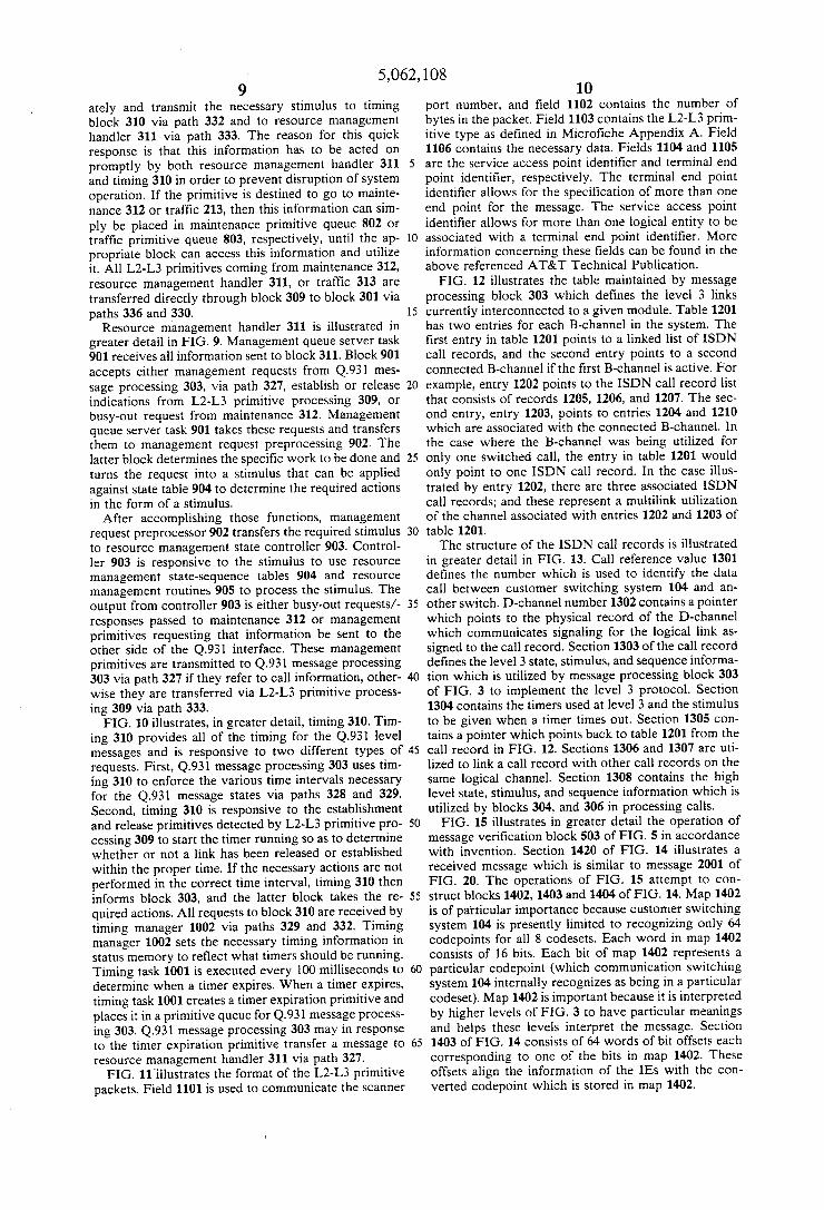
FIG. 12
TABLE \ —_
: B-CHAN ‘ > IsDN \QOZ CALL V1205 \ RECORD 1
1203 ——
RECORD : 1206
' > RBI ' L REOORD ”\ 1207
T2OA ——
> B-CHAN ‘ 4’ ISDN
REélOLFED ?lm ——— x 12 ID
> ISDN OALL
REOORD _\ ‘209
13 DALL REFERENCE VALUE / 1501
D-ORANNEL 1: /150Z
LEvEL 3 STATE, STIMULUS. AND / T503 SEQUENCE INFORMATION
LEvEL 3 TININO INEORNATION / 1504
TABLE T2O T POINTER /15O5
REVERSE POINTER / ‘506
FORNARD POINTER / ‘507
HIGHER LEvEL STATE. STIMULUS, ‘506 AND sEOOENOE INFORMATION
5,062,108

US. Patent > Oct. 29, 1991 Sheet 9 of 15 5,062,108
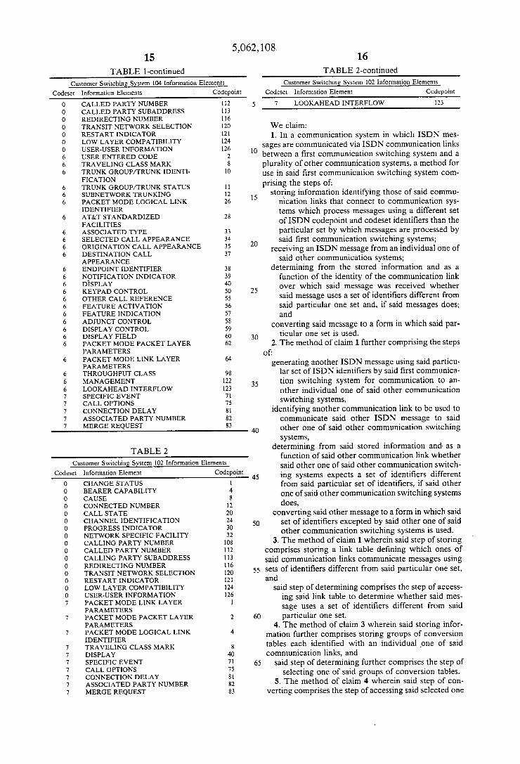
FIG. 14
1401
POINTERS AND AUDIT INFORMATION /
_ T402 4 NORD IE BIT MAP /
/1403 o4 WORDS OF BYTE OEFsETs WITHIN
MESSAGE BUDY FOR EACH IE PRESENT ONE WORD FOR EACH BIT IN THE
4~NORD BIT MAP
1404
OFFSETS FOR UNKNOWN IE5
MEBSOSDAYCE /TAO5 /TAO@ 14D? /14D8 1409 DNCOHNAQENREL gigg CRV PYSPCE PCOOIDNET LEN INFO
WU PCODIDNET LEN INFO PCOOIDNET LEN INFO
T 4 = 1 SLAOIEFKT pCOOIDNET LEN N F O PEOOIDNET L E N W F O
\1413 1420
US. Patent Oct. 29, 1991 Sheet 10 of 15 5,062,108
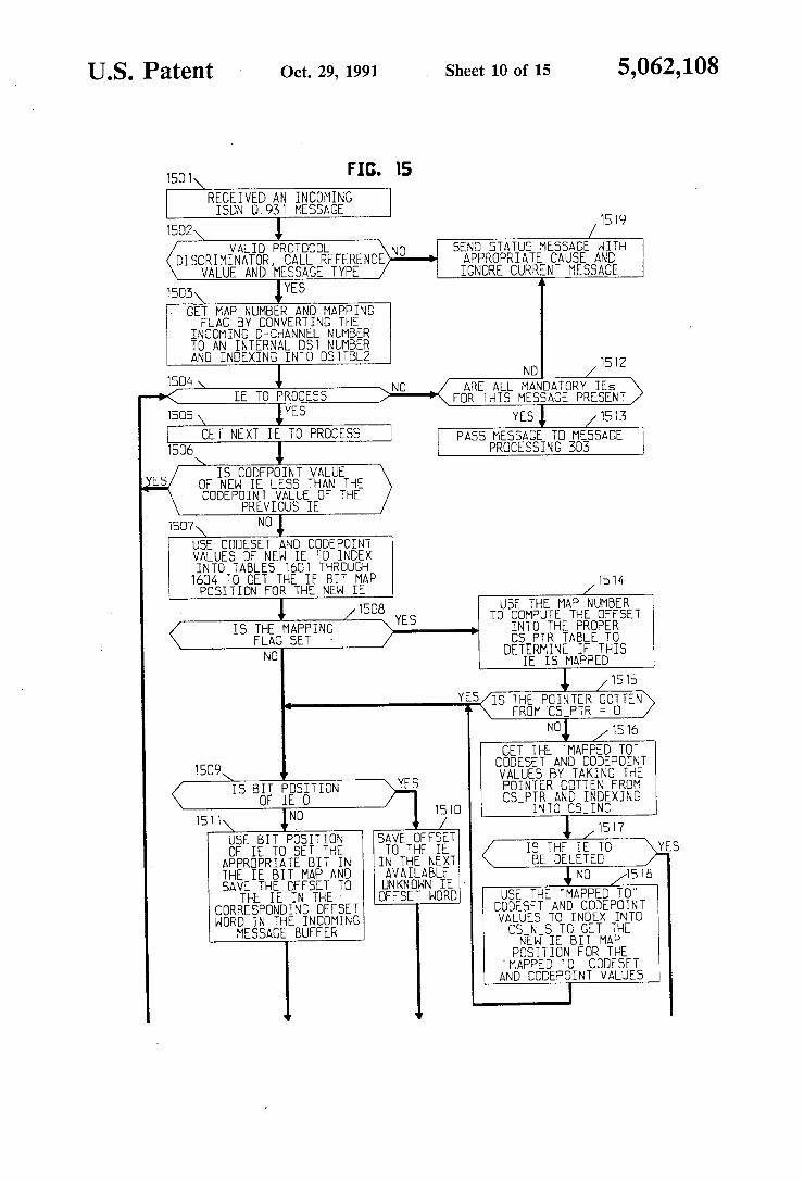
REGEIYEDAN INGDMING ISDN O. 93 T MESSAGE
1502 1 / L519 VALID PROTOCOL NO SEND STATUS MESSAGE WITH
DISCRIMINATOR, CALL REFERENCE APPROPRIATE CAUSE AND VALUE AND MESSAGE TYPE IGNORE CURRENT MESSAGE
I505 ‘YES “ GET MAP NUMBER AND MAPPING
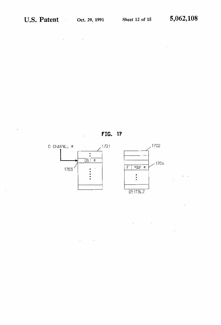
FLAG BY CONVERTING THE INCOMING D-GHANNEL NUMBER TO AN INTERNAL DST NUMBER AND INOEXING INTO OS TTBLZ
ND T512 TSOA
‘ IE TO PROCESS
1505 \ IYES [ GET NEXT IE To PRDGEss J 1506
IS GODEPOINT VALUE OF NEW IE LESS THAN THE CODEPOINT VALUE OF THE
PREVIOUS IE 1507 N0 1
USE COOESET AND CODEPOINT VALUES OE NEN IE TO INDEX INTO TABLES 1601 THROUGH
NO ARE ALL MANDATORY IEs FOR THIS MESSAGE PRESENT
YES 1 1513 PASS MESSAGE TO MESSAGE
PROCESSING 303
1604 To GET THE IE BIT MAP 1514 PGsITIDN FGR IHE NEH IE /
. 1 1505 USE THE MAP NUMBER YES TD GOMPUTE THE GFFsET
IS THE MAPPING 4, INTO THE PRDPER FLAG SET - f Gs PTR TABLE T0 N0 DETERMINE THIS
IE Is MAPPED
1 /T5TB YES 18 THE PGINTER GDTTEN
A FROM CSPTR = D
N0‘, 1516 GET THE "MAPPED TO"
1509 L CUDESET AND GDDEPDINT T VALUES BY TAKING THE
15 BIT POSITION YES PDINTER GDITEN FRDM 0F IE 0 15 D csyIsTéNfDsINggxlNG
T51 l\ 1N0 /‘ - TB I? USE BIT POSITION SAVE OFFSET 0F IE TD SET THE TO THE IE IS THE IE TD YES APPROPRIATE BIT IN IN THE NExT BE DELETED THE IE BIT MAP AND AvAILABLE NO 15 15 SAVE THE OFFSET TD DNKNDNN IE - _ ‘I
THE IE IN THE DFFSET NDRD USE THE MAPPED TD GDRREBPDNDING DFFsET GODESET AND GDDEPDINT HDRD IN THE INGDMING VALUES T0 INDEX INTG
MESSAGE BUFFER Gs_N_s TD GET THE NEH IE BIT MAP
POSITION _FOR THE ' MAPPED TD CODESET AND GDDEPDINT VALUES

US. Patent - Oct. 29, 1991 Sheet 11 of 15 5,062,108
FIG. 16 \ INCDMING CODESET AND CUDEPDM
.______.___J I l_.__‘
CODESET D CODESET 1 CUDESET 2 CODESET 7
160T 1602 1603 1604
BIT POSITION BIT POSITION BIT POSITION
l "vi W 16]] INCONINC MAPPING FUNCTION INC Om
INC OUT ' ' CODESET AND
CODEPOINT
NAPPED CODEPO IN T
OR AND
NOTHING CODESET
I614 16> ——
1b 12 Cum 1E DELETED ' ' 1608
BIT cs_~_s PUS1_TION 1605 \ DNDHZNDED BS-PTR 1616
161D
TIIIIIITIITIIIT
INCOMIND ISDN MESSAGE BUFFER
US. Patent ~ Oct. 29, 1991 Sheet 12 of 15 5,062,108
FIG. I?
D CHANNEL 11 1701
l——> D81 9 1703/
D5 ITBLZ
’ US. Patent - Oct. 29, 1991 Sheet 13 of 15 5,062,108
159 1\ FIG. 16 REGEIvED A REQUEST TO
BUILD A MESSAGE
1802\ 1 GET MAP NUMBER AND MAPPING FLAG BY
GDNvERTING THE DUTGDING D-CHANNEL NUMBER TD AN INTERNAL DST NUMBER AND 1823 INDEXING INTo DS ITBLZ
DUEUE MESSAGE ‘805 1 GREATED FOR SGAN 4-NORD BIT MAP TD LZ-LS MESSAGE
GET AN IE TD BUILD I/D 301 NO
MAPPING FLAG SET / 1618
SCAN EXPANDED IE BIT MAP 1817 t (ES_MP_IE) TD GET AND IE
TD BUILD
USE IE BIT PDSITIDN AS AN INDEX INTO IE_AD_TB
GET THE IE RDUTINE ADDRESS TO BUILD THE IE
1807 \ 1 GDTD IE RDUTINE AND
UILD THE
IEJUB \ "
GET IE GDDEPDINT vALUE BY USING BIT PDSITIDN GDTD IE RDUTINE AND AS INDEX INTD IS_BITDP BUILE THE IE
TABLE
TBD9 1 USE THE MAP NUN TO COMPUTE THE OFFSET
1814
GET THE "MAPPED TO' CODESET AND CODEF‘OINT VALUES BY TAKING THE POINTER OOTTEN FROM CS_PTR AND INDEXINC
INTO CS_OUT
USE CURRENT CODESET T6 15 YES
ATNOD SEEUTDEAPUBIINTT IVNALTULETES IS THE IE TO BE DELETED
USE "MAPPED TO' CODESET 1 AND CODEPOINT VALUES TO
SET A BIT IN THE EXPANDED IE BIT MAPJ (CS_MP_IE)

US. Patent - Oct.29, 1991 Sheet 14 of 15 I 5,062,108
NOTHING I
1 MAPPED CODEPGINT l MEEED AND CODESET
DDDESET 1 1
1
FIG. 19
1‘—_ - ' —_'_‘__1ém's? r --------------- "-1 _____________________ __?
1 19 1 1 1 1E BIT MAP 1900 1910 1 1 1E CREATION ROUTINE ADDRESSES 1 1 1 1 1 1: 1E ROUTINE 0 END PASS} 1 1 1 1 ' IE ROUTINE 1 1
1 1 1 IE ROUTINE 2 L 1
1 1111111111111111 1" 1 1 1 1'5 1 ' 1 1 1 1- ---------------- _ --1 1 1
. 1913 1 1 1 I 1* 1E ROUTINE N 1 I E 1 IE_AD_TB 1
' 1 1 1901s 1 1 1912 1 . 1
l 1 |
1 1 ~ 1920 / 1 . 1 1 INC OUT 1
| 1 I. .. 1
1 CODEPOINT 1 1 1 1 1S_BITOP * 1 . 1 , 1901 CODESET 1 1 1
1 . l
1 1 1 1 1 INC OUT 1 1 1
I I. I
' / 1 1 1 1 1915 ' 1 1 . 0 1 1
1 . "
1 1 1 CS_N_S 1 l 1 1 1905
. 1919 1 1 1 1 . 19 111
| l I 1
1 F 1916 1 1 CS-PTR " " ‘ ' —E_>W1DED'_1E€1_1_MT‘150—4 ' '_1 I ‘902 CODESET D
1 l
l 1
1 l
2 3
50021181“ 1 \ CDDE5ET4 1 EODESU 1 CDDESET ‘5 -
1 CODESET e, 1 E? 1917 1 CUDESET 7 ‘
’ 1111111111111111 1 CS_OUT 1 15 1
1_____ _ _E .__1?PZ _ _-_._.__ - _1_ - __ __ -_- _- __-__ __ _ _J
US. Patent - Oct. 29, 1991 Sheet 15 of 15 5,062,108
FIG. 20
MSG LEN NSC LEN
PROT DISC PROT DISC
CRV CRY
MSG TYPE MSG TYPE (SETUP) (SETUP)
CODE POINT CODE POINT (A) (4)
LEN LEN
(BEARER (DEARER CAPABILITY) CAPABILITY] CODE POINT CODE POINT
(24) (24)
FIELD LEN LEN FIELD 20 TO \ (CHAN E x 2020
1 lgf (CHANNEL NT) CODE POINT CODE POINT
( 108) ( (OS)
LEN LEN
(CALLED (CALLED F21OE1L2D PARTY *1) PARTY 14> \ LOCK SHIFT LOCK SHIFT
(7) (6) CODE POINT CODE POINT
(4U) [40) FIELD
FZIUEILIU LEN LEN 202 1 \ (DISPLAY (DISPLAY /
NANE) NANE) CODE POINT LOCK
(82) SHIFT
LEN CODE SET (7)
ASSOC. PARTY CODE POINT NUMBER ((32)
LEN
ISBN ASSOC. PARTY MESSACE NUMBER 2001
ISDN NESSACE
1
ISDN CODESET CONVERSION
REFERENCE MICROFICHE APPENDICES
This application contains micro?che appendices, des ignated A, B, and C, which de?ne functions performed with respect to ISDN messages. The total number of micro?che is 4 sheets and the total number of frames is 238.
TECHNICAL FIELD
This invention relates to communication of ISDN information and, in particular, to the handling of ISDN information elements.
BACKGROUND OF THE INVENTION
ISDN standard Q.93l is intended to provide an inter‘ national standard to control the flow of data and signal ing information between telecommunication switching systems, packet switching systems, and terminals. That standard is an effort to establish an international set of ISDN messages with each message having a number of information elements. The message format is to group information elements by codesets and to identify each information element by a codepoint. The codeset is a term that refers to a group of 133 information element identi?ers. In the ISDN message structure, there are eight possible codesets, numbered 0 through 7. Codeset 0 is the current set of information elements de?ned by ISDN standard Q.93l. Codesets 1 through 4 are re served for future ISDN standard Q.93l expansion. Simi larly, Codeset 5 is for National use; codeset 6 is for information elements speci?c to the local serving net work; and codeset 7 is for user-speci?c information elements. Information elements represent submessages within the ISDN message. The code point is an numeric value assigned to an information element. That numeric value allows identi?cation of the information element. Although ISDN standard Q.93l exists as a standard,
it is not followed with complete compliance for the following reasons. First, from country to country, dif ferences are found in the type of information assigned to each codeset as well as the meaning of an individual codepoint within in a given codeset due to National government regulations. Because of those differences, the usefulness of ISDN Q.93l is limited for international calls. Second, within a given country (e.g. the United States), the lack of national regulations has resulted in individual corporations creating their own standards for various codesets and codepoints. As a result, within a particular country, systems and terminals manufactured by different manufacturers may not be able to communi cate with each other using all of the available codesets. Finally, there may be incompatibilities within one man ufacturer’s product line due to the manufacturer at tempting to align his products with an evolving ISDN Q.93l standard. For example, certain corporate stan dards originally placed certain user-speci?c and local serving network information elements in codeset 7. Later, these elements were rede?ned as part of codeset 6 by changes to ISDN Q.93l. This evolution resulted in older members of a product line being incompatible with newer members of the same product line.
Since incompatibility can exist in the codesets and codepoints, a system or terminal may receive a message which contains an unknown information element. The ISDN Q.93l standard suggest two methods for han dling an unknown information element. The ?rst
15
4-0
45
55
60
65
5,062,108 2
method is to ignore the unknown information element completely, and the second method is to drop the call for which the unknown information element was re ceived. The problem with these two methods is that no provision is made for incompatibilities in implementa tions of the ISDN Q.93l standard at the national, manu facturer, or intra-manufacturer level. What is needed is a procedure that will resolve incompatibilities at those levels.
SUMMARY OF THE INVENTION
In a telecommunication switching system, a technical advancement is achieved by an apparatus and method for automatically converting ISDN codeset and code point protocol in messages transmitted to the telecom munication switching system from a plurality‘ of other telecommunication switching systems, each using a different ISDN codeset and codepoint protocol than the protocol used by the telecommunication switching system that identi?es the same data information. All telecommunication switching systems are intercon nected by data channels. In response to an ISDN mes sage from one of the plurality of other telecommunica tion switching systems, the apparatus identi?es the data channel communicating the message, indexes into a channel table using the identity of the data channel to determine the need to convert the codeset and code point protocol, and if needed, converts the codeset and codepoint protocol to that of the receiving telecommu nication switching system.
Further, the apparatus is responsive to an ISDN mes sage generated by the telecommunication switching system for transmission to another one of the plurality of telecommunication switching systems to identify the data channel that is to communicate the ISDN message, to index into the channel table to determine the need to convert, and if needed, to convert the codeset and code point protocol of the message to the codepoint and codeset protocol of the other one of the plurality of telecommunication switching systems. In addition, there are sets of conversion tables, each set identi?ed with an ISDN data channel. The identity of the data channel is used to select which set of tables is to be used to convert the codeset and codepoint protocol. For each set of codepoint and codeset identi?ers in the ISDN message, the apparatus ?rst accesses one of the selected set of tables to determine if conversion is needed and accesses the remaining tables of the selected set to perform the conversion.
BRIEF DESCRIPTION OF THE DRAWING
FIG. 1 illustrates, in block diagram form, a system embodying the inventive concept; FIG. 2 illustrates a business communication system
for practicing the invention; FIG. 3 illustrates the ISDN software structure used
to control the system of FIG. 2; FIG. 4 illustrates, in block diagram form, L2-L3 mes
sage I/O 301 of FIG. 3; FIG. 5 illustrates, in block diagram form, Q.93l mes
sage handling 302 of FIG. 3; FIG. 6 illustrates, in’ block diagram form, message
. processing 303 of FIG. 3; FIG. 7 illustrates, in block diagram form, call handler
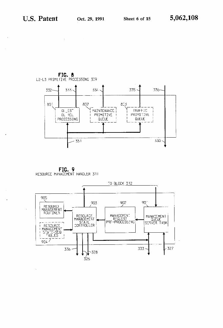
304 of FIG. 3; FIG. 8 illustrates, in block diagram form, L2-L3
primitive processing 309 of FIG. 3;

5,062,108 3
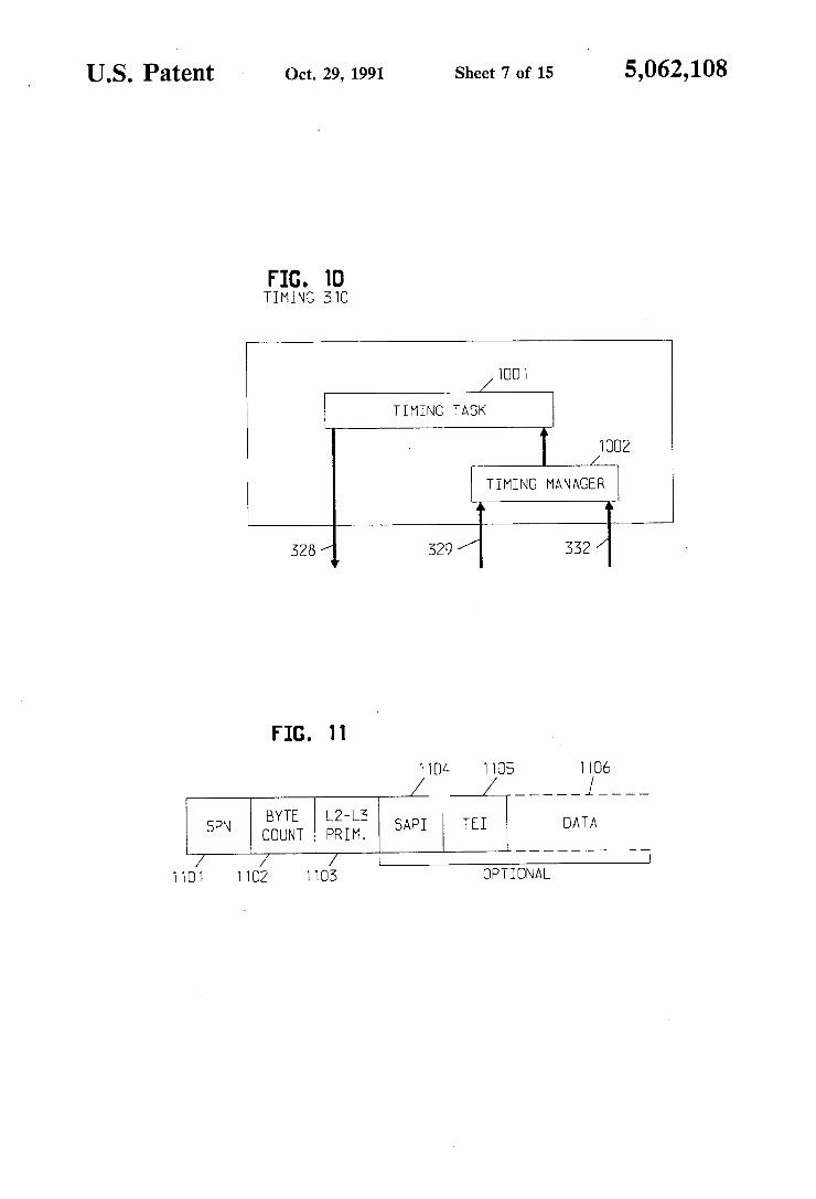
FIG. 9 illustrates, in block diagram form, resource management 311 of FIG. 3; FIG. 10 illustrates, in block diagram form, timing 310
of FIG. 3; ' FIG. 11 illustrates the format of L2-L3 primitive
packets; FIG. 12 illustrates, in block diagram form, linked
ISDN call records; FIG. 13 illustrates the layout of a ISDN call record; FIG. 14 illustrates the format of a level 3 ISDN mes
sage; FIG. 15 illustrates, in ?ow chart form, message veri?
cation operations; FIG. 16 illustrates tables used by the message veri?
cation operations; FIG. 17 illustrates tables for identifying conversion
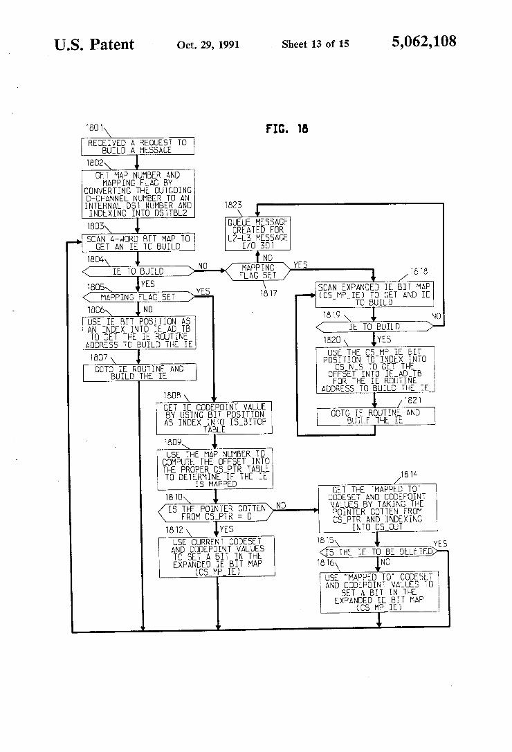
mapping on the basis of a D-channel number; FIG. 18 illustrates, in flow chart form, message cre
ation operations; FIG. 19 illustrates tables used by the message cre
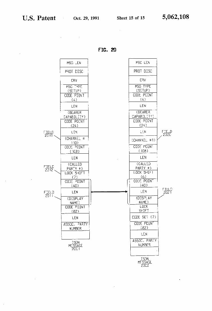
ation operations; and FIG. 20 illustrates the conversion of an incoming
ISDN message to an outgoing ISDN message.
DETAILED DESCRIPTION
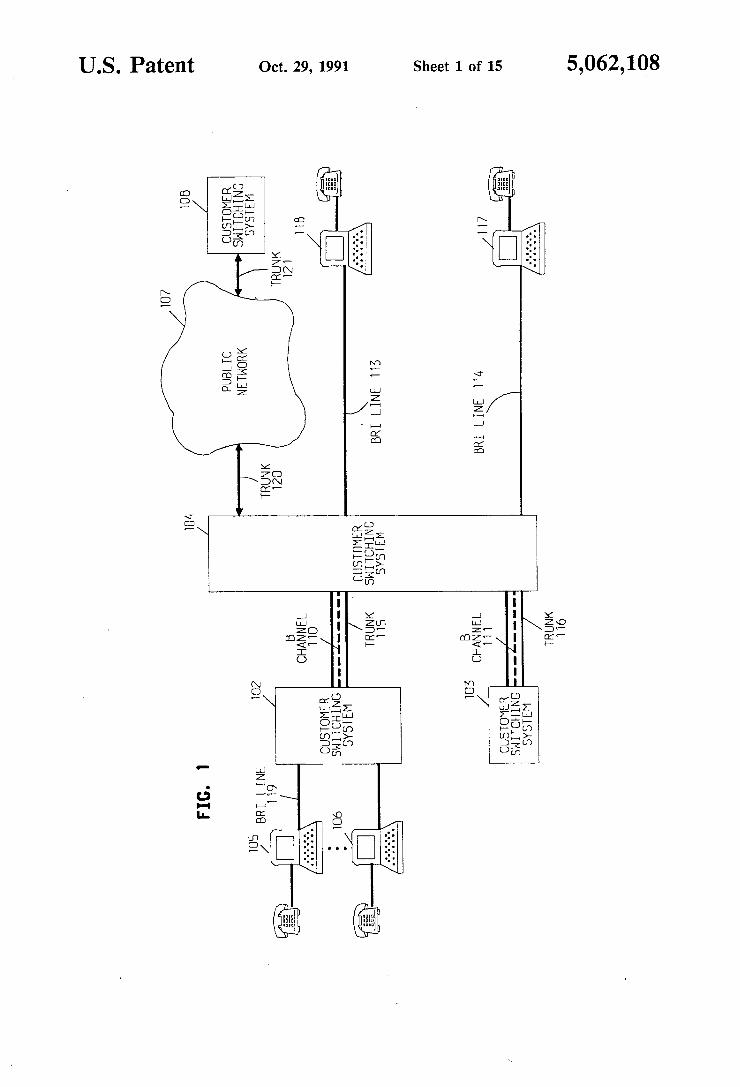
In FIG. 1, customer switching systems 102, 103, and 104 are physically interconnected by ISDN primary rate interface (PR1) trunks (also referred to as commu nication links) each having advantageously 23 bearer channels (B channels) and l control channel (D-chan nel). Customer switching systems are also referred to as PBXs or PABXs. Each channel has a transmission ca pacity of 64 Kbs. Terminals 105, 106, 117, and 118 are physically interconnected to the switches by ISDN basic rate interface (BRI) lines, each having two 64 Kbs channels and a 16 Kbs control channel.
Consider the following illustrative example which is in accordance with the invention. During the origina tion of the call, customer switching system 104 estab lishs an ISDN connection between BRI terminal 118 and BRI terminal 105 via BRI line 113, channel 110 of trunk 115, customer switching system 102, and BRI line 119 using a call setup message. Customer switching system 104 is a different vintage PBX than customer switching system 102 and uses a different set of codeset and codepoint identi?ers (also referred to as codeset and codepoint protocol) which is de?ned in Table l. The set of codeset and codepoint identi?ers for cus tomer switching system 102 is given in Table 2. (Tables 1 and ,2 are at the end of Detailed Description section.) As part of call origination, customer switching system 102 transmits to customer switching system 104, via the D channel of trunk 115, ISDN message 2001 of FIG. 20. Message 2001 includes the channel number IE (codeset 0, codepoint 24) de?ning that B channel 110 (?eld 2010) is to be the communication path and the display IE (codeset 7, codepoint 40) containing the alphanumeric name of the person (?eld 2011) assigned to originating BRI terminal 105. As illustrated in FIG. 20, customer switching system 102 transmits the display IE in codeset 7 as codepoint 40 (?eld 2011), but customer switching system 104 expects that the display IE will arrive in codeset 6 as codepoint 40 (?eld 2020) as illustrated by ISDN message 2002. Lock shift ?eld 2012 de?nes that the codeset has changed from codeset 0 to codeset 7. Upon receipt of message 2001, customer switching
system 104 recognizes that the message arrived from trunk 115. System administration had previously
15
20
25
35
45
55
65
4 marked trunk 115 as requiring message conversion, and customer switching system 104 converts the codepoint 40 in codeset 7 to codepoint 40 in codeset 6. Customer switching system 104 forms an internal message similar to message 2002. Initially, customer switching system 104 forms this message so as to properly verify message 2001 since the internal software structure assumes that every received message is of the set of identi?ers de ?ned in Table 1. Since BRI terminal 118 utilizes the same standard as customer switching system 102, cus tomer switching system 104 converts the codepoint and codeset back to the origial values before transmitting the message on BRI line 113 to BRI terminal 118. The message transmitted to BRI terminal 118 is similar to message 2001 except that the ?eld corresponding to ?eld 2010 defines a B channel on BRI line 113. If the message was transmitted to BRI terminal 117 which utilizes the same set of identi?ers as customer switching system 104, there would be no need to convert the set of identi?ers. Customer switching system 104 would trans mit a message similar to message 2002 to BRI terminal 117 except the channel number ?eld would identify a B channel in BRI line 114. As explained in greater detail with respect to FIGS. 15 through 19, customer switch ing system 104 utilizes internal tables which are admin istered by a system administrator to determine which trunks or BRI lines must be converted and what that conversion should be. As illustrated in FIG. 1, customer switching system
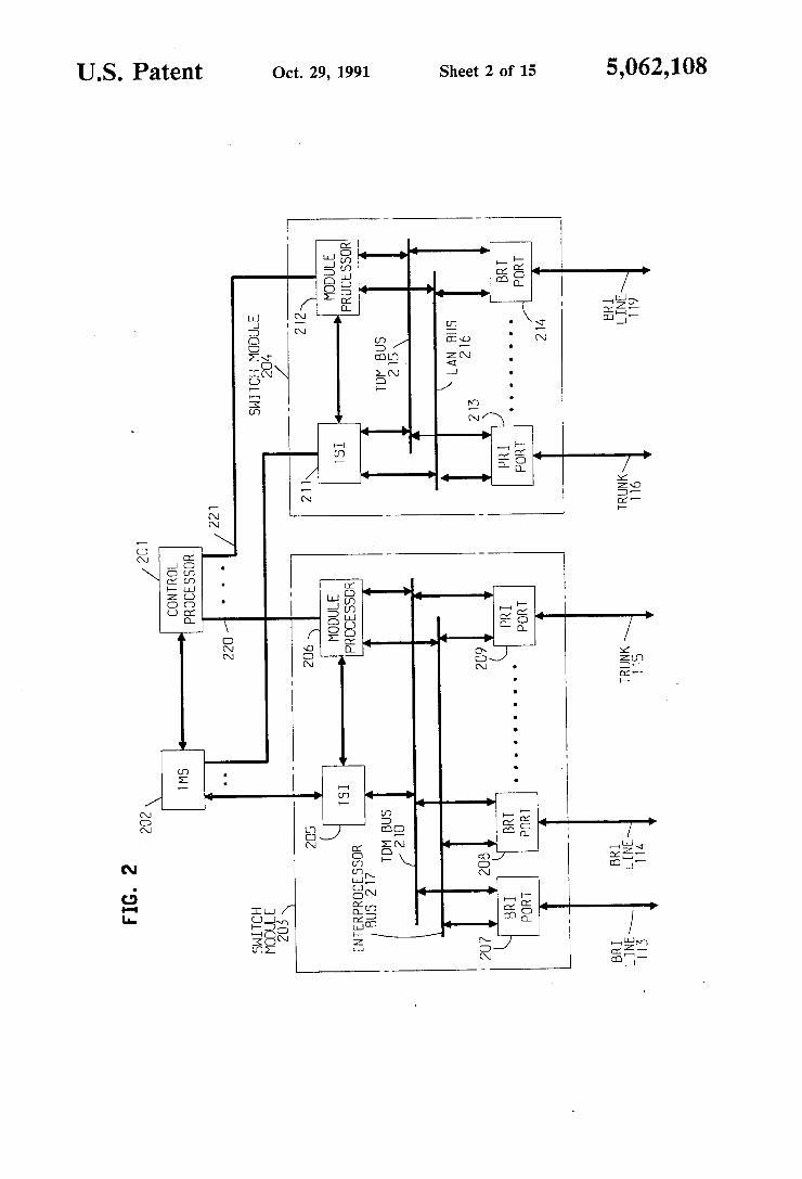
104 is connected to public network 107 via trunk 120. Public network 107 could be a continental network or an international network in which case customer switching system 108 would be in a foreign country and operate on a different version of the ISDN standard. Customer switching system 104 could serve as a gate way for customer switching systems 102 and 103 as well as BRI terminals 118 and 117 by translating the standard implemented by customer switching system 108 to a standard recognizable by the equipment interconnected to customer switching system 104. In addition, cus tomer switching system 104 is capable of converting any of the codepoints and codesets as deemed necessary by the system administrator of customer switching sys tem 104 and is not limited to present display IE exam ple. Customer switching system 104 is illustrated in
greater detail in FIG. 2. Customer switching system 104 comprises switch modules 203 and 204, time matrix switch (TMS) 202 and control processor 201. Each switch module is illustrated as terminating a plurality of ISDN PRI trunks or BRI lines. Each switch module routes all intra-module calls within itself; whereas, in ter-module calls must be routed through TMS 202. The data received from the PRI trunks within switch
module 203 is interconnected via time division multi plex (TDM) bus 210 with each channel being assigned a time slot for receiving data and a time slot for transmit ting data on bus 210 and all time slots are switched through time slot interchange (TSI) 205. The functions performed by TDM 210, T5] 205 and TMS 202 are well-known in the art.
Switch module 204 functions in a different manner than switch module 203. Channels communicated within switch module 204 do not have to be switched through TSI 211 but can be switched directly on TDM bus 215. TSI 211 is only used for inter-module calls. The ISDN messages are transmitted ‘via the PRI
trunks in a D-channel which is the 24th channel of each
5 trunk. Within switch module 203, the messages associ ated with logical channel 110 are received via the 24th channel of trunk 115 and are terminated at ISDN level 2 by PRI port 209. Interlevel communication messages designated as L2-L3 primitive are then transferred via interprocessor bus 217 to module processor 206. ISDN messages associated with logical channel 111 are com municated in the 24th channel of trunk 116. These mes sages are transferred via LAN bus 216 to module pro cessor 212. LAN bus 216 is not used for packet switch ing. The latter processor terminates level 2 before trans ferring the L2-L3 primitive messages via datalink 221 to control processor 210. Customer switching system 104 can also terminate a
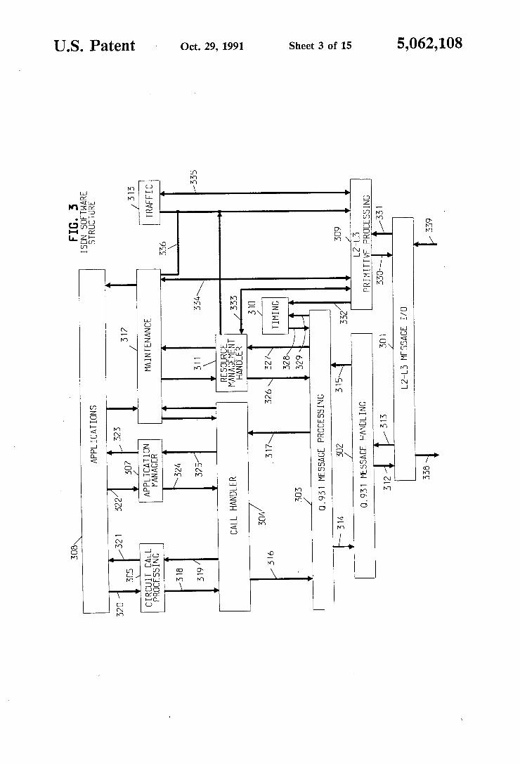
variety of standard analog telephones and trunks and also digital telephones and terminals utilizing the AT&T DCP protocol. Such telephones and terminals are not illustrated in FIG. 2. FIG. 3 illustrates the ISDN software structure that is
implemented by control processor 201. The non-ISDN functions performed by control processor 210 and low level functions performed by the module processors are not shown; however, circuit call processing block 305 and maintenance block 312, which are executed by control processor 201, include the call processing and maintenance for the non-ISDN functions. In general, blocks 304 through 306 are concerned with the manage ment of voice and data calls whereas blocks 309‘ through 313 are concerned with the maintenance and resource management tasks. Blocks 307 and 308 are utilized by high level applications. The software archi tecture of FIG. 3 receives messages which are transmit ted from level two via input and output paths 338 and 339. The format of these messages is illustrated in FIG. 11, and further details on level two and level three messages may be found in AT&T Technical Publication Number 41449 and Addendum 41459. L2-L3 message I/O block 301 receives information from path 311. The primitives on paths 338 and 339 are de?ned by ?eld 1103 of FIG. 11. Micro?che Appendix A gives further details on these primitives. Block 301 is responsible for handling all L2-.L3 information to and from a module. After handling these messages, block 301 transfers all of the received L2-L3 primitives that indicate a Q93] message, which is the DL_DATA_INDICATION, to Q.93l message handling block 302 for processing. All other L2-L3 primitives received by block 301 are trans ferred to block 309 for processing.
Q.93l message handling block 302 is responsible for verifying and creating all Q.93l messages. Block 302 interfaces with L2-L3 message I/O 301 by receiving and sending all of the DL_DATA_INDICATION primitives which contain incoming or outgoing Q.93l messages. Q.93l message handling communicates with Q.93l message processing 303 by passing either a veri ?ed Q.93l message or receiving a request to build a Q.93l message.
Q.931 message processing 303 provides the control of the Q.931 operation and does this by maintaining state tables which de?ne the state of the Q.93l message pro tocol for each Q.93l channel which has been established or is being established within any module of system 200 of FIG. 2. Q.93l message processing 303 negotiates the establishment of Q.93l channels, supervises their activ ity and eventually releases them. Block 303 communi cates with call handler 304, resource management han dler 311, and timing block 310.
40
55
65
5,062,108 6
Call handler 304 is utilized to provide an interface for the Q93] message being communicated between block 303 and circuit call processing 305, multilink 306, appli cation manager 307, and maintenance 312. Circuit call processing 305 is responsive to analog telephone and trunk like stimulus to provide the overall call processing functions. Call handler 304 is responsive to the Q.93l message processing 303 to convert the Q.93l messages into analog telephone and trunk like stimulus to be passed to circuit call processing block 305. Timing block 310 provides all the necessary software
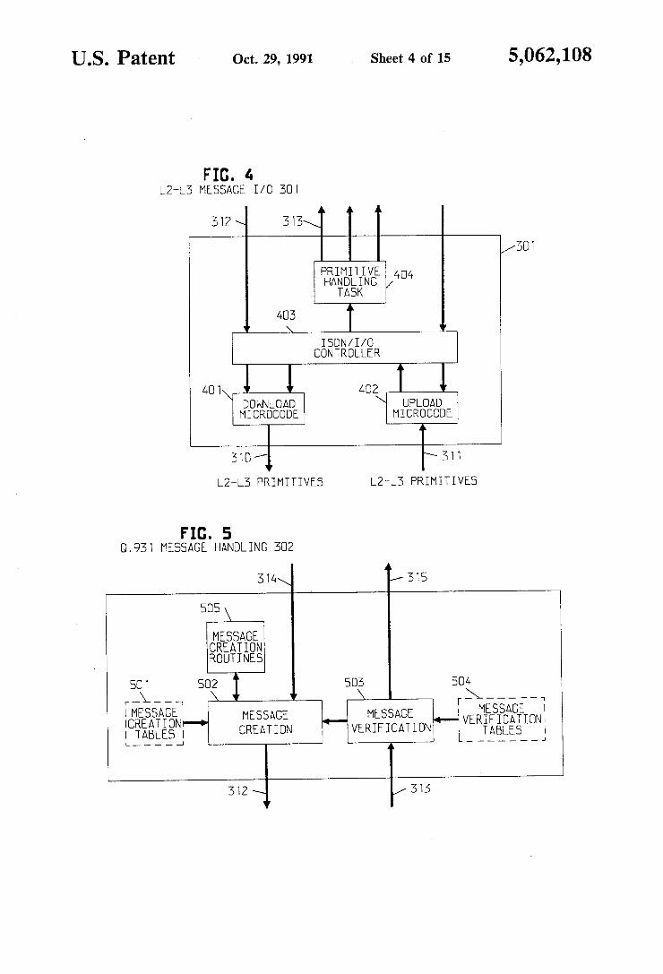
timers for block 303. Resource management handler 311 is responsible for controlling the service status of cir cuits and the link status of level two. Maintenance 312 performs the normal maintenance type tasks for the ISDN portion of system 104. Traf?c block 313 per forms the standard traf?c measurement type functions. L2-L3 message I/O block 301 is illustrated in greater
detail in FIG. 4. ISDN I/O controller block 403 is a task which runs every ten milliseconds on control processor 201 and is responsible for moving all of the ISDN infor mation in and out of control processor 201. Controller 403 functions by calling microcode routines 401 and 402 to move information into and out of a queue of input message buffers and a queue of output message buffers, respectively. The input into controller 403 is an L2-L3 primitive, DL_DATA_REQUEST primitive, re ceived from message handling block 302 via path 312. This primitive is passed to controller 403 along with a message buffer. All messages received from level two by block 301 are passed from controller 403 to primitive handling task 404. Primitive handling task 404 is also run every ten milliseconds and is used to process all of the L2-L3 primitives. Primitive handling task 404 han dles these primitives in one of two ways. Either control is passed to a routine speci?ed for that primitive in blocks 302 or 309 which is done for primitives requiring immediate attention or the primitive and information related to the primitive are stored in a speci?c queue for that primitive for later execution. Subsequently, the queue is passed to block 309. The storing of the primi tive and related information is done for tasks which may be performed at a later time. Such tasks include mainte nance and traf?c type operations. When primitive han dling task 404 directly passes control to a routine, for example in message handling block 302 to process a primitive, it is passing control of control processor 201 and that control is returned by the receiving routine to primitive handling task 404 once the routine has ?n ished executing. Turning now to FIG. 5, it will be recalled that Q.93l
message handling block 302 is responsible for verifying and creating all Q.93l messages. Block 302 interfaces with message I/O block 301 via paths 312 and 313 by receiving DL_DATA_INDICATION and sending DL_DATA_REQUEST primitives containing an incoming or outgoing Q.93l message, respectively. Block 302 communicates with Q.93l message process ing block 303 via paths 314 and 315 by passing either a veri?ed Q.93l message or receiving a request to build a Q.93l message. Message veri?cation block 503 receives control from message I/O block 301 when a Q.931 message has been received and needs to be veri?ed. Block 503 parses the message and checks for any mes sage format error and veri?es that all the mandatory information is included based on the speci?cations as published in the aforementioned AT&T Technical Pub lication. All of the information needed to check the

5,062,108 7
received message is contained in message veri?cation tables 504. The message is parsed by storing pointers into the buffer containing the message that point to the different types of information in the message. In particu lar, block 503, using information from tables 504, per forms the codeset and codepoint conversion for incom ing messages which is the subject of this invention. ‘Further details with respect to that conversion are given in the discussion of FIGS. 15 through 19. Mes sages that are successfully parsed are passed to message processing block 303 via path 315. Message veri?cation block 503 is responsive to two different types of errors in received messages. Certain types of errors are simply logged in a general area utilized to log errors which will be processed later if necessary. Such errors would re sult, for example, if a message came that was simply incomplete. The other type of message error is where the message is complete but speci?es a logical entity that did not exist, for example, referring to a call that does not exist. Such an error requires an immediate response, and message veri?cation block 503 transmits a request to message creation block 502 to transmit a message to the sender of the message in error giving the status of the received message and a code specifying what the error was. Message creation block 502 receives requests to build
a message from either message veri?cation block 503 or Q.93l message processing block 303. Block 502 pro vides the control for properly creating a message. All of the information elements included in a message are created by individual routines contained in message creation routines block 505. In particular, blocks 502 and 505, using information from tables 501, perform the codeset and codepoint conversion for outgoing mes sages which is the subject of this invention. Further details with respect to that conversion are given in the discussion of FIGS. 14 through 19. Information for building each type of message is contained in message creation tables 501. Message creation block 502 builds a requested message by generating the proper message information using the routines in message creation rou tines block 505. Each of these routines is invoked by block 502 for a speci?c information element (IE), and each IE routine contains all of the information on whether an IE should be created for a given situation and all of the rules on what information goes in the IE.
Q.93l message processing block 303 is illustrated in greater detail in FIG. 6. Block 303 is responsible for allowing system 104 to communicate with other data equipment at the peer level of Q.93l and is responsible for such functions as establishing peer type communica tion at Q.93l, maintaining this communication, and releasing such communication when necessary. Mes sage processing block 303 also maintains a set of tables which de?ne the status, call type, and used facility for all level 3 links for both circuit and data calls. The processing performed by block 303 is classi?ed
as maintenance processing, trunk-side processing, or line-side processing. The trunk-side and line-side pro cessing are used to map call stimulus received in Q.93l messages into the call control message which can be used by circuit call processing block 305. The mainte nance processing is used to handle all messages that apply to the “null“ or “global" call reference values for both lines and trunks. A “null” reference value indicates that the message is not associated with any call. Whereas; a “global“ reference value indicates it is asso
25
40
45
60
65
8 ciated with all calls on the receiving BRI or PRI inter face. Message queue server task 605 is a task which is run
every ten milliseconds on each module processor and checks to see if there is any work for block 303 in the form of incoming messages from blocks 304, 311, or 310. The incoming messages are left in message queues by the latter blocks. In addition, it looks for messages coming from Q.93l message handling block 302. Queue server task 605 is responsive to those messages to inter pret the work to be done and to convert that work into state-stimulus information and to determine the state table and speci?c call record to which the work applies. After doing that, message queue server task 605 then activates message state sequence controller 604 to pro cess the state and stimulus information using routines 606, 607, and 608 with the state-sequence information coming from tables 601, 602, and 603. The processed information is transferred to blocks 302, 304, 310, or 311 in message queues. Micro?che Appendix B, section 8 de?nes, in greater detail, the functions performed by maintenance processing routines 606 and maintenance state-sequence tables 601. Section 5 of micro?che Ap pendix B de?nes, in greater detail, the functions per formed by trunk-side processing routines 607 and trunk side state-sequence tables 602. Micro?che Appendix C de?nes, in greater detail, the functions of line-side pro cessing routines 608 and line-side state-sequence tables 603.
Call handler 304 is illustrated in greater detail in FIG. 7. Call handler queue server task 701 interrogates one of two queues for work. One queue is for messages from the Q.93l layer which are received from block 303, and the second queue is for higher layers which are blocks 305, 306, 307, and 312. If work is found in either of these queues, block 701 transfers the information along with the stimulus to call handler state controller 702. Con troller 702 classi?es the stimulus and information as being a maintenance or call type. Controller 702 sends the maintenance type which are restart requests and responses to maintenance block 312 for processing.
Calls are divided into four categories trunk, line, multilink, and non-switched. Calls are identi?ed as being in one of these categories based on the contents of the call record tables maintained by message processing block 303. If a call is the only call associated with a channel, it is assumed to be an ordinary telephone call or standard circuit switched call. If a call is one of plu rality of calls on a channel, it is assumed to be a mul tilink call. If a call is not assigned to a channel, it is assumed to be a non-switched call. Controller 702 pro cesses each of these by using a separate set of state tables.
Standard circuit switched calls are processed to map the stimulus into the analog telephone and trunk format used by circuit call processing block 305, and that pro cessed stimulus is then transferred to block 305. The multilink stimulus is processed and transferred to mul tilink block 306. The non-switched stimulus is processed and transferred to application manager 307 via path 325.
Circuit call processing block 305 is a well known circuit switched call processing as performed by cus tomer communication switching systems. An example of such a system is the AT&T System 85. L2-L3 primitive processing block 309 is illustrated in
greater detail in FIG. 8. Ifthe information concerns the establishment or the release of a link, then block 301 causes routine 801 to process this information immedi


![Cis TelePresenCo Ce isDn link...ISDN PRI Interface 1 testShutdown ISDN BRI Interface [1..4] testLoopmode ISDN BRI Interface [1..4] testPattern Cisco telePresence ISDN Link Administrator](https://img.dokumen.tips/doc/110x75/6131c5191ecc51586944f1c2/cis-telepresenco-ce-isdn-link-isdn-pri-interface-1-testshutdown-isdn-bri-interface.jpg)