Embed Size (px)
Citation preview

I. Basic Lower Extremity Anatomy
Ischial Containment Prosthetics

Introduction
The following is a brief overview of lower extremity anatomy to be used in transfemoral prosthetics. It will help you identify the anatomical structures that will be critical to the accurate evaluation of the patient and fabrication of an transfemoral prosthesis. A good understanding of this anatomy is necessary to produce a well-fitting prosthesis.
You should refer to an anatomical source for more complete information. Students with English reading skills can link directly to Gray’s Anatomy online.

Anatomical position
To communicate accurately about body position, it is necessary to use a standard reference position. That standard is the anatomical position.
In anatomical position, the person is standing with an erect posture, facing forward, with arms at the sides, palms of the hands facing forward, and fingers and thumbs extended. Anatomical position

Anatomical position
Anatomical position is the standard reference position for definitions and descriptions of body planes and directions. It is also the designated “zero position” from which joint motions for most of the joints of the body are measured.
90ª
Measuring joint motion

Planes of the body
There are three basic planes of reference in the body: the sagittal plane, the coronal plane and the transverse plane. All of these planes are at right angles to one another.
Transverse
Frontal
SagittalPlanes of the body

Planes of the body: Sagittal plane
The sagittal plane is a vertical plane that divides the body into the left and right halves. It may also be referred to as the anterior posterior plane. Evaluation,of movement is best viewed from the side of the person’s body.
Note that the sagittal plane that divides the body into two equal halves is known as the midsagittal plane.
Sagittal plane

Planes of the body: Coronal plane
The coronal plane is a vertical plane that divides the body into front and back (or anterior and posterior) portions. It may also be referred to as the frontal plane. Evaluation of movement on the coronal plane is best viewed by standing in front of or behind the person’s body.
Coronal plane

Planes of the body: Transverse plane
The transverse plane is a horizontal plane that divides the body into upper and lower (or proximal and distal) portions.
Transverse plane

Center of mass
The center of mass is the balancing point of the body. In a sound individual with ideal posture, it is approximately located just anterior to the second sacral vertebra.
Center of mass

Terms of direction
Terms of direction will be used when describing locations on the body. Because they are defined relative to the standard anatomical position, these terms are accurate regardless of the body position. For example, the directions “up” and “down” change depending on whether the person is lying or standing, but the terms of direction remain constant.

Terms of direction: Proximal
Proximal means situated close to or nearest the point of attachment or origin. It refers to the placement on an extremity compared to its point of attachment relative to the body. For example, the ischial tuberosity is located proximal to the knee.
Knee
Ischial Tuberosity
Anterior view

Terms of direction: Distal
Distal means farther away from the attachment point or point of origin. It refers to the placement on an extremity compared to its point of attachment relative to the body. For example, the adductor tubercle is distal to to the ischial tuberosity.
Adductor Tubercle
Posterior view
Ischial Tuberosity

Terms of direction: Anterior
Anterior means toward the front of the body in the sagittal plane. For example, the patella is located on the anterior aspect of the leg.
Anterior view
Patella

Terms of direction: Posterior
Posterior means toward the back of the body in the sagittal plane. For example, the hamstrings are located on the posterior aspect of the leg.
Posterior view

Terms of direction: Medial
Medial means toward the midline of the person in the coronal plane. For example, the adductor tubercle is on the medial side of the femur.
Adductor tubercle
Anterior view
Femur

Terms of direction: Lateral
Lateral means away from the midline of the person in the coronal plane. For example, the greater trochanter is on the lateral side of the femur.
Greater trochanter
Anterior view
Femur

Axes of the body
The axes of the body are imaginary reference lines of the body, about which movement takes place and from which it is defined.

Axes of the body: Coronal axis
A coronal axis is a line that is found in the coronal plane and extends from side to side. The movements of flexion and extension occur about this axis in the sagittal plane.
Movements about the coronal axis

Axes of the body: Sagittal axis
A sagittal axis is a line that is found in the sagittal plane and extends from anterior to posterior. The movements of abduction and adduction occur about this axis in the coronal plane.
Movements about the sagittal axis

Axes of the body: Longitudinal axis
A longitudinal axis is a vertical line extending in a proximal–distal (or cranial–caudal) direction. The movements of medial and lateral rotation occur about this axis in the transverse plane.
Movements about the longitudinal axis

Ankle Motions: Plantarflexion
Plantarflexion is the ankle motion involved in pointing the toes. In plantarflexion, the ankle bends to move the bottom of the foot, or plantar surface, posteriorly. A normal amount of plantarflexion is approximately 45 degrees.
45º of Plantarflexion

Ankle Motions: Dorsiflexion
Dorsiflexion is the ankle motion involved in raising the foot. In dorsiflexion, the ankle bends to bring the top of the foot, or dorsal surface, toward the face. A normal amount of dorsiflexion is 15-20 degrees. 15º - 20º of Dorsiflexion

Hip motions: Flexion
Hip flexion is the movement of the femur forward or in the anterior direction. The range of hip flexion is 0- 125º. The knee joint should be flexed when measuring hip joint flexion in order to avoid a lower measurement due to hamstring tightness.
0º to 125º of hip flexion

Hip motions: Abduction
Hip abduction is movement of the femur away from the midpoint of the body in the coronal plane.
Hip abduction

Hip motions: Abduction
Hip adduction is movement of the femur toward the midpoint of the body in the coronal plane.
Hip adduction

Osteology: Knee joint
Femur
Patella
FibulaTibia
Adductor Tubercle
Medial Tibial Plateau
Right knee region, anterior view

Osteology: Femur (anterior aspect)
_________* Not palpable.
Medial EpicondyleLateral Epicondyle
Femoral Shaft*
Head of the Femur*
Femoral Neck*
Lesser Trochanter*
Adductor Tubercle
Right femur, anterior view
Greater Trochanter

Osteology: Femur (posterior aspect)
Lateral Condyle
Head of the Femur*
Lesser Trochanter*
Medial Condyle
Femoral Shaft*
Femoral Neck*
Greater Trochanter
Right femur, posterior view
Linea Aspera*
_________* Not palpable.

Osteology: Pelvis (anterior aspect)
Sacrum
Acetabulum
Pubic SymphysisIschial Tuberosity
Iliac Fossa
Anterior Superior Iliac SpineAnterior Inferior Iliac Spine
Obturator Foramen
Pelvis, anterior view

Osteology: Pelvis (posterior aspect)
The ischial tuberosity is an important landmark. This is a weight-bearing area for the transfemoral amputee as well as being the insertion for the hamstring muscle group.
Ischial Tuberosity
Pelvis, posterior view

Myology of the thigh: Hamstrings
The hamstrings are hip extensors and knee flexors. Their most important role is normally that of decelerating hip flexion late in swing in preparation for placing the foot on the floor. Hamstrings are important for the transfemoral amputee for providing voluntary knee stability through hip extension.
Ischial Tuberosity
Thigh, posterior view
Biceps femoris
Semi- tendinosis
Semi- menbranosis

Myology of the thigh: Quadriceps
The quadriceps muscle is composed of four muscles: the vastus lateralis, vastus medialis, vastus intermedius*, and rectus femoris.
__________* Not shown
Rectus Femoris
Vastus Lateralis
Patella
Vastus Medialis
Sartorius
Thigh, anterior view

Myology of the thigh: Quadriceps
The quadriceps are active in knee extension, and these muscles are normally active in limiting knee flexion when there would be a tendency for the knee to bend (a flexion movement) during weight bearing. The quadriceps compose much of the soft tissue of the anterior thigh.
Insertion of Tibial Tubercle
Origin of Biceps Femoris
Vastus Medialis
Vastus Lateralis
Rectus Femoris
Thigh, anterior view

Myology of the thigh: Quadriceps
The quadriceps muscles insert collectively onto the tibial tubercle of the tibia through a common tendon known as the patellar tendon. This area of insertion is missing on the transfemoral amputee; therefore, the surgeon will perform a myodesis or myoplasty to tie the loose ends of the muscles.
Insertion Tibial Tubercle
Origin Rectus Femoris
Thigh, anterior view
Origin Vastus Intermedius, Medialis and Lateralis

Myology of the hip: Hip abductors
The hip abductors stabilize the pelvis in the coronal plane when weight is borne on the leg. A good deal of strength is necessary for normal function. The gluteus medius is the major hip abductor.
Hip, lateral view
Gluteus Medius
AnteriorPosterior

Anatomical considerations
The distal end of the residual limb can accept minor weight bearing. The goal is to maintain contact with the interface, but this is usually not a major weight-bearing surface.
If total contact is not maintained, problems may arise on the distal end of the limb, because negative pressure is produced when the leg is lifted.
Distal end of residual limb

Anatomical considerations
The longer the residual limb, the greater the area available to distribute the load, More importantly, a longer limb yields longer muscles and a greater number of intact insertions. Good muscle strength and control will be paramount to the transfemoral amputee for optimal gait.
Hip, anterior view

Pressure-tolerant areas are areas of the limb on which the weight of the body will be borne while walking with a prosthesis. These regions are the weight-bearing structures.
Note: When considering pressure-tolerant and sensitive areas, it is important to remember that you are dealing with a dynamic situation. Forces are constantly changing throughout the gait cycle. It is most comfortable for the amputee to have these forces distributed over the greatest area.
Anatomical considerations

Anatomical considerations
For this reason, all of the following should be considered as possible weight-bearing areas of the transfemoral residual limb:1
• Tendinous structures emanating from the ischium and ischiopubic ramus
• Total musculature, especially when tensed
• Posterior aspect of the distal residual limb
• Tissues as a fluid mass
• Lateral aspect of the femur
• Inguinal crease
• End of residual limb
• Gluteus maximus
• Ischial tuberosity__________1 Adapted from Foort (1979) and Redhead (1979).

Anatomical considerations
Exceptions would be in very long limbs, when the condyles are present. In these cases, the bone is solid instead of hollow. In very long limbs, such as knee disarticulations, the distal end of the bone can be a major weight-bearing surface. This is known as end bearing.
End bearing

The next four slides are provided to help you review osteology. Cover the osteology labels on these slides to see if you can name the major landmarks from memory. This review will prepare you for the quiz.
Osteology: Review
1.
2.
3.4.
6.
5.
Right knee region, anterior view

Osteology review: Knee joint
1. Femur2. Patella3. Fibula4. Tibia5. Medial Tibial Plateau6. Adductor Tubercle
1.
2.
3.4.
6.
5.
Right knee region, anterior view
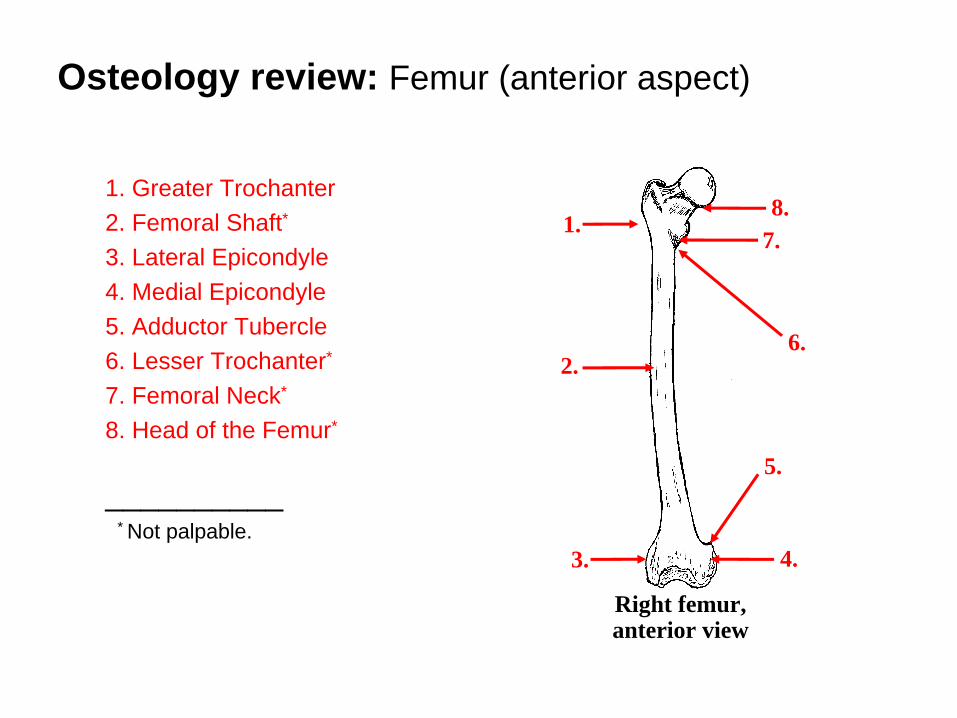
Osteology review: Femur (anterior aspect)
1. Greater Trochanter2. Femoral Shaft*
3. Lateral Epicondyle4. Medial Epicondyle5. Adductor Tubercle 6. Lesser Trochanter*
7. Femoral Neck*
8. Head of the Femur*
__________* Not palpable.
4.3.
2.
8.7.
6.
1.
5.
Right femur, anterior view

Osteology Review: Femur (Posterior Aspect)
1. Head of the Femur*
2. Femoral Neck*
3. Lesser Trochanter*
4. Medial Condyle5. Lateral Condyle6. Femoral Shaft*
7. Linea Aspera*
8. Greater Trochanter
_________* Not palpable.
5.
1.
3.
4.
6.
2.
8.
Right femur, posterior view
7.

As a general rule, the female patients will have a greater internal rotation angle than the male pelvis, and this factor will be taken into consideration during the modification process.
Cross section view female pelvis Cross section view male pelvis
Osteology review: Female vs. male pelvis
43 28 45 30

Osteology review: Pelvis (anterior aspect)
1. Iliac Fossa2. Anterior Superior Iliac Spine3. Anterior Inferior Iliac Spine4. Obturator Foramen5. Ischial Tuberosity6. Pubic Symphysis7. Acetabulum8. Sacrum
8.
7.
6. 5.
1.
2.3.
4.
Pelvis, anterior view

II. Patient Evaluation
Ischial Containment Prosthetics

Introduction
The following module focuses on patient prosthetic evaluation. It will help you evaluate the condition of the patient and the residual limb.
It is important that you not limit your evaluation to the residual limb. Rather, you should consider the whole person and how each aspect of this unique individual plays a role in selection of the appropriate prosthesis design.

Transfemoral evaluation: Record keeping
Use a Prosthetic evaluation form as a guide and to record essential details regarding the patient’s condition.
Fill in the personal patient information at the top of the page (address, cause and date of limb loss, weight, height, etc.).
Prosthetic evaluation form

Transfemoral evaluation: Clinical record keeping
It is also critical that the prosthetist keep and maintain clinical records regarding the patients’ condition (e.g., weight changes, skin condition, other medical complications). These records provide context for the patients changing medical and prosthetic needs, regardless of who is providing the medical care.

Examine the residual limb by palpation, identifying any sensitive areas.
Transfemoral evaluation: Limb sensitivity
Palpation of the residual limb

In order to determine tension values, evaluate the subcutaneous tissues of the residuum. Pinch the flesh with the thumb and the index finger. Measure the thickness of the fold. If it is less than 12mm. it is light; if it is 12mm. it is average; if it is greater than 12mm. it is heavy.
Transfemoral evaluation: Tension values
Determining tension values of thesubcutaneous tissues

Ask the patient to contract his limb muscles. Grasp the patient's residual limb with both hands and rotate the muscles around the femur. Gross motion or the feeling of softness indicates the musculature is soft. When the muscles are firm but can be moved, they are average. Long residual limbs with little or no shortening of the long muscles with the distal ends tied are usually classified as firm.
Transfemoral evaluation: Limb musculature
Evaluation of limb musculature

This is a good time to evaluate limb shape with femoral internal rotation. Instruct the patient to internally rotate his thigh while you evaluate the change in prominence of the anterior lateral aspect.
Note: If the anterior lateral aspect becomes prominent you will want to have the patient internally rotate his thigh once the plaster wrap has been applied.
Transfemoral evaluation: Limb shape

Measure the amount of hip extension. You will use this measurement later to determine how much flexion to place in the cast.
Have the patient stand in a place where he can support himself, preferably between parallel bars, and balance on the sound leg. The patient's head and torso must be held erect and the residual li b l d
Transfemoral evaluation: Measuring hip extension
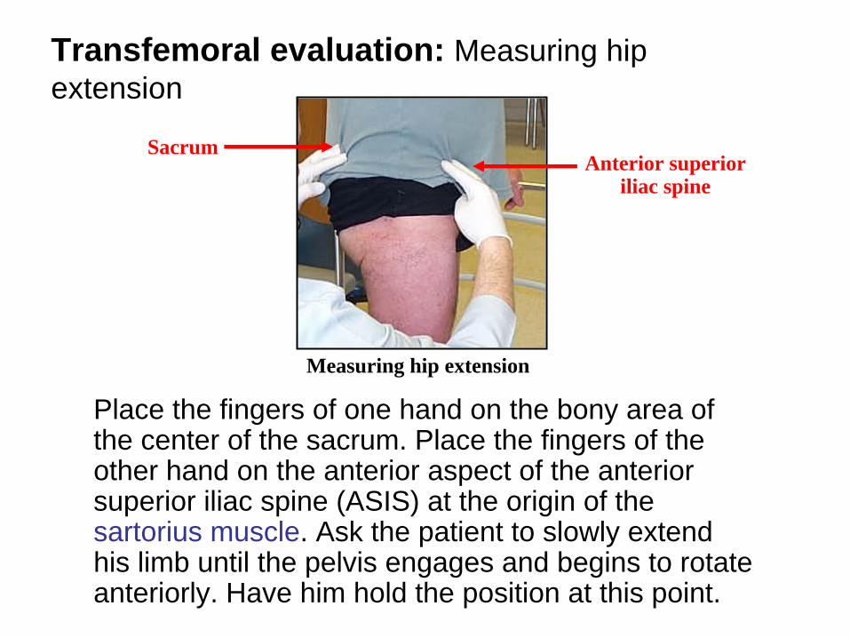
Place the fingers of one hand on the bony area of the center of the sacrum. Place the fingers of the other hand on the anterior aspect of the anterior superior iliac spine (ASIS) at the origin of the sartorius muscle. Ask the patient to slowly extend his limb until the pelvis engages and begins to rotate anteriorly. Have him hold the position at this point.
SacrumAnterior superior
iliac spine
Transfemoral evaluation: Measuring hip extension
Measuring hip extension
As long as the patient is able to place his limb in extension, no hip flexion contracture is present. A normal hip is capable of a maximum of 5o of extension.
If the patient is unable to extend his limb to a vertical or slightly extended position, evaluate the limb for a flexion contracture. To do so we recommend using the Thomas Test as described in the following slides.
Transfemoral evaluation: Hip extension

The Thomas Test is a specific test designed to detect flexion contractures at the hip. To perform this test have the patient lie supine on a firm surface. Ask the patient to bring his contralateral knee to his chest and hold it there with his hands.
Transfemoral evaluation: Flexion contractures
Patient position and movement for the Thomas Test
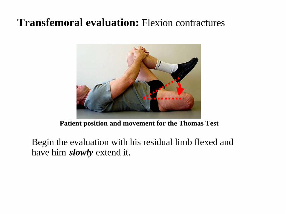
Begin the evaluation with his residual limb flexed andhave him slowly extend it.
Transfemoral evaluation: Flexion contractures
Patient position and movement for the Thomas Test

A fixed flexion contracture is characterized by the inability to fullyextend the residuum straight without arching the lumbar spine. Theextent of the hip flexion contracture can be determined by measuringthe angle between the table and the patient's residual limb. Use agoniometer to measure and record the attitude of the limb at this point.This will be the amount of flexion contracture present.
Transfemoral evaluation: Flexion contractures
Goniometer measurement
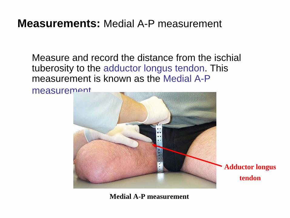
Measure and record the distance from the ischial tuberosity to the adductor longus tendon. This measurement is known as the Medial A-P measurement.
Adductor longus tendon
Measurements: Medial A-P measurement
Medial A-P measurement

Have the patient sit straight on a firm flat surface. Measure the distance from the surface to the adductor longus tendon as proximal in the perineum as possible.
Important Note: If you do not take the measurement proximal enough, the resulting A-P measurement may be too small, and can lead to a socket with an A-P dimension that is too tight.
Adductor longus tendon
Measurements: Medial A-P measurement
Medial A-P measurement

At this time a casting garment should be donned by the patient. You may sew your own elastic casting garment or buy it pre-made. Pre-made commercial garments are available in different sizes. Most patients fit into the smaller size, but patients with large residual limbs will require the larger size.
Fit the garment to the patient so that it fits snugly and to achieve some compression of the soft tissue.
Measurements: Casting garment

The casting garment is worn like a pair of short pants. There is an elastic and a cotton half of the garment. Place the elastic portion on the amputated side.
The elastic serves to solidify the soft tissue of the residual limb. In order to don the casting garment place a cotton pull sock on the patient's residuum first. The casting garment is then donned by the patient just like putting on a pair of
t
Patient with elastic garment
Measurements: Casting garment

Once the garment is donned, remove the pull sock while holding the proximal portion of the casting garment to keep it from sliding distally with the pull sock. By using this pull sock, it helps pull the proximal tissue into the casting garment and provides an accurate impression of the elongated soft tissues.
Measurements: Removing the pull sock

Align the weave of the casting garment horizontally to use the ribs as a horizontal reference while taking measurements.
Measurements: Removing the pull sock

The seam should be in contact with the perineum. The seam between the cotton and elastic portions should be vertical and at midline. To keep the elastic side from pulling the cotton side past the midline, it will be necessary to cut the cotton material on the lateral sound side and pull it tighter and make a knot in the material.
Donning the casting garment

In order to close the distal end of the elastic side, a "door" is made. This "door" is produced by cutting off the material anteriorly which is distal to the end of the residual limb. A flap will remain posteriorly. Pull the flap anteriorly to cover any exposed skin and tape it into place anteriorly.
Measurements
Cutting the “door” Taping the “door”

With the patient standing, find and mark ischial level on the posterior lateral aspect of the casting garment. Place an A-P caliper at ischial level and measure the distance from the rectus femoris muscle to the gluteal fold. Hold the caliper in the line of progression (parallel with the sagittal plane). Ask the patient to keep his leg muscules relaxed.
Measuring the lateral A-P
Lateral A-P measurement
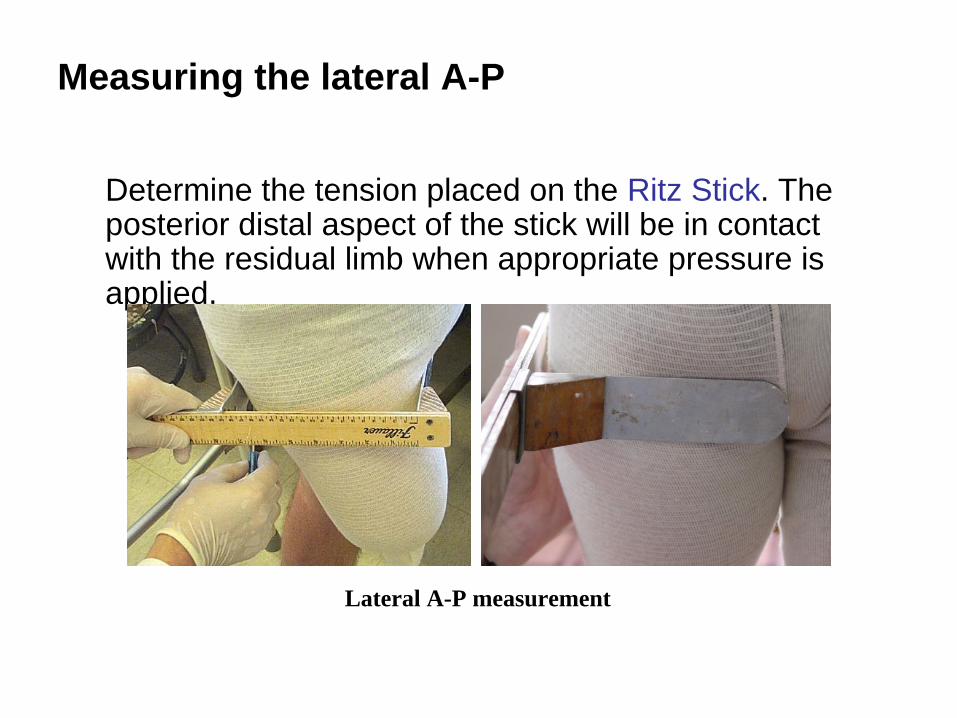
Determine the tension placed on the Ritz Stick. The posterior distal aspect of the stick will be in contact with the residual limb when appropriate pressure is applied.
Measuring the lateral A-P
Lateral A-P measurement

Note: An exception to this is the patient who has previously worn a prosthesis with the proximal brim too tight. This amount of pressure would result in a measurement that would be too tight for these patients The anterior blade should be in light contact with the anterior aspect of the thigh. Record the measurement.
Lateral A-P measurement
Measuring the lateral A-P

Special IC calipers have been developed to record the distance between the medial aspect of the ischium and the femur.
Ischial containment M-L calipers
IC M-L caliper Ipos adjustable IC M-L caliper

Note: When using the IC M-L caliper be sure that the long bar is parallel to the line of progression, and pressed smoothly against the lateral aspect of the femur, just below the greater trochanter. The mobile side of the IC M-L caliper allows the prosthetist to capture proximal M-L dimensions.
Ischial containment M-L calipers

Line A: Measure from the posterior-medial aspect of the ischium to the femur just bellow the greater trochanter. This represent the bony lock. Record the measurement while keeping the caliper in place.
Line A
Measuring the skeletal M-L
Posterior view/placement of the IC M-L caliper

Line B: To obtain a soft tissue M-L dimension, measure 5cm. distal to the skeletal M-L. Reverse the IC M-L caliper 180° such that the short bar is now placed on the lateral aspect of the femur and parallel to the LOP. Posterior view/placement
of the IC M-L caliper
5cm
.
Line B
Line A
Measuring the soft tissue M-L

Line B: This step will be done twice. First measure and record with light pressure on the soft tissues. This will be represent the smallest possible soft tissue M-L dimension of the socket. Second, ask the patient to contract his musculature, measure and record once again. The finished socket should not be wider than this M-L dimension.
Posterior view/placement of the IC M-L caliper
Measuring the soft tissue M-L

With the patient standing, carefully place a Ritz Stick medially in the patient's perineum until it rests primarily on the pubic ramus. Gently move the distal plate of the Ritz Stick proximally until it lightly contacts the distal end of the residual limb. This measurement is the limb length.
Measurements: Limb length and femur length
Limb length

Note: If the patient has more than 6mm. of soft tissue distal to the end of the femur, a femur length is necessary as well. Measure the amount of soft tissue distal to the cut end of the femur. The soft tissue should have light support when this measurement is taken. This measurement will go in the femoral length box.
Measurements: Limb length and femur length

With the patient standing, use a tape measure to measure from the sound side ischial tuberosity to the floor with the patient's shoe off.
This will be used to determine the overall length of the prosthesis.
Measurements: Ischial tuberosity to floor
Leg length

Use the ischial level mark on the lateral side as a reference.
Measurements: Circumferences

Make a mark 25mm., 50mm., 75mm., 100mm., etc., distal to ischial level on the casting garment of the residual limb.
Measurements: Marking circumferences

Use a soft tape measure to take skin tight circumference measurements at each of the above levels. Use the horizontal weave lines of the casting garment to ensure you are taking the measurements parallel to the floor. Only go as far as the tape will lay flat against the patient’s skin.
Measurements

Measure the sound side of the patient’s medial tibial plateau to floor with the shoe off. This measurement will be used later to calculate the height of the prosthetic knee.
Record the patient's shoe size and heel height.
MTP
Floor
Measurements: MTP-to-floor
MTP-to-floor measurement

Ischial Containment Prosthetics
III. Prosthetic Casting Techniques

Introduction
Now that the necessary measurements and patient evaluations have been completed, you are ready to take an impression of the residual limb utilizing a series of steps and techniques that will be described in this module.

In the past, hand casts of the transfemoral residual limb yielded models which were grossly oversized, therefore making it difficult for even the experienced prosthetist to modify.
The casting technique described here yields a model which is much closer to the desired dimensions and captures the appropriate contours needed to meet the objectives of skeletal contour, muscle contour, and stability of the socket-limb interface.
Casting

1. Patient measurement form
2. Indelible pencil 3. Ritz Stick 4. A-P calipers 5. Tape measure 6. Casting garment7. Cotton pull sock
7. 10cm. Elastic plaster 8. 10cm. Rigid fast-setting
plaster9. 13.5cm. Rigid fast-
setting plaster10. Bucket 11. Masking tape
Casting materials

Outline the lateral distal femur using indelible pencil.
Mark other sensitive areas identified during the evaluation.
Casting: Marking the distal end of the femur
Marking the distal end of the femur

Practice the hand placement to familiarize yourself with the anatomical structures of the ischial tuberosity and femur. It is easier to palpate bony structures before applying the plaster bandages.
Casting: Hand placement
Practicing hand placement
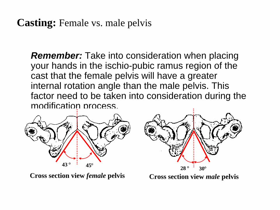
Remember: Take into consideration when placing your hands in the ischio-pubic ramus region of the cast that the female pelvis will have a greater internal rotation angle than the male pelvis. This factor need to be taken into consideration during the modification process.
Casting: Female vs. male pelvis
Cross section view female pelvis Cross section view male pelvis
43 28 45 30

Begin by wrapping residual limb from medial to lateral, beginning at the ischial level and proceeding distally.
Take care not to pull the adductor longus area laterally when applying the plaster.
Lateral view
Casting: Wrapping the residual limb

If available, apply fast setting (non-elastic) plaster over the elastic to act as reinforcement and to enable the prosthetist to provide proper contours on the impression. Elastic plaster does not retain concave contours.
Anterior view
Casting: Wrapping the residual limb

Apply a splint consisting of three layers of 13.5cm. fast-setting plaster through the perineum extending at least 13.5cm. anteriorly and posteriorly. A 50cm.-long splint is adequate for most patients.
Casting: Applying the plaster bandages

Pull the perineal splint up snugly to ensure contact with the pubic ramus. Pull the posterior aspect of the splint in a slight lateral direction in order to follow the ischio pubic ramus. Pull the anterior section straight up toward the umbilicus to prevent undo pressure on the adductor longus.
Note: It is important that the amputee only abduct the limb enough for the plaster to be applied.
Casting: Applying the plaster bandages

At this point, instruct the patient to adduct his limb and to keep flexion attitude at a comfortably extended position.
Casting: Positioning the limb
Patient with residual limb in adduction

Wrap a 13.5cm.-long plaster bandage around the entire pelvis at trochanteric level and firmly secure the wrap as it overlaps. The pelvic wrap is one layer thick. It is important to pull the pelvic wrap tight in order to achieve contact with the trochanter.
Casting: Positioning the limb

The cast is completed by plastering the entire hip area of the amputated side from anterior mid-line to posterior mid-line.
Casting: Wrapping the hip area
Wrapping the patient’s hip area

The casting procedure described uses two practitioners. The prosthetist behind the patient will place one hand firmly against the medial aspect of the ischium while applying a counter force over the femur.
Casting: Capturing the M-L dimension
Two-person hand-casting technique

An important goal of casting is to capture an accurate replica of the distance between the ischium and the greater trochanter (M-L dimension).
Casting: Capturing the M-L dimension
M-L dimension on a skeletal model
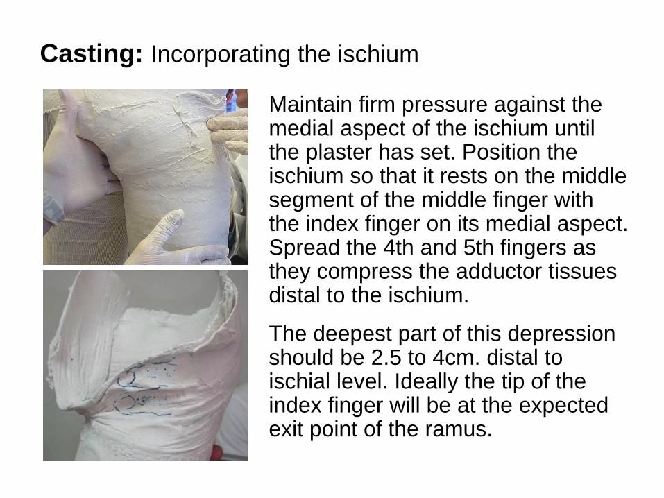
Maintain firm pressure against the medial aspect of the ischium until the plaster has set. Position the ischium so that it rests on the middle segment of the middle finger with the index finger on its medial aspect. Spread the 4th and 5th fingers as they compress the adductor tissues distal to the ischium.
The deepest part of this depression should be 2.5 to 4cm. distal to ischial level. Ideally the tip of the index finger will be at the expected exit point of the ramus.
Casting: Incorporating the ischium

If the pelvic wrap does not pull into the trochanter, you should indent the cast using one finger to achieve bony contact.
Casting: Lateral molding

Instruct the patient to abduct his thigh slightly until you feel the distal femur move to the lateral soft tissue boundary. Resist any further motion of the femur by pressing against the lateral aspect with your hand flat against the cast. The base of your hand should be 2.5cm. proximal to the cut end of the femur and should give a slight flattening of the posterior lateral aspect of the cast extending proximally to your finger
Casting: Proximal-medial molding

As the amputee begins this abduction motion his adductors relax allowing your medially placed hand to sink into the adductors distal to the ischium as well as rendering the ischial tuberosity accessible to palpation. To achieve proper medial proximal contouring, the relaxation of the adductors is crucial.
Casting: Proximal-medial molding

The second practitioner is positioned in front of the patient molds the area of the femoral triangle by massaging the plaster with emphasis at ischial level slightly lateral to the adductor longus.
Avoid applying pressure in the area of the anterior lateral aspect as this may cause the ischium to be displaced medially in the completed socket, especially if the amputee has firm thigh musculature.
Anterior lateral aspect
Casting: Molding the femoral triangle

Note: If femoral internal rotation causes the anterior lateral aspect to become prominent, it is advisable to instruct the patient to internally rotate the thigh while the plaster is wet in order to ensure proper contour. Internally rotating the thigh will also produce a rectus channel of the depth required for proper anterior wall contouring.
Casting: Depth of the rectus channel

Mark a line indicating line-of- progression onto the distal end once the plaster has set. Position the patient standing erect, with the pelvis "squared off” from the prosthetist's perspective. Mark the line-of- progression using an indelible pencil and straight edge.
Casting: Establishing the line-of-progression

Remove the impression by cutting the garment and plaster wrap encircling the pelvis, over the sound side leg, with plaster scissors.
Casting: Removing the impression

Evaluate the impression. The impression length should be at least as long as the measured limb length. Measure the length from the lowest point of the medial wall to the end along the central axis.
Casting: Evaluating the impression

Ischial Containment Prosthetics
IV. Modifications of Positive Mold

Introduction
The purpose of the modification process is to create a mold for the inside configuration of the socket. This is accomplished by removing and adding plaster in areas as required, and creating an overall shape and volume that is conducive to accommodating the firing muscles and that possesses the overall volume necessary to maintain suction suspension.

Remove the garment from the impression. Outline the area where the ischial tuberosity should be located using the finger indentation and the measured A-P dimension as a guide. Also mark the adductor longus position.
Ischial tuberosity
Adductor longus
Prepare to fill the impression

Mark a point on the medial shelf 2.5cm. medial to the adductor longus tendon. Next, draw a line parallel to the Line-of-progression (LOP) through this point. Trim along this line with bandage scissors.
Prepare to fill the impression
QuickTime™ and aTIFF (LZW) decompressor
are needed to see this picture.
Trimming off excess plaster from the medial side and matching it to the LOP established during the casting process
QuickTime™ and aTIFF (LZW) decompressor
are needed to see this picture.

Now close the medial aspect with two layers of plaster bandage. Use a flat surface to form the medial wall. The LOP should be parallel to the flat surface.
Prepare to fill the impression
QuickTime™ and aTIFF (LZW) decompressor
are needed to see this picture. QuickTime™ and aTIFF (LZW) decompressor
are needed to see this picture.
Preparing the medial overhang
QuickTime™ and aTIFF (LZW) decompressor
are needed to see this picture. QuickTime™ and aTIFF (LZW) decompressor
are needed to see this picture.

Apply a parting agent. The cast will be placed in bench alignment prior to being filled. The cast should be set in approximately 5
of
flexion or the measured flexion contracture plus 5.
This is to allow the amputee to take a sound side step without excessive lordosis in addition to placing the hip extensors on stretch, thus improving knee stability through out stance phase.
Prepare to fill the impression
Incorporating 5o of flexion

The normal mechanical axis of the lower limb is such that a line drawn through the femoral head will extend through the distal femur and down through the center of the ankle (i.e., Long’s line).
The femoral head is assumed to be at the bisection of the distance between the ischium and trochanter.
Fill the impression
QuickTime™ and aTIFF (LZW) decompressor
are needed to see this picture.
Incorporating adduction angle
QuickTime™ and aTIFF (LZW) decompressor
are needed to see this picture.

Note: This normal alignment is desirable in the case of the above knee amputee but not always attainable, especially in the case of a short, fleshy residual limb. Every effort should be made to achieve maximum adduction without crossing the vertical line. Optimal adduction improves the function of the hip abductors.
Fill the impression
Checking the amount of adduction angle

Fill the cast with plaster so the top of the plaster will be perfectly flat. Install a removable mandrel which extends vertically from the cast.
If a large amount of flexion is required, position the cast in a more vertical position with the mandrel representing the desired flexion. This will make vacuum forming easier (the cast will stand straight on the plate).
Fill the impression
QuickTime™ and aTIFF (LZW) decompressor
are needed to see this picture.
QuickTime™ and aTIFF (LZW) decompressor
are needed to see this picture.

Prior to stripping the cast, transfer the LOP through the plaster bandage to the plaster model using an awl. Split plaster bandage from plaster model. Re-establish indelible markings.
Cast modifications: Stripping the positive model

Identify ischial level and establish the actual and desired limb length. In patients with redundant tissue, it would not be unusual to experience elongation of the impression. Evaluate the discrepancy between the anatomical residual limb length and the length of the positive mold. Split the difference for the desired limb length.
Cast modifications: Establishing the ischial level

Establish ischial level around the perimeter of the cast with indelible pencil. The model must be in the desired (previously established) flexion and adduction angles as the ischial level is established.
Cast modifications: Establishing the ischial level

Mark with an indelible pencil 5cm. proximal to ischial level at the lateral 1/3 of the coronal diameter (M-L), then gradually descending to the anterior medial corner. This will serve as a guide for establishing the desired trim lines for the socket.
Anterior view
Ischial level
Lateral third
5cm.
Establish trim lines: Anterior
Anterior view

Mark with an indelible pencil 8cm. proximal to the ischial level. This will serve as a guide for establishing the desired trim lines for the socket.
Ischial level
Lateral view
8cm.
Establish trim lines: Lateral
Lateral view

Mark with an indelible pencil 2.5cm. proximal to the ischial level. This will serve as a guide for establishing the desired trim lines for the socket.
2.5cm.
Establish trim lines: Posterior
Ischial level
Posterior viewPosterior view

Continue the trim line from the posterior medial corner to the most distal aspect on the medial wall and connect to the anterior medial trim line.
Medial view
Posterior medial corner
Establish trim lines: Medial
Ischial level
Medial view

Take outside calipers and record the lateral A-P dimension of the unmodified plaster model. Measure this from the anterior aspect of the model to the posterior aspect of the model at ischial level. The plaster model will be significantly oversized in relation to your desired (recorded) lateral A-P dimension.
Cross section at ischial level
Lateral A-P dimension
Lateral view of positive mold

To reach your goal for the lateral A-P dimension, remove plaster from the posterior aspect of the plaster mold. Concentrate your modifications at the ischial level and gradually blend to the posterior medial and posterior lateral dimensions.
Cross section at ischial level
Posteriormedialcorner Posterior
lateralcorner
Cast modifications
QuickTime™ and aTIFF (LZW) decompressor
are needed to see this picture.
Posterior lateral corner
QuickTime™ and aTIFF (LZW) decompressor
are needed to see this picture.

When viewed in the transverse plane, this modification will look similar to a U-shape with the closed end of the U being the measured point of the lateral A-P dimension. The apex of the U is at the M- L bisector.
Cross section at ischial level
Cast modifications
Posterior-medial view

Once your lateral A-P has been achieved and you have worked to uniformly remove material from both the posterior medial and posterior lateral aspects, flatten the posterior shelf perpendicular to the medial shelf or LOP. This shelf should be no more than 1.5cm. in width at the M-L mid-line.
1.5cm.
Cross section at the ischial level
Med
ial
Lat
eral
Anterior
Cast modifications
QuickTime™ and aTIFF (LZW) decompressor
are needed to see this picture.
Establishing the posterior shelf
QuickTime™ and aTIFF (LZW) decompressor
are needed to see this picture.

Proximal to your established trim lines, flatten anterior surface parallel to posterior shelf (or perpendicular to medial shelf).
Cast modifications
Flattening the anterior-posterior surfaces
Med
ial
Lat
eral
Anterior

Transfer your circumference levels onto the posterior aspect of the plaster model beginning 2.5cm. distal to ischial level, then 5cm., 10cm., 15cm., etc. according to the length of the residual limb.
Note: This manual describes the technique for fitting a total contact suction interface. Tension values will be based on your initial patient evaluation. A reduction chart is provided for your reference.
Cast modifications: Re-establish circumferences
QuickTime™ and aTIFF (LZW) decompressor
are needed to see this picture.
QuickTime™ and aTIFF (LZW) decompressor
are needed to see this picture.

The plaster model should still be oversized at this point in the modification process, which will help you properly shape it for function and patient comfort.
Residual Limb MusculatureLevel Soft Average FirmIschial 2.5cm. 28mm. 2.5cm.50mm 2.5cm. 28mm. 12mm.100mm 2.5cm. 28mm. 12mm.
Cast modifications: Tension values

This quadrant proximally cups around the trochanter to provide a cosmetic transition and volume control. Distally, it has a posterior-lateral flattening for the femur to act when maintaining knee stability during heel strike.
The posterior-lateral wall also provides a surface for the femur to work against, and creates a gluteal channel proximally to accommodate movement.
Cast modifications: Posterior lateral quadrant

This area is important for femoral stabilization during stance phase.
Begin by modifying the posterior lateral aspect of the plaster model. Flatten this area in approximately a 45
angle
off the LOP.
A common error made during this modification is neglecting to carry this flattening to the mid-sagittal line of the plaster model.
Incorrect modification
Correct modification
Late
ral
Late
ral
Med
ial
Med
ial
Anterior
Anterior
LOP
LOP
Cast modifications: Posterior lateral quadrant

The medial wall is defined by the patient’s pelvic geometry, and is usually internally rotated off the LOP. The medial angle loads the adductors and maintains a firm lateral wall contact, which is critical during early stance phase. The medial brim also plays a part in rotational control. If it is too loose it may result in a lack of contact and consequently may allow “whips” during swing phase or discomfort during stance phase.
Cast modifications: Posterior medial quadrant

This area is important for ischial support and soft tissue stabilization.
The posterior medial quadrant is composed of a triangular area bounded by the semitendinosis posteriorly, the gracilis anteriorly, and the inferior pubic ramus superiorly.
The deep muscle of the adductor magnus occupies the floor of this triangle
Medial view
Gracilis Adductor Magnus
Semi- tendinosis
Cast modifications: Posterior medial quadrant

Removal of plaster over this sub-ischial triangle compresses and increases loading of soft adductor tissues. This provides excellent soft-tissue stabilization, especially in early stance phase. The deepest point of this modification should be approximately 4 to 6cm. distal to the ischial tuberosity.
A generous outward radius from the deepest point of this triangle to the ischial tuberosity is required and will be effected by the ischio-pubic ramus angle.
Posterior-medial quadrant
Cast modifications: Posterior medial quadrant

When viewed from the transverse plane, this modification will have an internally rotated position relative to the LOP. As previously mentioned, the amount of internal rotation will vary depending on the anatomical structure of the patient.
Late
ral
Med
ial
Anterior
LOPCross section of pelvis at ischial
level inside IC socket
Female
Male
Cast modifications: Posterior medial quadrant
Cross section view female pelvis43 45

As a general rule, the female patients will have a greater internal rotation angle than the male pelvis, as illustrated above. Re-evaluate the circumferences.
Cross section view female pelvis Cross section view male pelvis
43 28 45 30
Cast modifications: Posterior medial quadrant

This area is important for allowance of muscular function in early swing phase, weight bearing in early stance phase, and rotational control throughout gait. Adductor relief is important for socket comfort and to prevent the occurrence of adductor rolls.
Anterior view
Ischiallevel Lateral
wall
Cast modifications: Anterior-medial quadrant
Anterior view

The purpose of the Scarpa’s triangle is to apply pressure against the femoral bundle and to provide rotational control. It also helps to keep the ischium in position, but it is not as critical as it is in the quadrilateral socket.
In the IC socket, this function of the Scarpa’s triangle is accomplished primarily by the anterior-lateral quadrant. Anterior view
Cast modifications: Scarpa’s Triangle

Begin by establishing the ischial level on the anterior surface with an indelible pencil.
Divide the anterior aspect of the plaster model into thirds and delineate on the ischial line.
Project the lateral third delineation proximally 5cm. to the established trim line.
Ischial level
1/3 2/3 3/3Lateral third
Anterior view
Cast modifications: Scarpa’s Triangle
2.5 cm.

From a point 2.5cm. lateral to the anterior medial corner and at ischial level, draw a line 10cm. distal and perpendicular to the ischial line.
Connect the end points of the lines drawn in the previous two steps.
From the lateral third proximal delineation draw a line with a gradual descent to the anterior medial corner.
These lines indicate the boundaries of the femoral triangle and serve as a guide for shaping the area to a smooth contour.
Ischial level
2.5 cm.
10cm.
Cast modifications: Scarpa’s Triangle
Anterior view
This area accommodates the anterior musculature including the rectus femoris and the tensor fascia lata proximally. It is important to evaluate the depth of this channel when the patient holds his limb internally rotated. This modification is critical in providing counterpressure to maintain ischial contact with the medial wall. If it is too loose the ischium may slip off and lateral rotation at heel strike may result. If it is too tight the ischium may ride above the brim medially.
Cast modifications: Anterior-lateral quadrant

To determine the depth of the rectus channel, place the straight edge of a combination square on the apex of the rectus femoris area and perpendicular to the medial wall. Measure the distance from the straight edge to the deepest point of the femoral triangle. This dimension should correspond closely to the values given in the following chart.
Cast modifications: Anterior-lateral quadrant

The rectus channel depth dimension should correspond closely to the values given in the following chart.
Cast modifications: Anterior-lateral quadrant
Residual Limb MusculatureSoft Average Firm
Anterior 2cm. 2.5cm. 2.5cm. Mid line 2cm. 2cm. 2.5cm. Posterior 7mm. 2cm. 2cm.
Position of Greater Trochanter

Remove plaster from the lateral aspect of the model at ischial level. This modification will assist in coronal stability that cannot be achieved during the casting process.
Anterior view
Lateral wall
Cast modifications: Skeletal and soft tissue M-L
Ischial level

Compare your positive model M-L dimension to your skeletal and soft tissue M-L dimensions.
To reach your goal for the M-L dimension, remove plaster from the lateral wall. The remainder of the lateral wall should be flat and follow the contours of the patient's femur.
Anterior view
Lateral wall
Cast modifications: Skeletal and soft tissue M-L
Ischial level

Removal of plaster from the soft tissue of the medial distal aspect of the plaster model will result in total contact and improved adduction capabilities in the definitive socket. The amount of material removed will be greater with patients having excess soft tissue and heavy subcutaneous tissue.
Posterior view
Ischial level
Medial distal
Cast modifications: Medial distal

Position plaster model in proper adduction attitude. Remove approximately 6mm. of plaster proximal to ischial level.
Ischial level
Cast modifications: Proximal lateral
Before modification After modification
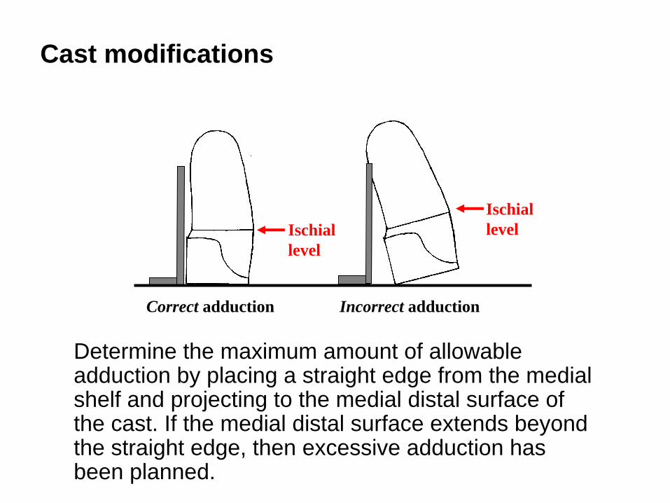
Determine the maximum amount of allowable adduction by placing a straight edge from the medial shelf and projecting to the medial distal surface of the cast. If the medial distal surface extends beyond the straight edge, then excessive adduction has been planned.
Ischial level
Correct adduction Incorrect adduction
Cast modifications
Ischial level
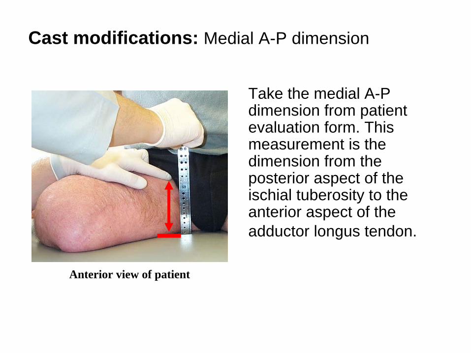
Take the medial A-P dimension from patient evaluation form. This measurement is the dimension from the posterior aspect of the ischial tuberosity to the anterior aspect of the adductor longus tendon.
Anterior view of patient
Cast modifications: Medial A-P dimension

Set the outside calipers to this measured medial A-P dimension. Position one leg of the caliper on the anterior medial aspect of the cast (adductor longus area) at ischial level. Mark the posterior medial area, which represents the posterior edge of the ischium.
Cast modifications: Medial A-P dimension
Medial A-P dimension

Mark a point approximately 2.5cm. anterior to the posterior medial area established in the previous step.
To estimate the amount of ischial containment, transfer an approximate medial trim line from the posterior wall to the newly established 2.5cm. anterior mark
Cast modifications: Medial A-P dimension

Note: Variations in pelvic structure affect the amount of ischial containment. In the female patient with a small medial A-P dimension, 2.5cm. of ischial containment can be difficult to achieve due to the wide angle of the ischio-pubic ramus. A smaller amount of containment must then be used. As a general range of 18mm to 30mm of ischial containment can be used and should have been evaluated during casting.
Cast modifications

Finish the modification by applying a generous radius of plaster to fill the area of the finger depressions. This also will allow room for the exit of the adductor tendons that attach to the ischial tuberosity and inferior ramus.
Cast modifications

Ischial Containment Prosthetics
V. Test Socket Fabrication

Introduction
The purpose of the fabrication process is to create a test socket that will enable the prosthetist to evaluate the fitting and adjustments of the IC socket prior to final lamination.

Test socket fabrication procedure
A test socket fabricated of a clear thermoplastic material (e.g., Durr Plex) is the first step required to achieve a optimal fitting of the residual limb. The test socket is used to perform the necessary adjustments/modifications on the socket as well as its connection to modular components (i.e., alignment) before continuing with the fabrication of the definitive device.

The test socket enables the prosthetist to evaluate and adjust the fit of the socket prior to the process of static and dynamic alignment of the prosthetic device. Thermoplastic material used for such container should be:
• Clear (see through)• Rigid enough to carry the body weight and
keep the ischium containment (bony-lock) without any distortion.
Test socket fabrication procedure

Deep-drawing vacuum kit with frame
Test socket fabrication procedure: Equipment and tools

Test socket fabrication procedure: Equipment and tools
Deep-drawing vacuum kit with frame

Test socket fabrication procedure: Equipment and tools
Suction platform

Test socket fabrication procedure: Equipment and tools
Oven with circulation air and floor-covered with Teflon foil

Test socket fabrication procedure: Equipment and tools
Oven with circulation air and floor-covered with Teflon foil
Vacuum kit with frame placed inside the oven
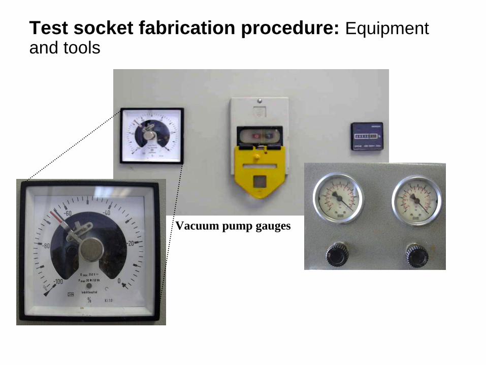
Test socket fabrication procedure: Equipment and tools
Vacuum pump gauges

Test socket fabrication procedure: Equipment and tools
Connection of the vacuum pump to the suction platform
Test socket fabrication procedure: Equipment and tools
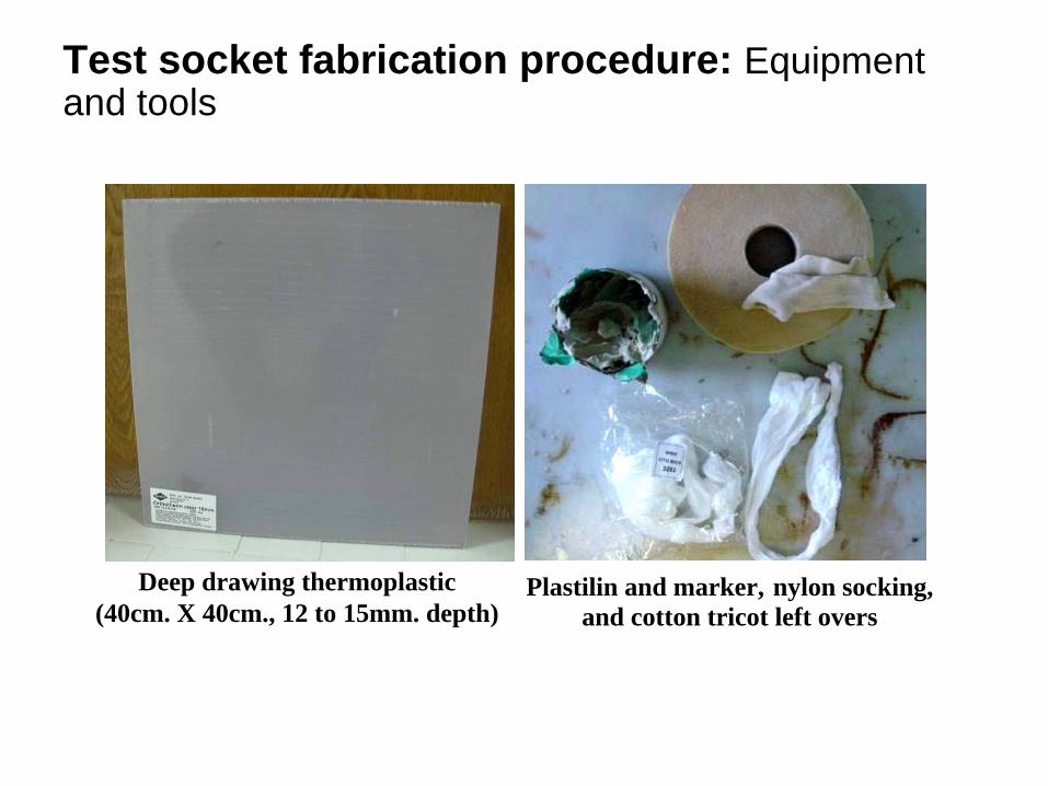
Deep drawing thermoplastic(40cm. X 40cm., 12 to 15mm. depth)
Plastilin and marker, nylon socking, and cotton tricot left overs

Test socket fabrication procedure: Equipment and tools
Oscillating saw, Ventil-Dummy, and
knife
Protective gloves Compressed air and tools for plaster removal

Test socket fabrication procedure: Production
Proof the plaster positive•Shape•Dimensions•Ventil position• Adapter connection

Proof the plaster positive • It is set in the middle of the
platform• Its covered with a nylon
sock• The space between
platform and proximal model surface is filled with cotton left-over / foam-ring
Test socket fabrication procedure: Production
Plaster positive covered with nylon sock
Cotton left-over/ foam-ring
Deep-drawing platform

Apply finish to the plaster positive (fly- grid is sufficient)
Test socket fabrication procedure: Production

Check surface and position of the ventil.
Test socket fabrication procedure: Production
•Is it properly aligned with the adapter position?•Does the position respond to the patient needs?
Positioning of the ventil
Plaster
Surface features of the ventil
Bundesfachschule für Orthopädie-Technik

Remove the cover (protection foil) from the thermoplastic plate and set it in the frame.
Test socket fabrication procedure: Production
Removal of the protection foil

Test socket fabrication procedure: Production
Prepare insides of the frame with talcum and set plate in the frame.
Talcum powder applied to frame Placing the thermoplastic

Test socket fabrication procedure: Production
Apply talcum powder to both surfaces of the insides of the frame which will be in contact with the thermoplastic prior to locking the frame to secure the plate.
Talcum powder is applied to both contact surfaces of the frame
Locking the frame

Place the deep-drawing frame with thermoplastic onto the carry-bars in the oven.
Test socket fabrication procedure: Production
Deep-drawing frame with secured thermoplastic
Carry bars hold the frame in place in the oven

The table below provides approximate oven temperature and dwelling-times for different types of materials.
Test socket fabrication procedure: Production
Material Oven-temperature °C Dwelling-time(for mm thickness)
MO clear 200 10min (10mm)GOPLEX 170 20min (12mm)THERMOLYN 180 24min (12mm)ORTHOTHERM 170 20min (12mm)
IPOLEN 180 17min (8mm)MO plus 275 11min (11mm)THERMOLYN LPDE 180 15min (6,3mm)THERMOLYN flexible 180 15min (8mm)
THERMOFLEX 180 9min (12mm)MO soft 175 10min (12mm)THERMOLYN soft 180 24min (12mm)RAFLEX 140 14min (12mm)

Place the deep-drawing frame with the material into the precisely heated oven according to the technical information of the specific material.
Test socket fabrication procedure: Production
Set the alarm time according to the technical information of the specific material.
Setting the oven temperature
Setting the oven timer
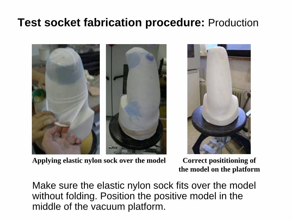
Make sure the elastic nylon sock fits over the model without folding. Position the positive model in the middle of the vacuum platform.
Test socket fabrication procedure: Production
Applying elastic nylon sock over the model Correct posititioning of the model on the platform

Compensate for eventual negative spaces between the plaster and the platform using cotton tricot.
Test socket fabrication procedure: Production
Plaster positive covered with nylon sock
Cotton left-over/ foam-ring
Deep-drawing platform
Using cotton tricot to compensate for eventual negative spaces

Vacuum Tip: If the base of the positive model is too flat the vacuum might press the model down on the platform’s sealing, which may could block the suction of the vacuum.
Test socket fabrication procedure: Production
Safety Note: Always wear a long-sleaved working coat and use heat protective gloves when handling the metal frame/thermoplastic material. This rule applies whether placing the frame in or taking it out of the heated oven.
Always wear a long-sleave working coat and heat protective gloves

The moment the material is bending down 10 to 15cm it is ready for the performance.
Note: The recommended duration of each material should be controlled under real conditions.
Test socket fabrication procedure: Production
Heated thermoplastic ready for performance

Center the thermoplastic over the model, convex side up (as shown below), and work the material in the frame carefully down to the platform.
Test socket fabrication procedure: Production
Applying the heated thermoplastic over the positive model

Work the material in the frame carefully down to the platform.
Test socket fabrication procedure: Production
Working the heated thermoplastic down to the platform

When full contact is applied between the platform sealing and the thermoplastic, carefully start alternating increasing suction and support the material to form the model without folding.
Test socket fabrication procedure: Production
Finishing the form of the model without any folding of the thermoplastic

Use the bar of a screw driver or a cotton string to form the ventil dummy into the hot thermoplastic.
Test socket fabrication procedure: Production
Forming the ventil dummy while the thermoplastic is still hot

Continue vacuum suction until the model is completely cooled. Take the cooled frame off the vacuum platform and relief the frame.
Test socket fabrication procedure: Production
Removal of the frame from the vacuum platform

Test socket fabrication procedure: Production
Removal of the frame from the vacuum platform

Cut the material along the trim line of the proximal container aspect with the oscillating saw.
Test socket fabrication procedure: Production
Marking of the trim line

Carefully break out the plaster with the compressed air tool, minding the integrity of the inner-container surface.
Clean and dry the container.
Test socket fabrication procedure: Production
Common tools for breaking out plaster

Use a rooter machine to adjust the proximal trim- line.
Test socket fabrication procedure: Production
Adjusting the proximal trim line with a rooter machine

Open the space where the ventil dummy was located, making sure that the opening does not become wider then the ventil dimensions.
Test socket fabrication procedure: Production

Test socket fabrication procedure: Production
Ventil components (disassembled)
Ventil components (assembled)

Test socket fabrication procedure: Production
Installing the ventil

Prove a proper match of the ventil on the container to ensure proper vacuum suspension.
Test socket fabrication procedure: Production
Checking the match of the the ventil on the container

Smoothen all edges/surfaces around the proximal trim-line.
Test socket fabrication procedure: Production

Ischial Containment Prosthetics
VI. Bench Alignment

Introduction
This module demonstrates how to place the socket on a modular or endoskeletal system using transfemoral alignment principles.

The alignment of the transfemoral prosthesis is extremely important in order to maximize the function of the amputee. The following alignment recommendations (sagittal plane) have been adapted from Radcliffe1 who has reported on alignment methods used in the United States and Europe.
Bench Alignment: Sagittal plane

A plumb line viewed from the lateral side of the socket passes downward from the center of the socket brim through the reference point on the knee (check the technical information of the manufacturer), and the reference point on the foot (check the technical information of the manufacturer). To achieve what may be described as a rolling action of the hip over the foot, the heel of the foot is elevated slightly in the reference position
Bench Alignment: Sagittal plane
Sagittal plane

The clearance under the heel is often called a safety factor. An increased clearance results in a more rapid transfer of weight to the ball of the foot and improves knee stability at heel contact.
10mm safety
Sagittal Plane
Bench Alignment: Safety factor

A spacer under the heel 6 to 10mm. thick at the time of bench alignment will give the amputee greatly increased knee security at heel contact. The prosthesis will not have its length increased with this procedure since the distance to the ball of the foot remains the same.
The alignment described allows for a stable knee during the major part of the stance phase and also allows the amputee to flex the knee at push off to initiate swing phase.
Bench Alignment: Safety factor

The knee axis is typically aligned in 5
external rotation, as necessary to prevent lateral movement (whip) of the foot in the swing phase.
Bench Alignment: Transverse plane

The socket should be set up in such a way that maximum femoral adduction is achieved.
Long's Line is especially useful in determining the amount of adduction which will be achieved as it is the only method which accounts for the distal femur. It should be assumed that the distal end of the femur will be against the lateral wall of the socket at midstance.
Distal end of the Femur
Coronal plane
Bench Alignment: Coronal plane

A limiting factor to adduction is the location of the distal medial socket relative to the mid-sagittal line.
If the socket crosses this line, and every attempt to minimize socket width in this area has been made, adduction should be reduced. Another limiting factor is residual limb length. A short femur will not be able to tolerate the forces generated during stance phase.
Coronal plane
Mid-Sagittal Line
Bench Alignment: Coronal plane
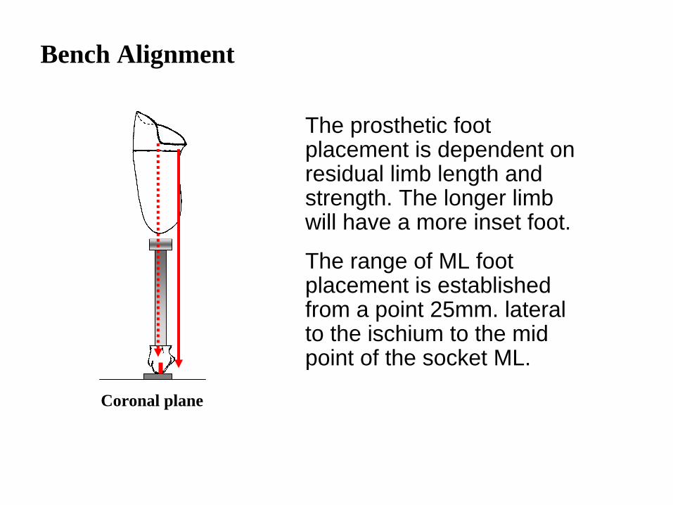
The prosthetic foot placement is dependent on residual limb length and strength. The longer limb will have a more inset foot.
The range of ML foot placement is established from a point 25mm. lateral to the ischium to the mid point of the socket ML.
Coronal plane
Bench Alignment

Ischial Containment Prosthetics
VII. Fitting the Test Socket

Introduction
The following section illustrates how to properly fit the prosthetic test socket. This process allows the prosthetist to evaluate fitting and make fine adjustments.
The test socket is used as an instrument to evaluate appropriate fitting prior to lamination and static and dynamic alignment.

The test socket is donned using a pull sock or an ace bandage. When pulling the residual limb in, note the tension of the socket by how much resistance is felt. The socket should go on easily with minimal resistance.
Fitting the test socket

Note: It is better to have a test socket which is too loose to hold suction than one which is too tight. The reason for this is that it is easy to identify and correct a loose socket but a tight socket is not always evident until the patient has worn the prosthesis for a while.
Fitting the test socket

Once the patient is in the test socket locate the three critical landmarks: adductor longus, ischium, and trochanter. It is extremely important that the evaluation be done with the socket maintained in the appropriate alignment. An abducted socket will cause the ischium to be out of the socket.
Start with the adductor longus. Make sure it is properly located in the anterior medial corner, in the channel provided. If it is not, the socket is rotated and must be redonned in the correct orientation.
Fitting the test socket

Fitting the test socket: Ischial-ramal containment
The amount of ischial containment is defined by the pelvic width and limb length. The are two types of containment:
• Anterior ramal containment • Proximal ischial containment
Male patients with a narrow pelvis may tolerate 25mm. of anterior containment, while male patients with wide hips may tolerate only 12mm.

Fitting the test socket: Ischial-ramal containment
The precise location of the exit of the ramus from the check socket is crucial for socket comfort. The brim angles and flaires should be adjusted to match the ramus for medial brim comfort.
Proximal ischial containment is determined by limb length. Short stumps may tolerate trimelines up to 50mm. proximal, while long residual limbs may prefer only 20mm. of containment.

Check the location of the ischium. This is difficult to palpate if ischial containment has been accomplished. Start by locating the ramus. It should be palpable just anterior to the trim line planned for ischial containment. Ask the patient to take the weight off the socket, and follow the ramus posteriorly to the ischium. The ischium should be on the shelf which has been shaped. The ramus should not be subjected to any vertical loading. This is assured by having the patient simulate single support while you palpate the ramus.
Last, check the location of the trochanter. There should be even, full contact between the skin and the socket over the entire lateral wall.
Fitting the test socket: Ischial-ramal containment

If the ischium is not in its proper location, check for tightness laterally, especially anterior laterally. Tightness in these areas will prevent the ischium from dropping into its proper location. This may also cause a lack of total contact distally because the limb is not fully in the socket. Heat and relieve the lateral wall as needed. Do not modify the medial aspect of the socket to rectify this problem.
Fitting the test socket: Ischial-ramal containment

If the patient complains of excessive pressure on the ischium, check that there is even contact with the socket. Increasing gluteal weight-bearing will sometimes help in relieving the ischium.
In cases where the ischium is too sensitive for comfortable weight bearing it may be necessary to provide a padded surface in the definitive socket.
This problem is most often encountered when working with a geriatric patient who has little muscle and/or subcutaneous tissue padding. Silicone padding in a laminated socket works well in these cases.
Fitting the test socket: Ischial-ramal containment

If there is gapping laterally, check that the ischium is properly contained. Increasing the pressure exerted medially on the ischium will have a greater effect on lateral gapping than filling in the lateral wall.
If the lateral gapping is isolated to the area just posterior to the trochanter, then selective modification to match this depression is indicated.
Fitting the test socket: Ischial-ramal containment

Evaluate the medial one-third of the proximal brim where the tissues exit the socket with regard to skin tension. This is especially important for soft, fleshy limbs in the area of the medial-gluteal tissues. As a result of ischial containment, these tissues are sometimes stretched over the brim and may lead to skin breakdown. This can be avoided by providing room within the socket for these tissues and by increasing the radius of the brim.
Total contact should be evaluated as well as the relief for the distal femur, as well as the compression over the medial-distal tissues.
Fitting the test socket
Evaluate for suction by sealing off the pull-hole with tape (first cover the sit with a patch of cotton stockinet). Evaluate the socket with the patient seated. Check that the anterior trim line is low enough to allow the patient to lean forward comfortably. However, if the brim is too low and does not contain the tissues up to the inguinal crease, it should be raised. If the anterior wall gaps check the width of the posterior shelf and reduce it accordingly.
Fitting the test socket
VIII. Static Alignment
Ischial Containment Prosthetics

Introduction
The following section illustrates how to conduct static prosthetic alignment for a transfemoral prosthesis. This process must take place before allowing the patient to take a step or proceeding to dynamic alignment.

Donning the Prosthesis
Inspect the person’s limb before donning the prosthesis. This will enable you to compare the condition of the limb before and after wearing the prosthesis. Make note of any troubled or sore areas. The perineum and the lateral distal femoral end are the most common areas of discomfort.
Inspecting the Limb

Donning the Prosthesis
It will not be necessary to frequently remove the prosthesis and inspect the limb as is done in a transtibial fitting. It is difficult and tiring to don and doff a transfemoral prosthesis, so you should do so only when absolutely necessary.

Static Alignment with Patient
If the height of the prosthesis is correct, the crests of the ilium will be level.
If the iliac crest on the affected side is higher, the prosthesis is too long and needs to be shortened. If the ipsilateral crest is lower, the prosthesis is too short.
Checking the Level of the Iliac Crests

Static Alignment with Patient
While ideally the limbs would have identical length, it is usually necessary for the transfemoral prosthesis to be slightly shorter in order to provide toe clearance during the swing phase. Try to minimize this difference. The final length determination will be made during dynamic alignment.

Static Alignment with Patient
If a change in length is necessary, slide spacers under the shorter side until the person feels comfortable and the iliac crests are level. Correct the height of the pylon this same amount.
Once the height is correct, you are ready to evaluate and adjust the alignment of the prosthesis.

Static Alignment with Patient
If the pylon is leaning posteriorly, the prosthetic heel may be too soft or the heel height of the foot may be incorrect for the shoe. This is the case, for example, if the foot was intended for a shoe with a higher heel.
Checking for Posterior Lean

Static Alignment with Patient
With an endoskeletal system, it may be acceptable for the pylon to have an anterior lean, because during the bench alignment, the pylon was leaned to position the knee with respect to the foot. No adjustment is necessary at this time if the socket, knee, and foot are correctly aligned relative to one another.

Static Alignment with Patient
In the coronal plane, the pylon should have a medial lean at the proximal end when the person stands with equal weight on each leg. If the pylon has a lean at midstance during dynamic alignment, it means the prosthesis has an improper amount of adduction built into the socket or alignment.

Static Alignment with Patient
If an improper adduction angle was aligned in the prosthesis, the foot will not fall flat on the floor during walking. As a result, shoes will wear unevenly and balance may be affected.
If there is a lean in the pylon during walking, the patient will walk on the inside or the outside border of the shoe and feel less stable.

Static Alignment with Patient
If the pylon is leaning medially, do not make a change at this time. This will be reevaluated during dynamic alignment.
Evaluating Medial Lean

Static Alignment with Patient
If the pylon is leaning laterally, you must correct this before proceeding.
Correct the lateral lean in the pylon by tightening the lateral proximal screw below the knee.
Evaluating Lateral Lean

Static Alignment with Patient
Note: Remember that making angular changes also affects the linear foot position. If there are great angular changes, you may need to correct the new linear position to get it within an acceptable range.

Static Alignment with Patient
Always have a plumb bob handy and know where the socket, knee, and foot are positioned with respect to one another!
Using a Plumb Bob

Static Alignment with Patient
If the static alignment is taking a long time or if the patient is feeling tired, be sure to offer breaks. Keep in mind, however, that it may be difficult for the person to sit down and get up repeatedly. With that, it is critical that you recognize and correct problems efficiently. If you need to remove the prosthesis to make adjustments and the limb has a tendency to swell, be sure to apply a compression material to the limb.

IX. Dynamic Alignment
Ischial Containment Prosthetics

Introduction
At this point, the prosthetist and amputee will begin the procedure of dynamic alignment. Dynamic alignment provides the opportunity to adjust the alignment of the prosthesis to obtain a satisfactory, efficient, comfortable, and cosmetically appealing gait.

Dynamic Alignment
As the prosthetist, you are responsible for diagnosing gait deviations in order to create the most comfortable and efficient gait possible for the person with whom you are working. You will need to effectively communicate with the person and make accurate observations in order to make decisions regarding the fit of the prosthesis, the proper alignment, and the functional capacity of the individual person. You need to understand the principles of normal gait so you can identify deviations and appreciate the penalty the person suffers with a gait that is less than optimal.

Dynamic Alignment
The prosthetist should develop a system for evaluating the gait stages and making the necessary changes in the prosthesis to optimize efficiency, stability, weight bearing, and cosmetic value. If at any point the prosthetist sees something that needs to be corrected, that adjustment should be made immediately. Always make the obvious alterations first, and then fine tune as needed to achieve the optimal gait.

Dynamic Alignment
You will often be faced with several possible causes for a problem; given that, you will need to make choices and reason out the best adjustment or solution. For example, you will evaluate areas of pressure and discomfort and diagnose the cause. You will be required to decide between possible solutions to these problems, including angular and linear alignment changes and socket fit changes.

Dynamic Alignment
Observation and diagnosis are essential to aligning a prosthesis. You need to observe from at least two vantage points: the sagittal plane, which is viewed from the sides, and the coronal plane, which is viewed from the front and back.
Sagittal Plane Coronal Plane

Dynamic Alignment
While observing deviations and considering their possible prosthetic solutions, be aware of non-prosthetic causes as well. While concomitant problems should never be used as an excuse for an ill-fitting prosthesis, be aware of them and how they may present during gait. Remember the history of the individual and consider all the conditions he may present. Always remember that the health and safety of the individual is paramount. Realize that stability must be provided through the prosthesis as much as possible and that the person may have inherent stability issues and require the assistance of mobility aids and strength and gait training.

Dynamic Alignment
A gait deviation is any gait characteristic that deviates from the normal pattern. Gait symmetry is a very important goal; the gait on the prosthetic side should closely match the gait on the contralateral side. Observe the timing of each part of gait and compare it to the other side. Look for smoothness of motion. Any change from the norm will look unnatural to the trained observer. A skilled prosthetist will recognize the deviations and promptly correct them.

Normal Gait
Prosthetic Side
Midline
Sound Side
A Normal Gait Pattern

Normal Gait: Stance Phase
There are different stages of the walking cycle. The stance phase is the period during which weight is borne on the limb.
Heel Strike Foot Flat Midstance Heel Off Toe Off

Normal Gait: Stance Phase
Stance phase consists of the following five subdivisions:
• Heel strike• Foot flat• Midstance• Heel off• Toe off

Stance Phase: Heel Strike
Heel strike is the instant the heel comes in contact with the ground.
Heel Strike

Stance Phase: Foot Flat
Foot flat is the point when the sole of the foot contacts the floor.
Foot Flat

Stance Phase: Midstance
Midstance is the point at which the body is directly over the supporting extremity.
Midstance

Stance Phase: Heel Off
Heel off is the point at which the heel of the supporting foot leaves the floor.
Heel Off

Stance Phase: Toe Off
Toe off is the point at which the toe of the supporting extremity leaves the floor.
Toe Off

Normal Gait: Swing Phase
The instant the toe of the supporting extremity leaves the floor, swing phase begins. This is a period of non-weight bearing.
Acceleration Midswing Deceleration

Normal Gait: Swing Phase
Swing phase consists of the following three subdivisions:
• Acceleration• Midswing• Deceleration
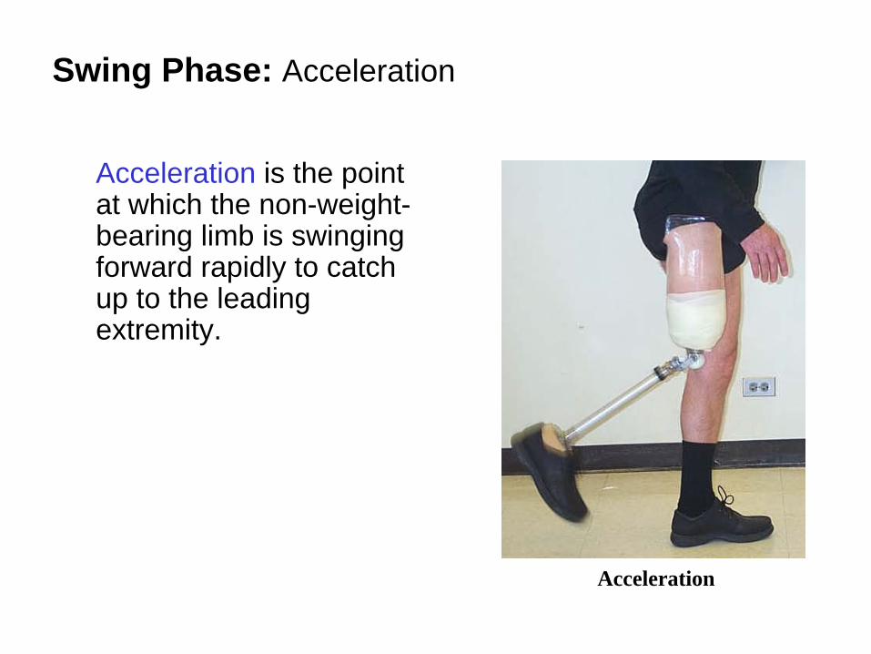
Swing Phase: Acceleration
Acceleration is the point at which the non-weight- bearing limb is swinging forward rapidly to catch up to the leading extremity.
Acceleration

Swing Phase: Midswing
Midswing is the point at which the swinging limb has caught up with the contralateral extremity.
Midswing

Swing Phase: Deceleration
Deceleration is the point at which the advancement of the limb begins to slow down in preparation for the next heel contact.
Deceleration

Heel Compression
There should be some compression of the heel (approximately 9mm.) of the prosthetic foot in order to absorb the shock during the loading response in early stance. Increased heel stiffness results in greater knee flexion forces and decreased shock absorption.
Heel Compression
Heel Compression
A softer heel is needed for transfemoral prostheses as compared to transtibial prostheses. However, if the heel is too soft, there will be too much compression. As a result, the motion from heel strike to foot flat will be delayed and not smooth. The heel will mash and the person will have to move his body forward over the foot, causing the early gait to appear very stiff. It will appear as if the person is stuck and cannot roll forward onto the foot. It is useful to look directly at the heel compression to identify this problem.

Heel Compression
A heel that is too stiff can lead to knee instability and be hazardous to the patient. It may also cause external rotation of the prosthetic toe portion of the foot at heel strike.
External Rotation of Toe at Heel Strike

Shoe Evaluation
The action of the prosthetic foot depends not only on the foot itself but also on the shoe. A stiff shoe heel will act like a stiffer heel of the foot, and a softer soled shoe will act like a softer heeled foot.
Evaluating the Shoe

Shoe Evaluation
The fit of the shoe affects the compression of the prosthetic heel. The shoe must not be so snug that it limits heel compression; it should not be so loose that the foot slides around. The shoe should be of good quality and should not be so worn that it affects the way the person walks with the prosthesis.
Snug Shoe Limits Heel Compression

Shoe Evaluation
Do not underestimate the importance of the foot– shoe variable in the fitting process. Spend time at this point ensuring that the combination is correct for the person. Prosthetists who overlook this element waste a great deal of time during dynamic alignment.

Stance Gait Deviations: Between Midstance and Toe-Off
Abrupt lack of support by the prosthesis or “drop-off” in last part of stance phase may result from a lack of anterior support. Possible causes of this include the following:
• Excessive anterior displacement of the socket over the foot (meaning the foot is too posterior)• Inadequate stiffness or length in the keel of the footLack of Anterior Support

Stance Gait Deviations: Between Midstance and Toe-Off
In the opposite situation, when there is excessive anterior lever arm, the patient feels that it takes too much effort to get over the front of the foot, almost as if he is walking uphill.
Excessive Anterior Lever Arm

Stance Gait Deviations: Between Midstance and Toe-Off
This excessive anterior lever arm can result from any of the following:• Excessive plantar flexion of the foot• Too much posterior displacement of the prosthetic knee relative to the foot and socket• Too much inherent stability

Stance Gait Deviations: Between Heel Strike and Midstance
During normal gait, the knee is in almost complete extension at heel strike. The instant weight is borne on the limb, there is a tendency for the knee to go into flexion. To control this tendency, the quadriceps muscles become active in their role as knee extensors.
The Quadriceps Act to Prevent Excessive Knee Flexion

Stance Gait Deviations: Between Heel Strike and Midstance
For the transfemoral amputee, however, the knee must not be allowed to go into flexion, because this will result in instability. With that, an extension moment must be maintained on the knee mechanism!
Knee Flexion Results in Instability

Stance Gait Deviations: Between Heel Strike and Midstance
Prosthetic causes of knee instability include the following:
• Lack of inherent stability in the knee mechanism • Lack of stability in the knee alignment (knee positioned posterior enough relative to the foot and interface)• Insufficient flexion in the interface (Note: Change this angle only if it was aligned improperly; it should be aligned in 5 degrees of flexion if there is no hip flexion contracture present.)• Excess firmness in the heel

Stance Gait Deviations: Between Heel Strike and Midstance
Amputee causes of knee instability include the following:
• Weak hip extensors• Severe hip flexion contracture

Stance Gait Deviations: Long Prosthetic Step
A long prosthetic step is seen when the amputee takes a longer step on the prosthetic side and a shorter step on the contralateral side.
Prosthetic Side
Sound Side
Midline
A Long Prosthetic Step

Stance Gait Deviations: Long Prosthetic Step
The primary prosthetic cause of a long prosthetic step is insufficient flexion in the socket. This defect may be acceptable if there is a large flexion contracture that cannot be accommodated.
The primary amputee cause of a long prosthetic step is a flexion contracture that cannot be accommodated.

Stance Gait Deviations: Uneven Arm Swing
An uneven arm swing is present when the arm on the prosthetic side is held close to the body during walking.
The primary prosthetic cause of an uneven arm swing is an improperly fitting interface. This may cause limb discomfort, which will result in this defect.

Stance Gait Deviations: Uneven Arm Swing
Amputee causes of an uneven arm swing include the following:
• Lack of good balance
• Fear and insecurity, accompanied by uneven timing
• Habit pattern

Stance Gait Deviations: Uneven Timing
In uneven timing, the timing of the prosthetic and non-prosthetic steps relative to one another is unequal.
Stance Gait Deviations: Uneven Timing
Prosthetic causes of uneven timing include the following:
• An improperly fitting interface, which may cause pain and a desire to shorten the stance phase on the prosthetic side
• Weak extension assist or insufficient friction of the prosthetic knee, which may cause a prolonged swing through
• Poor alignment stability; alignment that is too stable or too unstable will affect the timing
• An unaccommodated hip flexion contracture, which will cause timing imbalance due to step length differences

Stance Gait Deviations: Uneven Timing
Amputee causes of uneven timing include the following:
• Muscle weakness
• Poor balance
• Fear and insecurity, accompanied by uneven steps

Stance Gait Deviations: Toe Out
Toe out is the amount of external foot rotation in the transverse plane as compared to a straight path, or the line of progression. Prosthetic feet have a normal amount of toe out built into them, but fine adjustments are necessary to match the degree of toe out for each person. Seek the counsel of the individual to set the degree of rotation. It should appear normal to the person as he looks down at the foot.

Stance Gait Deviations: Toe Out
The amount of toe out on the prosthetic side should reasonably match the amount on the contralateral side, unless that amount is severe or deviates strongly from normal.
Evaluating Toe Out

Stance Gait Deviations: Lateral or External Rotation
Prosthetic causes of lateral or external rotation of the prosthetic foot upon initial contact include the following:• Excessive toe out of the prosthetic foot• A loose-fitting socket• A posterior-to-medial-wall angle that is too small• Too tight of a radius for the gluteus maximus muscle to
fire (the lateral two-thirds of the posterior shelf)

Stance Gait Deviations: Lateral or External Rotation
Amputee causes of lateral or external rotation of the prosthetic foot upon initial contact include the following:
• Extending the limb too vigorously at initial contact to ensure knee stability• Poor muscular control over the residual limb

Stance Gait Deviations: Toe In
Toe in is internal rotation of the foot. If a patient displays toe in of the contralateral foot, then setting the prosthetic foot in neutral is advised. A prosthetic foot with internal rotation would not provide a proper anterior lever arm or stability later in stance.
Evaluating Toe In
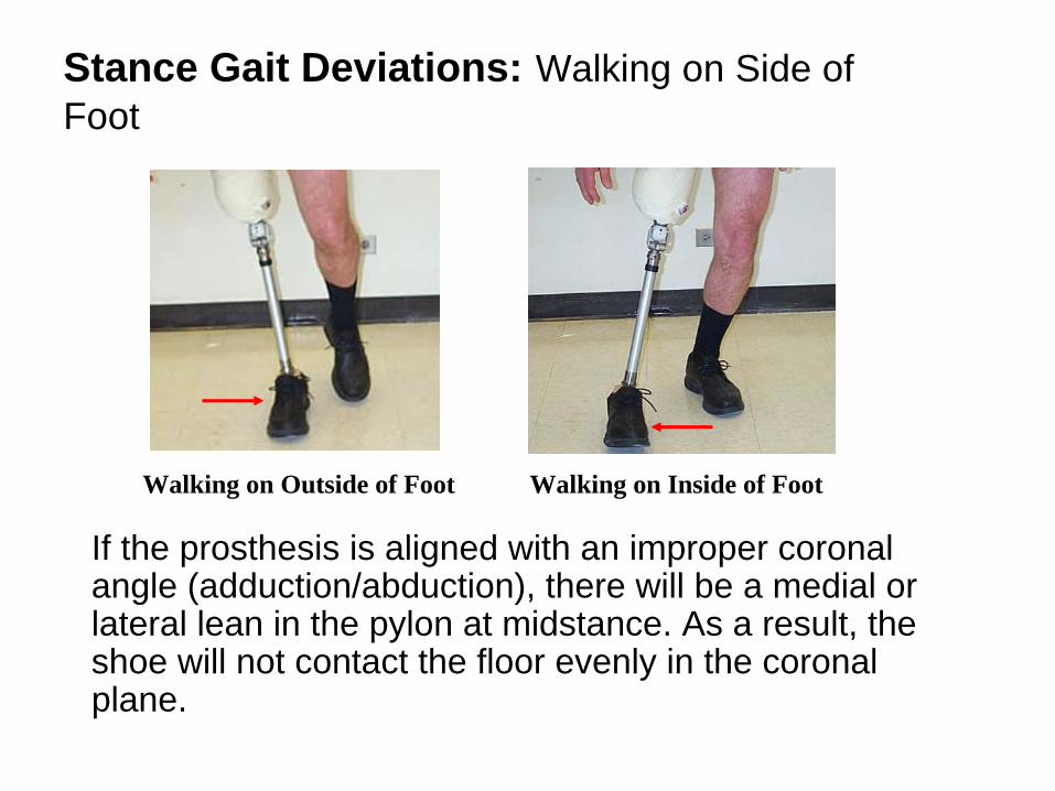
Stance Gait Deviations: Walking on Side of Foot
If the prosthesis is aligned with an improper coronal angle (adduction/abduction), there will be a medial or lateral lean in the pylon at midstance. As a result, the shoe will not contact the floor evenly in the coronal plane.
Walking on Inside of FootWalking on Outside of Foot

Stance Gait Deviations: Walking on Side of Foot
If there is a lateral lean (meaning the top of the pylon leans laterally), the person will walk on the outer border of the sole. With a medial lean (meaning the top of the pylon is leaning medially), the person will walk on the inner surface of the sole. If the lean is severe, the person will experience discomfort and feel unstable.
Correct the lean immediately upon observation by making an angular change in the coronal plane.

Stance Gait Deviations: Lateral Trunk Bending
Lateral trunk bending is characterized by excessive bending of the body laterally toward the affected side. This is a very common gait defect and gait pattern of the transfemoral amputee.
Lateral Trunk Bending

Stance Gait Deviations: Lateral Trunk Bending
Prosthetic causes of lateral trunk bending include the following:
• Pressure on the pubic ramus bone or on adductor tissue (causing the person to lean away from the prosthesis to avoid pain).
• Inadequate support of the femur through medial lateral (ML) stability
• A prosthesis that is too short (but the length would have to be really short to appear in this manner!)

Stance Gait Deviations: Lateral Trunk Bending
Amputee causes of lateral trunk bending include the following:
• A short residual limb may fail to provide a sufficient lever arm for stability
• Weak gluteus medius muscle• Inadequate balance• Habit pattern

Stance Gait Deviations: Abducted Gait
An abducted gait is characterized by a very wide base of support, with the amputee holding the prosthesis away from the midline at all times.
Abducted Gait

Stance Gait Deviations: Abducted Gait
Prosthetic Side
Midline
Sound Side
Abducted Gait

Stance Gait Deviations: Abducted Gait
Prosthetic causes of an abducted gait include the following:
• An improperly shaped medial wall, which may cause the amputee to react this way to avoid pain or discomfort
• Improper ML support built into the prosthesis; for example, a pelvic band may be positioned too far away from the body
• A prosthesis that is too long
• Excessive stability in the knee, which makes it difficult for the person to bend without fear of instability

Stance Gait Deviations: Abducted Gait
Amputee causes of an abducted gait include the following:
• Habit pattern
• Fear of bending the knee due to perceived lack of stability

Swing Gait Deviations: Vaulting
Vaulting is characterized by the person rising on the toe of the contralateral foot, which allows him to swing the prosthesis through with little or no knee flexion.
Vaulting

Swing Gait Deviations: Vaulting
Prosthetic causes of vaulting include the following:
• A prosthesis that is too long
• Inadequate suspension
Amputee causes of vaulting include the following:
• Fear of falling or stubbing the toe
• Habit pattern

Swing Gait Deviations: Uneven Heel Rise
Uneven heel rise is characterized by the prosthetic heel rising quite markedly and rapidly when the knee is flexed at the beginning of swing phase.
Uneven Heel Rise

Swing Gait Deviations: Uneven Heel Rise
Prosthetic causes of uneven heal rise include the following:
• Insufficient friction or flexion resistance in the prosthetic knee joint• Inadequate extension aid
The primary amputee cause of uneven heel rise is that the amputee is using more power than necessary to force the knee into flexion.

Swing Gait Deviations: Toe Drag
Toe drag is the dragging of the prosthetic foot on the floor during swing.
Toe Drag
Swing Gait Deviations: Toe Drag
Prosthetic causes of toe drag include the following:
• A prosthesis that is too long• The prosthetic foot is aligned with too much plantar flexion• Excessive knee friction• Inadequate suspension

Swing Gait Deviations: Terminal Impact
Terminal impact is characterized by rapid forward movement of the shank, causing the knee to reach maximum extension with too much force before heel contact. This defect is often audible.
Terminal Impact

Swing Gait Deviations: Terminal Impact
Prosthetic causes of terminal impact include the following:
• Insufficient knee friction or flexion resistance• A knee extension assist that is too powerful
The primary amputee cause of terminal impact is that the amputee is using more power than necessary to force the knee into full extension by deliberately and forcefully extending his residual limb. Some individuals like the security of ensuring the knee is in full extension before placing weight on the prosthesis for the next step.

Swing Gait Deviations: Whips
Whips occur during swing phase at the point when the prosthetic foot loses contact with the floor. A medial or lateral whip may present itself if the prosthetic knee rotation is incorrect.

Swing Gait Deviations: Medial Whip
A medial whip occurs when the prosthetic foot moves medially on initial knee flexion at early swing. A medial whip is easiest to recognize when the amputee is walking away from the observer.
Medial Whip

Swing Gait Deviations: Medial Whip
Prosthetic causes of medial whip include the following:
• Too much external rotation of the knee joint axis• Socket tightness, which may cause rotation

Swing Gait Deviations: Lateral Whip
A lateral whip occurs when the heel of the prosthetic foot moves laterally on initial knee flexion at early swing. A lateral whip is easiest to recognize when the amputee is walking away from the observer.
Lateral Whip

Swing Gait Deviations: Lateral Whip
Prosthetic causes of lateral whip include the following:
• Too much internal rotation of the knee joint axis• Socket tightness, which may cause rotation

Swing Gait Deviations: Circumducted Gait
A circumducted gait occurs when the amputee swings the prosthesis away from the midline early in swing then brings it toward the midline late in swing.
Circumducted Gait

Swing Gait Deviations: Circumducted Gait
Prosthetic Side
Midline
Sound Side
Circumducted Gait
A circumducted gait may be distinguished from an abducted gait in that it occurs only during swing phase.

Swing Gait Deviations: Circumducted Gait
Prosthetic causes of circumducted gait include the following:
• Too much stability built into the prosthesis, making it difficult for the person to flex the prosthetic knee• Too much knee friction• Too strong of an extension assist

Swing Gait Deviations: Circumducted Gait
Amputee causes of circumducted gait include the following:
• Lack the confidence for flexing the prosthetic knee due to fear of falling, stubbing his toe, or muscle weakness• Habit pattern