Embed Size (px)
Citation preview

l NSTRUCTION BOOK
MODEL 63H
INDUCTANCE BRIDGE
5 kHz to 500 kHz
BOONTON TEL: 201 -8$7-5110 TWX: 7"8-986-8241
ELEaRBNBCS ROUTE 287 AT SM~TH ROAD
c > ~ W P C > R A % B O W PARSIPPANV, N. 4.- 67054
TSHOPINSTRUCTION BOOK
MODEL 63H
INDUCTANCE BRIDGE
5 kHz to 500 kHz
1-69
TEL: 201-887-5110TWX; 710-986-8241
ROUTE 287 AT SMITH ROAD
PARSIPPANY, N .J,- 07054

TABLE OF CONTENTS
Section 1 . Specifications
Section 11 . General Description
2- 1 General ........................................... 2-1
2- 2 Bridge Circuit ..................................... 2-1
2-3 Nul l Detector ..................................... 2-3
2-4 Test Signal Oscillator .............................. 2-4
Section 1 1 1 . Operating Procedure 3-1
........................................... 3-1 Geneml 3-1
................................ 3-2 Turn-On Procedure 3-1
3 -3 Measurement Procedure ............................. 3-1
3 -4 Ac Test Voltage and Current Measurements ............. 3-10
............. 3-5 Application of Superimposed Direct Current 3.11
................... 3-6 Inductance Standardizing Technique 3-12
Section 1 V . Maintenance 4- 1
.................................... 4- 1 Circuit Checks 4-1
.............................. 4-2 Voltage Measurements 4-1
4-3 Calibration and Adjustment of Oscillator and Tuned ........................................ Detector 4-4
4-4 Bridge Section Adjustments .......................... 4-5
LIST OF FIGURES. TABLES. AND CHARTS
Figure 1 . Figure 2 . Figure 3 . Table 1 . Table 2 . Chart 1 . Chart 2 . Chart 3 . Chart 4 . Chart 5 .
................. Simplified Diagram of the Model 63H 2-2
Range of Inductance Measurement vs . Frequency ....... 2-2
................ Circuit for Applying Superimposed DC 3-12
Multiply L/R Setting for Various Ranges of .......................... Inductance Measurement 3-2
.................. Maximum Dc Current for each Range 3-11
Maximum Ac Test Current. XO.OO1 Range ............. 3-5
.............. Maximum Ac Test Current. XO.O1 Range 3-6
................ Maximum Ac Test Current. XO.l Range 3-7
................. Maximum Ac Test Current. X1 Range 3-8
................ Maximum Ac Test Current. XI0 Range 3-9
...................... ... Table of Replaceable Parts .. PL-1
TABLE OF CONTENTS
Section 1 Specifications 1-1
Secti on 11 - Genera I Descri pti on 2-1
2-1 General 2-1
2-2 Bridge Circuit 2-1
2-3 Null Detee tor 0 ••••• 0 • • • • • •• 2-3
2-4 Test Signal Oscillator •.•••.••••.•..•.••••••••••••.• 2-4
Section 111 - Operating Procedure 3-1
3-1 General 3-1
3-2 Turn-On Procedure ...•.............. 0............. 3-1
3-3 Measurement Procedure •••••.••.••..••••••.•.•.••••. 3-1
3-4 Ac Test Vol tage and Current Measurements .••••••••.•.• 3-10
3-5 Appl ication of Superi mposed Di rect Current •..••.••••.•• 3-11
3-6 Inductance Standardizing Technique •••.••.••••.••••••• 3-12
Section 1V - Maintenance 4-1
4-1 CircuitChecks .................•.•............... o 4-1
4-2 Voltage Measurements... •• . •• •• • •. •• •• .• •. • ••• •• . •• 4-1
4-3 Cal ibration and Adjustment of Osci lIator and TunedDetector .. 0 ••••••••••••••••• 0 •••••••••••••••••• 0 4-4
4-4 Bridge Section Adjustments ••••..•••......•••.••.••• 0 4-5
LIST OF FIGURES, TABLES, AND CHARTS
Figure 1•
Figure 2.
Figure 3.
Table 1 •
Table 2.
Chart 1 •
Chart 2.
Chart 3.
Chart 4.
Chart 5.
63H0-169
Simplified Diagram of the Model 63H • ••• . • . •. • •••• • .• 2-2
Range of Inductance Measurement ys. Frequency....... 2-2
Circuit for Applying Superimposed DC. • • • . • •• • • • • . • •• 3-12
Multiply L/R Setting for Various Ranges ofInductance Measurement... • • •• • • • • • • • • • . • . . • ••••• 3-2
Maximum Dc Current for each Range ••...•..•..•••.••• 3-11
Maximum J:.c Test Current, XO.OOl Range ••••.••• 0 •••• 3-5
Maximum Ac Test Current, XO.Ol Range •••..••• 0 ••••• 3-6
Maximum Ac Test Current, XO.l Range •••.•••••.•••••. 3-7
Maxi mum Ac Test Current, Xl Range ••••••••.••.••••• 3-8
Maxi mum Ac Test Current, Xl0 Range •••...••.•••...• 3-9
Table of Replaceable Parts ••••••.••••.•••• 0 •• 0 ••• 0 ••• PL-l
-1-

SECTION 1
SPEC1 FlCATlONS
Inductance Measuring Range : 0.0002 pH to 110 mH i n 5 steps as follows:
Resolution of Multiplier . Inductance Range Inductance Reading
Inductance Measuring Accuracy: (0.25% + 300/C)% + 0.0002 pH
Where,
C i s the resonating capacitance in pF of the
test inductor a t the frecpency of test.
Series Resistance Measuring Range: 0.0002 ohm to 11 K ohms in 5 ranges as follows:
Series Resistance Multiplier Range Accuracy
Frequency Range:
Frequency Accuracy:
Frequency Stability:
5 kHz to 500 kHz with internal oscillator and detector.
+ 3% - NOTE :
The accuracy of the test frequency has negligible effect on the accuracy of the inductance measurement . Approximately 0.5% after 30 minute warm-up.
Inductance Measuring Range:
SECTION 1
SPECIFICATIONS
0.0002 IJH to 11 0 mH in 5 steps as follows:
Multiplier
10.01.00.10.010.001
Inductance Range
o to 110 mHo to 11 mHo to 1100 IJHo to 110 IJHo to 11 IJH
Resol uti on ofInductance Reading
0.01% + 2.0 IJH0.01% + 0.2 IJH0.01% + 0.02 IJH0.01% + 0.002 IJH0.01% + 0.0002 IJH
Inductance Measuring Accuracy:
Series Resistance Measuring Range:
(0.25% + 300/C)% + 0.0002 IJH
Where,
C is the resonating capacitance in pF of the
test inductor at the freqJency of test.
0.0002 ohm to 11 K ohms in 5 ranges as follows:
Multiplier
10.01.00.10.010.001
Series ResistanceRange
o to 11 K Qo to 1100 Qo to 110 Qo to 11 Qo to 1.1 Q
Accuracy
3% + 0/25% + 5.0 Q3% + Q/25% + 0.5 Q3% + 0/25% + 0.05 Q3% + 0/25% + 0.005 Q3% + Q/25% + 0.001 Q
Frequency Range:
Frequency Accuracy:
Frequency Stability:
63Ha-169
5 kHz to 500 kHz with internal osci Ilatorand detector.
±3%
NOTE:
The accuracy of the test frequency hasnegligible effect on the accuracy of theinductance measurement.
Approximately 0.5% after 30 minute warm-up.
1-1

- Maximum AC Test Level:
Tube Complement:
Quantity
1 1 1 2 1 2 -
2 1 1
Power Requi rernents:
Size:
d
Mounting:
Weight:
Approximately 3. OV, rrns, open circuit .
Used In
Oscillator Pre-Ampli fier Tuned Amplifier Amplifier Rectifier Voltage Regulator Emitter-Fol Iower Emitter-Fol Iower Emi tter-Fol Iower
1 05 to 1 25V, 50-60 Hz, 60 watts, or 21 0
to 250V, 50-60 Hz as specified.
19-1/4" w x 10-3/4" h x 11-1/4" d;
case mounted.
Case mounting i s standard. Also available
for 19-inch rack mounting.
Approxi ma tel y 35 I b .
Maximum AC Test Level:
Tube Complement:
Quantity
111212211
Type
12AT76AK56U86AU66BW4OA22N404A2N1605A2N1046
Approximately 3.0V, rms, open circuit.
Used In
OscillatorPre-AmplifierTuned AmplifierAmplifierRectifierVoltage RegulatorEmitter-FollowerEmi tter- FollowerEmitter-Follower
Power Requirements:
Size:
Mounting:
Weight:
63H0-169
105 to 125V, 50-60 Hz, 60 watts, or 210
to 250V, 50-60 Hz as specified.
19-1/4" w x 10-3/4" h x 11-1/4" d;
case mounted.
Case mounting is standard. Also available
for 19-inch rack mounting.
Approximately 35 lb.
1-2

SECTION 11
GENERAL DESCRIPTION
2-1 GENERAL
2-1-1 TheModel63Hisahighlyadvancedbridgewhichprovidesdirectreading
measurements of series inductance down to low values with fractional percentage accuracy,
and under an unusually broad range of test conditions. The instrument also provides direct
reading measurement of series resistance. The operational range of the Model 63H i s shown
in the diagram on page 2-2. Inductance and resistance ranges are covered in five steps;
the frequency range i s covered in two decades.
2-1 -2 The instrument i s completely self-contained, including bridge circuitry,
variable frequency test oscillator and detector, null indicator, and power supplies. I t i s
packaged as a single, compact bench cabinet. The Model 63H may be installed in a standard
relay rack when the cabinet i s removed.
2-2 BRIDGE CIRCUIT
2-2-1 The Model 63H embodies a modified Maxwell circuit (see simplified schematic
on page 2-2). The test signal generator and null detection circuit are coupled to the bridge
by a technique which constitutes a particularly practical approach to the design of a
Maxwell bridge capable of precision measurements over wide ranges of inductance and test
frequencies. The two sides of the bridge are driven 180 degrees out of phase by a well balanced
low impedance transformer. This permits detection of the balance condition by coupling the
detector to the high corners of the bridge through two small, carefully balanced capacitors.
2-2-2 I t i s characteristic of this bridge circuit that the inductance and resistance
arms act independently of each other. By eliminating interaction between the two arms, the
annoyance and ambiguity of false or sliding nulls i s avoided.
2-2-3 Since the bridge i s of the non-resonant type, the precision of frequency
setting i s not crit ical to the accuracy of measurement. Bridge accuracy i s determined
primarily by the balancing controls, the precision resistors i n the range selector, plus the
SECTION 11
GENERAL DESCRIPTION
2-1 GENERAL
2-1-1 The Model 63H is a highly advanced bridge which provides direct reading
measurements of series inductance down to low values with fractional percentage accuracy,
and under an unusually broad range of test conditions. The instrument also provides direct
reading measurement of series resistance. The operational range of the Model 63H is shown
in the diagram on page 2-2. Inductance and resistance ranges are covered in five steps;
the freq uency range is covered in two decades.
2-1-2 The instrument is completely self-contained, including bridge circuitry,
variable frequency test oscillator and detector, null indicator, and power supplies. It is
packaged as a single, compact bench cabinet. The Model 63H may be installed in a standard
relay rack when the cabinet is removed.
2-2 BRIDGE CIRCUIT
2-2-1 The Model 63H embodies a modified Maxwell circuit (see simplified schematic
on page 2-2). The test signal generator and null detection circuit are coupled to the bridge
by a technique which constitutes a particularly practical approach to the design of a
Maxwell bridge capable of precision measurements over wide ranges of inductance and test
frequencies. The two sides of the bridge are driven 180 degrees out of phase by a well balanced
low impedance transformer. This permits detection of the balance condition by coupling the
detector to the high corners of the bridge through two small, carefully balanced capacitors.
2-2-2 It is characteristic of this bridge circuit that the inductance and resistance
arms act independently of each other. By eliminating interaction between the two arms, the
annoyance and ambiguity of false or sliding nulls is avoided.
2-2-3 Since the bridge is of the non-resonant type, the precision of frequency
setting is not critical to the accuracy of measurement. Bridge accuracy is determined
primarily by the balancing controls, the precision resistors in the range selector, plus the
63Ha-169
2-1

VAR OSC. w ~ O S C . L E V E L -
4
Figure 1 . Simplified Diagram of the Model 63H
Figure 2. Range of Inductance Measurement vs. Frequency
AC OUTPUT
1
Figure 1• Simplified Diagram of the Model 63H
X.OOI
000so 100 ZOoKILOCltU5
'0.0001 '---~-"'---"-......."--'-----'-----'
•
~
2
Ii 1 I--P'::<'''------t----t---7<El----1
10POO
Figure 2. Range of Inductance Measurement vs. Frequency
63H 2-2a-169

silvered mica and variable air capacitors comprising the inductance decades. A l l of
these components are adjusted to better than 0.1% accuracy.
2-2-4 Great care has been taken i n both the electrical and mechanical design
of the Model 63H to compensate or eliminate the sources of residual error that commonly
restrict the accuracy of measurement of bridges operating at these frequencies.
2-2-5 The excel lent scale readability of the Model 63H allows full advantage
to be taken of the instrument's capability for high precision and resolution. The
combination of the outer "counter dial" and inner 20-to-1 vernier displays the total
inductance measuring range across a scale effectively more than 200 inches long. This
dial arrangement also assures convenient rapid scanning to locate the null, as well as
accurate final adjustment.
2-3 NULL DETECTOR
2-3-1 As shown in the simplified schematic diagram on page 2-2,the nu1 l
detector i s coupled to the bridge at the high corners through two balanced capacitors.
The untuned high impedance preamp1 i fier prevents bridge loading and contributes to the
overall system sensitivity. Adjustment of the tuned detector i s independent of the test
signal generator control so that the amplifier may be crit ically tuned without altering the
test frequency.
2-3-2 Frequency response of the final wide band detector amplifier i s essentially
flat over the total frequency range of the instrument. I t has a maximum gain of 65 dB
for a total detector system gain of approximately 105 dB.
2-3-3 Output from the wide band amplifier i s passed through a half-wave
detector, compressed, and then metered. System sensitivity i s further enhanced by use
of a 50 microampere taut band meter for null indication.
2-3-4 The ac component of the rectified output from the wide band amplifier
i s also available at a rear jack for connection of an oscilloscope or other remote
indicator.
silvered mica and variable air capacitors comprising the inductance decades. All of
these components are adj usted to better than O. 1% accuracy.
2-2-4 Great care has been taken in both the electrical and mechanical design
of the Model 63H to compensate or eliminate the sources of residual error that commonly
restri ct the accuracy of measurement of bri dges operati ng at these frequenc ies.
2-2-5 The excellent scale readability of the Model 63H allows full advantage
to be taken of the instrument's capability for high precision and resolution. The
combination of the outer "counter dial" and inner 2O-to-:-1 vernier displays the total
inductance measuring range across a scale effectively more than 200 inches long. This
dial arrangement also assures convenient rapid scanning to locate the null, as well as
accurate final adjustment.
2-3 NULL DETECTOR
2-3-1 As shown in the simplified schematic diagram on page 2-2,the null
detector is coupled to the bridge at the high corners through two balanced capacitors.
The untuned high impedance preamplifier prevents bridge loading and contributes to the
overall system sensitivity. Adjustment of the tuned detector is independent of the test
signal generator control so that the amplifier may be critically tuned without altering the
test frequency.
2-3-2 Frequency response of the final wide band detector amplifier is essentially
flat over the total frequency range of the instrument. It has a maximum gain of 65 dB
for a total detector system gain of approximately 105 dB.
2-3-3 Output from the wide band amplifier is passed through a half-wave
detector, compressed, and then metered. System sensitivity is further enhanced by use
of a 50 microampere taut band meter for null indication.
2-3-4 The ac component of the rectified output from the wide band amplifier
is also available at a rear jack for connection of an oscilloscope or other remote
indicator.
63Ha-169
2-3

2-4 TEST SIGNAL OSCILLATOR
2-4-1 The internal test signal oscillator i s continuously adjustable in frequency
from 5 kHz to 500 kHz. Accuracy of frequency setting i s 3%. As stated above, in this
bridge circuit precision of test frequency setting i s not directly related to the accuracy of
measurement. However, in the rare circumstance in which more accurate frequency
adjustment i s required, the test signal may be monitored with a counter and set more precisely.
Stability of the test frequency i s better than 0.5%.
2-4-2 The test signal level i s continuously adjustable by means of a front panel
control and may be monitored at the test terminals with a high impedance electronic
voltmeter. Maximum open circuit level i s 3 volts. Test current may also be monitored by
means of a "clamp-on" type probe and a sensitive ac voltmeter. (See Paragraph 3-4-4)
2-4-3 The test current i s independent of the balance condition of the bridge, a
fact of considerable importance in applications involving such components as ferrite cores,
since their permeability varies with the level of excitation current. Were the test current
to change from the known level during balancing, meaningful measurements would be impossible.
, 2-4-4 A direct current may be superimposed on the test signal i f desired. However,
since the dc also flows through the bridge circuit, the maximum levels indicated for each
range in Table 2 on page 3-1 1 should not be exceeded. This prevents exceeding the power
dissipation l imits of the bridge components.
NOTE:
Models having serial numbers 634 or higher are equipped with
a dual-primary power transformer that i s wired either for 117V
ac or for 234V ac operation. The dual-primary transformer
replaces two power transformers (T201 and T202) used in earlier
models. A 0.6A fuse i s supplied when the transformer i s
wired for 234V ac operation, and a 1 ..2A fuse i s supplied when-
the transformer i s wired for 1 17V ac operation.
2-4 TEST SIGNAL OSCILLATOR
2-4-1 The internal test signal oscillator is continuously adjustable in frequency
from 5 kHz to 500 kHz. Accuracy of frequency setting is 3%. As stated above, in this
bridge circuit precision of test frequency setting is not directly related to the accuracy of
measurement. However, in the rare circumstance in which more accurate frequency
adjustment is required, the test signal may be monitored with a counter and set more precisely.
Stability of the test frequency is better than 005%.
2-4-2 The test signal level is continuously adjustable by means of a front panel
control and may be monitored at the test terminals with a high impedance electronic
voltmeter. Maximum open circuit level is 3 volts. Test current may also be monitored by
means of a "clamp-on" type probe and a sensitive ac voltmeter. (See Paragraph 3-4-4)
2-4-3 The test current is independent of the balance condition of the bridge, a
fact of considerable importance in applications involving such components as ferrite cores,
since their permeability varies with the level of excitation current. Were the test current
to change from the known level during balancing, meaningful measurements would be impossible.
2-4-4 A direct current may be superimposed on the test signal if desired 0 However,
since the dc also flows through the bridge circuit, the maximum levels indicated for each
range in Tabl e 2 on page 3-11 shou Id not be exceeded 0 Th is prevents exceedi ng the power
dissipation Iimits of the bridge components.
NOTE:
Models having serial numbers 634 or higher are equipped with
a dual-primary power transformer that is wired either for 117V
ac or for 234V ac operation. The dual-primary transformer
replaces two power transformers (T201 and T202) used in earlier
models. A 0.6A fuse is supplied when the transformer is
wired for 234V ac operatie>n, and a 1 .2A fuse is supplied when
the transformer is wired for 117V ac operati on •
./
63Ha-169
2-4

SECTION 11 1
OPERATI NG PROCEDURE
3-1 GENERAL
3-1 -1 This section describes in detail the operating procedure of the Model 63H
Inductance Bridge. A l l information required for safe and proper operation of the instrument
i s included. BE SURE TO READ THIS SECTION BEFORE PLACING THE INSTRUMENT INTO ----- - OPERATION.
3-2 TURN-ON PROCEDURE
Step a. Before plugging the instrument into an appropriate - outlet, make sure the power source i s 1 05-1 25 volts,
50-60 Hz, unless otherwise specified on the
instrument's identification plate.
Stepb. - Plugtheinstrumentintothepoweroutlet.
Step c. Set toggle switch to ON and allow a warm-up period - of approximately two minutes (one hour or more
after high humidity exposure or after long exposure
to low temperature) .
3-3 MEASUREMENT PROCEDURE
Step - a. Connect the short circuit plug (or strap) supplied with
the instrument across the TEST binding posts.
PRECAUTION
When using the XO.OO1 position of the MULTIPLY L
AND R BY switch, the shorting l ink supplied with
the bridge must be used for zeroing the bridge; on
a l l other ranges the shorting plug may be used. I f - the shorting plug i s used for the XO.OO1 range i t
may not be possible to zero the bridge.
3-1 GENERAL
SECTION 111
OPERA TI NG PROCEDURE
3-1-1 This section describes in detai I the operating procedure of the Model 63H
Inductance Bridge. All information required for safe and proper operation of the instrument
is included. BE SURE TO READ THIS SECTION BEFORE PLACING THE INSTRUMENT INTO--- - ----OPERATION.
3-2 TURN-ON PROCEDURE
Step ~.
Step!: •
Step ~.
Before plugging the instrument into an appropriate
outlet, make sure the power source is 105-125 volts,
50-60 Hz, unless otherwise specified on the
instrument's identification plate.
Plug the instrument into the power outlet.
Set toggle switch to ON and allow a warm-up period
of approximately two minutes (one hour or more
after high humidity exposure or after long exposure
to low temperature).
3-3 MEASUREMENT PROCEDURE
63H0-169
Step ~. Connect the short circuit plug (or strap) supplied with
the instrument across the TEST binding posts.
PRECAUTION
When using the XO.OOl position of the MULTIPLY L
AND R BY switch, the shorting link supplied with
. ~he bridge must be used for zeroing the bric;!ge; on
all other ranges the shorting plug may be used. If
the shorting plug is used for the XO.OOl range it
may not be possible to zero the bridge.
3-1

Step b. Set oscillator range switch to either X1 or XI 0 - position, depending upon the required test
frequency. Use XI i f frequency i s below 50 kHz;
otherwise use XI 0 ~ o s i tion.
NOTE:
This "Range Selector" also selects desired range
for the Tuned Detector. Refer to page 2-2 to
determine that both frequency and inductance
fa1 l within boundary area shown. For greater
accuracy, refer to accuracy statement on
page 1-1.
Step - c. Set MULTIPLY L AND R BY switch to range
recommended i n table for inductance under test.
(See Table 1 below)
Table 1
r t
I MULTIPLY I NDUCTANCE i L AND R BY
0.0 to 11 pH 0.001 ,
11.0 to 110 pH 1 I 0.01 i
110.0 to l l 0 0 p H ' I 0.1
1 .l to 11 mH j 1 .o 11 .O to 110 mH - 1 10.0
1 I
Step - d. Set both SERIES INDUCTANCE dials to read zero and
both SERIES RESISTANCE dials to read zero.
Step - e. Set OSC LEVEL control to the "RED LINE" position.
Step ~. Set osci "ator range swi tch to ei ther Xl or Xl0
position, depending upon the required test
frequency. UJ,; Xl if frequency is below 50 kHz;
otherwise use Xl0 position.
NOTE:
This "Range Selector" also selects desired range
for the Tuned Detector. Refer to page 2-2 to
determine that both frequency and inductance
fall within boundary area shown. For greater
accuracy, refer to accuracy statement on
page 1-1 •
Step ~. Set MUL T1PLY LAND R BY switch to range
recommended in table for inductance under test.
(See Table 1 below)
Table 1
INDUCTANCE
0.0 to 11 fJH
11 .0 to 110 'fJH
110 •0 to 1100 fJ H
1•1 to 11 mH
11 .0 to 11 0 mH
It 0
,,,,,
MULTIPLYLAND R BY
0.001
0.01
0.1
1.0
10.0
/
63Ha-169
Step ~. Set both SERIES INDUCTANCE dials to read zero and
both SERIES RESISTANCE dials to read zero.
Step~. Set OSC LEVEL control to the "RED L1NE" position.
3-2
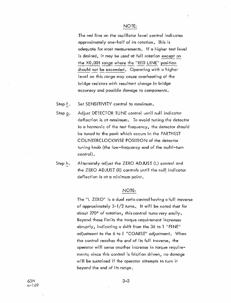
NOTE:
The red line on the oscillator level control indicates
approximately one-half of its rotation. This i s
adequate for most measurements. I f a higher test level
i s desired, i t may be used at full rotation except on -- the XO.OO1 range where the "RED LINE" position
should not be exceeded. Operating with a higher --- level on this range may cause overheating of the
bridge resistors with resultant change in bridge
accuracy and possible damage to components.
Step f . Set SENSITIVITY control to maximum. - Step g . Adjust DETECTOR TUNE control until null indicator -
deflection i s at maximum. To avoid tuning the detector
to a harmonic of the test frequency, the detector should
be tuned to the peak which occurs i n the FARTHEST
COUNTERCLOCKWISE POSITION of the detector
tuning knob (the low-frequency end of the multi-turn
control).
Step - h. Alternately adjust the ZERO ADJUST (L) control and
the ZERO ADJUST (R) controls until the null, indicator
deflection i s at a minimum point.
NOTE:
The " L ZERO" i s a dual ratio control having a ful l traverse
of approximately 3-1/2 turns. It w i l l be noted that for
about 270° of rotation, this control turns very easily . Beyond these limits the torque requirement increases
abruptly, indicating a shift from the 36 to 1 "FINE"
adjustment to the 6 to 1 "COARSE" adjustment. When
the control reaches the end of its full traverse, the
opera tor wi I I sense another increase in torque require-
ments; since this control i s friction driven, no damage
w i l l be sustained i f the operator attempts to turn it
beyond the end of its range.
63Ha-169
Step £.. 0
Step ,go
Step ~ 0
NOTE:
The red line on the oscillator level control indicates
approximately one-half of its rotation. This is
adequate for most measurements. If a higher test level
is desired, it may be used at full rotation except on
the XO.OOl range where the" RED LI NE" position
should not be exceeded. Operating with a higher
level on this range may cause overheating of the
bridge resistors with resultant change in bridge
aC,curacy and possible damage to components.
Set SENSITIVITY control to maximum.
Adjust DETECTOR TUNE control until null indicator
deflection is at maximum. To avoid tuning the detector
to a harmonic of the test frequency, the detector should
be tuned to the peak which occurs in the FARTHEST
COUNTERCLOCKWISE POSITION of the detector
tuning knob (the low-frequency end of the multi-turn
control) •
Alternately adjust the ZERO ADJUST (L) control and
the ZERO ADJUST (R) controls until the nuq indicator
deflection is at a minimum point 0
NOTE:
The "L ZERO" is a dual ratio control having a full traverse
of approximately 3-1/2 turns. It will be noted that for
about 270 0 of rotation, this control turns very easily.
Beyond these limits the torque requirement increases
abruptly, indicating a shift from the 36 to 1 "FINE"
adjustment to the 6 to 1 "COARSE" adjustment. When
the control reaches the end of its full traverse, the
operator will sense another increase in torque require
ments; since this control is friction driven, no damage
will be sustained if the operator attempts to turn it
beyond the end of its range.
3-3

The " R ZERO" adjustment consists of two separate
controls; "COARSE" for rapid scanning, and "FINE"
for precise adjustment in locating the null.
Step - i . After obtaining minimum deflection of the null indicator,
i t i s usually desirable to adjust the sensitivity control
to reduce the residual noise level. Leaving al l other
controls undisturbed, adjust the sensitivity control
unti l a reading of one and one-half (1 -1/2) meter
divisions i s obtained. This sensitivity level i s
adequate for the vast majority of applications. I t
minimizes the effects of the total system noise;
in addition, experience has show;? that i t i s more
convenient to locate a nu1 l with low meter readings
rather than at half scale or above.
Step i . Remove the short circuit from across the TEST binding - posts and connect the test specimen.
Step - k. Adjust the SERIES I NDUCTANCE "1 000 pH" decade
switch for minimum deflection of the nu1 l indicator.
Adjust the MICROHENRIES dial to obtain a lower null
indication. I f null deflection i s not reduced, then
set this decade switch to next lower position and
readjust MICROHENRIES dial for minimum deflection.
Step - I . Now adjust the SERIES RESISTANCE control for further
reduction of null indication. Use "100 S2" decade switch
i f necessary.
Step - m. Now alternately adjust the SERIES INDUCTANCE and
SERIES RESISTANCE controls until null indicator
deflection i s an absolute minimum.
Step - n. To obtain the value of inductance under test, add the
readings on the two SERIES INDUCTANCE dials and
multiply by the factor indicated on the MULTIPLY L
AND R BY dial.
Step .!-.
Step 1.
Step ~.
Step ~.
The" R ZERO" adjustment consists of two separate
controls; "COARSE II for rapid scanning, and II FI NEil
for precise adjustment in locating the null.
After obtaining minimum deflection of the null indicator,
it is usually desirable to adjust the sensitivity control
to reduce the residual noise level. Leaving all other
controls undisturbed, adjust the sensitivity control
until a reading of one and one-half (1-1/2) meter
divisions is obtained. This sensitivity level is
adequate for the vast majority of applications. It
minimizes the effects of the total system noise;
in addition, experience has shown that it is more
convenient to locate a null with low meter readings
rather than at half scale or above.
Remove the short circuit from across the TEST binding
posts and connect the test specimen.
Adjust the SERIES INDUCTANCE 111000 pHil decade
switch for minimum deflection of the null indicator.
Adjust the MICROHENRIES dial to obtain a lower null
indication. If null deflection is not reduced, then
set this decade switch to next lower position and
readjust MICROHENRIES dial for minimum deflection.
Now adjust th~:SERIES RESISTANCE control for further
reduction of null indication. Use 11100 nil decade switch
if necessary.
Step m. Now alternately adjust the SERIES INDUCTANCE and
SERIES RESISTANCE controls until null indicator
deflection is an absolute minimum.
Step~. To obtain the value of inductance under test, add the
readings on the two SERIES INDUCTANCE dials and
multiply by the factor indicated on the MULT1PLY L
AND R BY dial.
8H 3~
a-169

5 kHz 50 kHz 500 kHz
FREQUENCY kHz
l I
5 kHz 50 kHz 500 kHz
o 0- 280I W
...... I$
()c;;:0;;:0mZ-I
~l>...-...Im<mI
()
0W Z
-II ;;:001 0
I
l>-I
~
0;;:0
0>-I
0Z--
260
240
220
200
180
160
140
120
100
8()
60
40
20
o
-- ...... ...... ....---............ ~
~
'" '" 1 fJH\..
" ~"\,\,
\ 10 }JH \\ \
1\ \~
\"~
""FREQUENCY kHz
0-WI
~l>X~C~
l>()
-Imtil-I ()() :r
0C ..,;;:0 ....;;:0m'Z-I
X0.00.....;;:0
l>Z(;)m

Chart 2 63H MAXIMUM AC TEST CURRENT XO.O1 RANGE
N I Y
0 0 ul
N I Y
0 ul
N I Y
ul
0 z 0 d
0 Q -
CURRENT MA.
63 H a-1 69 3-6
Chart 2
63H MAXIMUM AC TEST CURRENT XO.Ol RANGE
>UZw::JoW0.:: 'u..
NI~
ooCD
oco
/ //
V // V
/
/;// ./
I ./
/ .// ./
./
I /I ./':J-
~/
/ I
/II
III
0 0
NI~
ool[')
NI~
ol[')
NI~
l[')
63Ha-169
CURRENT MA.
3-6

Chart 3 63H MAXIMUM AC TEST CURRENT XO.l RANGE
CURRENT MA. - -
-------------------------
Chart 363H MAXIMUM AC TEST CURRENT XO.1 RANGE
>UZw:::>ow~LL.
NI~
oco
I::J..
0 ./ /~
.,V /~V /
VI , /I!I ~
./. /V
/'/'
/V
I VE
1/
N
NI~
ofX
NI~
I.{)
63Ha-169
CURRENT MA.
3-7,

Chart 4 . --.
63H MAXIMUM AC TEST CURRENT XI RANGE
CURRENT MA.
3 -8
Chart 4. _.63H MAXIMUM AC TEST CURRENT Xl RANGE
>UZUJ:::)
oUJ~u..
NI....::£
oco
1/ // / I
3: / / I....... / V I-~/ /' I/ / I
/ ./V /
/ /' /,V V/
!/ 3: /E0r-
I 1/I ~
I /1/ 7'
V
IC'J 0
NI....::£
oo
NI....::£
ll")
NI....::£
o
/
63H0-169
. CURRENT MA.
3-8

Chart 5 6 3 ~ MAXIMUM AC TEST CURRENT XIO RANGE
N I Y
0 'n
N I Y
N > I Y
V z 0 W - 3
C, W ai U,
N I Y
'n
4 * 9 0 CU - -
"I .
CURRENT MA.
NI~
oll')
NI~
o~
NI~
ll')
Chart 563H MAXIMUM AC TEST CURRENT X10 RANGE.
1I
I
/ /1/ V I/ I II V I
I EI E 0E ;; 0
~
~
!
/ I/ 1/
1/ j
1 /I I /
. N
I~
>-~w:::>owB:
63H0-169
" ~.'
CURRENT MA.
3-9
o

Example:
Reading on 1000 pH dial = 3000.0 pH
Reading on SERIES INDUCTANCE dial = 437.5 pH
Sum = 3437.5 pH
MULTIPLY L AND R BY dial = 0.1
Inductance of coil under test = 343.75 pH
Stepo. - Toobtainthevalueofseriesresistanceundertest,
add the readings on the two SERIES RESISTANCE
dials and multiply by the factor indicated on the
MULTIPLY L AND R BY dial.
Example:
Reading on 100R dial = 0 . 0 ~
Reading on SERIES RESISTANCE dial = 64.OR
Sum = 64.00
MULTIPLY L AND R BY dial = 0.1
Resistance of coil under test = 6.4R
3-4 AC TEST VOLTAGE AND CURRENT MEASUREMENTS
3-4-1 The ac voltage across the test specimen or the alternating current passing
through the test can be adjusted from nearly zero to maximum by means of the OSC
LEVEL control. Maximum open-circuit test voltage i s approximately 3.0 volts rms on a l l
ranges except on the XO.OO1 range, where i t i s approximately 1.5 V.
3-4-2 PRECAUTION: When operating on the XO.OO1 range, the oscillator level
control should not be set beyond approximately the "RED LINE" position i n order to avoid
possible distortion of the test signal, and also to prevent heating of resistors i n the bridge
which might cause drift in null indication.
3-4-3 The voltage appearing across the test at balance can be measured by a high
impedance vacuum tube voltmeter.
Example:
Reading on 1000 tJH dial
Reading on SERIES INDUCTANCE dial
Sum
MUL TIPLY LAND R BY dial = 0.1
Inductance of coi I under test
= 3000.0 tJH
= 437.5 pH
= 3437.5 tJH
= 343.75 tJH
Step ~. To obtain the value of series resistance under test,
add the readings on the two SERIES RESISTANCE
dials and multiply by the factor indicated on the
MULTIPLY LAND R BY dial.
Example:
Reading on 1000 dial
Reading on SERIES RESISTA NCE dial
Sum
MUL TIPLY LAND R BY dial = 0.1
Resistance of coil under test
= 0.00
= 64.00
= 64.00
= 6.40
3-4 AC TEST VOLTAGE AND CURRENT MEASUREMENTS
3-4-1 The ac voltage across the test specimen or the alternating current passing
through the test can be adjusted from nearly zero to maximum by means of the OSC
LEVEL control. Maximum open-circuit test voltage is approximately 3.0 volts rms on all
ranges except on the XO.OOl range, where it is approximately 1 .5 V.
3-4-2 PRECAUTION: When operating on the XO.OOl range, the oscillator level
control should not be set beyond approximately the "RED LI NE" position in order to avoid
possible distortion of the test signal, and also to prevent heating of resistors in the bridge
which might cause drift in null indication.
3-4-3 The voltage appearing across the test at balance can be measured by a high
impedance vacuum tube voltmeter.
63Ha-169
3-10

3-4-4 The current through the test may be determined with a clip-on type
ac milliammeter. It may also be determined by measuring the voltage drop across a one
ohm resistor-connected between the GND terminal and the specimen under test. The current
in milliamperes can thus be read directly in terms of millivolts across the one ohm resistor.
However, i f the latter method i s used, the one ohm of resistance must be subtracted from the
indicated Series Resistance to obtain the correct value.
3-4-5 Maximum ac test current values versus frequency for each range are shown
in the charts on pages 3-5 to 3-9.
3-5 APPLICATION OF SUPERIMPOSED DIRECT CURRENT
3-5-1 Superimposed direct current may be applied to the coil under test within
the maximum limits indicated in the following table.
NOTE:
Values shown in this table are the maximum dc levels that may
be superimposed on the full ac level without overheating the
bridge resistors, Exceeding the value for any given range could
cause heating of the bridge resistors, with resultant nu1 l drift,
or altered bridge calibration. I f the overload i s prolonged or i s
substantial l y beyond specified limits, extensive damage to
bridge components may result.
Table 2
MULTIPLY L/R MAX. DIRECT CURRENT RANGE Mi I l iamperes
0.001 300
0.01 1 50
0.1 70
1 .O 70
10.0 50
I L
3-4-4 The current through the test may be determined with a clip-on type
ac milliammeter. It may also be determined by measuring the voltage drop across a one
ohm resistor connected between the GND terminal and the specimen under test. The current
in milliamperes can thus be read directly in terms of millivolts across the one ohm resistor.
However, if the latter method is used, the one ohm of resistance must be subtracted from the
indicated Series Resistance to obtain the correct value.
3-4-5 Maximum ac test current values versus frequency for each range are shown
in the charts on pages 3-5 to 3-9.
3-5 APPLICATION OF SUPERIMPOSED DIRECT CURRENT
3-5-1 Superimposed direct current may be applied to the coil under test within
the maximum limits indicated in the following table.
NOTE:
Values shown in this table are the maximum dc levels that may
be superimposed on the full ac level without overheating the
bridge resistors. Exceeding the value for any given range could
cause heating of the bridge resistors, with resultant null drift,
or altered bridge calibration 0 If the overload is prolonged or is
substantially beyond specified limits, extensive damage to
bri dge components may resu It.
Table 2
63Ha-169
MULTIPLY L/RRANGE
0.001
0.01
0.1
1.0
10.0
MAX. DIRECT CURRE NTMilliamperes
300
150
707050
3-11

3-5-2 The direct current source and milliammeter should be connected between
the GND binding post and the low side of the test. (See accompanying diagram). A high-
capacitance electrolytic capacitor* of adequate voltage rating should be connected across
the dc source and milliammeter to minimize errors resulting from this series impedance. This impedance may also be measured and the values subtracted from the final measurement.
* Electrolytic capacitors with high effective series resistance should not be used.
f TEST
DC DC MILLIAMMETER SOURCE
Figure3. Circuitforapplyingsuperimposeddc.
3-6 INDUCTANCE STANDARDIZING TECHNIQUE
lnductance may be standardized by a series resonant method using precision
capacitors and frequency standards. The Model 63H lnductance Bridge may be utilized
to determine the series resonant condition.
3-6-1 Connect a stable external oscillator to the bridge transformer. Adjust
the external signal source to the desired frequency using a precision electronic counter
(0.01%).
3-6-2 Select a high Q, stable, mica capacitor having a capacitance slightly
greater (not more than 5%) than that required to resonate the inductor to be standardized.
This capacitance must be greater than the required value so that the final effective
inductance w i l l read up-scale on the dial.
3-5-2 The direct current source and milliammeter should be connected between
the GND binding post and the low side of the test. (See accompanying diagram). A high
capacitance electrolytic capacitor* of adequate voltage rating should be connected across
the dc source and milliammeter to minimize errors resulting from this series impedance. This
impedance may also be measured and the values subtracted from the final measurement.
* Electrolytic capacitors with high effective series resistance should not be used.
TEST
DCMILLIAMMETER
DCSOURCE
TESTSAMPLE
Figure 3. Circuit for applying superimposed dc.
3-6 INDUCTANCE STANDARDIZING TECHNIQUE
Inductance may be standardized by a series resonant method using precision
capacitors and frequency standards. The Model 63H Inductance Bridge may be utilized
to determine the series resonant condition.
3-6-1 Connect a stable external osci Ilator to the bridge transformer. Adjust
the external signal source to the desired frequency using a precision electronic counter
(0001%).
3-6-2 Select a high Q, stable, mica capacitor having a capacitance slightly
greater (not more than 5%) than that required to resonate the inductor to be standardized.
This capacitance must be greater than the required value so that the final effective
inductance will read up-scale on the dial.
63Ha-169
3-12

3-6-3 Using a precision capacitance bridge, determine the absolute capacitance
of the standard capacitor. A BEC Model 74D 100 kHz Capacitance Bridge may be used for
this purpose. I f a frequency other than 100 kHz i s to be used for the calibration of the
standard inductor, a Model 75C may be substituted.
Determine also the shunt conductance of the capacitor. The measurement
of conductance should be made at the test frequency. This may be accomplished with a
variable frequency capacitance bridge such as the BEC Model 75C.
Calculate the equivalent series resistance of the standard capacitor using
the relationship:
Series Resistance = RC = G
w 2c2
Where
G = the shunt conductance of the capacitor in mhos,
measured at the test frequency.
C = the capacitance of the standard capacitor i n
farads
and
w = 2lTf
3-6-4 Adjust the bridge at the test frequency for zero balance ~f both L and R on
a suitable L/R range. The MULTIPLY L AND R BY switch may be set one step lower than
would normally be used to measure the inductor to obtain a better readout for resistance.
3-6-5 Connect the test inductor and standard capacitor in series across the TEST
binding post of the bridge. Connect the low side of the inductor to ground and the standard
capacitor to the high side of the coi l and test terminal of the bridge.
3-6-6 Balance the bridge and read the inductance and resistance values as well as
the exact frequency of the external oscillator.
Record the inductance reading (A L)
Record the resistance reading (R1 ) Record the frequency ( f j
3-6-3 Using a precision capacitance bridge, determine the absolute capacitance
of the standard capacitor. A BEC Model 74D 100 kHz Capacitance Bridge may be used for
this purpose. If a frequency other than 100 kHz is to be used for the calibration of the
standard inductor, a Model 75C may be substituted.
Determine also the shunt conductance of the capacitor. The measurement
of conductance should be made at the test frequency. This may be accomplished with a
variable frequency capacitance bridge such as the BEC Model 75C.
Calculate the equivalent series resistance of the standard capacitor using
the relationship:
Series Resistance = RC
= 2GW C2
Where
G = the shunt conductance of the capacitor in mhos,
measured at the test frequency.
C = the capacitance of the standard capacitor in
farads
and
c.) = 2nf
3-6-4 Adjust the bridge at the test frequency for zero balance of both Land R on
a suitable L/R range. The MULTIPLY LAND R BY switch may be set one step lower than
would normally be used to measure the inductor to obtain a better readout for resistance.
3-6-5 Connect the test inductor and standard capacitor in series across the TEST
binding post of the bridge. Connect the low side of the inductor to ground and the standard
capacitor to the high side of the coil and test terminal of the bridge.
3-6-6 Balance the bridge and read the inductance and resistance values as well as
the exact frequency of the external oscillator.
Record the inductance reading (A L)
Record the resistance readi ng (R1)
Record the frequency ( f )
63Ha-169
3-13

3-6-7 Compute the equivalent negative inductance of the standard capacitor.
True inductance of standard = L + A L
True resistance of standard = R1 - RC
3-6-8 Check the accuracy of the bridge resistance reading by substituting a decade
resistance box such as a General Radio No. 1432 across the test terminals and adjusting the
resistance box and reactive bridge controls for a null. Do not adjust the resistance dial.
3-6-9 The accuracy of this technique depends largely upon the care in measuring
the standard capacitor and frequency in Steps 3-6-3 and 3-6-6. Precautions should be
taken to avoid introducing stray capacitance across the test terminals as well as using short
leads with a minimum of contact resistance while measuring the resistance i n Step 3-6-8.
3-6-7 Compute the equivalent negative inductance of the standard capacitor.
L = 1N W 2C
True inductance of standard = LN + 6 L
True resistance of standard = R1 - RC
3-6-8 Check the accuracy of the bridge resistance reading by substituting a decade
resistance box such as a General Radio No. 1432 across the test terminals and adjusting the
resistance box and reactive bridge controls for a null. Do not adjust the resistance dial.
3-6-9 The accuracy of this technique depends largely upon the care in measuring
the standard capacitor and frequency in Steps 3-6-3 and 3-6-6. Precautions should be
taken to avoid introducing stray capacitance across the test terminals as well as using short
leads with a minimum of contact resistance while measuring the resistance in Step 3-6-8.
63Ha-169
3-14

SECTION 1 V
MA1 NTE NANCE
4-1 CIRCUIT CHECKS
The following information i s given to aid in trouble shooting the various circuits of
the bridge as well as to determine i f a l l circuits are operating properly.
Voltage measurements were made from the indicated point to chassis ground with a
multitester such as a Simpson No. 260 or equivalent. The voltages are nominal and may
vary slightly between units due to component tolerances. Vol tage measurements are made
at nominal line voltage and under full load conditions.
4-2 VOLTAGE MEASUREMENTS
4-2-1 Power Supply
V201 6BW4 - Rectifier tube voltage readings.
Pin No. 1 380V ac Pin No. 7 380V ac
Pin No. 4 6.3V ac Pin No. 9 +425V dc
Junction of L201, C202b and R202 +415V ac
Junction of D205 and D206 5.5V ac
Junction of D207 and D208 5.5V ac
Junction of D201 and D202 15 V ac
Junction of D203 and D204 15 V ac
Junction of D201, D203 and C201 -34 V ac
Voltage measurements made at the 12 pin connector, J201, are as
fol lows:
Pin No. 3 +300V dc Pin No. 7 6.3V ac
Pin No. 4 +300V dc Pin No. 8 -6.6V dc
Pin No. 5 +150V dc Pin No. 9 +6.6V dc
Pin No. 6 6.3V ac Pin No. 11 -1 1.5V dc
The total power from the ac line, with a nominal line voltage of
120 volts, should be 60 watts as measured with a Sensitive Research,
Model Univ. Wattmeter.
SECTION 1V
MAINTENANCE
4-1 CIRCUIT CHECKS
The following information is given to aid in trouble shooting the various circuits of
the bridge as well as to determine if all circuits are operating properly.
Voltage measurements were made from the indicated point to chassis ground with a
multitester such as a Simpson No. 260 or equivalent. The voltages are nominal and may
vary slightly between units due to component tolerances. Voltage measurements are made
at nominal line voltage and under full load conditions.
4-2 VOLTAGE MEASUREMENTS
4-2-1 Power Supply
V201 6BW4 - Rectifier tube voltage readings.
Pin No.1 380V ac Pin No.7
Pin No.4 6.3V ac Pin No.9
380V ac
+425V dc
63H0-169
Junction of L201, C202b and R202 +415V ac
Junction of 0205 and 0206 5.5V ac
Junction of 0207 and 0208 5.5V ac
Junction of 0201 and 0202 15 V ac
Junction of 0203 and 0204 15 V ac
Junction of 0201, 0203 and C20l -34 V ac
Voltage measurements made at the 12 pin connector, J201, are as
follows:
Pin No.3 +300V dc Pin No.7 6.3V ac
Pin No.4 +300V dc Pin No.8 -6.6V dc
Pin No.5 +150V de Pin No. 9 +6.6V de
Pin No.6 6~3V ac Pin No. 11 -11.5V dc
The total power from the ac line, with a nominal line voltage of
120 volts, should be 60 watts as measured with a Sensitive Research,
Model Univ. Wattmeter.
4-1

4-2-2 Oscillator ~- -
Osci I lator tube voltage readings Vl01 1 2AT7
Pin No. 1 +200V dc Pin No. 7 OV
Pin No. 2 OV Pin No. 8 +1.7V dc
Pin No. 3 +2.9V dc Pin No. 9 6.3V ac
Pin No. 6 +156V dc
The total current drawn by the oscillator under normal conditions
should be 7 mA.
The following are nominal ac voltages taken at the iunction of R107
and R108 with a Ballantine 314 VTVM:
XI Range: 5 kHz 6.6V 25 kHz 6.2V
10 kHz 6.4V 50kHz 6.2V
V l 0 Range: 50 kHz 6.4V 250 kHz 6.2V
100 kHz 6.4V 500 kHz 6.2V
4-2-3 Emitter Follower
The following are nominal dc voltages throughout the emitter follower
circuit. CAUTfON: In making voltage measurements i t i s absolutely necessary - notto short
the test lead to ground from any point being measured.
Q l 01 2 N404A Emi tter -21 .5 volts
Base -21 .O volts
Collector -34 volts Supply
Q102 2N404A Emitter -21.5 volts
Base -21.5 volts
Collector -34 volts Supply
Q103 2N1605 Emi tter -21.5 volts
Base -21.5 volts
Collector -18.0 volts
Q104 2 N1046 Emi tter -21 .0 volts
Base -21 .5 volts
Col lector -34 -
Supply
4-2-2 Oscillator
Oscillator tube voltage readings VlOl 12AT7
Pin No. +200V de Pin No.7
Pin No.2 OV Pin No.8
Pin No.3 +2.9V de Pin No.9
Pin No.6 +156V dc
OV
+1.7V dc
6.3V ac
The total current drawn by the oscillator under normal conditions
should be 7 mAo
The following are nominal ac voltages taken at the junction of Rl07
and Rl08 with a Ballantine 314 VTVM:
Xl Range:
Vl 0 Range:
4-2-3 Emitter Follower
5 kHz
10 kHz
50 kHz
100 kHz
6.6V
6.4V
6.4V
6.4V
25 kHz
50 kHz
250 kHz
500 kHz
6.2V
6.2V
6.2V
6.2V
The following are nominal dc voltages throughout the emitter follower
circuit. CAUnON: In making voltage measurements it is absolutely necessary notto short
the test lead to ground from any point being measured.
0101 2N404A
63Ha-169
0102
0103
Ql04
2N404A
2Nl605
2Nl046
Emitter -21 .5 volts
Base -21.0 volts
Collector -34 volts
Emitter -21.5 volts
Base -21.5 volts
Collector -34 volts
Emitter -21 .5 volts
Base -21 .5 vol ts
Collector -18.0 volts
Emitter -21 .0 vol ts
Base -21.5 volts
Collector -34
4-2
Supply
Supply
Supply

4-2-4 Tuned Detector
Tuned detector tube voltage readings. V501 6U8
Pin No. 1 +130V dc Pin No. 6 +85V dc
Pin No. 2 OV Pin No.7 +1.3V dc
Pin No. 3 + 90V dc Pin No.8 +6.2V dc
Pin No.4 +6.6V dc Pin No. 9 OV
Pin No. 5 Ground
4-2-5 Preamplifier
Preamplifier tube voltage readings. V401 6AK5
Pin No. 1 OV Pin No . 5 +21 V dc*
Pin No. 2 No pin Pin No. 6 +60V dc*
Pin No. 3 Ground Pin No.7 +1.5V dc*
Pin No. 4 +6.6V dc
* These voltages are with no signal input and wi l l vary widely with
signal input.
4-2-6 Wideband Amplifier
The following voltage readings are made with SE NSITIVl TY control at
maximum gain and no i-nput signal.
V60 1 6AU6
Pin No. 1 OV P inNo .6 +178V dc
Pin No. 4 6.3V ac Pin No. 7 +2.5V dc
Pin No. 5 +185V dc
V602 6AU6
Pin No. 1 OV
Pin No. 4 6.3V ac
P inNo .5 +208V dc
Pin No. 6 +150V dc
Pin No. 7 +4V dc
4-2-4 Tuned Detector
Tuned detector tube voltage readings.
Pin No.1 +130V de
Pin No.2 OV
Pin No.3 + 90V de
Pin No.4 +6.6V de
Pin No.5 Ground
4-2-5 Preamplifier
V501 6U8
Pin No.6
Pin No.7
Pin No.8
Pin No.9
+85V de
+1.3V de
+6.2V de
OV
Preamplifier tube voltage readings.
Pin No.1 OV
Pin No.2 No pin
Pin No.3 Ground
Pin No.4 +6.6V de
V401 6AK5
Pin No.5
Pin No. 6
Pin No.7
+21 V de*
+60V de*
+1.5V de*
* These voltages are with no signal input and will vary widely with
signal input.
4-2-6 Wideband Amplifier
The following voltage readings are made with SE NSITIVI TV control at
maximum gain and no i·nput signal.
63Ha-169
V601 6AU6
Pin No.1 OV
Pin No.4 6.3V ae
Pin No.5 +185V de
V602 6AU6
Pin No.1 OV
Pin No.4 6.3V ae
Pin No.5 +208V de
4-3
Pin No.6
Pin No.7
Pin No.6
Pin No.7
+178V de
+2.5V de
+150V de
+4V de
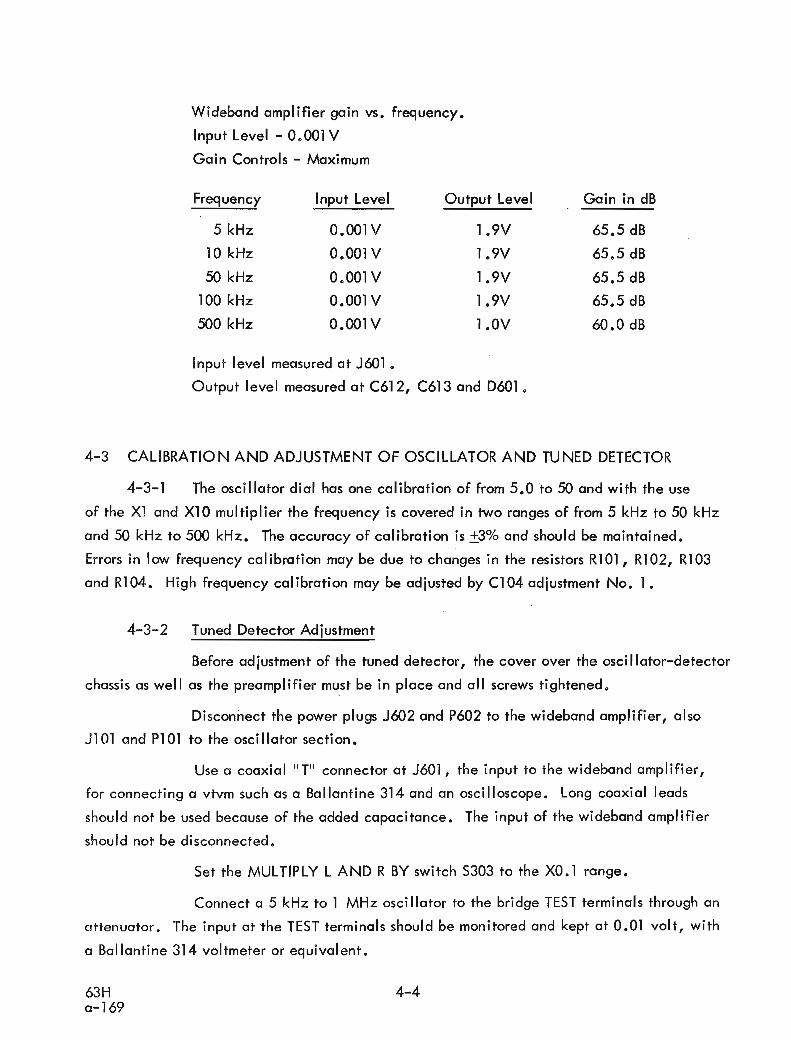
Wideband amplifier gain vs. frequency.
lnput Level - 0.001V
Gain Controls - Maximum
Frequency Input Level Output Level Gain in dB
5 kHz 0.001V 1.9V 65.5 dB
10 kHz 0.001 V 1.9V 65.5 dB
50 kHz 0.001 V 1.9V 65.5 dB
100 kHz 0.001 V 1.9V 65.5 dB
500 kHz 0.001V 1 .OV 60.0 dB
lnput level measured at J601.
Output level measured at C612, C613 and D601.
4-3 CALlBRATlO N AND ADJUSTMENT OF OSCILLATOR AND TUNED DETECTOR
4-3-1 The oscillator dial has one calibration of from 5.0 to 50 and with the use
of the XI and XI0 multiplier the frequency i s covered in two ranges of from 5 kHz to 50 kHz / and 50 kHz to 500 kHz. The accuracy of calibration i s ~ 3 % and should be maintained.
Errors in low frequency calibration may be due to changes in the resistors R101, R102, R103
and R104. High frequency calibration may be adiusted by C104 adjustment No. 1 . 4-3-2 Tuned Detector Adjustment
Before adjustment of the tuned detector, the cover over the oscillator-detector
chassis as well as the preamplifier must be in place and al l screws tightened.
Disconnect the power plugs 5602 and P602 to the wideband amplifier, also
JlOl and P l O l to the oscillator section.
Use a coaxial " T" connector at J601, the input to the wideband amplifier,
for connecting a vtvm such as a Ballantine 314 and an oscilloscope. Long coaxial leads
should not be used because of the added capacitance. The input of the wideband amplifier
should not be disconnected.
Set the MULTIPLY L AND R BY switch S303 to the XO.l range.
Connect a 5 kHz to 1 MHz oscillator to the bridge TEST terminals through an
attenuator. The input at the TEST terminals should be monitored and kept at 0.01 volt, with /
a Ballantine 314 voltmeter or equivalent.
Wideband amplifier gain vs. frequency.
Input Level - 0.001 V
Gain Controls - Maximum
Frequency Input Level Output Level Gain in dB
5 kHz 0.001 V l.9V 65.5 dB
10 kHz 0.001 V l.9V 65.5 dB
50 kHz 0.001 V l.9V 65.5 dB
100 kHz 0.001 V l.9V 65.5 dB
SOO kHz 0.001 V l.OV 60.0 dB
Input level measured at J601 •
Output level measured at C612, C613 and D601 •
4-3 CALIBRATION AND ADJUSTMENT OF OSCILLATOR AND TUNED DETECTOR
4-3-1 The oscillator dial has one calibration of from 5.0 to 50 and with the use
of the Xl and X10 multiplier the frequency is covered in two ranges of from 5 kHz to 50 kHz
and 50 kHz to 500 kHz. The accuracy of calibration is ±3% and should be maintained.
Errors in low frequency calibration may be due to changes in the resistors R101, Rl02, Rl03
and Rl04. High frequency calibration may be adjusted by Cl04 adjustment No.1.
4-3-2 Tuned Detector Adjustment
Before adjustment of the tuned detector, the cover over the oscillator-detector
chassis as well as the preamplifier must be in place and all screws tightened.
Disconnect the power plugs J602 and P602 to the wideband amplifier, also
J 101 and P101 to the osci lIator section.
Use a coaxial "T" connector at J601, the input to the wideband amplifier,
for connecting a vtvm such as a Ballantine 314 and on oscilloscope. Long coaxial leads
should not be used because of the added capacitance. The input of the wideband amplifier
should not be disconnected.
Set the MULTIPLY LAND R BY switch S303 to the XO.l range.
Connect a 5 kHz to 1 MHz oscillator to the bridge TEST terminals through on
attenuator. The input at the TEST terminals should be monitored and kept at 0.01 volt, with
a Ballantine 314 voltmeter or equivalent.
63H0-169
4-4

Set the frequency multiply switch S501 to the XI position, set the
oscillator to 5 kHz and alternately adjust DETECTOR TUNE control and adjustment No.
6 so that the discrimination at 10 kHz w i l l be 25 to 30 dB.
Set oscillator to 50 kHz maintaining 0.01 V into the bridge test terminals,
and alternately adjust the DETECTOR TUNE control and adjustment No. 3 so that the
discrimination at 100 kHz wi l l be 25 to 30 dB.
Now recheck between 5 and 50 kHz and readjust No. 6 and No. 3 until
these readings are obtained with no osci I lations.
Set the frequency multiply switch S501 to the X I0 position, and set the
oscillator to 50 kHz at 0.01 volt input. Alternately adjust the DETECTOR TUNE control
and adjustment No. 5 so that the discrimination at 100 kHz wi l l be 25 to 30 dB.
Set frequency to 500 kHz with input level maintained at 0.01 volt . Alternately adjust the DETECTOR TUNE control and adjustment No. 2 so that the
discrimination a t 1 MHz w i l l be 25 to 30 dB.
Now recheck between 50 and 500 kHz and readjust No. 2 and No. 5 until
these readings are obtained with no oscillations. I t may be necessary to remove the
cover to adjust C504 No. 4 at 500 kHz in order to obtain only one tuning point with no
oscillation.
4-4 BRIDGE SECTION ADJUSTMENTS
CAUTION: Adjustments tothe bridgesectionand MULTIPLY L A N D R BY
switch should not be made i f at a l l possible. Such adjustments are preferably factory made.
The following information i s primarily for determining the proper functioning of the bridge.
Replacement and movement of components in the bridge section may result in bridge
inaccuracies.
4-4-1 Variable C a ~ a c i tor Cali bration (C302)
The variable capacitor should be checked with a 20 kHz capacitance bridge.
The bridge circuit should be opened at A' which i s the wire braid to the ceramic standoff
in the bridge section. Also the lead to the bridge input transformer T301 should be opened
at B. The resistor R302 should be opened where i t connects to R301. (Reference schematic
830183). Switch 5302 (Inductance Decade) should be set on zero. The leads to the L
and R zero controls need not be opened. C301 should be set at minimum capacitance and R304
Set the frequency multiply switch S501 to the Xl position, set the
oscillator to 5 kHz and alternately adjust DETECTOR TUNE control and adjustment No.
6 so that the discrimination at 10 kHz will be 25 to 30 dB.
Set oscillator to 50 kHz maintaining 0.01 V into the bridge test terminals,
and alternately adjust the DETECTOR TUNE control and adjustment No.3 so that the
discrimination at 100 kHz wi II be 25 to 30 dB.
Now recheck between 5 and 50 kHz and readjust No.6 and No.3 until
these readings are obtained with no oscillations.
Set the frequency multiply switch S501 to the X10 position, and set the
oscillator to 50 kHz at 0.01 volt input. Alternately adjust the DETECTOR TUNE control
and adjustment No.5 so that the discrimination at 100 kHz wi II be 25 to 30 dB.
Set frequency to 500 kHz with input level maintained at 0.01 volt.
Alternately adjust the DETECTOR TUNE control and adjustment No.2 so that the
discrimination at 1 MHz wi II be 25 to 30 dB.
Now recheck between 50 and 500 kHz and readjust No.2 and No.5 unti I
these readings are obtained with no oscillations. It may be necessary to remove the
cover to adjust C504 No.4 at 500 kHz in order to obtain only one tuning point with no
oscillation.
4-4 BRIDGE SECTION ADJUSTMENTS
CAUTION: Adjustments to the bridge section and MULTIPLY LAND R BY
switch should not be made if at all possible. Such adjustments are preferably factory made.
The following information is primarily for determining 'the proper functioning of the bridge.
Replacement and movement of components in the bridge section may result in bridge
inaccuracies.
4-4-1 Variable Capacitor Calibration (C302)
The variable capacitor should be checked with a 20 kHz capacitance bridge.
The bridge circuit should be opened at A' which is the wire braid to the ceramic standoff
in the bridge section. Also the lead to the bridge input transformer T301 should be opened
at B. The resistor R302 should be opened where it connects to R301. (Reference schematic
830183). Switch S302 (Inductance Decade) should be set on zero. The leads to the L
and R zero controls need not be opened. C301 should be set at minimum capacitance and R304
63Ha-169
4-5

set at maximum resistance. R306 should be set near maximum resistance but may be used
as a fine conductance adjustment, the same as the capacitance bridge conductance zero
adjustment.
The first 200 (100 pF) dial divisions of the capacitor should be calibrated
every 10 divisions (5 pF) and must be within B.1 pF. This should be done on the XO.l
range of the capacitance bridge. The remaining 800 dial divisions may be calibrated every
100 divisions (50 pF) and may be done on the X1 range. A l l readings must be within H.l%.
Care should be taken to keep leads as short as possible when connecting the
capacitance bridge to the inductance bridge; a l l cl ip leads should be kept as far from the
variable capacitor as possible, so when a l l calibration i s complete, removing the leads
w i l l not affect the calibration.
In calibration of the first 200 dial divisions, i t w i l l be necessary to return
to zero and recheck after almost every plate adjustment as the minimum capacitance wi l l
be changed considerably over the first part of the calibration.
4-4-2 Inductance Decade Switch Cal ibration (S302)
The arrangement of leads for calibration of the decade switch can be the
same as for the variable capacitor calibration. However, a bridge shield cover, with
holes for adjustment purposes should be used to insure the best accuracy. The variable
capacitor should be set on zero.
In position No. 1 (1000 pH), the capacitance should be 500 pF B .1%
and adjusted by No. 10 (C304).
Position No. 2 (2000 pH) should be 1000 pF B. 1% and adjusted by
No. 13 (C311).
Position No. 3 (3000 pH) should be 1500 pF B.1% and adjusted by
No. 9 (C303). This position i s a combination of capacitors C304, C305 and C310, C311.
I f an error i s indicated on this position, read the value of error and reset
the capacitance bridge to zero offset by the amount of error and in the opposite direction;
that is, i f the capacitance i f 2 pF high, set the bridge at minus 2 pF from zero and adjust
No. 9 (C303) for zero. Return bridge to zero, rebalance and recheck positions 1 , 2 and 3.
Repeat this procedure until each position i s within H. 1% of nominal.
set at maximum resistance. R306 should be set near maximum resistance but may be used
as a fine conductance adjustment, the same as the capacitance bridge conductance zero
adjustment.
The first 200 (100 pF) dial divisions of the capacitor should be calibrated
every 10 divisions (5 pF) and must be within .:to. 1 pF. This should be done on the XO.l
range of the capacitance bridge. The remaining 800 dial divisions may be calibrated every
100 divisions (50 pF) and may be done on the Xl range. All readings must be within .:to.1%.
Care should be taken to keep leads as short as possible when connecting the
capacitance bridge to the inductance bridge; all clip leads should be kept as far from the
variable capacitor as possible, so when all calibration is complete, removing the leads
will not affect the calibration.
In calibration of the first 200 dial divisions, it will be necessary to return
to zero and recheck after almost every plate adjustment as the minimum capacitance will
be changed considerably over the first part of the calibration.
4-4-2 Inductance Decade Switch Cal ibration (5302)
The arrangement of leads for calibration of the decade switch can be the
same as for the variable capacitor calibration. However, a bridge shield cover, with
holes for adjustment purposes should be used to insure the best accuracy. The variable
capacitor should be set on zero.
In position No.1 (1000 fJH), the capacitance should be 500 pF ±O.l %
and adjusted by No. 10 (C304).
Position No.2 (2000 fJH) should be 1000 pF ±O.l% and adjusted by
No. 13 (C311).
Position No.3 (3000 fJH) should be 1500 pF .:to. 1% and adjusted by
No.9 (C303). This position is a combination of capacitors C304, C305 and C310, C311.
If an error is indicated on this position, read the value of error and reset
the capacitance bridge to zero offset by the amount of error and in the opposite direction;
that is, if the capacitance if 2 pF high, set the bridge at minus 2 pF from zero and adjust
No.9 (C303) for zero. Return bridge to zero, rebalance and recheck positions 1, 2 and 3.
Repeat this procedure until each position is within .:to. 1% of nominal.
63H0-169
4-6

Position No. 4 (4000 should be 2000 pF - M.l% and adjusted by
No. 1 2 (C309).
Position No. 5 (5000 pH) should be 2500 pFfl.l% and adjusted by
No. 1 1 (C306).
The remaining positions are each an increase of 500 pF and have no
adjustments. I f each capacitor i s properly adjusted from position 1 to 5, each remaining
position should check as follows:
No. 6 3000 pF - +0.1%
No. 7 3500 pF - *.I%
No. 8 4000 pF B.1%
No. 9 4500 pF - +0.1%
No. 10 5000 pF - +0.1%
Restore a l l connections within the bridge section.
4-4-3 Balance Capacitor Adiustment (C315)
It i s necessary to balance the circuitry associated with the balance capacitor
C315 to obtain correct adiustment during the further calibration procedures. The MULTIPLY
L AND R BY switch should be set on the XO.O1 position, and the bridge should be tuned and
operating at 10 kHz. The bridge circuit should be opened at point D, also the bridge test
terminals must be open. The rotor of the variable capacitor (C302) should be shorted to
the stator with a short lead. Then by alternately adjusting No. 19 and No, 20 on the
balance capacitor, a minimum meter reading wi l l be obtained. The meter w i l l not indicate
zero at the null but there w i l l be a definite null condition. Care in making this adjustment
wi l l make further adjustments unnecessary.
4-4-4 Resistance Decade Check and Resistance Dial (S301 and R301)
Set the MULTIPLY L AND R BY switch to XI .0 with the resistance dial set
on zero and a General Radio 1432T Decade Resistance Box connected to the bridge test
terminals. Check each 100R position of the resistance decade switch from one hundred to
one thousand ohms. Each position must be within 0.5%. Repeat this procedure with resistance
dial.
Position No.4 (4000 jJH) should be 2000 pF 29.1% and adjusted by
No. 12 (C309).
Position No.5 (5000 jJH) should be 2500 pF .±O. 1% and adjusted by
No. 11 (C306).
The remaining positions are each an increase of 500 pF and have no
adjustments. If each capacitor is properly adjusted from position 1 to 5, each remaining
position should check as follows:
No. 6
No. 7
No.8
No. 9
No. 10
3000 pF
3500 pF
4000 pF
4500 pF
5000 pF
±O.l%
.±O. 1%
. .±O. 1%
±O.l%
±O. 1%
4-4-3
Restore all connections within the bridge section.
Balance Capacitor Adjustment (C315)
It is necessary to balance the circuitry associated with the balance capacitor
C315 to obtain correct adjustment during the further cal ibration procedures. The MULTIPLY
LAND R BY switch should be set on the XO.Ol position, and the bridge should be tuned and
operating at 10 kHz. The bridge circuit should be opened at point D, also the bridge test
terminals must be open. The rotor of the variable capacitor (C302) should be shorted to
the stator with a short lead. Then by alternately adjusting No. 19 and No. 20 on the
balance capacitor, a minimum meter reading will be obtained. The meter will not indicate
zero at the null but there will be a definite null condition. Care in making this adjustment
wi II make further adjustments unnecessary.
4-4-4 Resistance Decade Check and Resistance Dial (5301 and R301)
Set the MULTIPLY LAND R BY switch to Xl .0 with the resistance dial set
on zero and a General Radio 1432T Decade Resistance Box connected to the bridge test
terminals. Check each lOOn position of the resistance decade switch from one hundred to
one thousand ohms. Each position must be within 0.5%. Repeat this procedure with resistance
dial.
63Ha-169
4-7

4-4-5 Product Arm Adjustment (MULTIPLY L AND R BY switch)
The adjustment of the product arm i s made on a dc resistance measurement
basis. A resistance bridge accurate to five places i s required. The three leads to the
resistance bridge should al l be the same length. The resistance of the leads should be
measured and used as a correction factor. One lead should be connected between the
ground side of the resistance bridge and a ground on the inductance bridge preferably
where the rear section of the MULTIPLY L AND R BY switch i s connected to ground.
The other two leads should be each of a different color to identify them and one should
be connected to point A on the rear of the MULTIPLY L AND R BY switch; the other
lead wi l l be connected to point C either in the MULTIPLY L AND R BY switch or at
the balance capacitor. The lead from A'to the bridge section should be opened where
i t leaves the MULTIPLY L AND R BY switch. The bridge test terminals must also be
open; that is, no shorting plug should be connected. Now i t w i l l be possible by connecting
either the A or C lead to the high post of the resistance bridge to measure the dc
resistance from A to D or C to D. A l l solder connections must be carefully made to insure
no high resistance connections which could cause considerable error in the measurements.
Extreme care should be used in making the measurements, as well as reading the values on
the bridge and making the necessary calculations to insure the best possible accuracy
in these measurements. The rotation of the XO.OO1 down to the X I 0 range should be
followed. The XO.OO1 and XI0 ranges have separate resistors which are not dependent upon
another range; however, the XO.O1 to the XI range should be adjusted i n that order as
each i s dependent on the value of the other.
The procedure to be followed, for example, on the XO.OO1 range i s as
follows. First the resistance i s measured from CD which w i l l be in the order of 5 ohms.
The correction factor which i s the resistance of the leads w i l l be subtracted from this value.
This gives a corrected value for CD. On the XO.OO1 range the product of the bridge arms
CD x AD i s 2 x lo3. The value of 2 x 10³ should be divided by the corrected value of
CD to obtain AD. To this value i s added the correction factor (lead resistance) to obtain
a value of AD, which i s then set up on the resistance bridge with the appropriate leads and
adjustment 14 i s varied to obtain this reading. This procedure should then be followed
for the remaining four ranges.
4-4-5 Product Arm Adjustment (MULTIPLY LAND R BY switch)
The adjustment of the product arm is made on a dc resistance measurement
basis. A resistance bridge accurate to five places is required. The three leads to the
resistance bridge should all be the same length. The resistance of the leads should be
measured and used as a correction factor. One lead should be connected between the
ground side of the resistance bridge and a ground on the inductance bridge preferably
where the rear section of the MULTIPLY LAND R BY switch is connected to ground.
The other two leads should be each of a different color to identify them and one should
be connected to point A on the rear of the MUL T1PLY LAND R BY switch; the other
lead wi II be connected to point C either in the MULTIPLY LAND R BY switch or at
the balance capacitor. The lead from Alto the bridge section should be opened where
it leaves the MUL TIPLY LAND R BY switch. The bridge test terminals must also be
open; that is, no shorting plug should be connected. Now it will be possible by connecting
either the A or C lead to the high post of the resistance bridge to measure the dc
resistance from A to D or C to D. All solder connections must be carefully made to insure
no high resistance connections which could cause considerable error in the measurements.
Extreme care should be used in making the measurements, as well as reading the values on
the bridge and making the necessary calculations to insure the best possible accuracy
in these measurements. The rotation of the XO.OOl down to the XI0 range should be
followed. The XO.OOl and XI0 ranges have separate resistors which are not dependent upon
another range; however, the XO.Ol to the Xl range should be adjusted in that order as
each is dependent on the value of the other.
The procedure to be followed, for example, on the XO.OOl range is as
follows. First the resistance is measured from CD which will be in the order of 5 ohms.
The correction factor which is the resistance of the leads will be subtracted from this value.
This gives a corrected value for CD. On the XO.OOl range the product of the bridge arms
CD x AD is 2 x 10³ • The value of 2 x 10³ should be divided by the corrected value of
CD to obtain AD. To this value is added the correction factor (lead resistance) to obtain
a value of AD, which is then set up on the resistance bridge with the appropriate leads and
adjustment 14 is varied to obtain this reading. This procedure should then be followed
for the remaining four ranges.
63Ha-169
4-8

4-4-6 Adjustment of Zeroing Controls
The bridge should be capable of being zeroed on every range at every
useable frequency. The XO.OO1, XO.O1 and X0.1 range should be able to be zeroed at
any frequency, the X I .0 range should be able to be zeroed to at least 250 kHz and the
XI0 range should be zeroed up to 100 kHz. If the bridge w i l l not zero on any particular
range, a check should be made to determine i f the proper shorting connector i s being
used. On the XO.OO1 range i t i s necessary to use the shorting link supplied; on the
other ranges, the shorting plug supplied should be used. Using the proper shorting
connectors, the bridge should zero over the frequency range given above. To locate
troubles i n zeroing, the main controls may be used to zero the bridge which wi l l show the
approximate magnitude and i f the fault i s due to inductance or resistance.
4-4-7 Bridge Sensitivity and Noise Level
With the front panel SENSITIVITY control at maximum gain, the noise
level should not exceed 10 at any frequency. Any higher noise level indicates either
a noisy 6AK5 (V401) or the tuned detector i s adjusted near a point of oscillation thereby
increasing the noise.
The following are nominal sensitivity checks:
SENSITIVITY control = Maximum
Range X1.O OSC LEVEL = Maximum
50 kHz 0.2 pH unbalance = 20 pA
When checking sensitivity, a check should be made to make sure the meter
M601 does not read offscale at maximum unbalance (which i s with open circuit test
terminals) and with detector tuned. This adjustment i s No. 8 on the rear of the meter, which
can be set for just under full scale reading at maximum unbalance, with maximum level.
It should be noted that this adjustment w i l l probably require readjustment
each time a new tube V401 (6AK5) i s put i n the circuit.
4-4-8 Reading of Inductance and Resistance Standards
300 The basic inductance accuracy of the bridge i s 9 .25% +-where C i s
C the resonating capacitance of the coil at the test frequency.
4-4-6 Adjustment of Zeroing Controls
The bridge should be capable of being zeroed on every range at every
useable frequency. The XO.OOl, XO.Ol and XO.l range should be able to be zeroed at
any frequency, the Xl.O range should be able to be zeroed to at least 250 kHz and the
X10 range should be zeroed up to 100 kHz. If the bridge will not zero on any particular
range, a check should be made to determine if the proper shorting connector is being
used. On the XO.OOl range it is necessary to use the shorting link supplied; on the
other ranges, the shorting plug supplied should be used. Using the proper shorting
connectors, the bridge should zero over the frequency range given above. To locate
troubles in zeroing, the main controls may be used to zero the bridge which will show the
approximate magnitude and if the fault is due to inductance or resistance.
4-4-7 Bridge Sensitivity and Noise Level
/
With the front panel SE NSITIVITY control at maximum gain, the noise
level should not exceed 10 fJA at any frequency. Any higher noise level indicates either
a noisy 6AK5 (V40l) or the tuned detector is adjusted near a point of oscillation thereby
increasing the noise.
The following are nominal sensitivity checks:
SENSITIVITY control = Maximum
Range Xl .0 OSC LEVEL = Maximum
50 kHz 0.2 fJH unbalance = 20 fJA
When checking sensitivity, a check should be made to make sure the meter
M601 does not read offscale at maximum unbalance (which is with open circuit test
terminals) and with detector tuned. This adjustment is No.8 on the rear of the meter, which
can be set for just under full scale reading at maximum unbalance, with maximum level.
It should be noted that this adjustment will probably require readjustment
each time a new tube V401 (6AK5) is put in the circuit.
4-4-8 Readi ng of Inductance and Resistance Standards
The basic inductance accuracy of the bridge is ±0.25% + 3~0 where C is
the resonating capacitance of the coil at the test frequency.
63Ha-169
4-9

The accuracy of the resistance measurements should be within the bridge n Li specification of ~ 3 % + - . 25
In maki ng inductance measurements where the resonating capacitance i s
small and series resistance measurements where the Q i s high, the full basic accuracy
statement must be used. Also, consult the reactance chart, page 2-2, to determine i f
the measurement i s being made within the recommended range.
4-4-9 AC Test Level
The maximum open circuit test level on the XO.O1 to X I0 range should be
3,O volts rms +I 0% over the frequency range. The maximum test level on the XO.OO1
range should be 1.5 volts rrns with the oscillator level control set at red line. The level
control should never be used at maximum on the XO.OO1 range.
The accuracy of the resistance measurements should be within the bridge
specification of +3% + -.9... •- 25
In making inductance measurements where the resonating capacitance is
small and series resistance measurements where the Q is high, the full basic accuracy
statement must be used. Also, consult the reactance chart, page 2-2, to determine if
the measurement is being made within the recommended range.
4-4-9 AC Test Level
The maximum open circuit test level on the XO.Ol to X10 range should be
3.0 volts rms ±10% over the frequency range. The maximum test level on the XO.OOl
range should be 1.5 volts rms with the osci Ilator level control set at red line. The level
control should never be used at maximum on the XO.OOl range.
63H0-169
4-10

SECTION V
REPLACEABLE PARTS LIST
NOTE:
Component parts in the bridge section are not listed because their replacement usually must be followed by adjustments that require specialized equipment and techniques.
Power Supply Section
Capacitor Capacitor Capacitor Capacitor
Diode Diode Diode Diode Diode Diode Diode Diode
Fuse (234V ac models) Fuse (1 1 7V ac models)
0.6A1 250V.Buss MDL 0.6 1 .2A, 1 25V Buss MDL 1 :2
Lamp 6V, No. 47
Socket 12 Pin
Choke
Connector Connector
Line Cord Plug
Resistor Resistor Resistor
Switch SPST Toggle
SECTION V
REPLACEABLE PARTS LIST
NOTE:
Component parts in the bridge section are not listed becausetheir replacement usually must be followed by adjustmentsthat require specialized equipment and techniques.
Power Supply Section
C20l Capacitor 3200 ~F at 40V 283,155C202 Capacitor 30/1 0 ~F at 475V 283,154C203 Capacitor 00 1 ~F at 400V 236,001C204 Capacitor 1000/1 000 ~F at 15V 283,131
D20l Diode 1N538 532,008D202 Diode 1 N538 532,008D203 Diode 1N538 532,008D204 Diode 1 N538 532,008D205 Diode 1N538 532,008D206 Diode 1N538 532,008D207 Diode 1N538 532,008D208 Diode 1 N538 532,008
F20l Fuse (234Vac models) 0.6A, 250 V Buss MDL 0.6 545,512F201 Fuse (117V ac models) 1 .2A, 125V Buss MDL 1..2 545,509
1201 Lamp 6V, No. 47 545,101
J20l Socket 12 Pin 474,106
L201 Choke 7H 440,001
P201 Connector Line Cord 568,101P202 Connector Plug 477,137
R20l Resistor 10KQ 5% 1/2W 301,111R202 Resistor 3 05KQ 5% 10 W 312,102R203 Resistor 22Q 5% 2 W 303,622
S201 Switch SPST Toggle 465,105
63Ha-169
PL-l

T202 Transformer, Power - *T201 Transformer, Power
*T202 Transformer, Power
V201 Tube V202 Tube V203 Tube
Osci I lator Emitter-Follower Section
Capacitor Capacitor Capacitor Capacitor Capacitor Capacitor Capacitor Capacitor Capacitor Capacitor Capacitor Capacitor Capacitor
Variable, 2 Sec. 10-410 p~/sec. 0.022 F at 400V 22 pF ! % Ceramic Trimmer 4.5-25 pF Ceramic 0.056 pF at 200V 0.01 pF at 400V 0.5 pF at lOOV 8 pF at 350V 0.056 pF at 200V 0.056 pF at 200V 68 pF 5% 1.0 pF at 100V 100 pFat 25V
J l 01 Connector Plug J102 Connector Coaxial
P l 01 Connector Receptacle PI02 Connector Coaxial
QlOl Transistor Q102 Transistor Q103 Transistor 01 04 Transistor
R l 01 R102 R103 R104 R105 R106 R107 R108 R109 R l l O R l 1 1 R112 R113
Resistor Resistor Resistor Resistor Resistor Resistor Resistor, Var. Resistor Resistor Resistor Resistor Resistor Resistor
7.87KR 78.7KQ 7.87KR 78.7KR 1.5KR 47KQ 25 KR 1 OKR 330R 330R 300 KR 1 MegQ 1 KR
* Usedonlyonserial numbersbelow634.
T202 Transformer, Power 446,038*T201 Transformer, Power 446,026*T202 Transformer, Power 446,020
V201 Tube 6BW4 526,6BW4V202 Tube OA2 526,OA2V203 Tube OA2 526,OA2
Oscillator Emitter-Follower Section
Cl0l Capacitor Variable, 2 Sec. 10-410 pF/sec. 275,131Cl02 Capacitor 0.022~F at 400V 234,033Cl03 Capacitor 22 pF % Ceramic 220,113Cl04 Capacitor Trimmer 4.5-25 pF Ceramic 281,000Cl05 Capacitor 0.056 tJF at 200V 236,006Cl06 Capacitor 0.01 tJF at 400V 234,021Cl07 Capacitor 0.5 tJF at 100V 234,034Cl08 Capacitor 8 tJF at 350V 283,126Cl09 Capacitor 0.056 tJF at 200V 236,006CllO Capacitor 0.056 tJF at 200V 236,006Clll Capacitor 68 pF 5% 200,031C112 Capacitor 1.0 tJF at 100V 236,007Cl13 Capacitor 100 tJF at 25V 283,105
J101 Connector Plug 477,166Jl02 Connector Coaxial 479,123
Pl0l Connector Receptacle 477,145Pl02 Connector Coaxial 477,121
Q101 Transistor 2N404A 528,002Ql02 Transistor 2N404A 528,002Q103 Transistor 2N1605A 528,0050104 Transistor 2Nl046 528,010
Rl0l Resistor 7.87KQ 0.5% 321,278Rl02 Resistor 78.7KQ 0.5% 321,277Rl03 Resistor 7.87KQ 0.5% 321,278Rl04 Resistor 78.7KQ 0.5% 321,277Rl05 Resistor 1.5KQ 5% 1!2W 301,091Rl06 Resistor 47KQ 5% 1/2W 301,127R107 Resistor, Var. 25KQ 2 W 311 ,155Rl08 Resistor 10KQ 5%. 1!2W 301,111Rl09 Resistor 330Q 5% 1!4W 300,070R110 Resistor 330Q 5% l!m 301,075Rlll Resistor 300KQ 5% l/m 301,146R1l2 Resistor 1 MegQ 5% 1/4W 300,154R1l3 Resistor 1 KQ 5% 1/2W 301,087
* Used only on serial numbers below 634.
63H PL-2a-169

Resistor Resistor Resistor Resistor Resistor Resistor Resistor Resistor Resistor Resistor
39KR 4.7KR 2.7KR 1 OKR 1 OKR 330R 47R 1 OR 50R 1 KR
4P DT
65A 1
1 2AT7
Switch
Thermistor
Tube
Pre-Am~lif ier Section
Capacitor Capacitor Capacitor Capacitor Capacitor
Connector
Connector
Resistor Resistor Resistor Resistor Resistor
22 MegR 5% 1/2W 22 MegR 5% 1/2W 2.2KR 5% 1/4W 470KR 5% 1/4W 220KR 5% 1/4W
Tube
Tuned Detector Section
Capacitor, Var . Capacitor Capacitor Capacitor Capacitor Capacitor Capacitor Capacitor Capacitor Capacitor
2 sec 10/410 pF/sec. Trimmer 7-45 pF Trimmer 7-45 pF Tri mmer 5.5-1 8 pF 0.1 pF 20ov 0 .O1 pF 200V 10 pF 6V 0.1 pF 200v 0.1 pF 200v 8 pF 350V
R114 Resistor 39KQ 5% 1/4W 300,120R115 Resistor 4.7KQ 5% 1/4W 300,098R116 Resistor 2.7KQ 5% 1/4W 300,092R117 Resistor 10KQ 5% 1/4W 300,106R118 Resistor 10KQ 5% 1/4W 300,106R119 Resistor 330Q 5% 2 W 303,626R120 Resistor 47Q 5% l/m 301 ,055R121 Resistor 10Q 5% 2 W 303,614R122 Resistor 50Q lOW 312,117R123 Resistor 1KQ 5% 1/2W 301 ,087
S101 Switch 4PDT 466,128
THI01 Thermistor 65Al 325,001
VI01 Tube 12AT7 526,12AT7
Pre-Amplifier Section
C401 Capacitor 0.22~F100V 236,005C402 Capacitor 10 ~F 6V 283,130C403 Capacitor 0.1 ~F 200V 230,116C404 Capacitor 0.1 ~F 200V 230,116C405 Capacitor 0.005 ~F 200V 230,121
/ J401 Connector 477,167
P401 Connector 479,168
R401 Resistor 22 MegQ 5% l/m 301,191R402 Resistor 22 MegQ 5% 1/2W 301 , 191R403 Resistor 2.2KQ 5% 1/4W 300,090R404 Resistor 470KQ 5% 1/4W 300,146R405 Resistor 220KQ 5% 1/4W 300,138
V401 Tube 6AK5W 525,004
Tuned Detector Section
C501 Capaci tor, Var. 2 sec 10/410 pF/sec. 275,131C502 Capacitor Trimmer 7-45 pF 275,114C503 Capacitor Trimmer 7-45 pF 275,114C504 Capacitor Trimmer 5.5-18 pF 281,001C506 Capacitor 0.1 ~F 200V 230,116C507 Capacitor 0.01 ~F 200V 234,027C508 Capacitor 10 ~F 6V 283,130C509 Capacitor 0.1 ~F 200V 230,116C510 Capacitor 0.1 ~F 200V 230,116C511 Capacitor 8 ~F 350V 283,126
63H PL-3a-169

Coaxial Coaxial Coaxial
Connector Connector Connector
Connector Connector Connector
Coaxial Coaxial Coaxial
Resistor Resistor Resistor Resistor Resistor Resistor Resistor Resistor Resistor Resistor Resistor Resistor Resistor, Var. Resistor, Var. Resistor Resistor
7.87KR 78.7KR 7.87KR 78.7KR 47R 8.25KR 15KR 1 OKR 1 50R 1 MegR 24 KR 16.5KR 5KR 5KR 1 KR 1 OOKR
Switch
Tube
Wide Band Amplifier
Capacitor Capacitor Capacitor Capacitor Capacitor Capacitor Capacitor Capacitor Capacitor Capacitor Capacitor Capacitor Capacitor
Diode Diode
Coaxial Connector Connector Jack
J501 Connector Coaxial 479,123J502 Connector Coaxial 477,166J503 Connector Coaxial 479,123
P501 Connector Coaxial 477,121P502 Connector Coaxial 477,145P503 Connector Coaxial 477,121
R501 Resistor 7.87KQ 0.5% 312,278R502 Resistor 78.7KQ 0.5% 321,277R503 Resistor 7.87KQ 0.5% 321,278R504 Resistor 78.7KQ 0.5% 321,277R505 Resistor 47Q 5% 301,055R506 Resistor 8.25KQ 1% 11m 306,350R507 Resistor 15KQ 5% 11m 301,115R508 Resistor 10KQ 5% 1!2W 301, 111R509 Resistor 150Q 5% 1!2W 301,067R510 Resistor 1 MegQ 5% 11m 301,159R511 Resistor 24KQ 5% ·l/m 301,120R512 Resistor 16.5KQ 1% 11m 306,385R513 Resistor, Var. 5KQ 1/1 OW 311 ,169R514 Resistor, Var. 5KQ 1/1 OW 311 ,169R515 Resistor lKQ 5% 11m 301 ,087R516 Resistor 100KQ 5% 1/4W 300,130
5501 Switch 4PDT 466,128
V501 Tube 6U8 526,6U8
Wide Band Amplifier
C601 Capacitor 1000 pF 201,117C602 Capacitor 1000 pF 201,117C603 Capacitor 50 fJF 6V 283,145C604 Capacitor 0.1 fJF 200V 230,116C605 Capacitor 8 fJF 350V 283,126C606 Capacitor 0.1 fJF 400V 236,001C607 Capacitor 1000 pF 201,117C608 Capacitor 0.1 fJF 400V 236,001C609 Capacitor 10 fJF 6V 283,130C610 Capacitor 0.1 fJF 400V 236,001C611 Capacitor 0.1 fJF 200V 230,116C612 Capacitor 0.1 fJF400V 236,001C613 Capacitor 0.1 fJF400V 236,001
D601 Diode 1 N58A 530,021D602 Diode SG-3113 530,009
J601 Connector Coaxial 479,123J602 Connector 477,166J603 Jack 479,114
63H PL-4a-169

Coil
Meter
Connector
Resistor Resistor Resistor Resistor Resistor Resistor Resistor Resistor Resistor, Var . Resistor Resistor Resistor, Var. Resistor Resistor Resistor Resistor Resistor Resistor Resistor, Var.
Coaxial
470KR 2,2 MegR 470KR 1 KR 18 KR 47 KC2 33022 470R 2.5 KR 470K R 470 K R 5 KC? 1 MegR 22KR 1 OOKR 470 KC? 47KR 47KR 50 KR
LOO1 Coil 2.5 mH 400,014
M601 Meter 0-50 jJA 554,140
P601 Connector Coaxial 477,121
ROO1 Resistor 470KQ 5% 11m 301,151ROO2 Resistor 2.2 MegQ 5% 11m 301,167R603 Resistor 470KQ 5% 1!2W 301 ,151R604 Resistor 1 KQ 5% l!m 301,087R605 Resistor 18 KQ 5% 1/2W 301,117R606 Resi stor 47 KQ 5% 1/2W 301,127R607 Resistor 330Q 5% 11m 301 ,075R608 Resistor 470Q 5% 1!2W 301 ,151R609 Resistor, Var. 2.5 KQ 1!10W 311 ,128R610 Resistor 470KQ 5% l!m 301,151R611 Resistor 470KQ 5% 1!2W 301 ,151R612 Resistor, Var. 5KQ 2 W 311 ,200R613 Resistor 1 MegQ 5% 11m 301,159R614 Resistor 22KO 5% 1 W 302,133R615 Resistor 100KO 5% 1/2W 301,135R616 Resistor 470KQ 5% 11m 301 ,151R617 Resistor 47KO 5% 1/2W 301 ,127R618 Resistor 47KQ 5% 11m 301 ,127R619 Resistor, Var. 50KQ 1/1 OW 311,120
63H0-169
PL-5

INDUCTANCE BRIDGE REACTANCE CHART
I Kc 10 Kc 100 Kc IMc 9, 4
FREQUENCY
INDUCTANCE BRIDGE REACTANCE CHART
IMe100KelaKe
FREQUENCY
IKe100e
o.ln
o.orn
100Kn
o.ooln
i",10Kn
/0.0,
~cP"
IKn
/00.0,
~,0
loon
/0
°0.0,
(f) ,:r~ Ion::I:0 0
'0~,
~00"
In
q/N,

Q Nomograph for
INDUCTANCE BRIDGES
NANOHENRIES, nh MICROHMS,
MILLIHENRIES, mh OHMS, n
WHEN INDUCTANCE SCALE IS IN
USE RESlSfANCE SCALE IN
EXAMPLE
HENRIES, h
f = IOKc
L = 8 m h
R = 17SZ
CONNECT STRAIGHT EDGE BETWEEN IOKc AND
MEASURED INDUCTANCE OF 8mh. NOTE REFERENCE
POINT ON PIVOT LINE. CONNECT STRAIGHT EDGE
BETWEEN REFERENCE POINT AND MEASURED SERIES
RESISTANCE OF 17n . READ Q AS 30.
KILOHMS, K n
IN A FEW CASES A MULTIPLYING FACTOR FOR R,, OTHER THAN THAT GIVEN IN THE ABOVE TABLE,
WILL BE NEEDED. THlS MAY BE DONE PROVIDED
THE Q IS DIVIDED BY THE RATIO OF THE MULTIPLIER
USED, TO THAT SUGGESTED IN THE TABLE. EXAMPLE*
f = IOOKc, L = 159yh, and Ra=50SZ. USE THE L SCALE
IN MICROHENRIES AND THE R, SCALE IN OHMS,
INSTEAD OF MILLIOHMS. THE RATIO OF OHMS TO
MILLIOHMS IS 10' AND THE IND1CATE.D Q OF 2x10'
MUST BE DIVIDED BY THlS FACTOR, OR, 0.2.
I
500
300
QL
1000
700
500
(
h -Jln.}Jlh - mn.mh-n.h - Kn.
Rs
2
3
Q Nomograph for
INDUCTANCE BRIDGES
WHEN INDUCTANCE USE RESISTANCESCALE IS IN SCALE IN
NANOHENRIES, nh MICROHMS, jln.
MICROHENRIES, jlh MILLIOHMS. mn.
MILLIHENRIES, mh OHMS, n.
HENRIES, h KILOHMS, Kn.
200
100
70
50
30
300
200
5
7
10
L Rs
20
10
7
5
3
2
0.7
0.5
0.3
10
7
5
3
2
500
700
1000
2000
3000
5000
7000
EXAMPLE·
f - 10 Kc
L' 8 mh
R=17n.
CONNECT STRAIGHT EDGE BETWEEN 10 Kc AND
MEASURED INDUCTANCE OF 8 mh, NOTE REFERENCE
POINT ON PIVOT LINE. CONNECT STRAIGHT EDGE
BETWEEN REFERENCE POINT AND MEASURED SERIES
RESISTANCE OF 17n.. READ Q AS 30.
IN A FEW CASES A MULTIPLYING FACTOR FOR R.,
OTHER THAN THAT GIVEN IN THE ABOVE TABLE,
WILL BE NEEDED. THIS MAY BE DONE PROVIDED
THE Q IS DIVIDED BY THE RATIO OF THE MULTIPLIER
USED, TO THAT SUGGESTED IN THE TABLE. EXAMPLE'
f = 100 Kc, L- 159jlh, and R. - SOn.. USE THE L SCALE
IN MICROHENRIES AND THE R. SCALE IN OHMS,
INSTEAD OF MILLIOHMS. THE RATIO OF OHMS TO
MILLIOHMS IS 10~ AND THE INDICATE·D Q 0 F 2X 10~
MUST BE DIVIDED BY THIS FACTOR, OR, Q. 2.
--l- I 10000

I
--- -- 101rs
RfYSUKf ULW I W UD I12 U T l wtss olena tuft^. tlSl UlCl UYD: r.10' a 2 3 OU rn *lo' LUS CY)
maODl I[YSIlS 105 urn ISY CYI
U I Y ~ II .f L (*I m% mm!f srfcra rn 0.U I* 8 W W I calm.
man nnr ror wv m~s ~ I A C T ~ atcm UIE.
Schematic Diagram Model 63H
Drawing No. 8301 83F
(Serial number 634 and above)
IIlJ4Ul0.11
.....----.-"'NOr----_..J.me
(~PlOIJJOI
r---- - - ---- - - ---- - - .---- - - ---- - - ---- - - ---- - - ----
~-dC4 Il16~~~l~IIIRlll '"o 2l 1[". OJ
I OJ llO~ CI"'"' 1120.L - t Rll' I. \
l106 1Rl19 '"SlOle OJ 140 L lac. 0.11 OJ 5l01a
[Q[) 15 0 ,l~ R!~ O~I []]
~ID Ri~l,t~16 lij]Rlll CI101
210l~...-1-........""7""-- -"'NOr'-'1m.
R~lII
R~I
10'- II
a B I P401
THai
~ R~'", ~
R~. @] 0--.-0 lSI liES I_TUCE 1000,N I 9 0 I I
( I I 'M ClOl RlOI '" 51ITCH SMOII " ZERO I'OSITIIll CJOl :; ~ II " sOap rg1~ SlO2a SlO2b I-Ip I
'102 - I SIRlES ll.J R109 '" (FIOIT) IRUIiI, RESISTW '" r.'I rno m "'"JI02 -r I -, Rl02 III~ [!) ';' ~ m~ ';' .
11.11 "10 Iro:-'.... ° r.'l0 0 I~ I~I ....... rn LU
I :. eJOI fE ITJ 0;;: m:':~ [I}_ -- ° 1IlI I l,~ fi1~~ rn ° om 0 ~ omI I l!.J IItlO4 1m rn mO om
~ I"~D~ t~1 171 R1~2.. j'lp &~p IW rn L:!J
112210150
I LlJ 0--.-0 CJ05 011 011 OilR:. ~ 11 Rlll.,. 49Tp JI: ~~ ~~E_HER FOLLllm RJ06~ IT]~ .1" "It9Tp ~~T-3p "9Mp"" ~Ip
~-------_.- 50Il 21 ~~1.... C3DT '
f rr=t-~-~-1M-1-~-~-,-- !: t-_~_llOI_·__A~_}_~:;:;SlOI:::-a-om[DIII;:::=-O..RIOIt..l:.....O..SlO-'b.... j ~;·_~o,"~~-!i,. -4 ;~,,::'I4O~1 I I.r....r SEIIIES I ~ 1~, : lyl+.-5~---, ESlSIUCE 10l .. I CI R320
11J.c 1405 IOOg !II .~ Rl,ol9 l T r:
R40l C4112 ~ 6 210l C405 a I ~211 + 10 +'C4Ol ,1404 1/41' 0.005 L...jl----.=_---- - .P II 01/41 l' 6V '1' OJ 1r. 200V I I IOOil 14 IAlAIICE CAI'CITIll
~ - 200v ~ I I O-=[[]=-I---,r--r~&TI~:;- ---=L:........, C!5----::J &J.>.I--O-~~....J~IILl~ }IIL~ }lll303 ~-;:I i 0191 r:0-:::20-:;l~----+-+-.::..L:::LlO::-'-0-2-1----,.U3i""III"...---!Jm)~ill SlOJa ~ I,:: I "I I ~-- ~_T I ~ 029 .Im m
I 1 (]] ~1fJRl22 ~~ L I ~ ~ _.J Ll'\,030 ~lr. ~41 CD I .
I I mIl4:: w~1 I 1mr --1
1
, U1rd ~··III"· , iIII llJl 0 IJ25 1141 11l!f}p ~12 J
BfllDGE SECTIOIl 1111 c...:.L 21.. &. ~P1l£-AlfLIFI£R 21 I·L..-i-+++ -+_.....1 L..___ L...- ---~t- --- -- -------------------------- --
------POWER SlfIU
I~
01C>!IM511
T201r--~---_
J 0201711511.;r
TfC ~
I~~~- --------.----r--T""--;~:T--;-.OI-""R"'lIl----,--r--n==~-~1;CC-1I:0"'~-'I:~-------------"'-=----------------------,- -
I .. I~OV Il .. J:0S' 1.11 R;j~ RlllI
II Rial • RI06 Rl~." R: oc~t 100V ' .' .2lKIV .~"411~~~1 1~~1 II H 1~~
Iii01 HII. 1141 ,,411 1\ 1"T------~-}I__--___1H IillTIiliJ CI09 Q~l
Ctl ~ ~ ~: 5~la lliI ;;0,1,. ·"41 C.Oll CI06 I.~I ~ 100V ~'~ Clil ~~~ R~:
~~ 1111 J6IP1141 , 1111 C,'~ \~
1I CD ~;~' ~?rll';'II-~, ~'~19 ~~ 15V +
'''''[\c,1 r-1"-----+---41r- -," RII5 "R,Ol -. - -.- I Clll 4.11
: IC_C4~p I II7 CIOl ~~ 4'l"';i1"5 tl~ l~ Rill 1J41• RIC4 ~2p ~'Jp 1" . lOOIi
- 001 1m 'I' 0 RI05 .. L....jH---,510lb 1/41 ,1.5«
II
L1'101
fOSCIHTlil JIOI
-- ----.------ - - ----1- - -++-1--1
r----- - - ---- -- ----
OSG2~~ SG·lllJ. ,
Schematic Diagram Model 63H
Drawing No. 830183f
(Serial number 634 and ab~ve)
Il101SOu,
CIII.. ~I
200Yr--+--"";lIP!D
1l6tZ~ll--__---J
~.!. ~
LIST ....1 USlO:RUl QUI20l C2MbWI ClIII. C4D$IS C5l1• til,
II
... MflJD J......_-- -------. --~~~-- ------ -------
I II I
R5I5 ~C511 ::II .l~
r 1501JIOI
R512 ..16.5«
_alESR151S 'lICf ~IIS • D!IIS AIO 1/2 unIJILESS 011l1ll1Sl SI'lClFID.lola'
..10'
.. I'IlClilil I(IISIOII5-
CAIllCIlIII:f II .r l ... IIIUSS IT." SPlCfO
0t.ILIUlII CClTIIlIl.
.F"TOII S£lEtT£D .....
TIlED DETECTlil
~ lID li~"1/41
'\516IQOl
.I/n
R501 R50I I± 051015« 101 C506 R511 'I' 0.1 CIOI C6Ol.
~:' lDoV 241 - 1l1CN J5O.l '50l,." NOI .llII 0IlOl Il.DOI
C501 . V6~' IWIit===~::;--t-t---i-;M,<,~~;;,-e-'r-1f-+-;-IT~'~~\i""" H~p R~5 9/:1-~, 1lI0V:~J," -+ (~ I I L4:' R60IlAl\U ~01 I _.:f:.: I I ~ 4101
IiirT!rnRl If IlD '"0l ...., f"rr" 1 Il( C509I~ SSOlb "C5Ol 41 ...5 R509. ClOl iSla" 0.1
C501 H'Jp 150 'T' 10 'N 1lIOV11-4IOp R50l .. -+ 6V"i 1m! UII. I/n
- lID rm. 1141 ~J,CI ~S50le :~0 RIll
6 ~r. liDC504 0 +tel5-11p • R514 S50ld
51 Oil
~-- - - --- - -------------, Ir---- - ----.....'-:"'-.....,-.....-.....,-,.---------~----__---~ -- --- ---,mm m~:1141 I J L60I I
I I 1.5111 RfII4i 11M l1li5 II I Il105 411 CIOI 221 1001 OUTPUT I
III 0.001 Y102" t~1 ~l
l:, /.5.J~f-2---1f-+--4f--""T'"~T/~2 -= 1611°~1 ;:tI T 4~{I. .. c:J' 1 4 -:- l Clll iSll. r;t4~0 16\1 I
~CIOl RiOl Il60I .. 0.1 501 IT ~ llO 410 .. 0.11III
IIlOl R604 rll ~11l6Ol .,J .,gC109410« II + C805 2,5« 'I .. 10
"!' ,,t C1I 0.11~ IV• _ 01 :;-C~
200Y:~~-: ISOI1J501
~------------------I--
Rl~
lOa
,..
[
f202
5 ,012
•
l201 RialIHY l.51= 101
J.Cl02a ~L2C>!b 1C20lT~~5V T JO "!' 0.1~mv ..
lIl~ ""_C-l/-IC:-~T--.JI:,.1.1/..1
Ill! rlOl III...,,.." ,_ fGI 84. _LS
Y20I6114
I
I , -
:\'1<0'.~
III
"I liNT
rial1.2~
ly20l ~'--• 011 rt1";2<:~:-_t-_t_t_t__t_------------------+---.J
1 D205~1lIOI T 1+ 12 "I IISlI U ~~, 9 I "------------------ --1-------
1....-_-4f 'i t\.a= =t:-----;Tc:-:-204:-:-a---Hr.,~, <~-_ir_-_++---------------------lC~ ~ .l-..L..._-+-'_'-::lot ;:: 'm l
,zoz' t-;C;;;204;O'b:-----r-;;iR2;;Ol,.---.....------.!..I-<~---I----.j..J+1" ": • ~i ~ P2Q1--0-- ---:......;;,;...._ _..;;;. .....I

Warranty
Boonton Electronics warrants its devices against defects in material and work
manship for a period of one (1) year from date of shipment provided they are used
under normal operating conditions as specified in Boonton Electronics installation
and maintenance instructions. This warranty shall not apply to any item which
shall have been repaired or altered by anyone, not authorized by the Seller, in any
way so as, in the judgment of the Seller, to affect its stability and reliability. This
warranty applies to all components, assemblies and material, except vacuum
tubes, panel lamps, fuses, batteries, and sealed assemblies which have been
opened. This warranty is made to the oliginal Purchaser only. In the event of any
breach of this warranty, the Purchaser shall give immediate notice thereof to the
Seller, stating in what manner an item is defective, and reasonable time shall be
given to the Seller to send a competent person to the Purchaser's premises to
remedy the difficulty or to remedy the difficulty at the Seller's premises. Failure
to give such notice shall be conclusive evidence of due fulfillment of the war
ranty on the part of the Seller and that an item is satisfactory to the Purchaser,
and in such event the Seller shall be released from. all liability under the warranty.
SHIPPING INSTRUCTIONSIf it becomes necessary to ship the instrument, the following steps should be
followed:
a. Wrap the instrument with heavy wrapping paper and seal the seams with gum
med tape. Place in fibreboard carton large enough to permit three inches of
soft packing material between instrument and sides of box.
IMPORTANT NOTICEBe sure to remove the shorting bar from the test terminals before packing.
Packing the instrument with the shorting bar in place can result in severe
damage to the test terminal assembly during shipment.
b. Alternatively Boonton Electronics will provide an appropriate shipping con
tainer and packing materials at nominal cost. These may be obtained by writing
to the Sales Department, Boonton Electronics Corporation, Route 287 at Smith
Road, Parsippany, New Jersey 07054.