Embed Size (px)
Citation preview

Page 1 98674C (Rev. E - 12/12)
LZWSR*1B
LZWSRK -EZH2O RETRO-FIT BOTTLE FILLING UNIT
INSTALLATION, CARE & USE MANUAL
T M
LZWSR Bottle Fillers are among the easiest to install on the market today. Toinsure you install these models easily and correctly, PLEASE READ THESESIMPLE INSTRUCTIONS BEFORE STARTING THE INSTALLATION. CHECKYOUR INSTALLATION FOR COMPLIANCE WITH PLUMBING, ELECTRICAL, ANDOTHER APPLICABLE CODES. After installation, leave these instructions with theCooler for future reference.
IMPORTANTTHIS IS AN INDOOR APPLICATION ONLY.ALL SERVICE TO BE PERFORMED BY AN
AUTHORIZED SERVICE PERSON.
IMPORTANT! INSTALLER PLEASE NOTE.THE GROUNDING OF ELECTRICAL EQUIPMENT SUCH AS TELEPHONE, COMPUTERS, ETC. TO WATER LINESIS A COMMON PROCEDURE. THIS GROUNDING MAY BE IN THE BUILDING OR MAY OCCUR AWAY FROM THEBUILDING. THIS GROUNDING CAN CAUSE ELECTRICAL FEEDBACK INTO A FOUNTAIN, CREATING AN ELEC-TROLYSIS WHICH CAUSES A METALLIC TASTE OR AN INCREASE IN THE METAL CONTENT OF THE WATER.THIS CONDITION IS AVOIDABLE BY USING THE PROPER MATERIALS AS INDICATED. ANY DRAIN FITTINGSPROVIDED BY THE INSTALLER SHOULD BE MADE OF PLASTIC TO ELECTRICALLY ISOLATE THE FOUNTAINFROM THE BUILDING PLUMBING SYSTEM. WE SUGGEST THAT THE BOTTLE FILLING STATION AND WATERCOOLER BE PROTECTED BY A GROUND FAULT CIRCUIT INTERRUPTER (GFCI).
INSTALLER
TOOLS REQUIREDBUT NOT PROVIDED:
SAFETY GLASSESGLOVES1-3/8” HOLE PUNCH (PROVIDED)1/2” DRILL BITELECTRIC DRILL3/4” WRENCH OR CRESCENT WRENCH5/16” NUT DRIVERUTILITY KNIFETAPE MEASUREPENCILCENTER PUNCH1/2” SOCKET & RATCHET WRENCH5/32” ALLEN WRENCH7/64” ALLEN WRENCH

Page 298674C (Rev. E - 12/12)
LZWSR*1B
WALL
LE
FT
SID
E
EZH20 RETRO-FIT BOTTLEFILLER
BASIN HOLE TEMPLATE
1 1/8"
1 3/4"
1/2"OPILOTHOLE
1-3/8"OPUNCHED
HOLE
Fig. 2
WATER COOLER PREPARATION
1) Remove lower front panel of watercooler by removing the four (4) screws fromthe bottom of cooler. (See FIG. 1) NOTE: For Two Level Models the Bottle FillingUnit should be mounted to the higher unit. Both lower front panels and basinassemblies will need to be removed.1a) For units with model no’s. ending with 1, 1A, 2 or 3 these units will need tobe removed from the wall in order to remove the basin assembly(s).2) Power OFF circuit that the water cooler is connected to by switching thecircuit breaker to the “OFF” position or by removing the fuse to the circuit.Remove the water cooler plug from the outlet and shut off water supply.3) Cut out the Drain Mat template located on the last page of the manual and place the template on rear left side of the EZ cooler basin.4) Locate 1-3/8” diameter hole on left side of the template (See FIG. 2). Markcenter of hole on basin with pencil.5) Remove Basin Assembly by loosening four (4) screws two on each side ofcooler as shown in Fig. 5. Disconnect water line “A” from bubbler at theevaporator tank (See Fig. 3). NOTE: When disconnecting water lines use acontainer to catch any water running out of the lines. Disconnect basinassembly from drain trap. Lift basin assembly straight up to remove, anddisconnect two wires from push bar switches. (Note: This will allow easierassembly of water filter to unit and pressurization of the unit.)5a) For units referenced in step “1a”. Remove Basin Assembly by looseningfour (4) screws two on each side of cooler as shown in Fig. 5. Remove 2 screwsfrom top back of unit to remove the “L” bracket. Remove 1 screw from left side ofcross brace in front of unit that retains the drain support. Disconnect water line“A” from regulator at the evaporator tank (See Fig. 3B). NOTE: When disconnect-ing water lines use a container to catch any water running out of the lines.Disconnect basin assembly from drain trap. Lift basin assembly straight up toremove, and disconnect two wires from push bar switches. (Note: Thiswill allow easier assembly of water filter to unit andpressurization of the unit.)
EWF3000 WATERSENTRY PLUS FILTER INSTALLATIONNOTICE: Do not use with water that is microbiologically unsafe or ofunknown quality without adequate disinfection before or after the system.1) These filter kits must be installed in compliance with all state and local lawsand regulations governing the installation and use of this product. Maximuminlet water temperature 100°F (38°C).2) See filter instructions for filter assembly. Insert 3/8” elbow fitting into theinlet side of filter head, insert 1/4” polytube or 1/4” x 90° elbow into outlet sideof filter head prior to mounting the filter head assembly into the cooler.3) Mount filter head as shown in Fig. 6, using the filter mounting bracket andscrews supplied. For Two-Level units the filter must be mounted to the L.H.non-refrigerated unit at the same location as shown in Fig. 6.
PRESSURIZATION OF WATER SYSTEMNOTE: This proceedure MUST be performed on ALL SINGLEEZ WATER COOLERS or the bottle filling unit WILL NOTperform properly!1) Remove water inlet (B) and outlet (C) from solenoid valve (See Fig. 3 or 3B).NOTE: When disconnecting water lines use a container to catch any waterrunning out of the lines.2) CAUTION: If supply pressure will ever exceed 100 psi, install a pressureregulator to limit the inlet pressure to the filter to 100 psi or below.DO NOT ATTACH HOT WATER LINE TO FILTER. To make connections on thefilter head, loosen locknut. Push the tube end past both o-rings to a positivestop in the filter head recess - approx. 1", locknut may have to be backed out alittle more. Screw the locknut hand tight to seal (See Fig. 7). Ends of tubingmust be cut square and free of burrs and sharp ends that could cut or nick theo-rings.3) Connect the outlet of the filter to the inlet of the evaporator using the 1/4"O.D. poly tubing and 1/4" union supplied (See Fig. 4 or 4B).4) Cut a 12” long piece of poly tube (be sure to insulate poly tube with suppliedinsulation tubing) and insert one end into the outlet side of the evaporator “D”(See Fig. 4 or 4B), connect Tee to other end of tube.5) Cut a 12” long piece of poly tube (be sure to insulate poly tube with suppliedinsulation tubing) and insert into the Tee and the other end into the inlet side ofthe solenoid valve “E” (See fig. 4 or 4B).
Fig. 1LOWER COVER
SCREWS
PAPERTEMPLATE
1-3/8” DIA. HOLE
1/2” DIA. HOLE
EZ BASIN TWO-LEVEL MODIFICATION OF WATER SYSTEMNOTE: Two-Level water systems are already plumbed for pressurization.
STANDARD TWO-LEVEL MODELSFollow instruction 2 thru 4 under “Pressurization of water system” to attach filter to water system. The non-refrigerated side must be removed from the wallin order to remove the basin assy. and install the filter head assy.1) Remove the Two-Level Cover Plate from the right hand side of the non-refrigerated unit in order to access the rear Basin Assy. screw.2) Cut poly tube “H” between the existing tee and the solenoid valve of the L.H. unit.3) Insert supplied 1/4” Tee in water line “H” where it was just cut (See Fig. 4A).
TWO-LEVEL REVERSED MODELSFollow instruction 2 thru 4 under “Pressurization of water system” to attach filter to water system. The non refrigerated side must be removed from the wall in order toremove the basin assy. and install the filter head assy.1) Remove the Bi-Level Cover Plate from the left hand side of the refrigerated unit in order to access the rear Basin Assy. screw (See Fig 5).2) Cut poly tube “H” approximately 3” from the left side of the existing tee.3) Insert supplied 1/4” tee in water line “H” where it was just cut.

Page 3 98674C (Rev. E - 12/12)
LZWSR*1B
Fig. 3A
Standard EZ Two LevelPressurized Plumbing Diagram
EZ Two Level Plumbing Diagram after Filter Installation& Bottle Filler Water Line Addition
Fig. 4A
R.H. Refrig. unitL.H. Non-Refrig unit
EvaporatorBubbler
Water InletBubbler
H
R.H. Refrig. unitL.H. Non-Refrig unit
Fig. 3
EZ Non-PressurizedPlumbing Diagram
Evaporator
Bubbler
Solenoid ValveWater Inlet B
C
A
EZ Plumbing Diagram afterFilter Installation &
Pressurization Modifications
Bubbler
Filter Assembly
3/8” Water Linefrom BottleFilling Unit
Evaporator
Solenoid Valve
1/4” Tee3/8” To 1/4” Union
3/8” Water Inlet
D
E
F
G
Fig. 4
Solenoid Valve Solenoid Valve
1/4” Union
Tube Insulation
Tube Insulation
Bubbler
BubblerEvaporator
3/8” Water Inlet
1/4” Tee 3/8” To 1/4” Union
3/8” Water Line fromBottle Filling Unit
H
Filter Assembly
1/4” Union
Solenoid Valve
Solenoid Valve

Page 498674C (Rev. E - 12/12)
LZWSR*1B
Fig. 3B
EZ Non-PressurizedPlumbing Diagram
Evaporator
Bubbler
Solenoid Valve
Water Inlet
B C
A
Plumbing Diagrams for EZ Coolers w/model no’s ending with 1, 1A, 2, & 3
Regulator
EZ Plumbing Diagram afterFilter Installation &
Pressurization Modifications
Bubbler
3/8” Water Line fromBottle Filling Unit
Evaporator
Solenoid Valve
1/4” Tee
3/8” To 1/4” Union
3/8” Water Inlet
D
EF
Fig. 4B
1/4” Union
Regulator
Fig. 3C
Standard EZ Two LevelPressurized Plumbing Diagram
R.H. Refrig. unitL.H. Non-Refrig unit
EvaporatorBubbler
Water Inlet
Bubbler
H
Solenoid Valve
Solenoid Valve
RegulatorRegulator
EZ Two Level Plumbing Diagram after Filter InstallationBottle Filler Water Line Addition
Fig. 4C
Bubbler
BubblerEvaporator
3/8” Water Inlet
1/4” Tee3/8” To 1/4” Union
3/8” Water Line fromBottle Filling Unit
H
R.H. Refrig. unitL.H. Non-Refrig unit
Filter Assembly
1/4” Union
Solenoid Valve
Solenoid Valve
Regulator
Regulator
Tube Insulation

Page 5 98674C (Rev. E - 12/12)
LZWSR*1B
Fig. 5
SCREWS
SCREWS
BASIN ASSEMBLY
Fig. 6Basin Assembly RemovalEWF3000 Filter Location
FILTER ASSEMBLY
SCREWS
BASIN ASSEMBLY PREPARATION
1) Center punch 1/2” hole location on basin prior to drilling the hole in top of cooler basin using an adequete drill and 1/2” drill bit capable of drillingthrough stainless steel (See FIG. 2).2) Locate 1-3/8” knockout punch tool (provided). Unscrew the top half from the bottom half of the tool.3) With one hand holding the bottom half, and the other hand holding the top half of the punch, insert the top half bolt through the 1/2” hole in basin,then reach inside the basin assembly underneath the cooler basin with the bottom half and thread it on to the top half bolt. Tighten bottom half on punchuntil finger tight.4) Using 3/4” wrench or crecent wrench tighten the bolt on top half of punch until basin gives way creating the larger hole. Note tool will turn hard.5) Once hole is made tool may be discarded.6) Locate plastic bushing (provided) and place in basin hole by pushing into hole until it snaps into place. This bushing protects the water line, wire(s),and power cord from sharp edge of basin. This part must be used.7) For Single Model installations: Attach the purple wire (supplied), on to the open terminal of the solenoid valve.7a) For Two-Level Model installations: Attach the purple wire (supplied), on to the open terminal of the solenoid valve to the unit that the basin hole was punched in for the Bottle Filling Station. Attach the yellow wire (supplied), on to the open terminal of the solenoid valve of the other unit.8) Reassemble Basin Assembly back on to unit. Connect the bubbler water line to the outlet side of the solenoid valve “F” (See Fig.4), be sure toreconnect the black wire from the pushbar assembly back to the purple or yellow piggyback terminal on the solenoid valve. and the other black wireback to the cold control or power cord (non-refrigerated unit), fish the purple and/or yellow wire(s) up through basin hole and reattach drain to the trap.Retighten the 4 screws two per side see Fig. 5.
FOR UNITS WITH MODEL NO’S. ENDING IN 1, 1A, 2, & 38a) Remove the white wire from the cold control and connect it to the power cord white wire. Reassemble Basin Assembly back on to unit. Connect theregulator water line to the outlet side of the solenoid valve “F” (See Fig.4B), be sure to reconnect one black wire from the pushbar assembly back to thepurple or yellow piggyback terminal on the solenoid valve. Connect the other black wire from the pushbar assembly to the piggyback on the cold control.Fish the purple and/or yellow wire(s) up through basin hole and reattach drain to the trap and reinstall drain support screw to front cross brace.Reinstall “L” bracket to top back of unit with the 2 screws it was mounted with. Retighten the 4 screws two per side see Fig. 5.
ALL STANDARD TWO-LEVEL MODELSAfter completing instructions 1 thru 8 or 8a from above on the non-refrigerated side. Install filter head assembly per previous installation instructionsand reinstall basin assembly to the non-refrigerated side, re-attach wiring, bubbler tube (or regulator tube) to solenoid valve and reinstall the two levelcover plate to the left side of the unit. Reinstall non-refrigerated unit to wall and reinstall drain.
ALL TWO-LEVEL REVERSED MODELSAfter completing instructions 1 thru 8 or 8a from above on the refrigerated side. Install filter head assembly per previous installation instructions andreinstall basin assembly to the non-refrigerated side, re-attach wiring, bubbler tube (or regulator tube) to solenoid valve and reinstall the two level coverplate to the left side of the unit. Reinstall non-refrigerated unit to wall and reinstall drain.
Fig. 7 Note: Screw the locknut hand tight to seal
Fig. 8

Page 698674C (Rev. E - 12/12)
LZWSR*1B
1
C
S
FAN
1
WHT
5
2
6
3
M
3
2
GND
SM
OO
TH
RIB
BE
D
RELAY
OVERLOAD
COLDCONTROL
SOLENOIDVALVE
GR
EE
N
BLK
GND
PURPLE ORYELLOW JUMPER
SOLENOIDVALVE
GNDGREEN
SMOOTH(LINE)
RIBBED(NEUTRAL)
PURPLEJUMPER
OR YELLOWJUMPER
WIRING DIAGRAM - NON REFRIGERATED SIDE WIRING DIAGRAM - REFRIGERATED SIDE
NOTE: UNITS PRODUCED 2008 AND BEFOREWILL NEED ADAPTERS TO SWITCH LINE ANDNEUTRAL WIRES.
WIRING DIAGRAM - BOTTLE FILLER 115V
MAIN BOARD
SOLENOID
I.R.
BOARD
LED
BOARD
FIVE PINCONNECTOR
FOUR PINCONNECTOR PIGGYBACK
TERMINAL ONPOWERCORD
CONNECTOR FROMPOWER CORD
LINE VOLTAGESMOOTH BLACK
GROUNDGREEN
NEUTRAL WHITERIBBED
VIOLET TO UNITSOLENOID
YELLOW TOBILEVEL SOLENOID
VIOLET
CONNECTOR
CONNECTOR
POWERCORD
GND
YELLOW
RED
WHITE

Page 7 98674C (Rev. E - 12/12)
LZWSR*1B
7/16” BOLT HOLES FORFASTENING UNIT TO WALL
UNIT CENTER LINE
TOP COVER
MOUNTINGSCREWS
Fig. 9
BOTTLE FILLER INSTALLATION
1) Remove two (2) mounting screws with 5/32” allen wrench holding top cover to Bottle Filler (See FIG. 10). Remove top cover. Note do not discard mountingscrews, they will be needed to reinstall top cover..
2) Remove wall mounting plate from Bottle Filler. Place Wall plate against wall on top of EZ basin. Center the wall plate side to side with the EZ basin. Markthe six (6) mounting holes with a pencil (See FIG. 9).
3) Remove wall mounting plate from wall. NOTE: Mounting plate MUST be supported securely. Add fixture support carrier if wall will not provide adequatesuppor t .
4) Install wall mounting plate to wall using six (6) 7/16” obround mounting holes (mounting bolts not included) (See FIG. 9). Use appropriate fasteners foryour wall type.
5) Place Drain Mat into position on the bottom of the Bottle Filler Unit.6) For Single Model installations: Attach the purple wire from cooler to the purple wire on the back of the unit, (Note yellow wire is not used).6a) For Two-Level model installations: Attach the purple and yellow wires from coolers to the purple and yellow wires on the back of the unit, purple to purple, yellow to yellow.7) Remove 3/8” to 1/4” reducing union from end of waterline, (do not throw away it will be needed later). Lay Bottle Filler on water cooler basin and cut
insulation from tube even with bottom of unit, remove this insulation from 3/8” tube, but do not discard. Fish the power cord, and waterline through thehole on top of water cooler created from the “Water Cooler Preparation” section. NOTE: To prevent scratching the basin place a towel or soft cloth over theentire basin when working above it.
8) With the power cord and waterline through hole on top of water cooler place Bottle Filler on the three (3) angled tabs protuding from the wall mountingplate, installed on wall (See Fig. 11). Make sure rubber Drain Mat is installed properly on bottom of Bottle filler (See Cover Illustration).
9) Once Bottle Filler is installed on wall plate tabs, drain mat, water line, wire(s) and power cord are installed properly, push top of Bottle Filler toward wall and line up top cover two (2) holes.10) Reinstall Top Cover on Bottle Filler (See FIG. 10) with two mounting screws from step 1 above. Caution do not over tighten screws.11) Install remaining tube insulation on to water line from bottle filler, connect Bottle Filler waterline inside to the water cooler by connecting the 3/8” water line with the 3/8” to 1/4” union and short piece of poly tube to the tee. (See Fig. 4, 4A or 4B).12) Install filter cartridge, remove filter from carton, remove protective cap, attach filter to filter head by firmly inserting into head and rotating filter clockwise. NOTE: If existing plumbing roughin locations (Drain, Water In, Electric Supply) do not allow the filter to be mounted inside the cooler cabinet the filter can be installed horizontally below the unit see page 9. A retrofit kit is available to mount the filter beneath the cooler.13) Turn water supply on and inspect for leaks. Fix all leaks before continuing.14) Once unit has been inspected for leaks and any leaks found corrected plug Bottle Filler and LZ unit into wall. Be sure to reinstall fuse to the circuit or switch the circuit breaker back to the “ON” position.15) Once power is applied to Bottle Filler, the GREEN LED light should illuminate showing good filter status along with the LCD Bottle Counter.16) Verify proper dispensing by placing cup, hand, or any opaque object infront of sensor area and verify water dispenses. Note: the first intitial dispenses might have air in line which may cause a sputter. This will be eliminated once all air is purged from the line. NOTE: If your Bottle Filler Counter continuously advances, see page 7 for wiring changes to the non-refrigerated unit to correct the problem. The included adapter wires may only be needed on Two-Level Units manufactured before JANUARY 2009.17) Once unit tests out, install Lower Panel back on EZ water cooler(s). Units are now ready for use.
Fig. 10
Fig. 11
WALL MOUNTING PLATE
BOTTLE FILLING UNIT

Page 898674C (Rev. E - 12/12)
LZWSR*1B
WIRING MODIFICATION FOR NON-REFRIGERATED UNIT IN A TWO-LEVEL COOLERIF BOTTLE FILLER COUNTER CONTINUOUSLY ADVANCES
1) DISCONNECT POWER TO ALL UNITS BEFORE PROCEEDING!2) Disconnect ribbed wire (powercord) from the switch wire (from pushbar), add the female to female adapter to wire.3) Remove the smooth larger black wire (powercord) from the solenoid valve. Connect ribbed wire with female adapterfrom step 2 to where the smooth black wire was connected.4) Add the male to male adapter to the smooth wire removed in step 3.5) Connect the smooth black wire with male adapter to the swith wire (from pushbar) removed in step 2.6) Reconnect power to all units. Verify bottle filler counter advances only when water is flowing.7) Once unit tests out, install lower panels back on EZ water coolers. Units are ready for use.
REVERSE THESE TWO WIRES ONTHE NON-REFRIGERATED UNIT OFTWO LEVEL MODELS ONLYUSING THE PROVIDEDADAPTERS.
UNIT WITH WIRE ADAPTERS ADDED AND WIRED CORRECTLY
MALE TO MALE ADAPTER FEMALE TO FEMALE ADAPTER
POWERCORD BLACK RIBBED WIRE POWERCORD BLACK SMOOTH WIRE

Page 9 98674C (Rev. E - 12/12)
LZWSR*1B
BF6-BF7-BF8 PROGRAMSSETTING THE CONTROL BOARD
VERIFY CONTROL BOARD SOFTWARE1) To verify the software program of the control board the unit will need to be shut down and restarted. The chiller (if present) does not need to be shut down and restarted.2) The units lower panel must be open to access the power cord and wall outlet.3) Shut down the unit by unplugging the power cord from the wall outlet.4) Restart the unit by plugging the power cord back into the wall outlet.5) Upon start up the bottle count display will show the software designation of BF6, BF7, BF8, BF9 or BF11.6) Reference the BF6-BF7-BF8-BF9 or BF11 instructions for setting the control board.
ACCESSING THE PROGRAMMING BUTTON1) To access the program button remove the top cover of the bottle filler. Remove the two (2) screws holding top cover to bottle filler with a 5/32” allen wrench . Remove top cover. Do not discard mounting screws, they will be needed to reinstall the top cover after programming operations are completed. The programming button is located at the top right side of the unit on the control board.
RESET THE FILTER MONITOR1) Instructions apply to filtered units only.2) Depress the program button for approximately 2 seconds until the display changes then release. The display will change and scroll through three messages: “RST FLTR” – Reset Filter Status LED “RST BCNT” – Reset Bottle Count “RNG SET” – Range Set for IR Sensor If the program button is not pushed again the display will scroll through the three messages above for three cycles and then default back to bottle count and be back in run mode.3) When the display changes to "RST FLTR", depress the button again. The display will change to show "FLT=". Depress the button again and the display will show "FLTR=0".4) The green LED should now be illuminated indicating
that the visual filter monitor has been reset.
SETTING RANGE OF THE IR SENSOR1) Depress the program button for approximately 2 seconds until the display changes then release. The display will change and scroll through three messages: “RST FLTR” – Reset Filter Status LED “RST BCNT” – Reset Bottle Count “RNG SET” – Range Set for IR Sensor2) If the program button is not pushed again the display will scroll through the two messages above for three cycles and then default back to bottle count and be back in run mode.3) When display shows “RNG SET” push program button once the display will show current value (can be 1 – 10) e.g. “RNG = 3”.4) Once display shows current value push the program button to scroll through value of 1 – 10. Select the desired range setting.5) Once range is selected allow approximately 4 seconds to pass and then the display will go back to bottle counter and be in run mode.6) Test bottle filler by placing bottle or hand in front of
sensor to make sure water is dispensed.
RESETTING BOTTLE COUNT1) Depress the program button for approximately 2 seconds until the display changes then release. The display will change and scroll through two messages: “RST FLTR” – Reset Filter Status LED “RST BCNT” – Reset Bottle Count “RNG SET” – Range Set for IR Sensor If the program button is not pushed again the display will scroll through the two messages above for three cycles and then default back to bottle count and be back in run mode.2) When the display changes to "RST BCNT", depress the button again. The display will change to show current bottle count value e.g. "00033183".3) Depress the button again and the display will change to "BTLCT=0" for approximately 2 seconds and then return to run mode displaying 00000000.4) You can test the bottle counter by running water approximately 5 seconds to see bottle counter advance 1.

Page 1098674C (Rev. E - 12/12)
LZWSR*1B
VERIFY CONTROL BOARD SOFTWARE1) To verify the software program of the control board the unit will need to be shut down and restarted. The chiller (if present) does not need to be shut down and restarted.2) The units lower panel must be open to access the power cord and wall outlet.3) Shut down the unit by unplugging the power cord from the wall outlet.4) Restart the unit by plugging the power cord back into the wall outlet.5) Upon start up the bottle count display will show the software designation of BF6, BF7, BF8, BF9 or BF11.6) Reference the BF6-BF7-BF8-BF9 or BF11 instructions for setting the control board.
ACCESSING THE PROGRAMMING BUTTON1) To access the program button remove the top cover of the bottle filler. Remove the two (2) screws holding top cover to bottle filler with a 5/32” allen wrench . Remove top cover. Do not discard mounting screws, they will be needed to reinstall the top cover after programming operations are completed. The programming button is located at the top right side of the unit on the control board.
RESET THE FILTER MONITOR1) Instructions apply to filtered units only.2) Depress the program button for approximately 2 seconds until the display changes then release. The display will change and scroll through two messages: “RST FLTR” – Reset Filter Monitor “SETTINGS” – System Settings Sub Menu If the program button is not pushed again the display will scroll through the two messages above for three cycles and then default back to bottle count and be back in run mode.3) When the display changes to “RST FLTR”, depress the button again. The display will change to show “FLTR =”. Depress the button again and the display will show “FLTR =0”4) The Green LED should be illuminated indicating that
the visual filter monitor has been reset.
SETTING RANGE OF THE IR SENSOR1) Depress the program button for approximately 2 seconds until the display changes then release. The display will change and scroll through two messages: “RST FLTR” – Reset Filter Status LED “SETTINGS” – System Settings Sub Menu If the program button is not pushed again the display will scroll through the two messages above for three cycles and then default back to bottle count and be back in run mode.2) When the display changes to “SETTINGS”, depress the button again. The display will change to show “RNG SET“- Range set for IR sensor. “UNIT TYP“ - Type of unit (REFRIG or NON-RFRG) “RST BCNT“ - Reset bottle count3) When display shows “RNG SET” push program button once the display will show current value (can be 1 – 10) e.g. “RNG = 3”.4) Once display shows current value push the program button to scroll through value of 1 – 10. Select the desired range setting.5) Once range is selected allow approximately 4 seconds to pass and then the display will go back to bottle counter and be in run mode.6) Test bottle filler by placing bottle or hand in front
of sensor to make sure water is dispensed.
SETTING UNIT TYPE1) Depress the program button for approximately 2 seconds until the display changes then release. The display will change and scroll through two messages: “RST FLTR” – Reset Filter Status LED “SETTINGS” – System Settings Sub Menu If the program button is not pushed again the display will scroll through the two messages above for three cycles and then default back to bottle count and be back in run mode.2) When the display changes to “SETTINGS”, depress the button again. The display will change to show “RNG SET“- Range set for IR sensor. “UNIT TYP“ - Type of unit (REFRIG or NON-RFRG) “RST BCNT“ - Reset bottle count3) When display shows “UNIT TYPE” push program button once the display will show current value Can be REFRIG or NON-RFRG4) Push button once to change value. Once value is selected the display will show the new value. (Can be REFRIG or NON-RFRG) “REFRIG“ - stands for refrigerated product. In this setting the flow rate is estimated at 1.0 gallon per minute. “NON-RFRG“ - stands for nonrefrigerated product. In this setting the flow rate is estimated at 1.5 gallons per minute. Both “REFRIG“ and “NON-RFRG“ simulate 1 bottle equal to 20 oz.5) Allow approximately 4 seconds to pass and the display will return to bottle counter and be in run mode.
RESETTING BOTTLE COUNT1) Depress the program button for approximately 2 seconds until the display changes then release. The display will change and scroll through two messages: “RST FLTR” – Reset Filter Status LED “SETTINGS” – System Settings Sub Menu If the program button is not pushed again the display will scroll through the two messages above for three cycles and then default back to bottle count and be back in run mode.2) When the display changes to “SETTINGS”, depress the button again. The display will change to show “RNG SET“- Range set for IR sensor. “UNIT TYP“ - Type of unit (REFRIG or NON-RFRG) “RST BCNT“ - Reset bottle count If the button is not pushed again the display will scroll through the three messages above for the cycles and return to run mode.3) When display shows “RST BCNT” push program button once the display will show current value e.g. “00033183”.4) Once display shows current value push the program button once more to reset back to 0. The display will show BTLCT = 0 for approximately 2 seconds and then return to run mode showing 00000000 bottles.5) Testing the bottle counter: REFRIG units: Place bottle or hand in front of sensor for 9.4 seconds to see bottle counter count 00000001. (This is based on filling a 20 oz. bottle) NON-RFRG units: Place bottle or hand in front of sensor for 6.25 seconds to see bottle counter count 00000001. (This is based on filling a 20 oz bottle)
BF9 PROGRAMSETTING THE CONTROL BOARD

Page 11 98674C (Rev. E - 12/12)
LZWSR*1B
VERIFY CONTROL BOARD SOFTWARE1) To verify the software program of the control board the unit will need to be shut down and restarted. The chiller (if present) does not need to be shut down and restarted.2) The units lower panel must be open to access the power cord and wall outlet.3) Shut down the unit by unplugging the power cord from the wall outlet.4) Restart the unit by plugging the power cord back into the wall outlet.5) Upon start up the bottle count display will show the software designation of BF6, BF7, BF8, BF9 or BF11.6) Reference the BF6-BF7-BF8-BF9 or BF11 instructions for setting the control board.
ACCESSING THE PROGRAMMING BUTTON1) To access the program button remove the top cover of the bottle filler. Remove the two (2) screws holding top cover to bottle filler with a 5/32” allen wrench . Remove top cover. Do not discard mounting screws, they will be needed to reinstall the top cover after programming operations are completed. The programming button is located at the top right side of the unit on the control board.
RESET THE FILTER MONITOR1) Instructions apply to filtered units only.2) Depress the program button for approximately 2 seconds until the display changes then release. The display will change and scroll through two messages: “RST FLTR” – Reset Filter Monitor “SETTINGS” – System Settings Sub Menu If the program button is not pushed again the display will scroll through the two messages above for three cycles and then default back to bottle count and be back in run mode.3) When the display changes to “RST FLTR”, depress the button again. The display will change to show “FLTR =”. Depress the button again and the display will show “FLTR =0”4) The Green LED should be illuminated indicating that
the visual filter monitor has been reset.
SETTING RANGE OF THE IR SENSOR1) Depress the program button for approximately 2 seconds until the display changes then release. The display will change and scroll through two messages: “RST FLTR” – Reset Filter Status LED “SETTINGS” – System Settings Sub Menu If the program button is not pushed again the display will scroll through the two messages above for three cycles and then default back to bottle count and be back in run mode.2) When the display changes to “SETTINGS”, depress the button again. The display will change to show “RNG SET” - Range set for IR sensor. “UNIT TYP” - Type of unit (REFRIG or NON-RFRG) “FLT SIZE” - Select filter capacity “RST BCNT” - Reset bottle count3) When display shows “RNG SET” push program button once the display will show current value (can be 1 – 10) e.g. “RNG = 3”.4) Once display shows current value push the program button to scroll through value of 1 – 10. Select the desired range setting.5) Once range is selected allow approximately 4 seconds to pass and then the display will go back to bottle counter and be in run mode.6) Test bottle filler by placing bottle or hand in front
of sensor to make sure water is dispensed.
SETTING UNIT TYPE1) Depress the program button for approximately 2 seconds until the display changes then release. The display will change and scroll through two messages: “RST FLTR” – Reset Filter Status LED “SETTINGS” – System Settings Sub Menu If the program button is not pushed again the display will scroll through the two messages above for three cycles and then default back to bottle count and be back in run mode.2) When the display changes to “SETTINGS”, depress the button again. The display will change to show “RNG SET” - Range set for IR sensor. “UNIT TYP” - Type of unit (REFRIG or NON-RFRG) “FLT SIZE” - Select filter capacity “RST BCNT” - Reset bottle count3) When display shows “UNIT TYPE” push program button once the display will show current value Can be REFRIG or NON-RFRG4) Push button once to change value. Once value is selected the display will show the new value. (Can be REFRIG or NON-RFRG) “REFRIG“ - stands for refrigerated product. In this setting the flow rate is estimated at 1.0 gallon per minute. “NON-RFRG“ - stands for nonrefrigerated product. In this setting the flow rate is estimated at 1.5 gallons per minute. Both “REFRIG“ and “NON-RFRG“ simulate 1 bottle equal to 20 oz.5) Allow approximately 4 seconds to pass and the display will return to bottle counter and be in run mode.
RESETTING BOTTLE COUNT1) Depress the program button for approximately 2 seconds until the display changes then release. The display will change and scroll through two messages: “RST FLTR” – Reset Filter Status LED “SETTINGS” – System Settings Sub Menu If the program button is not pushed again the display will scroll through the two messages above for three cycles and then default back to bottle count and be back in run mode.2) When the display changes to “SETTINGS”, depress the button again. The display will change to show “RNG SET”- Range set for IR sensor. “UNIT TYP” - Type of unit (REFRIG or NON-RFRG) “FLT SIZE” - Select filter capacity “RST BCNT” - Reset bottle count If the button is not pushed again the display will scroll through the four messages above for three cycles and return to run mode.3) When display shows “RST BCNT” push program button once the display will show current value e.g. “00033183”.4) Once display shows current value push the program button once more to reset back to 0. The display will show BTLCT = 0 for approximately 2 seconds and then return to run mode showing 00000000 bottles.5) Testing the bottle counter: REFRIG units: Place bottle or hand in front of sensor for 9.4 seconds to see bottle counter count 00000001. (This is based on filling a 20 oz. bottle) NON-RFRG units: Place bottle or hand in front of sensor for 6.25 seconds to see bottle counter count 00000001. (This is based on filling a 20 oz bottle)
BF11 PROGRAMSETTING THE CONTROL BOARD
CONTINUED ONPAGE 12
Page 1298674C (Rev. E - 12/12)
LZWSR*1B
BF11 PROGRAMSETTING THE CONTROL BOARD
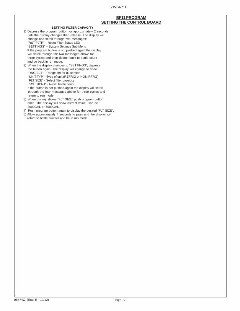
SETTING FILTER CAPACITY1) Depress the program button for approximately 2 seconds until the display changes then release. The display will change and scroll through two messages: “RST FLTR” – Reset Filter Status LED “SETTINGS” – System Settings Sub Menu If the program button is not pushed again the display will scroll through the two messages above for three cycles and then default back to bottle count and be back in run mode.2) When the display changes to “SETTINGS”, depress the button again. The display will change to show “RNG SET“- Range set for IR sensor. “UNIT TYP“ - Type of unit (REFRIG or NON-RFRG) “FLT SIZE” - Select filter capacity “RST BCNT“ - Reset bottle count If the button is not pushed again the display will scroll through the four messages above for three cycles and return to run mode.3) When display shows “FLT SIZE” push program button once. The display will show current value. Can be 3000GAL or 6000GAL.4) Push program button again to display the desired “FLT SIZE”.5) Allow approximately 4 seconds to pass and the display will return to bottle counter and be in run mode.

Page 13 98674C (Rev. E - 12/12)
LZWSR*1B
2.25
1.75
3.75 Bottom View of CoolerFig. 12
Alternate Filter Mounting LocationFig. 13
A
B
3/16” Dia.2 Holes
EXISTINGHOLE
1-3/8” Dia. Hole
SCREWS
PLASTIC BUSHING
SCREWS
FILTER MOUNTING BRACKETFILTER ASSEMBLY
ALTERNATE FILTER MOUNTING LOCATION
1) Using the supplied punch from the Bottle Filler installation, punch a 1-3/8” dia. hole “A” at the existing hole shown in Fig. 12.2) Drill two 3/16” dia. hole at location “B” shown in Fig 12.3) Remove Filter bracket from filter assembly and reinstall as shown in Fig. 13. Be sure the 3/8” water inlet is facing out.4) Install plastic bushing (supplied) as shown into 1-3/8” hole, bushing must be used so waterlines will not be cut by sharp edges of base plate.5) Install filter assembly to bottom of cooler as shown in Fig. 13 with 2-#8 sheet metal screws.6) Run the inlet and outlet water lines to filter.7) P/N 98551C - LZ Filter Mounting Cover (Light Gray Granite) or P/N 98568C - LZ Filter Mounting Cover (Stainless Steel) may be order to enclose the filter beneath the cooler (Not Shown).
3/8” WATER INLET
Page 1498674C (Rev. E - 12/12)
LZWSR*1B
PRINTED IN U.S.A.IMPRESO EN LOS E.E.U.U.IMPRIMÉ AUX É.-U.
FOR PARTS, CONTACT YOUR LOCAL DISTRIBUTOR OR CALL 1.800.323.0620PARA PIEZAS, CONTACTE A SU DISTRIBUIDOR LOCAL O LLAME AL 1.800.323.0620
POUR OBTENIR DES PIÈCES, CONTACTEZ VOTRE DISTRIBUTEUR LOCAL OU COMPOSEZ LE 1.800.323.0620
ELKAY MANUFACTURING COMPANY • 2222 CAMDEN COURT • OAK BROOK, IL 60523 • 630.574.8484
REPAIR SERVICE INFORMATION TOLL FREE NUMBER 1.800.260.6640NÚMERO GRATIS DE SERVICIO 1.800.260.6640
INFORMATIONS POUR LE SERVICE PAR NUMERO SANS FRAIS 1.800.260.6640
Fig. 14
DESCRIPTION
1234567
ITEM NO. PART NO.
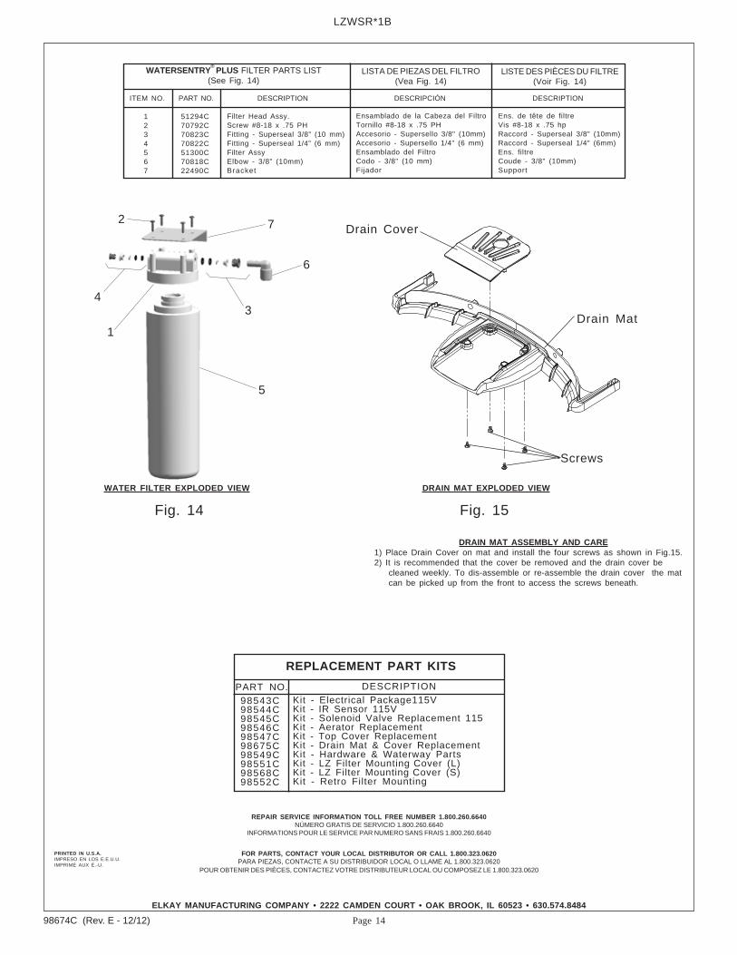
51294C70792C70823C70822C51300C70818C22490C
Filter Head Assy.Screw #8-18 x .75 PHFitting - Superseal 3/8” (10 mm)Fitting - Superseal 1/4” (6 mm)Filter AssyElbow - 3/8” (10mm)Bracket
DESCRIPCIÓN DESCRIPTION
Ensamblado de la Cabeza del FiltroTornillo #8-18 x .75 PHAccesorio - Supersello 3/8" (10mm)Accesorio - Supersello 1/4" (6 mm)Ensamblado del FiltroCodo - 3/8" (10 mm)Fijador
Ens. de tête de filtreVis #8-18 x .75 hpRaccord - Superseal 3/8" (10mm)Raccord - Superseal 1/4" (6mm)Ens. filtreCoude - 3/8" (10mm)Support
WATERSENTRY®
PLUS FILTER PARTS LIST(See Fig. 14)
LISTA DE PIEZAS DEL FILTRO(Vea Fig. 14)
LISTE DES PIÈCES DU FILTRE(Voir Fig. 14)
Fig. 15
1
2
34
5
6
7
WATER FILTER EXPLODED VIEW DRAIN MAT EXPLODED VIEW
Screws
Drain Cover
Drain Mat
DRAIN MAT ASSEMBLY AND CARE1) Place Drain Cover on mat and install the four screws as shown in Fig.15.2) It is recommended that the cover be removed and the drain cover be cleaned weekly. To dis-assemble or re-assemble the drain cover the mat can be picked up from the front to access the screws beneath.
DESCRIPTION
98543C98544C98545C98546C98547C98675C98549C98551C98568C98552C
Kit - Electrical Package115VKit - IR Sensor 115VKit - Solenoid Valve Replacement 115Kit - Aerator ReplacementKit - Top Cover ReplacementKit - Drain Mat & Cover ReplacementKit - Hardware & Waterway PartsKit - LZ Filter Mounting Cover (L)Kit - LZ Filter Mounting Cover (S)Kit - Retro Filter Mounting
REPLACEMENT PART KITS
PART NO.

Page 15 98674C (Rev. E - 12/12)
LZWSR*1B
BASIN TEMPLATE
O1
3/8
PUNC
HED
HOLE
O1/
2" PILO
THO
LE
1 3/
4"
1 1/
8"
EZH2
0 RE
TRO
-FIT
BOT
TLE
FILL
ERBA
SIN
HOLE
TEM
PLAT
E
CUT ALONG LINECU
T AL
ONG
LIN
E
LEFT SIDEW
ALL