Embed Size (px)
DESCRIPTION
InFusion Fundation Edition 2.0
Citation preview

System PlatformPart 1

Wonderware® System Platform – Part 1
Pablo Gerónimo TiradoApplications Engineer

8:30 AM
1:00 PM
10:00 AM
3:00 PM
4:30 PM
6:00 PM Silence your phones
At the lobby
Outside the bulding
On every computer
Entrance hall to your left
In the kitchen
Wonderware Training

Day
3D
ay 2
Day
1
Agenda Contents
Module 1: Introduction
Module 2: Application Infrastructure
Module 3: Application Objects
Module 4: Extending the Objects
Module 5: Alarms and History
Module 6: Security
Module 7: Galaxy Maintenance
Module 8: Device Integration Products
Module 9: Multi-Node Applications
System Platform – Part 1

Module 1:Introduction
Contents
Section 1: Course Introduction
Section 2: Wonderware System Platform
Lab 1 – Creating a Galaxy
Section 3: The ArchestrA IDE
Section 4: Automation Objects
Section 5: System Requirements, Licensing and Support
Section 6: Application Planning
Lab 2 – Identifying the Mixer
System Platform – Part 1

Course Description
The System Platform – Part 1 training course is a 4-day
instructor-led course designed to give the
knowledge necessary to develop and support
applications with Wonderware Application
Server.

Course Objectives► Create new projects using
ArchestrA® Integrated Development Environment
► Model the plant floor using automation objects
► Work with the alarm and history configuration in the Galaxy
► Configure ArchestrA® security in the Galaxy
► Troubleshoot Wonderware Application Server applications

Project Specific Work
QuickStart Applications
System Platform
Function Specific Modules
Microsoft Technology & Industry Standards
Clients
Wonderware System Platform

S/W Applications
3rd PartyData Sources
3rd Party Controllers
Wonderware System Platform
Historian(InSQL)
Application Server(IAS)
Information Server(SuiteVoyager)
Device Integration
Wonderware Clients
InTouch ViewAnalysis Client(ActiveFactory)
Reporting Client(SuiteVoyager CAL)
Wonderware System Platform

Application Server Evolution
IAS 1.0SupervisoryExecution
Engine
IAS 1.5Scalability
PerformanceRobustness
IAS 2.0/2.1Failover supportSCADA Support
InternationalizationObjects
Single Node
Application Server 3.0
Node by node upgradePerformance & Robustness
ArchestrA GraphicsIDE Update
ApplicationServer 3.x
Time PropagationScan On Demand
FY 2005 FY 2006FY 2007 Projections
ArchestrAGalaxies
10,000+ Platfor
ms Installe
d Already
Name change
2000
+
1000
+
430+

It is an open and extensible system of components based on a distributed, object-oriented design.
It provides a unified environment for visualization, plant history, device communications and automation application integration.
Application Server’s application, configuration information and project database.
ArchestrA
Application Server
Galaxy
Galaxy Repository
Single computer and software where the Galaxy database is located.
Concepts and Terminology

Concepts and Terminology
Galaxy
Platform
Engine
Container App Objects
App Objects
Attributes

Highlights
Leverage the .NET Framework for the Automation World
Object-based application
One global networked namespace
Centralized configuration and security
Multi-user development environment
Component-based plant application model
Self documenting
Advanced system maintenance and diagnostics
Line 1
Line 2
Production
Intake
Discharge
Wonderware Application Server
Evolution from HMI to AS
14
Navigation Scripts
Windows
Animation
Trends/Alarms, etc.
Security
Oper. Interface
Navigation Scripts
Windows
Animation
Trends/Alarms, etc.
Security
Oper. Interface
Remote references
PV
CLS
OLS
Cmd
LS_Alarm
Timeout_Alarm
PV
CLS
OLS
Cmd
LS_Alarm
Timeout_Alarm
PV
CLS
OLS
Cmd
LS_Alarm
Timeout_Alarm
CV101
CV102
CV103
$Valve
Traditional HMI
Introduction of Remote references
Tag server + Clients
Tag server – issues
IAS – Solution:
• Encapsulation in objects
• Derivation from templates
Represented by objects
Derived from templates
Process Data History
Alarm History
Event History
History
Alarm Groups
Access Names
Security & Users
Appl.
Application Scripts
Data Change Scripts
Condition Scripts
Window Scripts
SQL Access, Files, etc.
Other Supervisory Logic
Scripts
Tag names
Scaling
History Configuration
Engineering Units
Event Configuration
Alarm Configuration
Access Name Link
I/O Item names
Tags – Process Data
Navigation Scripts
Windows
Animation
Trends/Alarms, etc.
Security
Oper. Interface

15
CV101
CV102
CV103
One global and securename space for all process data
Navigation Scripts
Windows
Animation
Trends/Alarms, etc.
Oper. Interf.
Navigation Scripts
Windows
Animation
Trends/Alarms, etc.
Oper. Interf.
Navigation Scripts
Windows
Animation
Trends/Alarms, etc.
Oper. Interf.
Process Data History
Alarm History
Event History
History
IAS – Solution:
• Encapsulation in objects
• Derivation from templates
• One global name space
• Security at data level
Evolution from HMI to AS

16
CV103
Easy creation of objectinstances using “drag and drop” from
templates
CV102
CV101
Navigation Scripts
Windows
Animation
Trends/Alarms, etc.
Oper. Interf.
Navigation Scripts
Windows
Animation
Trends/Alarms, etc.
Oper. Interf.
Navigation Scripts
Windows
Animation
Trends/Alarms, etc.
Oper. Interf.
Process Data History
Alarm History
Event History
History
Evolution from HMI to AS
• One global name space
• Security at data level
IAS – Solution:
• Encapsulation in objects
• Derivation from templates

Object Oriented vs. Tag Based
Process Object Oriented Tag Based
Structure Hierarchical Flat
Graphics Development Done Last Done Early
Background Process Development in Objects Developed in Tags
Promotion of Standards Strictly Enforced Not Strictly Enforced
Global Application Change
Propagate from templates Change in tools like Excel
Data Represented by Physical Devices as Objects
Data Types and communication bits as
tags

Scalability
IntegratedSingle Node
Application ObjectServer Only
Single ServerMulti Client
Distributed Multi ServerMulti Client
DistributedPeer to Peer
Small System Large System

Enhanced CommunicationsIntercommunications is no longer performed by either NetDDE or SuiteLink.New Communications Protocol LMX/NMX (Local/Network Message Exchange):
Guaranteed Order of DeliveryEnhanced Diagnostics

History SchemeLogic / Scripting
Alarms & Events
Security
Automation Objects
Documentation
Graphics
Inputs & Outputs
$Valve
CV101
CV101
CV101
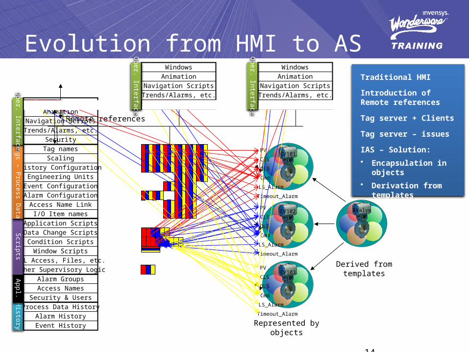
Templates and Instances
• Instances derived from templates and inherit all the configuration• New templates can be derived from existing templates• Changes to templates can be propagated to derived objects• Templates allow the development of a library of standard objects
Automation Objects

ArchestrA® TopologyWorkstation
I/O Data Server
Information Server
HistorianGalaxy Repository
ArchestrA Runtime
ArchestrA Runtime
Visualization Node Visualization Node Engineering Station Engineering Station

Workstation
I/O Data Server
Information Server
HistorianGalaxy Repository
ArchestrA Runtime
ArchestrA Runtime
Visualization Node Visualization Node Engineering Station Engineering Station
ArchestrA® Topology
Bootstrap
Platform
Galaxy Rep.
Bootstrap
Platform
Bootstrap
Platform
Historian
Bootstrap
Platform
Info Server
Bootstrap
Platform
InTouch
Bootstrap
Platform
InTouch
Bootstrap
Platform
IDE
Bootstrap
Platform
IDE
Bootstrap
Platform
IO Server

Engineering Station Workstation
I/O Data Server
Information Server
HistorianGalaxy Repository
Engineering Station
ArchestrA Runtime
ArchestrA Runtime
Visualization Node Visualization Node
Galaxy Rep. Historian Info Server
InTouch InTouch IDE IDE
IO Server
ArchestrA® Topology
Bootstrap
Platform
Bootstrap
Platform
Bootstrap
Platform
Bootstrap
Platform
Bootstrap
Platform
Bootstrap
Platform
Bootstrap
Platform
Bootstrap
Platform
Bootstrap
Platform Unified Name Space

System Requirements – Software
ArchestrA IDE ArchestrA Runtime Galaxy Repository
Windows Vista• Business• Enterprise• Ultimate
Windows Server 2003 SP2• Standard Edition• Enterprise Edition
Windows Server 2003 R2 SP2
• Standard Edition• Enterprise Edition
Windows XP
• Professional SP2• Tablet 2005
(Professional)
SQL Server 2005 SP2
• Standard• Enterprise
.Net Framework CLR 2.0.50727

System Requirements – Hardware
Minimum Recommended
CPU Single-Core 3 GHz Dual-Core 2 GHz
RAM 1 Gb 2Gb
Minimum
CPU Single-Core 2 GHz
RAM 1 Gb
Minimum
Hard Drive 30 Gb available
Display SVGA (1024x768)
Optical Drive CD-ROM
Input Device Keyboard and Mouse
Galaxy Repository
ArchestrA IDE and Runtime
All Systems

This refers to the total application model that resides in the Galaxy Repository.
Number of I/O points being access into the Galaxy.
Number of PCs in the Galaxy that will be part of the single namespace.
Galaxy
IO Count
Platform Count
IDE
Integrated Development Environment for configuring the Galaxy
Concepts and Terminology

Licensing
IO Count History Platforms
250 250 2
250 1,000 2
1,000 1,000 2
1,000 5,000 2
5,000 1,000 3
5,000 5,000 3
5,000 12,000 3
5,000 25,000 3
25,000 5,000 3
25,000 12,000 3
25,000 25,000 4
25,000 50,000 4
50,000 12,000 4
WW System Platform
IO Count History Platforms
50,000 25,000 4
50,000 50,000 4
50,000 100,000 4
100,000 25,000 4
100,000 50,000 4
100,000 100,000 4
200,000 25,000 4
200,000 50,000 4
200,000 100,000 4
500,000 50,000 4
500,000 100,000 4
1,000,000 50,000 4
1,000,000 100,000 4

Licensing
Galaxy IO - Can Connect to a Galaxy of this Size
InTouch Tags History Tags(24Hr data retrieval)
Unlimited Any Size 60,000 500
Large 5,000 3,000 500
Medium 1,000 1,000 100
Small 250 500 100
Limited** NA 64 NA
** Limited – Includes InTouch Dev/RT (IDE) and Device Integration only; does not include AF, WIS, or Historian Server. Just like the 64 Tag InTouch Development Today.
Unlimited includes ActiveFactory.
WW Development Studio

LAB 1Creating a Galaxy
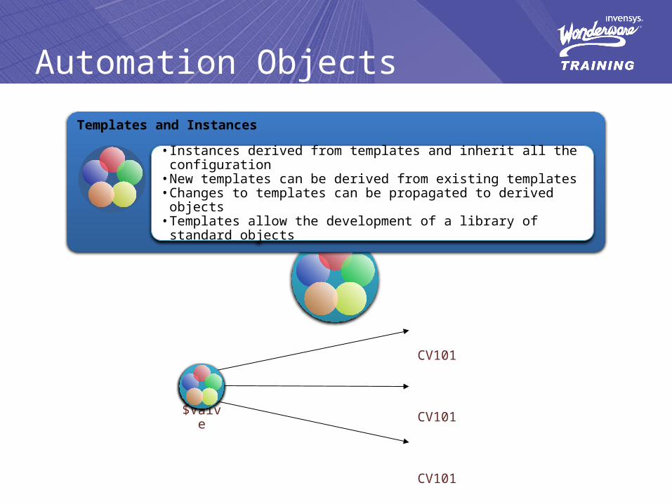
Suggested Project Workflow
Identify Field Devices and Functional Requirements
Defined Naming Conventions
Defined the Plant Model
Plan Templates
Defined the Security Model
Defined the Deployment Model

LAB 2Identifying the Mixer

Mixer System
LAB 2Identifying the Mixer
Heat Exchanger

LAB 2Identifying the Mixer

LAB 2Identifying the Mixer

Module 2:Application Infrastructure
Contents
Section 1: The Plant Model
Lab 3 – Creating the Plant Model
Section 2: The Deployment Model
Lab 4 – Creating and Deploying the Deployment Model
Section 3: The Runtime Environment
Lab 5 – Using Object Viewer
Section 4: Connecting to the Field
Lab 6 – Connecting to the Field
System Platform – Part 1

Plant
The Plant Model
Section
Area
Production Line
Manufacturing Cell
Area
Production Line
Manufacturing Cell
SectionArea Production Line
Manufacturing Cell
Section

Plant
Production
LAB 3Creating the Plant Model
Dis
cha
rge
Line1
Line2
Inta
ke
ControlSystem

Bootstrap
The Deployment Model
Platform
AppEngine
Area
DI Object
DI Object
Area
AppEngine
Area
DI Object
DI Object
Area

LAB 4Creating the Deployment Model

LAB 5Using Object Viewer

Connecting to the Field
Legacy InTouch Node
Field DeviceDeviceDriver

Galaxy
InControl
LAB 6Connecting to the Field
Field DeviceDeviceDriver

Module 3:Application Objects
Contents
Section 1: Templates and Instances
Section 2: The $UserDefined Object
Lab 7 – Heat Exchanger
Section 3: Change Control and Propagation
Lab 8 – Change Control and Propagation
Section 4: The $AnalogDevice Object
Lab 9 – Meter
Section 5: The $DiscreteDevice Object
Lab 10 – Valve, Pump and Motor
Section 6 – Containment
Lab 11 – Mixer
System Platform – Part 1

Templates
Base Template
Core objects created with the ArchestrA® Object Toolkit
Contain the base attributes and functionality of the object
Read-Only configuration
Templates created from another template within the ArchestrA®
IDE
Inherits the attributes, functionality and configuration
from the parent template
Writeable configuration
Derived Template

Template
$DiscreteDevice $Valve
$Inlet
$CV101
$Outlet
$CV102
$CV103
$CV104

LAB 7Heat Exchanger
TC1TC2
TC3 TC4

Control of Changes and Propagation
Locking Attributes
Locking an attribute prevents changes of that attribute on derived objects (templates and instances).
Locking attributes helps to establish standards in the galaxy.
Locking an attribute locks that attribute all the way down on the derivation hierarchy.
Unlocking an attribute releases the “locking control” only one level down.

Control of Changes and Propagation
$DiscreteDevice
Locked
Unlocked
Locked In Parent
$Valve
$Inlet
$CV101
$Outlet
$CV102
$CV103
$CV104

LAB 8Change Control and Propagation

LAB 9Meter
INLET 1
INLET 2
OUTLET
PUMP 1
PUMP 2
AGITATOR
LIT
TT
$Meter
INLET 1
INLET 2
OUTLET
PUMP 1
PUMP 2
AGITATOR
LIT
TT
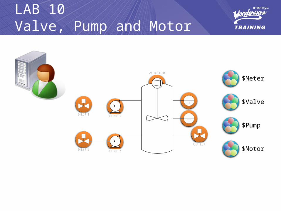
LAB 10Valve, Pump and Motor
$Meter
$Pump
$Motor
$Valve

ContainmentContainment
• Allows more advanced structures to be modeled as a single object.• Container and contained objects are still accessible as individual objects.• Relationship can be build at the template or instance level.
Inlet Valve$InletValve
Level Meter$LevelMeter
Outlet Valve$OutletValve
Agitator$Agitator
$Tank

INLET 1
INLET 2
OUTLET
PUMP 1
PUMP 2
AGITATOR
LIT
TT
LAB 11Mixer
$Meter
$Pump
$Motor
$Valve
$Mixer

Module 4:Extending the Objects
Contents
Section 1: UDAs
Section 2: Extensions
Lab 12 – Motor Speed
Section 3: Introduction to QuickScripts .NET
Lab 13 – DDESuiteLinkClient Auto Reconnect
Lab 14 – Automatic Reference Configuration
System Platform – Part 1

UDA Categories
CalculatedCalculated Retentive
Object Writeable
User Writeable
SameObject
OtherObjects
ExternalUsers

Extensions
59

LAB 12Motor Speed

Relative References
Me
MyContainer
MyArea
MyEngine
MyPlatform
MyHost

Executing an Object
The object will…
1. Get all the inputs values referenced in the object2. Execute all After Input scripts3. Execute the Internal Behavior4. Execute all Before Outputs5. Writes all the outputs values
Attributes
Inputs Scripts Behavior Scripts Outputs

Scheduler 2.1
Execute App Objects
Send changes to other engines
Prepare check-point data
Read Queued Input
Write checkpoint data in separate thread
Read Inputs /Idle
All Inputs are up to date at the start of the next scan.
Execute DI’s – read/write values to server

Scheduler 3.0
Execute App Objects
Send changes to other engines
Prepare check-point data
Read Queued Input
Write checkpoint data in separate thread
Read Inputs /Idle
All Inputs are up to date at the start of the next scan.
Execute DI’s – read/write values to server
Read/Write interrupts
Read/Write interrupts

LAB 13DDESuiteLinkClient Auto Reconnect

LAB 14Automatic Reference Configuration

Module 5:Alarms and History
Contents
Section 1: Alarms
Lab 15 – Configuring Alarms
Section 2: Historization
Lab 16 – Configuring History
System Platform – Part 1

Alarms
Alarm Engine
• Alarms are generate by the objects.
• Alarm providers make the alarms available to external alarm subscribers.
• Available alarm subscribers allows:• Visualization and acknowledge
of alarms• Logged alarms into a SQL
Server database

Alarms
WinPlatform
AppEngine
Area
Alarm Viewer
Alarm DB Logger
PR
OV
Alarm Provider
• $WinPlatform object as the InTouch Alarm Provider for the galaxy.• A single $WinPlatform can provide alarms from the whole galaxy.• Alarm providers can be limited to provide alarms for specific areas of the galaxy.

Alarms
Production
Plant
Discharge
Intake
Line1
Line2
BlueNode RedNode
Production
Discharge
Intake
Line1
Line2
\\BlueNode\Galaxy!Plant
Line1Line2
IntakeDischarge
\\RedNode\Galaxy!Plant
Production
Line1 Line2

LAB 15Configuring Alarms
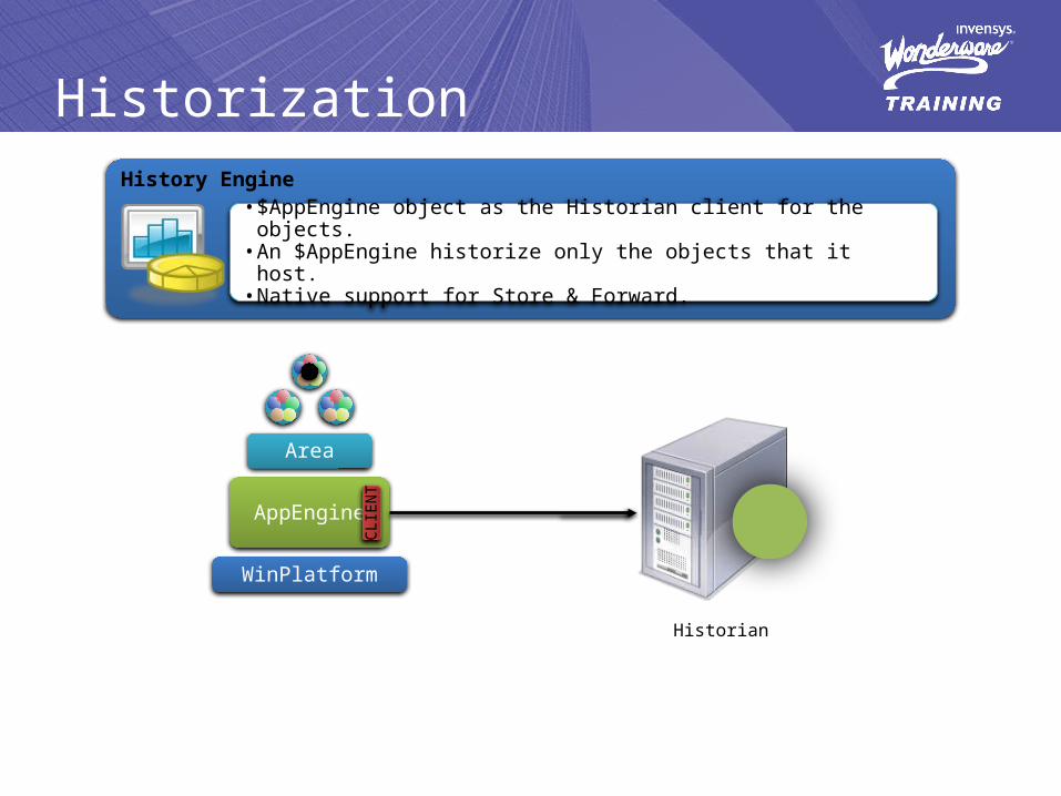
WinPlatform
AppEngine
Historization
Area
CLI
EN
T
History Engine
• $AppEngine object as the Historian client for the objects.• An $AppEngine historize only the objects that it host.• Native support for Store & Forward.
Historian

InSQL
Historization•Classic InSQL Behavior:
The IDAS component behaves as a DDE/SuiteLink client.
Data is read/acquired by InSQL.
InSQL plays an ACTIVE role in the data acquisition process.
• InSQL and IAS: History is sent using the MDAS
component.
The AppEngine initialize the communication and write/sent the data.
InSQL plays a PASSIVE role in the data acquisition process.
IDASMDAS
Application Server
InTouchIOS

LAB 16Configuring History

Module 6:Security
Contents
Section 1: Security Overview
Lab 17 – Security
System Platform – Part 1

DevelopmentSecurity
Runtime Security
Security
DevelomentTesting
TroubleshootingEnvironment
Security GroupsBELONGS TO
ONE OR MOREOPERATIONALPERMISSIONS
ASSIGNED TOATTRIBUTES
GEN
ERAL
PERM
ISSI
ON
S
RolesSecurityClassifications Users
Security Audit Trail
• The Galaxy generates an event for every user-generated write to an attribute.
• Alarm DB Logger is used to log the events.
• Use the v_EventHistory view in the alarm database to query events.

LAB 17Security

Module 7:Galaxy Maintenance
Contents
Section 1: Exporting and Importing Objects
Section 2: Configuring Instances Through a CSV File
Section 3: System Management Console (SMC)
Section 4: Network Account Utility
System Platform – Part 1

Module 8:Device Integration Products
Contents
Section 1: I/O Servers
Section 2: Data Access Servers
Section 3: Device Integration Objects
System Platform – Part 1

DA ServerDAS Engine
Device Integration Products
I/O Data Server
ArchestrA Runtime
IO Server
DDE SuiteLink
PLC Protocol
DDE SuiteLink OPC
PLC Protocol
IO Servers and DA Servers
• Communications between the Galaxy and field devices is achieved through Device Integration Products.
• Supported protocols include DDE, SuiteLink and OPC.
• New internal architecture for DA Servers provides independency between components.
DDE SuiteLink OPC
PLC Protocol

DA Servers and DI Objects
I/O Data Server
PLC5_A
SLC_A
PLC_1
CNET
DHP
NIC
PLC_2
SLC_B
PLC5_B

Module 9:Multi-Node Applications
Contents
Section 1: Application Redundancy
Lab 18 – Configuring Application Redundancy
Section 2: DI Redundancy
Lab 19 – Configuring the Redundant DI Object
Section 3: Multi-Node Application
Lab 20 – Convert to Network Environment
System Platform – Part 1

Application Redundancy
ArchestrARuntime
ArchestrARuntime
Client/Server ArchitectureNon-Redundant System
The server handles all the data.
If server if lost, client lose connection to all data:
• InTouch• Historian• Other Application Object
Servers
Redundant System
Redundant server maintain synchronized data through dedicated network.
If the primary server is lost, the backup server will take over.
The switch between the servers is transparent to the clients.

Application Redundancy
Platform1
Characteristics
Currently supported only in pairs
Second network connection (RMC) necessary
Configuration Terminology:• Primary AppEngine• Backup AppEngine
Runtime Terminology• Active AppEngine• Standby AppEngine
Active AppEngine refer to Standby AppEngine as Partner.
RMC
ArchestrA
Platform2
AppEngine1(Backup)
Primary Backup
AppEngine1
Active StandbyStandby Active

Redundant Message Channel
Automatic Synchronization
1. Current data (Checkpoint)
2. Alarm states and times
3. History store and forward blocks
4. Deployed objects and configuration
5. AppEngine status
RMC
ArchestrA
Active Standby
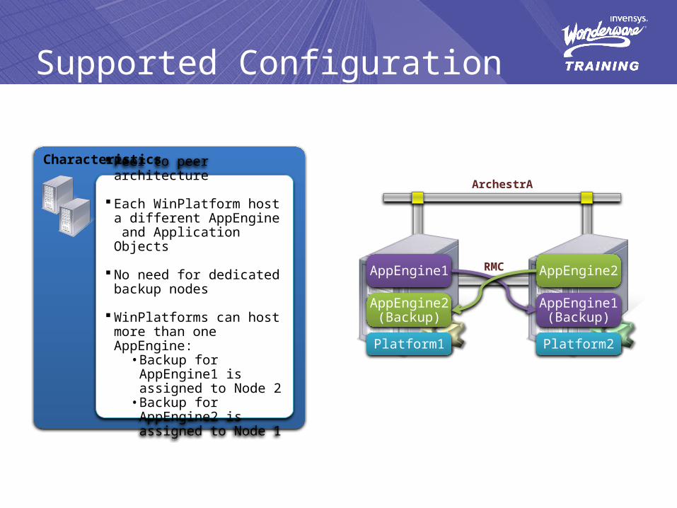
Supported Configuration
Platform1
Characteristics
Peer to peer architecture
Each WinPlatform host a different AppEngine and Application Objects
No need for dedicated backup nodes
WinPlatforms can host more than one AppEngine:
• Backup for AppEngine1 is assigned to Node 2
• Backup for AppEngine2 is assigned to Node 1
RMC
ArchestrA
Platform2
AppEngine1(Backup)
AppEngine2(Backup)
AppEngine2AppEngine1

Redundancy Configuration
Windows Networking
1. Install 2nd network card.
2. Configure the ArchestrA connection to be accessed before the RMC connection.
3. Give the RMC connection a fixed IP address in a different Subnet than the ArchestrA connection.
Wonderware® Application Server
1. Configure the WinPlatforms with their corresponding local RMC IP addresses.
2. Configure the AppEngine to be redundant.
3. Assign the AppEngines (Primary and Backup) to the WinPlatforms.

LAB 18Configuring Application Redundancy

CIP DH+
DI Redundancy
ArchestrARuntime
Field Device Connectivity
Loss of the control network would cause the server to lose connection to data.
The Redundant DI Object allows communications through a Standby network if the Active is lost.
The Redundant DI Object allows Applications Objects to subscribe to a single object that in turn can retrieve data from either a Primary or Backup DI object.

DH+
CIP
DI Redundancy
DIO_2DIO_1
RDIO
ApplicationObjects
Platform1
Control Networks
AppEngine1 DAServer (A) DAServer (B)

LAB 19Configuring Redundant DI Object

LAB 20Convert to Network Environment
Platform
AppEngine
Platform
AppEngine
Platform
AppEngine
Platform
AppEngine
MyTemplates.aaPKG MyTemplates.aaPKG MyTemplates.aaPKG
ArchestrA IDE ArchestrA IDE ArchestrA IDE ArchestrA IDE
MyTemplates.aaPKG
InControl.aaPKG
Galaxy Master Remote Node Remote Node Remote Node
1. Undeploy local (current) Galaxy2. Export objects3. Select Galaxy Master
4. Create new galaxy on Galaxy Master5. Create and deploy platforms6. Import objects

LAB 20Convert to Network Environment
Platform
AE
Platform
AE
Platform
AE
ArchestrA IDE ArchestrA IDE ArchestrA IDE ArchestrA IDE
Galaxy Master Remote Node Remote Node Remote Node
Platform
AE AEDI

Powering intelligent plant decisions in real time.