Embed Size (px)
Citation preview

productInformation on gas burners
Weishaupt monarch® gas burner, WM-G10 (65 –1250 kW)
Precision as standard
2
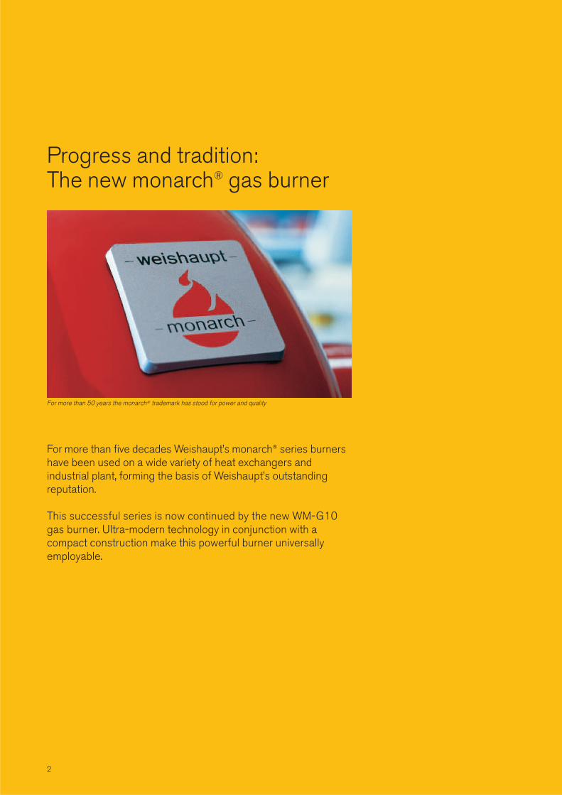
For more than five decades Weishaupt’s monarch® series burnershave been used on a wide variety of heat exchangers and industrial plant, forming the basis of Weishaupt’s outstanding reputation.
This successful series is now continued by the new WM-G10gas burner. Ultra-modern technology in conjunction with a compact construction make this powerful burner universally employable.
For more than 50 years the monarch® trademark has stood for power and quality
Progress and tradition:The new monarch® gas burner

3
Digital. Compact. Quiet.The aerodynamic housing andspecial air feed enable a highercapacity within smaller dimensions.
Digital combustion managementfor economical and safe burneroperation. The controls are easyto use.
The new monarch burners operate with considerably reduced noise levels, thanks tothe newly developed fan unit.

Burner motor with integralcontactor
Flame monitoringDigital combustion managerand burner-mounted controland display unit
Protective grill
Air damper stepping motor
Sound attenuated air inlet
Air pressure switch
Fan wheel
Air damper
Gas butterfly stepping motor
Burner housing can behinged open to the leftor right hand side
Mixing assembly

5
WM-G10 Weishaupt monarch® burner:Top design, technology and qualityThe new WM-G10 Weishaupt monarch® burner is the logically consistent further development ofthe legendary monarch® series. This completely newly developedburner generation is considerablymore compact, powerful and quietand reaffirms Weishaupt’s burnerconstruction expertise.
Futuristic fan technologyRight from the earliest developmentalstages of this new burner generation,particular emphasis was placed on acompact, aerodynamic construction andlow operational noise levels. To realisethis goal, a completely new air inlet andair damper control were developed.The special housing design with the selfopening air inlet, together with the newair damper technology, results in increased fan pressure and thus morecapacity from a more compact form.The air damper control provides a highdegree of linearity even at the lower endof the operating range and combinedwith the sound attenuated air inlet,which is included as standard, ensuresquieter operation.
Fast commissioning, simple servicingAll WM-G10 burners are delivered withthe mixing assembly preset for the required output of the burner. A final adjustment is made using the combustion manager’s menu controlledcommissioning program. All the burner’scomponents, such as the mixingassembly, air damper and combustionmanager, are readily accessible despiteits compact construction, enabling maintenance and servicing work to becarried out quickly and easily. This is further helped by the standard hingedflange, which provides a perfect servicing position for the burner. Adjustment to suit different combustionchamber conditions can be easily carriedout on the burner in its installed position.The integral sightglass enables ignitionand the flame to be observed.
Low NOX operationLow NOx figures are dependent on combustion chamber geometry and volumetric loading. NOx figures and thenecessary combustion chamber dimensions can be found in the publication “Conditions for attaining theNOx emission values for burners.”
FuelsNatural Gas ENatural Gas LLLiquid Petroleum Gas B/P
ApplicationsThe Weishaupt WM-G10 gas burner issuitable for:• installation on heat exchangers to
EN 676 and EN 303-2• hot water plant• steam boilers and high pressure hot
water plant• intermittent and continuous operation• installation on air heaters
The combustion air must be free of aggressive substances (halogens, chlorides, fluorides etc.) and impurities (dust, debris, vapours etc.).For some applications the use of an extraneous air supply is recommended(additional cost).
Permissible ambient conditions• Ambient temperature:
-15 to +40°C (in operation)• Humidity: max. 80% relative
humidity, no dew point• Suitable for operation indoors only• For plant in unheated areas certain
further measures may be required(please enquire)
Use of the burner for applications or in ambient conditions not detailed above isnot permitted without the prior writtenagreement of Max Weishaupt GmbH.The service intervals will be reduced inaccordance with the more extreme operational conditions.
CertificationThe burners are tested by an independent body and conform to thefollowing standards and EU directives:• EN 676 (LN version has best, Class 3
emission levels for natural gas)• Machinery Directive 98/37/EC• Electromagnetic compatability
EMV 89/336/EEC• Low Voltage Directive73/23/EEC• Gas Appliance Directive
90/396/EEC• Pressure Vessel Directive 97/23/EC• The burners carry the CE and CE-PIN
marks
The most important advantages at aglance• Digitial combustion management at all
ratings• More compact than previous burners
of a similar rating• Sound attenuated air inlet as standard
for quieter operation• Powerful fan due to the specially
developed fan geometry and air damper control
• All WM-G10 burners are delivered with the mixing assembly preset for the required output of the burner
• IP 54 protection as standard• Easy access to all components, such
as: mixing assembly, air damper and combustion manager
• Safe operation with sliding two stageor modulating operation as standard
• Computer controlled function test atthe factory of each individual burner
• Burner can be supplied pre-wired with plug connections
• Excellent price/capacity ratio• Well established, global service
network

6
Digital combustion management:Precise, simple and safe
Digital combustion managementmeans optimal combustion figures,continually reproducible setting figures and ease of use.
Weishaupt WM-G10 gas burners areequipped as standard with electroniccompound regulation and digital combustion management. Modern combustion technologies demand aprecise, continually reproducible dosingof fuel and combustion air. Only in thisway can optimal combustion figures beensured over extended periods.
Simple operationSetting and control of the burner isachieved using a control and displayunit. The CDU is linked to the combustion manager via a bus system,enabling the user friendly setting of theburner.
Flexible communication possibilitiesThe integral interface enables all necessary information and functions tobe relayed to a superordinate controlsystem. If required, a modem enables atelephone connection to be installed forremote operation, monitoring and diagnosis.
Communication with external systems via busSeveral bus systems are availabe via theE-Gate if data from the burners are tobe exchanged with a PLC unit, or if the burners are to be integrated into abuilding management system. For thecontrol and management levelsWeishaupt offers ProGraf NT, a realtime software product to meet any andall requirements.
New technology advantagesDigitial combustion management makes burner operation simple andsafe. The most important advantages:
• No additional burner controls are necessary as control is effected by the combustion manager. The only additional requirements are control and motor fuses (by others).
• Reduced installation expense: Each burner is tested and supplied bythe factory as a complete unit.
• Commissioning and service work takes less time. The burner’s basic parameters are set at the factory. Adjustment to site conditions and combustion emission checks are effected via the combustion manager’s menu controlled commissioning program.
Input and control via the control and display unit (e.g. W-FM 50)

7
Example with W-FM 50 (standard from 2006)
W-FM 50 orW-FM 100/200combustion manager
Control anddisplay unit
DDC
Stepping motorfor air feed
BMS visualisatione.g. ProGraf NT by Neuberger
Stepping motorfor gas feed
8
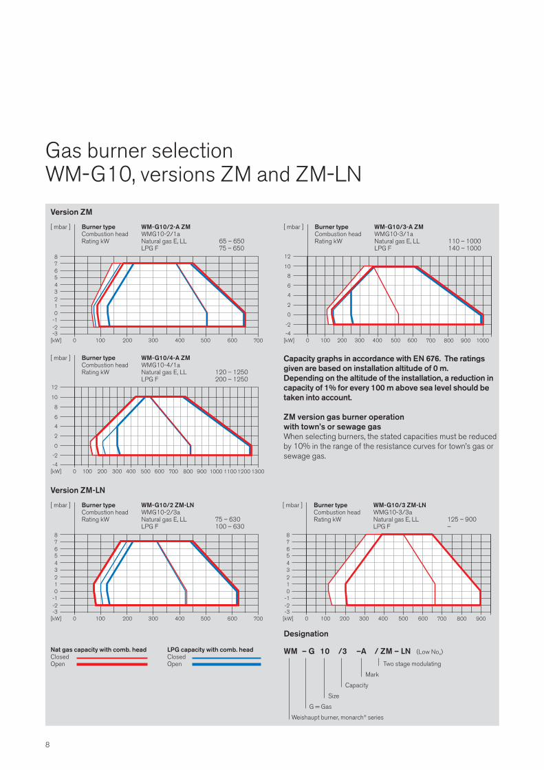
Gas burner selectionWM-G10, versions ZM and ZM-LN
4
2
0
0 100[kW] 200 700-4
300 400 500 600
-2
6
8
800 900 1000
10
12
[ mbar ] Burner type WM-G10/3-A ZMCombustion head WMG10-3/1aRating kW Natural gas E, LL 110 – 1000
LPG F 140 – 1000
10
8
6
4
2
0 100[kW] 200 700-4
300 400 500 600
0
12
-2
800 900 1000 1100 1200 1300
[ mbar ] Burner type WM-G10/4-A ZMCombustion head WMG10-4/1aRating kW Natural gas E, LL 120 – 1250
LPG F 200 – 1250
43210
0 100[kW] 200 700-3
300 400 500 600
-1
5
-2
678
[ mbar ] Burner type WM-G10/2-A ZMCombustion head WMG10-2/1aRating kW Natural gas E, LL 65 – 650
LPG F 75 – 650
Nat gas capacity with comb. head LPG capacity with comb. headClosed ClosedOpen Open
43210
0 100[kW] 200 700-3
300 400 500 600
-1
5
-2
678
800 900
[ mbar ] Burner type WM-G10/3 ZM-LNCombustion head WMG10-3/3aRating kW Natural gas E, LL 125 – 900
LPG F –
43210
0 100[kW] 200 700-3
300 400 500 600
-1
5
-2
678
[ mbar ] Burner type WM-G10/2 ZM-LNCombustion head WMG10-2/3aRating kW Natural gas E, LL 75 – 630
LPG F 100 – 630
Capacity graphs in accordance with EN 676. The ratingsgiven are based on installation altitude of 0 m.Depending on the altitude of the installation, a reduction incapacity of 1% for every 100 m above sea level should betaken into account.
ZM version gas burner operation with town’s or sewage gasWhen selecting burners, the stated capacities must be reducedby 10% in the range of the resistance curves for town’s gas orsewage gas.
Version ZM-LN
Version ZM
Designation
WM – G 10 /3 –A / ZM – LN (Low Nox)
Two stage modulating
Mark
Capacity
Size
G = Gas
Weishaupt burner, monarch® series

9
Technical dataScope of delivery
Burner WM - G10/2-A / ZM WM - G10/3-A / ZM WM - G10/4-A / ZM
Burner motor Weishaupt type D90/50-2 D90/90-2 D90/90-2
Nominal capacity kW 0.76 1.5 1.5
Nominal load A 2.1 3.5 3.5
Motor prefuse (�∆ start) A minimal 10 A slow (external) 10 A slow (external) 10 A slow (external)
Speed (50 Hz) rpm 2850 2800 2800
Combustion manager Type W-FM 100 (W-FM 50)1) W-FM 100 (W-FM 50)1) W-FM 100 (W-FM 50)1)
Air stepping motor Type SQM 45 (STE 50)1) SQM 45 (STE 50)1) SQM 45 (STE 50)1)
Gas stepping motor Type SQM 45 (STE 50)1) SQM 45 (STE 50)1) SQM 45 (STE 50)1)
NOx class in accordance with EN 676 1 1 1
Weight kg approx. 54 approx. 56 approx. 56
Burner WM - G10/2-A / ZM-LN WM - G10/3-A / ZM-LN
Burner motor Weishaupt type D90/50-2 D90/90-2
Nominal capacity kW 0.76 1.5
Nominal load A 2.1 3.5
Motor prefuse (�∆ start) A minimal 10 A slow (external) 10 A slow (external)
Speed (50 Hz) rpm 2800 2800
Combustion manager Type W-FM 100 (W-FM 50)1) W-FM 100 (W-FM 50)1)
Air stepping motor Type SQM 45 (STE 50)1) SQM 45 (STE 50)1)
Gas stepping motor Type SQM 45 (STE 50)1) SQM 45 (STE 50)1)
NOx class in accordance with EN 676 3 3
Weight kg ca. 54 ca. 56
Technical data
Description WM-G10/2-A / ZM WM-G10/3-A / ZM WM-G10/4-A / ZM WM-G10/2-A / ZM-LN WM-G10/3-A / ZM-LN
Burner housing, hinged flange, housing ● ● ● ● ●
cover, Weishaupt burner motor, air inlet,cover, fan wheel, combustion head, ignitionunit, ignition cable, ignition electrodes,combustion manager with control and display unit, flame sensor, stepping motors, flangegasket, hinged flange with limit switch, fixingscrews.
Combustion manager W-FM 100 (W-FM 501)) ● ● ● ● ●
Double gas solenoid valves (DMV), Class A ● ● ● ● ●
Gas butterfly valve ● ● ● ● ●
Valve connection piece ● ● ● ● ●
Air pressure switch ● ● ● ● ●
Low gas pressure switch ● ● ● ● ●
Adjustable regulating sleeve ● ● ● ● ●
in the mixing assembly
Stepping motor for gas butterfly and air damper ● ● ● ● ●
Note: In accordance with EN 676 gas filters and governors form part of the burner supply (see Weishaupt accessories list).Burner execution complies with TRD 604, 24 h / 72 h (see technical brochure, print No. 863).
1) Standard from 2006
Scope of delivery
Voltages and frequencies:The burners are equipped as standard for three phase alternating current 400 V, 3~, N, 50 Hz. Other voltages andfrequencies available on request.
Standard burner motor:Isolation class F, IP 54 protection.

10
Valve train sizingWM-G10, version ZM
WM-G10/3, version ZMBurner Low pressure supply (flow High pressure supply (flowrating pressure in mbar before shut pressure in mbar before kW off valve, pe,max = 300 mbar) double solenoid valve)
Nominal diameter of DMV Nominal diameter of DMV3/4” 1” 11/2” 2” 65 80 100 3/4” 1” 11/2” 2” 65 80 100
Nom. diameter of gas butterfly Nom. diameter of gas butterfly50 50 50 50 50 50 50 50 50 50 50 50 50 50
Natural Gas E Hi = 37.,26 MJ/m3 (10.35 kWh/m3), d = 0.606500 104 34 14 11 9 - - 54 12 7 7 6 - -550 124 40 16 12 10 8 8 65 14 8 8 6 6 5600 147 46 18 14 10 9 9 77 17 9 9 7 6 6650 171 53 20 15 11 10 9 90 19 10 10 8 7 6700 198 61 22 17 12 10 10 104 22 11 11 8 7 7750 226 69 25 18 13 11 10 119 24 13 12 9 8 8800 257 78 27 20 14 12 11 135 27 14 14 10 9 8850 - 87 30 22 15 13 12 - 30 15 15 11 9 9900 - 97 33 24 16 13 12 - 33 17 16 12 10 9950 - 107 36 26 17 14 13 - 37 18 18 13 11 101000 - 118 39 28 19 15 13 - 40 20 19 13 11 10
Natural Gas LL Hi = 31.79 MJ/m3 (8.83 kWh/m3), d = 0.641 500 148 46 17 13 10 9 8 77 16 9 9 7 6 5550 178 55 20 15 11 9 9 93 19 10 10 7 6 6600 210 64 23 17 12 10 9 110 22 11 11 8 7 7650 246 74 26 19 13 11 10 129 25 13 13 9 8 7700 - 85 29 21 15 12 11 - 29 14 14 10 8 8750 - 97 33 23 16 13 11 - 33 16 16 11 9 9800 - 110 36 26 17 14 12 - 37 18 17 12 10 9850 - 123 40 28 18 15 13 - 41 20 19 13 11 10900 - 137 44 31 20 15 14 - 45 21 21 14 11 11950 - 152 48 33 21 16 14 - 50 23 23 15 12 111000 - 167 53 36 23 17 15 - 55 25 25 16 13 12
LPG B/P Hi = 93.20 MJ/m3 (25.89 kWh/m3), d = 1.555 500 46 17 - - - - - 24 7 - - - - -550 54 20 10 8 - - - 29 8 5 5 - - -600 64 23 11 9 - - - 34 9 6 6 - - -650 74 26 12 10 8 - - 39 10 7 6 5 - -700 85 29 13 11 9 8 - 45 11 7 7 6 5 -750 97 33 14 12 10 9 8 51 13 8 8 6 6 6800 110 36 16 13 10 9 9 58 14 9 8 7 6 6850 123 40 17 13 11 10 9 65 15 9 9 7 7 7900 137 44 18 14 11 10 10 73 17 10 10 8 7 7950 152 49 20 15 12 11 10 81 18 11 11 8 8 71000 168 53 21 16 13 11 10 89 20 12 11 9 8 8
WM-G10/4, Ausf. ZMBurner Low pressure supply (flow High pressure supply (flowrating pressure in mbar before shut pressure in mbar before kW off valve, pe,max = 300 mbar) double solenoid valve)
Nominal diameter of DMV Nominal diameter of DMV1” 11/2” 2” 65 80 100 1” 11/2” 2” 65 80 100
Nom. diameter of gas butterfly Nom. diameter of gas butterfly50 50 50 50 50 50 50 50 50 50 50 50
Natural Gas E Hi = 37.,26 MJ/m3 (10.35 kWh/m3), d = 0.606600 45 17 12 9 - - 15 8 8 6 - -700 60 21 16 11 10 9 21 11 10 8 7 6800 78 27 19 14 11 10 27 14 13 10 8 8900 96 32 22 15 12 11 32 16 15 11 9 81000 117 37 25 16 13 11 38 18 17 12 10 91100 139 44 29 19 14 12 45 20 19 13 10 91200 164 50 33 21 15 13 53 23 21 14 11 101250 177 54 35 22 16 13 57 25 23 15 11 10
Natural Gas LL Hi = 31.79 MJ/m3 (8.83 kWh/m3), d = 0.641 600 63 22 16 11 9 8 21 10 10 7 6 5700 85 28 20 14 11 10 28 14 13 9 8 7800 109 36 25 17 13 12 36 17 16 12 10 9900 136 43 30 19 15 13 45 20 19 13 11 101000 166 51 35 21 16 14 54 24 22 15 12 101100 199 60 40 24 17 15 63 28 26 17 13 111200 235 70 46 27 19 16 74 32 29 19 14 121250 254 75 49 28 20 16 80 34 31 20 15 13
LPG B/P Hi = 93.20 MJ/m3 (25.89 kWh/m3), d = 1.555 600 22 - - - - - 8 - - - - -700 28 13 10 8 - - 11 7 6 5 - -800 36 16 12 10 9 9 14 9 8 7 6 6900 44 18 14 11 10 9 17 10 9 8 7 71000 52 20 15 12 10 9 19 11 10 8 7 71100 62 22 17 12 10 10 22 11 11 8 7 71200 72 25 18 13 11 10 25 12 12 9 8 71250 77 26 19 13 11 10 26 13 12 9 8 7
For valve train sizing with town’s gas and sewage gassee separate worksheet, print No. 900.
The CE-PIN No. is not valid for ZM version gas burnersoperating on town’s gas or sewage gas.Applicable additional and accessory prices, as well as conditions which must be adhered to, are available onrequest.
WM-G10/2, version ZMBurner Low pressure supply (flow High pressure supply (flowrating pressure in mbar before shut pressure in mbar before kW off valve, pe,max = 300 mbar) double solenoid valve)
Nominal diameter of DMV Nominal diameter of DMV3/4” 1” 11/2” 2” 65 3/4” 1” 11/2” 2” 65
Nom. diameter of gas butterfly Nom. diameter of gas butterfly40 40 40 40 40 40 40 40 40 40
Natural Gas E Hi = 37.,26 MJ/m3 (10.35 kWh/m3), d = 0.606300 40 15 - - - 21 6 - - -350 53 19 - - - 28 7 - - -400 68 24 11 9 - 36 9 6 6 -450 85 29 13 10 9 45 11 7 7 6500 104 34 15 12 9 55 13 8 8 6550 125 40 17 13 10 66 15 9 9 7600 148 47 19 15 11 78 17 10 10 8650 172 54 21 16 12 91 20 11 11 9
Natural Gas LL Hi = 31.79 MJ/m3 (8.83 kWh/m3), d = 0.641 300 56 20 - - - 30 8 - - -350 75 25 11 9 - 39 10 6 6 -400 97 32 13 11 9 51 12 7 7 6450 121 39 16 12 10 64 14 8 8 6500 148 47 18 14 11 78 17 9 9 7550 178 56 21 16 12 94 20 11 11 8600 211 65 24 18 13 111 23 12 12 9650 247 75 27 20 14 130 26 14 13 10
LPG B/P Hi = 93.20 MJ/m3 (25.89 kWh/m3), d = 1.555 300 19 - - - - 10 - - - -350 25 - - - - 13 - - - -400 31 13 - - - 17 6 - - -450 39 15 - - - 21 7 - - -500 47 18 10 9 - 25 8 6 6 -550 55 21 11 10 8 30 9 6 6 6600 65 24 12 11 9 35 10 7 7 6650 76 27 13 11 10 41 12 8 8 7

11
WM-G10/2, version ZM-LNBurner Low pressure supply (flow High pressure supply (flowrating pressure in mbar before shut pressure in mbar before kW off valve, pe,max = 300 mbar) double solenoid valve)
Nominal diameter of DMV Nominal diameter of DMV3/4” 1” 11/2” 2” 65 3/4” 1” 11/2” 2” 65
Nom. diameter of gas butterfly Nom. diameter of gas butterfly40 40 40 40 40 40 40 40 40 40
Natural Gas E Hi = 37.,26 MJ/m3 (10.35 kWh/m3), d = 0.606300 42 17 10 9 - 23 8 6 6 -340 53 21 12 10 9 29 10 7 7 7380 66 25 14 12 11 36 12 9 9 8420 79 30 16 14 12 44 14 10 10 9460 93 34 17 15 13 51 16 11 11 10500 109 39 19 16 14 59 17 12 12 11540 125 44 21 17 15 68 19 13 13 11580 143 49 23 19 16 78 21 14 14 12630 167 56 25 21 17 91 24 16 16 13
Natural Gas LL Hi = 31.79 MJ/m3 (8.83 kWh/m3), d = 0.641 300 59 22 12 11 9 32 10 7 7 6340 75 28 14 13 11 41 12 9 9 8380 92 34 17 15 13 50 15 11 11 10420 111 40 19 17 14 61 18 13 12 11460 132 46 22 18 15 72 20 14 14 12500 154 53 24 20 17 84 23 15 15 13540 178 60 26 22 18 97 25 17 17 14580 204 68 29 24 19 110 28 18 18 15630 239 78 32 26 21 129 32 20 20 17
LPG B/P Hi = 93.20 MJ/m3 (25.89 kWh/m3), d = 1.555 300 20 - - - - 11 - - - -340 25 12 - - - 14 6 - - -380 31 14 9 9 8 17 7 6 6 5420 37 17 11 10 9 21 9 7 7 7460 42 18 11 10 10 24 9 7 7 7500 49 20 12 11 10 27 10 8 7 7540 55 22 12 11 10 30 10 8 8 7580 62 24 13 11 10 34 11 8 8 7630 72 26 14 12 10 39 12 8 8 7
WM-G10/3, version`ZM-LNBurner Low pressure supply (flow High pressure supply (flowrating pressure in mbar before shut pressure in mbar before kW off valve, pe,max = 300 mbar) double solenoid valve)
Nominal diameter of DMV Nominal diameter of DMV3/4” 1” 11/2” 2” 65 80 100 3/4” 1” 11/2” 2” 65 80 100
Nom. diameter of gas butterfly Nom. diameter of gas butterfly50 50 50 50 50 50 50 50 50 50 50 50 50 50
Natural Gas E Hi = 37.,26 MJ/m3 (10.35 kWh/m3), d = 0.606450 87 30 14 12 10 9 9 46 12 8 8 7 6 6500 106 37 17 14 12 11 10 57 15 10 10 8 8 8550 128 44 20 16 13 12 12 69 18 12 12 10 9 9600 152 51 23 19 15 14 13 82 21 14 14 12 11 11650 177 59 26 21 17 15 15 96 25 16 16 13 12 12700 204 67 28 23 18 16 15 110 27 17 17 14 13 13750 232 75 31 24 19 17 16 125 30 19 18 15 14 13800 263 84 34 26 20 18 17 - 33 20 20 16 15 14850 295 94 36 28 22 19 18 - 36 22 21 17 16 15900 - 103 39 30 23 20 19 - 40 23 23 18 16 16
Natural Gas LL Hi = 31.79 MJ/m3 (8.83 kWh/m3), d = 0.641 450 123 41 17 14 11 10 10 65 16 10 10 8 7 7500 151 49 21 17 13 12 11 81 20 12 12 10 9 9550 182 59 24 19 15 14 13 97 23 14 14 12 11 10600 216 70 28 22 18 16 15 116 28 17 17 14 12 12650 252 81 32 25 20 17 16 135 32 19 19 15 14 14700 291 92 36 28 21 18 17 - 36 21 21 17 15 14750 - 104 39 30 23 20 18 - 40 23 23 18 16 15800 - 117 43 33 24 21 19 - 44 25 25 19 17 16850 - 130 47 35 26 22 20 - 48 27 27 20 18 17900 - 145 52 38 28 23 21 - 53 29 29 22 19 18
Burner order number
DMV order number (with valve connection piece)
The combustion chamber pressure in mbar must be added to the minimum gas pressure required.
For low pressure supplies, pressure regulating devices withsafety membrane in accordance with EN 88 are used. Themaximum permissible supply pressure before the shut offvalve is 300 mbar.
For high pressure supplies, high pressure regulating devicesin accordance with EN 3380 can be selected from the bro-chure “Pressure regulating units with safety devices forWeishaupt gas and dual fuel burners.” This details high gaspressure sets for supply pressures of up to 4 bar.
See burner plate for maximum connection pressure.
CE-PIN No.:CE 0085BQ0027
Burner Version Order No.type
WM-G10/2 ZM 217 110 20
WM-G10/3 ZM 217 110 30
WM-G10/4 ZM 217 110 40
WM-G10/2 ZM-LN 217 110 21
WM-G10/3 ZM-LN 217 110 31
Order No. 10/2 10/3 10/4
R 3/4 100 010 00 –
R 1 100 010 01
R 1 1/2 100 010 02
R 2 100 010 03
DN 65 100 010 06
DN 80 – 100 010 07
DN 100 – 100 010 08
Further gas accessories, e.g. filters and governors can be found in the acces-sories list (Print no.: 83021201)
Valve train sizingWM-G10, version ZM-LN

12
Special equipmentCombustion manager overview
Combustion manager overview
System overviewDigital combustion management W-FM 501) W-FM 100 W-FM 200
Combustion manager for intermittent operation ● ● ●
Combustion manager for continuous operation ● ●
Flame sensor for intermittent operation QRC, Ion QRI, Ion QRI, Ion
Flame sensor for continuous operation QRI, Ion QRI, Ion
Servomotors in electronic compound (max.) 2 off 4 off 6 off
Servomotors with stepping motors ● ● ●
Speed control available ● ●
O2 trim available ●
Dual fuel operation ● ●
Gas valve proving ● ● ●
Integrated self checking PID controller temperature or pressure Optional
●
Removable control unit (max. distance) 20 m 100 m 100 m
Fuel consumption meter ●2) ●
Display of combustion efficiency ●
eBUS / MOD BUS interface ●3) ● ●
PC supported commissioning ● ●
1) Standard from 2006 2) not with speed control 3) eBUS only
Special equipment WM - G10/2-A / ZM WM - G10/3-A / ZM WM - G10/4-A / ZM WM - G10/2-A / ZM-LN WM - G10/3-A / ZM-LN
Comb. head extension by 100 mm 250 030 03 250 030 06 250 030 09 250 030 15 250 030 18
by 200 mm 250 030 04 250 030 07 250 030 10 250 030 16 250 030 19
by 300 mm 250 030 05 250 030 08 250 030 11 250 030 17 250 030 20
Capacity controller for W-FM 100 110 017 18 110 017 18 110 017 18 110 017 18 110 017 18
Extraneous air inlet 210 030 09 210 030 09 210 030 09 210 030 09 210 030 09
Solenoid valve for air pressure switch 250 030 21 250 030 21 250 030 21 250 030 21 250 030 21test - continuous fan or post purge
Note: Additional price for fitted and wired DMV with plug connections available on request.Burners to TRD, burners with plug connections and other executions available on request.
Special equipment

13
Installation examplesValve train layout
Low pressure supply Screwed valve train with DMV valves
High pressure supply Flanged valve train with DMV valves
Low pressure supply Flanged valve train with DMV valves
The installation examples show basic valve trains, i.e. DMVsolenoid valves and additional gas valve train components.
Layout of the valve trainOn boilers with hinged doors, the valve train must be mountedon the opposite side to the boiler door hinges.
CompensatorTo enable a tension free mounting of the valve train, the fittingof a compensator is recommended.
Break points in the valve trainBreak points in the valve train should be provided to enablethe door of the heat exchanger to be swung open. The maingas line is best separated at the compensator.
Support of the valve trainThe valve train should be properly supported in accordancewith the site conditions. See the Weishaupt accessories listfor various valve train support components.
Gas meterA gas meter must be installed to measure gas consumptionduring commissioning.
Valve train layout
1 Ball valve 1
2 Gas filter 1
3 Governor (low pressure) 1
4 Low gas pressure switch4a High gas pressure switch
(for TRD) 1
5 Double solenoid valve(DMV)6 Gas butterfly valve
7 Pressure gauge with ball valve 1
8 Gas pressure switch (valve proving)
9 Burner
1 Not included in burner and valve train price
P
4 6
97➀
1➀ 2➀ 3➀
P
4a➀
P
8 5

h3h2
h1
l4
d2
8
b2
b1
l2
l1
r 1
r2
l3
h4
d6
Dimensions
14
Burner Dimensions in mmtype l1 l2 l3 l4 b1 b2 h1 h2 h3 h4 r1 r2 d2
WM-G10/2 ZM 833 205 164 – 176 98 276 307 445 167 313 140 718 682 160
WM-G10/3 ZM 833 205 199 – 224 108 276 307 445 167 313 162 718 682 200
WM-G10/4 ZM 833 205 195 – 220 108 276 307 445 167 313 162 718 682 215
WM-G10/2 ZM-LN 833 205 132 – 143 98 276 307 445 167 313 140 718 682 160
WM-G10/3 ZM-LN 833 205 177 – 197 108 276 307 445 167 313 162 718 682 200
Burner Dimensions in mmtype d3 d4 d5 d6
WM-G10/2 ZM M10 165 186 DN40
WM-G10/3 ZM M10 210 235 DN50
WM-G10/4 ZM M10 220 235 DN50
WM-G10/2 ZM-LN M10 165 186 DN40
WM-G10/3 ZM-LN M10 210 235 DN50
All dimensions are approximate.Weishaupt reserve the right to make alterations in light of future developments.
Boiler plate drilling dimensions
d3
d4
d5
Flanged connection to EN 1092-1

15
Plant at the Special Neurology Clinic in Dietenbronn, Germany
Max Weishaupt GmbH, D-88475 SchwendiTel (073 53) 8 30, Fax (0 73 53) 8 33 58www.weishaupt.de
Print No. 83206302, July 2005Printed in Germany. All rights reserved.
Neachells Lane, Willenhall, WV13 3RGTel (01902) 609841, Fax (01902) 633343
63 Carlton Place, Glasgow, G5 9TWTel (0141) 420 2030, Fax (0141) 420 2088
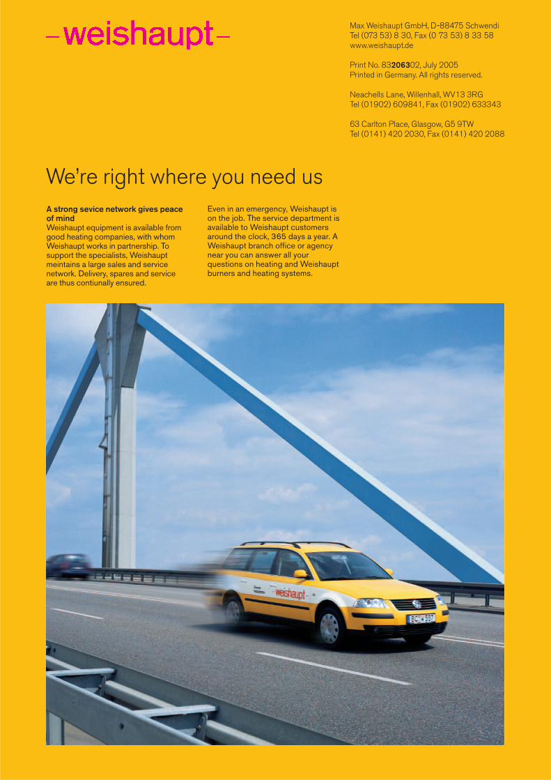
We’re right where you need usA strong sevice network gives peaceof mindWeishaupt equipment is available fromgood heating companies, with whomWeishaupt works in partnership. Tosupport the specialists, Weishauptmeintains a large sales and service network. Delivery, spares and serviceare thus contiunally ensured.
Even in an emergency, Weishaupt ison the job. The service department isavailable to Weishaupt customers around the clock, 365 days a year. AWeishaupt branch office or agencynear you can answer all your questions on heating and Weishauptburners and heating systems.