Embed Size (px)
Citation preview

1
Index/ Instructor’s evaluation of experiment reports S. No.
Name of experiment Date of performance
Experiment marks
Teacher’s Signature
1. To study the forced vibration of the beam for different damping.
2 To determine the radius of gyration ‘k’ of a given compound pendulum.
3 To determine the radius of gyration of
trifilar suspension.
4 To determine the radius of gyration of given bar using bi-filler suspension.
5 To verify the dunker lay’s rule viz.
6 To study the pressure profile of lubricating
conditions of load and speed.
7 To determine the natural frequency of undamped torsional vibration of a single rotor shaft system.
8 To determine the natural frequency of undamped torsional vibration of two rotor shaft system.
9 To determine the frequency of undamped free vibration of an equivalent spring mass system.
10 To determine the frequency of damped force vibration of a spring mass system.
2
EXPERIMENT NO. - 1
Aim: To study the forced vibration of the beam for different damping.
Apparatus used:
Description: In this experiment, a slightly heavy rectangular section bar is supported at both ends
in truinion fittings. Exciter unit with the weight platform can be clamped at any conventional
position along the beam. Exciter unit is connected to the damper. Which provides the necessary
damping?
Damping arrangment:
1. Close the one hole of damper for light damping.
2. Close the two holes of damper for medium damping.
3. Close all the three holes of damper for heavy damping.
Experimental procedure:
1. Arrange the setup
2. Connect the exciter motor to control panel.
3. Start the motor and allow the system to vibrate.
4. Wait for 5 minutes for amplitude to build up for particular forcing frequency.
5. Adjust the position of strip chart recorder. Take the recorder of amplitude vs. Time on
strip chart recorder by starting recorder motor.
6. Take record by changing forcing frequency for each damping.
7. Repeat the experiment for different damping.
Graph:
Plot the graph of amplitude vs. Frequency for each damping
OBSERVATION TABLE:

3
S. No. Forcing frequency Amplitude
1.
2.
3.
PRECAUTIONS:
1. Do not run the motor at low voltage i.e. less than 180 volts.
2. Do not increase the speed at once.
3. Damper is always in perpendicular direction.
4. A motor bolts is properly tightly with weight.
5. A beam is proper tight in bearing with bolt.
6. Always keep the apparatus free from dust.
Result:
Viva-voce:
Experiment No.-2
Aim: To determine the radius of gyration ‘k’ of a given compound pendulum.
Apparatus Used: Compound pendulum test rig.

4
To verify the relation of compound pendulum:-
T=2π√ {k 2+ (og) 2 /g*(og)}
Where
T=periodic time in sec.
K=radius of gyration about c.g. in cm.
Og= distance of c.g. of the rod from support.
L= length of suspended pendulum.
Figure: Compound pendulum
Description:
The compound pendulum consists of a steel bar. The bar is supported by knife edge.
Two pendulums of different lengths are provided with the setup.
Procedure:
1. Support the rod on knife edge.
2. Note the length of suspended pendulum and determine og.
3. Allow the bar to oscillate and determine t by knowing the time for 10 oscillations.
4. Repeat the experiment with different length of suspension.
5. Complete the observation table given bellow.
Formulae:
1. Time period actual
Tactual = t/n sec
2. Actual radius of gyration, kact
Tactual = 2π√ {k act2+ (og) 2 /g*(og)}
3. Theoretical radius of gyration, ktheo

5
Ktheo = l/2√3
Observation & calculation table:
S.no. L cm. Og No. Of
Osc. N
Time
for
Osc.
Tact Kact K theo
1.
2.
3.
Nomenclature: Kact = radius of gyration about cg in cm.
Ktheo = radius of gyration about cg in cm.
L = length of suspended pendulum.
N = no. Of oscillations.
Og = distance of c.g. of the rod from support.
Ttheo = theoretical periodic time in sec.
Tact = actual time period.
T = time required for 10 oscillations.
Result:
Viva-voce:
Experiment No. - 3
Aim: To determine the radius of gyration of trifila r suspension.
Equipments: Trifilar suspension.
Introduction: Trifilar suspension is a disc of mass m (weight w) suspended by three vertical
cords, each of length l, from a fixed support. Each cord is symmetrically attached to the disc at
the same distance r from the mass of the disc.

6
Figure: Trifiller suspension
Theory: the discs is now turned through a small angle its vertical axis, the cords becomes
inclined. One being released the disc will perform oscillations about the vertical axis. At any
instant
Let: ѳ = angular displacement of the disc
F = tension in each cord =w/3
Inertia torque = i × ѳ
Restoring torque = 3 × horizontal component forces of each string × r
Inertia torque = restoring torque
Description: a uniform circular disc is suspended from the pendulum support frame by three
parallel cords. Top ends of the cords pass through the three small chucks fitted at the top. Other
ends aresecuered in the trifieler disc. It is possible to adjust the length of the chord by loosening
the chucks.
Utilities required:
Floor area required: .5 m × .5 m
1. Allow the disc to oscillate about the vertical axis passing through centre
2. Measure the oscillation with time.
3. Repeat the experiment for different lengths & different radius.
Observation & calculation:
S.no. L,m R,m N T,sec

7
T= t/n, sec
F= 1/t , sec-1
K = 1/2πf × ∫gr2/l,
Nomenclature:
R = radius
N = number of oscillation.
T = time for n oscillation, sec.
T = time period of oscillation, sec
F = frequency of oscillation, sec-1
L = length of the cord, m
K = radius of gyration, m
Precautions & maintenance instructions:
1. Tight the drill chucks properly.
2. Length of each cord should be equal.
Experiment No.- 4
AIM: To determine the radius of gyration of given bar using bi-filler suspension.
Apparatus Used: Bifiller suspension rod.
Description: A uniform rectangular section bar is suspended from the pendulum support frame
by two parallel cords. Top ends of the cords pass through the two small chucks fitted at the top.
Other ends are secured in the bi-filler bar. It is possible to adjust the length of the cord by
loosening the chucks.
8
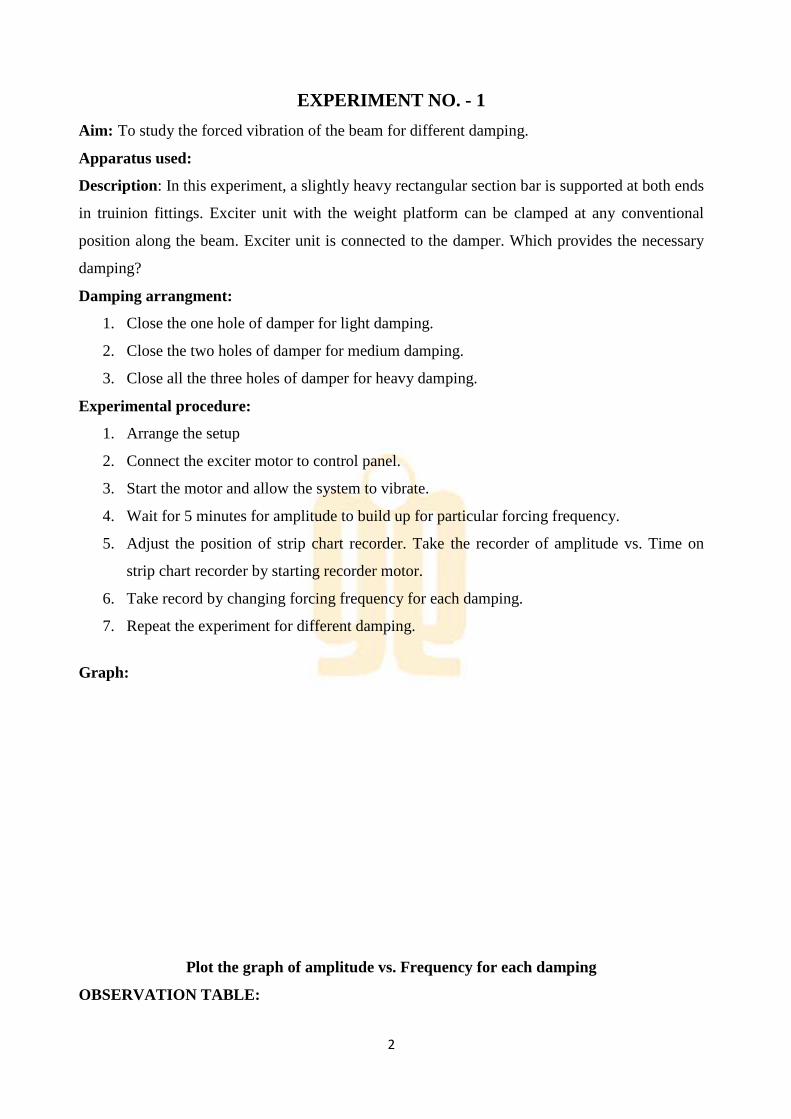
The suspension may be used to determine the radius of gyration of any body. In this case, the
body under investigation is bolted to the center. Radius of gyration of the combined bar and body
is then determined.
Figure: Radius of gyration of bar using bifiller suspension
Experimental procedures:
1 suspend the bar from chuck, and adjust the length of the cord ‘l’ conveniently. Note that the
suspension length of each cord must be same.
2 allow the bar to oscillate the vertical axis passing through the center and measure periodic time
t by knowing the time for say 10 oscillations.
3 Repeat the experiment by mounting the weights at equal distance from center.
4 Complete the observation table below.
Formule:
1 actual time period Tact = t/n sec
2 actual radius of gyration , k act from equation Tact = 2π*kact/a* √l/g
3 theoretical radius of gyration Ktheo = l/2√3
Observation & calculation table:
S . No. L cm A cm No. Of
social
Time for
n social
Tact Kact Ktheo
1
2
Nomenclature:
2a = distance between the two string, g = acceleration due to gravity
Kact= actual radius of gyration of bi- filler suspension
Ktheo= theoretical radius of gyration of bi-filler suspension

9
L = length of suspended string
N = nos. Of oscillation, n = number of oscillations
Result:
Viva-Voce:
Experiment No.-5
Aim: To verify the dunker lay’s rule viz.
Apparatus Used:
1/f2=1/fl2+1/fb
2
Where:-
F=natural frequency of given beam (considering the weight of beam) with central load w.
Fl=natural frequency of given beam (neglecting the weight of beam) with central load w.
Fl=1/2π√ (48e.i.g/l3w)
Fib=natural frequency of the beam.
Description:
At rectangular bar is supported in trunion fitting at each end. Each trunion is provided
In a ball bearing carried in housing. Each bearing housing is fixed to the vertical

10
Frame member. The beam carries a weight platform.
Experimental procedure:
1. Arrange the set-up as shown in fig with some wt. W clamped to wt platform.
2. Pull the platform s release it to set the system in to natural vibration.
3. Find the platform time t s frequency of vibration f by measuring time for some oscillation.
4. Repeat experiment by putting addional masses on weight platform.
5. Plot graph of 1/f2 vs.
Formula:
1. Frequency of beam,
Fl=1/2π√ (48eig/l3w)
2. Natural frequency
Fb=π/2√ (g.e.i/wl4)
3. Moment of inertia of beam section
I=bh3/12
4. Actual time period,
Tact=t/n
5. Actual frequency,
Fact=1/tact
Observation & calculation table:
S no. Wt.
Attached
W kg.
No. Of
Osc n
Time for
N osc. ‘t
Tact=t/n
(sec)
Frequency
Fact.(hz)
Nomancature: B=width of beam
E= modulus of elasticity of beam material
Fl= frequency of beam
Fb= natural frequency of beam
Fact=actual frequency

11
G=acceleration due to gravity..
H=thickness of beam
I=moment of inertia
L=length of the beam
N=number of oscillations
T=time taken for n oscillation
Tact=actual time period
W=weight of beam per unit length
W=central load of the beam, or weight attached.
Result:
Viva-Voce:
Experiment No. - 6
Aim: To study the pressure profile of lubricating conditions of load and speed.
Equipments: Journal bearing apparatus.
Introduction : This apparatus helps to demonstrate and study the effect of important variables
such as speed, viscosity and load, on the pressure distribution in a journal bearing.
The portion of a shaft, which revolves in a bearing and is subjected to load at right angle to the
axis of shaft, known as journal. The whole unit consisting of journal and its supporting part is a
bearing. The whole arrangement is known as journal bearing.
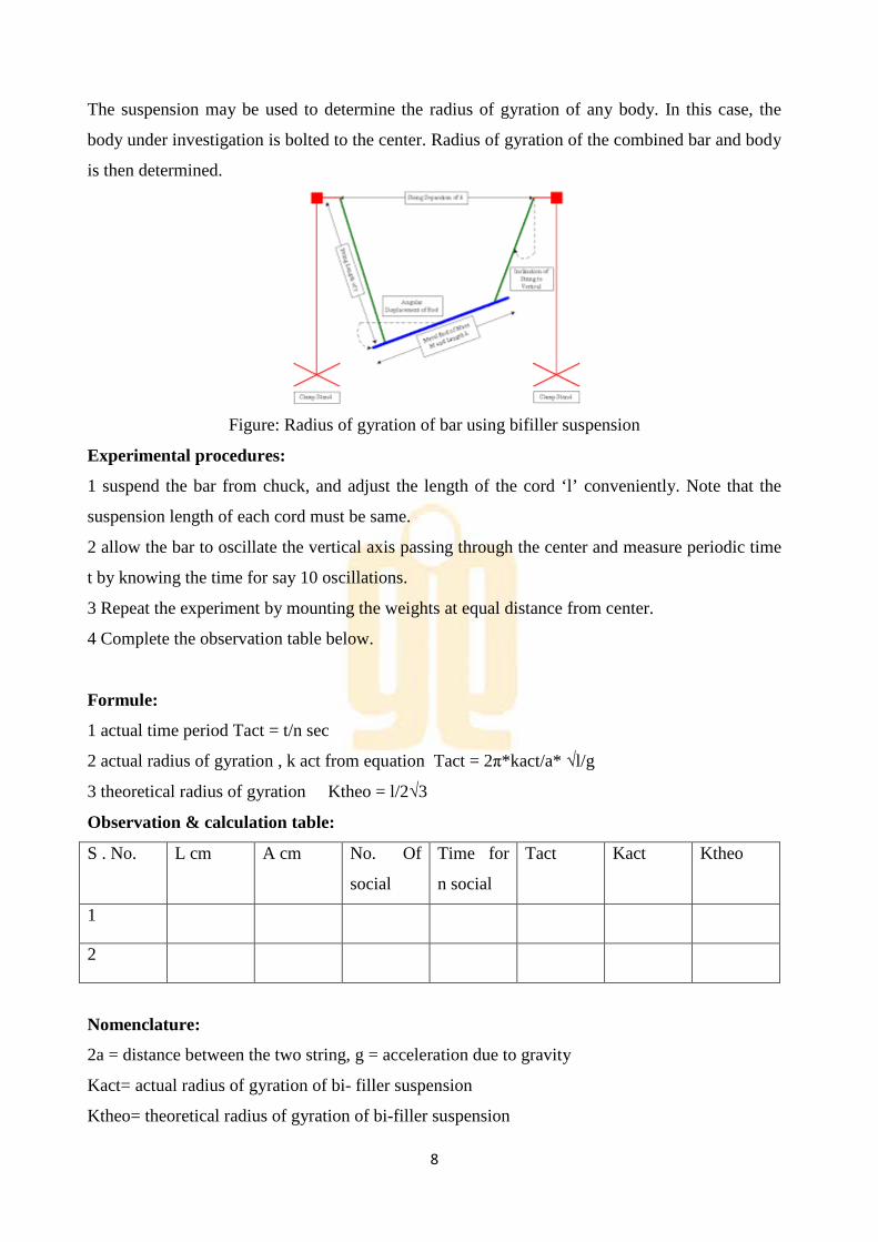
Figure: Pressure profile in journal bearing

12
Theory:
Journal bearing apparatus is designed on the basis of hydrodynamic bearing action used in
practice. In a simple bearing the bearing surface is bored out to a slightly larger diameter than
that of journal. Thus, when the journal is at rest, it makes contact with the bearing surface along a
line, the position of which is determined by the line of action of the external load. If the load is
vertical as in figure the line of contact is parallel to the axis of the journal and the bearing will be
filled with lubricant. When rotation begins the first tendency is for the line of contact to move up
the bearing surface in the opposite direction to that of rotation as shown in figure when the
journal slides over the bearing, the true reaction of the bearing on the journal is inclined to the
normal to the surface at the angle ѳ and this reaction must be in line with the load. The layer of
lubricant immediately adjacent to the journal tends to be carried round with it, but is scrap off by
the bearing, so that a condition of boundary lubrication exists between the high spots on the
journal and bearing surfaces which are actually in contact.
As the speed of rotation of the journal increases, the viscous force which tends to drag the oil
between the surfaces also increases, and more and more of the load is taken by the film in the
convergent space between the journal and bearing. This gradually shifts line of contact round the
bearing in the direction of motion of the journal. Due to this two surfaces are completely
separated and the load is transmitted from the journal of the bearing by the oil. The film will only
break through if it is possible for the resultant oil pressure to be equal to the load, and to have
same line of action. The pressure of the oil in the divergent part of the film may fall below that of
the atmosphere, i witch case air will leak in from the ends of the bearing. Assuming that the
necessary conditions are fulfilled ad that the complete film is formed, the point of nearest
approach of journal to the bearing will by this time have moved to the position shown fig. 1.
Description:
The apparatus consists of a m.s. bearing mounted freely on a steel journal shaft. This journal
shaft is coupled to a d.c. motor. Speed regulator is provided with the setup to control the speed of
journal shaft. The journal bearing has compound pressure gauge measure pressure at different
points. The weight is hanged on the centre of the bearing. On oil inlet mounted on journal to
supply lubricating oil. One valve is also provided to release the trap air.
An oil reservoir accompanies the setup to store the sufficient oil foe experimrnt.this reservoir is
supplies oil to the bearing.
Procedure:
1. Fill 2 lts lubricating oil in feed tank
2. Release the oil from the supply tube and journal with help of ball valve.
13
3. Check that some oil leakage is there for cooling.
4. Set the speed with help of dimmer stat and let the journal run for about 5 min to achieve the
steady state.
5. Add the required loads and keep it horizontal position.
6. Note the rpm of the journal shaft.
7. Note pressure readings at different peripheral positions (after 100 or 150). Rotation of the
journal, with the help compound pressure gauge.
8. After each reading, release pressure and take the next reading.
9. Repeat the experiment for the various speeds and loads.
10. After the test is over set dimmer to zero position and switch off main supply.
Observation & calculation:
Observation:
W2 = ----------kg.
N = -------rpm
Observation table:
S.no. Ѳ P, kg/cm2
Plot of graph b/w ѳ vs. P
Precautions:
1. Never run the apparatus if power supply is less than 180volts and above230volts.
2. Increase the speed gradually.
3. Do not run the journal & bearing with out lubricant oil.
4. Use clean lubricant oil.
5. Always keep the apparatus free from dust.
Result:
Viva-Voce:

14
Experiment No.-7
AIM: To determine the natural frequency of undamped torsional vibration of a single rotor shaft system.
APPARATUS: One disc attaching at one end of the shaft
THEORY: When the particles of the shaft or disc move in a circle about the axis of the shaft, then the
vibrations are known as torsional vibrations. The shaft is twisted and untwisted alternatively and
the torsional shear stresses are induced in the shaft. Since there is no damping in the system these
are undamped vibrations. Also there is no external force is acting on the body after giving an
initial angular displacement then the body is said to be under free or natural vibrations. Hence the
given system is an undamped free torsional vibratory system.
FIGURE:
Figure: Torsional vibration of single rotor
SPECIFICATIONS: Shaft diameter, d = 3 mm Diameter of disc, D = 225 mm Weight of the
disc, W = 2.795 kg Modulus of rigidity for shaft, C = 7.848 * 1010
N/m2
PROCEDURE: 1. Fix the brackets at convinent position along the lower beam. 2. Grip one end of the shaft at the bracket by chuck. 3. Fix the rotor on the other end of the shaft. 4. Twist the rotor through some angle and release. 5. Note down the time required for 10 to 20 oscillations.
6. Repeat the procedure for different length of the shaft.

15
CALCULATIONS:
Polar moment of inertia of shaft = Π * d 4 / 32 Moment of inertia of disc, I = (W/g)*(D
2/8)
1. Torsional stiffness Kt
Kt=(G*Ip)/L
2. Periodic time, T (theoretically)
3. Periodic time, T (expt)
T = t/n 4. Frequency, f (expt) = 1 / T 5. Frequency, f (theo) = / =

16
Sr. No.
Length of shaft, L met
THEORETICAL VALUES
EXPERIMENTAL VALUES
m kg I Tth
fth
No. of oscillations selected, n
Time required for n oscillations, t sec
Texp
=
t/n
fexp
=
n/t
Result:
Viva-voce:

17
THEORY: The system which requires two co-ordinates independently to describe its motion completely is called a two degree of freedom system. The system having two degree of freedom has two natural frequencies. The two rotor system consists of a shaft having torsional stiffness K and two rotors having their inertias as Ii and L? at its two ends. Torsional vibration occurs only when the rotor 1 and rotor 2 rotates in the opposite direction. If the rotor 1 and rotor 2 rotates in the same direction then it has zero frequency. When the rotors rotate in the opposite direction then the amplitude of vibration at the two ends will be in the opposite direction and there exists a point on the shaft having zero amplitude is called node point.
SPECIFICATIONS: Diameter of disc A, DA = 190 mm Diameter of disc B, DB = 225 mm Mass of disc A, m
A = 2.015 kg
Mass of disc B, me = 2.795 kg Mass of arm with bolts, m = 0.166 kg Length of cross arm, R = 0.165 m Diameter of shaft, d = 3 mm
Length of shaft between rotors, L = 1.03 m
Moment of inertia of disc A, IA = kg-m2
Moment of inertia of disc B, IB = kg-m2
Modulus of rigidity of the shaft, C = 7.848 * 1010
N/m2
PROCEDURE: 1. Fix two discs to the shaft and fit the shaft in bearings. 2. Turn the disc in angular position in opposite direction by hand and release.

18
Result:
Viva-Voce:

PROCEDURE: 1. Support one end of the beam in the slot of trunion and clamp it by means of screw. 2. Attach the other end of the beam to the lower end of the spring. 3. Set the beam in the horizontal position. 4. Measure the distance LI of the assembly from pivot. 5. Allow the system to vibrate. 6. Measure the time for say 10 oscillations and find the periodic time and natural •
frequency of vibration. 7. Repeat the experiment by varying L
OBSERVATIONS:
Sr. No.
L1
19
Figure: Free undamped vibration
PROCEDURE: 1. Support one end of the beam in the slot of trunion and clamp it by means of screw. 2. Attach the other end of the beam to the lower end of the spring. 3. Set the beam in the horizontal position. 4. Measure the distance LI of the assembly from pivot. 5. Allow the system to vibrate. 6. Measure the time for say 10 oscillations and find the periodic time and natural •
frequency of vibration. 7. Repeat the experiment by varying L
1.
OBSERVATIONS:
w No of oscillations, n
Time for n oscillations, sec
Figure: Free undamped vibration
1. Support one end of the beam in the slot of trunion and clamp it by means of screw. 2. Attach the other end of the beam to the lower end of the spring.
4. Measure the distance LI of the assembly from pivot.
6. Measure the time for say 10 oscillations and find the periodic time and natural •
Time for
oscillations, sec
Periodic time, T (theo)
Natural frequency fn (theo)
Periodic time, (T = t/n) (expt)
1. Support one end of the beam in the slot of trunion and clamp it by means of screw.
6. Measure the time for say 10 oscillations and find the periodic time and natural •
Periodic time, (T = t/n) (expt)

20
It is to conclude that the theoretical and experimental natural frequency of vibration is almost equal.
Result:
Viva-Voce:

AIM: To determine the frequency of damped force vibration of a spring mass system. APPARATUS: Spring mass system, damper, exciter unit, voltage regulator and striprecorder. THEORY: The vibration that the system executes under damping system is known as damped vibrations. In general all the physical systems are associated with one or the other type of damping. In certain cases amount of damping may be small in other case large. In dama reduction in amplitude over every cycle of vibration. This is due to the fact that a certain amount of energy possessed by the vibrating system is always dissipated in overcoming frictional resistances to the motion. The rate at wupon the type and amount of damping in the system. Damped vibrations can be free vibrations or forced vibrations. Shock absorber is an example of damped vibration. Mainly the following two aspects are important while studying damped free vibrations: 1. The frequency of damped free vibrations and 2. The rate of decay.
FIGURE:
PROCEDURE: 1. Connect the exciter to D.C. motor. 2. Start the motor and allow the system to vibrate. 3. Wait for 3 to 5 minuets for the amplitude to build for particular forcing frequency. 4. Adjust the position of stripchart.
21
Experiment No. – 10
To determine the frequency of damped force vibration of a spring mass system. Spring mass system, damper, exciter unit, voltage regulator and strip
The vibration that the system executes under damping system is known as damped vibrations. In general all the physical systems are associated with one or the other type of damping. In certain cases amount of damping may be small in other case large. In dama reduction in amplitude over every cycle of vibration. This is due to the fact that a certain amount of energy possessed by the vibrating system is always dissipated in overcoming frictional resistances to the motion. The rate at which the amplitude of vibration decays depends upon the type and amount of damping in the system. Damped vibrations can be free vibrations or forced vibrations. Shock absorber is an example of damped vibration. Mainly the following
t while studying damped free vibrations: 1. The frequency of damped free vibrations and
Figure: Damped forced vibration
1. Connect the exciter to D.C. motor. 2. Start the motor and allow the system to vibrate. 3. Wait for 3 to 5 minuets for the amplitude to build for particular forcing frequency. 4. Adjust the position of strip-chart recorder. Take the record of amplitude Vs time on the strip
To determine the frequency of damped force vibration of a spring mass system. Spring mass system, damper, exciter unit, voltage regulator and strip-chart
The vibration that the system executes under damping system is known as damped vibrations. In general all the physical systems are associated with one or the other type of damping. In certain cases amount of damping may be small in other case large. In damped vibrations there is a reduction in amplitude over every cycle of vibration. This is due to the fact that a certain amount of energy possessed by the vibrating system is always dissipated in overcoming
hich the amplitude of vibration decays depends upon the type and amount of damping in the system. Damped vibrations can be free vibrations or forced vibrations. Shock absorber is an example of damped vibration. Mainly the following
3. Wait for 3 to 5 minuets for the amplitude to build for particular forcing frequency. e Vs time on the strip-

22
5. Take record by changing forcing frequency. 6. Repeat the experiment for different damping. Damping can be changed adjusting the position of the exciter. 7. Plot the graph of amplitude Vs frequency for each damping condition.
OBSERVATIONS: Sr. No. Number of oscillations,
n Time required for n oscillations, t
Periodic Time, T
Forcing frequency, f = 1/T
Amplitude, mm
CONCLUSION: 1. From the graph it can be observed that the amplitude of vibration decreases with time. 2. Amplitude of vibration is less with damped system as compared to undamped system. Result: The frequency of damped forced vibration is……… Viva-Voce: