Embed Size (px)
Citation preview

In-line Twin Pump
Installation/Operating ManualOmega DSL

2 / 60
Legal information/CopyrightOriginal operating manual Omega DSL All rights reserved. The contents provided herein must neither be distributed, copied, reproduced, edited or processed forany other purpose, nor otherwise transmitted, published or made available to a third party without the manufacturer'sexpress written consent.Subject to technical modification without prior notice.© Duijvelaar Pompen, Alphen aan den Rijn, Nederland 27/09/2016
3 / 60
ContentsGlossary ............................................................................................................... 6
1 General................................................................................................................. 71.1 Principles ................................................................................................................................................ 71.2 Installation of partly completed machinery.............................................................................................. 71.3 Target group ........................................................................................................................................... 71.4 Other applicable documents ................................................................................................................... 71.5 Symbols .................................................................................................................................................. 8
2 Safety ................................................................................................................... 92.1 Key to safety symbols/markings ............................................................................................................. 92.2 General ................................................................................................................................................... 92.3 Intended use........................................................................................................................................... 92.4 Personnel qualification and training...................................................................................................... 102.5 Consequences and risks caused by non-compliance with this manual................................................ 102.6 Safety awareness ................................................................................................................................. 112.7 Safety information for the operator/user ............................................................................................... 112.8 Safety information for maintenance, inspection and installation........................................................... 112.9 Unauthorised modes of operation......................................................................................................... 112.10 Electromagnetic compatibility ............................................................................................................... 12
3 Transport/Temporary Storage/Disposal ............................................................. 133.1 Checking the condition upon delivery ................................................................................................... 133.2 Transport .............................................................................................................................................. 133.3 Storage/preservation ............................................................................................................................ 133.4 Return to supplier ................................................................................................................................. 143.5 Disposal ................................................................................................................................................ 14
4 Description of the Pump (Set) ............................................................................ 164.1 General description............................................................................................................................... 164.2 Product Information as per Regulation No. 547/2012 (for water pumps with a maximum shaft power of
150 kW) implementing "Ecodesign" Directive 2009/125/EC................................................................. 164.3 Designation........................................................................................................................................... 164.4 Name plate ........................................................................................................................................... 174.5 Design details ....................................................................................................................................... 174.6 Configuration and function.................................................................................................................... 194.7 Noise characteristics............................................................................................................................. 204.8 Scope of supply .................................................................................................................................... 204.9 Dimensions and weight......................................................................................................................... 20
5 Installation at Site ............................................................................................... 215.1 Safety regulations ................................................................................................................................. 215.2 Checks to be carried out prior to installation......................................................................................... 215.3 Installing the pump set.......................................................................................................................... 225.4 Piping.................................................................................................................................................... 22
5.4.1 Connecting the piping .............................................................................................................. 225.4.2 Permissible forces and moments at the pump nozzles............................................................ 235.4.3 Vacuum balance line................................................................................................................ 235.4.4 Auxiliary connections ............................................................................................................... 24
5.5 Enclosure/insulation.............................................................................................................................. 24

4 / 60
5.6 Electrical connection............................................................................................................................. 255.6.1 Motor connection inside the terminal box................................................................................. 25
6 Commissioning/Start-up/Shutdown .................................................................... 286.1 Commissioning/Start-up/Shutdown ...................................................................................................... 28
6.1.1 Prerequisites for commissioning/start-up ................................................................................. 286.1.2 Checking earth conductor connection...................................................................................... 286.1.3 Checking insulation resistance................................................................................................. 286.1.4 Filling in lubricants.................................................................................................................... 296.1.5 Priming and venting the pump ................................................................................................. 296.1.6 Checking the direction of rotation............................................................................................. 306.1.7 Start-up .................................................................................................................................... 306.1.8 Checking the shaft seal ............................................................................................................ 316.1.9 Shutdown ................................................................................................................................. 31
6.2 Operating limits..................................................................................................................................... 326.2.1 Ambient temperature................................................................................................................ 326.2.2 Frequency of starts .................................................................................................................. 326.2.3 Fluid handled............................................................................................................................ 336.2.4 Voltages and frequencies......................................................................................................... 346.2.5 Maximum permissible speed.................................................................................................... 346.2.6 Altitude ..................................................................................................................................... 34
6.3 Shutdown/storage/preservation ............................................................................................................ 346.3.1 Measures to be taken for shutdown ......................................................................................... 34
6.4 Returning to service.............................................................................................................................. 35
7 Servicing/Maintenance ....................................................................................... 367.1 Safety regulations ................................................................................................................................. 367.2 Servicing/inspection.............................................................................................................................. 37
7.2.1 Supervision of operation .......................................................................................................... 377.2.2 Inspection work ........................................................................................................................ 397.2.3 Lubrication and lubricant change ............................................................................................. 39
7.3 Drainage/cleaning................................................................................................................................. 407.4 Dismantling the pump set ..................................................................................................................... 40
7.4.1 General information/Safety regulations.................................................................................... 407.4.2 Preparing the pump set............................................................................................................ 417.4.3 Dismantling the complete pump set ......................................................................................... 417.4.4 Removing the back pull-out unit ............................................................................................... 427.4.5 Removing the impeller ............................................................................................................. 427.4.6 Removing the mechanical seal ................................................................................................ 42
7.5 Reassembling the pump set ................................................................................................................. 427.5.1 General information/Safety regulations.................................................................................... 427.5.2 Fitting the mechanical seal....................................................................................................... 437.5.3 Fitting the impeller .................................................................................................................... 447.5.4 Installing the back pull-out unit ................................................................................................. 44
7.6 Tightening torques................................................................................................................................ 447.7 Spare parts stock.................................................................................................................................. 45
7.7.1 Ordering spare parts ................................................................................................................ 457.7.2 Recommended spare parts stock for 2 years' operation to DIN 24296.................................... 45
8 Trouble-shooting................................................................................................. 46
9 Related Documents ............................................................................................ 489.1 Typical installation positions ................................................................................................................. 489.2 General drawing with list of components .............................................................................................. 50

5 / 60
10 EU Declaration of Conformity ............................................................................. 52
11 EU Declaration of Conformity ............................................................................. 53
12 EU Declaration of Conformity ............................................................................. 54
13 Certificate of Decontamination ........................................................................... 55
Index................................................................................................................... 56
6 / 60
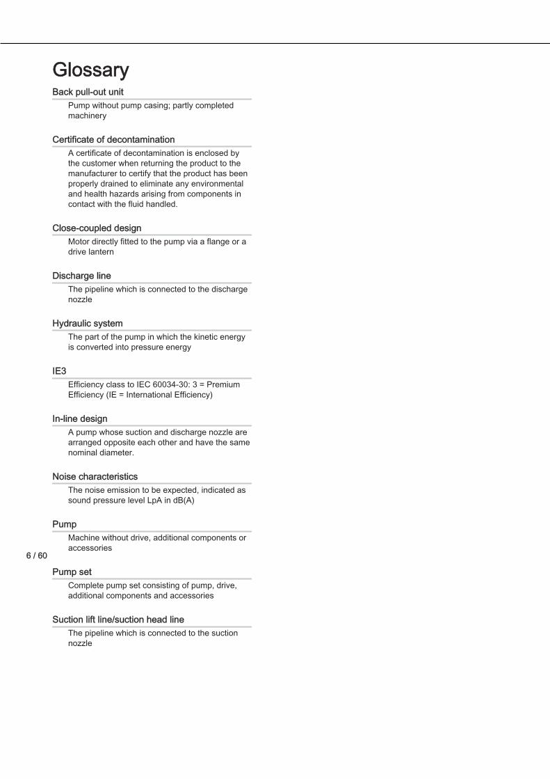
GlossaryBack pull-out unit
Pump without pump casing; partly completedmachinery
Certificate of decontaminationA certificate of decontamination is enclosed bythe customer when returning the product to themanufacturer to certify that the product has beenproperly drained to eliminate any environmentaland health hazards arising from components incontact with the fluid handled.
Close-coupled designMotor directly fitted to the pump via a flange or adrive lantern
Discharge lineThe pipeline which is connected to the dischargenozzle
Hydraulic systemThe part of the pump in which the kinetic energyis converted into pressure energy
IE3Efficiency class to IEC 60034-30: 3 = PremiumEfficiency (IE = International Efficiency)
In-line designA pump whose suction and discharge nozzle arearranged opposite each other and have the samenominal diameter.
Noise characteristicsThe noise emission to be expected, indicated assound pressure level LpA in dB(A)
PumpMachine without drive, additional components oraccessories
Pump setComplete pump set consisting of pump, drive,additional components and accessories
Suction lift line/suction head lineThe pipeline which is connected to the suctionnozzle

7 / 60
General
PrinciplesThis operating manual is supplied as an integral part of the type series indicated on the frontcover. The operating manual describes the proper and safe use of this equipment in allphases of operation.The name plate indicates the type series, the main operating data and the material number/series code. The material number/series code uniquely describes the product and is used asidentification in all further business processes.In the event of damage, immediately contact your nearest DP service centre to maintain theright to claim under warranty. Noise characteristics see [ð Section 4.7, Page 20]
Installation of partly completed machineryTo install partly completed machinery supplied by KSB refer to the sub-sections underServicing/Maintenance.
Target groupThis operating manual is aimed at the target group of trained and qualified specialist technicalpersonnel. [ð Section 2.4, Page 10]
Other applicable documentsTable 1: Overview of other applicable documentsDocument ContentsData sheet Description of the technical data of the pump (set)General arrangement drawing/outlinedrawing
Description of mating dimensions and installationdimensions for the pump (set), weights
Drawing of auxiliary connections Description of auxiliary connectionsHydraulic characteristic curve Characteristic curves showing head, NPSH required,
efficiency and power inputGeneral assembly drawing 1) Sectional drawing of the pumpSub-supplier product literature 1) Operating manuals and other product literature describing
accessories and integrated machinery componentsSpare parts lists 1) Description of spare partsPiping layout 1) Description of auxiliary pipingList of components 1) Description of all pump componentsAssembly drawing 1) Sectional drawing of the installed shaft seal
For accessories and/or integrated machinery components observe the relevantmanufacturer's product literature.
1) If agreed to be included in the scope of supply
1
1.1
1.2
1.3
1.4
8 / 60
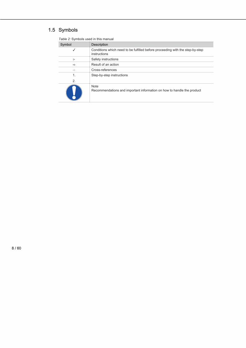
SymbolsTable 2: Symbols used in this manualSymbol Description
✓ Conditions which need to be fulfilled before proceeding with the step-by-stepinstructions
⊳ Safety instructions⇨ Result of an action⇨ Cross-references1.2.
Step-by-step instructions
NoteRecommendations and important information on how to handle the product
1.5

9 / 60
SafetyAll the information contained in this section refers to hazardous situations.
Key to safety symbols/markingsTable 3: Definition of safety symbols/markingsSymbol Description
! DANGER DANGERThis signal word indicates a high-risk hazard which, if not avoided, will result indeath or serious injury.
! WARNING WARNINGThis signal word indicates a medium-risk hazard which, if not avoided, couldresult in death or serious injury.
CAUTION CAUTIONThis signal word indicates a hazard which, if not avoided, could result in damageto the machine and its functions.General hazardIn conjunction with one of the signal words this symbol indicates a hazard whichwill or could result in death or serious injury.
Electrical hazardIn conjunction with one of the signal words this symbol indicates a hazardinvolving electrical voltage and identifies information about protection againstelectrical voltage.Machine damage In conjunction with the signal word CAUTION this symbol indicates a hazard forthe machine and its functions.
GeneralThis operating manual contains general installation, operating and maintenance instructionsthat must be observed to ensure safe pump operation and prevent personal injury anddamage to property.The safety information in all sections of this manual must be complied with.The operating manual must be read and fully understood by the specialist personnel/operators responsible prior to installation and commissioning.The contents of this operating manual must be available to the specialist personnel at the siteat all times.Instructions attached directly to the pump set must always be complied with and kept in aperfectly legible condition. This applies to, e.g.,:
– Arrow indicating the direction of rotation– Markings for connections– Name plate
The operator is responsible for ensuring compliance with all local regulations not taken intoaccount in this operating manual.The electric drive has been designed and constructed in accordance with the requirements ofDirective 2014/35/EU ("Low-voltage Directive").
Intended use– The product must not be used in potentially explosive atmospheres.
2! DANGER
2.1
2.2
2.3

10 / 60
– The pump (set) must only be operated within the operating limits described in the otherapplicable documents.
– Only operate pumps/pump sets which are in perfect technical condition.– Do not operate the pump (set) in partially assembled condition.– Only use the pump to handle the fluids described in the data sheet or product literature of
the pump model or variant.– Never operate the pump without the fluid to be handled.– Observe the minimum flow rates indicated in the data sheet or product literature (to
prevent overheating, bearing damage, etc).– Observe the maximum flow rates indicated in the data sheet or product literature (to
prevent overheating, mechanical seal damage, cavitation damage, bearing damage, etc).– Do not throttle the flow rate on the suction side of the pump (to prevent cavitation
damage).– Consult the manufacturer about any use or mode of operation not described in the data
sheet or product literature.
Prevention of foreseeable misuse– Never open the discharge-side shut-off elements further than permitted.
– The maximum flow rates specified in the product literature or data sheet would beexceeded.
– Risk of cavitation damage– Never exceed the permissible operating limits specified in the data sheet or product
literature regarding pressure, temperature, mains voltage, mains frequency, ambienttemperature, motor rating, speed, etc.
– Observe all safety information and instructions in this manual.
Personnel qualification and trainingAll personnel involved must be fully qualified to transport, install, operate, maintain andinspect the machinery this manual refers to.The responsibilities, competence and supervision of all personnel involved in transport,installation, operation, maintenance and inspection must be clearly defined by the operator.Deficits in knowledge must be rectified by means of training and instruction provided bysufficiently trained specialist personnel. If required, the operator can commission themanufacturer/supplier to train the personnel.Training on the pump (set) must always be supervised by technical specialist personnel.
Consequences and risks caused by non-compliance with this manual– Non-compliance with this operating manual will lead to forfeiture of warranty cover and of
any and all rights to claims for damages.– Non-compliance can, for example, have the following consequences:
– Hazards to persons due to electrical, thermal, mechanical and chemical effects andexplosions
– Failure of important product functions– Failure of prescribed maintenance and servicing practices– Hazard to the environment due to leakage of hazardous substances
2.4
2.5
11 / 60
Safety awarenessIn addition to the safety information contained in this manual and the intended use, thefollowing safety regulations shall be complied with:
– Accident prevention, health and safety regulations– Explosion protection regulations– Safety regulations for handling hazardous substances– Applicable standards, directives and laws
Safety information for the operator/user– The operator shall fit contact guards for hot, cold and moving parts and check that the
guards function properly.– Do not remove any contact guards during operation.– Provide the personnel with protective equipment and make sure it is used.– Contain leakages (e.g. at the shaft seal) of hazardous fluids handled (e.g. explosive,
toxic, hot) so as to avoid any danger to persons and the environment. Adhere to allrelevant laws.
– Eliminate all electrical hazards. (In this respect refer to the applicable national safetyregulations and/or regulations issued by the local energy supply companies.)
– If shutting down the pump does not increase potential risk, fit an emergency-stop controldevice in the immediate vicinity of the pump (set) during pump set installation.
Safety information for maintenance, inspection and installation– Modifications or alterations of the pump are only permitted with the manufacturer's prior
consent.– Use only original spare parts or parts authorised by the manufacturer. The use of other
parts can invalidate any liability of the manufacturer for resulting damage.– The operator ensures that maintenance, inspection and installation is performed by
authorised, qualified specialist personnel who are thoroughly familiar with the manual.– Only carry out work on the pump (set) during standstill of the pump.– Any work on the pump set shall only be performed when it has been disconnected from
the power supply (de-energised).– The pump casing must have cooled down to ambient temperature.– Pump pressure must have been released and the pump must have been drained.– When taking the pump set out of service always adhere to the procedure described in the
manual. [ð Section 6.1.9, Page 31] [ð Section 6.3, Page 34]– Decontaminate pumps which handle fluids posing a health hazard.
[ð Section 7.3, Page 40]– As soon as the work has been completed, re-install and/or re-activate any safety-relevant
and protective devices. Before returning the product to service, observe all instructions oncommissioning.
Unauthorised modes of operationNever operate the pump (set) outside the limits stated in the data sheet and in this manual.The warranty relating to the operating reliability and safety of the supplied pump (set) is onlyvalid if the equipment is used in accordance with its intended use.
2.6
2.7
2.8
2.9

12 / 60
Electromagnetic compatibilityWhen operating the motor on a frequency inverter always observe the frequency invertermanufacturer's information on compliance with the Electromagnetic Compatibility Directive.Take additional measures to ensure compliance with the Directive and obtain a connectionapproval from the local energy supply company, if necessary.
2.10

13 / 60
Transport/Temporary Storage/Disposal
Checking the condition upon delivery1. On transfer of goods, check each packaging unit for damage.2. In the event of in-transit damage, assess the exact damage, document it and notify DP or
the supplying dealer (as applicable) and the insurer about the damage in writingimmediately.
Transport
DANGERThe pump (set) could slip out of the suspension arrangementDanger to life from falling parts!Ø Always transport the pump (set) in the specified position.Ø Never attach the suspension arrangement to the free shaft end or the motor
eyebolt.Ø Give due attention to the weight data and the centre of gravity.Ø Observe the applicable local health and safety regulations.Ø Use suitable, permitted lifting accessories, e.g. self-tightening lifting tongs.
To transport the pump/pump set suspend it from the lifting tackle as shown.
Fig. 1: Transporting the pump set
Storage/preservation
CAUTIONDamage during storage by humidity, dirt or verminCorrosion/contamination of the pump (set)!Ø For short-term outdoor storage cover the pump (set) or the packaged pump
(set) and accessories with waterproof material.
3
3.1
3.2
3.3
14 / 60
CAUTIONWet, contaminated or damaged openings and connectionsLeakage or damage to the pump!Ø Clean and cover pump openings and connections as required prior to
putting the pump into storage.
If commissioning is to take place some time after delivery, we recommend that the followingmeasures be taken for pump (set) storage.
– Store the pump (set) in a dry, protected room where the atmospheric humidity is asconstant as possible.
– Rotate the shaft by hand once a month, e.g. via the motor fan.– Exposed locating surfaces (shaft ends, flange faces, centring spigots, connector
contacts) are treated with a layer of temporary corrosion protection (< 6 months) fortransport. Take suitable corrosion protection measures for extended storage periods.
– Replace closed rolling element bearings after 48 months of storage.If properly stored indoors, the equipment is protected for a maximum of 12 months.New pumps/pump sets are supplied by our factory duly prepared for storage.For storing a pump (set) which has already been operated, observe the measures to be takenfor shutdown. [ð Section 6.3.1, Page 34]
Return to supplier1. Drain the pump as per operating instructions. [ð Section 7.3, Page 40]2. Always flush and clean the pump, particularly if it has been used for handling noxious,
explosive, hot or other hazardous fluids.3. If the pump set has handled fluids whose residues could lead to corrosion damage in the
presence of atmospheric humidity or could ignite upon contact with oxygen, the pump setmust also be neutralised, and anhydrous inert gas must be blown through the pump toensure drying.
4. Always complete and enclose a certificate of decontamination when returning the pump(set).Always indicate any safety and decontamination measures taken.[ð Section 13, Page 55]
NOTEIf required, a blank certificate of decontamination can be downloaded from theKSB web site at: www.ksb.com/certificate_of_decontamination
Disposal
WARNINGFluids, consumables and supplies which are hot and/or pose a healthhazardHazard to persons and the environment!Ø Collect and properly dispose of flushing fluid and any residues of the fluid
handled.Ø Wear safety clothing and a protective mask, if required.Ø Observe all legal regulations on the disposal of fluids posing a health
hazard.
1. Dismantle the pump (set).Collect greases and other lubricants during dismantling.
3.4
3.5

15 / 60
2. Separate and sort the pump materials, e.g. by:- Metals- Plastics- Electronic waste- Greases and other lubricants
3. Dispose of materials in accordance with local regulations or in another controlled manner.

16 / 60
Description of the Pump (Set)
General description– Non-self-priming in-line pump with low-voltage asynchronous motor to IEC 60034
Pump for handling clean or aggressive fluids which are neither chemically nor mechanicallyaggressive to the pump materials.
Product Information as per Regulation No. 547/2012 (for water pumpswith a maximum shaft power of 150 kW) implementing "Ecodesign"Directive 2009/125/EC
– Minimum efficiency index: see name plate, key to name plate– The benchmark for the most efficient water pumps is MEI ≥ 0.70.– Year of construction: see name plate, key to name plate– Manufacturer’s name or trade mark, commercial registration number and place of
manufacture: see data sheet or order documentation– Product’s type and size identificator: see name plate, key to name plate– Hydraulic pump efficiency (%) with trimmed impeller: see data sheet– Pump performance curves, including efficiency characteristics: see documented
characteristic curve– The efficiency of a pump with a trimmed impeller is usually lower than that of a pump with
full impeller diameter. Trimming of the impeller will adapt the pump to a fixed duty point,leading to reduced energy consumption. The minimum efficiency index (MEI) is based onthe full impeller diameter.
– Operation of this water pump with variable duty points may be more efficient andeconomic when controlled, for example, by the use of a variable speed drive thatmatches the pump duty to the system.
– Information on dismantling, recycling and disposal after decommissioning:[ð Section 3.5, Page 14]
– Information on benchmark efficiency or benchmark efficiency graph for MEI = 0.70 (0.40)for the pump based on the model shown in the Figure are available at: http://www.europump.org/efficiencycharts
Designation
Example: OMDL 032-032-080 GG X AV 11 D 2Table 4: Designation keyCode DescriptionOMDL Pump type
OMDL Omega DSL032 Nominal suction nozzle diameter [mm]032 Nominal discharge nozzle diameter [mm]080 Nominal impeller diameter [mm]G Casing material
G Grey cast ironG Impeller material if different from casing material
4
4.1
4.2
4.3

17 / 60
Code DescriptionG Grey cast ironP Polysulphone
X Additional codeX Special design BT3D, BT3
A Casing coverA Conical seal chamber
V Sealing systemV Conical seal chamber with ventA Conical seal chamber
11 Seal code11 Mechanical seal material BQ1EGG
D Scope of supplyD Pump with motor
2 Shaft unit2 SU 123 SU 146 SU 16
Name plate
1
2
3
4
5
6
7
8
910
11
12
dp industriesKalkovenweg 132401 LJ Alphen aan den Rijn
OMDL 032-032-160 GG AV11D2
Omega DSL 01551156 Ø 152 mm
9971234567 000100 / 01
1,0 mm2/s | n 1450 min | 2016
Q 7,50 m3/h l H 6,00 m
η --,-%MEI ≥ 0,40 |
Fig. 2: Name plate (example)
1 Type series code, size and version 2 Type series3 Order No., order item No. and consecutive
No.4 Flow rate
5 Kinematic viscosity of the fluid handled 6 Minimum efficiency index7 Material number (if applicable) 8 Impeller diameter9 Head 10 Speed11 Year of construction 12 Efficiency (see data sheet)
Design details
Design– Close-coupled design/in-line design– Single-stage– Horizontal/vertical installation– Rigid connection between pump and motor
4.4
4.5

18 / 60
Pump casing– Radially split volute casing– In-line design
Impeller type– Closed radial impeller
Shaft seal– KSB mechanical seal
Bearings– Radial ball bearing in the motor housing– Grease lubrication
Drive– Surface-cooled squirrel-cage motor to KSB standard– Efficiency class IE3 to IEC 60034-30 (≥ 0.75 kW)– Winding 50 Hz, 1~220-240 V / 3~380-420 V ≤ 1.10 kW– Winding 50 Hz, 3~380-420 V ≥ 1.80 kW– Type of construction IM V1– IP55 enclosure– Mode of operation: continuous operation S1– Thermal class F
AutomationAutomation options:
– PumpDrive
19 / 60
Configuration and function
3
4
11
9
7
6
10
1
5
8
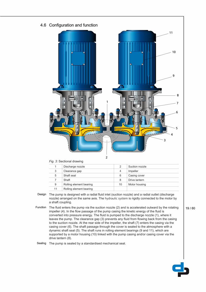
2Fig. 3: Sectional drawing
1 Discharge nozzle 2 Suction nozzle3 Clearance gap 4 Impeller5 Shaft seal 6 Casing cover7 Shaft 8 Drive lantern9 Rolling element bearing 10 Motor housing11 Rolling element bearing
The pump is designed with a radial fluid inlet (suction nozzle) and a radial outlet (dischargenozzle) arranged on the same axis. The hydraulic system is rigidly connected to the motor bya shaft coupling.The fluid enters the pump via the suction nozzle (2) and is accelerated outward by the rotatingimpeller (4). In the flow passage of the pump casing the kinetic energy of the fluid isconverted into pressure energy. The fluid is pumped to the discharge nozzle (1), where itleaves the pump. The clearance gap (3) prevents any fluid from flowing back from the casingto the suction nozzle. At the rear side of the impeller, the shaft (7) enters the casing via thecasing cover (6). The shaft passage through the cover is sealed to the atmosphere with adynamic shaft seal (5). The shaft runs in rolling element bearings (9 and 11), which aresupported by a motor housing (10) linked with the pump casing and/or casing cover via thedrive lantern (8).The pump is sealed by a standardised mechanical seal.
4.6
Design
Function
Sealing

20 / 60
Noise characteristicsTable 5: Surface sound pressure level LpA
2) 3)
Rated power input PN Pump set[kW] 1450 rpm 2900 rpm0,12 36 400,18 36 400,25 - 460,37 36 460,55 - 460,75 37 521,1 - 521,8 - 533 - 53
2) Spatial average; as per ISO 3744 and EN 12639; valid for pump operation in the Q/Qopt = 0.8 - 1.1 range and fornon-cavitating operation. If noise levels are to be guaranteed: Add +3 dB for measuring and constructional tolerance.
3) Increase for 60 Hz operation: 3500 rpm +3 dB; 1750 rpm +1 dB
Scope of supplyDepending on the model, the following items are included in the scope of supply:
– Pump setor
– Motor incl. casing cover
Accessories– Pump foot for vertical installation of the drive
Dimensions and weightFor dimensions and weights please refer to the type series booklet of the pump.
4.7
4.8
4.9

21 / 60
Installation at Site
Safety regulations
DANGERImproper installation in potentially explosive atmospheresDamage to the pump set!Ø Comply with the applicable local explosion protection regulations.Ø Observe the information given in the data sheet and on the pump/motor
name plates.
Checks to be carried out prior to installationCheck the structural requirements. All structural work required must have been prepared in accordance with the dimensionsstated in the outline drawing/general arrangement drawing.
CAUTIONIngress of leakage into the motorDamage to the pump!Ø Never install the pump set with the "motor below".
Protective roof/additional roofingFor vertical installation with the motor on top, fit a protective roof or additional roofing toprevent foreign objects from falling into the fan hood.
Ventilation
WARNINGImproper installationDrive overheated!Ø Maintain the specified minimum distances to neighbouring assemblies.Ø Never restrict the ventilation ducting to/from the drive.Ø Prevent exhaust air from neighbouring assemblies from being drawn in
directly.
X
Fig. 4: Minimum distance X
Table 6: Minimum distance X to neighbouring assembliesMotors with shaft centreline height [mm] Minimum distance X [mm]
71 - 100 30
5
5.1
5.2Foundation
Protective roof
Ventilation

22 / 60
Installing the pump set
CAUTIONIngress of leakage into the motorDamage to the pump!Ø Never install the pump set with the "motor below".
The pump set may be flanged directly into the piping.1. Position the pump set on the foundation or in the piping and fasten it.2. Place a spirit level on the discharge nozzle to align the pump set.
Piping
Connecting the piping
DANGERImpermissible loads acting on the pump nozzlesDanger to life from leakage of hot, toxic, corrosive or flammable fluids!Ø Do not use the pump as an anchorage point for the piping.Ø Anchor the pipes in close proximity to the pump and connect them without
transmitting any stresses or strains.Ø Observe the permissible forces and moments at the pump nozzles.
[ð Section 5.4.2, Page 23]Ø Take appropriate measures to compensate for thermal expansion of the
piping.
CAUTIONIncorrect earthing during welding work at the pipingDestruction of rolling element bearings (pitting effect)!Ø Never earth the electric welding equipment on the pump or baseplate.Ø Prevent current flowing through the rolling element bearings.
NOTEInstalling check and shut-off elements in the system is recommended,depending on the type of plant and pump. However, such elements must notobstruct proper drainage or hinder disassembly of the pump.
ü Suction lift lines have been laid with a rising slope, suction head lines with a downwardslope towards the pump.
ü A flow stabilisation section having a length equivalent to at least twice the diameter of thesuction flange has been provided upstream of the suction flange.
ü The nominal diameters of the pipelines are at least equal to the nominal diameters of thepump nozzles.
ü Adapters to larger diameters have a diffuser angle of approximately 8° to preventexcessive pressure losses.
ü The pipelines have been anchored in close proximity to the pump and connected withouttransmitting any stresses or strains.
1. Thoroughly clean, flush and blow through all vessels, pipelines and connections(especially of new installations).
5.3
5.4
5.4.1

23 / 60
2. Before installing the pump in the piping, remove the flange covers on the suction anddischarge nozzles of the pump.
3. Check that the inside of the pump is free from any foreign objects. Remove any foreignobjects.
4. If required, install a filter in the piping (see figure: Filter in the piping).1
2Fig. 5: Filter in the piping
1 Differential pressure gauge 2 Filter
5. Connect the pump nozzles to the piping.
CAUTIONAggressive flushing and pickling agentsDamage to the pump!Ø Match the cleaning operation mode and duration for flushing and pickling
service to the casing and seal materials used.
Permissible forces and moments at the pump nozzlesNo piping-induced forces and moments (from warped pipelines or thermal expansion, forexample) must act on the pump.
Vacuum balance line
NOTEWhere fluid has to be pumped out of a vessel under vacuum, installing avacuum balance line is recommended.
The following rules apply to vacuum balance lines:– Minimum nominal line diameter 25 mm.– The line extends above the highest permissible fluid level in the vessel.
5.4.2
5.4.3

24 / 60
1 2
5
43
6Fig. 6: Vacuum balance system
1 Vessel under vacuum 2 Vacuum balance line3 Shut-off element 4 Swing check valve5 Main shut-off element 6 Vacuum-tight shut-off element
NOTEAn additional line fitted with a shut-off valve (from the pump discharge nozzle tothe balance line) facilitates venting of the pump before start-up.
Auxiliary connections
WARNINGFailure to use or incorrect use of auxiliary connections (e.g. barrier fluid,flushing liquid, etc.)Risk of injury from escaping fluid!Risk of burns!Malfunction of the pump!Ø Refer to the general arrangement drawing, the piping layout and pump
markings (if any) for the quantity, dimensions and locations of auxiliaryconnections.
Ø Use the auxiliary connections provided.
Enclosure/insulation
WARNINGThe volute casing and casing/discharge cover take on the sametemperature as the fluid handledRisk of burns!Ø Insulate the volute casing.Ø Fit protective equipment.
5.4.4
5.5

25 / 60
CAUTIONRisk of potentially explosive atmosphere due to insufficient ventilationExplosion hazard!Ø Make sure the space between the casing cover/discharge cover and the
bearing cover is sufficiently vented.
CAUTIONHeat build-up in the bearing bracketDamage to the bearing!Ø Never insulate the bearing bracket, bearing bracket lantern and casing
cover.
Electrical connection
DANGERHazardous voltageDanger of death from electric shock!Ø Have all work performed only by qualified specialist personnel and only
when the drive is at a standstill and secured against unintentional start-up.This also applies to auxiliary circuits (e.g. standstill heater).
Ø The drive must not be electrically connected at any point in time when workis performed on the open terminal box.
WARNINGIncorrect connection to the mainsDamage to the mains network, short circuit!Ø Observe the technical specifications of the local energy supply companies.
NOTEAlways protect three-phase motors with a current-dependent overload protectiondevice with additional phase failure protection.
Select the motor connection cables in accordance with IEC 60364, taking into account thecurrent load of the cable at the given ambient temperature and the requisite heat dissipationto IEC / EN 60204-1 as a result of cable routing.
Motor connection inside the terminal boxObserve the following when performing any work on the terminal box:
– Always use the original sealing element to close the terminal box so that it is dust- andwatertight.
– Do not damage components on the inside of the terminal box (e.g. terminal board andcable connections).
– Ensure that no foreign bodies, contamination or moisture are present in the terminal box.Terminal box cable entries to DIN 42925.
– Close additional open cable entries, fitting O-rings or suitable gaskets.– Observe prescribed tightening torques for cable glands and other screws/bolts.– When retrofitting cable glands to safeguard the required level of enclosure protection,
ensure that the gasket is seated properly on the outside of the terminal box.
5.6
5.6.1

26 / 60
Connecting the motor1. Check the voltage of the available power supply network against the data on the motor
name plate.2. Knock out any knock-out openings in the terminal box. While doing this, avoid causing
damage to the terminal board, cable connections, etc. inside the terminal box.3. Connect the motor in star or delta configuration in accordance with the rated voltage (see
name plate) and the available power supply network.
N L
1~, configurationTo connect a single-phase motor to the AC power grid, connect the phase conductor toterminal "L" and neutral to terminal "N".
U1 V1 W1
U2 V2W2
PE
3~, star configuration
U1 V1 W1
U2 V2W2
PE
3~, delta configuration4. Connect the earth conductor (PE).
Tightening torques
Unless other tightening torques are indicated on the motor the following torques shall beused:
5.6.1.1

27 / 60
Table 7: Tightening torques Thread Tightening torque
[Nm]M4 1,2M5 2,0M6 3,0M8 6,0M10 10,0

28 / 60
Commissioning/Start-up/Shutdown
Commissioning/Start-up/Shutdown
DANGERHazardous voltageDanger of death from electric shock!Ø Have all work performed only by qualified specialist personnel and only
when the drive is at a standstill and secured against unintentional start-up.This also applies to auxiliary circuits (e.g. standstill heater).
Ø The drive must not be electrically connected at any point in time when workis performed on the open terminal box.
Before commissioning and whenever returning the product to service, perform the electricalsafety checks stipulated by EN 60204-1.
Prerequisites for commissioning/start-upBefore commissioning/starting up the pump set, make sure that the following conditions aremet:
– The drive has been mounted and aligned correctly.– The operating conditions have been verified against the name plate data.– The earth connection and potential equalisation connections have been made correctly.– All fastening bolts/screws, connecting elements and electrical connections have been
tightened to the specified tightening torques.– Measures have been taken to prevent accidental contact with moving and live parts.– Components (cables, etc.) that are sensitive to temperature do not come into contact with
the motor housing.– The pump set has been properly connected to the power supply and is equipped with all
protection devices.– The pump has been primed with the fluid to be handled. The pump has been vented.– The direction of rotation has been checked.– All auxiliary connections required are connected and operational.– After prolonged shutdown of the pump (set), the activities required for returning the pump
(set) to service have been carried out. [ð Section 6.4, Page 35]
Checking earth conductor connectionCheck that the earth conductor has been correctly connected in accordance with EN 60204.
Checking insulation resistancePrior to commissioning and following prolonged storage or standstill periods, the insulationresistance will need to be checked and verified.
6
6.1
6.1.1
6.1.2
6.1.3
29 / 60
NOTEIf windings have been dried after having been repaired or cleaned, bear in mindthat the insulation resistance of warm windings is lower. The insulationresistance can only be correctly evaluated after converting to the referencetemperature of 25 °C.
The insulation resistance of the stator winding must equal at least 1.5 megohms in motors for220 -1000 V.
Filling in lubricantsGrease-lubricated bearings have been packed with grease at the factory.
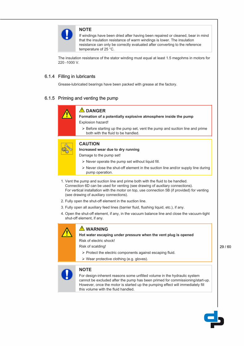
Priming and venting the pump
DANGERFormation of a potentially explosive atmosphere inside the pumpExplosion hazard!Ø Before starting up the pump set, vent the pump and suction line and prime
both with the fluid to be handled.
CAUTIONIncreased wear due to dry runningDamage to the pump set!Ø Never operate the pump set without liquid fill.Ø Never close the shut-off element in the suction line and/or supply line during
pump operation.
1. Vent the pump and suction line and prime both with the fluid to be handled.Connection 6D can be used for venting (see drawing of auxiliary connections).For vertical installation with the motor on top, use connection 5B (if provided) for venting(see drawing of auxiliary connections).
2. Fully open the shut-off element in the suction line.3. Fully open all auxiliary feed lines (barrier fluid, flushing liquid, etc.), if any.4. Open the shut-off element, if any, in the vacuum balance line and close the vacuum-tight
shut-off element, if any.
WARNINGHot water escaping under pressure when the vent plug is openedRisk of electric shock!Risk of scalding!Ø Protect the electric components against escaping fluid.Ø Wear protective clothing (e.g. gloves).
NOTEFor design-inherent reasons some unfilled volume in the hydraulic systemcannot be excluded after the pump has been primed for commissioning/start-up.However, once the motor is started up the pumping effect will immediately fillthis volume with the fluid handled.
6.1.4
6.1.5

30 / 60
Checking the direction of rotation
DANGERTemperature increase resulting from contact between rotating andstationary componentsDamage to the pump set!Ø Never check the direction of rotation by starting up the unfilled pump set.
WARNINGHands inside the pump casingRisk of injuries, damage to the pump!Ø Always disconnect the pump set from the power supply and secure it
against unintentional start-up before inserting your hands or other objectsinto the pump.
WARNINGParts flying offPersonal injury and damage to property!Ø When checking the direction of rotation with the coupling removed, secure
the respective keys to protect them from being thrown off.
CAUTIONDrive and pump running in the wrong direction of rotationDamage to the pump!Ø Refer to the arrow indicating the direction of rotation on the pump.Ø Check the direction of rotation. If required, check the electrical connection
and correct the direction of rotation.
The correct direction of rotation of the motor and pump is clockwise (seen from the motorend).
1. Start the motor and stop it again immediately to determine the motor's direction ofrotation.
2. Check the direction of rotation. The motor's direction of rotation must match the arrow indicating the direction of rotationon the pump.
3. If the motor is running in the wrong direction of rotation, check the electrical connection ofthe motor and the control system, if any.
Start-up
DANGERNon-compliance with the permissible pressure and temperature limits ifthe pump is operated with the suction and discharge lines closed.Leakage of hot or toxic fluids!Ø Never operate the pump with the shut-off elements in the suction line and/or
discharge line closed.Ø Only start up the pump set with the discharge-side gate valve slightly or fully
open.
6.1.6
6.1.7
31 / 60
DANGERExcessive temperatures due to dry running or excessive gas content in thefluid handledDamage to the pump set!Ø Never operate the pump set without a liquid fill.Ø Prime the pump as per operating instructions.Ø Always operate the pump within the permissible operating range.
CAUTIONAbnormal noises, vibrations, temperatures or leakageDamage to the pump!Ø Switch off the pump (set) immediately.Ø Eliminate the causes before returning the pump set to service.
ü The system piping has been cleaned.ü Pump, suction line and inlet tank, if fitted, have been vented and primed with the fluid to
be handled.ü The lines for priming and venting have been closed.1. Fully open the shut-off element in the suction head line/suction lift line.2. Close or slightly open the shut-off element in the discharge line.3. Start up the motor.4. Immediately after the pump has reached full rotational speed, slowly open the shut-off
element in the discharge line and adjust it to comply with the duty point.
Checking the shaft sealThe mechanical seal only leaks slightly or invisibly (as vapour) during operation.Mechanical seals are maintenance-free.
Shutdown
CAUTIONHeat build-up inside the pumpDamage to the shaft seal!Ø Depending on the type of installation, the pump set requires sufficient after-
run time – with the heat source switched off – until the fluid handled hascooled down.
ü The shut-off element in the suction line is and remains open.1. Close the shut-off element in the discharge line.2. Switch off the motor and make sure the pump set runs down smoothly to a standstill.
NOTEIf the discharge line is equipped with a check valve, the shut-off element in thedischarge line may remain open, provided the site's requirements andregulations are taken into account and observed.
For prolonged shutdown periods:1. Close the shut-off element in the suction line.
6.1.8Mechanical seal
6.1.9
32 / 60
2. Close the auxiliary connections. If the fluid handled is fed in under vacuum, also supply the shaft seal with barrier fluidduring standstill.
CAUTIONRisk of freezing during prolonged pump shutdown periodsDamage to the pump!Ø Drain the pump and the cooling/heating chambers (if any) or otherwise
protect them against freezing.
Operating limits
DANGERNon-compliance with operating limits for pressure, temperature and speedExplosion hazard!Leakage of hot or toxic fluid handled!Ø Comply with the operating data indicated in the data sheet.Ø Never use the pump to handle fluids it is not designed for.Ø Avoid prolonged operation against a closed shut-off element.Ø Never operate the pump at temperatures exceeding those specified in the
data sheet or on the name plate unless the written consent of themanufacturer has been obtained.
Ambient temperature
CAUTIONOperation outside the permissible ambient temperatureDamage to the pump (set)!Ø Observe the specified limits for permissible ambient temperatures.
Observe the following parameters and values during operation:
Table 8: Permissible ambient temperaturesPermissible ambient temperature ValueMaximum 40 °CMinimum See data sheet.
Frequency of starts
DANGERExcessive surface temperatures of the motorExplosion hazard!Ø The limit value for stopping the pump must never exceed the specified
surface temperature of the respective temperature class.Ø If the specified surface temperature of the respective temperature class is
exceeded, immediately switch off the pump set and determine the cause.
6.2
6.2.1
6.2.2

33 / 60
The frequency of starts is usually determined by the maximum temperature increase of themotor. This largely depends on the power reserves of the motor in steady-state operation andon the starting conditions (DOL, star-delta, moments of inertia, etc). If the start-ups are evenlyspaced over the period indicated, the following limits serve as orientation for start-up with thedischarge-side gate valve slightly open:
Table 9: Frequency of startsMaterial Maximum frequency of starts
[Start-ups/hour]G (EN-GJL-150) 15B (G-CuSn10Zn) 6P (PSu-GF30) 6
CAUTIONRe-starting while motor is still running downDamage to the pump (set)!Ø Do not re-start the pump set before the pump rotor has come to a standstill.
Fluid handled
Flow rate
Table 10: Flow rateTemperature range (t) Minimum flow rate Maximum flow rate-30 to +70 ℃ ≈ 15 % of QOpt
4) See hydraulic characteristiccurves> 70 to +140 °C ≈ 25 % of QOpt
4)
The calculation formula below can be used to check if an additional heat build-up could leadto a dangerous temperature increase at the pump surface.
××
×
Table 11: KeySymbol Description Unit
c Specific heat capacity J/kg Kg Gravitational constant m/s²H Pump discharge head mTf Fluid temperature °CTO Temperature at the casing surface °C
Pump efficiency at duty point -Temperature difference K
4) Best efficiency point
Density of the fluid handled
The pump input power changes in proportion to the density of the fluid handled.
6.2.3
6.2.3.1
6.2.3.2
34 / 60
CAUTIONImpermissibly high density of the fluid handledMotor overload!Ø Observe the information on fluid density in the data sheet.Ø Make sure the motor has sufficient power reserves.
Abrasive fluids
Do not exceed the maximum permissible solids content specified in the data sheet.When the pump handles fluids containing abrasive substances, increased wear of thehydraulic system and shaft seal are to be expected. In this case, reduce the commonlyrecommended inspection intervals.
Voltages and frequenciesMotor operation off the rated point will cause a rise in motor temperature. A voltage toleranceof ± 5 % and a frequency tolerance of ± 2 % are permissible.Any situation where both the voltage and the frequency tolerance apply simultaneously shallbe governed by the provisions of range A as described in EN 60034-1. The motors can beoperated continuously in range A. In accordance with EN 60034-1, prolonged operation inrange B is not recommended.
Maximum permissible speedComply with the rotational speed indicated on the name plate.
Altitude– ≤ 1000 m above MSL: without power derating– > 1000 m above MSL: installation at altitudes of up to 4000 m above MSL is possible with
power derated by 3.8 % per 500 m.
Shutdown/storage/preservation
Measures to be taken for shutdown
The pump (set) remains installedü Sufficient fluid is supplied for the operation check run of the pump.1. Start up the pump (set) regularly between once a month and once every three months for
approximately five minutes during prolonged shutdown periods. This will prevent the formation of deposits within the pump and the pump intake area.
The pump (set) is removed from the pipe and storedü The pump has been properly drained [ð Section 7.3, Page 40] and the safety
instructions for dismantling the pump have been observed.1. Spray-coat the inside wall of the pump casing and, in particular, the impeller clearance
areas with a preservative.2. Spray the preservative through the suction and discharge nozzles.
It is advisable to then close the pump nozzles (e.g. with plastic caps or similar).
6.2.3.3
6.2.4
6.2.5
6.2.6
6.3
6.3.1

35 / 60
3. Oil or grease all exposed machined parts and surfaces of the pump (with silicone-free oiland grease, food-approved if required) to protect them against corrosion.Observe the additional instructions .
If the pump set is to be stored temporarily, only preserve the wetted components made oflow-alloy materials. Commercially available preservatives can be used for this purpose.Observe the manufacturer's instructions for application/removal.Observe any additional instructions and information provided. [ð Section 3, Page 13]
Returning to serviceFor returning the pump to service, observe the sections on commissioning/start-up and theoperating limits .In addition, carry out all servicing/maintenance operations before returning the pump (set) toservice. [ð Section 7, Page 36]
WARNINGFailure to re-install or re-activate protective devicesRisk of personal injury from moving parts or escaping fluid!Ø As soon as the work is complete, re-install and/or re-activate any safety-
relevant and protective devices.
NOTEIf the pump has been out of service for more than one year, replace allelastomer seals.
6.4

36 / 60
Servicing/Maintenance
Safety regulations
DANGERSparks produced during servicing workExplosion hazard!Ø Observe the safety regulations in force at the place of installation!Ø Never open an energised pump set.Ø Always perform maintenance work on pump sets outside potentially
explosive atmospheres only.
DANGERImproperly serviced pump setExplosion hazard!Damage to the pump set!Ø Service the pump set regularly.Ø Prepare a maintenance schedule with special emphasis on lubricants, shaft
seal and coupling.
The operator ensures that maintenance, inspection and installation is performed byauthorised, qualified specialist personnel who are thoroughly familiar with the manual.
WARNINGUnintentional starting of the pump setRisk of injury by moving components and shock currents!Ø Ensure that the pump set cannot be switched on unintentionally.Ø Always make sure the electrical connections are disconnected before
carrying out work on the pump set.
WARNINGFluids, consumables and supplies which are hot and/or pose a healthhazardRisk of injury!Ø Observe all relevant laws.Ø When draining the fluid take appropriate measures to protect persons and
the environment.Ø Decontaminate pumps which handle fluids posing a health hazard.
WARNINGInsufficient stabilityRisk of crushing hands and feet!Ø During assembly/dismantling, secure the pump (set)/pump parts to prevent
tipping or falling over.
A regular maintenance schedule will help avoid expensive repairs and contribute to trouble-free, reliable operation of the pump, pump set and pump parts with a minimum of servicing/maintenance expenditure and work.
7
7.1

37 / 60
NOTEAll maintenance, service and installation work can be carried out by DP Serviceor authorised workshops.
Never use force when dismantling and reassembling the pump set.
Servicing/inspection
Supervision of operation
DANGERRotating or live partsDeath, serious injury or damage to property!Ø If covers have to be removed, de-energise the motor beforehand.Ø Avoid touching live or rotating parts.
DANGERIncorrectly serviced shaft sealFire hazard!Leakage of hot fluids!Damage to the pump set!Ø Regularly service the shaft seal.
DANGERExcessive temperatures as a result of bearings running hot or defectivebearing sealsFire hazard!Damage to the pump set!Ø Regularly check the rolling element bearings for running noises.
DANGERHot surfaceRisk of burns!Ø Never touch a motor when it is in operation.Ø Let the motor cool down.Ø Only remove covers if indicated.
WARNINGCondensing air humidity inside the motor if the motor and/or ambienttemperatures frequently changeRisk of corrosion by condensation!Ø Always observe the information provided on ambient conditions.
7.2
7.2.1

38 / 60
CAUTIONImpermissibly high temperature of fluid handledDamage to the pump!Ø Prolonged operation against a closed shut-off element is not permitted
(heating up of the fluid).Ø Observe the temperature limits in the data sheet and in the section on
operating limits.
CAUTIONIncreased wear due to dry runningDamage to the pump set!Ø Never operate the pump set without liquid fill.Ø Never close the shut-off element in the suction line and/or supply line during
pump operation.
While the pump is in operation, observe and check the following:– The pump must run quietly and free from vibrations at all times.– Check the shaft seal. [ð Section 6.1.8, Page 31]– Check the static sealing elements for leakage.– Check the rolling element bearings for running noises.
Vibrations, noise and an increase in current input occurring during unchanged operatingconditions indicate wear.
– Monitor the correct functioning of any auxiliary connections.– Monitor the stand-by pump.
To make sure that stand-by pumps are ready for operation, start them up once a week.– Monitor the bearing temperature.
The bearing temperature must not exceed 90 °C (measured on the motor housing).– Deviations from normal operation such as increased power consumption, temperatures or
vibrations, unusual noises or odours, tripping of monitoring devices, etc.
CAUTIONOperation outside the permissible bearing temperatureDamage to the pump!Ø The bearing temperature of the pump (set) must never exceed 90 °C
(measured on the outside of the motor housing).
NOTEAfter commissioning, increased temperatures may occur at grease-lubricatedrolling element bearings due to the running-in process. The final bearingtemperature is only reached after a certain period of operation (up to 48 hoursdepending on the conditions).

39 / 60
Inspection work
DANGERExcessive temperatures caused by friction, impact or frictional sparksFire hazard!Damage to the pump set!Ø Regularly check the cover plates, plastic components and other guards of
rotating parts for deformation and sufficient distance from rotating parts.
Cleaning filters
CAUTIONInsufficient inlet pressure due to clogged filter in the suction lineDamage to the pump!Ø Monitor contamination of filter with suitable means (e.g. differential pressure
gauge).Ø Clean filter at appropriate intervals.
Checking the motor
Carry out the following measures:– Check that the electrical connections are firmly seated.– Verify that ventilation paths are unobstructed and clean.– Check that the terminal box is closed safely.
Lubrication and lubricant change
Maintenance of rolling element bearings
Extended storage periods decrease the service life of the lubricating grease. This in turnreduces the service life of the bearings.
– The rolling element bearings should be completely replaced after a storage period ofmore than 4 years.
Recommended bearing replacement interval under normal operating conditions:
Table 12: Bearing replacementAmbient temperature Bearing replacement interval40 °C 20.000 h
NOTEThe bearing service life is reduced e.g. for vertical installations, high vibrationand shock loads, frequent reversing duty, higher ambient temperature andhigher rotating speeds.
Grease lubrication
The bearings are supplied packed with high-quality lithium-soap grease.
7.2.2
7.2.2.1
7.2.2.2
7.2.3
7.2.3.1Maintenance for
long-term storage
Maintenance fornormal operating
conditions
7.2.3.1.1

40 / 60
Intervals
The rolling element bearings of the motor are grease-packed and maintenance-free.
Drainage/cleaning
WARNINGFluids, consumables and supplies which are hot and/or pose a healthhazardHazard to persons and the environment!Ø Collect and properly dispose of flushing fluid and any residues of the fluid
handled.Ø Wear safety clothing and a protective mask, if required.Ø Observe all legal regulations on the disposal of fluids posing a health
hazard.
1. Use connection 6B to drain the fluid handled (see auxiliary connections).2. Always flush the pump if it has been used for handling noxious, explosive, hot or other
hazardous fluids.Always flush and clean the pump before transporting it to the workshop. Provide acertificate of decontamination for the pump.
Dismantling the pump set
General information/Safety regulations
DANGERInsufficient preparation of work on the pump (set)Risk of injury!Ø Properly shut down the pump set. [ð Section 6.1.9, Page 31]Ø Close the shut-off elements in suction and discharge line.Ø Drain the pump and release the pump pressure. [ð Section 7.3, Page 40]Ø Close any auxiliary connections.Ø Allow the pump set to cool down to ambient temperature.
WARNINGUnqualified personnel performing work on the pump (set)Risk of injury!Ø Always have repair and maintenance work performed by specially trained,
qualified personnel.
DANGERHot surfaceRisk of burns!Ø Never touch a motor when it is in operation.Ø Let the motor cool down.Ø Only remove covers if indicated.
7.2.3.1.2
7.3
7.4
7.4.1

41 / 60
WARNINGImproper lifting/moving of heavy assemblies or componentsPersonal injury and damage to property!Ø Use suitable transport devices, lifting equipment and lifting tackle to move
heavy assemblies or components.
Always observe the safety instructions and information.For dismantling and reassembly observe the exploded views and the general assemblydrawing.In case of damage you can always contact our service staff.Prior to dismantling, label the respective assignment of fastening elements as well as thearrangement of internal connections for future reassembly.
– Replace any corroded bolts/screws.– Never damage the insulation of live parts.– Document position of any rating and additional plates or labels to be removed.– Avoid damaging the centring spigots.
Protect rolling element bearings against the ingress of contamination and moisture.
NOTEAll maintenance, service and installation work can be carried out by DP Serviceor authorised workshops.
NOTEAfter a prolonged period of operation the individual components may be hard topull off the shaft. If this is the case, use a brand name penetrating agent and/or -if possible - an appropriate puller.
Preparing the pump set1. De-energise the pump set and secure it against unintentional start-up.2. Reduce pressure in the piping by opening a consumer installation.3. Disconnect and remove all auxiliary pipework.
Dismantling the complete pump set
NOTEThe pump casing can remain installed in the piping for further dismantling.
ü The notes and steps stated [ð Section 7.4.1, Page 40] into [ð Section 7.4.2, Page 41]have been observed/carried out.
1. Disconnect the discharge and suction nozzles from the piping.2. Depending on the pump/motor size, remove the supports from the pump set.3. Remove the complete pump set from the piping.
Drive
7.4.2
7.4.3

42 / 60
Removing the back pull-out unit
WARNINGBack pull-out unit tipping overRisk of squashing hands and feet!Ø Suspend or support the back pull-out unit at the pump end.
ü The notes and steps stated [ð Section 7.4.1, Page 40] into [ð Section 7.4.3, Page 41]have been observed/carried out.
1. If required, suspend or support the back pull-out unit to prevent it from tipping over.2. Undo hexagon socket head cap screws 914.42 at the casing cover.3. Pull the back pull-out unit out of the volute casing.4. Remove and dispose of O-ring 412.50.5. Place the back pull-out unit on a clean and level surface.
Removing the impellerü The notes and steps stated [ð Section 7.4.1, Page 40] into [ð Section 7.4.4, Page 42]
have been observed/carried out.ü The back pull-out unit has been placed in a clean and level assembly area.1. Undo hexagon socket head cap screw 914.21 (right-hand thread!).
Take safety device 930 and washer 554.03 off the impeller hub.2. Remove impeller 230 with an impeller removal tool.3. Place impeller 230 on a clean and level surface.4. Take key 940.01 out of the shaft of motor 800.
Removing the mechanical sealü The notes and steps stated [ð Section 7.4.1, Page 40] into [ð Section 7.4.5, Page 42]
have been observed/carried out.ü The back pull-out unit has been placed in a clean and level assembly area.1. Prise circlip 932 out of the groove with a screwdriver and pull it off the shaft of motor 800.2. Remove the rotating assembly of mechanical seal 433 (primary ring) from the shaft of
motor 800.3. Prise the stationary assembly of mechanical seal 433 (mating ring) out of cap 580 with a
screwdriver, taking care not to damage the mating ring!
Reassembling the pump set
General information/Safety regulations
WARNINGImproper lifting/moving of heavy assemblies or componentsPersonal injury and damage to property!Ø Use suitable transport devices, lifting equipment and lifting tackle to move
heavy assemblies or components.
7.4.4
7.4.5
7.4.6
7.5
7.5.1

43 / 60
CAUTIONImproper reassemblyDamage to the pump!Ø Reassemble the pump (set) in accordance with the general rules of sound
engineering practice.Ø Use original spare parts only.
Always reassemble the pump in accordance with the corresponding general assemblydrawing.Check O-rings for any damage and replace by new O-rings, if required.Always use new gaskets. Make sure that new gaskets have the same thickness as the oldones.Always fit gaskets of asbestos-free materials or graphite without using lubricants (e.g. coppergrease, graphite paste).Avoid the use of assembly adhesives, if possible.Should an assembly adhesive be required after all, use a commercially available contactadhesive (e.g. Pattex) or sealant (e.g. HYLOMAR or Epple 33).Only apply adhesive at selected points and in thin layers.Never use quick-setting adhesives (cyanoacrylate adhesives).Coat the locating surfaces of the individual components with graphite or similar beforereassembly.For reassembly, tighten all screws and bolts as specified in this manual.
Fitting the mechanical sealThe following rules must be observed when installing the mechanical seal:
– Work cleanly and accurately.– Only remove the protective wrapping of the contact faces immediately before installation
takes place.– Prevent any damage to the sealing surfaces or O-rings.ü The notes and steps stated in [ð Section 7.5.1, Page 42] have been observed/carried
out.ü The bearing assembly as well as the individual parts have been placed in a clean and
level assembly area.ü All dismantled parts have been cleaned and checked for wear.ü Any damaged or worn parts have been replaced by original spare parts.ü The sealing surfaces have been cleaned.1. Clean the mating ring location in cap 580.2. Carefully insert the mating ring. Make sure that pressure is applied evenly.3. Fit the rotating assembly of mechanical seal 433 (primary ring) on the shaft of motor 800.
Sequence
Sealing elements
Assembly adhesives
Tightening torques
7.5.2Installing the
mechanical seal

44 / 60
Fitting the impellerü The notes and steps stated in [ð Section 7.5.1, Page 42] to [ð Section 7.5.2, Page 43]
have been observed/carried out.ü The pre-assembled unit (motor, cap, drive lantern, casing cover) as well as the individual
parts have been placed in a clean and level assembly area.ü All dismantled parts have been cleaned and checked for wear.ü Any damaged or worn parts have been replaced by original spare parts.ü The sealing surfaces have been cleaned.1. Slide circlip 932 onto the shaft of motor 800 until it snaps into the groove.2. Insert key 940.01 and slide impeller 230 onto the shaft of motor 800.3. Fasten hexagon socket head cap screw 914.21 with safety device 930 and washer
554.03. [ð Section 7.6, Page 44]
Installing the back pull-out unit
WARNINGBack pull-out unit tipping overRisk of squashing hands and feet!Ø Suspend or support the back pull-out unit at the pump end.
ü The notes and steps stated in [ð Section 7.5.1, Page 42] to [ð Section 7.5.3, Page 44]have been observed/carried out.
ü Any damaged or worn parts have been replaced by original spare parts.ü The sealing surfaces have been cleaned.1. Suspend or support the back pull-out unit to prevent it from tipping over.2. Fit a new O-ring 412.50 on cap 580.3. Insert the back pull-out unit into volute casing 102.4. Tighten hexagon socket head cap screws 914.12 on casing cover 161.
[ð Section 7.6, Page 44]
Tightening torquesTable 13: Tightening torques for screwed connections at the pumpPart No. 5) Thread Tightening torque
[Nm]903.02 1/4 55903.39 1/4 55914.21 M4 2,5
M5 4M6 7
914.42 M6 10M8 25
5) See general assembly drawing.
7.5.3
7.5.4
7.6

45 / 60
Spare parts stock
Ordering spare partsAlways quote the following data when ordering replacement or spare parts:
– Type series– Size– Material variant– Seal code– Material number– Series code
Refer to the name plate for all data.Also specify the following data:
– Part number and description– Quantity of spare parts– Shipping address– Mode of dispatch (freight, mail, express freight, air freight)
Recommended spare parts stock for 2 years' operation to DIN 24296
Table 14: Quantity of spare parts for recommended spare parts stockPart No. Description Number of pumps (including stand-by pumps)
2 3 4 5 6 and 7 8 and 9 10 andmore
230 Impeller 1 1 1 2 2 2 20 %412.50 O-ring 4 6 8 8 9 10 100 %433 Mechanical seal 1 1 2 2 2 3 25 %914.21 Hexagon socket head cap
screw1 1 1 2 2 2 20 %
930 Safety device 1 1 1 2 2 2 20 %
7.7
7.7.1
7.7.2
46 / 60
Trouble-shooting WARNING
Improper work to remedy faultsRisk of injury!Ø For any work to remedy faults observe the relevant information in this
operating manual and/or in the relevant accessory manufacturer'sdocumentation.
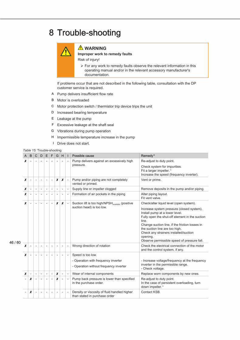
If problems occur that are not described in the following table, consultation with the DPcustomer service is required.Pump delivers insufficient flow rateMotor is overloadedMotor protection switch / thermistor trip device trips the unitIncreased bearing temperatureLeakage at the pumpExcessive leakage at the shaft sealVibrations during pump operationImpermissible temperature increase in the pumpDrive does not start.
Table 15: Trouble-shootingA B C D E F G H I Possible cause Remedy 6)
✘ - - - - - - - - Pump delivers against an excessively highpressure.
Re-adjust to duty point.Check system for impurities.Fit a larger impeller. 6)
Increase the speed (frequency inverter).✘ - - - - - ✘ ✘ - Pump and/or piping are not completely
vented or primed.Vent or prime.
✘ - - - - - - - - Supply line or impeller clogged Remove deposits in the pump and/or piping.✘ - - - - - - - - Formation of air pockets in the piping Alter piping layout.
Fit vent valve.✘ - - - - - ✘ ✘ - Suction lift is too high/NPSHavailable (positive
suction head) is too low.Check/alter liquid level (open system).Increase system pressure (closed system).Install pump at a lower level.Fully open the shut-off element in the suctionline.Change suction line, if the friction losses inthe suction line are too high.Check any strainers installed/suctionopening.Observe permissible speed of pressure fall.
✘ - - - - - - - - Wrong direction of rotation Check the electrical connection of the motorand the control system, if any.
✘ - - - - - - - - Speed is too low.- Operation with frequency inverter- Operation without frequency inverter
- Increase voltage/frequency at the frequencyinverter in the permissible range.- Check voltage.
✘ - - - - - ✘ - - Wear of internal components Replace worn components by new ones.- ✘ - - - - ✘ - - Pump back pressure is lower than specified
in the purchase order.Re-adjust to duty point.In the case of persistent overloading, turndown impeller. 6)
- ✘ - - - - - - - Density or viscosity of fluid handled higherthan stated in purchase order
Contact KSB.
8
A
B
C
D
E
F
G
H
I
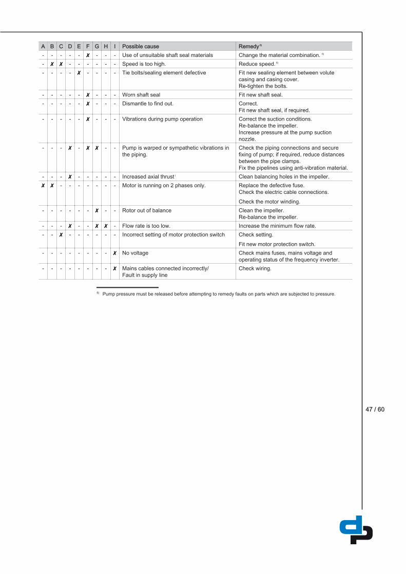
47 / 60
A B C D E F G H I Possible cause Remedy 6)
- - - - - ✘ - - - Use of unsuitable shaft seal materials Change the material combination. 6)
- ✘ ✘ - - - - - - Speed is too high. Reduce speed. 6)
- - - - ✘ - - - - Tie bolts/sealing element defective Fit new sealing element between volutecasing and casing cover.Re-tighten the bolts.
- - - - - ✘ - - - Worn shaft seal Fit new shaft seal.- - - - - ✘ - - - Dismantle to find out. Correct.
Fit new shaft seal, if required.- - - - - ✘ - - - Vibrations during pump operation Correct the suction conditions.
Re-balance the impeller.Increase pressure at the pump suctionnozzle.
- - - ✘ - ✘ ✘ - - Pump is warped or sympathetic vibrations inthe piping.
Check the piping connections and securefixing of pump; if required, reduce distancesbetween the pipe clamps.Fix the pipelines using anti-vibration material.
- - - ✘ - - - - - Increased axial thrust ) Clean balancing holes in the impeller.✘ ✘ - - - - - - - Motor is running on 2 phases only. Replace the defective fuse.
Check the electric cable connections.Check the motor winding.
- - - - - - ✘ - - Rotor out of balance Clean the impeller.Re-balance the impeller.
- - - ✘ - - ✘ ✘ - Flow rate is too low. Increase the minimum flow rate.- - ✘ - - - - - - Incorrect setting of motor protection switch Check setting.
Fit new motor protection switch.- - - - - - - - ✘ No voltage Check mains fuses, mains voltage and
operating status of the frequency inverter.- - - - - - - - ✘ Mains cables connected incorrectly/
Fault in supply lineCheck wiring.
6) Pump pressure must be released before attempting to remedy faults on parts which are subjected to pressure.

48 / 60
Related Documents
Typical installation positionsTable 16: Horizontal installationExample drawing Special features
Direction of flow frombottom to top
Direction of flow from bottom to top
Direction of flow fromtop to bottom
Direction of flow from top to bottomThe volute casing and/or back pull-out unit must be turned by 180° so that theterminal box remains in its current position on top.
1146:3/1
Horizontal installation
Horizontal installation (for example under the ceiling)The volute casing and/or back pull-out unit must be turned by 90° so that theterminal box remains in its current position on top.
1
Installation with blindflange
1 = Blind flange (accessories)If one of the pumps needs to be serviced, the pump chamber can be shut offby a blind flange so that the system remains operational.
Table 17: Vertical installationExample drawing Special features
Vertical installationwithout feet
Mounted without feetInstalled directly in the piping. Always anchor the pipes in close proximity tothe pump in this case.
9
9.1

49 / 60
Example drawing Special features
Vertical installationwith pump foot
Mounted on pump foot (accessory)Available upon request.

50 / 60
General drawing with list of components
102102
230
940.01
914.21
930
554.03
932
550.19
903.02
412.50 914.42 507.12
433 507.12 800
341
580161
903.39
550.18
UG1571731-D01-001/01
Fig. 7: General assembly drawing
Table 18: List of componentsPart No. Description Part No. Description102 Volute casing 554.03 Washer161 Casing cover 580 Cap230 Impeller 800 Motor341 Drive lantern 903.02/.39 Screw plug412.50 O-ring 914.21/.42 Hexagon socket head cap screw433 Mechanical seal 930 Safety device507.12 Thrower 932 Circlip550.18/.19 Disc 940.01 Key
Table 19: The following spare parts kits are available:Spare parts kits Part No. DescriptionCasing 102 Volute casing
412 O-ringImpeller 230 ImpellerShaft seal 433 Mechanical seal
932 CirclipMotor 970 Label/plate
563 Bolt/stud900 Screw950 Spring161 Casing cover801 Flanged motor433 Mechanical seal412 O-ring507 Thrower
9.2

51 / 60
Spare parts kits Part No. Description932 Circlip940 Key554 Washer914 Hexagon socket head cap screw930 Safety device

52 / 60
EU Declaration of Conformity
Manufacturer: Duijvelaar PompenDP Pumps
Kalkovenweg 132401 LJ Alphen aan den Rijn (The Netherlands)
The manufacturer herewith declares that the product:
Omega SL, Omega DSL (1~, 230 V)
Series code range : 2016w28 to 2017w52
– is in conformity with the provisions of the following Directives as amended from time to time:– Pump set: Machinery Directive 2006/42/EC
The manufacturer also declares that
– the following harmonised international standards have been applied:– ISO 12100– EN 809– EN 60034-1, EN 60034-5/A1– EN 60335-1/A1, EN 60335-2-41
Person authorised to compile the technical file:Wil OuwehandTechnical DirectorDuijvelaar PompenDP-PumpsKalkovenweg 132401 LJ Alphen aan den Rijn (The Netherlands)
The EU Declaration of Conformity was issued in/on:
Alphen aan den Rijn, 10 August 2016
Wil Ouwehand
Technical DirectorDuijvelaar Pompen
DP PumpsKalkovenweg 13
2401 LJ Alphen aan den Rijn (The Netherlands)
10

53 / 60
EU Declaration of Conformity
Manufacturer: Duijvelaar PompenDP Pumps
Kalkovenweg 132401 LJ Alphen aan den Rijn (The Netherlands)
The manufacturer herewith declares that the product:
Omega SL, Omega DSL (3~, Y Δ 400/230 V)
Series code range : 2016w28 to 2017w52
– is in conformity with the provisions of the following Directives as amended from time to time:– Pump set: Machinery Directive 2006/42/EC
The manufacturer also declares that
– the following harmonised international standards have been applied:– ISO 12100– EN 809– ISO 60034-1, ISO 60034-5/A1
Person authorised to compile the technical file:Wil OuwehandTechnical DirectorDuijvelaar PompenDP-PumpsKalkovenweg 132401 LJ Alphen aan den Rijn (The Netherlands)
The EU Declaration of Conformity was issued in/on:
Alphen aan den Rijn, 10 August 2016
Wil Ouwehand
Technical DirectorDuijvelaar Pompen
DP PumpsKalkovenweg 13
2401 LJ Alphen aan den Rijn (The Netherlands)
11
54 / 60
EU Declaration of Conformity
Manufacturer: Duijvelaar PompenDP Pumps
Kalkovenweg 132401 LJ Alphen aan den Rijn (The Netherlands)
The manufacturer herewith declares that the product:
Omega SL, Omega DSL
– is in conformity with the provisions of the following Directives as amended from time to time:– Pump (set): Ecodesign Directive 2009/125/EC, Regulation 547/2012
(for water pumps with a maximum shaft power of 150kW)
The EU Declaration of Conformity was issued in/on:
Alphen aan den Rijn, 11 July 2016
Wil Ouwehand
Technical DirectorDuijvelaar Pompen
DP PumpsKalkovenweg 13
2401 LJ Alphen aan den Rijn (The Netherlands)
12

55 / 60
Certificate of Decontamination
Type: ................................................................................................................................Order number/Order item number 7): ................................................................................................................................
Delivery date: ................................................................................................................................
Field of application: ................................................................................................................................
Fluid handled 7): ................................................................................................................................
Please tick where applicable 7):
⃞ ⃞ ⃞ ⃞Radioactive Explosive Corrosive Toxic
⃞ ⃞ ⃞ ⃞Harmful Bio-hazardous Highly flammable Safe
Reason for return 7): ................................................................................................................................
Comments: ................................................................................................................................
................................................................................................................................ The product/accessories have been carefully drained, cleaned and decontaminated inside and outside prior to dispatch/placingat your disposal.We herewith declare that this product is free from hazardous chemicals, biological and radioactive substances.For mag-drive pumps, the inner rotor unit (impeller, casing cover, bearing ring carrier, plain bearing, inner rotor) has beenremoved from the pump and cleaned. In cases of containment shroud leakage, the outer rotor, bearing bracket lantern, leakagebarrier and bearing bracket or intermediate piece have also been cleaned.For canned motor pumps, the rotor and plain bearing have been removed from the pump for cleaning. In cases of leakage atthe stator can, the stator space has been examined for fluid leakage; if fluid handled has penetrated the stator space, it hasbeen removed.
⃞ No special safety precautions are required for further handling.⃞ The following safety precautions are required for flushing fluids, fluid residues and disposal:
...............................................................................................................................................................
...............................................................................................................................................................We confirm that the above data and information are correct and complete and that dispatch is effected in accordance with therelevant legal provisions.
.................................................................... ....................................................... .......................................................Place, date and signature Address Company stamp
7) Required fields
13

56 / 60
IndexAAbrasive fluids 34Applications 10Automation 18Auxiliary connections 24
BBearing temperature 38Bearings 18
CCertificate of decontamination 55Commissioning 28
DDesign 17Designation 16Direction of rotation 30Dismantling 41Disposal 14Drive 18
EEvent of damage 7
Ordering spare parts 45Explosion protection 25, 32, 36
FFaults
Causes and remedies 46Filter 23, 39Fluid handled
Density 33Frequency of starts 33
IImpeller type 18Installation at site 21Intended use 10
MMaintenance 37Mechanical seal 31Misuse 10
NName plate 7, 17Noise characteristics 20
OOperating limits 32Other applicable documents 7
PPartly completed machinery 7Permissible forces at the pump nozzles 23Piping 22Preservation 14, 35Product description 16Pump casing 18
RReassembly 41, 43Return to supplier 14Returning to service 35
SSafety 9Safety awareness 11Scope of supply 20Shaft seal 18Shutdown 35Spare part
Ordering spare parts 45Spare parts stock 45Start-up 31Storage 14, 35
TTightening torques 27, 44Transport 13
WWarranty claims 7

57 / 60

58 / 60

59 / 60

duijvelaar pompenPostbus 282400 AA Alphen aan den Rijn (The Netherlands)
Tel.: +31 172 48 83 88Fax: +31 172 46 89 30
BelgiumTel.: +32 800 78 48 0www.duijvelaar-pompen.be
duijvelaar pompen
27/09/2016
BE00000629
(1513.8/01-EN)