Embed Size (px)
Citation preview
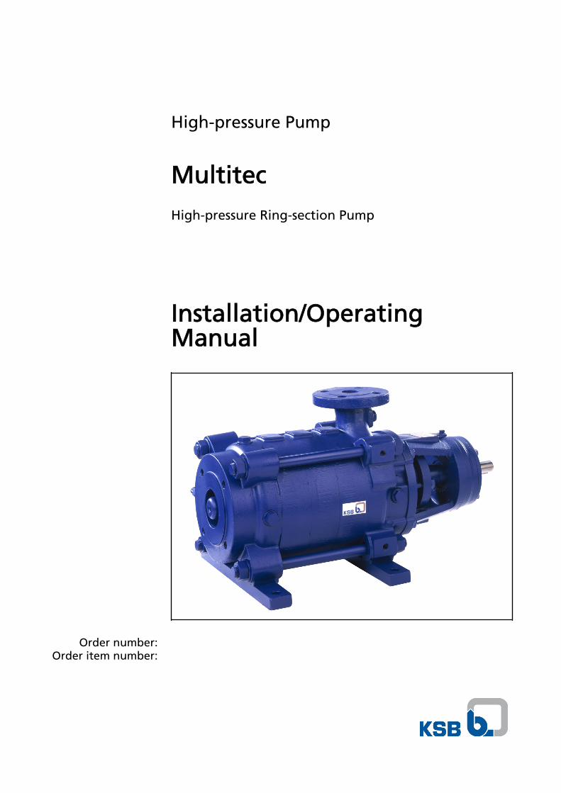
High-pressure Pump
Multitec
High-pressure Ring-section Pump
Installation/OperatingManual
Order number:Order item number:

Installation/Operating Manual MultitecOriginal operating manual KSB Aktiengesellschaft All rights reserved. Contents provided herein must neither be distributed, copied, reproduced,processed for any other purpose, nor otherwise transmitted to a third party without KSB´s expresswritten consent. Subject to technical modification without prior notice. © KSB Aktiengesellschaft Frankenthal 18.01.2010
Contents
Glossary ................................................................................................ 5
1 General ................................................................................................ 6
1.1 Principles .......................................................................................................... 6
1.2 Installation of partly completed machinery .................................................. 6
1.3 Target group ................................................................................................... 6
1.4 Other applicable documents .......................................................................... 6
1.5 Symbols ............................................................................................................ 6
2 Safety ................................................................................................... 8
2.1 Key to safety symbols/markings ..................................................................... 8
2.2 General ............................................................................................................ 8
2.3 Intended use .................................................................................................... 8
2.4 Personnel qualification and training ............................................................. 9
2.5 Consequences and risks caused by non-compliance with these operatinginstructions ...................................................................................................... 9
2.6 Safety awareness ............................................................................................. 9
2.7 Safety information for the operator/user .................................................... 10
2.8 Safety information for maintenance, inspection and installation work ... 10
2.9 Unauthorised modes of operation ............................................................... 10
2.10 Explosion protection ..................................................................................... 10
3 Transport/Temporary Storage/Disposal ........................................... 13
3.1 Transport ....................................................................................................... 13
3.2 Storage and preservation ............................................................................. 13
3.3 Return to supplier ......................................................................................... 14
3.4 Disposal .......................................................................................................... 14
4 Description of the Pump (Set) .......................................................... 15
4.1 General description ....................................................................................... 15
4.2 Designation ................................................................................................... 15
4.3 Name plate .................................................................................................... 16
4.4 Design details ................................................................................................ 16
4.5 Configuration and function ......................................................................... 17
4.6 Noise characteristics ...................................................................................... 18
4.7 Scope of supply ............................................................................................. 18
4.8 Dimensions and weights ............................................................................... 19
5 Installation at Site ............................................................................. 20
5.1 Safety regulations ......................................................................................... 20
5.2 Checking the site before installation ........................................................... 20
5.3 Setting up the pump set ............................................................................... 20
5.4 Piping ............................................................................................................. 22
Contents
Multitec 3 of 84
5.5 Checking the coupling alignment ................................................................ 25
5.6 Aligning the pump and motor ..................................................................... 26
5.7 Electrical connection ..................................................................................... 29
5.8 Checking the direction of rotation .............................................................. 30
6 Commissioning/Start-up/Shutdown ................................................. 32
6.1 Commissioning/start-up ................................................................................ 32
6.2 Operating limits ............................................................................................ 38
6.3 Shutdown/storage/preservation ................................................................... 40
6.4 Returning to service after storage ............................................................... 41
7 Servicing/Maintenance ...................................................................... 42
7.1 Safety regulations ......................................................................................... 42
7.2 Servicing/inspection ...................................................................................... 42
7.3 Drainage/disposal .......................................................................................... 48
7.4 Dismantling the pump set ............................................................................ 48
7.5 Reassembling the pump set .......................................................................... 61
7.6 Tightening torques ....................................................................................... 69
7.7 Spare parts stock ........................................................................................... 71
8 Trouble-shooting ............................................................................... 73
9 Related Documents ........................................................................... 75
9.1 General assembly drawing with list of components ................................... 75
10 EC Declaration of Conformity .......................................................... 80
11 Certificate of Decontamination ....................................................... 81
Index .................................................................................................. 82
Contents
4 of 84 Multitec
Glossary
Certificate of decontaminationA certificate of decontamination certifies thatthe pump (set) has been properly drained toeliminate any environmental and healthhazards arising from components in contactwith the fluid handled.
Discharge lineThe line which is connected to the dischargenozzle
DriveElectric / hydraulic drive, Diesel engine orturbine up to max. 4000 rpm.
Hydraulic systemThe part of the pump in which the kineticenergy is converted into pressure energy.
Pool of pumpsPumps which are purchased and storedindependently of their later use
PumpMachine without drive, additional componentsor accessories
Pump setComplete pump set consisting of pump, drive,additional components and accessories
RotorFully assembled unit of all rotating parts,without mechanical seal, rolling elementbearings or plain bearings
Suction lift line/suction head lineThe line which is connected to the suctionnozzle
Glossary
Multitec 5 of 84
1 General
1.1 Principles
This manual is supplied as an integral part of the type series and variants indicatedon the front cover. It describes the proper and safe use of this equipment in allphases of operation.
The name plate indicates the type series and size, the main operating data, the ordernumber and the order item number. The order number and order item number clearly identify the pump (set) and serve as identification for all further businessprocesses.
In the event of damage, immediately contact your nearest KSB service centre tomaintain the right to claim under warranty.
Noise characteristics (⇨ Section 4.6 Page 18)
1.2 Installation of partly completed machinery
To install partly completed machinery supplied by KSB, please refer to the sub-sections under Servicing/Maintenance.
1.3 Target group
This manual is aimed at the target group of trained and qualified specialist technicalpersonnel. (⇨ Section 2.4 Page 9)
1.4 Other applicable documents
Table 1: Overview of other applicable documents
Document ContentsData sheet Description of the technical data of the pump
(set)General arrangement drawing/Outline drawing
Description of mating and installation dimensionsfor the pump (set)
Drawing of auxiliary connections Description of auxiliary connectionsHydraulic characteristic curve Characteristic curves showing head, NPSH
required, efficiency and power inputGeneral assembly drawing1) Sectional drawing of the pump
Sub-supplier documentation1) Operating manuals and other documentation ofaccessories and integrated machinery components
Spare parts lists1) Description of spare parts
Piping layout1) Description of auxiliary piping
List of components1) Description of all pump components
1.5 Symbols
Table 2: Symbols used in this manual
Symbol Description✓ Conditions which need to be fulfilled before proceeding with the
step-by-step instructions⊳ Safety instructions⇨ Result of an action⇨ Cross-references
1) If agreed to be included in the scope of supply
1 General
6 of 84 Multitec
Symbol Description1.
2.
Step-by-step instructions
NoteRecommendations and important information on how to handlethe product
1 General
Multitec 7 of 84
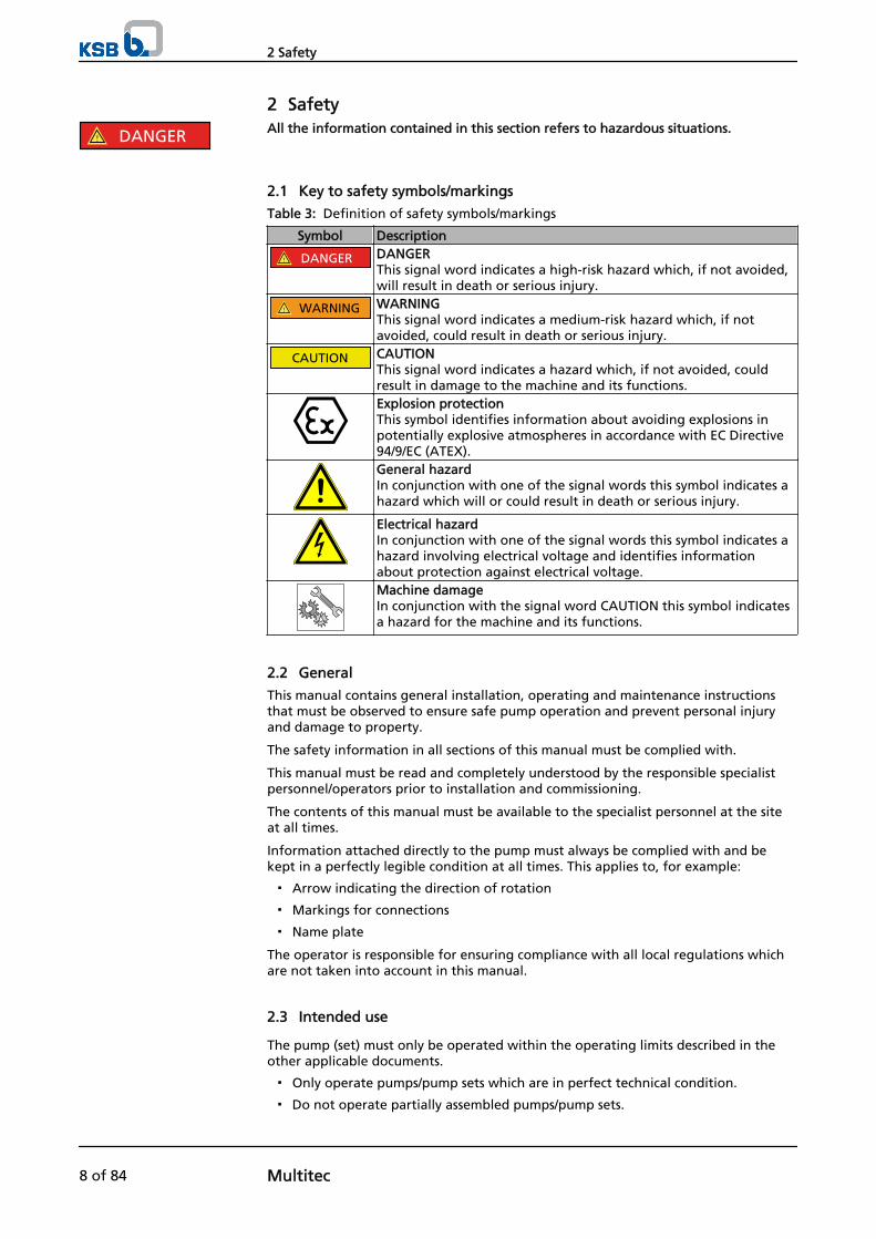
2 SafetyAll the information contained in this section refers to hazardous situations.
2.1 Key to safety symbols/markings
Table 3: Definition of safety symbols/markings
Symbol Description
! DANGER DANGERThis signal word indicates a high-risk hazard which, if not avoided,will result in death or serious injury.
! WARNING WARNINGThis signal word indicates a medium-risk hazard which, if notavoided, could result in death or serious injury.
CAUTION CAUTIONThis signal word indicates a hazard which, if not avoided, couldresult in damage to the machine and its functions.Explosion protectionThis symbol identifies information about avoiding explosions inpotentially explosive atmospheres in accordance with EC Directive94/9/EC (ATEX).General hazardIn conjunction with one of the signal words this symbol indicates ahazard which will or could result in death or serious injury.
Electrical hazardIn conjunction with one of the signal words this symbol indicates ahazard involving electrical voltage and identifies informationabout protection against electrical voltage.Machine damage In conjunction with the signal word CAUTION this symbol indicatesa hazard for the machine and its functions.
2.2 General
This manual contains general installation, operating and maintenance instructionsthat must be observed to ensure safe pump operation and prevent personal injuryand damage to property.
The safety information in all sections of this manual must be complied with.
This manual must be read and completely understood by the responsible specialistpersonnel/operators prior to installation and commissioning.
The contents of this manual must be available to the specialist personnel at the siteat all times.
Information attached directly to the pump must always be complied with and bekept in a perfectly legible condition at all times. This applies to, for example:
▪ Arrow indicating the direction of rotation
▪ Markings for connections
▪ Name plate
The operator is responsible for ensuring compliance with all local regulations whichare not taken into account in this manual.
2.3 Intended use
The pump (set) must only be operated within the operating limits described in theother applicable documents.
▪ Only operate pumps/pump sets which are in perfect technical condition.
▪ Do not operate partially assembled pumps/pump sets.
! DANGER
2 Safety
8 of 84 Multitec
▪ The pump must only be used to handle the fluids specified in the data sheet orproduct literature of the respective design variant.
▪ Never operate the pump without the fluid to be handled.
▪ Observe the minimum flow rates indicated in the data sheet or product literature(to prevent overheating, bearing damage, etc).
▪ Observe the maximum flow rates indicated in the data sheet or productliterature (to prevent overheating, mechanical seal damage, cavitation damage,bearing damage, etc).
▪ Do not throttle the flow rate on the suction side of the pump (to preventcavitation damage).
▪ Consult the manufacturer about any use or mode of operation not described inthe data sheet or product literature.
Prevention of foreseeable misuse
▪ Never open discharge-side shut-off elements further than permitted.
– The maximum flow rate specified in the data sheet or product literaturewould be exceeded.
– Risk of cavitation damage
▪ Never exceed the permissible operating limits specified in the data sheet orproduct literature regarding pressure, temperature, etc.
▪ Observe all safety information and instructions in this manual.
2.4 Personnel qualification and training
All personnel involved must be fully qualified to install, operate, maintain andinspect the machinery this manual refers to.
The responsibilities, competence and supervision of all personnel involved ininstallation, operation, maintenance and inspection must be clearly defined by theoperator.
Deficits in knowledge must be rectified by sufficiently trained specialist personneltraining and instructing the personnel who will carry out the respective tasks. Ifrequired, the operator can commission the manufacturer/supplier to train thepersonnel.
Training on the pump (set) must always be supervised by technical specialistpersonnel.
2.5 Consequences and risks caused by non-compliance with these operatinginstructions
▪ Non-compliance with these operating instructions will lead to forfeiture ofwarranty cover and of any and all rights to claims for damages.
▪ Non-compliance can, for example, have the following consequences:
– Hazards to persons due to electrical, thermal, mechanical and chemicaleffects and explosions
– Failure of important product functions
– Failure of prescribed maintenance and servicing practices
– Hazard to the environment due to leakage of hazardous substances
2.6 Safety awareness
In addition to the safety information contained in this manual and the intended use,the following safety regulations shall be complied with:
▪ Accident prevention, health and safety regulations
▪ Explosion protection regulations
2 Safety
Multitec 9 of 84
▪ Safety regulations for handling hazardous substances
▪ Applicable standards and laws
2.7 Safety information for the operator/user
▪ The operator shall fit contact guards for hot, cold or moving parts and check thatthe guards function properly.
▪ Do not remove the contact guard while the pump is running.
▪ Connect an earth conductor to the metal jacket if the fluid handled iselectrostatically charged.
▪ Provide the personnel with protective equipment and make sure it is used.
▪ Contain leakages (e.g at the shaft seal) of hazardous fluids handled (e.g.explosive, toxic, hot) so as to avoid any danger to persons and the environment.Adhere to all relevant laws.
▪ Eliminate all electrical hazards. (In this respect refer to the applicable nationalsafety regulations and/or regulations issued by the local energy supplycompanies.)
2.8 Safety information for maintenance, inspection and installation work
▪ Modifications or alterations of the pump are only permitted with themanufacturer's prior consent.
▪ Use only original spare parts or parts authorised by the manufacturer. The use ofother parts can invalidate any liability of the manufacturer for consequentialdamage.
▪ The operator ensures that all maintenance, inspection and installation work isperformed by authorised, qualified specialist personnel who are thoroughlyfamiliar with the manual.
▪ Carry out work on the pump (set) during standstill only.
▪ The pump casing must have cooled down to ambient temperature.
▪ Pump pressure must have been released and the pump must have been drained.
▪ When taking the pump set out of service always adhere to the proceduredescribed in the manual. (⇨ Section 6.1.7 Page 37)
▪ Decontaminate pumps which handle fluids posing a health hazard.
▪ As soon as the work is completed, re-install and/or re-activate any safety-relevantand protective devices. Before returning the product to service, observe allinstructions on commissioning. (⇨ Section 6.1 Page 32)
2.9 Unauthorised modes of operation
Never operate the pump (set) outside the limits stated in the data sheet and in thismanual.
The warranty relating to the operating reliability and safety of the supplied pump(set) is only valid if the equipment is used in accordance with its intended use. (⇨Section 2.3 Page 8)
2.10 Explosion protection
Always observe the instructions on explosion protection given in this section whenoperating the pump in potentially explosive atmospheres.
Only pumps/pump sets marked as explosion-proof and identified as such in the datasheet may be used in potentially explosive atmospheres.
Special conditions apply to the operation of explosion-proof pump sets to ECDirective 94/9/EC (ATEX). Especially adhere to the sections in this manual marked with the Ex symbol and thefollowing sections (⇨ Section 2.10.1 Page 11) to (⇨ Section 2.10.4 Page 12).
! DANGER
2 Safety
10 of 84 Multitec
The explosion-proof status of the pump set is only assured if the pump set is used inaccordance with its intended use. Never operate the pump (set) outside the limits stated in the data sheet and on thename plate.Prevent impermissible modes of operation at all times.
2.10.1 Marking
The marking on the pump refers to the pump only. Example of such marking: II 2 G c TX Refer to the Temperature limits table for the temperatures permitted for theindividual pump variants.
An EC manufacturer's declaration is required for the shaft coupling; the shaftcoupling must be marked accordingly.
The motor must be considered separately.
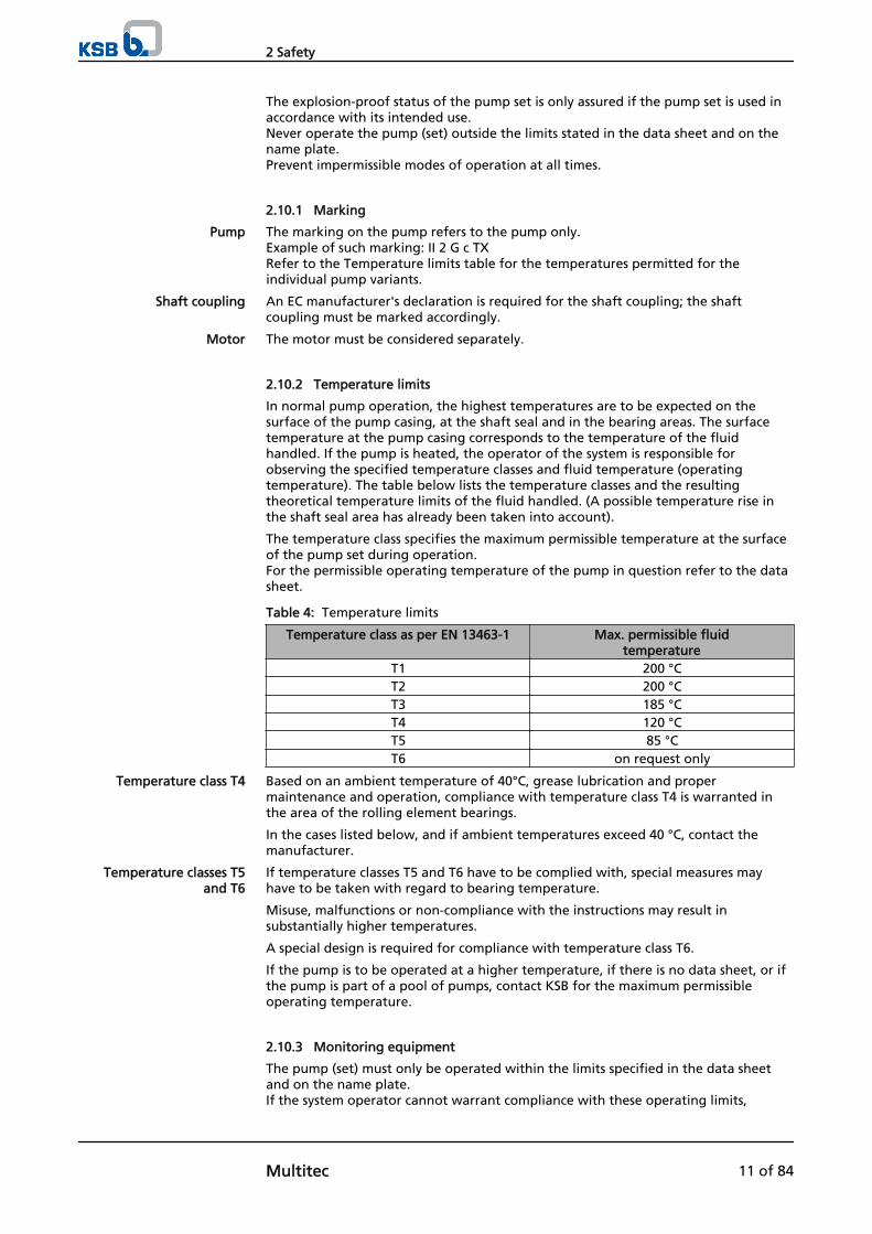
2.10.2 Temperature limits
In normal pump operation, the highest temperatures are to be expected on thesurface of the pump casing, at the shaft seal and in the bearing areas. The surfacetemperature at the pump casing corresponds to the temperature of the fluidhandled. If the pump is heated, the operator of the system is responsible forobserving the specified temperature classes and fluid temperature (operatingtemperature). The table below lists the temperature classes and the resultingtheoretical temperature limits of the fluid handled. (A possible temperature rise inthe shaft seal area has already been taken into account).
The temperature class specifies the maximum permissible temperature at the surfaceof the pump set during operation. For the permissible operating temperature of the pump in question refer to the datasheet.
Table 4: Temperature limits
Temperature class as per EN 13463-1 Max. permissible fluidtemperature
T1 200 °CT2 200 °CT3 185 °CT4 120 °CT5 85 °CT6 on request only
Based on an ambient temperature of 40°C, grease lubrication and propermaintenance and operation, compliance with temperature class T4 is warranted inthe area of the rolling element bearings.
In the cases listed below, and if ambient temperatures exceed 40 °C, contact themanufacturer.
If temperature classes T5 and T6 have to be complied with, special measures mayhave to be taken with regard to bearing temperature.
Misuse, malfunctions or non-compliance with the instructions may result insubstantially higher temperatures.
A special design is required for compliance with temperature class T6.
If the pump is to be operated at a higher temperature, if there is no data sheet, or ifthe pump is part of a pool of pumps, contact KSB for the maximum permissibleoperating temperature.
2.10.3 Monitoring equipment
The pump (set) must only be operated within the limits specified in the data sheetand on the name plate. If the system operator cannot warrant compliance with these operating limits,
Pump
Shaft coupling
Motor
Temperature class T4
Temperature classes T5and T6
2 Safety
Multitec 11 of 84
appropriate monitoring devices must be used. Check whether monitoring equipment is required to ensure that the pump setfunctions properly.
Contact KSB for further information on monitoring equipment.
2.10.4 Operating limits
The minimum flows indicated in (⇨ Section 6.2.3 Page 39) refer to water and water-like fluids. Longer operating periods with these fluids and at the flow rates indicatedwill not cause an additional increase in the temperatures on the pump surface.However, if the physical properties of the fluids handled are different from water, itis essential to check if an additional heat build-up may occur and if the minimumflow rate must therefore be increased. The calculation formula in (⇨ Section 6.2.3Page 39) can be used to check if an additional heat build-up may lead to ahazardous temperature increase at the pump surface.
2 Safety
12 of 84 Multitec
3 Transport/Temporary Storage/Disposal
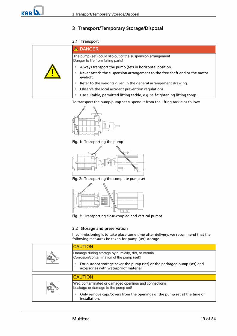
3.1 Transport
DANGERThe pump (set) could slip out of the suspension arrangementDanger to life from falling parts!
▷ Always transport the pump (set) in horizontal position.
▷ Never attach the suspension arrangement to the free shaft end or the motoreyebolt.
▷ Refer to the weights given in the general arrangement drawing.
▷ Observe the local accident prevention regulations.
▷ Use suitable, permitted lifting tackle, e.g. self-tightening lifting tongs.
To transport the pump/pump set suspend it from the lifting tackle as follows.
Fig. 1: Transporting the pump
Fig. 2: Transporting the complete pump set
Fig. 3: Transporting close-coupled and vertical pumps
3.2 Storage and preservation
If commissioning is to take place some time after delivery, we recommend that thefollowing measures be taken for pump (set) storage.
CAUTIONDamage during storage by humidity, dirt, or verminCorrosion/contamination of the pump (set)!
▷ For outdoor storage cover the pump (set) or the packaged pump (set) andaccessories with waterproof material.
CAUTIONWet, contaminated or damaged openings and connectionsLeakage or damage to the pump set!
▷ Only remove caps/covers from the openings of the pump set at the time ofinstallation.
3 Transport/Temporary Storage/Disposal
Multitec 13 of 84
Store the pump (set) in a dry, protected room where the atmospheric humidity is asconstant as possible.
Rotate the shaft by hand once a month, e.g. via the motor fan.
If properly stored indoors, the pump set is protected for three months (please referto order or order confirmation).New pumps/pump sets are supplied by our factory duly prepared for storage.
For storage periods exceeding three months, the pump set is preserved as specified inthe purchase order (please refer to order or order confirmation).
3.3 Return to supplier
1. Drain the pump as per operating instructions. (⇨ Section 7.3 Page 48)
2. Always flush and clean the pump, particularly if it has been used for handlingnoxious, explosive, hot or other hazardous fluids.
3. If the fluids handled by the pump leave residues which might lead to corrosiondamage when coming into contact with atmospheric humidity, or which mightignite when coming into contact with oxygen, the pump set must also beneutralised, and anhydrous gas must be blown through the pump for dryingpurposes.
4. Always complete and enclose a certificate of decontamination when returningthe pump set. (⇨ Section 11 Page 81)It is imperative to indicate any safety and decontamination measures taken.
NOTEIf required, a blank certificate of decontamination can be downloaded from the KSB website at: www.ksb.com/certificate_of_decontamination
3.4 Disposal
WARNINGFluids posing a health hazardHazardous to persons and the environment!
▷ Collect and properly dispose of flushing liquid and any fluid residues.
▷ Wear safety clothing and a protective mask, if required.
▷ Observe all legal regulations on the disposal of fluids posing a health hazard.
1. Dismantle the pump (set).Collect greases and other lubricants during dismantling.
2. Separate and sort the pump materials, e.g. by:- Metals- Plastics- Electronic waste- Greases and other lubricants
3. Dispose of materials in acc. with local regulations or in another controlledmanner.
3 Transport/Temporary Storage/Disposal
14 of 84 Multitec
4 Description of the Pump (Set)
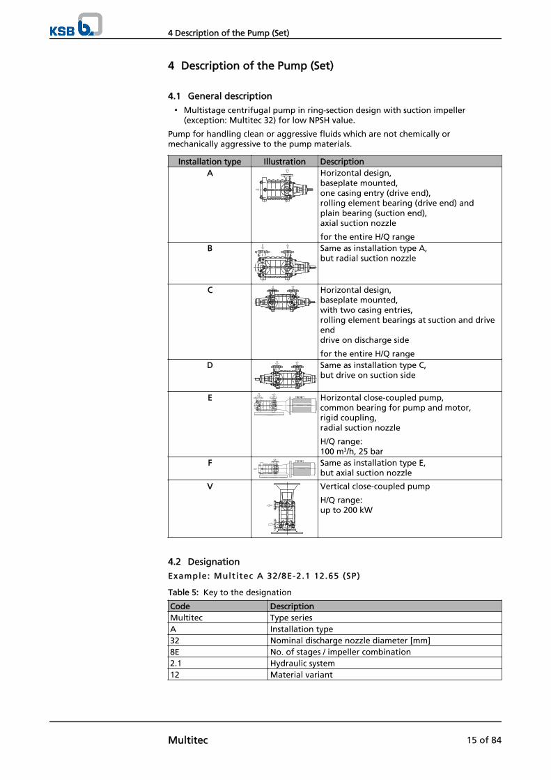
4.1 General description
▪ Multistage centrifugal pump in ring-section design with suction impeller(exception: Multitec 32) for low NPSH value.
Pump for handling clean or aggressive fluids which are not chemically ormechanically aggressive to the pump materials.
Installation type Illustration DescriptionA Horizontal design,
baseplate mounted,one casing entry (drive end), rolling element bearing (drive end) andplain bearing (suction end), axial suction nozzle
for the entire H/Q rangeB Same as installation type A,
but radial suction nozzle
C Horizontal design, baseplate mounted,with two casing entries, rolling element bearings at suction and driveenddrive on discharge side
for the entire H/Q rangeD Same as installation type C,
but drive on suction side
E Horizontal close-coupled pump,common bearing for pump and motor,rigid coupling,radial suction nozzle
H/Q range: 100 m3/h, 25 bar
F Same as installation type E, but axial suction nozzle
V Vertical close-coupled pump
H/Q range: up to 200 kW
4.2 Designation
Example: Mult i tec A 32/8E-2.1 12.65 (SP)
Table 5: Key to the designation
Code DescriptionMultitec Type seriesA Installation type32 Nominal discharge nozzle diameter [mm]8E No. of stages / impeller combination2.1 Hydraulic system12 Material variant
4 Description of the Pump (Set)
Multitec 15 of 84
Code Description65 Seal codeSP Code for special variants (optional)
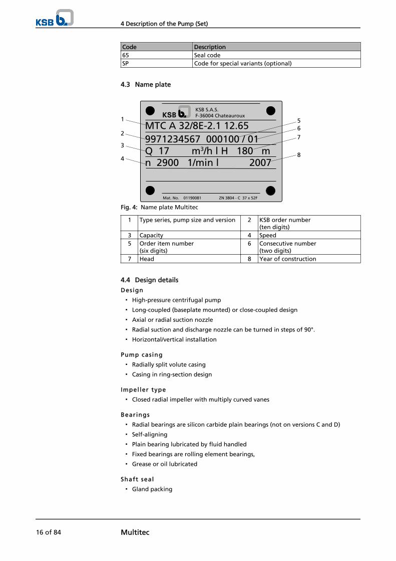
4.3 Name plate
MTC A 32/8E-2.1 12.659971234567 000100 / 01Q 17 m3/h l H 180 mn 2900 1/min l 2007
KSB S.A.S.F-36004 Chateauroux
Mat. No. 01190081 ZN 3804 - C 37 x 52F
1
2
4
3
8
7
65
Fig. 4: Name plate Multitec
1 Type series, pump size and version 2 KSB order number(ten digits)
3 Capacity 4 Speed5 Order item number
(six digits)6 Consecutive number
(two digits)7 Head 8 Year of construction
4.4 Design details
Design
▪ High-pressure centrifugal pump
▪ Long-coupled (baseplate mounted) or close-coupled design
▪ Axial or radial suction nozzle
▪ Radial suction and discharge nozzle can be turned in steps of 90°.
▪ Horizontal/vertical installation
Pump cas ing
▪ Radially split volute casing
▪ Casing in ring-section design
Impel ler type
▪ Closed radial impeller with multiply curved vanes
Bearings
▪ Radial bearings are silicon carbide plain bearings (not on versions C and D)
▪ Self-aligning
▪ Plain bearing lubricated by fluid handled
▪ Fixed bearings are rolling element bearings,
▪ Grease or oil lubricated
Shaft seal
▪ Gland packing
4 Description of the Pump (Set)
16 of 84 Multitec

DANGERExcessive temperatures in the shaft seal areaRisk of explosion!
▷ Never operate a pump (set) with gland packing in potentially explosiveatmospheres.
▪ Standardised mechanical seal to EN 12756
▪ Double-acting mechanical seal with standardised mechanical seals to EN 12756(back-to-back or tandem).
▪ Cartridge-type
▪ Special designs
4.5 Configuration and function
1 432 5
6 87 1413121110 159
Fig. 5: Sectional drawing
1 Clearance gap 2 Discharge nozzle3 Discharge casing 4 Shaft5 Bearing housing 6 Suction casing7 Plain bearing 8 (Suction) impeller9 Diffuser 10 Stage casing11 Impeller 12 Balance drum13 Shaft seal housing 14 Shaft seal15 Rolling element bearing
The pump is designed with an axial or radial fluid inlet and a radial outlet. Thehydraulic system runs in its own bearings and is connected to the motor via a shaftcoupling.
The fluid enters the pump via the suction casing (6) and is accelerated by the rotating(suction) impeller (8), resulting in a cylindrical flow towards the outside of the pump.At the flow contour of the stage casing (10) the kinetic energy of the fluid isconverted into pressure energy and the fluid is routed to the next impeller (11) viathe diffuser (9). This process is repeated in all stages until the fluid has passed the lastimpeller. It then passes through the discharge casing (3) to the discharge nozzle (2),from where it leaves the pump. The clearance gap (1) prevents any fluid fromflowing back from the stage casing (10) into the suction range of the previousimpeller. If required, a balance drum (12) is fitted behind the last impeller, providingaxial thrust balancing by means of hydraulic forces. Behind the last impeller (11) andthe balancing drum (12), the hydraulic system is closed off by a seal housing (13)
Design
Function
4 Description of the Pump (Set)
Multitec 17 of 84
through which the drive shaft (4) passes. The shaft passage through the seal housing(13) is sealed towards the atmosphere by a dynamic shaft seal (14). The drive shaft (4)is supported by rolling element bearings (15) and plain bearings (7) located in abearing housing (5) and the suction casing (6), respectively. The bearing housing (5) isconnected with the suction and/or discharge casing (6 and 3).
The pump is sealed by a shaft seal.Standardised mechanical seal or packed gland
4.6 Noise characteristics
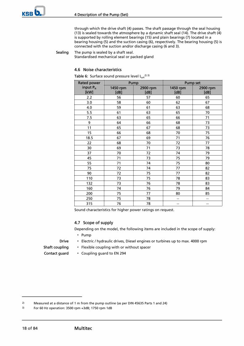
Table 6: Surface sound pressure level LpA2) 3)
Rated powerinput PN
[kW]
Pump Pump set1450 rpm
[dB]2900 rpm
[dB]1450 rpm
[dB]2900 rpm
[dB]2.2 56 57 60 653.0 58 60 62 674.0 59 61 63 685.5 61 63 65 707.5 63 65 66 719 64 66 68 73
11 65 67 68 7315 66 68 70 75
18.5 67 69 71 7622 68 70 72 7730 69 71 73 7837 70 72 74 7945 71 73 75 7955 71 74 75 8075 72 74 77 8290 72 75 77 82
110 73 75 78 83132 73 76 78 83160 74 76 79 84200 75 77 80 85250 75 78 -- --315 76 78 -- --
Sound characteristics for higher power ratings on request.
4.7 Scope of supply
Depending on the model, the following items are included in the scope of supply:
▪ Pump
▪ Electric / hydraulic drives, Diesel engines or turbines up to max. 4000 rpm
▪ Flexible coupling with or without spacer
▪ Coupling guard to EN 294
Sealing
Drive
Shaft coupling
Contact guard
2) Measured at a distance of 1 m from the pump outline (as per DIN 45635 Parts 1 and 24)3) For 60 Hz operation: 3500 rpm +3dB; 1750 rpm 1dB
4 Description of the Pump (Set)
18 of 84 Multitec
DANGERRisk of ignition by frictional sparksRisk of explosion!
▷ Choose a coupling guard material that is non-sparking in the event ofmechanical contact (see DIN EN 13463-1).
▷ If any coupling parts are made of aluminium, a brass coupling guard must beused.
▪ Channel section steel, welded
▪ U-rail
▪ As required
4.8 Dimensions and weights
For dimensions and weights please refer to the general arrangement drawing/outlinedrawing of the pump (set).
Baseplate
Special accessories
4 Description of the Pump (Set)
Multitec 19 of 84
5 Installation at Site
5.1 Safety regulations
DANGERImproper installation in potentially explosive atmospheresExplosion hazard!Damage to the pump set!
▷ Comply with the applicable local explosion protection regulations.
▷ Observe the information in the data sheet and on the name plates of pump andmotor.
WARNINGPump with long-term preservation: Harmful preservatives in drinking water systemsDanger of poisoning!
▷ Flush the system prior to commissioning.
▷ If necessary, dismantle the pump and thoroughly remove the preservative fromall wetted components.
▷ Observe the data given in the order confirmation.
5.2 Checking the site before installation
Place of instal lat ion
WARNINGInstallation on foundations which are unsecured and cannot support the loadPersonal injury and damage to property!
▷ Make sure the foundation concrete is of sufficient strength (min. X0 toDIN 1045).
▷ Only place the pump set on a foundation whose concrete has set firmly.
▷ Only place the pump set on a horizontal and level surface.
▷ Refer to the weights given in the general arrangement drawing.
1. Check the structural requirements. All structural work required must have been prepared in accordance with thedimensions stated in the outline drawing/general arrangement drawing.
5.3 Setting up the pump set
CAUTIONWarped baseplate or pumpDamage to the pump!
▷ Align the baseplate and the pump accurately and carefully when setting up thepump set.
5 Installation at Site
20 of 84 Multitec
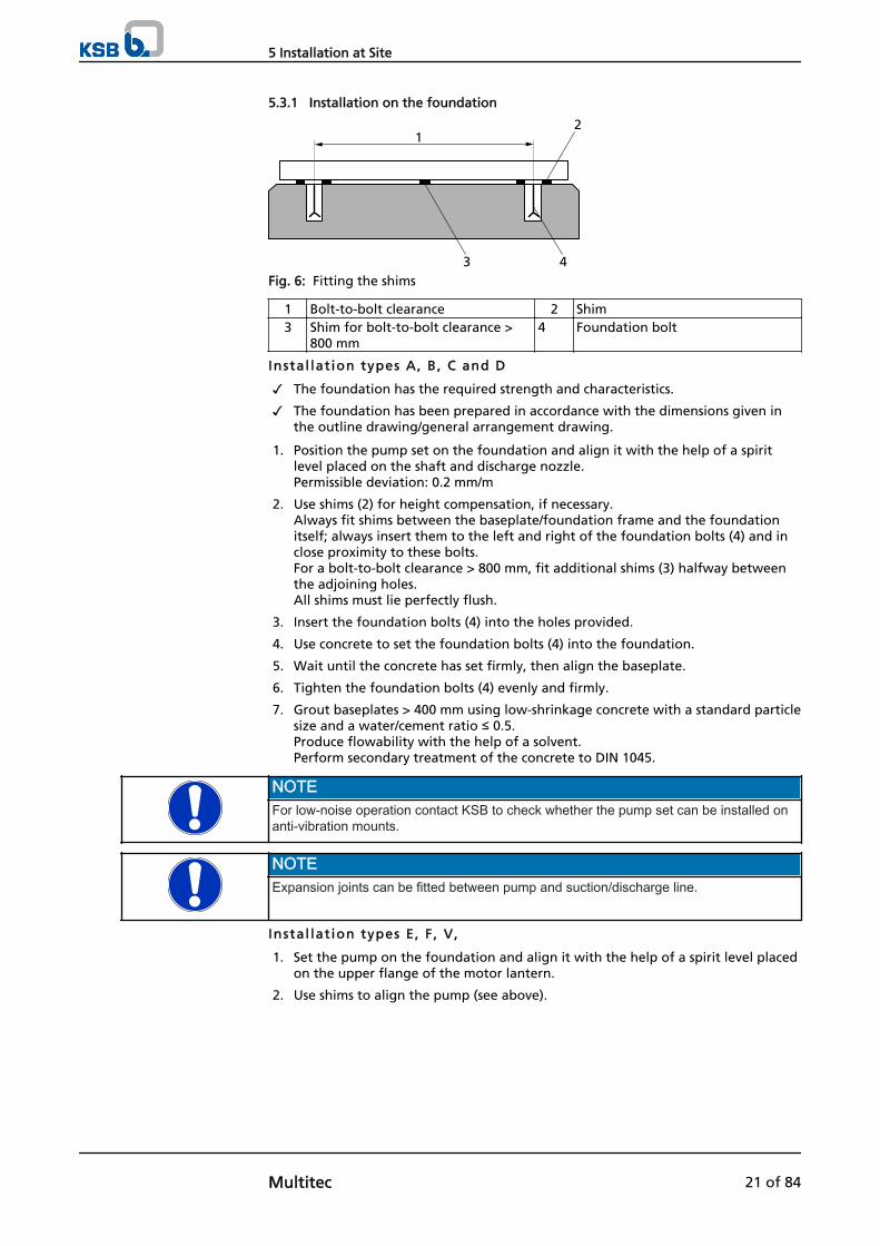
5.3.1 Installation on the foundation
12
43Fig. 6: Fitting the shims
1 Bolt-to-bolt clearance 2 Shim3 Shim for bolt-to-bolt clearance >
800 mm4 Foundation bolt
Instal lat ion types A, B, C and D
✓ The foundation has the required strength and characteristics.
✓ The foundation has been prepared in accordance with the dimensions given inthe outline drawing/general arrangement drawing.
1. Position the pump set on the foundation and align it with the help of a spiritlevel placed on the shaft and discharge nozzle.Permissible deviation: 0.2 mm/m
2. Use shims (2) for height compensation, if necessary. Always fit shims between the baseplate/foundation frame and the foundationitself; always insert them to the left and right of the foundation bolts (4) and inclose proximity to these bolts.For a bolt-to-bolt clearance > 800 mm, fit additional shims (3) halfway betweenthe adjoining holes. All shims must lie perfectly flush.
3. Insert the foundation bolts (4) into the holes provided.
4. Use concrete to set the foundation bolts (4) into the foundation.
5. Wait until the concrete has set firmly, then align the baseplate.
6. Tighten the foundation bolts (4) evenly and firmly.
7. Grout baseplates > 400 mm using low-shrinkage concrete with a standard particlesize and a water/cement ratio ≤ 0.5. Produce flowability with the help of a solvent. Perform secondary treatment of the concrete to DIN 1045.
NOTEFor low-noise operation contact KSB to check whether the pump set can be installed onanti-vibration mounts.
NOTEExpansion joints can be fitted between pump and suction/discharge line.
Instal lat ion types E, F , V,
1. Set the pump on the foundation and align it with the help of a spirit level placedon the upper flange of the motor lantern.
2. Use shims to align the pump (see above).
5 Installation at Site
Multitec 21 of 84

5.4 Piping
5.4.1 Connecting the piping
DANGERExcessive loads acting on the pump nozzlesDanger to life from leakage of hot, toxic, corrosive or flammable fluids!
▷ Do not use the pump as an anchorage point for the piping.
▷ Anchor the pipelines in close proximity to the pump and connect them withouttransmitting any stresses or strains.
▷ Observe the permissible forces and moments at the pump nozzles.
▷ Take appropriate measures to compensate thermal expansion of the piping.
CAUTIONIncorrect earthing during welding work at the pipingDestruction of rolling element bearings (pitting effect)!
▷ Never earth the electric welding equipment on the pump or baseplate.
▷ Prevent current flowing through the rolling element bearings.
NOTEIt is recommended to install check and shut-off elements in the system, depending on thetype of plant and pump. However, such elements must not obstruct proper drainage orhinder disassembly of the pump.
✓ The suction lift line/suction head line has been laid with a rising/downward slopetowards the pump.
✓ The nominal diameters of the pipelines are at least equal to the nominaldiameters of the pump nozzles.
✓ To prevent excessive pressure losses, adapters to larger diameters have a diffuserangle of approx. 8°.
✓ The pipelines have been anchored in close proximity to the pump and connectedwithout transmitting any stresses or strains.
1. Thoroughly clean, flush and blow through all vessels, pipelines and connections(especially of new installations).
2. Before installing the pump in the piping, remove the flange covers on the suctionand discharge nozzles of the pump.Multitec A: Do not close the hole provided in the plain bearing cover.
CAUTIONWelding beads, scale and other impurities in the pipingDamage to the pump!
▷ Free the piping from any impurities.
▷ If necessary, install a filter.
▷ Observe the instructions in (⇨ Section 7.2.2.3 Page 45).
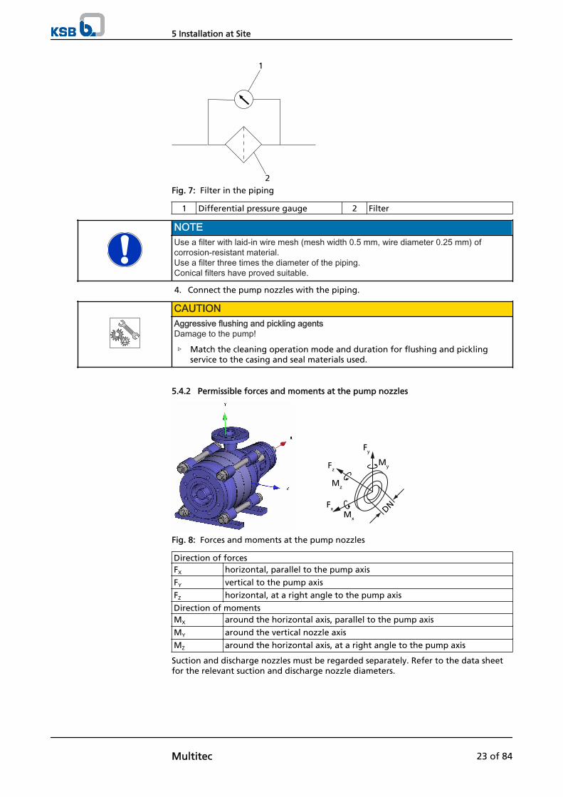
3. If required, install a filter in the piping (see illustration: Filter in the piping).
5 Installation at Site
22 of 84 Multitec
1
2Fig. 7: Filter in the piping
1 Differential pressure gauge 2 Filter
NOTEUse a filter with laid-in wire mesh (mesh width 0.5 mm, wire diameter 0.25 mm) ofcorrosion-resistant material.Use a filter three times the diameter of the piping.Conical filters have proved suitable.
4. Connect the pump nozzles with the piping.
CAUTIONAggressive flushing and pickling agentsDamage to the pump!
▷ Match the cleaning operation mode and duration for flushing and picklingservice to the casing and seal materials used.
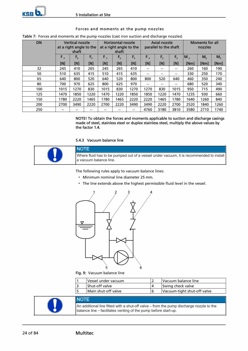
5.4.2 Permissible forces and moments at the pump nozzles
Fx
Fz
Fy
My
Mz
MxDN
Fig. 8: Forces and moments at the pump nozzles
Direction of forcesFX horizontal, parallel to the pump axis
FY vertical to the pump axis
FZ horizontal, at a right angle to the pump axis
Direction of momentsMX around the horizontal axis, parallel to the pump axis
MY around the vertical nozzle axis
MZ around the horizontal axis, at a right angle to the pump axis
Suction and discharge nozzles must be regarded separately. Refer to the data sheetfor the relevant suction and discharge nozzle diameters.
5 Installation at Site
Multitec 23 of 84
Forces and moments at the pump nozzles
Table 7: Forces and moments at the pump nozzles (cast iron suction and discharge nozzles)
DN Vertical nozzleat a right angle to the
shaft
Horizontal nozzleat a right angle to the
shaft
Axial nozzleparallel to the shaft
Moments for allnozzles
F x
[N]
Fy
[N]
Fz
[N]
F x
[N]
Fy
[N]
Fz
[N]
F x
[N]
Fy
[N]
Fz
[N]
M x
[Nm]
My
[Nm]
Mz
[Nm]32 245 410 265 245 265 410 -- -- -- 260 160 19050 510 635 415 510 415 635 -- -- -- 330 250 17065 640 800 520 640 520 800 800 520 640 460 350 24080 700 970 625 800 625 970 -- -- -- 680 520 340100 1015 1270 830 1015 830 1270 1270 830 1015 950 715 490125 1470 1850 1220 1470 1220 1850 1850 1220 1470 1235 930 660150 1780 2220 1465 1780 1465 2220 2220 1465 1780 1640 1260 840200 2700 3490 2220 2700 2220 3490 3490 2220 2700 2520 1840 1260250 -- -- -- -- -- -- 4760 3180 3810 3580 2710 1740
NOTE! To obtain the forces and moments applicable to suction and discharge casingsmade of steel, stainless steel or duplex stainless steel, multiply the above values bythe factor 1.4.
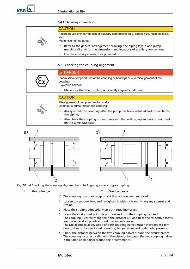
5.4.3 Vacuum balance line
NOTEWhere fluid has to be pumped out of a vessel under vacuum, it is recommended to installa vacuum balance line.
The following rules apply to vacuum balance lines:
▪ Minimum nominal line diameter 25 mm.
▪ The line extends above the highest permissible fluid level in the vessel.
1 2
5
43
6Fig. 9: Vacuum balance line
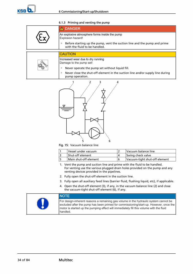
1 Vessel under vacuum 2 Vacuum balance line3 Shut-off valve 4 Swing check valve5 Main shut-off valve 6 Vacuum-tight shut-off valve
NOTEAn additional line fitted with a shut-off valve – from the pump discharge nozzle to thebalance line – facilitates venting of the pump before start-up.
5 Installation at Site
24 of 84 Multitec
5.4.4 Auxiliary connections
CAUTIONFailure to use or incorrect use of auxiliary connections (e.g. barrier fluid, flushing liquid,etc.)Malfunction of the pump!
▷ Refer to the general arrangement drawing, the piping layout and pumpmarkings (if any) for the dimensions and locations of auxiliary connections.
▷ Use the auxiliary connections provided.
5.5 Checking the coupling alignment
DANGERInadmissible temperatures at the coupling or bearings due to misalignment of thecouplingExplosion hazard!
▷ Make sure that the coupling is correctly aligned at all times.
CAUTIONMisalignment of pump and motor shaftsDamage to pump, motor and coupling!
▷ Always check the coupling after the pump has been installed and connected tothe piping.
▷ Also check the coupling of pump sets supplied with pump and motor mountedon the same baseplate.
BA
A B
a) b)
B
B
A
A
1
1 2 21
1
Fig. 10: a) Checking the coupling alignment and b) Aligning a spacer-type coupling
1 Straight-edge 2 Wedge gauge
✓ The coupling guard and step guard, if any, have been removed.
1. Loosen the support foot and re-tighten it without transmitting any stresses andstrains.
2. Place the straight-edge axially on both coupling halves.
3. Leave the straight-edge in this position and turn the coupling by hand. The coupling is correctly aligned if the distances A) and B) to the respective shaftsare the same at all points around the circumference.The radial and axial deviation of both coupling halves must not exceed 0.1 mmduring standstill as well as at operating temperature and under inlet pressure.
4. Check the distance between the two coupling halves around the circumference. The coupling is correctly aligned if the distance between the two coupling halvesis the same at all points around the circumference.
5 Installation at Site
Multitec 25 of 84
The radial and axial deviation of both coupling halves must not exceed 0.1 mmduring standstill as well as at operating temperature and under inlet pressure.
5.6 Aligning the pump and motor
5.6.1 Thermal expansion
CAUTIONIncrease in length and height at fluid temperatures > 100 °CWarping and deformation of the pump (set)!
▷ Tighten the foot bolts holding the pump on the baseplate to the torque givenin the table below (to prevent length increase).
▷ Note different height increases of pump and drive.The equation given below serves as a guide to estimate the increase in height.
▷ Verify the correct alignment of pump and motor at operating temperature andre-align, if necessary.
To prevent thermal length expansion, the following torques must be complied with:
Table 8: Bolt tightening torques for fastening the pump on the baseplate
Pump size Thread Property class Tightening torqueDrive end
[Nm]Non-drive end
[Nm]32 M12 4.6 30 1550 M12 4.6 30 1565 M16 4.6 60 30
100 M20 4.6 120 60125 M20 4.6 120 60150 M30 4.6 450 200
When aligning the coupling, bear in mind that the increase in height of pump anddrive due to thermal expansion may differ.
The following equation can serve as a guide to estimate by how much the motor hasto be elevated in relation to the pump:
ΔH[mm] = 1/100000 * (ΔTp * Hp - ΔTm * Hm)
ΔTp = Temperature difference pump - ambient [°C]Hp = Height of pump axis [mm]ΔTm = Temperature difference motor - ambient [°C]Hm = Height of motor axis [mm]
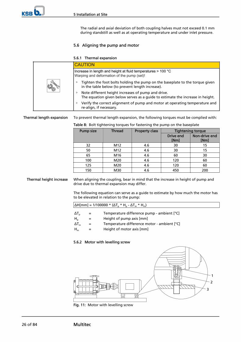
5.6.2 Motor with levelling screw
1
3
2
Fig. 11: Motor with levelling screw
Thermal length expansion
Thermal height increase
5 Installation at Site
26 of 84 Multitec
1 Hexagon head bolt 2 Levelling screw3 Lock nut
✓ The coupling guard and step guard, if any, have been removed.
1. Check the coupling alignment.
2. Unscrew the hexagon head bolts (1) at the motor and the lock nuts (3) at thebaseplate.
3. Turn the levelling screws (2) by hand or by means of an open-jawed wrench untilthe coupling alignment is correct.
4. Re-tighten the hexagon head bolts (1) at the motor and the lock nuts (3) at thebaseplate.
5. Check that the coupling and shaft can easily be rotated by hand.
WARNINGUnprotected rotating couplingRisk of injury by rotating shafts!
▷ Always operate the pump set with a coupling guard.If the customer specifically requests not to include a coupling guard in KSB'sdelivery, then the operator must supply one!
▷ Observe all relevant regulations for selecting a coupling guard.
DANGERRisk of ignition by frictional sparksExplosion hazard!
▷ Choose a coupling guard material that is non-sparking in the event ofmechanical contact (see DIN EN 13463-1).
6. Re-install the coupling guard and step guard, if any.
7. Check the distance between coupling and coupling guard.The coupling guard must not touch the coupling.
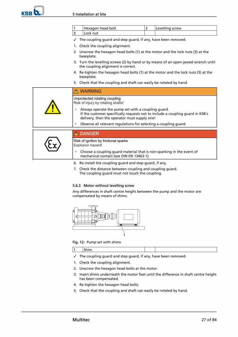
5.6.3 Motor without levelling screw
Any differences in shaft centre height between the pump and the motor arecompensated by means of shims.
1
Fig. 12: Pump set with shims
1 Shim
✓ The coupling guard and step guard, if any, have been removed.
1. Check the coupling alignment.
2. Unscrew the hexagon head bolts at the motor.
3. Insert shims underneath the motor feet until the difference in shaft centre heighthas been compensated.
4. Re-tighten the hexagon head bolts.
5. Check that the coupling and shaft can easily be rotated by hand.
5 Installation at Site
Multitec 27 of 84
WARNINGUnprotected rotating couplingRisk of injury by rotating shafts!
▷ Always operate the pump set with a coupling guard.If the customer specifically requests not to include a coupling guard in KSB'sdelivery, then the operator must supply one!
▷ Observe all relevant regulations for selecting a coupling guard.
DANGERRisk of ignition by frictional sparksExplosion hazard!
▷ Choose a coupling guard material that is non-sparking in the event ofmechanical contact (see DIN EN 13463-1).
6. Re-install the coupling guard and step guard, if any.
7. Check the distance between coupling and coupling guard.The coupling guard must not touch the coupling.
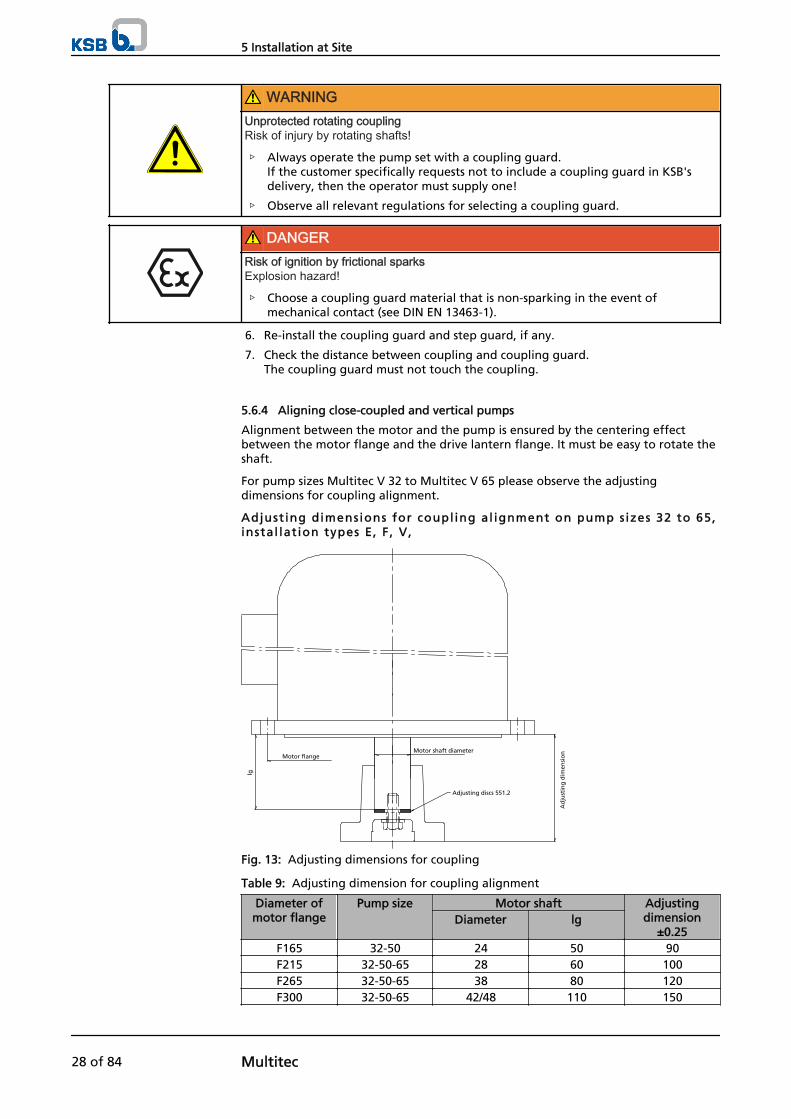
5.6.4 Aligning close-coupled and vertical pumps
Alignment between the motor and the pump is ensured by the centering effectbetween the motor flange and the drive lantern flange. It must be easy to rotate theshaft.
For pump sizes Multitec V 32 to Multitec V 65 please observe the adjustingdimensions for coupling alignment.
Adjust ing dimensions for coupl ing al ignment on pump s izes 32 to 65,instal lat ion types E, F , V,
Adjusting discs 551.2
Motor flangeMotor shaft diameter
Ad
just
ing
dim
ensi
on
lg
Fig. 13: Adjusting dimensions for coupling
Table 9: Adjusting dimension for coupling alignment
Diameter ofmotor flange
Pump size Motor shaft Adjustingdimension
±0.25Diameter lg
F165 32-50 24 50 90F215 32-50-65 28 60 100F265 32-50-65 38 80 120F300 32-50-65 42/48 110 150
5 Installation at Site
28 of 84 Multitec
Diameter ofmotor flange
Pump size Motor shaft Adjustingdimension
±0.25Diameter lg
F350 65 48/55 110 150F350 32-50 48/55 110 153F400 32-50-65 55 110 153
F400/F500 32-50-65 60 140 183F500/600 65 65 140 183
F600 65 80 170 213
5.7 Electrical connection
DANGERIncorrect electrical installationExplosion hazard!
▷ For electrical installation, also observe the requirements of IEC 60079-14.
▷ Always connect explosion-proof motors via a motor protection switch.
DANGERWork on the pump set by unqualified personnelDanger of death from electric shock!
▷ Always have the electrical connections installed by a trained electrician.
▷ Observe regulations IEC 30364 (DIN VDE 0100) and, for explosion-proof pumpsets, IEC 60079 (DIN VDE 0165).
WARNINGIncorrect connection to the mainsDamage to the mains network, short circuit!
▷ Observe the technical specifications of the local energy supply companies.
1. Check the available mains voltage against the data on the motor name plate.
2. Select an appropriate start-up method.
NOTEIt is recommended to fit a motor protection device.
5.7.1 Setting the time relay
CAUTIONSwitchover between star and delta on three-phase motors with star-delta starting takestoo long.Damage to the pump (set)!
▷ Keep switch-over intervals between star and delta as short as possible (see table:Time relay settings for star-delta starting).
Table 10: Time relay settings for star-delta starting:
Motor rating Y time to be set≤ 30 kW < 3 s> 30 kW < 5 s
5 Installation at Site
Multitec 29 of 84
5.7.2 Earthing
DANGERElectrostatic chargingExplosion hazard!Fire hazard!Damage to the pump set!
▷ Connect the PE conductor to the earthing terminal provided.
5.7.3 Connecting the motor
NOTEIn compliance with DIN VDE 0530 - Part 8, three-phase motors are always wired forclockwise rotation (looking at the motor shaft stub).The pump's direction of rotation is indicated by an arrow on the pump.
1. Change the motor's direction of rotation to match that of the pump.
2. Observe the manufacturer's product literature supplied with the motor.
5.8 Checking the direction of rotation
DANGERTemperature increase resulting from contact between rotating and stationarycomponentsExplosion hazard!Damage to the pump set!
▷ Never check the direction of rotation by starting up the unfilled pump set.
▷ Separate the pump from the motor to check the direction of rotation.
WARNINGHands or objects inside the pump casingRisk of injuries, damage to the pump!
▷ Never insert your hands or any other objects into the pump.
▷ Check that the inside of the pump is free from any foreign objects.
CAUTIONMotor and pump running in the wrong direction of rotationDamage to the pump!
▷ Refer to the arrow indicating the direction of rotation on the pump.
▷ Check the direction of rotation. If required, interchange any two phases tocorrect the direction of rotation.
CAUTIONIncorrect direction of rotation with non-reversible mechanical sealDamage to the mechanical seal and leakage!
▷ Separate the pump from the motor to check the direction of rotation.
The correct direction of rotation of motor and pump is clock-wise (seen from themotor end).
Exception: Installation type D - Anti-clockwise rotation
1. Start the pump set and stop it again immediately to determine the motor'sdirection of rotation.
5 Installation at Site
30 of 84 Multitec
2. Check the direction of rotation. The motor's direction of rotation must match the arrow indicating the directionof rotation on the pump.
3. If the motor is running in the wrong direction of rotation, check the electricalconnection of the motor and the control system, if necessary.
5 Installation at Site
Multitec 31 of 84
6 Commissioning/Start-up/Shutdown
6.1 Commissioning/start-up
6.1.1 Prerequisites for commissioning/start-up
Before starting up the pump set make sure that the following requirements are met:
▪ The pump set has been properly connected to the electric power supply and isequipped with all protection devices.
▪ The pump has been primed with the fluid to be handled.
▪ The direction of rotation has been checked.
▪ All auxiliary connections required are connected and operational.
▪ The lubricants have been checked.
▪ After prolonged shutdown of the pump (set), the activities described in (⇨Section 6.4 Page 41) have been carried out.
▪ The quality of the concrete foundation complies with the regulations.
▪ The pump set has been installed and aligned in accordance with the tolerancesspecified.
▪ The pipelines have been connected without warping the pump nozzles.
CAUTIONPoor boiler feed water and condensate qualityLoss in component strength due to localised corrosion (graphitisation)!
▷ The limits given below must be complied with under any operating conditions.
▷ Water treatment must be in accordance with the VdTÜV guidelines for feed andboiler water in steam plants of up to 64 bar.
▷ The penetration of air into the system must be avoided.
Table 11: Limit values for boiler feed water and condensate when using cast ironpump parts
LimitspH value ≥ 9.0 (target ≥ 9.3)O2 content ≤ 0.02 ppm
Percentage of fresh water ≤ 25 %
6.1.2 Filling in lubricants
Grease- lubricated bearings
Grease-lubricated bearings have been packed with grease at the factory.
Oi l - lubricated bearings
Fill the bearing bracket with lubricating oil.Oil quality see (⇨ Section 7.2.3.1.2 Page 46)Oil quantity see (⇨ Section 7.2.3.1.3 Page 46)
Fi l l ing the constant level oi ler with lubricat ing oi l ( for oi l - lubr icatedbearings only)
NOTEIf no constant-level oiler is provided on the bearing bracket, the oil level can be read inthe middle of the oil level sight glass arranged at the side of the bearing bracket.
6 Commissioning/Start-up/Shutdown
32 of 84 Multitec
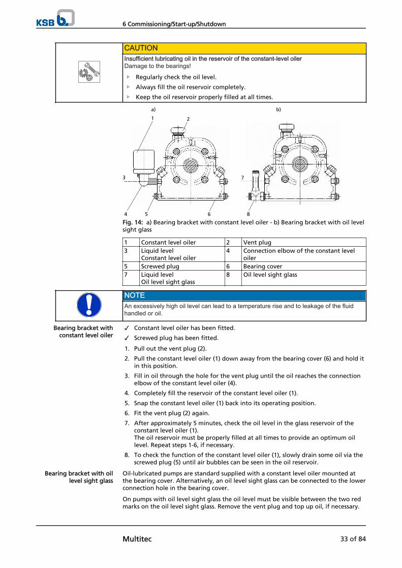
CAUTIONInsufficient lubricating oil in the reservoir of the constant-level oilerDamage to the bearings!
▷ Regularly check the oil level.
▷ Always fill the oil reservoir completely.
▷ Keep the oil reservoir properly filled at all times.
1
a) b)
2
4
3
5 6 8
7
Fig. 14: a) Bearing bracket with constant level oiler - b) Bearing bracket with oil levelsight glass
1 Constant level oiler 2 Vent plug3 Liquid level
Constant level oiler4 Connection elbow of the constant level
oiler5 Screwed plug 6 Bearing cover7 Liquid level
Oil level sight glass8 Oil level sight glass
NOTEAn excessively high oil level can lead to a temperature rise and to leakage of the fluidhandled or oil.
✓ Constant level oiler has been fitted.
✓ Screwed plug has been fitted.
1. Pull out the vent plug (2).
2. Pull the constant level oiler (1) down away from the bearing cover (6) and hold itin this position.
3. Fill in oil through the hole for the vent plug until the oil reaches the connectionelbow of the constant level oiler (4).
4. Completely fill the reservoir of the constant level oiler (1).
5. Snap the constant level oiler (1) back into its operating position.
6. Fit the vent plug (2) again.
7. After approximately 5 minutes, check the oil level in the glass reservoir of theconstant level oiler (1). The oil reservoir must be properly filled at all times to provide an optimum oillevel. Repeat steps 1-6, if necessary.
8. To check the function of the constant level oiler (1), slowly drain some oil via thescrewed plug (5) until air bubbles can be seen in the oil reservoir.
Oil-lubricated pumps are standard supplied with a constant level oiler mounted atthe bearing cover. Alternatively, an oil level sight glass can be connected to the lowerconnection hole in the bearing cover.
On pumps with oil level sight glass the oil level must be visible between the two redmarks on the oil level sight glass. Remove the vent plug and top up oil, if necessary.
Bearing bracket withconstant level oiler
Bearing bracket with oillevel sight glass
6 Commissioning/Start-up/Shutdown
Multitec 33 of 84
6.1.3 Priming and venting the pump
DANGERAn explosive atmosphere forms inside the pumpExplosion hazard!
▷ Before starting up the pump, vent the suction line and the pump and primewith the fluid to be handled.
CAUTIONIncreased wear due to dry runningDamage to the pump set!
▷ Never operate the pump set without liquid fill.
▷ Never close the shut-off element in the suction line and/or supply line duringpump operation.
1 2
5
43
6Fig. 15: Vacuum balance line
1 Vessel under vacuum 2 Vacuum balance line3 Shut-off element 4 Swing check valve5 Main shut-off element 6 Vacuum-tight shut-off element
1. Vent the pump and suction line and prime with the fluid to be handled.For venting use the various plugged drain holes provided on the pump and anyventing devices provided in the pipelines.
2. Fully open the shut-off element in the suction line.
3. Fully open all auxiliary feed lines (barrier fluid, flushing liquid, etc), if applicable.
4. Open the shut-off element (3), if any, in the vacuum balance line (2) and closethe vacuum-tight shut-off element (6), if any.
NOTEFor design-inherent reasons a remaining gas volume in the hydraulic system cannot beexcluded after the pump has been primed for commissioning/start-up. However, once themotor is started up the pumping effect will immediately fill this volume with the fluidhandled.
6 Commissioning/Start-up/Shutdown
34 of 84 Multitec
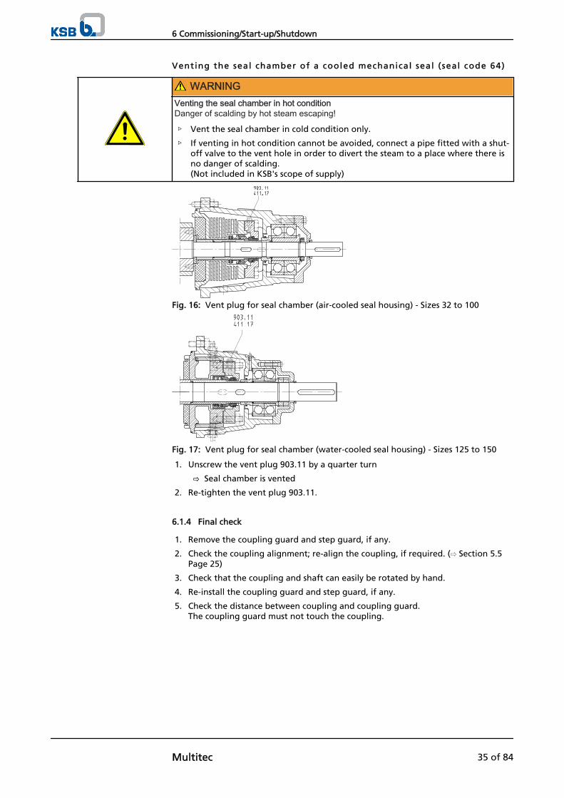
Venting the seal chamber of a cooled mechanical seal ( seal code 64)
WARNINGVenting the seal chamber in hot conditionDanger of scalding by hot steam escaping!
▷ Vent the seal chamber in cold condition only.
▷ If venting in hot condition cannot be avoided, connect a pipe fitted with a shut-off valve to the vent hole in order to divert the steam to a place where there isno danger of scalding.(Not included in KSB's scope of supply)
Fig. 16: Vent plug for seal chamber (air-cooled seal housing) - Sizes 32 to 100
Fig. 17: Vent plug for seal chamber (water-cooled seal housing) - Sizes 125 to 150
1. Unscrew the vent plug 903.11 by a quarter turn
⇨ Seal chamber is vented
2. Re-tighten the vent plug 903.11.
6.1.4 Final check
1. Remove the coupling guard and step guard, if any.
2. Check the coupling alignment; re-align the coupling, if required. (⇨ Section 5.5Page 25)
3. Check that the coupling and shaft can easily be rotated by hand.
4. Re-install the coupling guard and step guard, if any.
5. Check the distance between coupling and coupling guard.The coupling guard must not touch the coupling.
6 Commissioning/Start-up/Shutdown
Multitec 35 of 84
6.1.5 Start-up
DANGERThe permissible pressure and temperature limits will be exceeded if the pump isoperated with the suction and discharge lines closed.Explosion hazard!Leakage of hot or toxic fluids!
▷ Never operate the pump with the shut-off elements in the suction line and/ordischarge line closed.
▷ Only start up the pump set with the discharge side gate valve slightly or fullyopen.
DANGERExcessive temperatures due to dry running or excessive gas content in the fluid handledExplosion hazard!Damage to the pump set!
▷ Never operate the pump set without liquid fill.
▷ Prime the pump as specified. (⇨ Section 6.1.3 Page 34)
▷ Always operate the pump within the permissible operating range.
CAUTIONAbnormal noises, vibrations, temperatures or leakageDamage to the pump!
▷ Switch off the pump (set) immediately.
▷ Eliminate the causes before returning the pump set to service.
✓ The system piping has been cleaned.
✓ Pump, suction line and inlet tank, if any, have been vented and primed with thefluid handled.
✓ The lines for priming and venting have been closed.
CAUTIONStart-up against open discharge lineMotor overload!
▷ Make sure the motor has a sufficient power reserve.
▷ Use a soft starter.
▷ Use speed control.
1. Fully open the shut-off element in the suction head/suction lift line.
2. Close or slightly open the shut-off element in the discharge line.
3. Switch on the motor.Start-up must proceed without abnormal vibrations or noises.
4. Immediately after the pump has reached full rotational speed, slowly open theshut-off element in the discharge line and adjust it to comply with the dutypoint.An automatic check valve installed must open steadily when the operating speedhas been reached, without abnormal noise, vibrations or increased powerconsumption of the pump set.
5. After the duty point has been reached, check motor input power and bearingtemperature.
6. After the operating temperature has been reached and/or in the event ofleakage, switch off the pump set and re-tighten the bolts between lantern andcasing.
7. Check the coupling alignment. Re-align the coupling if required.
6 Commissioning/Start-up/Shutdown
36 of 84 Multitec
6.1.6 Checking the shaft seal
The mechanical seal only leaks slightly or invisibly (as vapour) during operation.Mechanical seals are maintenance-free.
The packed gland must leak slightly during operation.
(approx. 20 drops per minute)
NOTEOn variable-speed pumps, the necessary gland packing leakage must be set for theminimum fluid pressure; higher leakage rates are to be expected for other operatingconditions.
Adjust ing the leakage
1. Only lightly tighten the nuts of the gland follower by hand.
2. Use a feeler gauge to verify that the gland follower is mounted centred and at aright angle to the shaft.
⇨ The gland must leak after the pump has been primed.
The leakage can be reduced.
1. Tighten the nuts of the gland follower by 1/6 turn.
2. Monitor the leakage for another five minutes.
Excessive leakage:Repeat steps 1 and 2 until the minimum value has been reached.
Not enough leakage:Slightly loosen the nuts at the gland follower.
No leakage:Switch off the pump set immediately!Loosen the gland follower and repeat start-up.
Checking the leakage
After the leakage has been adjusted, monitor the leakage for about two hours atmaximum fluid temperature. Check that enough leakage occurs at the gland at minimum fluid pressure.
6.1.7 Shutdown
CAUTIONHeat build-up inside the pumpDamage to the shaft seal!
▷ Depending on the type of installation, the pump set requires sufficient after-runtime – with the heat source switched off – until the fluid handled has cooleddown.
✓ The shut-off element in the suction line is and remains open.
1. Close the shut-off element in the discharge line.
2. Switch off the motor and make sure the pump set runs down smoothly to astandstill.
NOTEIf the discharge line is equipped with a non-return or check valve, the shut-off elementmay remain open if there is back pressure.
For prolonged shutdown periods:
1. Close the shut-off element in the suction line.
2. Close the auxiliary connections. If the fluid handled is fed in under vacuum, also supply the shaft seal with barrierfluid during standstill.
Mechanical seal
Gland packing
Prior to commissioning
After five minutes ofoperation
6 Commissioning/Start-up/Shutdown
Multitec 37 of 84
CAUTIONRisk of freezing during prolonged pump shutdown periodsDamage to the pump!
▷ Drain the pump and the cooling/heating chambers (if any) or otherwise protectthem against freezing.
6.2 Operating limits
DANGERNon-compliance with application limits for pressure, temperature and speedExplosion hazard!Hot or toxic fluid may escape!
▷ Comply with the operating data indicated in the data sheet.
▷ Avoid prolonged operation against a closed shut-off element.
▷ Never operate the pump at temperatures exceeding those specified in the datasheet or on the name plate unless the written consent of the manufacturer hasbeen obtained.
6.2.1 Ambient temperature
Observe the following parameters and values during operation:
Table 12: Permissible ambient temperatures
Permissible ambient temperature ValueMaximum 40 ℃Minimum on request
CAUTIONOperation outside the permissible ambient temperatureDamage to the pump (set)!
▷ Observe the specified limits for permissible ambient temperatures.
6.2.2 Frequency of starts
DANGERExcessive surface temperature of the motorExplosion hazard!Damage to the motor!
▷ In case of explosion-proof motors, observe the frequency of starts specified inthe manufacturer's product literature.
CAUTIONRe-start while motor is still running downDamage to the pump (set)!
▷ Do not re-start the pump set before the pump rotor has come to a standstill.
The frequency of starts is usually determined by the maximum temperature increaseof the motor. This largely depends on the power reserves of the motor in steady-state operation and on the starting conditions (d.o.l., star-delta, moments of inertia,etc). If the start-ups are evenly spaced over the period indicated, the following limitscan be used for orientation for start-up with the discharge-side gate valve slightlyopen:
6 Commissioning/Start-up/Shutdown
38 of 84 Multitec
Table 13: Frequency of starts
Motor rating [kW]
Maximum No. of start-ups [Start-ups/hour]
up to 3 204 to 11 1511 to 45 10
45 and above 5
Overloading of the motor may generally result in:
▪ An abnormal increase in motor temperature exceeding the temperature limit ofthe winding or bearing grease
▪ Premature coupling wear
▪ Reduced service life of the pump components
▪ Irregularities or malfunctions in the system
6.2.3 Flow rate
The minimum flows indicated below are for single pump operation and will preventthermal or mechanical overloading of the pump. In case of parallel operation withpumps of identical or different design higher flow rates may be required in somecases, to guarantee a stable operating behaviour.
Table 14: Flow rate
Pump size Temperature range (t) Min. flow rate Max. flow rate32
50
65
-10 to +100 °C ≈ 15 % of QOpt4) see hydraulic
curves> 100 to +140 °C ≈ 20 % of QOpt4)
> 140 to +200 °C ≈ 25 % of QOpt4)
100
125
150
independent oftemperature
≈ 35 % von QOpt4)
In addition, a temporary minimum flow of 25 % of QOpt has been defined for pumpsizes 100, 125 and 150 4) . This temporary flow shall be limited to one hour'suninterrupted operation and approx. 200 hours/year.
The calculation formula below can be used to check if an additional heat build-upcould lead to a dangerous temperature increase at the pump surface.
Table 15: Key
Symbol Description Unitc Specific heat capacity J/kg Kg Gravitational constant m/s²H Pump head mTf Temperature of the fluid handled °C
To Temperature at the casing surface °C
Pump efficiency at duty point -Temperature difference °C
6.2.4 Density of the fluid handled
The power input of the pump increases in proportion to the density of the fluidhandled.
4) Best efficiency point
6 Commissioning/Start-up/Shutdown
Multitec 39 of 84
CAUTIONExcessive density of the fluid handledMotor overload!
▷ Observe the information on fluid density indicated in the data sheet.
▷ Make sure the power reserve of the motor is sufficient.
6.2.5 Abrasive fluids
Do not exceed the maximum permissible solids content specified in the data sheet.When the pump handles fluids containing abrasive substances, increased wear of thehydraulic system and the shaft seal are to be expected. In this case, reduce theintervals commonly recommended for servicing and maintenance.
6.3 Shutdown/storage/preservation
6.3.1 Measures to be taken for shutdown
The pump (set) remains instal led
✓ Sufficient fluid is supplied for the operation check run of the pump.
1. Start up the pump (set) regularly once a month or once every three months forapproximately five minutes during prolonged shutdown periods. This will prevent the formation of deposits within the pump and the pumpintake area.
NOTEProlonged shutdown periods should be avoided in the case of pumps in material variants10, 13, 17, 20, 21 and 27 (cast-iron hydraulics), particularly if the pumps are handlingaggressive water qualities (high oxygen content). In such cases, the pump should remainfilled, and the operation check run should be performed at least every other day.
NOTEThe stage casings of horizontal pumps can only be drained completely through the drainplugs provided on the stage casings (optional). If this is not possible we recommend toproceed as described in the following section.
The pump (set) i s removed from the pipe and stored
✓ The pump has been properly drained (⇨ Section 7.3 Page 48) and the safetyinstructions for dismantling the pump have been observed .
1. Fill the pump with a water-repellent preservative (e.g. RUSTELO DEWATERING924, producer: CASTROL; OSYRIS DW, producer: TOTAL; or equivalent).
2. Turn the pump rotor by hand several times, to ensure even distribution of thepreservative.
CAUTIONGlycol-base preservatives (e.g. KLÜBERTOP K 01-601)Corrosion damage on surfaces not treated with preservative
▷ Do not drain the preservative if the pump is stored for a longer period.
▷ Completely fill the pump with preservative for storage.
▷ Do not drain the preservative until immediately before the pump is returned toservice.(Preservative can be re-used if water content < 20%)
3. Drain the pump and close the suction and discharge nozzle, respectively.
4. Oil or grease all blank parts and surfaces of the pump (with silicone-free oil orgrease) to protect them against corrosion.
6 Commissioning/Start-up/Shutdown
40 of 84 Multitec
Observe any additional instructions and information provided. (⇨ Section 3.2Page 13)
6.4 Returning to service after storage
For returning the pump to service observe the sections on commissioning/start-up (⇨Section 6.1 Page 32) and the operating limits (⇨ Section 6.2 Page 38) .
In addition, carry out all servicing/maintenance operations before returning thepump (set) to service. (⇨ Section 7 Page 42)
WARNINGFailure to re-install or re-activate protective devicesRisk of personal injury from moving parts or escaping fluid!
▷ As soon as the work is complete, re-install and/or re-activate any safety-relevantand protective devices.
NOTEIf the pump has been out of service for more than one year, replace all elastomer seals.
6 Commissioning/Start-up/Shutdown
Multitec 41 of 84
7 Servicing/Maintenance
7.1 Safety regulations
DANGERImproperly serviced pump setExplosion hazard!Damage to the pump set!
▷ Service the pump set regularly.
▷ Prepare a maintenance schedule with special emphasis on lubricants, shaft sealand coupling.
The operator ensures that all maintenance, inspection and installation work isperformed by authorised, qualified specialist personnel who are thoroughly familiarwith the manual.
WARNINGPump set started up inadvertentlyRisk of injury by moving parts!
▷ Always make sure the electrical connections are disconnected before carryingout work on the pump set.
▷ Make sure that the pump set cannot be switched on accidentally.
WARNINGFluids posing a health hazard or hot fluidsRisk of personal injury!
▷ Observe all relevant laws.
▷ When draining the fluid take appropriate measures to protect persons and theenvironment.
▷ Decontaminate pumps handling fluids posing a health hazard.
A regular maintenance schedule will help avoid expensive repairs and contribute totrouble-free, reliable operation of the pump (set) with a minimum of maintenanceexpenditure and work.
NOTEAll maintenance, service and installation work can be carried out by KSB Service. Findyour contact in the attached "Addresses" booklet or on the Internet at www.ksb.com/contact".
Never use force when dismantling and reassembling a pump set.
7.2 Servicing/inspection
7.2.1 Supervision of operation
DANGERAn explosive atmosphere forms inside the pumpExplosion hazard!
▷ The pump internals in contact with the fluid to be handled, including the sealchamber and auxiliary systems must be filled with the fluid to be handled at alltimes.
▷ Provide sufficient inlet pressure.
▷ Provide an appropriate monitoring system.
7 Servicing/Maintenance
42 of 84 Multitec
DANGERIncorrectly serviced shaft sealExplosion hazard!Fire hazard!Leakage of hot, toxic fluids!Damage to the pump set!
▷ Regularly service the shaft seal.
DANGERExcessive temperatures as a result of bearings running hot or defective bearing sealsExplosion hazard!Fire hazard!Damage to the pump set!
▷ Regularly check the lubricant level.
▷ Regularly check the rolling element bearings for running noises.
CAUTIONIncreased wear due to dry runningDamage to the pump set!
▷ Never operate the pump set without liquid fill.
▷ Never close the shut-off element in the suction line and/or supply line duringpump operation.
CAUTIONExcessive fluid temperatureDamage to the pump!
▷ Prolonged operation against a closed shut-off element is not permitted (heatingup of the fluid).
▷ Observe the temperature limits in the data sheet and in the section onOperating limits. (⇨ Section 6.2 Page 38)
While the pump is in operation, observe and check the following:
▪ The pump must run quietly and free from vibrations at all times.
▪ In case of oil lubrication, ensure the oil level is correct. (⇨ Section 6.1.2 Page 32)
▪ Check the shaft seal. (⇨ Section 6.1.6 Page 37)
▪ Check the static seals for any leakage.
▪ Check the rolling element bearings for running noises.Vibrations, noise and an increase in current input occurring during unchangedoperating conditions indicate wear.
▪ Check the correct functioning of any auxiliary connections.
▪ Monitor the stand-by pump.To make sure that the stand-by pumps are ready for operation, start them uponce a week.
▪ Monitor the bearing temperature.The bearing temperature must not exceed 90 °C (measured on the outside of thebearing bracket).
▪ On oil-lubricated models the bearing temperature can be measured in the oilsump. The alert limit is 100 °C. Never exceed 110 °C (pump trip).
7 Servicing/Maintenance
Multitec 43 of 84
CAUTIONOperation outside the permissible bearing temperatureDamage to the pump!
▷ The bearing temperature of the pump (set) must never exceed 90 °C (measuredon the outside of the bearing bracket).
NOTEAfter commissioning, increased temperatures may occur at grease-lubricated rollingelement bearings due to the running-in process. The final bearing temperature is onlyreached after a certain period of operation (up to 48 h depending on the conditions).
Please note the following when checking the bearing temperature:
▪ Manual temperature checks are not sufficient !
▪ If the bearing temperature exceeds 100 °C during start-up, switch off the pumpand check the following:
– Check the alignment of the pump set.
– Verify bearing type and arrangement. (⇨ Section 7.5.4 Page 67)
– Remove the rolling element bearings.
– Check the grease quantity in the rolling element bearings (grease-lubricatedbearings only).Excessive amounts of grease will cause increased temperatures.
– After reassembly, ensure a tight press fit of the outer bearing race via thecover (fixed bearing).
– A temperature rise may also occur after replacement of the bearings ordismantling of the hydraulic system.
7.2.2 Inspection work
DANGERExcessive temperatures caused by friction, impact or frictional sparksExplosion hazard!Fire hazard!Damage to the pump set!
▷ Regularly check the coupling guard, plastic components and other guards ofrotating parts for deformation and sufficient distance from rotating parts.
7.2.2.1 Checking the coupling
Check the flexible elements of the coupling. Replace these parts in due time if thereis any sign of wear.
7.2.2.2 Checking the clearance gaps
Excessive clearances will affect pump performance. Losses in efficiency and dischargehead will occur.
Max. c learance gaps
The clearances given refer to the diameter.
Table 16: Max. permissible clearance gaps
Diameter Clearance gap [mm]
Impellers 230 and 231 Suction-side clearance gap 0.8Clearance gap at the hub 0.8
7 Servicing/Maintenance
44 of 84 Multitec
Diameter Clearance gap [mm]
Balance drum 59.4 0.8Suction casing 106.1 and spacer sleeve525.2(installation types C and D only)
1.0 if the fluid is pumped from a vesselunder vacuum conditions2.5 for all other operating conditions
NOTEIf the clearances given are exceeded by more than 1 mm (referring to the diameter)replace the affected components or restore the original clearance by means of a casingwear ring. Contact KSB.
7.2.2.3 Cleaning filters
CAUTIONInsufficient inlet pressure due to clogged filter in the suction lineDamage to the pump!
▷ Monitor contamination of filter with suitable means (e.g. differential pressuregauge).
▷ Clean filter in appropriate intervals.
7.2.2.4 Checking the bearing seals
DANGERExcessive temperatures caused by mechanical contactRisk of explosion!Damage to the pump set!
▷ Check correct seating of axial sealing rings mounted on the shaft.Only gentle contact of the sealing lip shall be established.
7.2.3 Lubrication and lubricant change of rolling element bearings
DANGERExcessive temperatures as a result of bearings running hot or defective bearing sealsExplosion hazard!Fire hazard!Damage to the pump set!
▷ Regularly check the condition of the lubricant.
7.2.3.1 Oil lubrication
The rolling element bearings are usually lubricated with mineral oil.
7 Servicing/Maintenance
Multitec 45 of 84
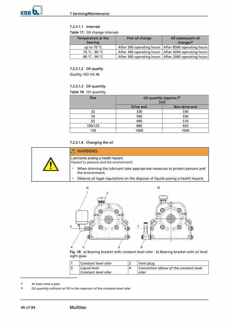
7.2.3.1.1 Intervals
Table 17: Oil change intervals
Temperature at thebearing
First oil change All subsequent oilchanges5)
up to 70 ℃ After 300 operating hours After 8500 operating hours70 °C - 80 °C After 300 operating hours After 4200 operating hours80 °C - 90 °C After 300 operating hours After 2000 operating hours
7.2.3.1.2 Oil quality
Quality: ISO VG 46
7.2.3.1.3 Oil quantity
Table 18: Oil quantity
Size Oil quantity (approx.)6)
[ml]Drive end Non-drive end
32 330 33050 500 33065 490 510
100/125 880 920150 1000 1040
7.2.3.1.4 Changing the oil
WARNINGLubricants posing a health hazardHazard to persons and the environment!
▷ When draining the lubricant take appropriate measures to protect persons andthe environment.
▷ Observe all legal regulations on the disposal of liquids posing a health hazard.
1
a) b)
2
4
3
5 6 8
7
Fig. 18: a) Bearing bracket with constant level oiler - b) Bearing bracket with oil levelsight glass
1 Constant level oiler 2 Vent plug3 Liquid level
Constant level oiler4 Connection elbow of the constant level
oiler
5) At least once a year6) Oil quantity without oil fill in the reservoir of the constant-level oiler
7 Servicing/Maintenance
46 of 84 Multitec
5 Screwed plug 6 Bearing cover7 Liquid level
Oil level sight glass8 Oil level sight glass
✓ A suitable container for the used oil is on hand.
1. Place the container underneath the screwed plug.
2. Undo the screwed plug (5) at the bearing cover (6) and drain the oil.
3. Once the bearing housing (3) has been drained, re-insert and re-tighten thescrewed plug (5).
4. Re-fill with oil. (⇨ Section 6.1.2 Page 32)
7.2.3.2 Grease lubrication
The bearings are supplied packed with high-quality lithium-soap grease.
7.2.3.2.1 Intervals
Depending on the pump size and rotational speed, re-lubricate the rolling elementbearings at regular intervals or replace the grease in the rolling element bearings.
Exception: bearings sealed for life (Multitec 32 and non-drive end rolling elementbearings on Multitec 50 and 65)
NOTEOn some pump designs the rolling element bearings are lubricated for life. These pumpsare not provided with a lubricating nipple on the bearing bracket.
Size Rotational speed in min-1
< 1800 ≈ 2950 ≈ 3550325065
10000 h 7200 h 5700 h
100125
9000 h 5700 h 3900 h
150 8300 h 4000 h 3100 h
NOTEIf re-lubrication intervals are short, we recommend to completely replace the grease oncea year.Otherwise, the grease fill must be replaced completely every two years. To do so,remove the rolling element bearings, clean and pack with new grease.
7.2.3.2.2 Grease quality
Optimum grease propert ies for rol l ing element bear ings
▪ High melting point lithium soap base grease
▪ Free of resin and acid
▪ Not liable to crumble
▪ With good rust-preventive characteristics
▪ Penetration number between 2 and 3 (corresponding to a worked penetration of220 to 295 mm/10)
▪ Drop point ≥ 175 °C
If required, the bearings may be lubricated with greases of other soap bases.Make sure to remove any old grease and rinse the bearings thoroughly.
7 Servicing/Maintenance
Multitec 47 of 84
7.2.3.2.3 Grease quantity
Table 19: Grease quantity
Pump size Quantity per bearing unit [g]
Drive end Non-drive end32 - -
50/65 15 -100/125 25 15
150 40 30
7.2.3.2.4 Changing the grease
CAUTIONMixing greases of differing soap basesChanged lubricating qualities!
▷ Thoroughly clean the bearings.
▷ Adjust the re-lubrication intervals to the grease used.
1. Only half-fill the bearing cavities with grease.
7.3 Drainage/disposal
WARNINGFluids posing a health hazardHazardous to persons and the environment!
▷ Collect and properly dispose of flushing liquid and any fluid residues.
▷ Wear safety clothing and a protective mask, if required.
▷ Observe all legal regulations on the disposal of fluids posing a health hazard.
Vert ical pumps
Remove the drain plugs in the suction casing.
Horizontal pumps
Remove the drain plugs in the stage casing (optional), suction casing (if any) anddischarge casing.
Alternative:
1. Use a crane to bring the pump into a vertical position, with the suction nozzlepointing downwards.
2. Turn the rotor by hand.
3. Remove the drain plugs in the seal housing, suction casing (if any) and dischargecasing.
If the pump cannot be drained completely, we recommend to dismantle it and drythe individual components.
7.4 Dismantling the pump set
7.4.1 General information/Safety regulations
WARNINGUnqualified personnel performing work on the pump (set)Risk of personal injury!
▷ Always have repair and maintenance work performed by specially trained,qualified personnel.
7 Servicing/Maintenance
48 of 84 Multitec
WARNINGHot surfaceRisk of personal injury!
▷ Allow the pump set to cool down to ambient temperature.
CAUTIONProtruding plain bearings on sizes 32, 50 and 100Damage to plain bearings when dismantling the suction line!
▷ When separating the suction line from the suction nozzle, make sure to shiftthe suction line axially away from the pump by at least 20 mm before removingit.
Observe the general safety instructions and information. (⇨ Section 7.1 Page 42)
For any work on the motor, observe the instructions of the relevant motormanufacturer.
For dismantling and reassembly observe the exploded views and the generalassembly drawing. (⇨ Section 9.1 Page 75)
NOTEAll maintenance, service and installation work can be carried out by KSB Service. Findyour contact in the attached "Addresses" booklet or on the Internet at www.ksb.com/contact".
DANGERInsufficient preparation of work on the pump (set)Risk of personal injury!
▷ Properly shut down the pump set. (⇨ Section 6.1.7 Page 37)
▷ Close the shut-off elements in the suction and discharge line.
▷ Drain the pump and release the pump pressure. (⇨ Section 7.3 Page 48)
▷ Close any auxiliary connections.
▷ Allow the pump set to cool down to ambient temperature.
NOTEAfter a prolonged period of operation the individual parts may be hard to pull off theshaft. If this is the case, use a brand name penetrating agent and/or - if possible - anappropriate pull-off device.
7.4.2 Preparing the pump set
1. Disconnect the power supply (e.g. at the motor).
2. Disconnect and remove all auxiliary pipework.
3. Remove the coupling guard.
4. Remove the coupling spacer, if any.
5. Drain the oil fill of oil-lubricated bearings.
7.4.3 Dismantling the bearings
7.4.3.1 Dismantling the plain bearing (non-drive end)
The plain bearing is removed without dismantling the hydraulic section of the pump.
7 Servicing/Maintenance
Multitec 49 of 84
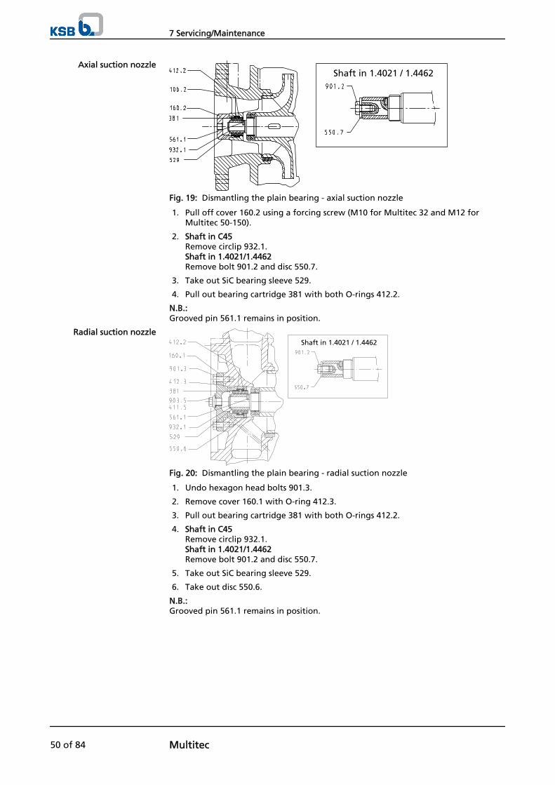
Shaft in 1.4021 / 1.4462
Fig. 19: Dismantling the plain bearing - axial suction nozzle
1. Pull off cover 160.2 using a forcing screw (M10 for Multitec 32 and M12 forMultitec 50-150).
2. Shaft in C45Remove circlip 932.1.Shaft in 1.4021/1.4462 Remove bolt 901.2 and disc 550.7.
3. Take out SiC bearing sleeve 529.
4. Pull out bearing cartridge 381 with both O-rings 412.2.
N.B.:Grooved pin 561.1 remains in position.
Shaft in 1.4021 / 1.4462
Fig. 20: Dismantling the plain bearing - radial suction nozzle
1. Undo hexagon head bolts 901.3.
2. Remove cover 160.1 with O-ring 412.3.
3. Pull out bearing cartridge 381 with both O-rings 412.2.
4. Shaft in C45Remove circlip 932.1.Shaft in 1.4021/1.4462 Remove bolt 901.2 and disc 550.7.
5. Take out SiC bearing sleeve 529.
6. Take out disc 550.6.
N.B.:Grooved pin 561.1 remains in position.
Axial suction nozzle
Radial suction nozzle
7 Servicing/Maintenance
50 of 84 Multitec
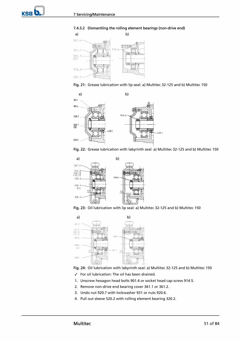
7.4.3.2 Dismantling the rolling element bearings (non-drive end)
a) b)
Fig. 21: Grease lubrication with lip seal: a) Multitec 32-125 and b) Multitec 150
a) b)
Fig. 22: Grease lubrication with labyrinth seal: a) Multitec 32-125 and b) Multitec 150
a) b)
Fig. 23: Oil lubrication with lip seal: a) Multitec 32-125 and b) Multitec 150
a) b)
Fig. 24: Oil lubrication with labyrinth seal: a) Multitec 32-125 and b) Multitec 150
✓ For oil lubrication: The oil has been drained.
1. Unscrew hexagon head bolts 901.4 or socket head cap screw 914.5.
2. Remove non-drive end bearing cover 361.1 or 361.2.
3. Undo nut 920.7 with lockwasher 931 or nuts 920.6.
4. Pull out sleeve 520.2 with rolling element bearing 320.2.
7 Servicing/Maintenance
Multitec 51 of 84

7.4.3.3 Dismantling the rolling element bearings (drive end)
The drive-end rolling element bearings are removed without dismantling the plainbearings located at the opposite end of the shaft.
Dismantl ing the coupl ing half
The coupling half must be removed before the drive-end rolling element bearingscan be dismantled.
1. Undo the grub screw in the coupling hub.
2. Pull off the coupling half.
3. Pull out key 940.3.
Preparat ions for dismantl ing the rol l ing element bearings
Grease lubrication
a) b) c)
d)
Fig. 25: Grease lubrication: a) Size 32 and b) Size 50-65 and c) Size 100-150 andd) Installation type V of size 100-150
1. Remove joint ring (V-ring) 411.7.
2. Undo hexagon head bolts 901.1.
3. Remove bearing cover 360.1.
a) b) c)
Fig. 26: Grease lubrication with labyrinth seal: a) Size 32 and b) Size 50-65 and c)Size 100-150
1. Remove labyrinth ring 423.2.
2. Undo hexagon head bolt 901.1.
3. Remove bearing cover 360.1.
Oil lubrication with lip seal
7 Servicing/Maintenance
52 of 84 Multitec
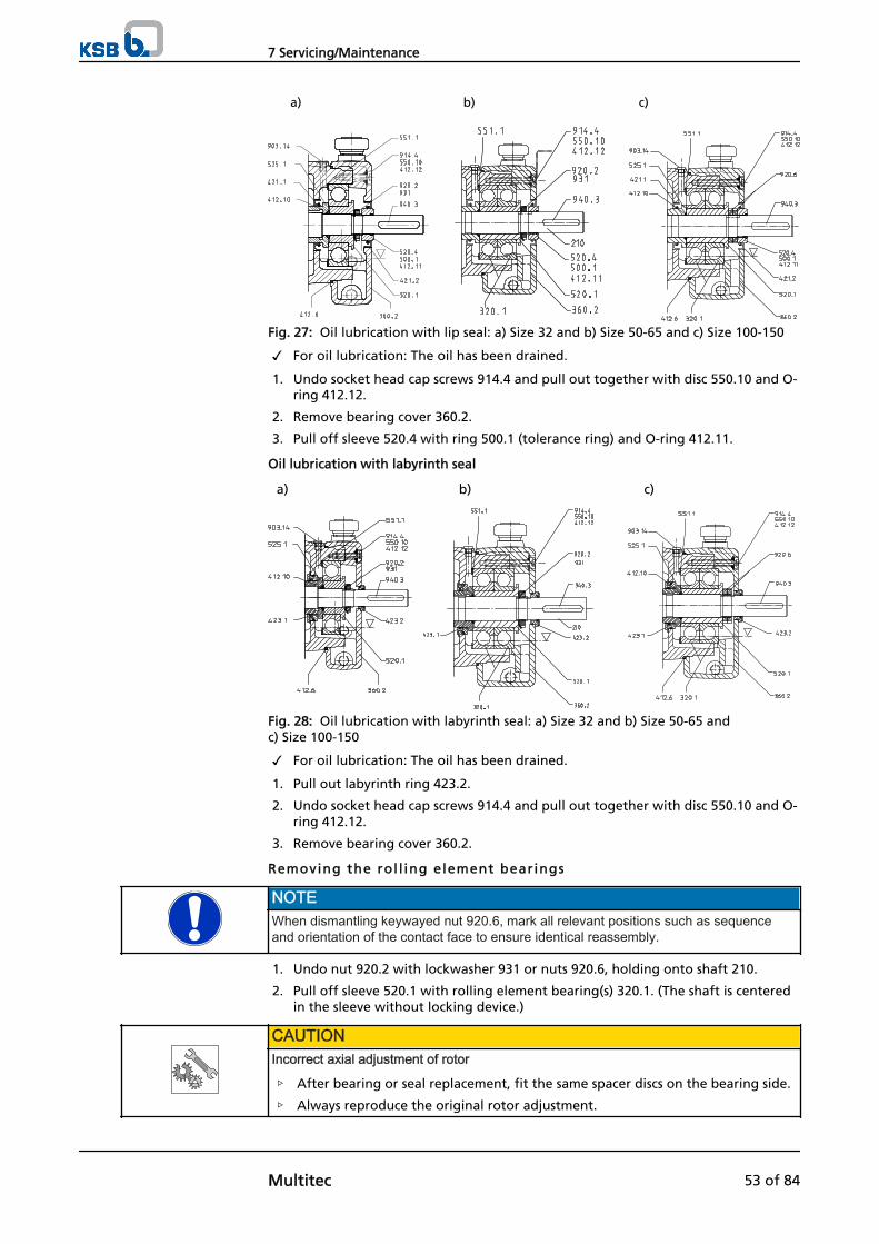
b) c)a)
Fig. 27: Oil lubrication with lip seal: a) Size 32 and b) Size 50-65 and c) Size 100-150
✓ For oil lubrication: The oil has been drained.
1. Undo socket head cap screws 914.4 and pull out together with disc 550.10 and O-ring 412.12.
2. Remove bearing cover 360.2.
3. Pull off sleeve 520.4 with ring 500.1 (tolerance ring) and O-ring 412.11.
Oil lubrication with labyrinth seal
b) c)a)
Fig. 28: Oil lubrication with labyrinth seal: a) Size 32 and b) Size 50-65 andc) Size 100-150
✓ For oil lubrication: The oil has been drained.
1. Pull out labyrinth ring 423.2.
2. Undo socket head cap screws 914.4 and pull out together with disc 550.10 and O-ring 412.12.
3. Remove bearing cover 360.2.
Removing the rol l ing element bearings
NOTEWhen dismantling keywayed nut 920.6, mark all relevant positions such as sequenceand orientation of the contact face to ensure identical reassembly.
1. Undo nut 920.2 with lockwasher 931 or nuts 920.6, holding onto shaft 210.
2. Pull off sleeve 520.1 with rolling element bearing(s) 320.1. (The shaft is centeredin the sleeve without locking device.)
CAUTIONIncorrect axial adjustment of rotor
▷ After bearing or seal replacement, fit the same spacer discs on the bearing side.
▷ Always reproduce the original rotor adjustment.
7 Servicing/Maintenance
Multitec 53 of 84
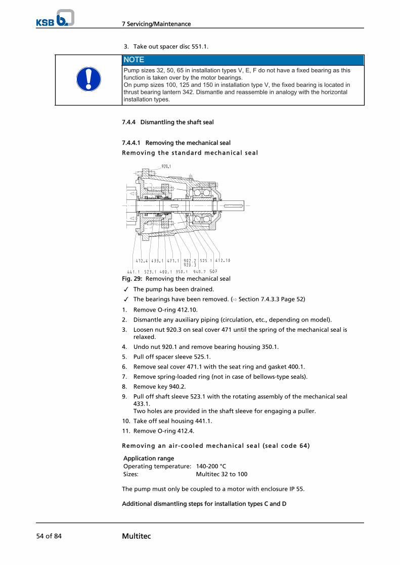
3. Take out spacer disc 551.1.
NOTEPump sizes 32, 50, 65 in installation types V, E, F do not have a fixed bearing as thisfunction is taken over by the motor bearings.On pump sizes 100, 125 and 150 in installation type V, the fixed bearing is located inthrust bearing lantern 342. Dismantle and reassemble in analogy with the horizontalinstallation types.
7.4.4 Dismantling the shaft seal
7.4.4.1 Removing the mechanical seal
Removing the standard mechanical seal
Fig. 29: Removing the mechanical seal
✓ The pump has been drained.
✓ The bearings have been removed. (⇨ Section 7.4.3.3 Page 52)
1. Remove O-ring 412.10.
2. Dismantle any auxiliary piping (circulation, etc., depending on model).
3. Loosen nut 920.3 on seal cover 471 until the spring of the mechanical seal isrelaxed.
4. Undo nut 920.1 and remove bearing housing 350.1.
5. Pull off spacer sleeve 525.1.
6. Remove seal cover 471.1 with the seat ring and gasket 400.1.
7. Remove spring-loaded ring (not in case of bellows-type seals).
8. Remove key 940.2.
9. Pull off shaft sleeve 523.1 with the rotating assembly of the mechanical seal433.1.Two holes are provided in the shaft sleeve for engaging a puller.
10. Take off seal housing 441.1.
11. Remove O-ring 412.4.
Removing an air -cooled mechanical seal ( seal code 64)
Application range Operating temperature: 140-200 °CSizes: Multitec 32 to 100
The pump must only be coupled to a motor with enclosure IP 55.
Additional dismantling steps for installation types C and D
7 Servicing/Maintenance
54 of 84 Multitec
Fig. 30: Removing an air-cooled mechanical seal - additional dismantling steps
1. Undo screw 900.2 and remove hood 683.1.
2. Undo axis 87-5 with fan impeller 831.1.Threaded insert 915 remains in shaft 210.
3. Remove support 59-7.
Fig. 31: Removing an air-cooled mechanical seal
✓ The pump has been drained.
✓ The bearings have been removed. (⇨ Section 7.4.3.3 Page 52)
1. Remove O-ring 412.10.
2. Pull off spacer sleeve 525.1.
3. Unscrew hexagon head bolt 901.11.
4. Undo nut 920.1 and remove bearing housing 350.1 with the lip seal.
5. Remove seal cover 471.1 with the seat ring and gasket 400.1.
6. Remove key 940.5.
7. Pull off shaft sleeve 523.1 with the rotating assembly of the mechanical seal433.7.Two holes are provided in the shaft sleeve for engaging a puller.
8. Take off seal housing 441.4.
9. Remove O-ring 412.4.
Installation types C and D
Dismantling sequence formechanical seal
7 Servicing/Maintenance
Multitec 55 of 84
Removing a water-cooled mechanical seal ( seal code 64)
Fig. 32: Removing a water-cooled mechanical seal
Application range Operating temperature: 140-200 ℃Pump sizes: Multitec 125 to 150
(optional for pump sizes Multitec 32 to 100)
✓ The pump has been drained.
✓ The cooling chamber has been drained.
✓ The bearings have been removed. (⇨ Section 7.4.3.3 Page 52)
1. Undo pipe union 731.15 and dismantle the cooling lines.
2. Remove the rolling element bearings. (⇨ Section 7.4.3.3 Page 52)
3. Remove O-ring 412.10.
4. Pull off spacer sleeve 525.1.
5. Undo nut 920.3 on seal cover 471.
6. Undo nut 920.1 and remove bearing housing 350.1 with the lip seal.
7. Remove seal cover 471.1 with the seat ring and gasket 400.1.
8. Remove key 940.5.
9. Pull off shaft sleeve 523.1 with the rotating assembly of the mechanical seal433.7.Two holes are provided in the shaft sleeve for engaging a puller.
10. Take off cooling jacket 66-2.
11. Take off seal housing 441.4.
12. Remove O-ring 412.4.
Removing a cartr idge-type mechanical seal
Cartridge-type mechanical seals are fitted in the seal arrangements specified by thecustomer. There is a wide variety of variants, types and brands. Please refer to thegeneral assembly drawing and the product literature supplied with the pump whendismantling these mechanical seal variants. If in doubt please contact themanufacturer.
7 Servicing/Maintenance
56 of 84 Multitec
Fig. 33: Removing a cartridge-type mechanical seal
The general procedure is as follows:
✓ The pump has been drained.
✓ The bearings have been removed. (⇨ Section 7.4.3.3 Page 52)
1. Remove O-ring 412.10.
2. Dismantle any auxiliary piping (circulation, etc., depending on model).
3. Undo nuts 920.3 at the cartridge.
4. Undo nut 920.1 and remove bearing housing 350.1.
5. Pull off spacer sleeve 525.1.
6. Take off cartridge 443.1 and gasket 400.1.
7. Remove key 940.2.
8. Pull off shaft protecting sleeve 523.6. Two holes are provided in the shaft sleeve for engaging a puller.
9. Take off seal housing 441.2 with O-ring 412.5 and two studs 902.2.
10. Remove O-ring 412.4.
Removing a double-act ing mechanical seal
Mechanical seals in tandem or back-to-back arrangement are fitted as per customerspecifications. There is a wide variety of variants, types and brands. Please refer tothe general assembly drawing and the product literature supplied with the pumpwhen dismantling these mechanical seal variants. If in doubt please contact themanufacturer.
The general procedure is as follows:
"Back to back" arrangement
7 Servicing/Maintenance
Multitec 57 of 84
Fig. 34: Removing a mechanical seal in back-to-back arrangement
✓ The pump has been drained.
✓ The bearings have been removed. (⇨ Section 7.4.3.3 Page 52)
1. Remove O-ring 412.10.
2. Dismantle the auxiliary piping (of thermosyphon system).
3. Undo pipe unions 731.8 and 731.9.
4. Loosen nuts 920.3 on seal cover 130.1 until the spring of the mechanical seal isrelaxed.
5. Undo nut 920.1 and remove bearing housing 350.1.
6. Pull off spacer sleeve 525.1.
7. Take off seal cover 130.1 with gasket 400.1.
8. Remove key 940.2.
9. Remove the spring-loaded ring.
10. Pull off shaft sleeve 523.4 with the rotating assembly of the second mechanicalseal 433.5.
11. Remove O-ring 412.8 (on Multitec 32: O-ring 412.4).
12. Pull off shaft protecting sleeve 523.5 (on Multitec 32: shaft protecting sleeve523.4) with first mechanical seal 433.6.
13. Take off seal housing 441.2 with O-ring 412.5 and two studs 902.2.
14. Remove O-ring 412.4.
Tandem or quench design
7 Servicing/Maintenance
58 of 84 Multitec
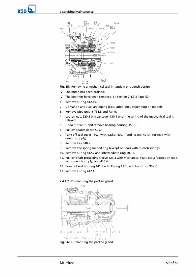
Fig. 35: Removing a mechanical seal in tandem or quench design
✓ The pump has been drained.
✓ The bearings have been removed. (⇨ Section 7.4.3.3 Page 52)
1. Remove O-ring 412.10.
2. Dismantle any auxiliary piping (circulation, etc., depending on model).
3. Remove pipe unions 731.8 and 731.9.
4. Loosen nuts 920.3 on seal cover 130.1 until the spring of the mechanical seal isrelaxed.
5. Undo nut 920.1 and remove bearing housing 350.1.
6. Pull off spacer sleeve 525.1.
7. Take off seal cover 130.1 with gasket 400.1 (and lip seal 421.4, for seals withquench supply).
8. Remove key 940.2.
9. Remove the spring-loaded ring (except on seals with quench supply).
10. Remove O-ring 412.7 and intermediate ring 509.1.
11. Pull off shaft protecting sleeve 523.3 with mechanical seals 433.3 (except on sealswith quench supply) and 433.4.
12. Take off seal housing 441.2 with O-ring 412.5 and two studs 902.2.
13. Remove O-ring 412.4.
7.4.4.2 Dismantling the packed gland
Fig. 36: Dismantling the packed gland
7 Servicing/Maintenance
Multitec 59 of 84
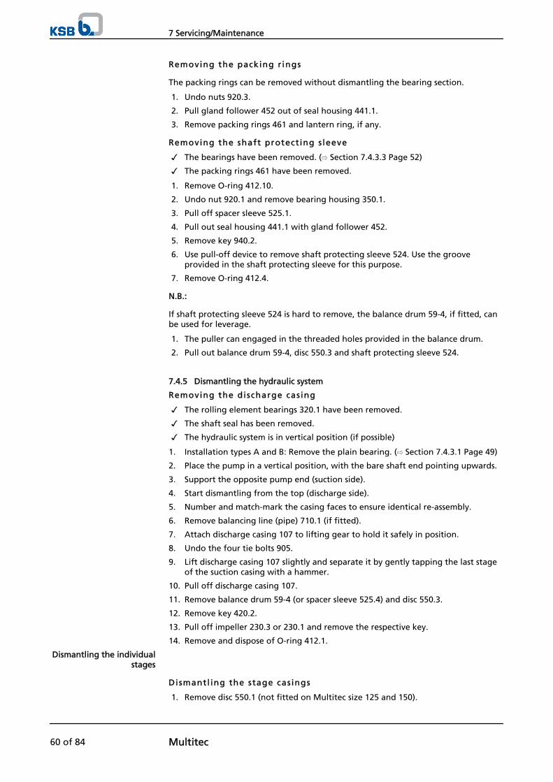
Removing the packing r ings
The packing rings can be removed without dismantling the bearing section.
1. Undo nuts 920.3.
2. Pull gland follower 452 out of seal housing 441.1.
3. Remove packing rings 461 and lantern ring, if any.
Removing the shaft protect ing s leeve
✓ The bearings have been removed. (⇨ Section 7.4.3.3 Page 52)
✓ The packing rings 461 have been removed.
1. Remove O-ring 412.10.
2. Undo nut 920.1 and remove bearing housing 350.1.
3. Pull off spacer sleeve 525.1.
4. Pull out seal housing 441.1 with gland follower 452.
5. Remove key 940.2.
6. Use pull-off device to remove shaft protecting sleeve 524. Use the grooveprovided in the shaft protecting sleeve for this purpose.
7. Remove O-ring 412.4.
N.B.:
If shaft protecting sleeve 524 is hard to remove, the balance drum 59-4, if fitted, canbe used for leverage.
1. The puller can engaged in the threaded holes provided in the balance drum.
2. Pull out balance drum 59-4, disc 550.3 and shaft protecting sleeve 524.
7.4.5 Dismantling the hydraulic system
Removing the discharge cas ing
✓ The rolling element bearings 320.1 have been removed.
✓ The shaft seal has been removed.
✓ The hydraulic system is in vertical position (if possible)
1. Installation types A and B: Remove the plain bearing. (⇨ Section 7.4.3.1 Page 49)
2. Place the pump in a vertical position, with the bare shaft end pointing upwards.
3. Support the opposite pump end (suction side).
4. Start dismantling from the top (discharge side).
5. Number and match-mark the casing faces to ensure identical re-assembly.
6. Remove balancing line (pipe) 710.1 (if fitted).
7. Attach discharge casing 107 to lifting gear to hold it safely in position.
8. Undo the four tie bolts 905.
9. Lift discharge casing 107 slightly and separate it by gently tapping the last stageof the suction casing with a hammer.
10. Pull off discharge casing 107.
11. Remove balance drum 59-4 (or spacer sleeve 525.4) and disc 550.3.
12. Remove key 420.2.
13. Pull off impeller 230.3 or 230.1 and remove the respective key.
14. Remove and dispose of O-ring 412.1.
Dismantl ing the stage cas ings
1. Remove disc 550.1 (not fitted on Multitec size 125 and 150).
Dismantling the individualstages
7 Servicing/Maintenance
60 of 84 Multitec
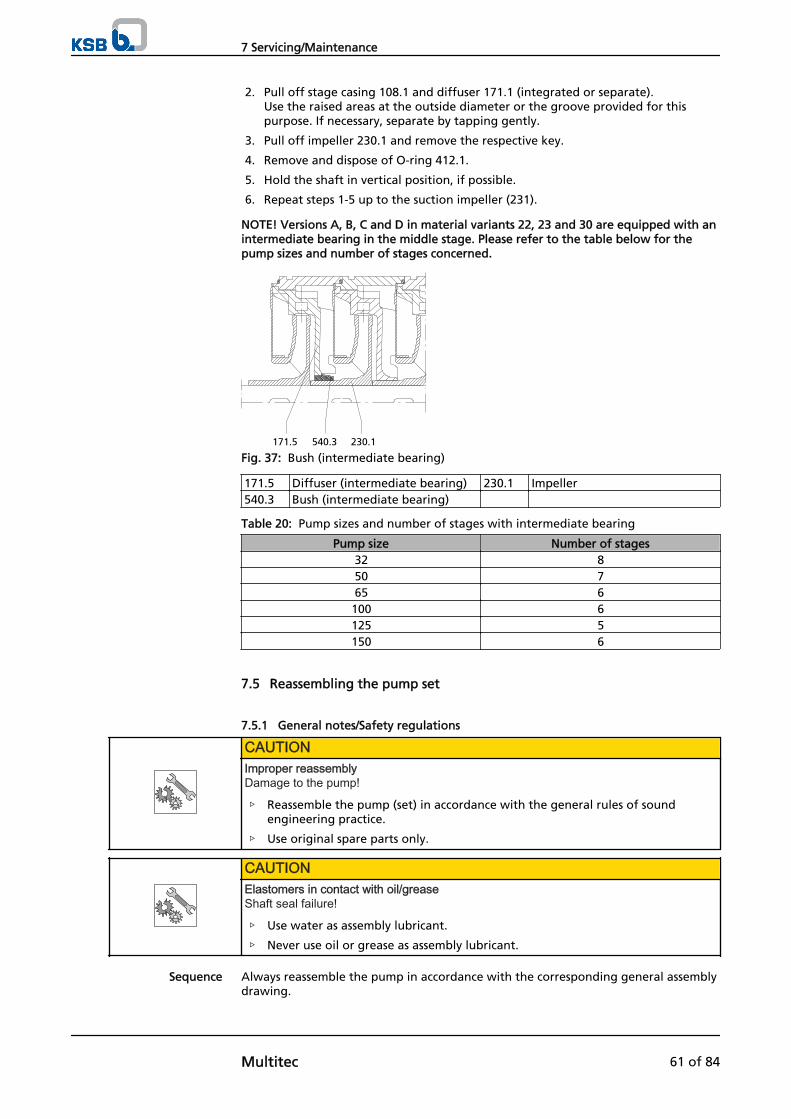
2. Pull off stage casing 108.1 and diffuser 171.1 (integrated or separate).Use the raised areas at the outside diameter or the groove provided for thispurpose. If necessary, separate by tapping gently.
3. Pull off impeller 230.1 and remove the respective key.
4. Remove and dispose of O-ring 412.1.
5. Hold the shaft in vertical position, if possible.
6. Repeat steps 1-5 up to the suction impeller (231).
NOTE! Versions A, B, C and D in material variants 22, 23 and 30 are equipped with anintermediate bearing in the middle stage. Please refer to the table below for thepump sizes and number of stages concerned.
171.5 540.3 230.1
Fig. 37: Bush (intermediate bearing)
171.5 Diffuser (intermediate bearing) 230.1 Impeller540.3 Bush (intermediate bearing)
Table 20: Pump sizes and number of stages with intermediate bearing
Pump size Number of stages32 850 765 6100 6125 5150 6
7.5 Reassembling the pump set
7.5.1 General notes/Safety regulations
CAUTIONImproper reassemblyDamage to the pump!
▷ Reassemble the pump (set) in accordance with the general rules of soundengineering practice.
▷ Use original spare parts only.
CAUTIONElastomers in contact with oil/greaseShaft seal failure!
▷ Use water as assembly lubricant.
▷ Never use oil or grease as assembly lubricant.
Always reassemble the pump in accordance with the corresponding general assemblydrawing.
Sequence
7 Servicing/Maintenance
Multitec 61 of 84
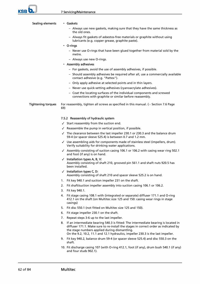
▪ Gaskets
– Always use new gaskets, making sure that they have the same thickness asthe old ones.
– Always fit gaskets of asbestos-free materials or graphite without usinglubricants (e.g. copper grease, graphite paste).
▪ O-rings
– Never use O-rings that have been glued together from material sold by themetre.
– Always use new O-rings.
▪ Assembly adhesives
– For gaskets, avoid the use of assembly adhesives, if possible.
– Should assembly adhesives be required after all, use a commercially availablecontact adhesive (e.g. "Pattex").
– Only apply adhesive at selected points and in thin layers.
– Never use quick-setting adhesives (cyanoacrylate adhesives).
– Coat the locating surfaces of the individual components and screwedconnections with graphite or similar before reassembly.
For reassembly, tighten all screws as specified in this manual. (⇨ Section 7.6 Page69)
7.5.2 Reassembly of hydraulic system
✓ Start reassembly from the suction end.
✓ Reassemble the pump in vertical position, if possible.
✓ The clearance between the last impeller 230.1 or 230.3 and the balance drum59-4 (or spacer sleeve 525.4) is between 0.7 and 1.2 mm.
✓ Use assembling aids for components made of stainless steel (impellers, drum).Verify suitability for drinking water applications.
✓ Assembly consisting of suction casing 106.1 or 106.2 with casing wear ring 502.1and foot (if any) is on hand.
✓ Installation types A, B, V: Assembly consisting of shaft 210, grooved pin 561.1 and shaft nuts 920.5 hasbeen installed.
✓ Installation types C, D:Assembly consisting of shaft 210 and spacer sleeve 525.2 is on hand.
1. Fit key 940.1 and suction impeller 231 on the shaft.
2. Fit shaft/suction impeller assembly into suction casing 106.1 or 106.2.
3. Fit key 940.1.
4. Fit stage casing 108.1 with (integrated or separate) diffuser 171.1 and O-ring412.1 on the shaft (on Multitec size 125 and 150: casing wear rings in stagecasings)
5. Fit disc 550.1 (not fitted on Multitec size 125 and 150).
6. Fit stage impeller 230.1 on the shaft.
7. Repeat steps 3-6 up to the last impeller.
8. If an intermediate bearing 540.3 is fitted: The intermediate bearing is located indiffuser 171.1. Make sure to re-install the stages in correct order as indicated bythe stage numbers applied during dismantling.On the 9.2, 10.2, 11.1 and 12.1 hydraulics, impeller 230.3 is the last impeller.
9. Fit key 940.2, balance drum 59-4 (or spacer sleeve 525.4) and disc 550.3 on theshaft.
10. Fit discharge casing 107 (with O-ring 412.1, foot (if any), drum bush 540.1 (if any)and four studs 902.1).
Sealing elements
Tightening torques
7 Servicing/Maintenance
62 of 84 Multitec
11. Insert tie bolts 905 with discs 550.4 and nuts 920.4.
12. Slightly tighten tie bolts 905.
13. Move the pump into horizontal position, setting the pump feet down on a levelsurface (e.g. workbench).
14. Tighten tie bolts 905 in two steps.First step: tighten to 50 % of specified torque; second step: tighten to 100 % ofspecified torque (⇨ Section 7.6.1 Page 69). Observe the tightening sequence given.
15. Connect balancing line 710.1 (if balance drum is fitted).
7.5.3 Installing the shaft seal
7.5.3.1 Installing the mechanical seal
For drawings and part Nos. please refer to the section "Removing the mechanicalseal".
Uni-direct ional mechanical seal
Left-hand spring
Shaft rotation: anti-clockwise
Shaft rotation: clockwise
View towards the spring-loaded ring
Right-hand spring
Fig. 39: Uni-directional spring of mechanical seal
On horizontal, long-coupled (baseplate mounted) pump sets (installation types C andD), the correct direction of rotation must be observed for mechanical seals with uni-directional springs.
Instal l ing the mechanical seal
LD
Ø
Fig. 40: Adjusting dimension L for mechanical seal
Table 21: Adjusting dimension L for mechanical seal, seal codes 55, 62, 63, 67, 68
Size Seal code Diameter DMechanical seal
[mm]
Adjusting dimensionL
[mm]55 62 63 67 68
32-50 H12N H12N H17GN H17GN -- 35 1865 H12N H12N H17GN H17GN -- 40 26100 H12N H12N H17GN H17GN H177GN 50 28125 H12N H12N H17GN H17GN H177GN 60 37,5150 H7N -- H7N H7N H7N
70 70,5
Table 22: Adjusting dimension L for mechanical seal, seal codes 42, 43, 45, 64, 81
Size Seal code Diameter DMechanical seal
[mm]
Adjusting dimensionL
[mm]42 43 45 64 81
32-50 57B 57B 57B H7N H7N 35 3165 57B 57B 57B H7N H7N 40 43,5
1
2
3
4
Fig. 38: Tie boltstightening sequence
7 Servicing/Maintenance
Multitec 63 of 84
Size Seal code Diameter DMechanical seal
[mm]
Adjusting dimensionL
[mm]42 43 45 64 81
100 57B 57B 57B H7N H7N 50 51,5125 57B 57B 57B H7N H7N 60 58150 57B 57B 57B H7N H7N 70 70,5
NOTEMechanical seals with other seal codes are installed without adjusting dimensions.
The following rules must be observed when installing the mechanical seal:
▪ For installing the mechanical seal, proceed as shown in the seal installationdrawing.
▪ Work cleanly and accurately.
▪ Only remove the protective wrapping of the contact faces immediately beforeinstallation takes place.
▪ Prevent any damage to the sealing surfaces or O-rings.
▪ After inserting the seat ring, check that it is plane-parallel in relation to thecasing part.
▪ The surface of the shaft protecting sleeve must be absolutely clean and smooth,and the sleeve's mounting edge must be chamfered.
▪ When sliding the rotating unit onto the shaft protecting sleeve, take appropriatesteps to protect the surface of the shaft protecting sleeve from damage.
✓ The notes and steps stated in (⇨ Section 7.5.1 Page 61) to (⇨ Section 7.5.2 Page62) have been observed/carried out.
✓ The bearing assembly and the individual parts of the mechanical seal are kept ina clean and level assembly area.
✓ All disassembled parts have been cleaned and checked for wear.
✓ Any damaged or worn parts have been replaced by original spare parts.
✓ The sealing surfaces have been cleaned.
1. Depending on the mechanical seal design, proceed as follows:
Instal l ing a standard mechanical seal
1. Fit O-ring 412.4 on the shaft.
2. Fit seal housing 441.1 with O-ring 412.5 and two studs 902.2 on the shaft.
3. Fit the rotating assembly (spring-loaded ring) of mechanical seal 433.1 on shaftprotecting sleeve 523.1 (observing adjusting dimension L).
4. Slip shaft protecting sleeve 523.1 with the pre-assembled rotating assembly ofmechanical seal 433.1, or shaft sleeve 523.2 with the rotating assembly ofmechanical seal 433.2 (as per seal code) onto the shaft.
5. Fit key 940.2.
6. Carefully press the stationary seat ring of mechanical seal 433.1 or 433.2 into sealcover 471.1.
7. Fit seal cover 471.1 with gasket 400.1.
8. Insert nuts 920.3 and tighten.
9. Connect circulation line 710.2 (depending on seal code).
Instal l ing an air -cooled mechanical seal ( seal code 64)
The pump may only be coupled to a motor with enclosure IP 55.
1. Fit spacer sleeve 525.8 and O-ring 412.4 on the shaft.
2. Fit seal housing 441.4 with O-ring 412.5 and heat barrier 152 on the shaft.
3. Fit the rotating assembly (spring-loaded ring) of mechanical seal 433.7 onto shaftprotecting sleeve 523.1 (observing adjusting dimension L).
7 Servicing/Maintenance
64 of 84 Multitec
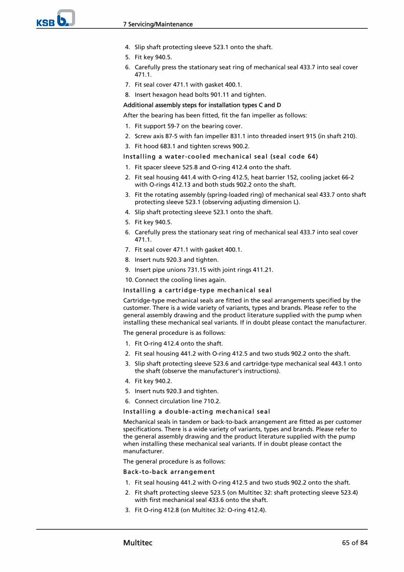
4. Slip shaft protecting sleeve 523.1 onto the shaft.
5. Fit key 940.5.
6. Carefully press the stationary seat ring of mechanical seal 433.7 into seal cover471.1.
7. Fit seal cover 471.1 with gasket 400.1.
8. Insert hexagon head bolts 901.11 and tighten.
Additional assembly steps for installation types C and D
After the bearing has been fitted, fit the fan impeller as follows:
1. Fit support 59-7 on the bearing cover.
2. Screw axis 87-5 with fan impeller 831.1 into threaded insert 915 (in shaft 210).
3. Fit hood 683.1 and tighten screws 900.2.
Instal l ing a water-cooled mechanical seal ( seal code 64)
1. Fit spacer sleeve 525.8 and O-ring 412.4 onto the shaft.
2. Fit seal housing 441.4 with O-ring 412.5, heat barrier 152, cooling jacket 66-2with O-rings 412.13 and both studs 902.2 onto the shaft.
3. Fit the rotating assembly (spring-loaded ring) of mechanical seal 433.7 onto shaftprotecting sleeve 523.1 (observing adjusting dimension L).
4. Slip shaft protecting sleeve 523.1 onto the shaft.
5. Fit key 940.5.
6. Carefully press the stationary seat ring of mechanical seal 433.7 into seal cover471.1.
7. Fit seal cover 471.1 with gasket 400.1.
8. Insert nuts 920.3 and tighten.
9. Insert pipe unions 731.15 with joint rings 411.21.
10. Connect the cooling lines again.
Instal l ing a cartr idge-type mechanical seal
Cartridge-type mechanical seals are fitted in the seal arrangements specified by thecustomer. There is a wide variety of variants, types and brands. Please refer to thegeneral assembly drawing and the product literature supplied with the pump wheninstalling these mechanical seal variants. If in doubt please contact the manufacturer.
The general procedure is as follows:
1. Fit O-ring 412.4 onto the shaft.
2. Fit seal housing 441.2 with O-ring 412.5 and two studs 902.2 onto the shaft.
3. Slip shaft protecting sleeve 523.6 and cartridge-type mechanical seal 443.1 ontothe shaft (observe the manufacturer's instructions).
4. Fit key 940.2.
5. Insert nuts 920.3 and tighten.
6. Connect circulation line 710.2.
Instal l ing a double-act ing mechanical seal
Mechanical seals in tandem or back-to-back arrangement are fitted as per customerspecifications. There is a wide variety of variants, types and brands. Please refer tothe general assembly drawing and the product literature supplied with the pumpwhen installing these mechanical seal variants. If in doubt please contact themanufacturer.
The general procedure is as follows:
Back-to-back arrangement
1. Fit seal housing 441.2 with O-ring 412.5 and two studs 902.2 onto the shaft.
2. Fit shaft protecting sleeve 523.5 (on Multitec 32: shaft protecting sleeve 523.4)with first mechanical seal 433.6 onto the shaft.
3. Fit O-ring 412.8 (on Multitec 32: O-ring 412.4).
7 Servicing/Maintenance
Multitec 65 of 84
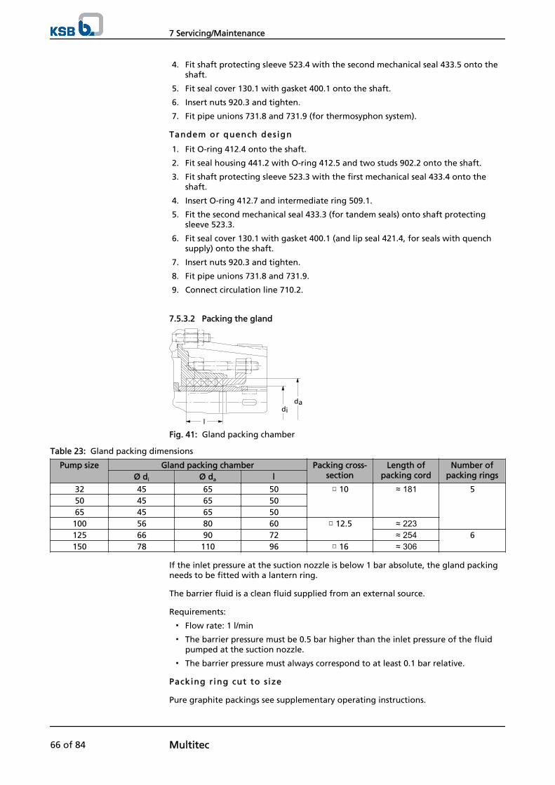
4. Fit shaft protecting sleeve 523.4 with the second mechanical seal 433.5 onto theshaft.
5. Fit seal cover 130.1 with gasket 400.1 onto the shaft.
6. Insert nuts 920.3 and tighten.
7. Fit pipe unions 731.8 and 731.9 (for thermosyphon system).
Tandem or quench design
1. Fit O-ring 412.4 onto the shaft.
2. Fit seal housing 441.2 with O-ring 412.5 and two studs 902.2 onto the shaft.
3. Fit shaft protecting sleeve 523.3 with the first mechanical seal 433.4 onto theshaft.
4. Insert O-ring 412.7 and intermediate ring 509.1.
5. Fit the second mechanical seal 433.3 (for tandem seals) onto shaft protectingsleeve 523.3.
6. Fit seal cover 130.1 with gasket 400.1 (and lip seal 421.4, for seals with quenchsupply) onto the shaft.
7. Insert nuts 920.3 and tighten.
8. Fit pipe unions 731.8 and 731.9.
9. Connect circulation line 710.2.
7.5.3.2 Packing the gland
l
dida
Fig. 41: Gland packing chamber
Table 23: Gland packing dimensions
Pump size Gland packing chamber Packing cross-section
Length ofpacking cord
Number ofpacking ringsØ di Ø da l
32 45 65 50 □ 10 ≈ 181 550 45 65 5065 45 65 50100 56 80 60 □ 12.5 ≈ 223125 66 90 72 ≈ 254 6150 78 110 96 □ 16 ≈ 306
If the inlet pressure at the suction nozzle is below 1 bar absolute, the gland packingneeds to be fitted with a lantern ring.
The barrier fluid is a clean fluid supplied from an external source.
Requirements:
▪ Flow rate: 1 l/min
▪ The barrier pressure must be 0.5 bar higher than the inlet pressure of the fluidpumped at the suction nozzle.
▪ The barrier pressure must always correspond to at least 0.1 bar relative.
Packing r ing cut to s ize
Pure graphite packings see supplementary operating instructions.
7 Servicing/Maintenance
66 of 84 Multitec
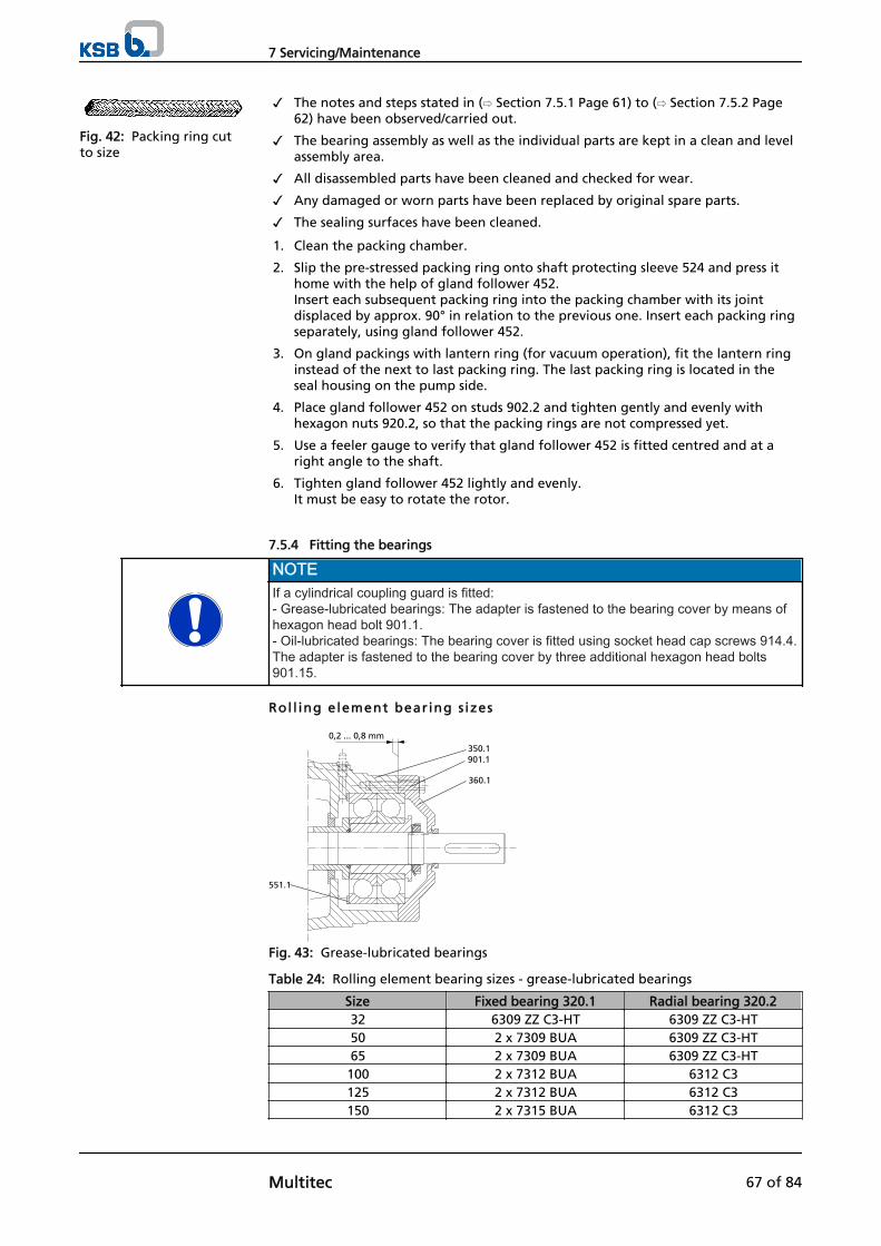
✓ The notes and steps stated in (⇨ Section 7.5.1 Page 61) to (⇨ Section 7.5.2 Page62) have been observed/carried out.
✓ The bearing assembly as well as the individual parts are kept in a clean and levelassembly area.
✓ All disassembled parts have been cleaned and checked for wear.
✓ Any damaged or worn parts have been replaced by original spare parts.
✓ The sealing surfaces have been cleaned.
1. Clean the packing chamber.
2. Slip the pre-stressed packing ring onto shaft protecting sleeve 524 and press ithome with the help of gland follower 452.Insert each subsequent packing ring into the packing chamber with its jointdisplaced by approx. 90° in relation to the previous one. Insert each packing ringseparately, using gland follower 452.
3. On gland packings with lantern ring (for vacuum operation), fit the lantern ringinstead of the next to last packing ring. The last packing ring is located in theseal housing on the pump side.
4. Place gland follower 452 on studs 902.2 and tighten gently and evenly withhexagon nuts 920.2, so that the packing rings are not compressed yet.
5. Use a feeler gauge to verify that gland follower 452 is fitted centred and at aright angle to the shaft.
6. Tighten gland follower 452 lightly and evenly.It must be easy to rotate the rotor.
7.5.4 Fitting the bearings
NOTEIf a cylindrical coupling guard is fitted:- Grease-lubricated bearings: The adapter is fastened to the bearing cover by means ofhexagon head bolt 901.1.- Oil-lubricated bearings: The bearing cover is fitted using socket head cap screws 914.4.The adapter is fastened to the bearing cover by three additional hexagon head bolts901.15.
Rol l ing element bearing s izes
0,2 ... 0,8 mm350.1901.1
360.1
551.1
Fig. 43: Grease-lubricated bearings
Table 24: Rolling element bearing sizes - grease-lubricated bearings
Size Fixed bearing 320.1 Radial bearing 320.232 6309 ZZ C3-HT 6309 ZZ C3-HT50 2 x 7309 BUA 6309 ZZ C3-HT65 2 x 7309 BUA 6309 ZZ C3-HT100 2 x 7312 BUA 6312 C3125 2 x 7312 BUA 6312 C3150 2 x 7315 BUA 6312 C3
Fig. 42: Packing ring cutto size
7 Servicing/Maintenance
Multitec 67 of 84
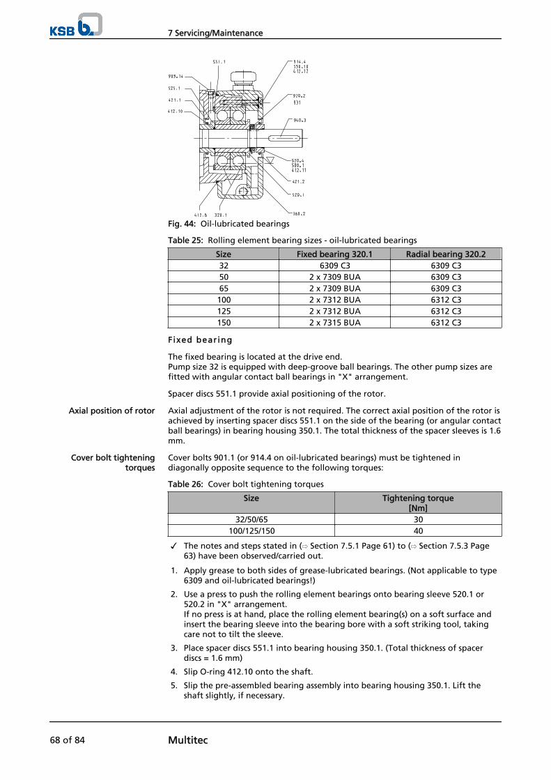
Fig. 44: Oil-lubricated bearings
Table 25: Rolling element bearing sizes - oil-lubricated bearings
Size Fixed bearing 320.1 Radial bearing 320.232 6309 C3 6309 C350 2 x 7309 BUA 6309 C365 2 x 7309 BUA 6309 C3100 2 x 7312 BUA 6312 C3125 2 x 7312 BUA 6312 C3150 2 x 7315 BUA 6312 C3
Fixed bearing
The fixed bearing is located at the drive end. Pump size 32 is equipped with deep-groove ball bearings. The other pump sizes arefitted with angular contact ball bearings in "X" arrangement.
Spacer discs 551.1 provide axial positioning of the rotor.
Axial adjustment of the rotor is not required. The correct axial position of the rotor isachieved by inserting spacer discs 551.1 on the side of the bearing (or angular contactball bearings) in bearing housing 350.1. The total thickness of the spacer sleeves is 1.6mm.
Cover bolts 901.1 (or 914.4 on oil-lubricated bearings) must be tightened indiagonally opposite sequence to the following torques:
Table 26: Cover bolt tightening torques
Size Tightening torque[Nm]
32/50/65 30100/125/150 40
✓ The notes and steps stated in (⇨ Section 7.5.1 Page 61) to (⇨ Section 7.5.3 Page63) have been observed/carried out.
1. Apply grease to both sides of grease-lubricated bearings. (Not applicable to type6309 and oil-lubricated bearings!)
2. Use a press to push the rolling element bearings onto bearing sleeve 520.1 or520.2 in "X" arrangement.If no press is at hand, place the rolling element bearing(s) on a soft surface andinsert the bearing sleeve into the bearing bore with a soft striking tool, takingcare not to tilt the sleeve.
3. Place spacer discs 551.1 into bearing housing 350.1. (Total thickness of spacerdiscs = 1.6 mm)
4. Slip O-ring 412.10 onto the shaft.
5. Slip the pre-assembled bearing assembly into bearing housing 350.1. Lift theshaft slightly, if necessary.
Axial position of rotor
Cover bolt tighteningtorques
7 Servicing/Maintenance
68 of 84 Multitec

6. Secure the rolling element bearings with shaft nuts 920.2/.6/.7.On models with two shaft nuts, firmly tighten the inner shaft nut first, thenslightly loosen it again, before locking it with the outer shaft nut.
7. Bend lockwasher 931, if any, to engage in the groove provided.
After installation of the bearings, check the following:
Grease-lubricated bearings
✓ Hexagon head bolts 901.1 have been tightened.
1. Check the clearance between cover 360.1 and bearing housing 350.1.The cover must not rest against the bearing housing.The clearance shall be between 0.2 mm and 0.8 mm.
Oil-lubricated bearings
1. Check the clearance between cover 360.2 and bearing housing 350.1.
Radial bear ing
a) b)
Fig. 45: Radial bearing: a) Deep-groove ball bearing as radial bearing - b) All otherinstallation types
Installation types C and D are equipped with a deep-groove ball bearing as radialbearing (a). On all other installation types, a silicon carbide plain bearing is fitted inthe suction casing (b).The outer race of the deep-groove ball bearing must have axial play. The bearing isinstalled without spacer discs 551.1.
Also see• General notes/Safety regulations [⇨ 61]• Installing the shaft seal [⇨ 63]
7.6 Tightening torques
7.6.1 Tie bolt tightening torques
Table 27: Tie bolt tightening torques (in Nm)
MTC material code 10-11-12-13-14 15-16-17 20-21-22-23-25-26-30-31 27-31Max. permissiblepressure
40 [bar]
63[bar]
80[bar]
32 85 95 150 -50 140 170 240 -65 250 330 430 550100 400 500 680 865125 600 1070 1370 1620150 700 1750 1500 2000 -
Final check
7 Servicing/Maintenance
Multitec 69 of 84
7.6.2 Shaft nut tightening torques
Table 28: Shaft nut tightening torques (in Nm)
Pum
p s
ize Drive end Non-drive end
A, B, C, D E,F, V A, B, E, F, V C, DNut M17) M28) M39)
10)
Nut M17) M28) M39)
10)
Nut M17) M28) M39)
10)
Nut M17) M28) M39)
10)
32 M 25x1.5 80 4011) -- M 25x1.5 80 4011) -- M 25x1.5 -- 40 100 M 25x1.5 80 40 --50 M 30x1.5 80 4011) -- M 25x1.5 80 4011) -- M 30x1.5 -- 40 120 M 30x1.5 80 40 --65 M 35x1.5 100 5011) -- M.30x1.5 80 4011) -- M 35x1.5 -- 50 150 M 35x1.5 100 50 --
100 M 42x1.5(2x)
150 50 150 M 42x1.5(2x)
150 50 150 M 42x1.5 -- 50 150 M 42x1.5 150 5011) --
125 M 52x1.5(2x)
200 60 200 M 52x1.5(2x)
200 60 200 M 50x1.5 -- 60 200 M 52x1.5 200 6011) --
150 M 62x1.5(2x)
250 80 250 M 62x1.5(2x)
250 80 250 M 60x1.5 -- 80 250 M 62x1.5(2x)
250 80 250
Procedure for t ightening the shaft nuts with a torque wrench
Nut with lockwasher - (drive end and non-drive end on installation types C and D)
1. Tighten nut to torque M1, then loosen again.
2. Tighten to torque M2 and bend lockwasher.
Nut with locknut - drive end (and non-drive end on installation types C and D)
1. Tighten first nut to torque M1, then loosen again.
2. Tighten first nut to tightening torque M2.
3. Tighten locknut to torque M3 while blocking the first nut.
Nut with locknut - non-drive end (except installation types C and D)
1. Tighten first nut with tightening torque M1.
2. Tighten locknut to torque M2 while blocking the first nut.
Procedure for t ightening the shaft nut without a torque wrench
If there is no suitable torque wrench available for tightening the shaft nuts, proceedas follows, depending on the pump version:
Nut with lockwasher - drive end (or non-drive end on installation types C and D)
1. Tighten the shaft nut firmly.
2. Loosen the shaft nut again.
3. Tighten the shaft nut moderately.
4. Bend lockwasher.
Nut with locknut - drive end (or non-drive end on installation types C and D)
1. Tighten the first shaft nut firmly.
2. Loosen the first shaft nut again.
3. Tighten the first shaft nut moderately.
4. Tighten the locknut firmly against the first shaft nut while blocking the first nut.
Nut with locknut - non-drive end (except installation types C and D)
1. Tighten the first shaft nut moderately.
2. Tighten the locknut firmly against the first shaft nut while blocking the first nut.
7) Loosen again after first tightening8) Final tightening torque of first nut9) Tightening torque of second nut (if any)10) Block first nut when tightening11) Bend lockwasher
7 Servicing/Maintenance
70 of 84 Multitec
7.7 Spare parts stock
7.7.1 Ordering spare parts
Always quote the following data when ordering replacement or spare parts:
▪ Type series
▪ Material variant
▪ Size
▪ Seal code
▪ KSB order number
▪ Order item number
▪ Consecutive number
▪ Year of construction
Refer to the name plate for all data. (⇨ Section 4.3 Page 16)
Also supply the following data:
▪ Description
▪ Part No.
▪ Quantity of spare parts
▪ Delivery address
▪ Mode of dispatch (freight, mail, express freight, air freight)
Refer to the exploded view or general assembly drawing for part numbers anddescriptions. (⇨ Section 9.1 Page 75)
7.7.2 Recommended spare parts stock for 2 years' operation to DIN 24296
NOTEWe recommend to replace various wear parts such as rolling element bearings, sealingelements, circlips, etc. (see spare parts list below) whenever the hydraulic system hasbeen completely dismantled.
Table 29: Quantity of spare parts for recommended spare parts stock
Part No. Description Number of pumps (including stand-by pumps)
2 3 4 5 6 and 7 8 and 9 10 andmore
For grease-lubricated pump sets210 Shaft (complete with small parts) 1 1 2 2 2 3 30 %230 Impeller (set) 1 1 1 2 2 3 30 %231 Suction impeller 1 1 1 2 2 3 30 %412.1 O-ring (set) 4 8 8 8 9 12 150 %433 Mechanical seal (complete) 2 3 4 5 6 7 90 %46112) Gland packing (set) 4 6 8 8 9 12 150 %
50213) Casing wear ring (set) 2 2 2 3 3 4 50 %523 Shaft sleeve 2 2 2 3 3 4 50 %52412) Shaft protecting sleeve 2 2 2 3 3 4 50 %525 Spacer sleeve 2 2 2 3 3 4 50 %550.114) Disc (set) 2 2 2 3 3 4 50 %
12) For seal codes 65 and 66 (gland packing); parts No. 433 and 523 not fitted13) On pump sizes 125 and 150 only; on pump sizes 32 to 100 with material codes 20 to 3014) On pump sizes 32 to 100 only
7 Servicing/Maintenance
Multitec 71 of 84
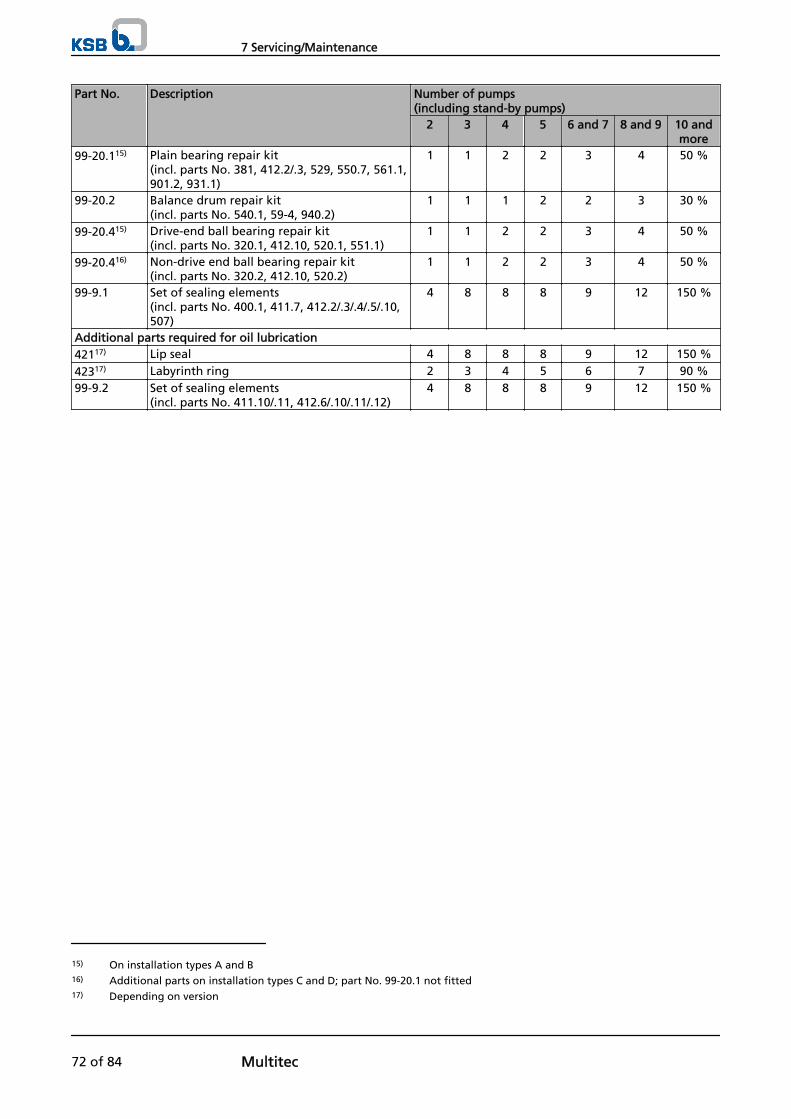
Part No. Description Number of pumps (including stand-by pumps)
2 3 4 5 6 and 7 8 and 9 10 andmore
99-20.115) Plain bearing repair kit (incl. parts No. 381, 412.2/.3, 529, 550.7, 561.1,901.2, 931.1)
1 1 2 2 3 4 50 %
99-20.2 Balance drum repair kit(incl. parts No. 540.1, 59-4, 940.2)
1 1 1 2 2 3 30 %
99-20.415) Drive-end ball bearing repair kit (incl. parts No. 320.1, 412.10, 520.1, 551.1)
1 1 2 2 3 4 50 %
99-20.416) Non-drive end ball bearing repair kit(incl. parts No. 320.2, 412.10, 520.2)
1 1 2 2 3 4 50 %
99-9.1 Set of sealing elements(incl. parts No. 400.1, 411.7, 412.2/.3/.4/.5/.10,507)
4 8 8 8 9 12 150 %
Additional parts required for oil lubrication42117) Lip seal 4 8 8 8 9 12 150 %
42317) Labyrinth ring 2 3 4 5 6 7 90 %99-9.2 Set of sealing elements
(incl. parts No. 411.10/.11, 412.6/.10/.11/.12)4 8 8 8 9 12 150 %
15) On installation types A and B16) Additional parts on installation types C and D; part No. 99-20.1 not fitted17) Depending on version
7 Servicing/Maintenance
72 of 84 Multitec
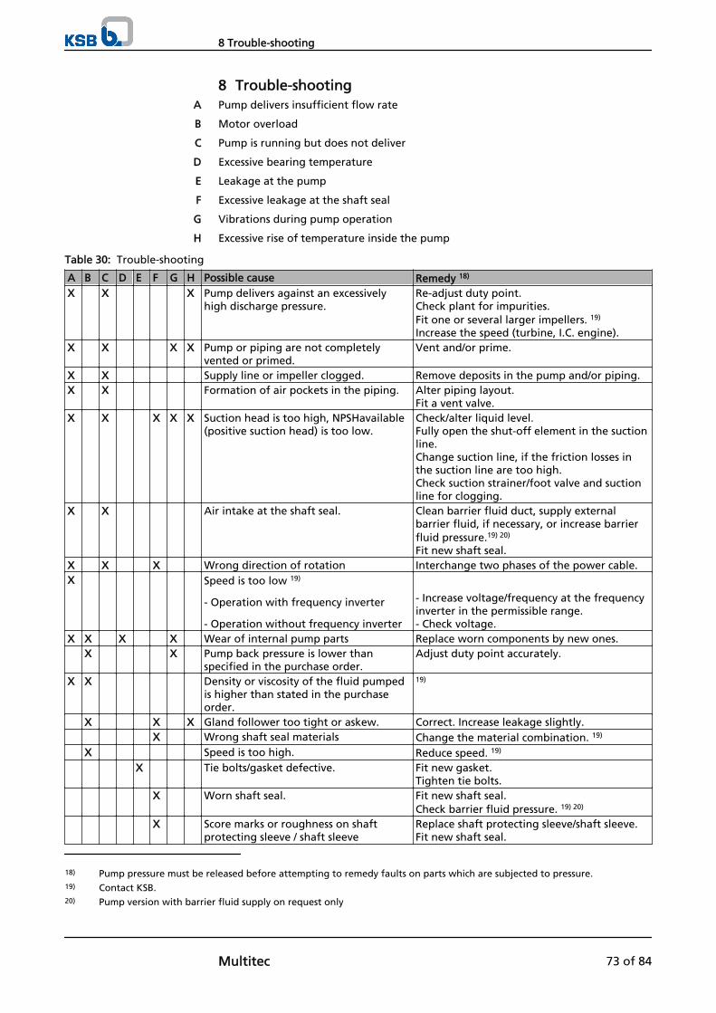
8 Trouble-shootingPump delivers insufficient flow rate
Motor overload
Pump is running but does not deliver
Excessive bearing temperature
Leakage at the pump
Excessive leakage at the shaft seal
Vibrations during pump operation
Excessive rise of temperature inside the pump
Table 30: Trouble-shooting
A B C D E F G H Possible cause Remedy 18)
X X X Pump delivers against an excessivelyhigh discharge pressure.
Re-adjust duty point.Check plant for impurities.Fit one or several larger impellers. 19)
Increase the speed (turbine, I.C. engine).X X X X Pump or piping are not completely
vented or primed.Vent and/or prime.
X X Supply line or impeller clogged. Remove deposits in the pump and/or piping.X X Formation of air pockets in the piping. Alter piping layout.
Fit a vent valve.X X X X X Suction head is too high, NPSHavailable
(positive suction head) is too low.Check/alter liquid level.Fully open the shut-off element in the suctionline.Change suction line, if the friction losses inthe suction line are too high.Check suction strainer/foot valve and suctionline for clogging.
X X Air intake at the shaft seal. Clean barrier fluid duct, supply externalbarrier fluid, if necessary, or increase barrierfluid pressure.19) 20)
Fit new shaft seal.X X X Wrong direction of rotation Interchange two phases of the power cable.X Speed is too low 19)
- Operation with frequency inverter
- Operation without frequency inverter
- Increase voltage/frequency at the frequencyinverter in the permissible range.- Check voltage.
X X X X Wear of internal pump parts Replace worn components by new ones. X X Pump back pressure is lower than
specified in the purchase order.Adjust duty point accurately.
X X Density or viscosity of the fluid pumpedis higher than stated in the purchaseorder.
19)
X X X Gland follower too tight or askew. Correct. Increase leakage slightly. X Wrong shaft seal materials Change the material combination. 19)
X Speed is too high. Reduce speed. 19)
X Tie bolts/gasket defective. Fit new gasket.Tighten tie bolts.
X Worn shaft seal. Fit new shaft seal.Check barrier fluid pressure. 19) 20)
X Score marks or roughness on shaftprotecting sleeve / shaft sleeve
Replace shaft protecting sleeve/shaft sleeve.Fit new shaft seal.
A
B
C
D
E
F
G
H
18) Pump pressure must be released before attempting to remedy faults on parts which are subjected to pressure.19) Contact KSB.20) Pump version with barrier fluid supply on request only
8 Trouble-shooting
Multitec 73 of 84
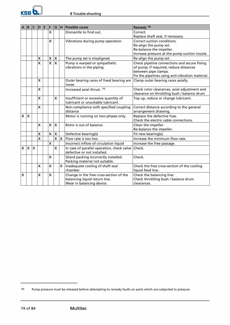
A B C D E F G H Possible cause Remedy 18)
X Dismantle to find out. Correct.Replace shaft seal, if necessary.
X Vibrations during pump operation Correct suction conditions.Re-align the pump set.Re-balance the impeller.Increase pressure at the pump suction nozzle.
X X X The pump set is misaligned. Re-align the pump set. X X X Pump is warped or sympathetic
vibrations in the piping.Check pipeline connections and secure fixingof pump; if required, reduce distancesbetween pipe clamps.Fix the pipelines using anti-vibration material.
X Outer bearing races of fixed bearing areloose.
Clamp outer bearing races axially.
X Increased axial thrust. 19) Check rotor clearances, axial adjustment andclearance on throttling bush / balance drum.
X X Insufficient or excessive quantity oflubricant or unsuitable lubricant.
Top up, reduce or change lubricant.
X Non-compliance with specified couplingdistance
Correct distance according to the generalarrangement drawing.
X X Motor is running on two phases only. Replace the defective fuse.Check the electric cable connections.
X X X Rotor is out of balance. Clean the impeller.Re-balance the impeller.
X X X Defective bearing(s) Fit new bearing(s). X X X Flow rate is too low. Increase the minimum flow rate. X Incorrect inflow of circulation liquid Increase the free passage.X X X X In case of parallel operation, check valve
defective or not installed.Check.
X Gland packing incorrectly installed.Packing material not suitable.
Check.
X X X Inadequate cooling of shaft sealchamber
Check the free cross-section of the coolingliquid feed line.
X X X Change in the free cross-section of thebalancing liquid return line.Wear in balancing device.
Check the balancing line.Check throttling bush / balance drumclearances.
18) Pump pressure must be released before attempting to remedy faults on parts which are subjected to pressure.
8 Trouble-shooting
74 of 84 Multitec
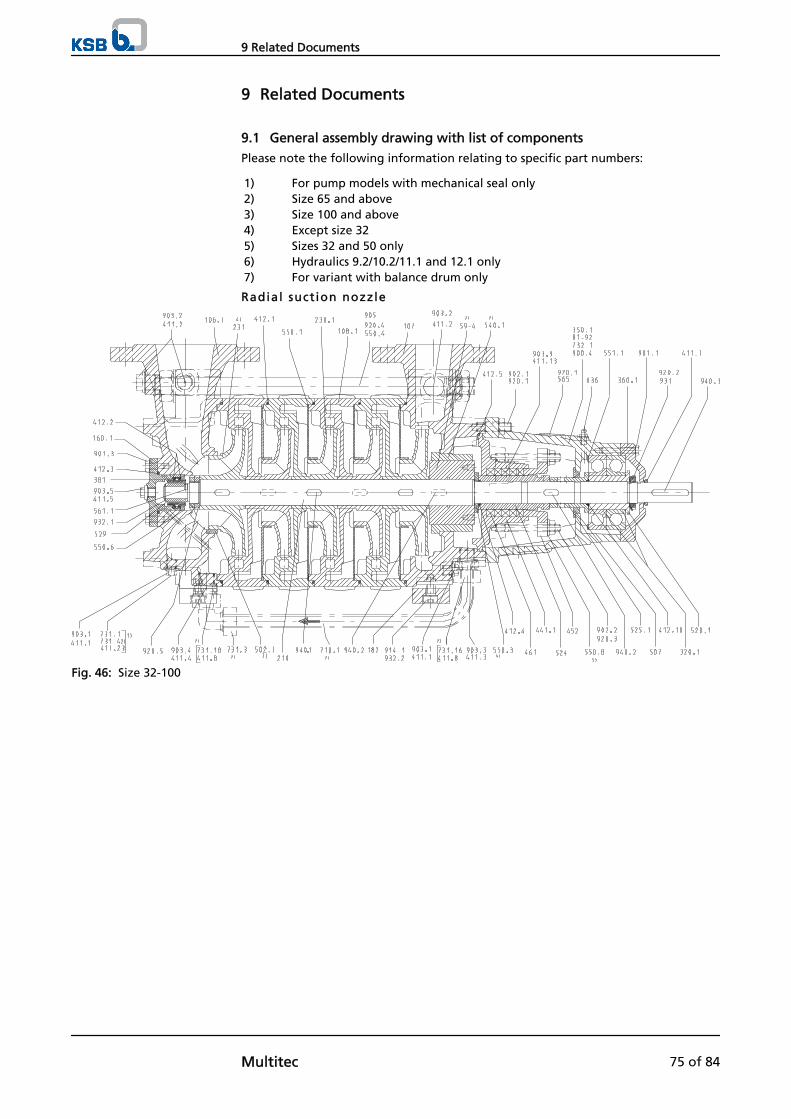
9 Related Documents
9.1 General assembly drawing with list of components
Please note the following information relating to specific part numbers:
1) For pump models with mechanical seal only2) Size 65 and above3) Size 100 and above4) Except size 325) Sizes 32 and 50 only6) Hydraulics 9.2/10.2/11.1 and 12.1 only7) For variant with balance drum only
Radial suct ion nozzle
Fig. 46: Size 32-100
9 Related Documents
Multitec 75 of 84
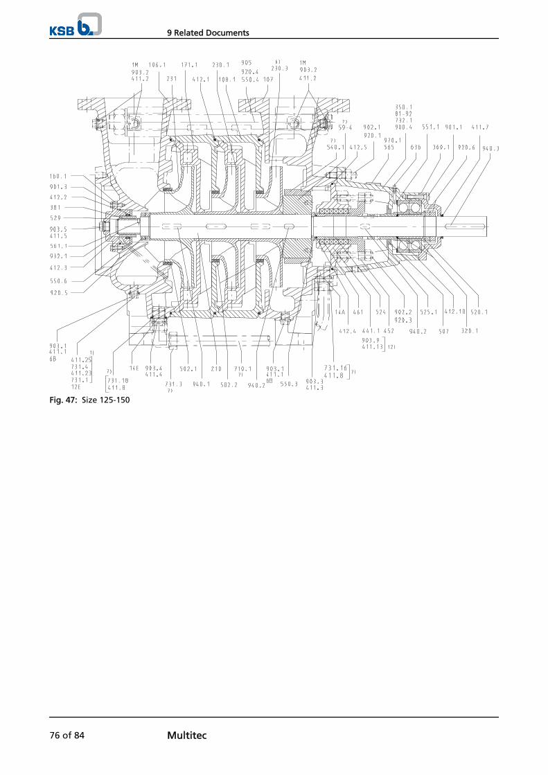
Fig. 47: Size 125-150
9 Related Documents
76 of 84 Multitec
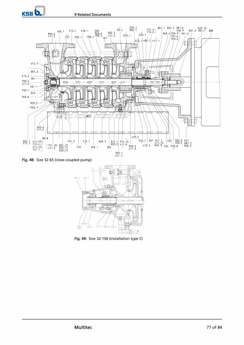
Fig. 48: Size 32-65 (close-coupled pump)
Fig. 49: Size 32-150 (installation type C)
9 Related Documents
Multitec 77 of 84
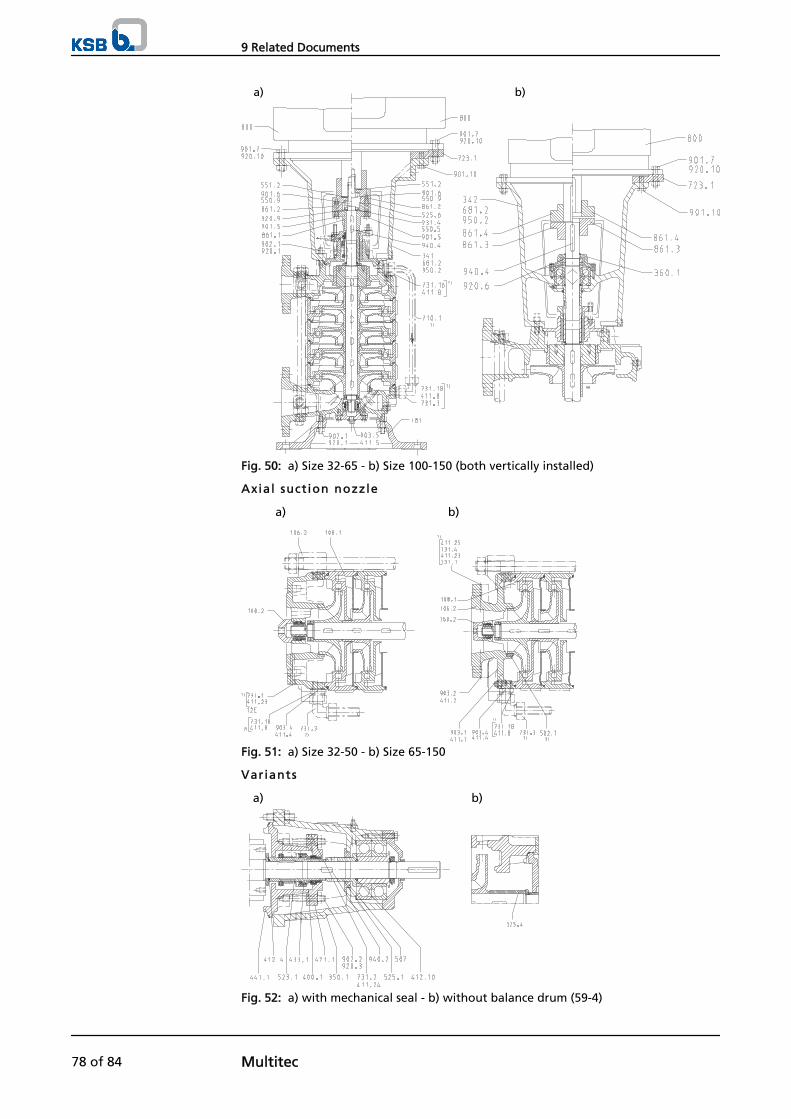
a) b)
Fig. 50: a) Size 32-65 - b) Size 100-150 (both vertically installed)
Axial suct ion nozzle
a) b)
Fig. 51: a) Size 32-50 - b) Size 65-150
Variants
a) b)
Fig. 52: a) with mechanical seal - b) without balance drum (59-4)
9 Related Documents
78 of 84 Multitec
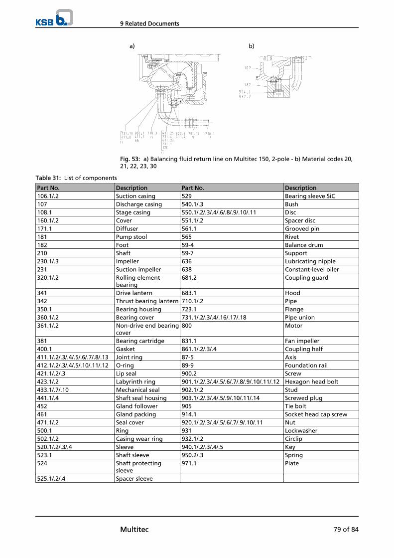
a) b)
Fig. 53: a) Balancing fluid return line on Multitec 150, 2-pole - b) Material codes 20,21, 22, 23, 30
Table 31: List of components
Part No. Description Part No. Description106.1/.2 Suction casing 529 Bearing sleeve SiC107 Discharge casing 540.1/.3 Bush108.1 Stage casing 550.1/.2/.3/.4/.6/.8/.9/.10/.11 Disc160.1/.2 Cover 551.1/.2 Spacer disc171.1 Diffuser 561.1 Grooved pin181 Pump stool 565 Rivet182 Foot 59-4 Balance drum210 Shaft 59-7 Support230.1/.3 Impeller 636 Lubricating nipple231 Suction impeller 638 Constant-level oiler320.1/.2 Rolling element
bearing681.2 Coupling guard
341 Drive lantern 683.1 Hood342 Thrust bearing lantern 710.1/.2 Pipe350.1 Bearing housing 723.1 Flange360.1/.2 Bearing cover 731.1/.2/.3/.4/.16/.17/.18 Pipe union361.1/.2 Non-drive end bearing
cover800 Motor
381 Bearing cartridge 831.1 Fan impeller400.1 Gasket 861.1/.2/.3/.4 Coupling half411.1/.2/.3/.4/.5/.6/.7/.8/.13 Joint ring 87-5 Axis412.1/.2/.3/.4/.5/.10/.11/.12 O-ring 89-9 Foundation rail421.1/.2/.3 Lip seal 900.2 Screw423.1/.2 Labyrinth ring 901.1/.2/.3/.4/.5/.6/.7/.8/.9/.10/.11/.12 Hexagon head bolt433.1/.7/.10 Mechanical seal 902.1/.2 Stud441.1/.4 Shaft seal housing 903.1/.2/.3/.4/.5/.9/.10/.11/.14 Screwed plug452 Gland follower 905 Tie bolt461 Gland packing 914.1 Socket head cap screw471.1/.2 Seal cover 920.1/.2/.3/.4/.5/.6/.7/.9/.10/.11 Nut500.1 Ring 931 Lockwasher502.1/.2 Casing wear ring 932.1/.2 Circlip520.1/.2/.3/.4 Sleeve 940.1/.2/.3/.4/.5 Key523.1 Shaft sleeve 950.2/.3 Spring524 Shaft protecting
sleeve971.1 Plate
525.1/.2/.4 Spacer sleeve
9 Related Documents
Multitec 79 of 84
10 EC Declaration of Conformity
Manufacturer: KSB S.A.S.Allée de Sagan
36004 Chateauroux
The manufacturer herewith declares that the pump/pump set:
Multitec, Multitec-RO
KSB order number: ...................................................................................................
KSB order item number: .......................................................................
▪ is in conformity with the provisions of the following directives as applicable in their current version:
– EC Machinery Directive 2006/42/EC
The manufacturer also declares that
▪ the following harmonised international standards were applied:
– ISO 12100-1/A1, ISO 12100-2/A1,
– ISO 14121-1,
– EN 809/A1
Châteauroux, 29.12.2009
...........................................................
Name
Function
Responsible for compiling the technical documentationKSB S.A.S.
Allée de Sagan
36004 Châteauroux
10 EC Declaration of Conformity
80 of 84 Multitec
11 Certificate of Decontamination
Type ................................................................................................................................Order number/Order item number21) ................................................................................................................................ Delivery date ................................................................................................................................ Field of application: ................................................................................................................................ Fluid handled21) : ................................................................................................................................
Please tick where applicable21) :
⃞ ⃞ ⃞ ⃞radioactive explosive corrosive toxic
⃞ ⃞ ⃞ ⃞harmful bio-hazardous highly flammable safe
Reason for return21) : ................................................................................................................................ Comments: ................................................................................................................................ ................................................................................................................................ The pump/accessories have been carefully drained, cleaned and decontaminated inside and outside prior to dispatch/placingat your disposal.
On sealless pumps, the rotor has been removed from the pump for cleaning.
⃞ No special safety precautions are required for further handling.⃞ The following safety precautions are required for flushing fluids, fluid residues and disposal:
............................................................................................................................................................... ............................................................................................................................................................... We confirm that the above data and information are correct and complete and that dispatch is effected in accordance withthe relevant legal provisions.
.................................................................... ....................................................... .......................................................Place, date and signature Address Company stamp
21) Required fields
11 Certificate of Decontamination
Multitec 81 of 84
Index
AAbrasive fluids 40
BBearing temperature 43, 44Bearings 16
CCertificate of decontamination 81Clearance gaps 44Commissioning/start-up 32Configuration 17Constant level oiler 33Coupling 44Coupling alignment 25
DDesign 16Designation 15Direction of rotation 30Dismantling 49Disposal 14
EExplosion protection 10, 17, 19, 20, 25, 27, 28, 29, 30,34, 36, 38, 42, 43, 44, 45
FFilter 22, 45Final check 35Frequency of starts 38, 39Function 17
GGeneral assembly drawing 75Gland packing 37Grease lubrication
Grease quality 47Intervals 47
IImpeller type 16Installation
Installation on foundation 21Installation at site 20Intended use 8
MMaintenance/ repair 42Mechanical seal 37Misuse 9Monitoring equipment 12
NName plate 16Noise characteristics 18
OOil lubrication
Intervals 46Oil quality 46
Operating limits 8, 38Order number 6Ordering spare parts 71Other applicable documents 6
PPartly completed machinery 6Permissible forces at the pump nozzles 24Piping 22Preservation 40Priming and venting 34Product description 15Pump casing 16
RReassembly 49, 61Return to supplier 14Returning to service 41Running noises 43
SSafety 8Safety awareness 9Scope of supply 18Shaft seal 16Shutdown 40Spare parts stock 71Start-up 36Storage 40
TTemperature limits 11Tightening torques 70Trouble-shooting 73
Index
82 of 84 Multitec


KSB AktiengesellschaftP.O. Box 1361 • 91253 Pegnitz • Bahnhofplatz 1, 91257 Pegnitz (Germany) Tel. +49 9241 71-0 • Fax +49 9241 71-1793www.ksb.com
1777
.8/1
0-10

![VENTS KSB EC - folheto187 VENTS. Industrial and commercial ventilation 02201 Point Power [W] KSB 100 EC KSB 125 EC KSB 150 EC KSB 160 EC KSB 200 EC KSB 250 EC KSB 315 EC 1 83 83 83](https://img.dokumen.tips/doc/110x75/5e921ded45cff356a6235202/vents-ksb-ec-folheto-187-vents-industrial-and-commercial-ventilation-02201-point.jpg)


![[TR] Invikta WTD [TR] Invikta WTD - URSAN Pompa](https://img.dokumen.tips/doc/110x75/62349ad01ddc377a5c6869f4/tr-invikta-wtd-tr-invikta-wtd-ursan-pompa.jpg)