Embed Size (px)
Citation preview

Owner's Manual/Manual Del Propietario
I RR RN I1/2 HP
315Mx= GARAGE DOOR OPENERABRIDOR DE PUERTA DE COCHERA 315MxzFor Residential Use Only/Solo para uso residencial
Model/Modelo 139.53910D
II'1
G3
m
"0
Z_C3
Read and follow all safety rulesand operating instructions beforefirst use of this product.
Fasten the manual near the garagedoor after installation.
Periodic checks of the opener arerequired to ensure safe operation.
Leer y seguir todas las reglas deseguridad y las instrucciones deoperacion antes de usar esteproducto por primera vez.
Guardar este manual cerca de lapuerta de la cochera.
Se deben realizar revisionesperiodicas del abridor de puertaspara asegurar su operacionsegura.
Sears, Roebuck and Co., Hoffman Estates, IL 60179 U.S.Awww.sears.com/craftsman
Downloaded from www.Manualslib.com manuals search engine

TABLE OF CONTENTS
Introduction 2- 7
Safety symbol and signal word review ........................ 2
Preparing your garage door ........................................ 3Tools needed ............................................................... 3
Planning .................................................................. 4-5
Carton inventory .......................................................... 6
Hardware inventory ..................................................... 7
Assembly 8.11
Assemble the rail and install the trolley ...................... 8Fasten the rail to the motor unit andinstall the idler pulley ................................................... 9Install the chain/cable ................................................ 10
Tighten the chain ....................................................... 11
Installation 11-26
Installation safety instructions .................................... 11Determine the header bracket location ..................... 12
Install the header bracket .......................................... 13
Attach the rail to the header bracket ......................... 14
Position the opener ................................................... 15
Hang the opener ....................................................... 16Install the door control ............................................... 17
Install the light ........................................................... 18
Attach the emergency release rope and handle ....... 18
Electrical requirements .............................................. 19
Install The Protector System 'R;.............................. 20-22Fasten the door bracket ....................................... 23-24
Connect the door arm to the trolley ..................... 25-26
Adjustment 27-29
Adjust the travel limits ............................................... 27
Adjust the force ......................................................... 28
Test the safety reversal system ................................. 29
Test The Protector System _:...................................... 29
Operation 30-34
Operation safety instructions ..................................... 30
Using your garage door opener ................................ 30
Using the wall-mounted Door Control ....................... 31
To open the door manually ........................................ 31
Care of your garage door opener .............................. 32
Having a problem? .................................................... 33
Diagnostic chart ......................................................... 34
Programming 35-36
To add or reprogram a hand-held remote control .....35To erase all codes ..................................................... 35
&Function Remotes .................................................. 35
To add, reprogram or changea Keyless Entry PIN .................................................. 36
Repair Parts 37.38
Rail assembly parts ................................................... 37
Installation parts ........................................................ 37
Motor unit assembly parts ......................................... 38
Accessories 39
Warranty 39
Repair Parts & Service Backcover
INTRODUCTION
Safety Symboland Signal Word Review
This garage door opener has been designed and tested to offer safe service provided it is installed, operated,maintained and tested in strict accordance with the instructions and warnings contained in this manual.
Mechanical
Electrical
When you see these Safety Symbols and SignalWords on the following pages, they will alert you tothe possibility of serious injury or death if you donot comply with the warnings that accompany them.The hazard may come from something mechanicalor from electric shock. Read the warnings carefully.
When you see this Signal Word on the followingpages, it will alert you to the possibility of damage toyour garage door and/or the garage door opener ifyou do not comply with the cautionary statementsthat accompany it. Read them carefully.
Downloaded from www.Manualslib.com manuals search engine

Preparing your garage door
Before you begin:• Disable locks.
• Remove any ropes connected to garage door.
• Complete the following test to make sure yourgarage door is balanced and is not sticking orbinding:
1. Lift the door about halfway as shown. Releasethe door. If balanced, it should stay in place,supported entirely by its springs.
2. Raise and lower the door to see if there is anybinding or sticking.
If your door binds, sticks, or is out of balance, call atrained door systems technician.
To prevent possible SERIOUSINJURYor DEATH:• ALWAYScall a trained door systems technician if
garage door binds, sticks, or is out of balance.Anunbalancedgarage door may not reverse whenrequired.
• NEVERtry to loosen, move or adjust garage door, doorsprings, cables, pulleys, brackets or their hardware,allof which are under EXTREMEtension.
• Disable ALL locks and removeALL ropes connected togarage door BEFOREinstalling and operating garagedoor opener to avoid entanglement.
To prevent damageto garage door and opener:• ALWAYSdisable locks BEFOREinstalling and operating
the opener.• ONLYoperate garagedoor opener at 120V,60 Hzto
avoid malfunction and damage.
Sectional Door
One-Piece Door Tools needed
During assembly, installation and adjustment of theopener, instructions will call for hand tools asillustrated below.
Stepladder
Level (optional)
Drill
Tape Measure
3/16", 5/16"and 5/32"
and 1/4"
Pencil
Wire Cutters
Hack Saw
Screwdriver
Adjustable End Wrench
Downloaded from www.Manualslib.com manuals search engine

Planning
Identify the type and height of your garage door.Survey your garage area to see if any of theconditions below apply to your installation. Additionalmaterials may be required. You may find it helpful torefer back to this page and the accompanyingillustrations as you proceed with the installation ofyour opener.
Depending on your requirements, there are severalinstallation steps which may call for materials orhardware not included in the carton.
• Installation Step 1 - Look at the wall or ceilingabove the garage door. The header bracket mustbe securely fastened to structural supports.
• Installation Step 5 - Do you have a finished ceilingin your garage? If so, a support bracket andadditional fastening hardware may be required.
• Installation Step 10- Depending upon garageconstruction, extension brackets or wood blocksmay be needed to install sensors.
• Installation Step 10 -Alternate floor mounting ofthe safety reversing sensor will require hardwarenot provided.
Do you have an access door in addition to thegarage door? If not, Model 53702 Emergency KeyRelease is required. See Accessories page.
Look at the garage door where it meets the floor.Any gap between the floor and the bottom of thedoor must not exceed 1/4" (6 mm). Otherwise, thesafety reversal system may not work properly. SeeAdjustment Step 3. Floor or door should berepaired.
SECTIONAL DOOR INSTALLATIONS
• Do you have a steel, aluminum, fiberglass or glasspanel door? If so, horizontal and verticalreinforcement is required (Installation Step 11).
• The opener should be installed above the center ofthe door. If there is a torsion spring or centerbearing plate in the way of the header bracket, itmay be installed within 4 feet (1.22 m) to the left orright of the door center. See Installation Steps 1and 11.
• If your door is more than 7 feet (2.13 m) high, seerail extension kits listed on Accessories page.
SECTIONAL DOOR INSTALLATION
Horizontal and vertical reinforcementis needed for lightweight garage doors(fiberglass, steel, aluminum, door withglass panels, etc.). See page 23 for details.
k
Header Wall
Slack in chain tensionis normal when
garage door is closed.
FINISHED CEILING
Supportfastening hardwareis required.See page 16.
OR
Torsion Spring
Motor unit
Gap between floorand bottom of door
must not exceed 1/4" (6 mm).
Wall-
DoorControl
\
" Safety ReversingSensor
Access Door
O
eaderrail
arageeor
HeaderBracket
/' Trolley,/ Stop Bolt Trolley
Garcage
Spring
__ oor
Arm
CLOSED POSITION
Chain
.......EmergencyRelease
Rope & Handle
Downloaded from www.Manualslib.com manuals search engine

Planning (Continued)
ONE-PIECE DOOR INSTALLATIONS
• Generally, a one-piece door does not requirereinforcement. If your door is lightweight, refer tothe information relating to sectional doors inInstallation Step 11.
• Depending on your door's construction, you mayneed additional mounting hardware for the doorbracket (Step 11).
Without a properly working safety reversal system,persons (particularly small children) could beSERIOUSLYINJUREDor KILLEDby a closing garagedoor.
• The gap betweenthe bottom of the garage door andthe floor MUST NOTexceed 1/4" (6 mm). Otherwise,the safety reversal system may not work properly.
• The floor or the garage door MUST be repairedtoeliminate the gap.
ONE-PIECE DOOR WITHOUT TRACK
FINtSHED CEILING
Support bracket
& fasteninghardware is required.See page t6.
Safety Reversing Sensor
Header WallRail
Slack in chain tension
is normal when garagedoor is closed
Wall-mountedDoor Control
Access E_Door
O
Safety Reversing
Gap between floor Sensor
and bottom of door must not exceed 1/4" (6 ram).
leader_all
",
Motor Unit
CLOSED POSIT|ON
Trolley Stop Bolt Cable Trolley
EmergencyReleaseRope & Handle
ONE-PIECE DOOR WITH TRACK
SafetyReversing Sensor
ol
ReversingGap between floor Sensorand bottom of doormust not exceed 1/4" (6 ram).
det
CLOSED POSIT_ON
Trolley Stop Bolt Cable Chain
__E23 i i
Header Curved _ RlailBracket Door Ar
_, ooooooooooo) j I
_""- Door I '- I Em,ergency• Release
Bracket Straight h _ele_?_?///I Door" _- ,Hope,&
7//'j/_ Garage Arm _. Handle///I Door
Downloaded from www.Manualslib.com manuals search engine

Carton Inventory
Your garage door opener is packaged in one cartonwhich contains the motor unit and all parts illustratedbelow. Accessories will depend on the modelpurchased. If anything is missing, carefully check the
packing material. Parts may be stuck in the foam.Hardware for assembly and installation is shown onthe next page. Save the carton and packing materialuntil installation and adjustment is complete.
Trolley
Door Control Button
Three-Function Remote Control
with Visor Clip (2) yChain Spreader
Idler Pulley
RailCenter/BackSections
of6_-_T6-__ n_
/
Motor Unit with Light Lens
Hanging Brackets
Door Bracket "U" Bracket
Header Bracket
2-Conductor Bell WireWhite & White/Red
Curved DoorArm Section
Safety SensorBracket (2)
(2) Safety Reversing Sensors(1 Sending Eye and 1 Receiving Eye)with 2-Conductor White &White/Black Bell Wire attached
Safety LabelsandLiterature
Straight DoorArm Section
Downloaded from www.Manualslib.com manuals search engine

Hardware Inventory
Separate all hardware and group as shown below for the assembly and installation procedures.
ASSEMBLY HARDWARE
@Lock Nut Lock Washer Nut
1/4"-20 (2) 3/8" (1) 3/8" (1)
Bolt 1/4"-20xl-3/4" (2)
Trolley Threaded Shaft (1)
i
Master
Link (2) Idler Bolt (1)
INSTALLATION HARDWARE
Carriage Bolt1/4"-20xl/2" (2)
Wing Nut1/4"-20 (2)
Lag Screw5/16"-9xl-5/8" (2)
Lag Screw5/16"-18xl -7/8" (2)
Carriage Bolt5/16"-18x2-1/2" (2)
Clevis Pin
5/16"x1-1/2" (1)
RingFastener (3)
Hex Bolt
5/16"-18x7/8" (4)
Screw
6ABx1-1/4" (2)
Drywall Anchors (2)
8} olClevis Pin
5/16"x1" (1)
Nut 5/16"-18 (8)
©Lock Washer 5/16" (7)
Handle
Insulated
Staples (30)
Screw 6-32xl" (2)
Spacer(2)
Clevis Pin5/16"x1-1/4" (1)
Rope
Downloaded from www.Manualslib.com manuals search engine

ASSEMBLY STEP 1
Assemble the Rail & Install the Trolley
To avoid installation difficulties, do not run thegarage door opener until instructed to do so.
The front rail has a cut out "window" at the door end(see illustration). The hole above this window islarger on the top of the rail than on the bottom. Asmaller hole 3-1/2" (8.9 cm) away is close to the railedge. Rotate the back rail so it has a similar holeclose to the opposite edge, about 4-3/4" (12 cm)from the far end.
1. Remove the straight door arm and hangingbracket packaged inside the front rail and setaside for Installation Step 5 and 12. NOTE: Toprevent INJURY while unpacking the rail carefullyremove the straight door arm stored within the railsection.
2. Align the rail sections on a flat surface as shownand slide the tapered ends into the larger ones.Tabs along the side will lock into place.
To prevent INJURYfrom pinching, keep hands andfingers awayfrom the joints while assembling the rail.
3. Place the motor unit on packing material to protectthe cover, and rest the back end of the rail on top.For convenience, put a support under the frontend of the rail.
4. As a temporary trolley stop, insert a screwdriverinto the hole 10" (25 cm) away from the front ofthe rail, as shown.
5. Check to be sure there are 4 plastic wear padsinside the inner trolley. If they became looseduring shipping, check all packing material. Snapthem back into position as shown.
6. Slide the trolley assembly along the rail from theback end to the screwdriver.
Trolley
_eredEnd
KEEP LARGERHOLE ON TOP End
FRONT RAIL(TOP)
tack Rails
(TO MOTOR UNIT)
End
WindowCut-Out
IdlerPulley-Hole
Screwdriver
Tabs
Front Rail
(TODO_R)_\
/
End
Inner Trolley
Wear Pads
Outer Trolle\
Downloaded from www.Manualslib.com manuals search engine

ASSEMBLY STEP 2Fasten the Rail to the Motor Unit
• Insert a 1/4"-20xl-3/4 bolt into the cover protectionbolt hole on the back end of the rail as shown.Tighten securely with a 1/4"-20 lock nut. Do NOTovertighten.
• Remove the two bolts from the top of the motorunit.
• Place the "U" bracket, flat side down onto themotor unit and align the bracket hole with the boltholes. Fasten with the previously removed bolts.
• Align the rail assembly with the top of the motorunit. Slide the rail end onto the "U" bracket, all theway to the stops that protrude on the top and sidesof the bracket,
• Attach spreader to the motor unit with two screws.
To avoid SERIOUSdamageto garagedoor opener,use ONLYthose bolts/fasteners mounted in the top ofthe opener.
Bolt
I
"U" Bracket
Hex Screws _TT 1[8-32x7/16" _ I
_ __ChainSpreader
Bolts _ i
Motor Unit_rocket
Cover
HARDWARE SHOWN ACTUAL SIZE
......©Lock Nut
Bolt 1/4"-20xl-3/4" 1/4"-20
SLIDE RAIL TO STOPS
ON TOP AND SIDESOF BRACKET
Lock Nut
ASSEMBLY STEP 3
Install the Idler Pulley
• Lay the chain/cable beside the rail, as shown.Grasp the end of the cable and passapproximately 12" (30 cm) of cable through thewindow. Allow it to hang until Assembly Step 5.
• Remove the tape from the idler pulley. The insidecenter should be pre-greased. If dry, regrease toensure proper operation.
• Place the idler pulley into the window as shown.
• Insert the idler bolt from the top through the railand pulley. Tighten with a 3/8" lock washer and nutunderneath the rail until the lock washer iscompressed.
• Rotate the pulley to be sure it spins freely.
• Insert a 1/4"-20xl-3/4 bolt into the trolley stop holein the front of the rail as shown. Tighten securelywith a 1/4"-20 lock nut.
Chain andCable
Bolt
Washer
Bolt
0 LockIdler _ NutPulley t
HARDWARE SHOWN ACTUAL SIZE
©Bolt 1/4"-20xl-3/4" Lock Nut 1/4"-20 Nut 3/8' Lock Washer 3/8"
Downloaded from www.Manualslib.com manuals search engine

ASSEMBLY STEP 4Install the Chain/Cable
1. Pull the cable around the idler pulley and toward thetrolley.
2. Connect the cable to the retaining slot on the trolley,as shown (Figure 1):
• From below, push pins of master link bar upthrough cable link and trolley slot.
• Push master link cap over pins and past pinnotches.
• Slide clip-on spring over cap and onto pin notchesuntil both pins are securely locked in place.
3. With the trolley against the screwdriver, dispensethe remainder of the cable/chain along the railtoward the motor unit into the slot on the chainspreader, around the sprocket onto the chainspreader and continuing to the trolley assembly.The sprocket teeth must engage the chain(Figure 2).
4. Check to make sure the chain is not twisted, thenconnect it to the threaded shaft with the remainingmaster link.
5. Thread the inner nut and lock washer onto thetrolley threaded shaft (Figure 3).
6. Insert the trolley threaded shaft through the hole inthe trolley. Be sure the chain is not twisted(Figure 4).
7. Loosely thread the outer nut onto the trolleythreaded shaft•
IdlerPulle
8. Remove the screwdriver•
Figure 2
Bolt
Hex Screwsj_ j7
8-32x7/16 i ii i
_Chain
Spreader
"U' Bracket _ _ Motor Unit
Sprocket
To avoid possible SERIOUSINJURYto fingers frommoving garage door opener:• ALWAYSkeep hand clear of sprocket while operating
opener.• Securelyattach chain spreader BEFOREoperating.
Dispensing Carton
Leave Chain and CableInside Dispensing
"_ Carton to Prevent Kinking.
Keep Chain and CableTaut When Dispensing
kk i
Master Link
Clip-On Spring _ Master
Cap
Figure 1
Master Link_Clip-On Sprirlg'_'_k Master
_Link Cap
k
CableLink
ble
\ Slottedi
Holeikk
_ Master
Link Bar
TrolleyThreaded Pin
kShaft k _jNotch
X _ MasterRound _Link BarHole
Figure 3
., .!,r"." #_ _ hqner Nut Shaft• Lock 5/16"
Washer5/16'
Figure 4
TrolleyThreadedShaft
RoundHole
10
Downloaded from www.Manualslib.com manuals search engine

ASSEMBLY STEP 5Tighten the Chain
• Spin the inner nut and lock washer down thetrolley threaded shaft, away from the trolley.
• To tighten the chain, turn outer nut in the directionshown (Figure 1).
• When the chain is approximately 1/4" (6 mm)above the base of the rail at its midpoint, re-tightenthe inner nut to secure the adjustment.
Sprocket noise can result if chain is too loose.
When installation is complete, you may notice somechain droop with the door closed. This is normal. Ifthe chain returns to the position shown in Figure 2when the door is open, do not re-adjust the chain.
NOTE: During future maintenance, ALWAYS pull theemergency release handle to disconnect trolleybefore adjusting chain.
NOTE: You may notice loosening of chain afterAdjustment Step 3 (Test the Safety ReversalSystem). Check for proper tension and readjustchain if necessary, Then repeat Adjustment Step 3.
You have now finished assembling your garagedoor opener. Please read the following warningsbefore proceeding to the installation section.
Figure 1 TrolleyOuter Lock ThreadedNut Washer Shaft
Figure 2
Chain
I
Base of Rail Mid'length of Rail
INSTALLATION
IMPORTANT INSTALLATION INSTRUCTIONS
To reduce the risk of SEVERE INJURY or DEATH:1. READAND FOLLOWALL INSTALLATIONWARNINGS
AND INSTRUCTIONS.
2. Install garage door opener only on properly balancedand lubricated garage door. An improperly balanceddoor may not reversewhen required and could result inSEVEREINJURYor DEATH.
3. All repairs to cables, spring assembliesand otherhardware MUST be made by a trained door systemstechnician BEFOREinstalling opener.
4. Disableall locks and removeall ropes connected togarage door BEFOREinstalling opener to avoidentanglement.
5. Install garage door opener 7 feet (2.13 m) or moreabove floor.
6. Mount emergency releasehandle 6 feet (1.83 m) abovefloor.
7. NEVERconnect garage door opener to power sourceuntil instructed to do so.
8. NEVERwear watches, rings or loose clothing whileinstalling or servicing opener.They could be caught ingarage door or opener mechanisms.
9. Install wall-mounted garage door control:• within sight of the garage door.• out of reach of children at minimum height of 5 feet
(1.5 m).• awayfrom all moving parts of the door.
10. Placeentrapment warning label on wall next to garagedoor control.
11. Placemanual release/safetyreversetest label in plainview on inside of garage door.
12. Upon completion of installation, test safety reversalsystem. Door MUST reverseon contact with a1-1/2" (3.8 cm) high object (or a 2x4 laid flat) onthe floor.
11
Downloaded from www.Manualslib.com manuals search engine

INSTALLATION STEP 1Determine the Header BracketLocation
To prevent possible SERIOUSINJURYor DEATH:• Headerbracket MUST be RIGIDLYfastenedto
structural support on headerwall or ceiling, otherwisegaragedoor might not reversewhen required. DO NOTinstall headerbracket over drywall.
• Concreteanchors MUST be used if mounting headerbracket or 2x4 into masonry.
• NEVERtry to loosen, move or adjust garagedoor,springs, cables, pulleys, brackets, or their hardware,all of which are under EXTREMEtension.
• ALWAYScall a trained door systems technician ifgaragedoor binds, sticks, or is out of balance.Anunbalancedgarage door might not reversewhenrequired.
Installation procedures vary according to garage doortypes. Follow the instructions which apply to yourdoor.
1. Close the door and mark the inside verticalcenterline of the garage door.
2. Extend the line onto the header wall above thedoor.
You can fasten the header bracket within 4 feet(1.22 m) of the left or right of the door centeronly if a torsion spring or center bearing plateis in the way; or you can attach it to the ceiling(see page 13) when clearance is minimal. (Itmay be mounted on the wall upside down ifnecessary, to gain approximately 1/2" (1 cm).)
If you need to install the header bracket on a 2x4(on wall or ceiling), use lag screws (not provided)to securely fasten the 2x4 to structural supports asshown here and on page 13.
3. Open your door to the highest point of travel asshown. Draw an intersecting horizontal line on theheader wall above the high point:
• 2" (5 cm) above the high point for sectional doorand one-piece door with track.
• 8" (20 cm) above the high point for one-piecedoor without track.
This height will provide travel clearance for the topedge of the door.NOTE: If the total number of inches exceeds theheight available in your garage, use the maximumheight possible, or refer to page 13 for ceilinginstallation.
Header Wall
Unfinished _ OPTIONAL
Celhng F_'_ CEILING
_ _ MOUNT_'-..- J,._'_ _,.i_ FOR
_- "_'_ HEADER
_ BRACKET
Vertical Centerline
of Garage Door
2x4StructuralSupports
//
Header Wall
_'_, 2" (5 cm) Track---%--- I
Highe!t Point
of Travel
Door
Sectional door with curved track
Header Wall Track_'_ 2" (5 cm)
_Highest Point
_ of Travel
LOne-piece door with horizontal track
_Wall
Door ,o htst
One-piece door without track:jamb hardware
Header Wall
', 8" (20 cm)L .........
,I-" ',, Highest,, Point
,, of Travel
Qij
One-piece door without track:pivot hardware
12
Downloaded from www.Manualslib.com manuals search engine

INSTALLATION STEP 2Install the Header Bracket
You can attach the header bracket either to the wallabove the garage door, or to the ceiling. Follow theinstructions which will work best for your particularrequirements. Do not install the header bracketover drywall. If installing into masonry, useconcrete anchors (not provided).
WALL HEADER BRACKET INSTALLATION
• Center the bracket on the vertical centerline withthe bottom edge of the bracket on the horizontalline as shown (with the arrow pointing toward theceiling).
• Mark the vertical set of bracket holes (do not usethe holes designated for ceiling mount). Drill 3/16"pilot holes and fasten the bracket securely to astructural support with the hardware provided.
HARDWARE SHOWN ACTUAL SIZE
Lag Screw5/16"-9xl -5/8"
Wall Mount
UP
OptionalMounting Holes
Header- Wall-
2x4Structural
Support
/
IHorizontalLine / /
/
Highest Point ofGarage Door Travel
VerticalCenterline
Garage Door
Lag Screws5/16"x9x1-5/8"
//
Door Spring
Garage- Door-
VerticalCenterline
of Garage Door
CEILING HEADER BRACKET INSTALLATION
• Extend the vertical centerline onto the ceiling asshown.
• Center the bracket on the vertical mark, no morethan 6" (15 cm) from the wall. Make sure the arrowis pointing away from the wall. The bracket can bemounted flush against the ceiling when clearanceis minimal.
• Mark the side holes. Drill 3/16" pilot holes andfasten bracket securely to a structural support withthe hardware provided.
Ceiling Mounting Holes
i
HeaderBracket
6" (15 cm) Maximum
DoorSpring
-- Finished Ceiling --
Vertical Centerline
of Garage Door
/ Lag Screws5/16"x9x1-5/8"
-- Header Wall-
Centerline
of Garage Door
13
Downloaded from www.Manualslib.com manuals search engine

Idler Pulley
GarageDoor
INSTALLATION STEP 3Attach the Rail to the HeaderBracket
NOTE: (Optional) With some existing installations,you may re-use the old header bracket with the twoplastic spacers included in the hardware bag. Placethe spacers inside the bracket on each side of therail, as illustrated.
• Position the opener on the garage floor below theheader bracket. Use packing material as aprotective base. NOTE: If the door spring is in theway you'll need help. Have someone hold theopener securely on a temporary support to allowthe rail to clear the spring.
• Position the rail bracket against the headerbracket.
• Align the bracket holes and join with a clevis pin5/16"xl-1/2" as shown.
• Insert a ring fastener to secure.
0
/MountingHole
Header Bracket
0
MountingHole
OPTION WITH SOMEEXISTINGINSTALLATIONS
Opener Carton or
Support
HARDWARE SHOWN ACTUAL SIZE
OClevis Pin 5/16" x 1-1/2" Ring fastener
14
Downloaded from www.Manualslib.com manuals search engine

INSTALLATION STEP 4
Position the Opener
Follow instructions which apply to your door type asillustrated.
SECTIONAL DOOR OR ONE-PIECE DOOR WITHTRACK
A 2x4 laid flat is convenient for setting an idealdoor-to-rail distance.
• Remove foam packaging.
• Raise the opener onto a stepladder. You will needhelp at this point if the ladder is not tall enough.
• Open the door all the way and place a 2x4 laid flaton the top section beneath the rail.
• If the top section or panel hits the trolley when youraise the door, pull down on the trolley release armto disconnect inner and outer sections. Slide theouter trolley toward the motor unit. The trolley canremain disconnected until Installation Step 12is completed.
To prevent damageto garage door, rest garage dooropener rail on 2x4 placed on top section of door.
olley
elease Arm _ J
ENGAGED RELEASED V
ONE-PIECE DOOR WITHOUT TRACK
A 2x4 on its side is convenient for setting an idealdoor-to-rail distance.
• Remove foam packaging.
• Raise the opener onto a stepladder. You will needhelp at this point if the ladder is not tall enough.
• Open the door all the way and place a 2x4 on itsside on the top section of the door beneath the rail.
• The top of the door should be level with the top ofthe motor unit. Do not position the opener morethan 4" (10 cm) above this point.
2x4 is used to determine
the correct mounting heightfrom ceiling.
15
Downloaded from www.Manualslib.com manuals search engine

INSTALLATION STEP 5
Hang the Opener
Three representative installations are shown. Yoursmay be different. Hanging brackets should be angled(Figure 1) to provide rigid support. On finishedceilings (Figure 2 and Figure 3), attach a sturdymetal bracket to structural supports before installingthe opener. This bracket and fastening hardware arenot provided.1. Measure the distance from each side of the motor
unit to the structural support.
2. Cut both pieces of the hanging bracket to requiredlengths.
3. Drill 3/16" pilot holes in the structural supports.
4. Attach one end of each bracket to a support with5/16"-18xl -7/8" lag screws.
5. Fasten the opener to the hanging brackets with5/16"-18x7/8" hex bolts, lock washers and nuts.
6. Check to make sure the rail is centered over thedoor (or in line with the header bracket if thebracket is not centered above the door).
7. Remove the 2x4. Operate the door manually. If thedoor hits the rail, raise the header bracket.
NOTE: DO NOT connect power to opener atthis time.
HARDWARE SHOWN ACTUAL SIZE
Hex Bolt5/16"-18x7/8" Nut 5/16"-18 Lock Washer 5/16"
To avoid possible SERIOUSINJURYfrom a fallinggarage door opener,fasten it SECURELYto structuralsupports of the garage. Concrete anchors MUST be usedif installing any brackets into masonry.
Figure 1StructuralSupports
Measure",Distance
\
Lag Screws/ 5/16"-18xl-7/8"
Bolt 5/16"-18x7/8"Lock Washer 5/16"Nut 5/16"-18
Figure 2 Hidden _ _-
Support _
(Not Provided) _ __ _ _
Lag Screws_ __ _ 5/16"-18xl-7/8"
Bolt 5/16"-18 x 7/-8"Lock Washer 5/16"Nut 5/16"-18 ....
FEN_SHED CE_UNG
Not Provided)5/16"- 18x7/8"
Lock Washer 5/16"Nut 5/16"-18
FINISHED CEJUNG
Bolt 5/16"-18x7/8"Lock Washer 5/16"Nut 5/16"-18
(['.Jot Provided)Bolt 5/16"-18x7/8"Lock Washer 5/16"Nut 5/16"-18
16
Downloaded from www.Manualslib.com manuals search engine

INSTALLATION STEP 6Install the Door Control
Locate door control within sight of door, at aminimum height of 5 feet (1.5 m) where smallchildren cannot reach, away from moving parts ofdoor and door hardware.
1. Strip 1/4" (6 mm) of insulation from one end of bellwire and connect to the two terminal screws onback of door control by color: white to 2 andwhite/red to 1.
2. Fasten the Door Control Button securely with6ABx1-1/2" screws. If installing into drywall, drill5/32" holes and use the anchors provided.
3. Run bell wire up wall and across ceiling to motorunit. Use insulated staples to secure wire inseveral places. Do not pierce wire with a staple,creating a short or open circuit.
4. Connect the bell wire to the terminal screws on themotor unit panel: white to 2; white/red to 1.
5. Position the antenna wire as shown.
6. Use tacks or staples to permanently attachentrapment warning label to wall near door control,and manual release/safety reverse test label in aprominent location on inside of garage door.
NOTE: DO NOT connect power and operate openerat this time. The trolley will travel to the full openposition but will not return to the close position untilthe sensor beam is connected and properly aligned.
To prevent possible SERIOUSINJURYor DEATHfromelectrocution:
• Besure power is not connected BEFOREinstalling doorcontrol.
• Connect ONLYto 24 VOLT low voltage wires.To prevent possible SERIOUSINJURYor DEATHfrom aclosing garagedoor:• Install door control within sight of garage door, out of
reach of children at a minimum height of 5 feet(1.5 m), and away from all moving parts of door.
• NEVERpermit children to operate or play with doorcontrol push buttons or remote control transmitters.
• Activate door ONLYwhen it can be seen clearly, isproperly adjusted, andthere are no obstructions to doortravel.
• ALWAYSkeep garagedoor in sight until completelyclosed. NEVERpermit anyone to cross path of closinggaragedoor.
Outside Keylock Accessory Connections ITo°l°Pener
terminal screws: white to 2; white/red II
HARDWARE SHOWN ACTUAL SIZE
Screw 6ABx]-I/2" Insulated
Lighted Door Control Sutton Drywall Anchors Staples
(BACK VIEW)
DOOR CONTROL BUTi-ON
2-ConductorBell Wire
OpenerTerminal Screw!
Back Panel /_
of OpenerAntenna
17
Downloaded from www.Manualslib.com manuals search engine

INSTALLATION STEP 7
Install the Light
• Install a 75 watt maximum light bulb in the socket.The light will turn ON and remain lit forapproximately 4-1/2 minutes when power isconnected. Then the light will turn OFF.
• Apply slight pressure on the sides of the lens andslide the tabs into the slots in the end panel (Seeillustration).
• To remove, reverse the procedure. Use care toavoid snapping off lens tabs.
• If the bulb burns out prematurely due to vibration,replace with a Garage Door Opener bulb.
NOTE: Use only a standard light bulb. The use of ashort neck or speciafity light bulb may overheat theendpanel or light socket.
To prevent possible OVERHEATINGof the endpanelorlight socket,• DO NOTuse short neck or specialty light bulbs.• DO NOTuse halogen bulbs. Use ONLYincandescent.
LightLens
Guide
LensSlot
_fXX_75 Watt (Max)
\.._/ StandardLens Light BulbTab
INSTALLATION STEP 8Attach the Emergency ReleaseRope and Handle
• Thread one end of the rope through the hole in thetop of the red handle so "NOTICE" reads right sideup as shown. Secure with an overhand knot atleast 1" (2.5 cm) from the end of the rope toprevent slipping.
• Thread the other end of the rope through the holein the release arm of the outer trolley.
• Adjust rope length so the handle is 6 feet (1.83 m)above the floor. Ensure that the rope and handleclear the tops of all vehicles to avoidentanglement. Secure with an overhand knot.
NOTE: If it is necessary to cut the rope, heat sealthe cut end with a match or lighter to preventunraveling.
To prevent possible SERIOUSINJURYor DEATHfrom afalling garage door:• If possible, use emergency releasehandleto disengage
trolley ONLYwhen garage door is CLOSED.Weakorbroken springs or unbalanced door could result in anopen door falling rapidly and/or unexpectedly.
• NEVERuse emergency releasehandle unless garagedoorway is clear of persons and obstructions.
• NEVERuse handleto pull door open or closed. If ropeknot becomes untied, you could fall.
Trolley
I
ITrolleyRelease
Emergency _Release Handle
d'_K Overhand
not
18
Downloaded from www.Manualslib.com manuals search engine

INSTALLATION STEP 9
Electrical Requirements
To avoid installation difficulties, do not run theopener at this time.
To reduce the risk of electric shock, your garage dooropener has a grounding type plug with a thirdgrounding pin. This plug will only fit into a groundingtype outlet. If the plug doesn't fit into the outlet youhave, contact a qualified electrician to install theproper outlet.
To prevent possible SERIOUSINJURYor DEATHfromelectrocution or fire:
• Besure power is not connected to the opener,anddisconnect power to circuit BEFOREremoving cover toestablish permanentwiring connection.
• Garagedoor installation and wiring MUSTbe incompliance with all local electrical and building codes.
• NEVERuse an extension cord, 2-wire adapter,orchange plug in any way to makeit fit outlet. Besurethe opener is grounded.
PERMANENT WiRiNGCONNECTION
If permanent wiring is required by your localcode, refer to the following procedure.
To make a permanent connection through the 7/8"hole in the top of the motor unit:• Remove the motor unit cover screws and set the
cover aside.
• Remove the attached 3-prong cord.
• Connect the black (line) wire to the screw on thebrass terminal; the white (neutral) wire to thescrew on the silver terminal; and the ground wireto the green ground screw. The opener must begrounded.
• Reinstall the cover.
To avoid installation difficulties, do not run theopener at this time.
Ground Tab
xGreenGround Screw
BlackGround Wire Wire
White Wire
19
Downloaded from www.Manualslib.com manuals search engine

INSTALLATION STEP 10
Install The Protector System ®
The safety reversing sensor must be connectedand aligned correctly before the garage dooropener will move in the down direction.
IMPORTANT INFORMATION ABOUTTHE SAFETY REVERSING SENSOR
When properly connected and aligned, the sensorwill detect an obstacle in the path of its electronicbeam. The sending eye (with an amber indicatorlight) transmits an invisible light beam to thereceiving eye (with a green indicator light). If anobstruction breaks the light beam while the door isclosing, the door will stop and reverse to full openposition, and the opener lights will flash 10 times.
The units must be installed inside the garage so thatthe sending and receiving eyes face each otheracross the door, no more than 6" (15 cm) above thefloor. Either can be installed on the left or right of thedoor as long as the sun never shines directly into thereceiving eye lens.
The mounting brackets are designed to clip onto thetrack of sectional garage doors without additionalhardware.
Be sure power is not connected to the garage dooropener BEFOREinstalling the safety reversingsensor.To prevent SERIOUSINJURYor DEATHfrom a closinggarage door:• Correctly connect and align the safety reversing
sensor. This required safety device MUST NOTbedisabled.
• Install the safety reversing sensor so beam is NOHIGHERthan 6" (15 cm) above garage floor.
If it is necessary to mount the units on the wall, thebrackets must be securely fastened to a solidsurface such as the wall framing. Extension brackets(see accessories) are available if needed. Ifinstalling in masonry construction, add a piece ofwood at each location to avoid drilling extra holes inmasonry if repositioning is necessary.
The invisible light beam path must be unobstructed.No part of the garage door (or door tracks, springs,hinges, rollers or other hardware) may interrupt thebeam while the door is closing.
Sensor Beam Invisible Light Beam6" (15 cm) max, Protection Areaabove floor
Sensor Beam6" (15 cm) max,above floor
Facing the door from inside the garage
2O
Downloaded from www.Manualslib.com manuals search engine

INSTALLING THE BRACKETS
Be sure power to the opener is disconnected.Install and align the brackets so the sensors will faceeach other across the garage door, with the beam nohigher than 6" (15 cm) above the floor. They may beinstalled in one of three ways, as follows.
Garage door track installation (preferred):
• Slip the curved arms over the rounded edge ofeach door track, with the curved arms facing thedoor. Snap into place against the side of the track.It should lie flush, with the lip hugging the backedge of the track, as shown in Figure 1.
If your door track will not support the bracketsecurely, wall installation is recommended.
Wall installation (Figure 2 & 3):
• Place the bracket against the wall with curvedarms facing the door. Be sure there is enoughclearance for the sensor beam to be unobstructed.
• If additional depth is needed, an extension bracket(See Accessories) or wood blocks can be used.
• Use bracket mounting holes as a template tolocate and drill (2) 3/16" diameter pilot holes onthe wall at each side of the door, no higher than 6"(15 cm) above the floor.
• Attach brackets to wall with lag screws(Not provided).
• If using extension brackets or wood blocks, adjustright and left assemblies to the same distance outfrom the mounting surface. Make sure all doorhardware obstructions are cleared.
Floor installation (Figure 4):
• Use wood blocks or extension brackets (SeeAccessories) to elevate sensor brackets so thelenses will be no higher than 6" (15 cm) above thefloor.
• Carefully measure and place right and leftassemblies at the same distance out from the wall.Be sure all door hardware obstructions arecleared.
• Fasten to the floor with concrete anchors asshown.
Figure DOOR TRACK MOUNT (RIGHT SIDE)
DoorTrack
\
Lip
SensorBracket
IndicatorLight
Figure 2WALL MOUNT (RIGHT SIDE)
Fasten Wood Block to Wall with
Lag Screws (Not Provided)IndicatorLPht Sensor
. _ Bracket
t .... (.Not Provided)Lens .......
Figure 3 WALL MOUNT (RIGHT SIDE)
ExtensionBracket
(See Accessories)
(Provided with
Extension Bracket)
(Provided with
Extension : _,_-"Bracket)
Lens
Sensor
Bracket
IndicatorLight
Figure 4 FLOOR MOUNT (RIGHT SIDE)
HARDWARE SHOWN ACTUAL SIZE
Carriage Bolt Wing Nut1/4"-20xl/2" 1/4"-20
Staples
i Attach withConcrete Anchors
i; (Not Provided)
Light
Bracket
21
Downloaded from www.Manualslib.com manuals search engine

MOUNTING AND WIRING THE SAFETY SENSORS
• Slide a 1/4"-20xl/2" carriage bolt head into the sloton each sensor. Use wing nuts to fasten sensors tobrackets, with lenses pointing toward each otheracross the door. Be sure the lens is not obstructedby a bracket extension (Figure 5).
• Finger tighten the wing nuts.
• Run the wires from both sensors to the opener. Useinsulated staples to secure wire to wall and ceiling.
• Strip 1/4" (6 mm) of insulation from each set ofwires. Separate white and white/black wiressufficiently to connect to the terminal screws: whiteto 2 and white/black to 3 (Figure 6).
ALIGNING THE SAFETY SENSORS
• Plug in the opener. The indicator lights in both thesending and receiving eyes will glow steadily ifwiring connections and alignment are correct.
The sending eye amber indicator light will glowregardless of alignment or obstruction. If the greenindicator light in the receiving eye is off, dim, orflickering (and the invisible light beam path is notobstructed), alignment is required.
• Loosen the sending eye wing nut and readjust,aiming directly at the receiving eye. Lock in place.
• Loosen the receiving eye wing nut and adjustsensor until it receives the sender's beam. Whenthe green indicator light glows steadily, tighten thewing nut.
Figure 5
Carriage Bolt _)
1/4"-20xl/2"
Wing Nut%
TROUBLESHOOTING THE SAFETY SENSORS
1. If the sending eye indicator light does not glowsteadily after installation, check for:
• Electric power to the opener.• A short in the white or white/black wires. These
can occur at staples, or at opener connections.
• Incorrect wiring between sensors and opener.• A broken wire.
2. If the sending eye indicator light glows steadily butthe receiving eye indicator light doesn't:
• Check alignment.
• Check for an open wire to the receiving eye.
3. If the receiving eye indicator light is dim, realigneither sensor.
NOTE: When the invisible beam path is obstructedor misaligned while the door is closing, the door willreverse. If the door is already open, it will not close.The opener lights will blink 10 times. See page 20.
Figure 6
Bell Wire
Bell Wire
Door ControlConnections_(dotted line)
7SensorConnections
J
OPENER TERMINAL SCREWS
SensorInvisible Light BeamProtection Area
/
Sensor /
22
Downloaded from www.Manualslib.com manuals search engine

INSTALLATION STEP 11Fasten the Door Bracket
Follow instructions which apply to your door typeas illustrated below or on the following page.
A horizontal reinforcement brace should be longenough to be secured to two vertical supports. Avertical reinforcement brace should cover theheight of the top panel.
The illustration shows one piece of angle iron as thehorizontal brace. For the vertical brace, two pieces ofangle iron are used to create a U-shaped support(Figure 1). The best solution is to check with yourgarage door manufacturer for an opener installationdoor reinforcement kit.
NOTE: Many vertical brace installations provide fordirect attachment of the clevis pin and door arm. Inthis case you will not need the door bracket; proceedto Installation Step 12.
SECTIONAL DOORS
• Center the door bracket on the previously markedvertical centerline used for the header bracketinstallation. Note correct UP placement, asstamped inside the bracket (Figure 2).
• Position the bracket on the face of the door withinthe following limits:
A) The top edge of the bracket 2"-4" (5-10 cm)below the top edge of the door.
B) The top edge of the bracket directly below anystructural support across the top of the door.
Fiberglass,aluminum or lightweight steel garage doorsWILL REQUIREreinforcement BEFOREinstallation ofdoor bracket. Contactyour door manufacturer forreinforcement kit.
HARDWARE SHOWN ACTUAL SIZE
Nut 5/16"-18 LockWasher 5/16"
Carriage Bolt5/16"-18x2-1/2"
• Mark and drill 5/16" left and right fastening holes.Secure the bracket as shown in Figure 1 if there isvertical reinforcement.
If your installation doesn't require verticalreinforcement but does need top and bottomfastening holes for the door bracket, fasten as shownin Figure 2.
DoorBracketLocation
Vertical
of GarageDoor
Header Bracket// Horizontal and vertical reinforcement
is needed for lightweight garage doorssteel doors with
glass panel, etc.). (Not Provided)VerticalReinforcement
Edgeof Door or
(_bReinforcement Board
i
,Carriage Bolt5/16"-18x2-1/2'
Vertical
"of GarageDoor
UP
DoorBracket
Lock Washer5/16"
Nut5/16"-18 z .....
Figure
Door Bracket
Figure 2
23
Downloaded from www.Manualslib.com manuals search engine

ONE-PIECEDOORS
Please read and comply with the warnings andreinforcement instructions on the previous page.They apply to one-piece doors also.
• Center the door bracket on the top of the door, inline with the header bracket as shown. Mark eitherthe left and right, or the top and bottom holes.
• Drill 5/16" pilot holes and fasten the bracket withhardware supplied.
If the door has no exposed framing, drill 3/16" pilotholes and fasten the bracket with 5/16"x1-1/2" lagscrews (not provided) to the top of the door.
NOTE: The door bracket may be installed on the topedge of the door if required for your installation.(Refer to the dotted line optional placement drawing.)Drill 3/16" pilot holes and substitute 5/16"xl- 1/2" lagscrews (not provided) to fasten the bracket to thedoor.
HARDWARE SHOWN ACTUAL SIZE
© ©Nut 5/16"-16 Lock Washer 5/16"
Carriage Bolt5/16"-18x2-1/2"
Header Wall
2x4
HeaderBracket
OptionalPlacementof DoorBracket
DoorBracket
Vertical
of GarageDoor
Horizontal and verticalreinforcement is needed for
lightweight garage doors(fiberglass, aluminum, steem,door with glass panel, etc.).(Not Provided)
For a door with no exposed framing,or for the optional installation, use5/16"x1-1/2" lag screws (Not Provided)to fasten door bracket,
®LockWasher
, 5/16"
Top of Door(inside Garac
Top Edgeof Door
OptionalPlacement
Carriage Bolt
_[ 5/16"-18x2-1/2"
24
Downloaded from www.Manualslib.com manuals search engine

INSTALLATION STEP 12
Connect Door Arm to Trolley
Follow instructions which apply to your door type asillustrated below and on the following page.
SECTIONAL DOORS ONLY
• Make sure garage door is fully closed. Pull theemergency release handle to disconnect the outertrolley from the inner trolley. Slide the outer trolleyback (away from the pulley) about 8" (20 cm) asshown in Figures 1,2 and 3.
• Figure 1:
- Fasten straight door arm section to outer trolleywith the 5/16"x1" clevis pin. Secure theconnection with a ring fastener.
- Fasten curved section to the door bracket in thesame way, using the 5/16"x1-1/4" clevis pin.
• Figure 2:
- Bring arm sections together. Find two pairs ofholes that line up and join sections. Select holesas far apart as possible to increase door armrigidity.
• Figure 3, Hole alignment alternative:
- If holes in curved arm are above holes in straightarm, disconnect straight arm. Cut about 6"(15 cm) from the solid end. Reconnect to trolleywith cut end down as shown.
- Bring arm sections together.
- Find two pairs of holes that line up and join withbolts, lock washers and nuts.
• Pull the emergency release handle toward theopener at a 45° angle so that the trolley releasearm is horizontal. Proceed to Adjustment Step 1,page 27. Trolley will re-engage automatically whenopener is operated.
Figure 1
Pulley
Figure 2
Door Bracket
1
HARDWARE SHOWN ACTUAL SIZE
©Nut 5/16"-18
Clevis Pin
5/16"xl" (Trolley)
Lock Washer 5/16" Ring Fastener
o-1{ elClevis Pin Hex Bolt
5/16"x1-1/4" (Door Bracket) 5/16"-18x7/8"
Figure 3
Pulley', i i
",,E÷s" (20cra)rai_._[
Trolley / / fStop Bolt //
Lock /o/Washers/r_7
Nuts ,i,,O_
"A "% -Be ts// -
of_J Cut this end
25
Downloaded from www.Manualslib.com manuals search engine

ALL ONE-PIECE DOORS
1.Assemble the door arm, Figure 4:
• Fasten the straight and curved door arm sectionstogether to the longest possible length (with a 2or 3 hole overlap).
• With the door closed, connect the straight doorarm section to the door bracket with the5/16"x1-1/4" clevis pin.
• Secure with a ring fastener.
2. Adjustment procedures, Figure 5:
• On one-piece doors, before connecting the doorarm to the trolley, the travel limits must beadjusted. Limit adjustment screws are located onthe left side panel as shown on page 27. Followadjustment procedures below.
• Open door adjustment: decrease UPtravel limit
- Turn the UP limit adjustment screwcounter-clockwise 4 turns.
- Press the Door Control push button. The trolleywill travel to the fully open position.
- Manually raise the door to the open position(parallel to the floor), and lift the door arm to thetrolley. The arm should touch the trolley just inback of the door arm connector hole. Refer tothe fully open trolley/door arm positions in theillustration. If the arm does not extend farenough, adjust the limit further. One full turnequals 2" (5 cm) of trolley travel.
• Closed door adjustment: decrease DOWNtravel limit
- Turn the DOWN limit adjustment screwclockwise 4 complete turns.
Figure 5
Clevis Pin Straight5/16"x1-1/4" Arm
Fastener
LockWashers5/16"
Nuts5/16"-18
Bolts5/16"-18x7/8 Curved
Figure 4 Door Arm
- Press the Door Control push button. The trolleywill travel to the fully closed position.
- Manually close the door and lift the door arm tothe trolley. The arm should touch the trolley justahead of the door arm connector hole. Refer tothe fully closed trolley/door arm positions in theillustration. If the arm is behind the connectorhole, adjust the limit further. One full turn equals2" (5 cm) of trolley travel.
3. Connect the door arm to the trolley:
• Close the door and join the curved arm to theconnector hole in the trolley with the remainingclevis pin. It may be necessary to lift the doorslightly to make the connection.
• Secure with a ring fastener.
• Run the opener through a complete travel cycle.If the door has a slight "backward" slant in fullopen position as shown in the illustration,decrease the UP limit until the door is parallelto the floor.
NOTE: When setting the up limit on the followingpage, the door should not have a "backward" slantwhen fully open as illustrated below. A slightbackward slant will cause unnecessary buckingand/or jerking operation as the door is being openedor closed from the fully open position.
Inner Trolley
cy Release Handle
Inner Trolley
Outer Trolley
==%=,4Correct Angle ¢[ _
f-C_CCC" ,
Backward Slant
Open Door (Incorrect)
26
Downloaded from www.Manualslib.com manuals search engine

ADJUSTMENT STEP 1
Adjust the UP and DOWN TravelLimits
Limit adjustment settings regulate the points at whichthe door will stop when moving up or down.
To operate the opener, press the Door Control pushbar. Run the opener through a complete travel cycle.
• Does the door open and close completely?
• Does the door stay closed and not reverseunintentionally when fully closed?
If your door passes both of these tests, no limitadjustments are necessary unless the reversing testfails (Adjustment Step 3, page 29).
Adjustment procedures are outlined below. Read theprocedures carefully before proceeding toAdjustment Step 2. Use a screwdriver to make limitadjustments. Run the opener through a completetravel cycle after each adjustment.
NOTE: Repeated operation of the opener duringadjustment procedures may cause the motor tooverheat and shut off. Simply wait 15 minutes andtry again.
NOTE: If anything interferes with the door's upwardtravel, it will stop. If anything interferes with thedoor's downward travel (including binding orunbalanced doors), it will reverse.
HOW AND WHEN TO ADJUST THE LIMITS
• If the door does not open completely but opensat least five feet (1.5 m):
Increase up travel. Turn the UP limit adjustmentscrew clockwise. One turn equals 2" (5 cm) oftravel.
NOTE: To prevent the trolley from hitting the coverprotection bolt, keep a minimum distance of 2-4"(5 cm - 10 cm) between the trolley and the bolt.
• If door does not open at least 5 feet (1.5 m):
Adjust the UP (open) force as explained inAdjustment Step 2.
• If the door does not close completely:Increase down travel. Turn the down limitadjustment screw counterclockwise. One turnequals 2" (5 cm) of travel.
If door still won't close completely and the trolleybumps into the pulley bracket (page 4), trylengthening the door arm (page 25) anddecreasing the down limit.
• If the opener reverses in fully closed position:Decrease down travel. Turn the down limitadjustment screw clockwise. One turn equals 2"(5 cm) of travel.
[
Without a properly installed safety reversalsystem,persons (particularly small children) could beSERIOUSLYINJUREDor KILLEDby a closing garagedoor.
• Incorrect adjustment of garage door travel limits willinterfere with proper operation of safety reversalsystem.
• If onecontrol (force or travel limits) is adjusted, theother control may also need adjustment.
• After ANYadjustments are made, the safety reversalsystem MUSTbe tested. Door MUST reverse oncontact with 1-1/2" high (3.8 cm) object (or 2x4 laidflat) on floor.
To prevent damage to vehicles, be sure fully open doorprovides adequateclearance.
Cover Protection Bolt
IL _ ,i, rrn /000
/ lOom/I \ OoX , / \ \ // ,,'
Left Side Panel Limit Adjustment
Screws
IADJUSTMENT LABEL
If the door reverses when closing and there isno visible interference to travel cycle:
If the opener lights are flashing, the SafetyReversing Sensors are either not installed,misaligned, or obstructed. See Troubleshooting,page 22.
Test the door for binding: Pull the emergencyrelease handle. Manually open and close the door.If the door is binding or unbalanced, call for atrained door systems technician. If the door isbalanced and not binding, adjust the DOWN(close) force. See Adjustment Step 2.
27
Downloaded from www.Manualslib.com manuals search engine

ADJUSTMENT STEP 2Adjust the Force
Force adjustment controls are located on the backpanel of the motor unit. Force adjustment settingsregulate the amount of power required to open andclose the door.
If the forces are set too light, door travel may beinterrupted by nuisance reversals in the downdirection and stops in the up direction. Weatherconditions can affect the door movement, sooccasional adjustment may be needed.
The maximum force adjustment range is about3/4 of a complete turn. Do not force controlsbeyond that point. Turn force adjustment controlswith a screwdriver.
NOTE: If anything interferes with the door's upwardtravel, it will stop. If anything interferes with thedoor's downward travel (including binding orunbalanced doors), it will reverse.
Without a properly installed safety reversalsystem,persons (particularly small children) could beSERIOUSLYINJUREDor KILLEDby a closing garagedoor.
• Too much force on garage door will interfere withproper operation of safety reversalsystem.
• NEVERincreaseforce beyond minimum amountrequiredto close garage door.
• NEVERuse force adjustments to compensate for abinding or sticking garagedoor.
• If one control (force or travel limits) is adjusted, theother control may also need adjustment.
• After ANY adjustments are made, the safety reversalsystem MUST betested. Door MUST reverseoncontact with 1-1/2" high (3.8 cm) object (or 2x4 laidflat) on floor.
HOW AND WHEN TO ADJUST THE FORCES
1. Test the DOWN (close) force
• Grasp the door bottom when the door is abouthalfway through DOWN (close) travel. The doorshould reverse. Reversal halfway through downtravel does not guarantee reversal on a 1-1/2"(3.8 cm) obstruction. See Adjustment Step 3,page 29. If the door is hard to hold or doesn'treverse, DECREASE the DOWN (close) force byturning the control counterclockwise. Make smalladjustments until the door reverses normally.After each adjustment, run the opener through acomplete cycle.
• If the door reverses during the down (close)cycle and the opener lights aren't flashing,INCREASE DOWN (close) force by turning thecontrol clockwise. Make small adjustments untilthe door completes a close cycle. After eachadjustment, run the opener through a completetravel cycle. Do not increase the force beyond theminimum amount required to close the door.
2. Test the UP (open) force
• Grasp the door bottom when the door is abouthalfway through UP (open) travel. The doorshould stop. If the door is hard to hold ordoesn't stop, DECREASE UP (open) force byturning the control counterclockwise. Make smalladjustments until the door stops easily and opensfully. After each adjustment, run the openerthrough a complete travel cycle.
• If the door doesn't open at least 5 feet (1.5 m),INCREASE UP (open) force by turning thecontrol clockwise. Make small adjustments untildoor opens completely. Readjust the UP limit ifnecessary. After each adjustment, run the openerthrough a complete travel cycle.
Force AdjustmentControls
Back panel
\\ i \
ADJUSTMENT LABEL
Open Force Close Force
28
Downloaded from www.Manualslib.com manuals search engine

ADJUSTMENT STEP 3Test the Safety Reversal System
TEST
• With the door fully open, place a 1-1/2" (3.8 cm)board (or a 2x4 laid flat) on the floor, centeredunder the garage door
• Operate the door in the down direction The doormust reverse on striking the obstruction
ADJUST
• If the door stops on the obstruction, it is nottraveling far enough in the down direction.Increase the DOWN limit by turning the DOWNlimit adjustment screw counterclockwise 1/4 turn.
NOTE: On a sectional door, make sure limitadjustments do not force the door arm beyond astraight up and down position. See the illustrationon page 25.
• Repeat the test.
• When the door reverses on the 1-1/2" (3.8 cm)board, remove the obstruction and run the openerthrough 3 or 4 complete travel cycles to testadjustment.
• If the unit continues to fail the Safety Reverse Test,call for a trained door systems technician.
IMPORTANT SAFETY CHECK:
Test the Safety Reverse System after:
• Each adjustment of door arm length, limits, orforce controls.
• Any repair to or adjustment of the garage door(including springs and hardware).
• Any repair to or buckling of the garage floor.
• Any repair to or adjustment of the opener.
Without a properly installed safety reversalsystem,persons (particularly small children) could beSERIOUSLYINJUREDor KILLEDby a closing garagedoor.
• Safety reversalsystem MUST betested every month.• If one control (force or travel limits) is adjusted, the
other control mayalso needadjustment.• After ANY adjustments are made, the safety reversal
system MUST betested. Door MUST reverseoncontact with 1-1/2" high (3.8 cm) object (or 2x4 laidflat) on the floor.
1/2 (3 8 cm) board(or a 2x4 laid flat)
ADJUSTMENT STEP 4
Test The Protector System ®
• Press the remote control push button to open thedoor.
• Place the opener carton in the path of the door.
• Press the remote control push button to close thedoor. The door will not move more than an inch(2.5 cm), and the opener lights will flash.
The garage door opener will not close from a remoteif the indicator light in either sensor is off (alertingyou to the fact that the sensor is misaligned orobstructed).
If the opener closes the door when the safetyreversing sensor is obstructed (and the sensorsare no more than 6" (15 cm) above the floor), callfor a trained door systems technician.
Without a properly installed safety reversing sensor,persons (particularly small children) could beSERIOUSLYINJUREDor KILLEDby a closing garagedoor.
[
€
E
Safety_R'eversing Sensor'_ -'_ Safety ReversingSe_sor
29
Downloaded from www.Manualslib.com manuals search engine

OPERATION
IMPORTANT SAFETY INSTRUCTIONS
To reduce the risk of SEVERE INJURY or DEATH:1. READAND FOLLOWALL WARNINGSAND
INSTRUCTIONS.
2. ALWAYSkeep remote controls out of reach of children.NEVERpermit children to operate or play with garagedoor control push buttons or remotecontrols.
3. ONLYactivate garagedoor when it can be seen clearly, itis properly adjusted, and there are no obstructions todoor travel.
4. ALWAYSkeepgarage door in sight until completelyclosed. NOONESHOULDCROSSTHE PATHOFTHEMOVINGDOOR.
5. NO ONESHOULDGOUNDERA STOPPED,PARTIALLYOPENEDDOOR.
6. If possible, use emergency releasehandle to disengagetrolley ONLYwhen garage door is CLOSED.Weakorbroken springs or unbalanced door could result in anopen door failing rapidly and/or unexpectedly.
7. NEVERuse emergency release handle unlessgaragedoorway is clear of persons and obstructions.
8. NEVERuse handleto pull garage door open or closed. Ifrope knot becomes untied, you could fall.
9. If one control (force or travel limits) is adjusted, theother control may also needadjustment.
10. After ANY adjustments are made, the safety reversalsystem MUST be tested.
11. Safety reversalsystem MUST be tested every month.Garagedoor must reverseon contact with 1-1/2" high(3.8 cm) object (or a 2x4 laid flat) on the floor.
12. ALWAYSKEEPGARAGEDOORPROPERLYBALANCED(see page3). An improperly balanced door may notreversewhen required and could result in SEVEREINJURY or DEATH.
13. All repairs to cables, spring assemblies and otherhardware, all of which are under EXTREMEtension,MUST be made by a trained door systems technician.
14. ALWAYSdisconnect electric power to garage dooropener BEFOREmaking any repairs or removingcovers.
1sSAVETHESEINSTRUCTIONS.
Using Your Garage Door Opener
Your Security+ ®opener and hand-held remotecontrol have been factory-set to a matching codewhich changes with each use, randomly accessingover 100 billion new codes. Your opener will operatewith up to eight Security+ ®remote controls and oneSecurity+ ® Keyless Entry System. If you purchase anew remote, or if you wish to deactivate any remote,follow the instructions in the Programming section.
Activate your opener with any of the following:• The hand-held Remote Control: Hold the large
push button down until the door starts to move.• The wall-mounted Door Controh Hold the push
button or bar down until the door starts to move.
• The Keyless Entry (See Accessories): If providedwith your garage door opener, it must beprogrammed before use. See Programming.
When the opener is activated (with the safetyreversing sensor correctly installed and aligned)
1. If open, the door will close. If closed, it will open.2. If closing, the door will reverse.
3. If opening, the door will stop.
4. If the door has been stopped in a partially openposition, it will close.
5. If obstructed while closing, the door will reverse. Ifthe obstruction interrupts the sensor beam, theopener lights will blink for five seconds.
6. If obstructed while opening, the door will stop.
7. If fully open, the door will not close when the beamis broken. The sensor has no effect in the openingcycle.
If the sensor is not installed, or is misaligned, thedoor won't close from a hand-held remote. However,you can close the door with the Door Control, theOutdoor Key Switch, or Keyless Entry, if you activatethem until down travel is complete. If you releasethem too soon, the door will reverse.
The opener lights will turn on under the followingconditions: when the opener is initially plugged in;when power is restored after interruption; when theopener is activated.
They will turn off automatically after 4-1/2 minutes.Bulb size is 75 watts maximum.
30
Downloaded from www.Manualslib.com manuals search engine

Using the Wall.MountedDoor Control
Press the lighted push button to open orclose the door. Press again to reversethe door during the closing cycle or tostop the door while it's opening.
To Open the Door Manually
To prevent possible SERIOUSINJURY or DEATHfrom afailing garagedoor:
• If possible, use emergency release handletodisengagetrolley ONLYwhen garage door is CLOSED.Weakor broken springs or unbalanceddoor couldresult in an open door failing rapidly and/orunexpectedly.
• NEVERuse emergency releasehandle unless garagedoorway is clear of persons and obstructions.
• NEVERuse handle to pull door open or closed. If ropeknot becomes untied, you could fall.
DISCONNECT THE TROLLEY:
The door should be fullyclosed if possible. Pulldown on the emergencyrelease handle (so that thetrolley release arm snapsinto a vertical position) andlift the door manually. Thelockout feature preventsthe trolley fromreconnecting automatically,and the door can be raisedand lowered manually asoften as necessary.
Trolley
Trolley ..__Release Arm
(In ManualDisconnect
Position)
Lockout position(Manual disconnect)
TO RE-CONNECT THETROLLEY:
Pull the emergencyrelease handle toward theopener at an angle so thatthe trolley release arm ishorizontal. The trolley willreconnect on the next UPor DOWN operation,either manually or byusing the door control orremote.
Trolley
e
Emergency "'_Release Handle . q_. _(Down and Back) _'_*
To reconnect
31
Downloaded from www.Manualslib.com manuals search engine

CARE OF YOUR OPENER
LIMIT AND FORCE ADJUSTMENTS:
Weather conditions may FORCECONTROLScause some minor changesin door operation requiringsome re-adjustments,particularly during the firstyear of operation.
Pages 27 and 28 refer to the LIMITCONTROLSlimit and force adjustments.
Only a screwdriver is _ (_(_ _required. Follow theinstructions carefully.
Repeat the safety reverse test (AdjustmentStep 3, page 29) after any adjustment of limits orforce.
MAINTENANCE SCHEDULE
Once a Month
• Manually operate door. If it is unbalanced orbinding, call a trained door systems technician.
• Check to be sure door opens & closes fully. Adjustlimits and/or force if necessary. (See pages 27and 28)
• Repeat the safety reverse test. Make anynecessary adjustments. (See Adjustment Step 3)
Twice a Year
• Check chain tension. Disconnect trolley first. Adjustif necessary. (See page 11)
Once a Year
• Oil door rollers, bearings and hinges. The openerdoes not require additional lubrication. Do notgrease the door tracks.
THE REMOTE CONTROL BATTERY
To prevent possible SERIOUSINJURYor DEATH:• NEVERallow small children near batteries
• If battery is swallowed, immediately notify doctor
The lithium battery shouldproduce power for up to5 years. To replace battery,use the visor clip orscrewdriver blade to pry openthe case as shown Insertbattery matching polarity
Open this endfirst to avoid/ _...._cracl_ing _ C_4-,_//_7
hous_
instructions inside the remote cover or on the printedcircuit board.
Dispose of old battery properly.
NOTICE:To comply with FCC and or Industry Canada rules (IC), adjustment ormodifications of this receiverand/or transmitter are prohibited, except for changing thecodesetting or replacingthe battery.THEREARENOOTHERUSERSERVICEABLEPARTS.
Testedto Complywith FCCStandardsFORHOMEOR OFFICEUSE.Operationis snbject tothe following two conditions: (1) this device may not canse harmful interference, and(2) this device must accept any interference received, including interference that maycanseundesiredoperation.
32
Downloaded from www.Manualslib.com manuals search engine
HAVING A PROBLEM?
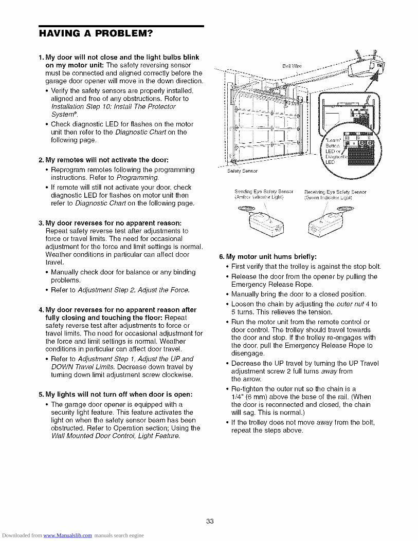
1. My door will not close and the light bulbs blinkon my motor unit: The safety reversing sensormust be connected and aligned correctly before thegarage door opener will move in the down direction.
• Verify the safety sensors are properly installed,aligned and free of any obstructions. Refer toInstallation Step 10: Install The ProtectorSysterrP.
• Check diagnostic LED for flashes on the motorunit then refer to the Diagnostic Chart on thefollowing page.
2. My remotes will not activate the door:
• Reprogram remotes following the programminginstructions. Refer to Programming.
• If remote will still not activate your door, checkdiagnostic LED for flashes on motor unit thenrefer to Diagnostic Chart on the following page.
3. My door reverses for no apparent reason:Repeat safety reverse test after adjustments toforce or travel limits. The need for occasionaladjustment for the force and limit settings is normal.Weather conditions in particular can affect doortravel.
• Manually check door for balance or any bindingproblems.
• Refer to Adjustment Step 2, Adjust the Force.
4. My door reverses for no apparent reason afterfully closing and touching the floor: Repeatsafety reverse test after adjustments to force ortravel limits. The need for occasional adjustment forthe force and limit settings is normal. Weatherconditions in particular can affect door travel.
• Refer to Adjustment Step 1, Adjust the UP andDOWN Travel Limits. Decrease down travel byturning down limit adjustment screw clockwise.
5. My lights will not turn off when door is open:
• The garage door opener is equipped with asecurity light feature. This feature activates thelight on when the safety sensor beam has beenobstructed. Refer to Operation section; Using theWall Mounted Door Control, Light Feature.
Bell Wire
\
Safety Sensor
Sending Eye Safety Sensor(Amber Indicator Light)
Receiving Eye Safety Sensor(Green Indicator Light)
,,;
/;
6. My motor unit hums briefly:
• First verify that the trolley is against the stop bolt.
• Release the door from the opener by pulling theEmergency Release Rope.
• Manually bring the door to a closed position.
• Loosen the chain by adjusting the outer nut 4 to5 turns. This relieves the tension.
• Run the motor unit from the remote control ordoor control. The trolley should travel towardsthe door and stop. If the trolley re-engages withthe door, pull the Emergency Release Rope todisengage.
• Decrease the UP travel by turning the UP Traveladjustment screw 2 full turns away fromthe arrow.
• Re-tighten the outer nut so the chain is a1/4" (6 mm) above the base of the rail. (Whenthe door is reconnected and closed, the chainwill sag. This is normal.)
• If the trolley does not move away from the bolt,repeat the steps above.
33
Downloaded from www.Manualslib.com manuals search engine

Bell Wire
Safety Sensor
Diagnostic Chart
Safety sensors wire open(broken or disconnected).
OR
Safety sensors wireshorted or black/whitewire reversed.
Door control orwire shorted.
Safety Sensorsslightly misaligned(dim or flashing LED).
Motor overheated orpossible RPM sensorfailure. Unplug to reset.
Motor Circuit Failure.Replace ReceiverLogic Board.
Your garage door opener is programmed withself-diagnostic capabilities. The "Learn" button/diagnosticLED will flash a number of times then pause signifying ithas found a potential issue. Consult Diagnostic Chart below.
"e
e
Symptom: One or both of the Indicator lights on the safety sensors donot glow steady.• Inspect sensor wires for a short (staple in wire), correct wiring polarity
(black/white wires reversed), broken or disconnected wires, replace/attachas needed.
• Disconnect all wires from back of motor unit.
• Remove sensors from brackets and shorten sensor wires to 1-2 ft (30-60 cm)from back each of sensor.
• Reattach sending eye to motor unit using shortened wires. If sending eyeindicator light glows steadily, attach the receiving eye.
• Align sensors, if the indicator lights glow replace the wires for the sensors. Ifthe sensor indicator lights do not light, replace the safety sensors.
Symptom: LED is not fit on door control
• Inspect door control/wires for a short (staple in wire), replace as needed.• Disconnect wires at door control, touch wires together. If motor unit activates
replace door control.• If motor unit does not activate, disconnect door control wires from motor unit.
Momentarily short across red and white terminals with jumper wire. If motorunit activates, replace door control wires.
"e Symptom: Sending indicator light glows steadily, receiving indicator lightis dim or flashing.• Realign receiving eye sensor, clean lens and secure brackets.
• Verify door track is firmly secured to wall and does not move.
eSymptom: Motor has overheated; the motor unit does not operate ortrolley is stuck on stop bolt = Motor unit hums briefly; RPM Sensor =Short travel 6-8" (15-20 cm).• Unplug unit to reset. Try to operate motor unit, check diagnostic code.
• If it is still flashing 5 times and motor unit moves 6-8" (15-20 cm), replace RPMsensor.
• If motor unit doesn't operate, motor unit is overheated. Wait 30 minutes andretry. If motor unit still will not operate replace logic board.
"0 Symptom: Motor unit doesn't operate.• Replace logic board because motor rarely fails.
34
Downloaded from www.Manualslib.com manuals search engine

PROGRAMMING
NOTICE: If this Security.l_ garage door opener is operated with a non-rolling code transmitter, the technicalmeasure in the receiver of the garage door opener, which provides security against code-theft devices, will becircumvented. The owner of the copyright in the garage door opener does not authorize the purchaser orsupplier of the non-rolling code transmitter to circumvent that technical measure,
Your garage door opener has already been programmed at the factory to operate with your hand-held remotecontrol, The door will open and close when you press the large push button.
Below are instructions for programming your opener to operate with additional Security+ ® remote controls,
To Add or Reprogram a Hand.held Remote Control
USING THE "LEARN" BUTTON
To Erase All Codes From Motor
Unit Memory
To deactivate any unwanted remote, 151first erase all codes:
Press and hold the "learn" button onmotor unit until the learn indicatorlight goes out (approximately 6 seconds), All previouscodes are now erased. Reprogram each remote orkeyless entry you wish to use.
1, Press and release the "learn"button on the motor unit. Thelearn indicator light will glowsteadily for 30 seconds,
2, Within 30 seconds, press andhold the button on the hand-heldremote* that you wish to operateyour garage door.
*3-Function Remotes
If provided with your garage door opener, the largebutton is factory programmed to operate it. Additionalbuttons on anySecurity+ ®3-Functionremote or compactremote can beprogrammed to operateother Security+ ®garagedoor openers.
3. Release the button when themotor unit lights blink, It haslearned the code, If light bulbs arenot installed, two clicks will beheard,
/
35
Downloaded from www.Manualslib.com manuals search engine

To Add, Reprogram or Change a Keyless Entry PIN
NOTE: Your new Keyless Entry must be programmed to operate your garage door opener.
USING THE "LEARN" BUTTON
1. Press and release the "learn"button on motor unit, The learnindicator light will glow steadily for30 seconds.
2. Within 30 seconds, enter a fourdigit personal identificationnumber (PIN) of your choice onthe keypad, Then press and holdthe ENTER button.
3, Release the button when themotor unit lights blink, It haslearned the code. If light bulbs arenot installed, two clicks will beheard,
/
To change an existing, known PIN
If the existing PIN is known, it may be changed by oneperson without using a ladder,
1. Press the four buttons for the present PIN, thenpress and hold the # button,The opener light will blink twice. Release the #button,
2. Press the new 4-digit PIN you have chosen, thenpress ENTER,
The motor unit lights will blink once when the PIN hasbeen learned.
Test by pressing the new PIN, then press ENTER, Thedoor should move,
To set a temporary PIN
You may authorize access by visitors or service peoplewith a temporary 4-digit PIN. After a programmednumber of hours or number of accesses, this temporaryPIN expires and will no longer open the door, It can beused to close the door even after it has expired, To seta temporary PIN:
1. Press the four buttons for your personal entry PIN(not the last temporary PIN), then press and hold the
button,
The opener light will blink three times, Release thebutton,
2. Press the temporary 4-digit PIN you have chosen,then press ENTER,
The opener light will blink four times,3. To set the number of hours this temporary PIN will
work, press the number of hours (up to 255), thenpress _.
OR
3. To set the number of times this temporary PIN willwork, press the number of times (up to 255), thenpress #,
The opener light will blink once when the temporary PINhas been learned,
Test by pressing the four buttons for the temporary PIN,then press ENTER. The door should move, If thetemporary PIN was set to a certain number of openings,remember that the test has used up one opening,Toclear the temporary password, repeat steps 1-3, settingthe number of hours or times to 0 in step 3,
36
Downloaded from www.Manualslib.com manuals search engine

REPAIR PARTS
Rail Assembly Parts
3
KEYNO.
123456
PARTNO. DESCRIPTION
4A1008 Master link kit
41C5141-1 Complete trolley assembly
41A5665 Complete rail
144C56 Idler pulley41A5807 Chain and cable
12D598-1 "U" bracket
NOT SHOWN
183A163 Wear pads
Installation Parts
D1
KEYNO.
123
45
67
8
9
10
11
1213
1
PARTNO.
41A4166
10A20
41A6140-1
29B13741A2828
41A504741B4494-1
41A5047-2
178B35
41A5034
41A5266-1
178B3412B776
41A5258-10
114A3125
DESCRIPTION
Lighted door control button3V 2032 Lithium battery3-Function remote control case
(no circuit board)
Visor clipEmergency release rope and handleassembly
Header bracket w/clevis pin & fastener2-Conductor bell wire: white & white/red
Door bracket w/clevis pin & fastenerCurved door arm section
Safety sensor kit: receiving andsending eyes with 3' (0.9 m)2-conductor bell wire attached
Safety sensor bracket
Straight door arm section
Hanging bracketNOT SHOWN
Assembly & Installation hardware bag(see page 7)Owner's manual
37
Downloaded from www.Manualslib.com manuals search engine

Motor Unit Assembly Parts
18 17
16 15
(Down) LIMIT SWITCHBrown Contact ASSEMBLY
Contact Contact Wire
I
I
3
1
1412
11
5 '
7
i
i
Ii___ ,-
KEY PARTNO. NO.
1 41A5615
2 41C4220A
3 41A2817
4 41B4245
5 41A4352
6 4A1344
7 108D58-2
8 30B5329 12A373
10 41A3150
KEY PARTDESCRIPTION NO. NO.
Chain spreader 11 41D3058
Gear and sprocket assy.Complete with:Spring washer, Thrust washer,Retaining ring, Bearing plate,Roll pins (2), Drive gear and 12 41D328-4worm gear, Helical gear 13 41A2818w/retainer and grease 14 41D3452
Drive/worm gear kit w/grease 15 41C4398ARoll pins (2) 16 41C4246Line cord
17 41A2826End panel 18 41A2822ALight socket 19 41A5021-3H-315Lens
Capacitor- 1/2 HPCapacitor bracketTerminal block w/screws 20 41A3691
41A2825
DESCRIPTION
Universal replacement motorand bracket assemblyComplete with: Motor, worm,bracket, bearing assembly,RPM sensor
Cover - 1/2 h.p.Limit switch drive and retainer
Limit switch assembly
RPM sensor assembly
Wire harness assy. w/plug
Shaft bearing kit
Interrupter cup assy.
Receiver logic board assy.Complete with:Logic board, end panel w/alllabels
End panel w/all labelsNOT SHOWN
Opener assembly hardware kit(includes screws notdesignated by a number inillus.)
38
Downloaded from www.Manualslib.com manuals search engine

ACCESSORIES
139.53702
/Emergency Key Release:
Required for a garage with NOaccess door. Enables homeowner toopen garage door manually fromoutside by disengaging trolley.
139.53726
139.53727
8 Foot (2.4 m) Rail Extension:
To allow an 8 foot (2.4 m) door toopen fully.
10 Foot (3 m) Rail Extension:
To allow a 10 foot (3 m) door to openfully.
139.53753
139.53752
139.53754
SECURITY÷ _ 3-Function RemoteControl:
Includes visor clip.
SECURITY÷ * Compact3-Function Remote Control:
With loop for attaching key ring.
SECURITY÷ _ Keyless Entry:Enables homeowner to operate garagedoor opener from outside by entering apassword. Also can add a temporarypassword for visitors or service persons.
139.53589
41A5281
139.53709
Support Brackets:
For finished ceilings or whereadditional support is required, basedon garage construction. Includesbrackets and fastening hardware.
Extension Brackets:(Available only through SearsParts & Service)
(Optional) For safety sensorinstallation onto the wall or floor.
Door Clearance Brackets:(For Sectional Doors Only)Replaces top brackets and rollers ondoor to reduce height of door travel.For use when installing opener ingarage with low headroom clearance.
139.53687
139.53749
Premium Control Console:
Provides a lock feature to preventoperation of garage door from portableremotes. A light feature controls theopener lights. Can be used to programthe opener to accept additional remotes.
Plug-In Light Control:
Enables homeowner to turn on a lamp,television or other appliance from car,bedside, or anywhere in the home witha remote.
WARRANTY
SEARS WARRANTYFULL 1 YEAR WARRANTY ON GARAGE DOOR OPENER
For 1 year from the date of purchase, Sears will repair this Garage Door Opener, free of charge, if defective in material or workmanship.
LIMITED WARRANTY ON MOTOR
I/2HP MOTOR: After 1 year and through 4 years, if the motor on this Garage Door Opener is defective, Sears will furnish areplacement motor, free of charge. You pay for labor.
LIMITATION ON LIABILITYSEARS WILL NOT BE LIABLE FOR LOSS OR DAMAGE TO PROPERTY OR ANY INCIDENTAL OR CONSEQUENTIAL LOSS OREXPENSE FROM PROPERTY DAMAGE DUE DIRECTLY OR INDIRECTLY TO THE USE OF THIS PRODUCT. Some states do notallow the exclusion or limitation of incidental or consequential damages, so the above limitation or exclusion may not apply to you.This warranty does not cover light bulbs or repair parts necessary because of operator abuse or negligence, including the failure toinstall, adjust and operate this garage door opener according to instructions contained in the owner's manual.WARRANTY SERVICE IS AVAILABLE BY CONTACTING THE NEAREST SEARS SERVICE CENTER IN THE UNITED STATES.
This warranty applies only while this product is in use in the United States.This warranty gives you specific legal rights, and you may also have other rights which vary from state to state.
Sears, Roebuck and Co., Dept. 817WA, Hoffman Estates, IL 60179
39
Downloaded from www.Manualslib.com manuals search engine

CONTENIDO
Introducci6n 2-7
Revisi6n de los simbolos y terminos de seguridad ......... 2
Preparaci6n de la puerta de su cochera ......................... 3
Herramientas necesarias ................................................. 3
Planificaci6n ................................................................. 4-5
Inventario de la caja de cart6n ........................................ 6
Inventario de piezas ......................................................... 7
Montaje 8.11
Monte el riel y instale el trole ........................................... 8
Fije el riel al motor e instale la polea Ioca ....................... 9
Instale la cadena y cable .............................................. 10
Apriete la cadena ........................................................... 11
Instalaci6n 11.26
Instrucci6nes de seguridad para la instalaci6n .............. 11
Determine d6nde va a instalarla mensula del cabezal .................................................. 12
Instale la mensula del cabezal ...................................... 13
Coloque el riel en la mensula del cabezal ..................... 14
Coloque el abridor en posici6n ...................................... 15
Cuelgue el abridor ......................................................... 16
Instale la unidad de control de la puerta ....................... 17
Instale la luz ................................................................... 18
Instale la manija y la cuerda de emergencia ................. 18
Requisitos para la instalaci6n electrica ......................... 19
Instale La Sistema de Protecci6n ® ........................... 20-22
Fije la mensula de la puerta ..................................... 23-24
Conecte el brazo de la puerta al trole ...................... 25-26
Ajustes 27.29
Ajuste el limite del recorrido .......................................... 27
Ajuste la fuerza .............................................................. 28
Pruebe el sistema de retroceso de seguridad ............... 29Pruebe La Sistema de Protecci6n ®................................ 29
Operaci6n 30.34
Instrucci6nes de seguridad para la operaci6n ............... 30
C6mo usar su abridor de puerta de cochera ................. 30
C6mo usar la unidad de control de pared ..................... 31
C6mo abrir la puerta manualmente ............................... 31
Mantenimiento de su abridor de puerta de cochera ......32
Si tiene algQn problema ................................................. 33
Tabla de diagn6stico ...................................................... 34
C6mo Programar el Abridor 35.36
C6mo agregar o reprogramar uncontrol remoto manual ................................................... 35
C6mo borrar todos los c6digos ...................................... 35Controles remotos de 3 funciones ................................. 35
C6mo agregar, reprogramar o cambiar unc6digo de entrada sin Ilave............................................ 36
Accesorios 37
Garantia 37
Nbmeros de Servicio Contratapa
INTRODUCClON
Revisi6n de los Simbolos y T_rminosde Seguridad
Este abridor de puerta de cochera ha sido diseRado y probado para un funcionamiento seguro, siempre y cuando se instale,se pruebe, se opere y se le de mantenimiento como se indica en este manual, cumpliendo a! pie de la letra con todas lasadvertencias e instrucciones generales aqui contenidas.
Mecanica
Electrica
Estas advertencias y/o simbolos de seguridad queaparecen en este manual le alertaran de que existe elriesgo de una lesion seria o de muerte si no se siguenlas instrucciones correspondientes. El peligro puede serelectrico (electrocuci6n) o mec_tnico. Lea las instruccionescon mucho cuidado.
Cuando vea esta palabra y/o simbolo de seguridad en estemanual, le alertara de que existe el riesgo de da_ar lapuerta de la cochera y/o el abridor si no se siguen lasinstrucciones correspondientes. Lea las instrucciones conmucho cuidado.
Downloaded from www.Manualslib.com manuals search engine
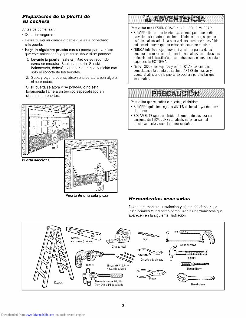
PreparaciOn de la puerta desu cochera
Antes de comenzar:
• Quite los seguros.
• Retire cualquier cuerda o cable que este conectadoa la puerta.
• Haga la siguiente prueba con su puerta para verificarque este balanceada y que no se atore ni se pandee:
1. Levante la puerta hasta la mitad de su recorridocome se muestra. Suelte la puerta. Siesta.balanceada, debera, mantenerse en esa posicion consolo el soporte de los resortes.
2. Suba y baje la puerta; observe si se atora con algo osi se pandea.
Si su puerta se atora o se pandea, o no estabalanceada Ilame a un tecnico especializado ensistemas de puertas.
Puerta seccional
Paraevitar una LESIONGRAVEo INCLUSOLA MUERTE:
• SIEMPREflame a un t_cnico profesional para que le d_servicio a su puerta de cochera si 6sta se atora, se pandea oest,. desbalanceada.Una puerta de cochera que no est_ bienbalanceadapuede que no retroceda como se requiere.
• NUNCAintente aflojar, mover ni ajustar la puerta de sucochera, los resortes de la puerta, los cables, las poleas, lasm_nsulas ni la tornilleria, pues todos estos elementos est_nbajo tension EXTREMA.
• Quite TODOSlos seguros y retire TODASlas cuerdasconectadasa la puerta de cochera ANTESde instalar yoperar el abridor de la puerta de cochera paraevitar quese enreden.
Paraevitar que se darien el puerta y el abridor:
• SIEMPREquite los seguros ANTESde instalar y/o de operarel abridor.
• SOLAMENTEopere el abridor de puerta de cochera concorriente de 120V,60Hz con objeto de evitar su realfuncionamiento y que el abridor se dafie.
Puerta de una sola piezaHerramientas necesarias
Durante el montaje, instalacion y ajuste del abridor, lasinstrucciones le indicaran como usar las herramientas queaparecen en la siguiente ilustraciOn.
Escalera
Niveldecarpinteria (opcional)
Cinta de medir
/Taladro Brocasde 3,16, 5/16
y 5/32 de pulgada
UO 7/16,9/16 y 1/4de pu'lgad'a
Lapiz
Cortadorade alambre
Sierra de mane
Destomillador
Llaveinglesa
Downloaded from www.Manualslib.com manuals search engine

Planificaci6n
Identifique la altura y el tipo de su puerta de cochera.Revise el area de su cochera y observe si alguna delas siguientes instalaciones corresponden a la suya.A veces se requieren materiales adicionales, asi que talvez sea conveniente tener esta hoja y las ilustracionescorrespondientes a mano cuando inicie la instalaci6n de suabridor.
Dependiendo de sus necesidades individuales, es posiblequeen algunos casos vaya a necesitar materiales oherramientas que no se incluyen con este producto.
• Instalaci6n Paso 1 - Observe la pared o el cielo rasojusto por encima de la puerta de la cochera. La mensuladel cabezal debe estar firmemente sujeta a los soportesde la estructura.
• Instalaci6n Paso 5 - Si el plaf6n o cielo raso de sucochera tiene acabado, es posible que necesite unamensula de soporte y/o mas pernos y tomilleria para lainstalaci6n.
• Instalaci6n Paso 10 - Dependiendo del tipo deconstrucci6n de su cochera, es posible que necesitemensulas de extensi6n o bloques de madera parainstalar los sensores.
• Instalaci6n Paso 10 - El montaje en e! piso del sensorque activa e! sistema de retroceso de seguridad podriarequerir piezas que no se incluyen.
).Hay otra puerta que de acceso a la cochera? Si no esasi, sera necesario contar con el sistema de llave deemergencia Modelo 53702. Vea la pagina de Accesorios.
Observe el punto donde la puerta hace contacto con elpiso. El espacio entre la base de la puerta y el piso nodebe exceder 6 mm (1/4 de pulgada). Si no es asi, secorre el riesgo de que el sistema de retroceso deemergencia no funcione correctamente. Vea Ajustes,Paso 3. Sera necesario reparar ya sea el piso o lapuerta.
INSTALACION CON UNA PUERTA SECCIONAL
Si tiene una puerta de acero, aluminio, fibra de vidrio ocon paneles de vidrio, necesitara refuerzos verticales yhorizontales en la puerta. (Instalaci6n, Paso 11.)
El abridor se debe instalar por encima del centro de lapuerta, pero si existe algOn resorte de tension o placa deapoyo en el paso de la mensula del cabezal, se puedeinstalar hasta a 1.22 m (4 pies) a la derecha o a laizquierda del centro de la puerta. Vea Instalaci6n, Pasosdel 1 a111.
• Si su puerta es de mas de 2.13 m (7 pies) de altura, veaExtensiones de riel en la secci6n de Accesorios.
INSTALACION CON UNA PUERTA SECCIONAL
Losrefuerzosverticalesy horizontalessonnecesarios para las puertasde cocheradematerialesmas livianos(libra de vidrio, acero,aluminio,o puertas con paneles de vidrio).
Vea[a pagina23, dondeencontraramas detalies.
Pared delantera
\ i
La holguraen latensionde la cadenaes normal
cuandola puerta seencuentracerrada
CIELO RASOCON ACABADO
Se requiere mensulade
soporte y tomillososujetadores.Veala pagina 16.
Riel
Resorte de extensi6n0
Resortede torsion
Unidad del motor
Linea Central
Verticalde la
Puerta de Garaje
Unidaddecontrol de
la puerta,instalada
en la pared
Puerta deacoeso
Sensor del sistema
de retrocesode seguridad
Elespacio entre la base de
[a puerta y el piso no debedeexceder6 mm (1/4de puig.).
Sensordel sistema
de retrocesode seguridad
P_edde antera
Pt ._rta
de laco :hera
Mensuladel cabezal ENPOSIClON CERRADA
/ Pemo de,/ paro de1trole Trole
Resor ede la / /
poerta_ /o/ I Cadenacochera /o/,, I
I Cuerda y rnanija
_ /_ueua I del sistemade
/o°7 liberacion_--_ " de emergenciax_ arazoN_ I \ curvode
I Mensula la puerta
_[[ dela
Ij puerta
Downloaded from www.Manualslib.com manuals search engine

Planificaci6n (continba)
INSTALACION CON PUERTAS DE UNA SOLA PIEZA
• Generalmente una puerta de una sola pieza no requiererefuerzos adicionales. Si usted tiene una puerta dematerial liviano y quiere reforzarla, consulte lainformaci6n respecto a puertas seccionales, contenidaen Instalaci6n, Paso 11.
• Dependiende del disefie de su puerta, tal vez necesitepiezas de mentaje adicionales para la mensula de lapuerta (Paso 11).
Sin un sistema de retroceso de seguridad que funcionedebidamente, al cerrar la puerta de la cochera se corre elriesgo de que las personas (y en particular los nifiospequefios) sufran LESIONESGRAVESo INCLUSOLA MUERTE.
• El espacio entre la basede la puerta de la cochera y el pisoNODEBEexceder6mm (1/4 depulgada).De noserasi,elsistema de retroceso de seguridad nova a funcionardebidamente.
• El piso o la puerta de la cochera SE DEBEreparar paraeliminar este espacio.
PUERTA DE UNA SOLA PIEZASIN CARRIL
-"_ Pared delantera
Sensordel sistemade
retrocesode seguddad
ELO RASOCON ACABADO
Serequiere mensulade soportey tornillos osujetadores.Vea la pagina 16.
La holgaraen la tensi6nde la cadenaes normal
euandola puerta se Unidaddel motor
encuentracerrada
Unidad de centre[de la puerta,/ instalada en la pared
PuertadeaccesoPemo de paro
0
Sensordel sistemade
El espacioentre la base retrocesode seguddadla puerta y el piso no debedeexceder6 mm (1/4de pulg.)
EN POSICIONCERRADA
I Cable Trole
J
Braze Braz0recto de curvela puerta de la
Puertade puerta _
la cochera
Cuerday manijadel sistemadeIiberacionde
emergencia
PUERTA DE UNA PIEZA CON CARRIL
J El espacioentre la base deSensor del sistemade la puerta y el piso no debe
retroceso de seguddad exceder6 mm (1/4de pulg.).
Puertadeacceso
c
Sensor delsistema de
retrocesode seguridad
Paredelantera
ENPOS_C_ONCERRADA
Peme de pare Cabledel trole | I
,_ .? IMensula Brazo,
del cabezal curvoae _ /la pueria j /
ooooooooooo)J
'_.. U6nsula de Ila puerta Brazorecto de_/_ la puerta7/_,-- Puerta deY/'_ la cochera
Cadena
Riel
Cuerda y manija-- del sistemade
liberacion
de emergencia
Downloaded from www.Manualslib.com manuals search engine

Inventario de la Caja de Cart6n
Su abridor viene empacado en una caja de carton quecontiene el motor y las piezas que se muestran en lasiguiente ilustraci6n. Tome nota de que los accesoriosdependeran del modelo que haya comprado. Si faltaalguna pieza, revise con cuidado el material de empaqueya queen ocasiones las piezas se atoran en el mismo.
Toda la tornilleria y las piezas necesarias para el montaje einstalacion de su puerta se ilustran en la siguiente pagina.Conserve la caja y los materiales de empaque hasta que lainstalacion y e! ajuste se hayan terminado.
Bot6nde control de Japuerta
Control remotode tresfunciones,con clip para el visor (2)
Unidad del motor con Line lente
Poleade la cadena
sDesplegadorde Cadena
Secci6ndelanteradel riel (cabezal)
Mensuladel cabezal
Seccionescentraly posteriordel riel
Trole
Mensula de la puerta _,/
Secci6ncurva del
brazo de la puerta
Doscables conductores
de campana.Blancoy blanco/rojo
M_nsulaspara colgar
Dosm_nsulas para el sensordel sistemade retrocesode seguridad(2)
Dossensoresdel sistema deretrocesode seguridad(un ojo transmisory un ojo receptor) conectadosaun cablede campanade dosconductores.Blancoy blancoy negro
Etiquetasdeseguridadyliteratura
Seccionrectadelbrazo dela puerta
Downloaded from www.Manualslib.com manuals search engine

Inventario de Piezas
Antes de la instalaci6n, organice todas las piezas en grupos como se muestra en la siguiente ilustraci6n.
TORNILLERJA Y PIEZAS PARA EL MONTAJE
©Tuerca de Arandela de Tuerca de
1/4-20 (2) 3/8 pub. (1) 3/8pub. (1)
Perno de
1/4-20xl-3/4 pulg. (2)
Fbcha roscadadel trole (1)
i
d_Enlace maestro (2)
Pemo Ioco (1)
TORNILLER|A Y PIEZAS PARA LA INSTALACION
Pernode coche
de 1/4-20xl/2 pulg. (2)Tuercade mariposa1/4-20 pulg. (2)
l I I EI I I I EE_)Tornillode cabeza cuadrada
de 5/16-8xl-5/8 de pulg. (2)
de 5/16-18xl-7/8 pulg. (2)
Perno de coche de 5/16-18x2-1/2pulg. (2)
O ©Anillo sujetador(3) Tuerca de
5/16-18puJg.(8)
E D @Perno hexagonalde 5/16-18x7/8pub. (4) Arandela de 5/16 pub. (7)
Taquete para murofalso (2)
Manija
Grapaconaislamiento(30)
_ IIIIIIIIIIIIIIIIIIIII
Tornillo de 6-82xl pub. (2)
Espaciador(2)
olPasadorde chaveta Pasadorde chaveta Pasadorde chaveta
de 5/16x1-1/2pulg. (1) de 5/16xl pulg. (1) de 5/16x1-1/4pulg. (1)
Cuerda
Downloaded from www.Manualslib.com manuals search engine

MONTAJE, PASO 1Monte el Riel e instale el Trole
No encienda ni use el abridor hasta que Ilegue alpaso de la instalacion correspondiente, de otramanera corre el riesgo de complicar el proceso deinstalacion.
El riel delantero tiene una "ventana" cortada en elextremo de la puerta (vea la ilustracidn). El orificio quese encuentra por encima de esta ventana es masgrande en la parte superior del riel queen/a parteinferio_ Hay un orificio mas peque_o que se encuentra a8.9 cm (3-1/2 pulg.) y esta cerca de la orilla del riel. Gireel riel posterior de manera que tenga un orificio similarcerca de la orilla opuesta, mas o menos a 12 cm (4-3/4pulg.) del extremo.
1. Quite el brazo recto de la puerta, las mensulas paracolgar y el pasador de chaveta que viene empacadodentro del riel delantero y p6ngalos a un lado parausarlos en el Paso 5 y 12 de la Instalaci6n. NOTA:Para no sufrir una LESION al desempacar el riel,mueva con cuidado el brazo recto de la puerta queesta almacenado dentro de la seccidn de riel.
2. Alinee las secciones del riel sobre una superficieplana exactamente como se indica y luego deslice losextremos ma.s peque_os dentro de los mas grandes.Las pesta_as que se encuentran a Io largo de loslados del rie! se van a ajustar en su lugar.
ParaevitarQUESEPELLIZQUE,conservelos manosy ded0slejosdelasjuntascuandomonteel reil.
3. Coloque el motor sobre el material de empaque paraproteger la cubierta del mismo y apoye el extremoposterior del riel encima. Para que le resulte mascomodo, ponga algOn tipo de apoyo bajo e! extremodelantero del riel.
4. Ponga en el riel un destornillador como tope temporaldel trole a 20 cm (8 pulg.) del centro del orificio de lapolea Ioca, como se indica en la ilustraci6n.
5. Revise y cerci6rese de que haya 4 cojinetes dedesgaste dentro del trole interno, estos cojinetes son depla.stico. Si los cojinetes se han soltado durante eltransporte, revise todo el material de empaque. Pongalos cojinetes de desgaste en su lugar como se indica.
6. Deslice el trole a Io largo del riel desdeel extremo posterior hacia el destornillador.
Trole
Extremomgs
pequd_o
MANTENGA EL" ORIFICIO MAS
GRANDEHACIAARIBA
RIEL DELANTERO
(PARTESUPERIOR)
Extremomas
pequefio
Extremomas
peque_o
ieIes posteriores(AL MOTOR}
Extremomas
pequeSo
Trole interno
Troleextemo\
Cojinetesde desgaste
Downloaded from www.Manualslib.com manuals search engine
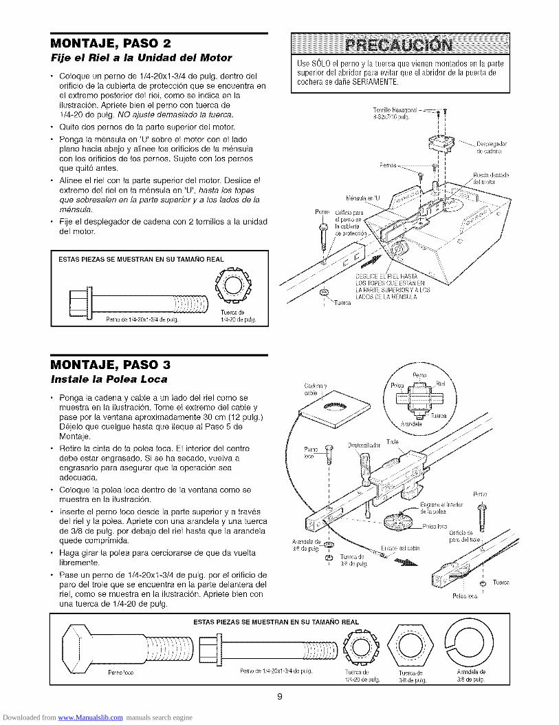
MONTAJE, PASO 2Fije el Riel a la Unidad del Motor
Coloque un perno de t/4-20xl-3/4 de pulg. dentro delorificio de la cubierta de proteccion que se encuentra enel extremo posterior del riel, como se indica en lailustraci6n. Apriete bien el perno con tuerca de1/4-20 de pulg. NO ajuste demasiado la tuerca.
Quite dos pernos de la parte superior del motor.
Ponga la mensula en 'U' sobre el motor con el ladopiano hacia abajo y alinee los orificios de la mensulacon los orificios de los pernos. Sujete con los pernosque quit6 antes.
Alinee el riel con la parte superior del motor. Deslice elextremo del riel en la mensula en 'U', hasta los topesque sobresalen en la parte superior y a los lades de lamensula.
Fije el desplegador de cadena con 2 tornillos a la unidaddel motor.
Use SOLOel perno y la tuerca que vienen montados en la partesuperior del abridor para evitar que el abridor de la puerta decochera se dafie SERIAMENTE.
Pernos_
M_nsulaen 'U'
Pemo Orificio paraI el perno en
la cubierta
de protecci@
I I
_'_ esplegadorde cadena
iRuedadentada
/del motor
ESTAS PIEZAS SE MUESTRAN EN SU TAMAI_IO REAL
ili _i_'/i///"//'J Tuerca de
Perno de 1/4-20xl-3/4 de pulg. 1/4-20de pulg.
_Tuerca
LOSTOPESQUE ESTANENLA PARTESUPERIORY A LOSLADOSDELA MENSULA
MONTAJE, PASO 3Instale la Polea Loca
Ponga la cadena y cable a un lado del riel como semuestra en la ilustracion. Tome el extremo del cable ypase por la ventana aproximadamente 30 cm (12 pulg.)Dejelo que cuelgue hasta que Ileque al Paso 5 deMontaje.
Retire la cinta de la polea Ioca. El interior del centrodebe estar engrasado. Si se ha secado, vuelva aengrasarlo para asegurar que la operaci6n seaadecuada.
Coloque la polea Ioca dentro de la ventana como semuestra en la ilustracion.
Inserte el perno Ioco desde la parte superior y a travesdel riel y la polea. Apriete con una arandela y una tuercade 3/8 de pulg. por debajo del riel hasta que la arandelaquede comprimida.
Haga girar la polea para cerciorarse de que da vueltalibremente.
Pase un perno de 1/4-20xl-3/4 de pulg. por el orificio deparo del trole que se encuentra en la parte delantera delriel, como se muestra en la ilustraci6n. Apriete bien conuna tuerca de 1/4-20 de pulg.
Cadenaycable
_) Tuercade3/8 de pulg.
Perno
Arandela
Destornillador Trole
Perno
Engraseelinterior
_ e la polea
.... _PolealocaOrificio de
paro del troEnlacedelcable
Perno Ioco
ESTAS PIEZAS SE MUESTRAN EN SU TAMAI_IO REAL
©Perno de 1/4-20xl-3/4 de pulg. Tuercade
1/4-20 de pulg.Tuercade
3/8 de pulg.
Poleaiota
Arandelade
3/8de pulg.
Downloaded from www.Manualslib.com manuals search engine
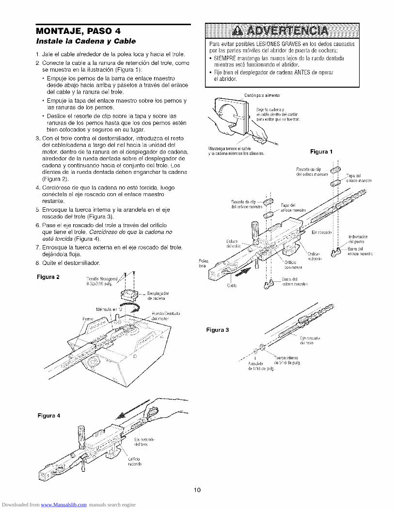
MONTAJE, PASO 4Instale la Cadena y Cable
1. Jale el cable alrededor de la polea Ioca y hacia el trole.
2. Conecte la cable a la ranura de retencion de! trole, comose muestra en la ilustraci6n (Figura 1):
• Empuje los pernos de la barra de enlace maestrodesde abajo hacia arriba y p4tselos a traves del enlacedel cable y la ranura del trole.
• Empuje la tapa de! enlace maestro sobre los pernos ylas ranuras de los pernos.
• Deslice el resorte de clip sobre la tapa y sobre lasranuras de los pernos hasta que los dos pernos estenbien colocados y seguros en su lugar.
3. Con el trole contra el destomillador, introduzca el restodel cable/cadena a largo del riel hacia la unidad delmotor, dentro de la ranura en el desplegador de cadena,alrededor de la rueda dentada sobre el desplegador decadena y continuando hacia el conjunto del trole. Losdientes de la rueda dentada deben enganchar la cadena(Figura 2).
4. Cerci6rese de que la cadena no este torcida, luegoconectela al eje roscado con el enlace maestrorestante.
5. Enrosque la tuerca interna y la arandela en el ejeroscado del trole (Figura 3).
6. Pase el eje roscado del trole a traves del orificioque tiene el trole. Cercidrese de que la cadena noeste torcida (Figura 4).
7. Enrosque la tuerca externa en el eje roscado del trole,dejandola floja.
8. Quite e! destornillador.
Figura 2 Tornillo Hexagonal,_ _
-32xTJ16pulg',_ esplegador
de cadena
Mensula en '_Rueda Dentada
Perno
Paraevitar posibles LESIONESGRAVESen los dedos causadaspor las partes m6viles del abridor de puerta de cochera:
• SIEMPREmantenga las manos lejos de la rueda dentadamientras est6funcionando el abridor.
• Fije bien el desplegador de cadena ANTESde operarel abridor.
Carton para alimentar
oar,6o
e setuerzan.
Mantengatenses el cabley la cadenamientras los alimente. Figura 1
i
Resortede clip
del enlace maestro "_ i Tapa del
enlace maestro
Cable
Figura 3
Eje roscadodel trole
Tuereainterna
Arandela de 5/16 de pulg,
de 5/16de pulg,
Figura 4
Eje roscadodel trole
Orificioredondo
10
Downloaded from www.Manualslib.com manuals search engine

MONTAJE, PASO 5Apriete la Cadena
• Gire la tuerca interna y ajuste la arandela; baje ambaspor el eje roscado del trole alejandolas del trole
• Para apretar la cadena gire la tuerca externa en ladirecci6n que se indica (Figura 1)
• Una vez que la cadena este aproximadamente a 6 mm(1/4 de pulg) por encima de la base del riel en su puntomedio vuelva a apretar la tuerca interna para asegurarel ajuste
Si la cadena queda demasiado floja la rueda dentadapuede hacer ruido
Una vez terminada la instalaci6n es posible que observeque la cadena cuelga un poco cuando la puerta estacerrada pero esto es normal Si la cadena regresa a laposici6n que se ilustra en la Figura 2 cuando la puertaesta abierta no vuelva a ajustar la cadena
NOTA: En el futuro, cuando le de mantenimientoSIEMPRE tire de la manija de emergencia paradesconectar el trole antes de ajustar la cadena
NOTA: Es posible que la cadena se afloje despues delPaso 3 de Ajustes (Pruebe el Sistema de retroceso deseguridad) Verifique que la tensiSn sea la debida yreajuste la cadena si es necesario Luego repita elPaso 3 de Ajustes
Ya termino de armar su abridor de puerta de cochera.Lea les siguientes advertencias antes de continuar ala secci6n de instalaci6n.
Figura 1
Figura 2
Paraapretar]]Jerca Ejeroscadoexterna Arandela del trole
tCadena
i
Basedel riel Mitad del riel
INSTALACION
INSTRUCCIONES IMPORTANTES PARALA INSTALACION
Para reducir el riesgo de una LESION GRAVE ola MUERTE:
1. LEAY SIGAAL PIEDE LA LETRATODASLASINSTRUCCIONESPARA LA INSTALACION.
2. Instale el abridor de puerta de cochera s61osi la puerta de lacochera est,. debidamente balanceaday lubricada. Si la puertano est_ debidamente balanceadaes posible que no retrocedacuando se requiera, Io que podria ocasionar una LESIONGRAVEo INCLUSOLA MUERTE.
3. Todas las reparaciones de los cables, resortes y otras piezaslas DEBEIlevar a cabo un t6cnico especializado en sistemasde puertas, ANTESde instalar el abridor.
4. Quite todos los seguros y retire todas las cuerdas conectadasa la puerta de la cochera ANTESde instalar el abridor para deevitar que se enreden.
5. Instale el abridor de la puerta de cochera a una distaocia de2.13 m (7 pies) del piso.
6. Monte la manija de liberaci6n de emergencia a una distanciade 1.83 m (6 pies) del piso.
7. NUNCAconecteel abridor de la puerta decochera a una fuentede energiael6ctrica hasta queasi se indique.
8. NUNOAIlevepuestos relojes, anillos ni ropa muy flojamientras est_ instalando odando servicio al abridor, puespodrian atorarse en la puerta de la cochera o en losmecanismos del abridor.
9. Instale el control de pared de la puerta de cochera:• de manera que quede a lavista desde la puerta de
la cochera.
• fuera del alcance de los nifios y a una altura minima de5 pies (1.5 m).
• lejos de todas las partes m6viles de la puerta.10. Coloquelacalcomaniaqueadviertesobreel riesgodeatraparse
cercadel controlde lapuertade la cochera,en lapared.11. Coloque la calcomania que contieoe la prueba de retroceso
de seguridad y liberaciOnde emergencia a plena vista en laparte interior de la puerta de la cochera.
12. AI concluir la instalaci6n, pruebe el sistema de retroceso deseguridad. La puerta DEBEretroceder al entrar en contactocon un objeto de 3.8 cm (1-1/2 de pulg.) o bien con unpedazode madera de 5x10 cm (2x4 pulg.) puesto pianosobre el piso.
11
Downloaded from www.Manualslib.com manuals search engine

I NSTALACl ON, PASO 1 INSTALACI6NOPCIONALDELA MENSULA DEL eABEZALEN EL ClELO RASODetermine ddnde va a instalar
la M_nsula del Cabezal Cielorasosin acabado
ParaevitarunaposibleLESIONGRAVEo INCLUSOLAMUERTE:• Lam6nsuladelcabezalDEBEquedarRiGIDAMENTEsujeta
alsoporteestructuralen la pareddelanterao enelcieloraso,deno serasies posiblequela puertadelacocheranoretrocedacuandose requiera.NOinstalela m_nsuladelcabezalen murosraises.
• SeDEBENusarsujetadoresparaconcretesi el montajedelam6nsuladelcabezalo delpedazodemaderade5x10cm(2x4 pulg.)sehaceenmamposteria.
• NUNCAtratedeaflojar,moverni ajustarlapuertadelacochera,los resortes,los cables,las poleas,las m_nsulasnila tornilleria,puestodasestaspiezasestAnbajounatensionEXTREMA.
• SIEMPREIlameaunt_cnicoespecializadoensistemasdepuertassi la puertadecocherase pandea,seatorao siestAdesbalanceada.Unapuertadecocheraquenoest6balanceadapuedenoretrocedercuandoserequiera.
El proceso de instalaci6n varfa dependiendo de losdiferentes tipos de puerta de cochera. Siga lasinstrucciones que correspondan a su puerta.
1. Cierre la puerta y marque la linea central vertical delinterior de la puerta.
2. ContinOe marcando esta linea hacia arriba hasta Ilegara la pared delantera, per encima de la puerta.
Es poeible instalar la m_nsula del cabezal hasta unadistancia maxima de 1.22 m (4 pies) a cada lade delcentre de la puerta, pero unicamente ei un reeortede torsion o un placa central de apoyo se encuentraen el recorrido. Tambien cuando el espacio esreducido, se puede instalar la meneula en el cieloraso o plafon de la cochera (vea la pagina 13).(Asimismo, se puede instalar invertida sobre lapared ei ee necesario, eeto le dara aproximadamente1 cm (1/2 de pulg.) de espacio).
Si necesita instalar la mensula del cabezal en unpedazo de madera de 5x10 cm (2x4 pulg.) (ya sea en lapared o en el techo), use tornillos de cabeza cuadrada opijas (no se incluyen) para sujetar el pedazo de maderaa los soportes estructurales, come se indica aqui yen lapagina 13.
3. Abra la puerta hasta el punto mas alto de su recorridocome se muestra. Marque una linea horizontal queintersecte en la pared delantera y adel punto mas altodel recorrido:
• 5 cm (2 pulg.) per encima del punto mas alto en elcase de puertas seccionales y puertas de una solapieza con riel.
• 20 cm (8 pulg.) per encima del punto mas alto en elcase de puertas de una sola pieza sin riel.
A esta altura, el extreme superior de la puerta tendrasuficiente espacio para su recorrido.
NOTA: Si el n#mero total de cenffmetros excede la
altura disponible en su cochera, use la altura maximaposible o consulte la pagina 13 para la Instalacidn en elciele rase e plafdn.
Pareddelantera
I Paredde[anteracm (2 pu[g.) zCam I
Punto m_saltode[recorrido
Puerta
Puerta eeoeionaI con earri[ curve
Pared deIantera
20 cm (8 puig,)
Puertade[ recemdo
Tornilleriade[montallte
Puerta de uaa sola pieza sin carri[:tomiHeria de[ montante
Linea centralvertical de [a
puerta de garaje\
Pedazode maderade 5x10 cm (2x4 pulg.)
Soportes dela estructura
Pareddelantera
_,_:-_51ZCCC-_ Cardl
Punlo mas alto/
del recorrido
Paerta de uaa sola pieza conaarri[ horizontal
Pareddelantera
20 cm (8 pulg,)
Pivote
Puerta de una pieza sin carri[:
torniHeria de[ pivote
12
Downloaded from www.Manualslib.com manuals search engine

INSTALACION, PASO 2Instale la M6nsula del Cabezal
La mensula del cabezal se puede fijar a la pared justo porencima de la puerta de la cochera o en el cielo raso. Sigalas instrucciones que sean mas adecuadas para sucochera. No inetale la mensula del cabezal en un muro
falso. Si va a fijar la mensula del cabezal a ladrillo omamposteria, asegt_reee de utilizar sujetadores decemento (no se incluyen).
INSTALAClON DE LA MI_NSULA DEL CABEZAL EN LAPARED DELANTERA
• Coloque la mensula sobre la Ifnea central vertical con elborde inferior sobre la Ifnea horizontal, come se muestraen la ilustracion (con la fiecha de la mensula apuntandohacia el techo).
• Marque los orificios de la mensula que van en Ifneavertical. Taladre los orificios con una broca de 3/16 de
pulgada y sujete la mensula al soporte de la estructuracon la tornillerfa que se incluye.
ESTAS PIEZAS SE MUESTRAN EN SUTAMAI_IO REAL
de 5/16 por 9xl-5/8 de pulgadas
Montajeen la pared
/
Odficiosopcionalespara la instalacion
Pareddelantera
Pedazodemaderade5x10 cm
Lineahodzontales
Lineacentralvertical de la
puertade garaje
Tornillos de eabezacuadradade5/16x9xl-5/8 de pulg.
Resorte de la puerta
//
t
i = Puerta de la cochera=
Punto masalto del L[nea central
recorrido de la puertade la cochera puerta de garaje
INSTALACION DE LA M#NSULA DEL CABEZAL EN ELClELO RASO
• Extienda la Ifnea central vertical sobre el cielo rasocome se muestra en la ilustracion.
• Coloque la mensula en el centre de la Ifnea a no ma.sde 15 cm (6 pulg.) de la pared. Cerci6rese de que laflecha de la mensula apunte hacia el lado opuesto de lapared. La mensula puede set instalada pegada al cieloraso cuando el espacio es muy reducido.
• Marque donde va a taladrar los orificios laterales.Taladre los orificios con una broca de 3/16 de pulgada yfije la mensula firmemente al soporte de la estructuracon la tornillerfa que se incluye.
Orificios para la instalacionen el cieloraso Resorte de
la puerta cuadradadepulg.
= Pareddelantera--
13
Downloaded from www.Manualslib.com manuals search engine

-- Pareddelantera
]a cocher8
INSTALACION, PASO 3Coloque el Riel en la M_nsuladel Cabezal
NOTA: (Opcional) Con algunas instalaciones anteriorespuede reutilizar la antigua mensula del cabezal con los dosespaciadores de plastice que se incluyen en la belsa decomponentes. Coloque los espaciadores en el interior dela mensula, a cada lade del riel, tal y come se muestra enla ilustracidn.
• Coloque el abridor sobre el piso de la cochera debajode la mensula del cabezal. Use el material de empaquecome base para protegerlo. NOTA: Si el resorte de lapuerta esta obstruyendo, va a necesitar ayuda. Otrapersona tendra que sostener el abridor firmementesobre un soporte temporal para permitir que el rielpueda librar el resorte.
• Coloque el extreme del riel delantero dentro de lamensula del cabezal y una ambos elementos con unpasador de chaveta de 5/16 por 1-1/2 de pulg., come semuestra en la ilustraci6n.
• Sujetelos con un anillo sujetador.
0
/Odficio
de mont@
cabezal existente
0
de montaje
OPCIONPARAALGUNAS[NSTALACIONESPREVIA
ESTAS PIEZAS SE MUESTRAN EN SU TAMAI_IO REAL
{Pasadorde chaveta de Anillo sujetador5/16 por 1-1/2de pulg.
14
Downloaded from www.Manualslib.com manuals search engine

INSTALACION, PASO 4Coloque el Abridor en Posici6n
Siga las instrucciones correspondientes al tipo de puertade su cochera, como se muestra en la ilustracion.
PUERTA SECClONAL O PUERTA DE UNA SOLA PIEZACON CARRIL
Un pedazo de madera de 5x10 cm (2x4 pulg.) le sera deayuda al determinar la distancia ideal entre la puertay el riel.
• Retire la espuma de embalaje.
• Ponga el abridor sobre la escalera; si la escalera no esIo suficientemente alta, va a necesitar ayuda.
• Abra completamente la puerta y coloque el pedazo demadera de 5x10 cm (2x4 pulg.) en la secci6n superior,de manera que quede debajo del riel.
• Si el panel superior golpea el trole al levantar la puerta,tire hacia abajo el braze de liberaci6n del trole paradesconectar las secciones intema y extema del mismo.Deslice el trole extemo hacia el motor. El trole puedepermanecer desconectado hasta el final del Paso 12 dela secci6n de Instalaci6n.
L==__azo de
liberaci6ndel trole
CONECTADO
Paraevitar que la puerta de cochera sufra da5os, apoye el rieldel abridor de la misma sobre un pedazode madera de 5x10cm (2x4 pulg.) colocado en la secci6n superior de la puerta.
i niel 1
-- __PuertalI ilPiio_i° i21_x_4_iu[_)iiesUt_llizai6Paclads_eere_nlnc_h° '
PUERTA DE UNA SOLA PIEZA SIN CARRIL
Coloque un pedaze de madera de 5x10 cm (2x4 pulg.)sobre su lade de ayuda al determinar la distancia idealentre la puerta y el riel.
• Retire la espuma de embalaje.
• Ponga el abridor sobre la escalera; si la escalera no esIo suficientemente alta, va a necesitar ayuda.
• Abra completamente la puerta y coloque un pedazo demadera de 5x10 cm (2x4 pulg.) sobre su lade en lasecci6n superior, de manera que quede debajo del riel.
• La parte superior de la puerta debe estar alineada conla parte superior de la unidad del motor. No instale elabridor amas de 10 cm (4 pulg.) per encima de estepunto.
Elpedazode maderade5 x 10 cm (2 x 4 pulg.) se utilizapara determinarla distancia correctade instalaciondesdeel techo.
15
Downloaded from www.Manualslib.com manuals search engine

INSTALACION, PASO 5Cuelgue el Abridor
Aqui se muestran tres ejemplos distintos para lainstalacion; sin embargo, es posible que su cochera noconcuerde con ninguno de ellos. Las mensulas de soportedeben estar en gtngulo (Figura 1), para que proporcionenun soporte rigido. En caso de tener un cielo raso acabado(Figura 2 y Figura 3), instale una mensula de metalresistente en algQn soporte de la estrucura antes deinstalar el abridor. No se incluye esta mensula ni latomilleria.
1. Mida la distancia desde cada lade de la unidad del
motor hasta el soporte de la estructura.
2. Corte las dos partes de las mensulas colgantes a lamedida adecuada.
3. Taladre los orificios de 3/16 de pulgada en los soportesde la estructura.
4. Fije un extremo de cada mensula al soporte contornillos de cabeza cuadrada de 5/16-18xl-7/8 pulg.
5. Fije el abridor a las mensulas colgantes con pernoshexagonales de 5/16-18x7/8 pulg., y sus tuercas yarandelas correspondientes.
6. Verifique que el abridor este centrado sobre la puerta (oalineado con la mensula del cabezal, si la mensula noestgt centrada sobre la puerta).
7. Quite el pedazo de madera de 5xlO cm (2x4 pulg.).Haga funcionar la puerta manualmente. Si la puertagolpea el riel, suba la mensula del cabezal.
NOTA: NO conecte el abridor a la fuente de energfaelectrica en este memento.
Paraevitar la posibilidad de una LESIONGRAVEsi se caeelabridor de la puerta de co@era, suj6telo FIRMEMENTEa lossoportes estructurales de la cochera. Se DEBENusarsujetadores para concreto si alguna de las m_nsulas se va ainstalar en mamposteria.
Figura 1
Soportes de
.' la estructura
\" Tornillosde cabeza
cuadradade
5/16-18xl-7/8 de pulg.
Midala ',distancia 7
Figura 2
Pernosde 5/16-18x7/8de puIg.Arandelas de 5/16de pulg.Tuercasde 5/16-18de pulg.
Soporte de la _ _ _ _"estructura novisible_ _ _
M6nsula / __ _ _
(nose incluy_/ .._ __ ......
"- " ///__-_-_'///._'_- " Cielo raso con acabado
_ Tornillosde cabezacuadrade
de 5/16-18xl-7/8 de pulg.
ESTAS PIEZAS SE MUESTRAN EN SU
TAMANO REAL
Perno hexagonalde 5/16-18x7/8de pulg.
Tornillo de cabezacuadrade
de 5/16-18xl-7/8 de pulg.
©Tuerca de
5/18-18de pulg.
©Arandelade 5/16de pulg.
Pernosde
5/16-18x7/8de pul_Arandelasde
5/16de pulg.Tuercasde5/16-18de
."Pernos de
5/16-18x7/8de pulg.pulg.
Tuercasde 5/18-18depulg.
Figura 3
_ _ _ Cielo raso conacabado
__ Tornillosde cabezacuadrada
\o_,_x .... _,r':"_i'_o%,_ '_ _no seincluyen)f P mosde
.._--- \_.-:_.7 ..... H7 ,, 5/16-18x7/8depulg..._j,\ _ ._ - _/o_ Arandelas de 5/16 de pulg.
_'_\ ] [oj Tuercasde 5/16-18de pulg.Pernosde 5/161-8_,\ P,// _Arandelasde5/16depul_ " \8\0\ _.
Tuercasde 5/16-18__
16
Downloaded from www.Manualslib.com manuals search engine

INSTALACION, PASO 6Instale la Unidad de Control de la Puerta
Ubique el control de la puerta de manera que quede a lavista desde la puerta y a una altura minima de 15 m(5 pies) donde los nihos pequeSos no Io puedan alcanzar ylejos de las partes mdviles de la puerta y de la tomillerfa
1 Pele 6 mm (1/4 de pulg) del extremo del cable decampana y conectelo alas terminales de tornillocorrespon-dientes al color del cable en la parte posteriorde la puerta de la unidad de control; blanco a 2 yblanco y rojo a 1
2 Sujete firmemente el botdn de control de la puerta contornillos de 6ABx1-1/2 de pulg Si se va a instalar en unmuro falso, taladre dos orificios de 5/32 de pulg y uselos sujetadores que se incluyen
3 Corra el cable de campana al motor a Io largo de lapared y el techo, use grapas con aislamiento en variospuntos a Io largo del cable para sujetarlo Tenga cuidadode no perforar el cable al engraparlo, creando asi uncorto circuito o un circuito abierto
4 Conecte el cable de campana a los tornillos terminalesdel panel de la unidad del motor: blanco a 2; blanco yrojo a 1
5 Coloque el cable de la antena como se indica
6 Use tachuelas o grapas para sujetar permanentemente lacalcomanfa de advertencia sobre el riesgo de quedaratrapado; esta calcomanfa debe estar en la pared ycerca del control de la puerta La calcomania deadvertencia de la prueba de retroceso de seguridad yliberacion manual debe colocarse en un puntoprominente del interior de la puerta de la cochera
NOTA: NO conecte el abridor a la energfa electrica ni Io hagafuncionar en este momento El trole hara el recorrido hastaflegar a la posicidn completamente abierta, pero no regresaraa la posiciSn cerrada hasta que el rayo del sensor esteconectado y alineado debidamente I sensor este conectado yalineado debidamente
Paraevitar la posibilidad de una LESIONGRAVEo INCLUSOLAMUERTEpor electrocuci6n:
• ANTESde instalar el control de la puerta, cerci6rese de que laenergia el6ctrica no est6 conectada.
• Conecteel control SOLOa cablesde bajovoltaje de24VOLTIOS.
Paraevitar la posibilidad de una LESIONGRAVEe INCLUSOLA MUERTEcuando la puerta de la cochera se est_ cerrando:
• Instale el control de la puerta de manera que quede a lavistadesde la puerta de la cochera, fuera del alcancede los niSosauna altura minima de 1.5 m (5 pies), y alejado de las partesmdviles de la puerta.
• NUNCApermita que los niSos hagan funcionar o jueguen conlos botones de control de la puerta ni con los transmisores decontrol remoto.
• Haga funcionar la puerta SOLOsi la puede ver claramente, sila puerta est,. debidamenteajustada, y si no no hay ninguoaobstruccidn en su recorrido.
• SIEMPREtenga a la vista la puerta de la cochera hasta queest_ completamente cerrada. NUNCApermita que alguien seatraviese en el recorrido de la puerta de la cochera cuando seest_ cerrando.
Conexiones para la Unidad de Control Exterior i
IConecte alas terminales: el blanco al 1; blanco/rojo al 2.
ESTAS PIEZAS SE MUESTRAN EN SU TAMAI_IO REAL
IIlllllllllllllllllllllllllllll>Bot6nde control de la puerta Sujetadorespara6ABx 1-1/2pulg. murofalso
Grapasconaislamiento
I/ )11<._ I campana
Tornillos ¢_terminales
(VISTA POSTERIOR)BOTONDECONTROLDE LAPUERTA
Cablede carnpanade dos conductores
Panelposterior /del abridor
del abridor /,,
An_na
17
Downloaded from www.Manualslib.com manuals search engine

INSTALACION, PASO 7Instale la Luz
• Instale bombillo de hasta 75 vatios como m_tximo encada portaldtmpara En cuanto se conecte laelectricidad, la luce se ENCENDERAN y permanecer_nencendidas per aproximadamente cuatro minutos ymedio; luego la luz se APAGAN
• Aplique cierta presi6n a los lados de cada lente ydeslice las lengOetas en los paneles laterales (Veala ilustraci6n).
• Invierta el procedimiento para cerrar la lente
• Si el bombiNo se funden prematuramente debido a lavibraci6n, use el bombNIo para el abridor de puertade cochera
NOTA: $61o utilice bombillos estandan El uso de bombillosde cuello corto o especiales puede sobrecalentar el panelo la portalampara
Paraevitar un posible SOBRECALENTAIVlIENTOdelportabombillas:• NO utilice bombillas de cuello cortoni detipo especial• NO utilice bombillas hal6genas Utilice SOLObombillas
incandescentes
Lente parlaluz
Gufa dela lente
la lenteJ
delalente
INSTALACION, PASO 8Coloque la Manija y la Cuerda
de Emergencia
• Pase un extreme de la cuerda a traves del orificio quese encuentra en la parte superior de la manija roja demanera que la palabra "NOTICE" (aviso) sea legible,come se indica en la ilustracion. Asegt]rela con unnudo per Io menos a 2.5 cm (1 pulg.) del extreme de lacuerda para evitar que se resbale.
• Pase el otro extremo de la cuerda a traves del orificiodel braze de liberaci6n del trole exterior.
• Ajuste el largo de la cuerda de tal manera que lamanija quede a 1.83 m (6 pies) del piso. Haga un nudepara asegurarla. Para evitar que la cuerda o la manijase enganche en algo, asegt_rese de que no toquen eltecho de ningt]n vehfculo.
NOTA: Si es necesario cortar la cuerda, queme con uncerillo o un encendedor el extreme que cortd para sellarlay evitar que se desenrede.
Paraevitar la posibilidad de una LESIONGRAVEo INCLUSOLA MUERTEsi la puerta de la cochera se cae:
• De ser posible, use la manija de emergencia para soltar eltrole SOLOcuando la puerta de la cochera est6 CERRADASi los resortes est&d6biles o rotos, o bien si la puerta est_desbalanceada,la puerta abierta podria caerse r_pida y/oinesperadamente
• NUNCAuse la manija de emergencia a menos que la entradaa la cochera est6 libre de obstrucciones y no haya ningunapersona presente
• NUNCAuse la manija para tirar de la puerta paraabrirla ocerrarla Si el nudo de la cuerda se suelta, usted podriacaerse
]role
0
Brazodeliberacion
Manijade _ _udoemergencia
18
Downloaded from www.Manualslib.com manuals search engine

INSTALACION, PASO 9Requisitos para la Instalaci6n El6ctrica
Para evitar dificultades con la instalacion, no enciendani use el abridor en este momento.
Para reducir el riesgo de choque electrico, su abridor parapuerta de cochera viene con una clavija de conexidn atierra de tres patas. Esta clavija solo se puede conectar auna toma de corriente puesta a tierra y con tres entradas.Si la clavija no entra en la toma de corriente que ustedtiene, dirfjase a un electricista profesional para que leinstale la toma de corriente correcta.
CORRECQNCORRECQ
Si la reglamentacion local exige que su abridor tengacableado permanente, siga los siguientes pasos.
Para conectar el abridor a la corriente electrica de forma
permanente a traves del orificio de 7/8 de pulg. Iocalizadoen la parte superior del motor:
• Quite los tornillos de la cubierta de la unidad del motor ydeje la cubierta a un lado.
• Quite el cable de tres entradas.
• Conecte el cable negro (Ifnea) al tornillo de la terminal decobre, el cable blanco (neutral) al tornillo de la terminalcolor plata, y el cable verde (tierra) al tornillo verde de lapuesta a tierra. El abridor debe estar puesto a tierra.
• Vuelva a poner la cubierta en su lugar y atornfllela.
Para evitar dificultades con la instalacion, no enciendani use el abridor en este momento.
Paraevitar laposibilidaddeunaLESIONGRAVEo INCLUSOLA MUERTEpor electrocuci6n o incendio:
• CerciOresede que el abridor no est6 conectado a la energiael6ctrica, y desconecte la alimentaci6n el6ctrica al circuitoANTESde quitar la cubierta para establecer la conexi6n delcableado permanente.
• Taoto la instalaci6o como el cableado de la puerta decochera DEBENcumplir con todos los c6digos locales deconstrucciOn y el6ctricos.
• NUNCAuse una extensi6n ni un adaptador de dos hilos,tampoco modifique la clavija para poder eochufarla.Aseg_iresede que el abridor est6 puesto a tierra.
CONEXlONCONCABLEADO PERMANENTE
Lengeetadela tierra
Tornilloverde
Cablea tierraCable
/ negro
Cableblanco Cable
negro
19
Downloaded from www.Manualslib.com manuals search engine

INSTALACION, PASO 10Instale La Sistema de Protecci6n ®
El sensor del sistema de retroceso de seguridad debeestar instalado y alineado correctamente, antes de queel abridor de la puerta de cochera mueva la puertahacia abajo.
INFORMACION IMPORTANTE CON RESPECTOAL SENSOR DEL SISTEMA DE RETROCESODE SEGURIDAD
Si se instala y se alinea correctamente, el sensor delsistema de retroceso de seguridad detectara cualquierobstgtculo que se cruce en el recorrido del rayo electronico.El ojo emisor (el que tiene la luz indicadora de colorambar) envfa un rayo electr6nico invisible al ojo receptor(el que tiene la luz indicadora de color verde). Si algQnobjeto obstruyera este rayo invisible mientras la puerta seesta cerrando, la puerta se detendrgt automgtticamente,retrocedergt hasta abrirse per complete, y la luz del abridorparpadeara, diez veces.
Estos sensores se deben instalar en el interior de lacochera de manera que el ojo emisor y el ojo receptoresten uno frente al otto a ambos lades de la puerta y auna distancia maxima de 15 cm (6 pulg.) del piso. Ambossensores se pueden instalar en cualquiera de los doslades de la puerta, ya sea el derecho o el izquierdo,siempre y cuando nunca le de el sol directamente a lalente del ojo receptor.
Cerci6rese de que la energia el@trica no est6conectada a]abridor de la puerta de la cochera ANTESde instalar el sensordel sistema de retroceso de seguridad.Paraevitar una LESIONGRAVEo INCLUSOLA MUERTEcuando la puerta de la cochera se estAcerrando:
• Conecte y alinee correctamente el sensor del sistema deretroceso de seguridad. Estedispositivo de seguridad esnecesario y NOSE DEBEdesactivar.
• Instale el sensor del sistema de retroceso de seguridad demanera que el rayo NOESTI_ a m_s de 15 cm (6 pulg.)del piso.
Las mensulas para la instalacion hart side disefiadas paraque se sujeten directamente al carril de la puerta, sin lanecesidad de tornilleria ni piezas adicionales.
Si es necesario instalar las unidades sobre la pared,asegQrese de que todas las mensulas esten sujetas a unasuperficie solida, per ejemplo, uno de los soportes de lapared. Las mensulas de extensi6n estan disponibles, si senecesitan (vea la seccion de accesorios). Siva a instalarlos sensores sobre ladrillo o mamposterfa, use un pedazode madera para evitar hacer orificios innecesarios sobre lamamposterfa en case que necesite cambiarlos de lugar.
El trayecto del rayo elecr6nico invisible debe estar libre decualquier obstrucci6n. Ninguna de las partes de la puerta(los carriles, resortes, bisagras, rodillos, u otras piezas otornillerfa) debe interrumpir el rayo cuando la puerta seeste cerrando.
l [ @/ _c::_/ _ iiiu/iiima
Areadoprotecei6ndel _._))rayo electronicoinvisible
Vista de la puerta desde el interior de la cochera
20
Downloaded from www.Manualslib.com manuals search engine

INSTALACION DE LAS MCNSULAS
Asegurese de que el abridor no este conectado a lacorriente electrica.
Instale y alinee las mensulas de manera que los sensoresesten uno frente al otto en los lados opuestos de lapuerta, a una distancia maxima de 15 cm (6 pulg.) delpiso. Instale las mensulas de una de las tres manerassiguientes:
Instalacion en el carril de la puerta de la cochera(recomendada):
• Deslice los brazos curvos sobre la orilla redondeada de
cada uno de los carriles de la puerta, con los brazoscurvos apuntando hacia la puerta. Col6quelos en suposici6n contra el costado del carril. Debe quedar ras,con el reborde pegado a la orilla posterior del carril,como se ilustra en la Figura 1.
Si el carril de su puerta no soporta la mensula firmemente,se recomienda que la instale sobre la pared.
Instalacion en la pared (Figura 2 y 3):
• Coloque la mensula contra la pared con los brazoscurvos apuntando hacia la puerta. Cerci6rese de quehaya suficiente espacio para que el rayo del sensor noeste obstruido.
• Si es necesario tenet mas profundidad, puede usarmensuias de extensi6n (Vea Accesorios) o bloques demadera.
• Use los orificios de montaje de la mensula para marcary taladrar los (2) orificios de 3/16 de pulgada dediametro a cada lado de la puerta a una distanciamAxima de 15 cm (6 pulg.) del piso.
• Fije la mensula a la pared con tornillos de cabezacuadrada (no se incluyen).
• Si estA usando mensulas de extensi6n o bloques demadera por la falta de espacio, asegurese de que lasdos unidades queden a la misma distancia de lasuperficie de montaje. Asimismo, asegurese de que nohaya ninguna obstruccion.
Instalacion en el piso (Figura 4):
• Use bloques de madera o mensulas de extensi6n (YeaAccesorios) para elevar las mensuias de los sensoresde manera que las lentes queden a una distanciamaxima de 15 cm (6 pulg.) del piso.
• Cuidadosamente mida e instale las unidades derecha yizquierda a la misma distancia con respecto a la pared.Asegurese de que no haya ninguna obstruccion.
• Fije al piso las mensuias para los sensores con lossujetadores para cemento, como se muestra enla ilustracion.
ESTAS PIEZAS SE MUESTRAN EN SU TAMAI_IO REAL
Pemode coche Tuerca de mariposa Grapasconde 1/4-20xl/2 de pulg. 1/4-20 de pulg. aislamiento
Figura "_ INSTALAClON ENEL CARRIL DELA PUERTA (LADODERECHO)
Cardlde
\
Reborde
M_nsuladel sensor
Luz
indicadora
Figura 2 INSTALAClON EN LA PARED(LADO DERECHO)
Fije el bloque de maderaala pared con tornillosde
_ oabezacuadrada (Nose inoluyen)
Luzindicadora
Mensula
(No seinduyen)
Figura3 INSTALAClON ENLA PARED (LADO DERECHO)
Mensulade extensi6n
(Vea Accesodos)
(Seinduye en elpaquetede las
T.; - L,. rno_sulasde extensi6n)
Figura 4 INSTALAClON ENEL PISO (LADO DERECHO)
l '_ Usesujetadores
V °oPerrn_tspara
, (No seincluyen)
Luz
del sensor
21
Downloaded from www.Manualslib.com manuals search engine
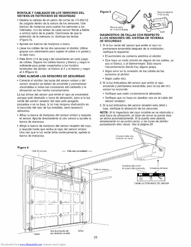
MONTAJE Y CABLEADO DE LOS SENSORES DELSISTEMA DE RETROCESO DE SEGURIDAD
• Deslice la cabeza de un perno de coche de 1/4-20xl/2de pulgada dentro de la ranura de los sensores. Usetuercas de mariposa para sujetar los sensores alasmensulas, con las lentes de cada sensor frente a frentea ambos lades de la puerta. Cerci6rese de que laextensi6n de la mensula no obstruya las lentes(Figura 5).
• Apriete las tuercas de mariposa a mano.
• Lleve los cables de los dos sensores al abridor. Utilicegrapas con aislamiento para sujetar el cable a la pared yal cielo raso.
• Pele 6mm (1/4 de pulg.) del aislamiento en cada juegode cables. Separe los cables blanco y blanco y negro Iosuficiente para poder conectaflos a los tornillosterminales del abridor: el blanco al 2 y el blanco y negroal 3 (Figura 6).
COMO ALINEAR LOS SENSORES DE SEGURIDAD
• Conecte el abridor; las luces del sensor emisory delsensor receptor se deben de encender y permanecerencendidas si todas las conexiones del cableado y laalineacion se hart hecho correctamente.
La luz a.mbar del sensor que emite el rayo se encenderaaunque este obstruido o fuera de alineaci6n, pero si la luzverde del sensor receptor del rayo esta. apagada,parpadea o se ve baja, (y no hay ninguna obstrucci6n enel recorrido del rayo de luz invisible), sera necesarioalinearlos.
• Afloje la tuerca de mariposa del sensor emisory reajusteel sensor. Apunte directamente al otto sensory apriete latuerca de mariposa.
• Afloje la tuerca de mariposa del sensor receptordel rayo,y reajuste hasta que reciba el rayo del sensor emisor.Una vez que la luz verde brine continuamente, apriete latuerca de mariposa.
Figura 5 Tuercade mariposa
Pernode coche --_
de 1/4-20xl/2 de pulg. _ "Lente
DIAGNOSTICO DE FALLAS CON RESPECTOA LOS SENSORES DEL SISTEMA DE REVERSADE SEGURIDAD
1. Si la luz verde del sensor que emite el rayo nopermanece encendida despues de la instalacion,verifique Io siguiente:
• El suministro de corriente electrica al abridor.
• Que haya un corto circuito en alguno de los cables, yasea el blanco, o el blanco/negro. Esto ocurrefrecuentemente donde hay alguna grapa.
• Algun error en la conexidn de los cables de lossensores al abridor.
• Algun cable roto.
2. Si la luz indicadora del sensor que emite el rayoenciende y permanece encendida, pero la luz del ottosensor no enciende:
• Verifique que esten correctamente alineados.
• Verifique que no haya un alambre roto en el cable delsensor receptor.
3. Si la luz indicadora del sensor receptor esta debil obaja, verifique la alineaci6n de los sensores.
NOTA: Si la trayectoria del rayo invisible se ve obstruida oesta fuera de alineacidn, al tratar de cerrar la puerta estase abrira automaticamente. Si la puerta esta abierta,simplemente no se podra cerrar, y las luces de abridorparpadearan diez veces. Vea la pagina 20.
Conecteel cablealasterminales del abridor
Figura 6Cable de campana
-- Cielo raso conacabado -- ..--*'"""÷'"'°""*''""
Conexionosdelcontrol
"---, j/-Cable de campana de la puerta (Nnea_punteada)Conexionesdel sensor
/
TORNILLOSTERMINALESDEL ABRIDOR
,_reade protecci6ndelrayo electr6nicoinvisible
//
Sensor
_Sensor
22
Downloaded from www.Manualslib.com manuals search engine

INSTALACION, PASO 1 1Fije la M6nsula de la Puerta
Siga las instrucciones que correspondan al tipo de puertade cochera que usted tenga, come se muestra en lailustracidn o en la pagina siguiente
Si usa un puntal horizontal, este debe set Iosuficientemente largo para sujetarlo a dos soportesverticales. Si usa un puntal vertical, este debe serde la altura del panel superior.
La ilustracidn muestra una pieza de hierro en angulo comepuntal horizontal Para el puntal vertical se deben usar dospiezas de hierro en angulo con objeto de crear un soporteen "U" (Figura 1) La mejor solucion es ponerse encontacto con la compaSfa fabricante de la puerta de sucochera e informarse acerca de los juegos de refuerzos depuertas para la instalacidn de un abridor
NOTA: Muchas de las instalaciones con soporte opuntal vertical toman en cuenta la instalaciSn directa de lospasadores de chaveta y el braze de la puerta En estecase, no necesitara instalar la mensula pare la puerta;proceda al Paso 12
PUERTAS SECClONALES
• Coloque la mensula para la puerta sobre la Ifnea centralvertical que habfa marcado previamente para lainstalacion de la mensula del cabezal Asegurese deque la leyenda "UP" (arriba) este en la posicidncorrecta, come esta indicado en la parte interior de lamensula (Figure 2)
• Coloque la mensula sobre la parte frontal de la puerta,dentro de los limites siguientes:
A) El borde superior de la mensula 5-10 cm (2-4 pulg)debajo del borde superior de la puerta
En el caso de puertas de fibra devidrio, aluminio o aceroligero, ES NECESARIOcolocar un refuerzo ANTESde instalarel marco de la puerta. P6ngaseen contacto con el fabricantedesu puerta para obtener un kit de refuerzo.
ESTAS PIEZAS SE MUESTRAN EN SU TAMAI_IO REAL
de pulg. Arandelade 5/16 de pulg.
Perno decache de5/16-18par 2-1/2de pulg.
B) La orilla superior de la mensula debe estardirectamente debajo de algun soporte de laestructura a Io largo de la parte superior de la puerta
• Marque y taladre dos orificios de 5/16 de pulg para lossujetadores ala derecha y ala izquierda Sujete lamensula al refuerzo vertical (si este existe), come semuestra en la Figura 1
Si el tipo de instalacion de su cochera no requiererefuerzos verticales, pero sf necesita los orificios paralos sujetadores de la mensula, taladre y fijelos come semuestra en la Figura 2
M_nsuladel cabezal
Ubicaci6nde
de la puerta
ineacentral
puerta de garaje
Si su puerta es de metal, aluminio,fibra de vidrio o con paneles de vidriosiempre son neeesarios refuerzosverticales y horizontales,(No ee ineluyen)
vertical de lapuerta de garaje
puerta odel refuerzo
Pernode cochede 5/16-18x2-1/2
de pulg.
Mensula de
Arandela de I
5/16 de pulg.Tuercade5/16-18de pulg.
ARRIBA
HACIAARRIE
Figura 1
M_neulade la puerta Figura 2
23
Downloaded from www.Manualslib.com manuals search engine
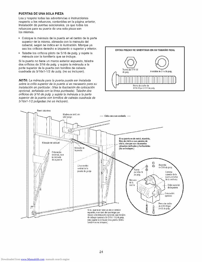
PUERTAS DE UNA SOLA PIEZA
Lea y respete todas las advertencias e instruccionesrespecto a los refuerzos, contenidas en la pa.gina anterior,Instalaci6n de puertas seccionales, ya que todos losrefuerzos para su puerta de una sola pieza sonlos mismos.
• Coloque la mensula de la puerta en el centro de la partesuperior de la misma, aNneada con la m6nsula delcabezal, segun se indica en la ilustraci6n. Marque yasea los orificios derecho e izquierdo o superior y inferior.
• Taladre los orificios piloto de 5/16 de pulg. y sujete lamensula con la tornNlerfa que se incluye.
Si la puerta no tiene un marco exterior expuesto, taladredos orificios de 3/16 de pulg. y sujete la mensula a laparte superior de la puerta con tornillos de cabezacuadrada de 5/16x1-1/2 de pulg. (no se incluyen).
NOTA: La mensula para la puerta puede ser instaladasobre la orilla superior de la puerta si es necesario para suinstalacidn en particular. (Vea la ilustracidn de colocacidnopcional, sefialada con la Ifnea punteada). Taladre dosorificios de 3/16 de pulg. y sujete la mensula a la partesuperior de la puerta con tomillos de cabeza cuadrada de5/16xl-1/2 pulgadas (no se incluyen).
ESTAS PIEZAS SE MUESTRAN EN SU TAMAI_IO REAL
Tuerca de 5/16-18de pulg. Arandelade 5/16 de pulg.
Pernode cache de5/16-18par 2-1/2 de pulg.
Pared delantera
Maderade 5x10 cm(2x4 pulg.)
-- Cielo raeo con aeabado --
M_nsuladel cabezal
Coloeacion
opcional,parala mensulade la puerta
M_nsulade
la puerta
Lfneacentral
puerta de garaje
Si su puertaes de metal, aluminio,
fibra de vidrio o con paneles,de
refuerzos vertiealesy horizontales(No ee incluyen.)
Si su puerta no tiene un marcoexteriorexpuesto,o en caso de que tenga querecurdra la instalaci6nopcional, usetornillosde cabezacuadrada de 5/16x1-1/2de pulg.para sujetar la mensula de la puerta (Estostornillos no se incluyen.)
Arandela
de 5/16de/_ pulg.
de 5/16-18 , Extreme
de pulg. ,.._ superiorde la_.4._ _"_.z puerta (interior
Mensula_ de la eoehera)de la f_puerta {_\ _ "_"_,_+,_o I Orilla superior
___,_ de la puerta-_/1,) ,._ ,_:7_:p,--/]) ," 714-i, Colocacion
_erno de cache
de 5/16-18pot
2-1/2de pulg.
24
Downloaded from www.Manualslib.com manuals search engine

INSTALACION, PASO 12Conecte el Brazo de la Puerta al Trole
Siga las instrucciones que correspondan al tipo de puertade cochera que usted tenga, come se muestraa continuacion y en la p_.gina siguiente.
SOLO PARA PUERTAS SECClONALES
• Cerciorese de que la puerta de la cochera estecompletamente cerrada. Tire de la manija de emergenciapara desconectar el trole exterior del trole interior.Deslice el trole exterior hacia atras (en direccion opuestaa la polea) per Io menos 20 cm (8 pulg.) come se indicaen las Figuras 1,2 y 3.
• Figura 1:
- Fije la secci6n recta del braze de la puerta al troleexterior usando un pasador de chaveta de 5/16xl pulg.Asegure la conexion con el anillo sujetador.
- Fije la seccidn curva del braze a la mensula dela puerta de la misma manera, con un pasador dechaveta de 5/16 per 1-1/4 de pulg.
• Figura 2:
- Junte las dos secciones del braze, Iocalizando dospares de orificios que se puedan alinear. Seleccionedos orificios que esten tan separados come seaposible para aumentar la rigidez del braze de lapuerta.
• Figura 3, Opciones para alinear los orificios:
- En case de que los orificios del braze curve no sepuedan alinear con los orificios del braze recto,desconecte el braze recto y corte aproximadamente15 cm (6 pulg.) del extreme que no tiene orificios.Vuelva a conectarlo al trole, con el extreme cortadohacia abajo, come se muestra.
- Junte las dos secciones de los brazes.
- Localice dos pares de orificios de ambas seccionesque se puedan alinear y Qnalos con tornillos,arandelas y tuercas.
• Tire de la manija de emergencia hacia el abridor enun angulo de 45 grades, de manera que el braze deliberaci6n del trole este en posicidn horizontal. Procedaa la seccion de Ajustes, Paso 1, en la pagina 27. El trolevolvera a estar listo automa.ticamente, cuando se opereel abridor.
Figura 1
Figura 2
Pasadorde chaveta
de 5/16x1-1/4de pulg.
Polea
_ /o menes20 cm k(8 putg.)
@,#
'x Pernosde@_. : 5/16-18x7/8
-_(&' de pulg,
M6nsulade la puerta
Polea
Lo menos20cr._i(8pulg.)
ESTAS PIEZAS SE MUESTRAN EN SU TAMAI_IO REAL
©Tuerca de
5/16-18de pulgada
5/16xl pulg. (para el trele)
Arandela de
5/16 de puigada
Anillo sujetador
o}Pasadordechavetade hexagonalde5/16xlqi4depulg. (para 5/16q8x7/8lam6neulade h puerta) de pulgada
Figura 3
" Pemosde5/16-18x7/8
de pulg,
Corte este extreme
25
Downloaded from www.Manualslib.com manuals search engine

TODAS LAS PUERTAS DE UNA SOLA PIEZA
1. Arme el brazo de la puerta, Figura 4:
• Sujete las dos secciones de los brazes de la puerta(recto y curve) a la mayor distancia posible, demanera que dos o tres de los orificios se sobreponganuno al otro.
• Cierre la puerta y fije la seccion recta del braze a lamensula de la puerta con el pasador de chaveta de5/16x1-1/4 de pulgada.
• Aseg0relos con un anillo sujetador.
2. Procedimiento de ajuste, Figura 5:
• Si tiene una puerta de una sola pieza, debera ajustarlos limites del recorrido antes de conectar el braze de
la puerta. Los tornillos de ajuste del Ifmite de recorridose encuentran en el panel del lade izquierdo, come semuestra en la ilustracion que aparece en la pagina 27.Siga el procedimiento de ajuste que aparece acontinuacion.
• Ajuste de la puerta al abrirla: Disminuya el limitedel recorrido HACIA ARRIBA
- Ajuste el tornillo para ajustar el Ifmite del recorridoHAClAARRIBA, dandole 4 vueltas hacia la izquierda.
- Oprima el bot6n de control de la puerta. El troledebera, ir hasta la posici6n completamente abierta.
- Abra la puerta manualmente de manera que esteparalela con el piso y suba el brazo de la puerta altrole. El brazo de la puerta debera tocar el trole justoen la parte posterior del orificio conector. Consulte lailustracion correspondiente al brazo de la puerta y altrole en su posici6n completamente abierta. Si elbraze no se extiende Io suficiente, ajuste el limite delrecorrido de la puerta; cada vuelta completa deltornillo equivale a 2 pulg. (5 cm) del recorrido deltrole.
• Ajuete de la puerta al cerrarla: Disminuya el limitedel recorrido HACIA ABAJO
- Ajuste el tomillo para ajustar el Ifmite del recorridoHAClAABAJO, dandole 4 vueltas completas hacia laderecha.
Figura 5Trole intemo
M6nsulade la puertaAnillo suietador
Pasadorde Brazo rectochavetade5/16x1-1/4de pulgada Pemos de
5/16-18x7/8
Figura 4 de pulgada
TuercadeArandelade 5/16-18
5/16 de pulgada pulgadas
Brazo curvo
- Oprima el bot6n de control de la puerta, el troledebera ir hasta la posicion completamente cerrada.
- Cierre la puerta manualmente y suba el brazo de lapuerta al trole. El brazo de la puerta debera tocar eltrole justo delante del orificio conector del braze de lapuerta. Consulte la ilustracion correspondiente albrazo de la puerta y al trole en su posici6ncompletamente cerrada. Si el braze queda detras delorificio conector, ajuste el Ifmite del recorrido de lapuerta; cada vuelta completa del tornillo equivale a2 pulg. (5 cm) de recorrido del trole.
3. Conecte el brazo de la puerta al trole:
• Cierre la puerta y sujete el braze curvo al orificioconector del trole con el t]ltimo pasador de chaveta.Es posible que necesite levantar un poco la puertamanualmente para poder hacer esta conexi6n.
• Asegure con un anillo sujetador.
• Opere el abridor durante un ciclo complete delrecorrido. Si la puerta parece estar en cierto a.ngulo(hacia atras) cuando esta completamente abierta,come se muestra en la siguiente ilustraci6n, disminuyael limite del recorrido hacia arriba hasta que la puertaquede paralela al piso.
NOTA: AI establecer el ffmite hacia arriba come se indica
en la pagina siguiente, la puerta no debe tener unainclinacidn "hacia atras" cuando este totalmente abierta,come se ilustra abajo. Una ligera inclinacidn hacia atrasocasionara que la puerta se pandee innecesariamente y/oque la operacidn no sea uniforme al abrir o cerrar la puertadesde la posicidn totalmente abierta.
extemo
Puertaabierta
/_,ngulocorrecto
Downloaded from www.Manualslib.com manuals search engine
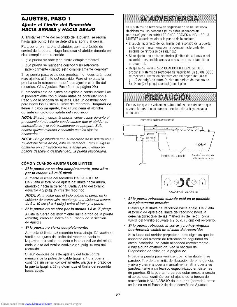
AJUSTES, PASO 1Ajuste el Limite del Recorrido
HACIA ARRIBA y HACIA ABAJO
AI ajustar el limite del recorrido de la puerta, se regulahasta que punto esta se detendra al abrir y al cerrar.
Para poner en marcha el abridor, oprima el boton decontrol de la puerta. Haga funcionar el abridor durante uncic!o complete de! recorrido.
• z,La puerta se abre y se cierra completamente?
• z,La puerta se mantiene cerrada y no retrocedeindebidamente cuando esta completamente cerrada?
Si su puerta pasa estas dos pruebas, no necesitar_t hacermas ajustes al limite del recorrido. Pero si no pasa laprueba de la retroceso, tendra que ajustar el limite delrecorrido. (Vea Ajustes, Paso 3, en la pagina 29.)
El procedimiento de ajuste se explica a continuacion: Leael procedimiento con cuidado antes de continuar con elPaso 2 de la seccion de Ajustes. Use un destornilladorpara hacer los ajustes al limite del recorrido. Despues deIlevar a cabo un ajuste, haga funcionar el abridordurante un ciclo completo del recorrido.
NOTA: El abrir y cerrar la puerta varias veces durante elprocedimiento de ajuste puede causar que el abrider sesobrecaliente y al sobrecalentarse se apagara. Sdloespere quince minutes y continue con los ajustesnecesarios.
NOTA: Si alge interfiere con el recorrido de la puerta en sutrayectoria hacia arriba, esta se detendra. Pore si algo laebstruye en su trayectoria hacia abajo (incluyendo unpesible desnivel e desbalanceo), la puerta retrecedera.
Si el sistema de retroceso de seguridad no se ha instaladodebidamente, las personas (y los nifios pequefios enparticular) podrian sufrir LESIONESGRAVESo INCLUS0 LAMUERTEcuando se cierra la puerta de la cochera.
• Elajuste incorrecto de los limites del recorrido de la puertade la cochera interferir_ con la operaciOnadecuadadelsistema de retroceso de seguridad.
• Si se ajusta uno de los controles (limites de la fuerza o delrecorrido), es posible que sea necesario ajustar tambi6n elotro control.
• Despu_sde Ilevar a cabo CUALQUIERajuste, SE DEBEprobar el sistema de retroceso de seguridad. Lapuerta DEBEretroceder al entrar en contacto con un objeto de3.8 cm(1-1/2 de pulg.) de altura (o bien un pedazo de madera de5x10 cm (2x4 pulg.) acostado) en el piso.
Paraevitar que los vehiculos sufran dafios, cerci6rese de quecuando la puerta est6 completamente abierta haya espaciosuficiente.
Pemo de la cubiertade protecci6nI
COMO Y CUANDO AJUSTAR LOS LIMITES
• Si la puerta no se abre completamente, pero abrepor Io menos 1.5 m (5 pies):
Aumente el limite del recorrido HACIA ARRIBA.De vuelta al tornillo de ajuste del limite hacia arriba,gir_tndolo hacia la derecha. Cada vuelta del tornilloequivale a 2 pulg. (5 cm) del recorrido.
NOTA: Para evitar que el trele gelpee el peme de lacubierta de proteccidn, mantenga una distancia mfnimade 5 a 10 cm (2 a 4 pulg.) entre el trele y el peme.
• Si la puerta no se abre por Io menos 1.5 m (5 pies):
Ajuste la fuerza del movimiento hacia arriba de la puerta(abierta), come se indica en el Paso 2 de la seccionde Ajustes.
• Si la puerta no cierra completamente:
Aumente el limite del recorrido hacia abajo. De vuelta altornillo de ajuste del limite del recorrido hacia laizquierda, (direcci6n opuesta alas manecillas del reloj);cada vuelta del tornillo equivale a 2 pulg. (5 cm) delrecorrido.
Si aOn despues de este ajuste y del trole contramensula de la polea del cable (pagina 4), la puertacontinua sin cerrar completamente, alargue el braze dela puerta (pagina 25) y disminuya el limite de! recorridohacia abajo.
OALOOMA[/iA DEAJUSTES
Si la puerta retrocede cuando esta en la posici6ncompletamente cerrada:
Disminuya el limite del recorrido hacia abajo. De vueltaa! tornillo de ajuste del limite del recorrido hacia laderecha (direcci6n de las manecillas del reloj); cadavuelta del tornillo equivale a 2 pulg. (5 cm) del recorrido.
Si la puerta retrocede al cerrar y no hay ningunainterferencia visible en el ciclo del recorrido:
Si la luces del abridor parpadean, esto significa que lossensores del sistema de retroceso de seguridad noestan instalados, no est_tn alineados correctamenteo hay alguna obstrucci6n. Vea la seccion deDiagnostico de fallas en la pagina 22.
Pruebe la puerta para verificar que no se doble ni sepandee. Tire de la manija de liberaci6n de emergencia,y abra y cierre la puerta manualmente. Si la puerta sepandea, Ilame a un tecnico especializado en sistemasde puertas. Si la puerta no parece estar desbalanceadani se pandea, continOe con el ajuste de la fuerza delmovimiento HACtAABAJO de la puerta (cerrada), comese indica en e! Paso 2 de de la secci6n de Ajustes.
27
Downloaded from www.Manualslib.com manuals search engine

AJUSTES, PASO 2Ajuste la Fuerza
Los controles para el ajuste de la fuerza del abridor seencuentran en el panel de posterior de la unidad delmotor. Estos ajustes controlaran la fuerza que serifnecesaria para abrir y cerrar la puerta.
Si la fuerza es muy debil, es posible que la puerta hagaesos molestos retrocesos al cerrarla (movimiento haciaabajo) y que se detenga al abrirla (movimiento haciaarriba). El clima puede afectar el movimiento de la puerta,asi que es posible que tenga que hacer algunos ajustesocasionalmente.
El maximo margen de ajuste de la fuerza es 3/4 de unavuelta, no trate de forzar el control mas alia de este
punto. Use un destornillador para hacer los ajustes.
NOTA: Si algo interfiere con el recorrido de la puerta en sutrayectoria hacia arriba, #sta se detendra. Pero si algo laobstruye en su trayectoria hacia abajo (incluyendo unposible desnivel o desbalanceo), esto activara la retrocesoy la puerta retrocedera.
Si el sistema de retroceso de seguridad no se ha instaladodebidamente, las personas (y los nifios pequefios enparticular) podrian sufrir LESIONESGRAVESo INCLUSOLAMUERTEcuando se cierra la puerta de la cochera.
• Si el limite de la fuerza de la puerta de la cochera es excesivointerferirA con la operaciOnadecuadadel sistema deretroceso de seguridad.
• NUNCAaumente la fuerza m_s all_ de la cantidad minimaque se requiera para cerrar la puerta de la cochera.
• NUNCAuse los ajustes de la fuerza para compensar si lapuerta de la cochera se pandea o se atora.
• Si se ajusta uno de los controles (limites de la fuerza o delrecorrido), es posible que sea necesario ajustar tambi@ elotro control.
• Despu@de Ilevar a cabo CUALQUIERajuste, SE DEBEprobar el sistema de retroceso de seguridad. Lapuerta DEBEretroceder al entrar en contacto con un objeto de3.8 cm(1-1/2 de pulg.) de altura (o bien un pedazo de madera de5x10 cm (2x4 pulg.) acostado) en el piso.
COMO Y CUANDO AJUSTAR LA FUERZADEL ABRIDOR
1. Pruebe la fuerza del recorrido HACIA ABAJO (cerrar)
• Sujete la puerta manualmente agarrandola per laparte inferior y detengala mas o menos a la mitad delrecorrido HACtA ABAJO (cerrar); la puerta deberaretroceder. Si la puerta retrocede a la mitad delrecorrido, esto no garantiza que la puerta retrocederaal toparse con una obstruccidn de 3.8 cm (1-1/2 depulg). Dirfjase al Paso 3 de la seccidn de Ajustes, enla pagina 29. Si es dificU sostener la puerta o biensi la puerta no retrocede, DISMtNUYA la fuerza delmovimiento HACIAABAJO (cerrar), con el control deajuste dandole vuelta hacia la izquierda. Hagapequefies ajustes hasta que la puerta retrocedacerrectamente. Despues de Ilevar a cabe un ajuste,haga funcionar e! abridor durante un cic!o completodel recerrido.
• Si la puerta retrocede automaticamente en latrayectoria hacia abajo (cerrar), y la luces delabridor no est_in parpadeando, AUMENTE la fuerzade la trayectoria HACIAABAJO (cerrar) con el controlde ajuste dandole vuelta hacia la derecha. Hagapequefies ajustes hasta que la puerta complete unciclo de cerrado. Despues de Ilevar a cabo el ajuste,haga funcionar el abrider durante un cicle completodel recerrido. No aumente la fuerza mas del mfnimonecesario para cerrar la puerta.
2. Pruebe la fuerza del recorrido HACIA ARRIBA (abrir)
• Sujete la puerta manualmente agarrandola per laparte inferior y detengala mas e menos a la mitad delrecerrido HACtA ARRIBA (abrir); la puerta deberadetenerse. Si la puerta no se detiene o es dificilsostenerla, DISMINUYA la fuerza de la puerta HACIAARRIBA con el control de ajuste, dandole vuelta haciala izquierda. Haga pequefies ajustes hasta que lapuerta pare f&cilmente y abra completamente.Despues de Ilevar a cabo cada ajuste, haga funcionare! abridor durante un cic!o completo de! recorrido.
Controbs para el ajustede la fuerzade la puerta
[] []i
CALCOMANiADEAJUSTES
La fuerza de abrir La fuerzade eerrar
• Si la puerta no se abre por Io menos 1.5 m(5 pies), AUMENTE la fuerza del RECORRIDOHACIA ARRIBA (abrir) con el control de ajuste,dandele vuelta hacia la derecha. Haga pequefiosajustes hasta que la puerta abra completamente.Reajuste el limite del recerrido HACIA ARRIBA si esnecesario. Despues de Ilevar a cabo cada ajuste,haga funcionar e! abridor durante un cic!o completodel recorrido.
28
Downloaded from www.Manualslib.com manuals search engine

AJUSTES, PASO 3Pruebe el Sistema de Retroceso de
Seguridad
PRUEBA
• Abra completamente la puerta, coloque un pedaze demadera de 3.8 cm (I-1/2 de pulg.) (o un pedazo demadera de 5x10 cm (2x4 pulg.) acostade sobre e! piso)en e! centre de la puerta de la cochera.
• Opere la puerta en la direccion hacia abajo. La puertadebera retroceder automaticamente a! hacer contactocon la obstruccion.
AJUSTE
• Si la puerta se detiene al toparse con la obstrucci6n,esto significa que el recorrido HACIAABAJO (cerrar) noes suficiente. Aumente el limite del recorrido HACIA
ABAJO, con el tornillo correspondiente, haciendolo girar1/4 de vuelta hacia la izquierda.
NOTA: Si su puerta es seccional, aseg#rese de que losajustes al Ifmite no hagan que el brazo de la puerta semueva mas alia de una posicidn recta hacia arriba yhacia abajo. Vea la ilustracidn en la pagina 25.
• Repita la prueba.
• Si la puerta retrocede automaticamente al hacercontacto con el pedazo de madera de 3.8 cm(1-1/2 de pulg.), quite la obstrucci6n y abra y cierre lapuerta completamente per Io menos tres o cuatro vecespara verificar que el ajuste sea adecuado.
• Si la unidad sigue fallando la prueba del sistema dereversa de seguridad, Ilame a un tecnico en sistemas depuertas.
VERIFICAClON IMPORTANTE DE SEGURIDAD:
Compruebe e! sistema de reversa de seguridad despuesde que:
• Se hagan ajustes al largo del braze de la puerta, loslimites del recorrido, o los controles de la fuerza.
• Se hagan reparaciones o ajustes a la puerta de lacochera (incluyendo los resortes y la tornilleria).
• Se hagan reparaciones a! piso de la cochera porqueeste desnivelado, etc.
• Se hagan reparaciones o ajustes al abridor.
AJUSTES, PASO 4Pruebe La Sistema de Protecci6n ®
• Oprima el bot6n de la unidad de control remote paraabrir la puerta.
• Coloque la caja de cart6n del abridor en la trayectoriade la puerta.
• Oprima de nuevo el bot6n de la unidad de controlremoto para cerrar la puerta; esta no se debera movermas de 2.5 cm (1 pulg.) y las luces del abridorempezaran a parpadear.
La puerta no se podra cerrar con ninguno de los controlesremotos si las luces indicadoras de cualquiera de lossensores est&n apagadas (indicandole que los sensoresestan fuera de alineaci6n, o que existe alguna obstruccion).
Si el abridor cierra la puerta cuando el sensor delsistema de retroceso de seguridad esta obstruido (y lossensores no estan a mas de 15 cm (6 pulg.) del piso),Ilame a un tecnico especializado en sistemas de puertas.
29
Si el sistema de retroceso de seguridad no se ha instaladodebidamente, las personas (y los nifios pequefios enparticular) podrian sufrir LESIONESGRAVESo INCLUSOLA MUERTEcuando se cierra la puerta de la cochera.
• Elsistema de retroceso de seguridad SE DEBEprobarcada rues.
• Si se ajusta uno de los controles (limites de la fuerza o delrecorrido), es posible que sea necesario ajustar tambi_n elotro control.
• Despu6sde Ilevar a cabo CUALQUIERajuste, SE DEBEprobar el sistema de retroceso de seguridad. La puerta DEBEretroceder al entrar en contacto con un objeto de 3.8 cm(1-1/2 de pulg) dealtura (o bien un pedazode maderade5x10 cm (2x4 pulg.) acostado) en el piso.
(2x4 pulg.) acostadosobre el piso)
Si el sensor de retroceso de seguridad no se ha instaladodebidamente, las personas (y los nifios pequefios enparticular) podrian sufrir LESIONESGRAVESo INCLUSOLA MUERTEcuando se cierra la puerta de la cochera.
@
Sensor del sistema de
retrocesode seguridadSensordel sistemade
retrocesode seguridad
Downloaded from www.Manualslib.com manuals search engine

OPERACION
INSTRUCCIONES IMPORTANTES DE SEGURIDAD
Para reducir el riesgo de LESIONES GRAVESo la MUERTE:
1. LEAYSIGATODASLASADVERTENCIASY LAS 9. Siajustaunodelos controles(limitesdela fuerzao delINSTRUCCIONESDEOPERACION. recorrido),es posiblequeseanecesarioajustartambiOnel
2. SIEMPREconserve los controles remotos fuera del alcance
de los nifios. NUNCApermita que los nifios operen o jueguencoo los botones del control de la puerta de la cochera ni conlos controles remotos.
3. SOLOactive la puerta de la cochera siempre y cuando lapuedaver con claridad, est_ debidamente ajustada y no hayanioguna obstrucciOn en el recorrido de la puerta al cerrarse.
4. SlEMPREtenga la puerta de la cochera a la vista hasta queest_completamente cerrada.NADIEDEBEATRAVESARELREOORRIDODE LA PUERTACUANDOESTAENMOVIMIENTO.
5. NADIEDEBEPASARPORDEBAJODE LA PUERTASI EST',DETENIDAY PARCIALMENTEABIERTA.
6. De ser posible, use la liberaciOode emergencia para soltar eltrole SOLOcuaodo la puerta de la cocbera est_ CERRADA.Silos resortes est_.nd_biles o rotos, o bieo si la puerta est,,desbalanceada,puede que la puerta se caiga r_,piday/oinesperadamentecuando est6 abierta.
7. NUNCAuse la manija de liberaciOnde emergeocia a menosque la entrada a la cochera est_ libre de obstrucciones y nohaya ninguna personapresente.
8. NUNCAuse la manija para tirar de la puerta para abrirla ocerrarla.Si el nudo de la cuerdase suelta, usted podria caerse.
otro control.
10. Despu_s de Ilevar a cabo CUALQUIERajuste, SE DEBEprobar el sistema de retroceso de seguridad.
11. El sistema de retroceso de seguridad SE DEBEprobar cadarues. La puerta DEBEretroceder al entrar en contacto conun objeto de 3.8 cm (1-1/2 de pulg.) de altura (o bien unpedazo de madera de5x10 cm (2x4 pulg.) acostado) en elpiso.
12. SIEMPREMANTENGALA PUERTADELA COCHERADEBIDAMENTEBALANCEADA(vea la p_gina 3). Si la puertano est_ debidamente balanceadapodria no retrocedercuaodo se requiera, Io que podria ocasiooar una LESIONGRAVEo INCLUSOLA MUERTE.
13. Todaslas reparaciones necesarias eo los cables, resortes yotras piezas las DEBEIlevar a cabo un t_cnico especializadoen sistemas de puertas, pues todas estas piezasest_.nbajounatension EXTREMA.
14. SIEMPREdesconecteel suministro de energia elOctricaalabridor de la puerta de la cochera ANTES de Ilevar a cabocualquier reparaciOno de quitar las cubiertas.
CONSERVEESTASINSTRUCCIONES.
C6mo Usar su Abridor de Puerta deCochera
Su abridor Security'! "_ y el control remoto manual han sidoprogramados en la fabrica con un c6digo coincidente quecambia cada vez que se usa, accesando al azar mas de100,000 millones de c6digos nuevos. Su abridor funcionarahasta con 8 controles remotos Security'k _ y un sistema deentrada sin Ilave Security'k _. Si compra un control remotonuevo, o si desea desactivar algOn control remoto, siga lasinstrucciones que aparecen en la secciOn sobre Comoprogramar el abridor.
Active su abridor de alguna de las siguientes maneras:
• El Control remoto manual: Mantenga oprimido el botOngrande hasta que la puerta se empiece a mover.
• El Control de pared de la puerta: Mantenga oprimido e!boton hasta que la puerta se empiece a mover.
• La Entrada sin Ilave (Vea Accesorios): Si su abridor depuerta de cochera viene con este accesorio, deberaestar programado antes de usarlo. Vea Como programarel abridor.
Una vez activado el abridor (con el sensor de seguridad deretroceso correctamente instalado y alineado)
1. Si la puerta esta abierta se va a cerrar. Si la puerta estacerrada se va a abrir.
2. Si la puerta se esta cerrando va a retroceder.
3. Si la puerta se esta abriendo se va a detener.
4. Si la puerta se ha detenido en un punto parcialmenteabierta, se va a cerrar.
5. Sial cerrarse la puerta se topo con alguna obstruccion,va a retroceder. Si la obstruccion interrumpe el rayo delsensor, las luces del abridor van a parpadear durantecinco segundos.
6. Sial abrirse la puerta se topo con alguna obstruccion,se va a detener.
7. Si la puerta esta completamente abierta, no va a cerrarsi el rayo esta interrumpido. El sensor no tiene ningOnefecto en el ciclo de apertura.
Si el sensor no se ha instalado o esta desalineado, lapuerta no se cerrara con el control remoto manual. Sinembargo, la puerta se puede cerrar con el Control de lapuerta, el lnterruptor de Ilave externo, o la Entrada sinIlave, siempre y cuando los active hasta que el recorridohacia abajo haya terminado. Si los suelta demasiadopronto, la puerta va a retroceder&
Las luces del abridor se encender_tn en los siguientescasos: Siempre que conecte el abridor inicialmente;cuando se restaura el suministro de energia despues deuna interrupcion; cuando el abridor se activa.
Las luces se apagan automa.ticamente despues de 4minutos y 1/2. Los bombillos deben ser de 75 vatiosmaximo.
30
Downloaded from www.Manualslib.com manuals search engine

Cdmo Usar la Unidad de Controlde Pared
Oprima el bot6n iluminado para abrir o cerrar lapuerta. Oprima de nuevo para que la puertaretroceda en el ciclo de cierre o para detener lapuerta cuando se esta abriendo.
Cdmo Abrir la Puerta Manualmente
Paraevitar la posibilidad de una LESIONGRAVEo INCLUSOLA MUERTEsi la puerta de la cochera se cae:
• Deser posible, use la manija de liberaciOnde emergenciapara soltar el trole SOLOcuando la puerta de la cochera est6CERRADA.Si los resortes est_n d_biles o rotos, o bien si lapuerta estAdesbalanceada,la puerta abierta podria caerser_,piday/o ioesperadamente.
• NUNOAuse la manija de liberaciOnde emergencia a menosque la entrada a la cochera est_ libre de obstrucciones y nohaya nioguna personapreseote.
• NUNCAuse la manija para tirar de la puerta para abrirlacerrarla. Si el nudo de la cuerda se suelta, usted podriacaerse.
COMO DESCONECTAR EL TROLE:
La puerta debe estar Trolecompletamente cerrada si esposible. Tire de la manija deliberacion de emergencia (demanera que el brazo deliberacion del trole quede en arazode__ "',una posicidn vertical) y levante liberaci6nla puerta manualmente. (en la posici6n
de desconexi6nLa funcidn de seguro evita que manual)el trole se vuelva a conectar |automa.ticamente, y la puertapueda subirse y bajarsemanualmente con la Posici6ncon el segurofrecuencia que sea necesaria. (desconexi6n manual)
COMO RECONECTAR EL TROLE:
Tire de la manija de liberaci6nde emergencia hacia elabridor en un angulo que elbrazo de liberacion del trole
quede horizontal. El trole sereconecta en la siguienteoperaci6n HAClAARRIBA oHAClAABAJO, ya seamanual o mediante el uso del
control de la puerta o delcontrol remoto.
Trole
_ Brazode
Manijade -._.liberacidnde "%-emergencia _ "_..(por debajoy pot det_,.f_'
Para reconectar
31
Downloaded from www.Manualslib.com manuals search engine

MANTENIMIENTO DE SUABRIDOR DE PUERTA DECOCHERA
AJUSTES DE L|MITE Y FUERZA:
Las condicionesCONTROLES DE FUERZA
climatol6gicas puedenocasionar cambios menoresen la operacion de la puerta,los cuales van a requeriralgunos reajustes,en particular durante el primerafio de operacion. CONTROLESDEL|MITE
En las p_.ginas 27 y 28 se
encuentra la informaci6n _ (_)_L@ _/_sobre los ajustes de Ifmite yde fuerza. Lo On|co quenecesita es un destornillador. Siga las instrucciones concuidado.
Repita la prueba de retroceso de seguridad (Ajustes,Paso 3, Pagina 29) despues de hacer ajustes a loslimites o la fuerza.
CALENDARIO DE MANTENIMIENTO
Una vez al rues
• Haga funcionar la puerta manualmente Si estadesbalanceada o se pan(lea, Ilame a un tecnicoespecializado en sistemas de puertas
• Revise para cerciorarse de que la puerta se abra y secierre completamente Ajuste los Ifmites y/o la fuerza deser necesario (Vea las paginas 27 y 28)
• Repita la prueba de la retroceso de seguridad Haga losajustes necesarios (Yea Ajustes, Paso 3)
Dos veces al a_o
• Verifique la tensi6n de la cadena Primero desconecte eltrole y ajustelo si es necesario (Vea la pagina 11)
Una vez al a_o
• Ponga aceite en los rodillos, los cojinetes y las bisagrasde la puerta El abridor no necesita lubricaci6n adicionalNo lubrique los carriles de la puerta
LA BATERiA DEL CONTROL REMOTO
Paraevitar la posibilidad de LESIONESGRAVESo INCLUSOLA MUERTE:
• NUNCApermita que los niios pequeios est6n cerca delas hater|as.
• Si alguien se traga una bateria, Ilame al m6dico deinmediato.
La baterfa de litio debe producirenergfa durante cinco aFios. Para Abraeste extremo
prirneroparacambiar la baterfa use el clip del evltarque / (_ -"'2allvisor o un destornillador para abrir lacaja.. _ ._.,_/se/_C_._._-"--AS/ila caja, come se indica en la agrle__/ilustracion. Inserte la baterfa deacuerdo con las instrucci6nes de
polar|dad indicadas en el cubiertodel control o en el tablero electron|co.
Deseche las baterfas viejas de la manera adecuada.
AVISO: Para cuml)lir con las reglas de la FCC y/e de Canada (IC), ajustes e modificaciones de este
recel)tor y/o emisor est£n prohibidos, excel)to pot el carnbio de la graduacion del cSdigo o el
reeml)lazo de la l)ila. NO HAY OTRAS PIEZAS REPARABLES DEL USUARIO.
Se ha probado l)ara curnl)lir con las normas de la FCC para USO DEL HOGAR 0 DE LA OFICINA.La ol)eraci6n est£ sujeta a las dos condiciones siguientes:(1) este disl)ositivo no l)uede causarinterferencia l)erjudicial, y (2) este dispositivo debe aceptar cualquier interferencia recibida,
nc uyendo a nter erenc a que puede causar una operac on no deseab e.
32
Downloaded from www.Manualslib.com manuals search engine
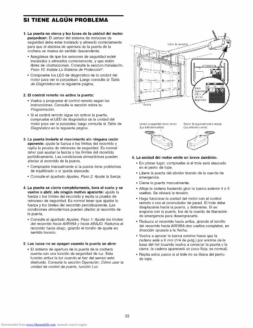
SI TIENE ALGON PROBLEMA
1. La puerta no cierra y las luces de la unidad del motorparpadean: El sensor del sistema de retroceso deseguridad debe estar instalado y alineado correctamentepara que el sistema de apertura de la puerta de lacochera se mueva en sentido descendente.
• AsegQrese de que los sensores de seguridad esteninstalados y alineados correctamente, y que estenIibres de obstrucciones. Consulte la seccion Instalaci6n,Paso 10: Instale La Sistema de ProtecciSn ®.
• Compruebe los LED de diagn6stico de la unidad delmotor para ver si parpadean. Luego consulte la Tablade Diagndstico en la siguiente pagina.
2. El control remoto no activa la puerta:
• Vuelva a programar el control remote segt]n lasinstrucciones. Consulte la seccion sobre su
ProgramaciSn.
• Si el control remote sigue sin activar la puerta,compruebe el LED de diagn6stico de la unidad delmotor para ver si parpadea; luego consulte la Tabla deDiagndstico en la siguiente pagina.
3. La puerta invierte el movimiento sin ninguna razonaparente: ajuste la fuerza o los Ifmites del recorrido yrepita la prueba de retroceso de seguridad. Es normaltener que ajustar la fuerza y los Ifmites del recorridoperi6dicamente. Las condiciones atmosfericas puedenafectar al recorrido de la puerta.
• Compruebe manualmente si la puerta tiene problemasde equilibrado o si queda atascada.
• Consulte el apartado Ajustes, Paso 2: Ajuste la fuerza.
4. La puerta se cierra completamente, toca el euelo y sevuelve a abrir, sin ningt_n motivo aparente: ajuste lafuerza o los Ifmites del recorrido y repita la prueba deretroceso de seguridad. Es normal tener que ajustar lafuerza y los I[mites del recorrido peri6dicamente. Lascondiciones atmosfericas pueden afectar al recorrido dela puerta.
• Consulte el apartado Ajustes, Paso 1: Ajuste los ffmitesdel recorrido hacia ARRIBA y hacia ABAJO. Reduzca elrecorrido hacia abajo, girando el tornillo de ajuste ensentido horario.
5. Lae luces no ee apagan cuando la puerta se abre:
• El sistema de apertura de la puerta de la cocheracuenta con una funci6n de seguridad de luz. Estafunci6n activa la luz cuando el haz del sensor esta
obstruido. Consulte la seccion Operacion; Cdmo usar launidad de control de puerta, funciSn Luz.
_ensor
Sensor de seguirdadsensor emisor Sensor de seguirdadsensor recepto(Luz indieadora g_mbar) (Luz indicadora verde)
\
6. La unidad del motor emite un breve zumbido:
• En primer lugar, compruebe si el trole esta atascadoen el perno de tope.
• Libere la puerta del abridor tirando de la cuerda deemergencia.
• Cierre la puerta manualmente.
• Afloje la cadena haciendo girar la tuerca exterior 4 6 5vueltas. Se aliviara la tensi6n.
• Haga funcionar la unidad del motor con el controlremote o con el conmutador de pared. El trole debedesplazarse hacia la puerta, y detenerse. Si seengrana con la puerta, tire de la cuerda de liberacionde emergencia para desengranarlo.
• Reduzca el recorrido hacia arriba, girando el tornillodel recorrido hacia ARRIBA dos vueltas completas, endirecci6n opuesta a la fiecha.
• Vuelva a apretar la tuerca exterior hasta que lacadena este a 6 mm (1/4 de pulg.) per encima de labase del riel (cuando vuelva a conectar la puerta y lacierre, la cadena aparecera un poco floja; es normal).
• Repita estos pasos si el trole no se libera del pernode tope.
33
Downloaded from www.Manualslib.com manuals search engine

Tabla de Diagn6stico
El circuito de los sensores
de seguridad esta abierto(cable roto o desconectado).
0 BIEN
Hay un cortocircuito en elcable de los sensores deseguridad, o los cablesblanco y negro estaninvertidos.
El control de la puerta o elcable tienen uncortocircuito.
Los sensores de seguridadestan ligeramente malalineados (LED debil oparpadeante).
El motor se calienta o hayun posible fallo de RPM.Desconectelo parareiniciarlo.
[.tl _ ,_f : !_ ,_l J] =[*I-lt ..............
Falla el circuito impresodel motor. Cambie el circuito
impreso del receptor.
El sistema de apertura de la puerta cuenta con una funcidn deautodiagndstico. El botdn "Aprender"/LED de diagndsticoparpadeara varias veces antes de detenerse, indicando que haencontrado un posible problema. Consulte la tabla de diagndsticoa centinuacidn.
,._ Sintoma: Una o ambas luces indicadoras de los sensores de seguridad nopermanecen encendidas.
• Inspeccione los cables de los sensores para determinar si presentan un cortocircuito(grapa en el cable), corrija la polaridad de los cables (cables blanco y negro invertidos),cables rotos o desconectados, sustituir/conectar segt]n proceda.
• Desconecte todos los cables en el dorso de la unidad del motor.
• Quite los sensores de sus soportes y acorte sus cables a 30-60 cm (1-2 pies) desde laparte posterior de cada sensor.
• Vuelva a conectar la celula transmisora con la unidad del motor, utilizando los cablescortos. Si la luz indicadora de la celula transmisora permanece encendida, conecte lacelula receptora.
• Alinee los sensores. Si las luces indicadoras se encienden, sustituya los cables de lossensores. Si las luces de los sensores no se encienden, sustituya los sensores deseguridad.
"'_ Sfntoma: El LED del control de la puerta no se enciende.
• Inspeccione la unidad de control de la puerta/cable para ver si tienen un cortocircuito(grapa clavada en el cable) y sustituya Io que proceda.
• Desconecte los cables de la unidad de control de la puerta y haga puente con loscables. Si la unidad del motor se activa, sustituya la unidad de control.
• Si el motor no se activa, desconecte del motor los cables de control de la puerta. Conun cable, haga puente entre los terminales rojo y blanco. Si el motor se activa, cambielos cables de control de la puerta.
.._ Sfntoma: La luz indicadora de la celula transmisora permanece encendida; la luzde la celula receptora es debil o parpadea.
• Vuelva a alinear la celula del sensor del receptor, limpie la lente y asegure el soporte.
• Asegt]rese de que el riel de la puerta este fijado firmemente a la pared y que no semueva.
Sfntoma: El motor esta muy caliente; El motor no funciona correctamente o el trole.._ esta atascado en el perno de tope = El motor emite un breve zumbido; Sensor de
RPM = Recorrido corto 15-20 cm (6-8 pulg.).
• Desconecte la unidad para reiniciarla. Intente hacer funcionar el motor, compruebe elc6digo de diagn6stico.
• Si sigue parpadeando 5 veces y el motor se mueve 15-20 cm (6-8 pulg.), cambie elsensor de RPM.
• Si el motor no funciona, significa que esta muy caliente. Deje pasar 30 minutos yvuelva a intentarlo. Si el motor sigue sin funcionar, cambie el circuito impreso.
.._ Sfntoma: El motor no funciona.
• Cambie el circuito impreso ya que es raro que falle el motor.
34
Downloaded from www.Manualslib.com manuals search engine

COMO PROGRAMAR EL ABRIDOR
AVI$O: Si utiliza este abre puertas de garaje Security÷ _ con un transmisor no dorado de un sistema de cddigos de salto(cddigo aleatorio), se veran circunvenidas las medidas t#cnicas incorporadas en el receptor del abridor para proteger contralos aparatos de captura de cddigos. El propietario de los derechos propiedad intelectual del abridor no autoriza ni alcomprador ni al proveedor de un transmisor no dorado de un sistema de cddigos de salto (cddigo aleatorio) a circunvenirdichas medidas t#cnicas.
Su abridor de puerta de cochera ya viene programado de fabrica para operar con su control remoto manual. La puerta seabrira y se cerrara cuando oprima el boton grande.
A continuaci6n se proveen las instrucciones para programar su abridor para que opere con controles remotosSecurity÷ ®adicionales.
C6mo Agregar o Reprogramar un Control Remoto Manual
COMO USAR EL BOTON LEARN (APRENDER)
Para Borrar Todos los C6digos de laMemoria de la Unidad del Motor
Para desactivar cualquier controlremote que no desee usar, antes quenada borre todos los c6digos:
Optima y mantenga oprimido el bot6n"Aprender" de la unidad del motor,hasta que la luz del indicador de Aprender se apague(aproximadamente 6 segundos). Ya estaran borradostodos los c6digos anteriores. Vuelva a programar cadauno de los controles remotos o la entrada sin Ilave quedesee usar.
1. Oprima y suelte el bot6n "Aprender"de la unidad del motor. La luzindicadora de este bot6n estara
encendida por 30 segundos.
2. En los 30 segundos, oprima ymantenga oprimido el bot6n delcontrol remoto manual* que deseeusar para su puerta de cochera.
3. Suelte el bot6n cuando las luces de
la unidad del motor empiecen aparpadear. Ya aprendio el c6digo.Si no se han puesto bombillos, seescuchara.n dos chasquidos.
/
*Controles Remotos de 3 Funciones
Si es provisto con su abridor de puerta de la cochera, elboton grande ha sido programado en la fa.brica paraoperacion de su abridor. Los botones adicionales decualquier control remotode funciones mt]ltiplesSecurity÷ ®o de unminicontrol remotopueden programarse paraoperar otros abridores de3uerta de cocheraSecurity÷ ®.
35
Downloaded from www.Manualslib.com manuals search engine

C6mo Agregar, Reprogramar o Cambiar un C6digo de Entrada sin Llave
NOTA: Su nueva Entrada sin Ilave debe programarse para que opere el abridor de la puerta de su cochera.
C6MO USAR EL BOTON LEARN (APRENDER)
Para cambiar un PIN existente
Si el PIN existente ya es conocido, una persona Io puedecambiar sin usar una escalera.
1. Oprima los cuatro botones que correspondan al PINactual, luego oprima y mantenga oprimido el boton #.
La luz del abridor parpadeara dos veces. Suelte elboton #.
2. Oprima el nuevo PIN de cuatro dfgitos y luego oprimaENTER.
1. Oprima y suelte el bot6n "Aprender"de la unidad del motor. La luzindicadora de este boton estaraencendida per 30 segundos.
2. En los 30 segundos, introduzca unnt]mero de identificaci6n personal(PIN) que haya elegido, usando elteclado. Luego oprima y mantengaoprimido el bot6n ENTER.
3. Suelte el bot6n cuando las luces dela unidad del motor empiecen aparpadear. Ya aprendio el c6digo. Sino ha instalado bombillos, seescucharan dos chasquidos.
ii /
Las luces de la unidad del motor parpadearan una vezcuando el PIN se haya aprendido.
Pruebe oprimiendo el nuevo PIN, luego oprima ENTER.La puerta debe moverse.
Para porter un PIN temporal
Usted puede autorizar el acceso a sus visitas o a personalde servicio con un PIN temporal de cuatro digitos.Despues de un determinado nt]mero de horasprogramadas, o nOmero de accesos, este PIN temporalexpira y no vuelve a abrir la puerta. Se puede usar paracerrar la puerta aOn despues de que haya expirado. HagaIo siguiente para poner un PIN temporal:
1. Oprima los cuatro botones correspondientes a su PINde entrada personal (no el Oltimo PIN temporal); luegooprima y mantenga oprimido el bot6n _.
La luz del abridor va a parpadear tres veces. Suelte elboton.
2. Oprima los cuatro d/gitos del PIN temporal que hayaelegido, luego oprima ENTER.
La luz del abridor va a parpadeara cuatro veces.
3. Para fijar el nt]mero de horas que el PIN temporal debefuncionar, oprima el nOmero de horas (hasta 255), luegooprima _.
O
3. Para fijar el numero de veces que el PIN temporal debefuncionar, oprima el nOmero de veces (hasta 255), luegooprima #.
La luz del abridor parpadeara una vez cuando el PINtemporal haya sido aprendido.
Pruebe oprimiendo los cuatro botones correspondientes alPIN temporal, luego oprima ENTER. La puerta debemoverse. Si el PIN temporal se ha fijado para abrir lapuerta un determinado nOmero de veces, recuerde que laprueba constituye una vez. Para borrar la contrase_atemporal, repita los pasos del 1 al 3; fijando el nt]mero dehoras o de veces en 0, en el paso 3.
36
Downloaded from www.Manualslib.com manuals search engine

ACCESORIOS
139.53702
fLiberador de la Ilave de emergencia:
Se requiere en las cocheras que NOtienen puerta de acceso. Permite alduefio de la casa abrir la puerta de lacochera manualmente desde el exterior,desconectando el trole.
139.53726 Extension del riel de 2.4 m (8 pies):
Permite que una puerta de 2.4 m(8 pies) se abra completamente.
139.53727 Extension del riel de 3 m (10 pies):
Permite que una puerta de 3 m (10 pies)se abra completamente.
139.53589
41A5281
139.53709
M_nsulas de soporte:
Para cielos rasos sin acabados o en loscases en que se necesite soporteadicional, basado en la construcci6n dela cochera. Incluye las mensulas y lossujetadores.
Mensulas de extension:(Solo estan disponibles a traves deRefacciones y Servicio Sears)
(Opcionales) Para la instalacion delsensor de seguridad en la pared o en elpiso.
Mensulas para la altura de la puerta: (Solopara puertas seccionales)
Sustituyen a las mensulas superiores y losrodillos de la puerta para reducir la altura delrecorrido de la puerta. Para usarse cuandose instala el abridor en una cochera con pocatolerancia (altura).
139.53753
139.53752
139.53754
139.53687
139.53749
SECURITY÷ ®Control remoto de3 funciones:
Incluye el clip del visor.
SECURITY+++®Control remoto compactode 3 funciones:
Con lazada para ponerse en el Ilavero.
SECURITY÷ ®Entrada sin Ilave:
Permite al duefio de la casa operar lapuerta de la cochera desde el exterior,ingresando una contrasefia. Tambienpuede agregarse una contrasefia temporalpara visitas o personal de servicio.
Consola de control premium:
Cuenta con una funci6n de seguro paraevitar que la puerta de la cochera funcionedesde controles remotos port&tiles. Cuentatambien con una funci6n de luz quecontrola las luces del abridor. Se puedeusar para programar el abridor paraaceptar controles remotos adicionales.
Control de luz enchufable:
Permite al duefio de la casa encender unaI&mpara, la televisi6n, u otro aparatodomestico con el control remote desde el
coche, la cama, o dondequiera que seencuentre en la casa.
GARANTiA
GARANTiA SEARSEL ABRIDOR DE PUERTA DE COCHERA TIENE UNA GARANTIA COMPLETA DE ANO
Duranteafio a partir de la fecha decompra,Searshara las reparacionesdesu Abridorde puertade cocherasin costopara ustedsi el abridortienedefectosen materialeso manode obra.
GARANTiA LIMITADADELMOTORMotorde 1/2 caballode fuerza: Despues del primer afio y hasta un plazo de4 aflos, si el rnotordelAbridor de puerta de cocheraestadefectuoso, Sears proporcionaraunmotorde repuesto, sin costo alguno. Ustedpaga la manodeobra.
LIMITE DELA RESPONSABILIDADSEARSNOSERA RESPONSABLEPORt.ASPC:RDIDAS O DAI_IOS QUESUFRALAPROPIEDAD, NIPORPI_RDIDAS OGASTOSINClDENTALESOCONSECUENTESDERIVADOSDEDAI_IOSALAPROPIEDADQUEPUDIERANDIRECTAOINDIRECTAMENTESERELRESULTADODELUSARESTEPRODUCTO.Enalgunos estadosnoest_permitido laexdusi6no limitede losdafiosincidentalesoconsecuentes,demaneraqueel limiteoexclusi6narfibacitado puedeno aplicarensucaso.Esta garantianocubrefocosnipiezas de repuesto necesariascuandoesteproducto se ha tratadoindebidamenteocon negligencia, incluyendonoIlevara cabola instalaci6n, ajuste y operaci6n deesteabridordepuerta decocheradeacuerdoa lasinstruccionescontenidasen el instructivodelpropietario.
ELSERVICIODEGARANTiAEST', DISPONIBLECON PONERSEENCONTACTOCON ELCENTRODESERVICIOSEARSM,_SCERCANOENLOSESTADOSUNIDOS.Esta garantia aplica solamentemientrasesteproducto se este usandoen los EstadosUnidos.Esta garantia le otorga derechos legales especificos, y usted podrfa tenerotros derechosque pueden ser diferentesencada estado.
Sears, Roebuck and Co., Dept. 817WA, Hoffman Estates, IL 60179
37
Downloaded from www.Manualslib.com manuals search engine
Your HomeFor repair-in your home-of all major brand appliances
lawn and garden equipment, or heating and cooling systems,no matter who made it, no matter who sold it!
For,the replacement parts accessories andowner s manuals that you need to do-it-yourself.
For Sears professional installation of home appliancesand items like garage door openers and water heaters.
1-800-4-MY-HOME ® (1-800-469-4663)Ca II anytim e, day or n ight (U. S .A. and Ca nada )
www.sears.com www.sears.ca
Our Homeiiiiiiiiiiiiiiiiii
For repair of carry-in items like vacuums, lawn equipment,
and electronics, call or go on-line for the location of your nearest
iiiiiiii Sears a,ts.e airCenter,1-8oo-488-1222
iiiiiiii o,ohtIo.s. .oo, 1www.soars.com
To purchase a protection agreement (U.S.A.)or maintenance agreement (Canada) on a product serviced by Sears:
1-800-827-6655 (U.S.A.) 1-800-361-6665 (Canada)
Pard pedir servicio de reparaciCn Au Canada pour serv ce en fran(_a s
a domicilio, y pard ordenar piezas' 1 LE F YER Mc• -800- - 01-888-S U- HOGAR SM (1-800-533-6937)
(1-888-784-6427) www.sears.ca
114A3125B
® Registered Trademark / TMTrademark / s_ Service Mark of Sears, Roebuck and Co.® Marca Registrada / TMMarca de Fabrica / sMMarca de Servicio de Sears, Roebuck and Co.McMarque de commerce / MDMarque deposed de Sears Roebuck and Co.
© 2005 Sears, Roebuck and Co.Printed in Mexico
Downloaded from www.Manualslib.com manuals search engine