Embed Size (px)
Citation preview

1
The Carrier 42JW fan coil units offer reliable, economical cooling and heating for light and medium commercial and residential applications.
They are available in three sizes with cooling capacities from 3.00 to 16.0 kW, heating capacities from 4.2 to 18.5 kW, and air flows from 180 to 690 l/s.
Features
n
The cabinet is made of aluminium zinc or pre-painted gal-vanised steel. All sizes include thermal and acoustic insula-tion, a sloped condensate drain pan with external anti-con-densate insulation, and a drain.
n
The high-efficiency water-to-air heat exchangers are con-structed from copper tubes with pre-treated aluminium fins. The fins have an extra anti-corrosion coating. The special ripple construction of the staggered tube arrangement ensures optimum heat transfer.
n
The forward-curved centrifugal fans are statically and dynamically balanced and driven by three-speed, single-phase motors (standard) with an optional super high fourth speed.
n
Cleanable air filters protect coil and motor against dust and impurities.
n
An access panel offers easy access to all components.
Options/accessories
n
Electric resistance heaters with capacities from 1.5 to 9 kW to suit the different sizes (option/accessory)
n
Hot water coils for four-pipe installations (option/acces-sory)
n
Wired manual or automatic ambient thermostat (220 V) (accessory)
n
Four-way motorised valves with bypass and service valves (accessory)
n
Condensate removal pump (accessory)
n
Supply or return air plenum (accessory):- Mixing chamber with adjustable coupling- Return air plenum*- High-efficiency air filter module- Supply air plenum*- "Octopus" supply air plenum:
- for two outlets- for three outlets- for four outlets
* With different duct connection possibilities
42JW
Nominal cooling capacity 3-16 kWNominal heating capacity 4-19 kW
Horizontal Fan Coil Units

2
Physical data
42JW 005 009 016
Nominal cooling capacity*
kW 3.0 9.0 16.0
Sensible cooling capacity
kW 1.95 6.8 12.0
Water pressure drop
kPa 10 27 51
Water flow rate (cooling)
l/s 0.14 0.43 0.76
Nominal heating capacity**
kW 4.2 11.2 18.5
Static pressure
Pa 45 50 80
Weight
kg 22 36 60
Water-air heat exchanger
Copper tubes, pre-treated aluminium finsFace area m
2
0.145 0.245 0.400Fin spacing mm 2.1 2.1 2.1No. of rows … tube diameter in 4 … 3/8 4 … 3/8 4 … 3/8Water connections, inlet and outlet in 3/4 3/4 3/4
Fan
Two, centrifugalNominal air flow (low/medium/high) l/s 126/149/182 300/350/411 544/615/686
Fan motor
One
Nominal water flow rate***
l/sCooling and heating 0.145 0.433 0.765Nominal water pressure drop*** kPaCooling and heating 5.0 24.6 40.7
Air filter
One, washable, fire protection class M1Dimensions mm 565 x 192 745 x 257 1050 x 282
Sound pressure level (low/medium/high)
+
dB(A) 45/47/50 50/53/56 59/63/63
Sound power level (low/medium/high
dB(A) 58/60/63 63/66/69 73/75/76
* Based on an indoor air temperature of 27°C db, 19°C wb, an entering water temperature of 7°C, a temperature difference of 5 K, high fan speed, and nominal air flow.** Based on an indoor air temperature of 20°C db, and an entering water temperature of 50°C, a temperature difference of 10 K, high fan speed, and nominal air flow (two-pipe coil).
*** Standard coil for 2-pipe installation and nominal operating conditions.+ Sound pressure level for two-pipe units in an anechoic chamber at 1.28 m from the discharge outlet on the wall.
Electrical data
42JW 005 009 016
Power supply
V-ph-Hz 230-1-50
Nominal power input*
W 100 305 684
Nominal current drawn*
A 0.45 1.35 2.40
Starting current
A 2.25 6.75 12.0
* Motor at high fan speed
3
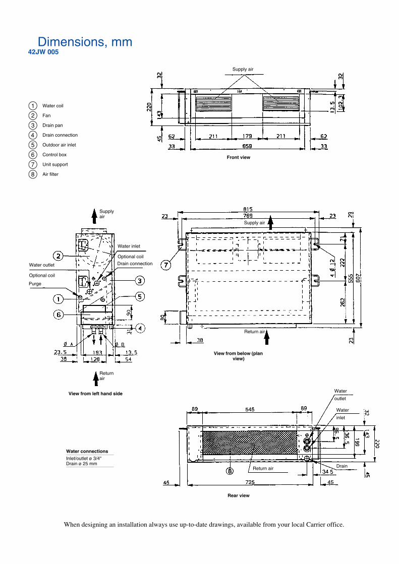
Dimensions, mm
42JW 005
Supply air
Supply air
Water inlet
Optional coil
Drain connectionWater outlet
Optional coil
Purge
Front view
Return air
View from left hand side
Water connections
Inlet/outlet ø 3/4"Drain ø 25 mm
Supply air
Return air
View from below (plan view)
Water
outlet
Water
inlet
DrainReturn air
Rear view
When designing an installation always use up-to-date drawings, available from your local Carrier office.
Water coil
Fan
Drain pan
Drain connection
Outdoor air inlet
Control box
Unit support
Air filter
12345678
4
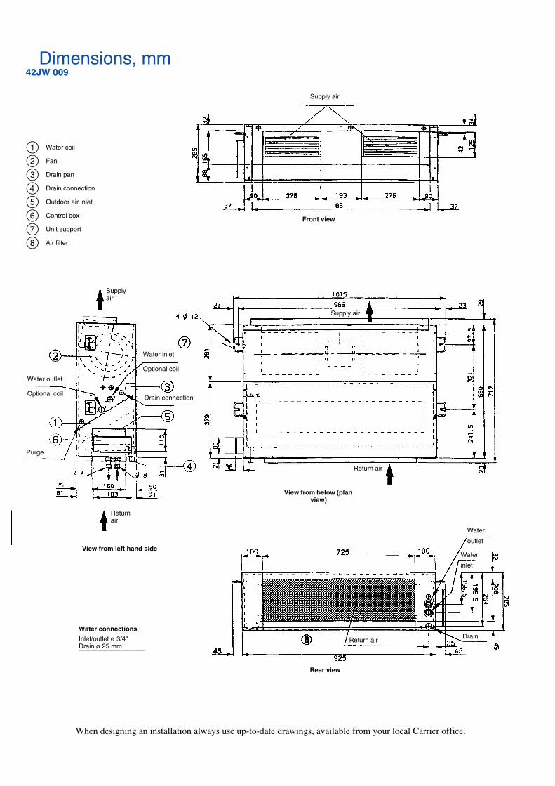
Dimensions, mm
42JW 009
Supply air
Supply air
Water inlet
Optional coil
Drain connection
Water outlet
Optional coil
Purge
Front view
Return air
View from left hand side
Water connections
Inlet/outlet ø 3/4"Drain ø 25 mm
Supply air
Return air
View from below (plan view)
Water
outlet
Water
inlet
DrainReturn air
Rear view
When designing an installation always use up-to-date drawings, available from your local Carrier office.
Water coil
Fan
Drain pan
Drain connection
Outdoor air inlet
Control box
Unit support
Air filter
12345678

5
Dimensions, mm
42JW 016
Supply air
Supply air
Water inlet
Optional coil
Drain connection
Water outlet
Optional coil
Purge
Front view
Return air
View from left hand side
Water connections
Inlet/outlet ø 3/4"Drain ø 25 mm
Supply air
Return air
View from below (plan view)
Water
outlet
Water
inlet
DrainReturn air
Rear view
When designing an installation always use up-to-date drawings, available from your local Carrier office.
Water coil
Fan
Drain pan
Drain connection
Outdoor air inlet
Control box
Unit support
Air filter
12345678

6
Required clearances, mm
Unit air filter access
Control box
Air flow
Air flow
Water connections
False ceiling

7
Cooling capacities, kW
(Standard coil, high speed)
Entering coil water temperature, °C
Ind
oo
r ai
r w
et b
ulb
tem
per
atu
re, °
CIn
do
or
air
dry
bu
lb t
emp
erat
ure
, °C
Sen
sib
le c
apac
ity,
kW
To
tal c
oo
ling
cap
acit
y, k
W
Wat
er t
emp
erat
ure
ris
e, K
Models
8
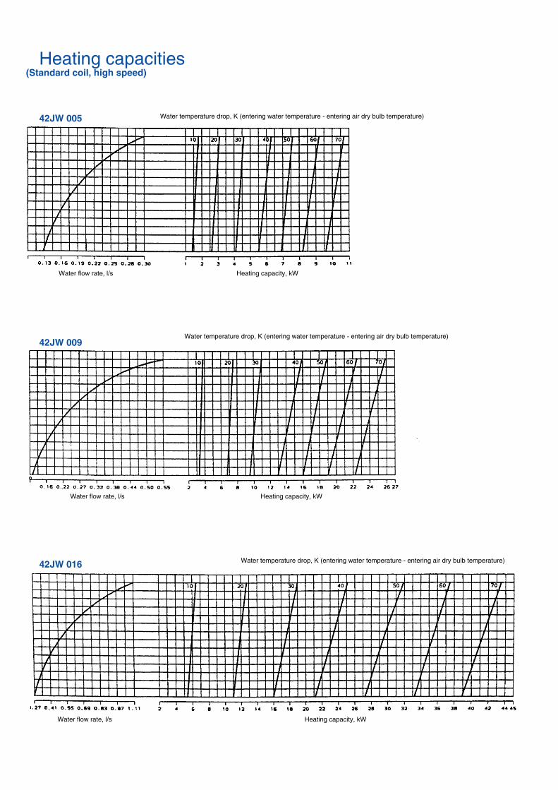
Heating capacities
(Standard coil, high speed)
42JW 005
42JW 009
42JW 016
Water flow rate, l/s Heating capacity, kW
Water flow rate, l/s Heating capacity, kW
Water flow rate, l/s Heating capacity, kW
Water temperature drop, K (entering water temperature - entering air dry bulb temperature)
Water temperature drop, K (entering water temperature - entering air dry bulb temperature)
Water temperature drop, K (entering water temperature - entering air dry bulb temperature)
9
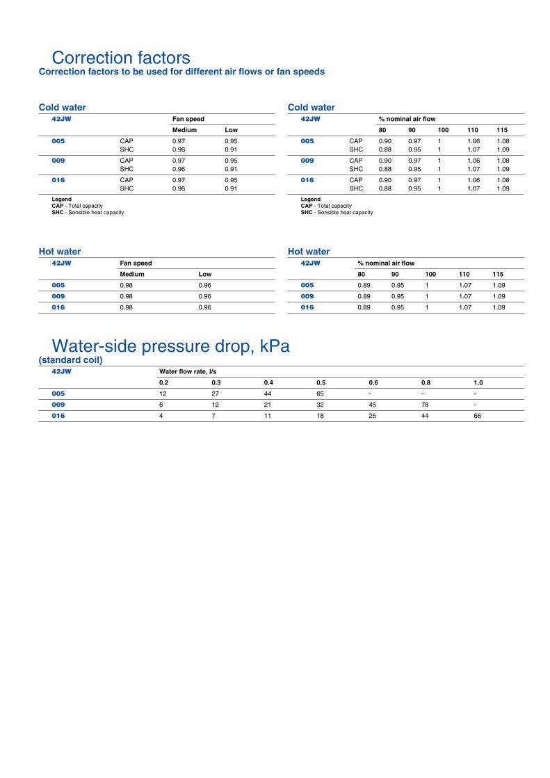
Correction factors
Correction factors to be used for different air flows or fan speeds
Cold water
42JW
Fan speed
Medium Low
005
CAP 0.97 0.95SHC 0.96 0.91
009
CAP 0.97 0.95SHC 0.96 0.91
016
CAP 0.97 0.95SHC 0.96 0.91
LegendCAP
- Total capacity
SHC
- Sensible heat capacity
Cold water
42JW
% nominal air flow
80 90 100 110 115
005
CAP 0.90 0.97 1 1.06 1.08SHC 0.88 0.95 1 1.07 1.09
009
CAP 0.90 0.97 1 1.06 1.08SHC 0.88 0.95 1 1.07 1.09
016
CAP 0.90 0.97 1 1.06 1.08SHC 0.88 0.95 1 1.07 1.09
LegendCAP
- Total capacity
SHC
- Sensible heat capacity
Hot water
42JW
Fan speed
Medium Low
005
0.98 0.96
009
0.98 0.96
016
0.98 0.96
Hot water
42JW
% nominal air flow
80 90 100 110 115
005
0.89 0.95 1 1.07 1.09
009
0.89 0.95 1 1.07 1.09
016
0.89 0.95 1 1.07 1.09
Water-side pressure drop, kPa
(standard coil)
42JW
Water flow rate, l/s
0.2 0.3 0.4 0.5 0.6 0.8 1.0
005
12 27 44 65 - - -
009
6 12 21 32 45 78 -
016
4 7 11 18 25 44 66

10
Fan performance curves
42JW 005 42JW 009
42JW 016
Ava
ilabl
e st
atic
pre
ssur
e, P
a
Air flow, l/s Air flow, l/s
Air flow, l/s
Ava
ilabl
e st
atic
pre
ssur
e, P
a
Ava
ilabl
e st
atic
pre
ssur
e, P
a
1 – Super high fan speed (optional)2 – High fan speed3 – Medium fan speed4 – Low fan speedAir flow rates are for a standard dry coil
Air flow, nominal static pressure and motor powerinput and current draw
Data given is for a standard dry coil at the same pressure (2-pipe installation)
42JW
005 009 016
High fan speed
Air flow l/s 182 411 686Static pressure Pa 45 50 80Motor power input W 100 305 560Motor current draw A 0.45 1.35 2.40
Medium
fan speed
Air flow l/s 149 350 615Static pressure Pa 45 50 80Motor power input W 90 247 460 Motor current draw A 0.40 1.1 2.0
Low fan speed
Air flow l/s 126 300 544Static pressure Pa 45 50 80Motor power input W 75 210 420Motor current draw A 0.35 1.0 1.9

11

12
Order No. 14214-20, 05.05. Supersedes order No. 14214-20, 02.03. Printed on Totally Chlorine Free Paper.Manufacturer reserves the right to change any product specifications without notice. Printed in the Netherlands.