Embed Size (px)
Citation preview

The 30HXC units are water-cooled chillers, designed from the ground up to meet the needs of today and tomorrow:- ecological HFC-134a refrigerant- screw compressors- fits through a standard door with no disassembly
required.- mechanically cleanable evaporators and condensers
All units are equipped with PRO-DIALOG Plus control to optimize the efficiency of the refrigerant circuit.
Features
�
Quality design and construction make the 30HXC unit the preferred choice.
�
Non-controlled, ozone-benign HFC-134a refrigerant. HCF-134a is a proven, non-toxic, non-flammable refriger-ant which will have the highest usage of any new refriger-ant.
�
Medium-pressure refrigerant HFC-134a minimizes stress on the compressors and ensures their long operating life.
�
The 30HXC units are equipped with screw compressors for extremely quiet operation and low-vibration levels.
�
The 30HXC units exceed the efficiency level of average industry standards for both full- and part-load operation, saving on operating costs, through lower electrical costs.
�
The 30HXC control is fully automatic. The leaving water temperature is continuously monitored to detect load and flow changes. This combination provides the most precise temperature control available.
�
Two independent refrigerant circuits - the second one takes over automatically, when the first one malfunctions, main-taining partial cooling under all circumstances.
�
Easy installation - the 30HXC chillers are supplied with a full refrigerant charge, and conveniently located power sup-ply and water inlet and outlet connections.
�
Auto-diagnostics - quick display of the machine status.
�
Multiple compressor concept for optimized part-load effi-ciency and minimized starting current.
�
Series star/delta starter, limiting the start-up current on 30HXC 080-190 units.
�
30HXC 080-375 units are also available as high condens-ing temperature and non-reversible heat pump versions (options 150 and 150A). Their application range is the same as for the standard units, on which they are based, but they also allow condenser leaving water temperatures of up to 63°C. PRO-DIALOG control offers all the advantages of the standard units, plus control of the leaving condenser water temperature.
30HXC - 60 HzOption 60 or 61
Nominal cooling capacity 284-1280 kW
Water-Cooled Screw Compressor Liquid Chillers
GLOBAL CHILLER

Easy installation
�
The 30HXC has a compact design that fits through a stand-ard door opening and requires minimal indoor space. The 30HXC is supplied as a complete package for easy installa-tion. There are no extra controls, timers, starters or other items to install.
�
30HXC units have a single power point and one main dis-connect/isolator switch for sizes 30HXC 080 to 190, and one power point and one main disconnect/isolator switch per circuit for sizes 30HXC 200 to 375.The hydraulic connections are simple and facilitated by the use of Victaulic connections for the evaporator and con-denser.
Simple to service
�
Mechanically-cleanable evaporator and condenser
�
Twin-screw compressors which require minimum routine service or maintenance.
�
Easily accessed suction and discharge pressure and tempe-rature information via a display module.
PRO-DIALOG Plus control
PRO-DIALOG Plus is an advanced numeric control sys-tem that combines intelligence with great operating simplic-ity.
PRO-DIALOG Plus ensures intelligent leaving water temperature control and optimises energy require-ments.
�
The PID control algorithm with permanent compensation for the difference between the heat exchanger entering and leaving temperature, anticipates load variations, guarantees leaving water temperature stability and prevents unneces-sary compressor cycling.
�
The long-stroke electronic expansion valves (EXV), together with refrigerant level control via heat exchange in the evaporator, allows a significant energy efficiency improvement at part load conditions, and faultless chiller operation in a wider temperature range.
�
Adjustable ramp loading, according to the inertia of the application, avoids load increases that are too fast and too frequent, increasing unit life and limiting power consump-tion peaks.
�
Several capacity loading possibilities ensure improved start-up at low outdoor air temperature, and permit use of one of the refrigerant circuits as a back-up circuit.
PRO-DIALOG Plus ensures preventive protection and enhances chiller reliability.
�
Equalisation of compressor operating hours
�
No capillary tubes or pressostats (except as safety device)
�
PRO-DIALOG Plus monitors all chiller safety parameters. The fault history function and the fault codes facilitate immediate location of faults and in certain cases the condi-tions causing the alarm. Prognostic and preventive mainte-nance functions (incorrect water loop, oil filter dirty etc.) permit anticipation of possible problems.
PRO-DIALOG Plus offers extended communications capabilities
�
Clear and easy-to-understand operator interface. The LEDs, numeric displays and touch keys are well-positioned on the schematic chiller diagram. The user immediately knows all operating parameters: pressures, temperatures, operating hours, etc.
�
The extensive chiller remote control capabilities (wired connection) allow integration into building monitoring sys-tems (see Technical Description)
�
RS485 series port for connection to the Carrier Comfort Network (CCN) or any other monitoring system (optional communications interface with open protocol allows trans-fer of almost 40 parameters).
�
Parallel piloting of two units as standard, or of several units with Flotronic System Manager (FSM) and Chiller System Manager (CSM III) options.
�
The control permits:- Control in master/slave configuration of two units operat-
ing in parallel.- Programming of operating time schedules (up to 8 peri-
ods per week)- Programming of operating time schedules for the second
set point (up to 8 periods per week)- Definition of operating time period with demand limit.- Integration of the unit into a building monitoring system
(BMS): serial port RS 485.
�
Control of the customer’s water pump (dual pump with automatic change-over optional).
�
Control at the second set point (example: room unoccu-pied).Set point reset as a function of the air temperature or the difference between entering and leaving water temperature.
Options and accessories
Option Accessory
Compressor suction valve X
Evaporator with one pass less X
Evaporator maximum water-side operating pressure of 21 bar X
Reversed evaporator water inlet/outlet X
Condenser with one pass less X
Condenser maximum water-side operating pressure of 21 bar X
Reversed condenser water inlet/outlet X
RS485 communications interface with open protocol X
Compressor soft start (30HXC 200-375) - electronic starter X
Electrical protection to IP44C X
Brine unit for leaving brine < +4°C to > -6°C X
High condensing temperature unit and non-reversible heat pump X
Tropicalized control box X
Disassembled unit X
Evaporator water pump starter X
Condenser water pump starter X
Three-way valve control, condenser X
Heat exchanger water connection kit X
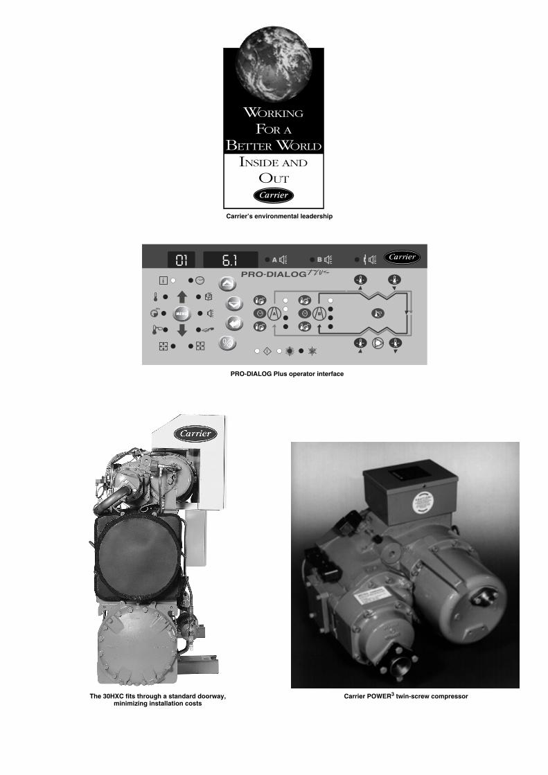
Carrier’s environmental leadership
PRO-DIALOG Plus operator interface
Carrier POWER
3
twin-screw compressor The 30HXC fits through a standard doorway, minimizing installation costs

Physical data
Electrical data 460 V – 60 Hz – option 60
30HXC 080 090 100 110 120 130 140 155 175 190 200 230 260 285 310 345 375
Net nominal cooling capacity*
kW 284 309 339 371 415 446 505 537 593 639 701 806 889 963 1081 1185 1280
Operating weight
kg 2274 2279 2302 2343 2615 2617 2702 2712 3083 3179 3873 4602 4656 4776 5477 5543 5721
Refrigerant charge**
HFC-134aCircuit A** kg 33 33 32 31 49 51 48 51 54 56 92 115 117 117 109 104 104Circuit B** kg 34 34 30 35 52 47 48 50 50 59 54 63 75 75 106 102 112
Compressors
Semi-hermetic, twin-screw POWER
3
Quantity - Circuit A 1 1 1 1 1 1 1 1 1 1 2 2 2 2 2 2 2Quantity - Circuit B 1 1 1 1 1 1 1 1 1 1 1 1 1 1 2 2 2Capacity control PRO-DIALOG Plus controlNo. of control steps 6 6 6 6 6 6 6 6 6 6 8 8 8 8 10 10 10Minimum step capacity % 19 19 21 19 21 19 17 19 21 21 14 14 14 14 10 10 10
Evaporator
Shell and tube with internally finned copper tubesNet water volume l 50 50 58 69 65 65 75 75 88 88 126 155 170 170 191 208 208Water connections Victaulic connectionsInlet/outlet in 4 4 4 5 5 5 5 5 5 5 6 6 6 6 8 8 8Drain and vent (NPT) in 3/8 3/8 3/8 3/8 3/8 3/8 3/8 3/8 3/8 3/8 3/8 3/8 3/8 3/8 3/8 3/8 3/8Max. water side operating pressure kPa 1000 1000 1000 1000 1000 1000 1000 1000 1000 1000 1000 1000 1000 1000 1000 1000 1000
Condenser
Shell and tube with internally finned copper tubesNet water volume l 48 48 48 48 78 78 90 90 108 108 141 190 190 190 255 255 255Water connections Victaulic connectionsInlet/outlet in 5 5 5 5 5 5 5 5 6 6 6 8 8 8 8 8 8Drain and vent (NPT) in 3/8 3/8 3/8 3/8 3/8 3/8 3/8 3/8 3/8 3/8 3/8 3/8 3/8 3/8 3/8 3/8 3/8Max. water side operating pressure kPa 1000 1000 1000 1000 1000 1000 1000 1000 1000 1000 1000 1000 1000 1000 1000 1000 1000
* Standard ARI conditions: Evaporator entering/leaving water temperature 12.2°C and 6.7°C. Condenser entering/leaving water temperature 29.6°C/35°C. Evaporator and condenser fouling factor = 0.000044 m
2
K/W.Not applicable to high condensing temperature units - please refer to electronic selection catalogue.
** The weights shown are guidelines only. For the unit refrigerant charge please refer to the unit nameplate.
30HXC
080 090 100 110 120 130 140 155 175 190 200 230 260 285 310 345 375
Power circuit
Nominal power supply (Un)* V-ph-Hz 460-3-60Voltage range V 414-506
Control circuit supply
The control circuit is supplied via the factory-installed transformer
Nominal power input*
kW 56 63 69 78 82 91 103 111 123 129 142 166 189 198 223 249 261
Nominal current drawn*
A 94 101 109 121 133 147 164 178 194 213 228 260 291 319 355 388 425
Max. power input**
kW 87 96 105 118 130 144 159 172 187 212 223 253 281 318 344 374 424Circuit A kW - - - - - - - - - - 144 159 187 212 172 187 212Circuit B kW - - - - - - - - - - 79 94 94 106 172 187 212
Max. current drawn (Un - 10%)***
A 134 147 161 180 200 220 243 263 286 324 340 386 429 486 526 572 648Circuit A A - - - - - - - - - - 220 243 286 324 263 286 324Circuit B A - - - - - - - - - - 120 143 143 162 263 286 324
Maximum current drawn (Un)***
A 122 134 146 164 182 200 221 239 260 294 309 351 390 441 478 520 588Circuit A A - - - - - - - - - - 200 221 260 294 239 260 294Circuit B A - - - - - - - - - - 109 130 130 147 239 260 294
Maximum starting current, standard unit (Un)****
A 165 165 177 201 219 244 274 292 313 363 685 801 840 979 928 970 1126Circuit A*** A - - - - - - - - - - 576 671 710 832 689 710 832Circuit B*** A - - - - - - - - - - 485 580 580 685 689 710 832
Max. starting current/max. current draw ratio, unit
1.35 1.23 1.21 1.23 1.20 1.22 1.24 1.22 1.20 1.23 2.22 2.28 2.15 2.22 1.94 1.87 1.91Max. starting current/max. current draw ratio, circuit A - - - - - - - - - - 2.88 3.04 2.73 2.83 2.88 2.73 2.83Max. starting current/max. current draw ratio, circuit B - - - - - - - - - - 4.44 4.46 4.46 4.66 2.88 2.73 2.83
Max. starting current - reduced current start (Un) ****
A std. std. std. std. std. std. std. std. std. std. 450 521 560 639 648 690 786Circuit A A std. std. std. std. std. std. std. std. std. std. 341 391 430 492 409 430 492Circuit B A std. std. std. std. std. std. std. std. std. std. 205 245 245 285 409 430 492
Max.starting current - red. current start/max. current draw ratio, unit
std. std. std. std. std. std. std. std. std. std. 1.70 1.77 1.65 1.67 1.71 1.65 1.67Circuit A std. std. std. std. std. std. std. std. std. std. 1.88 1.88 1.88 1.94 1.71 1.65 1.67Circuit B std. std. std. std. std. std. std. std. std. std. 1.46 1.48 1.44 1.45 1.36 1.33 1.34
Three-phase short circuit holding current
kA 25 25 25 25 25 25 25 25 25 25 N/A N/A N/A N/A N/A N/A N/ACircuit A kA - - - - - - - - -. - 25 25 25 25 25 25 25Circuit B kA - - - - - - - - - - 15 15 15 15 25 25 25
Customer standby power, unit or circuit B, for evaporator water pump connections†
kW 8 8 8 11 11 11 15 15 15 15 15 18 18 30 30 30 30
* Standard ARI conditions: Evaporator entering/leaving water temperature 12.2°C and 6.7°C. Condenser entering/leaving water temperature 29.6°C/35°C.** Power input, compressor, at unit operating limits (evaporator water entering/leaving temperature = 15°C/10°C, condenser entering/leaving water temperature = 45°C/50°C) and a nominal volt-
age of 460 V (data given on the unit name plate).*** Maximum unit operating current at maximum unit power input.
**** Maximum instantaneous starting current (maximum operating current of the smallest compressor(s) + locked rotor current or reduced starting current of the largest compressor)† Current and power inputs not included in the values above.
N/A Not applicable

Electrical data for units with high condensing temperatures 460 V – 60 Hz (option 60 + 150/150A)
30HXC 080 090 100 110 120 130 140 155 175 190 200 230 260 285 310 345 375
Power circuit
Nominal power supply (Un)* V-ph-Hz 460-3-60Voltage range V 414-506
Control circuit supply
The control circuit is supplied via the factory-installed transformer
Max. power input*
kW 107 119 131 146 162 180 196 214 231 277 279 312 347 415 429 462 553Circuit A kW - - - - - - - - - - 180 196 231 277 214 231 277Circuit B kW - - - - - - - - - - 99 116 116 138 214 231 277
Max. current drawn (Un - 10%)**
A 167 185 204 227 251 278 303 331 356 427 431 481 534 641 662 712 854Circuit A A - - - - - - - - - - 278 303 356 427 331 356 427Circuit B A - - - - - - - - - - 153 178 178 214 331 356 427
Maximum current drawn (Un)**
A 152 169 185 207 228 253 276 301 324 388 392 438 486 582 602 648 776Circuit A A - - - - - - - - - - 253 276 324 388 301 324 388Circuit B A - - - - - - - - - - 139 162 162 194 301 324 388
Maximum starting current, standard unit (Un)***
A 229 259 276 309 330 373 405 430 453 565 1073 1196 1244 1563 1359 1405 1758Circuit A*** A - - - - - - - - - - 934 1034 1082 1369 1059 1082 1369Circuit B*** A - - - - - - - - - - 820 920 920 1175 1059 1082 1369
Max. starting current/max. current draw ratio, unit
1.51 1.54 1.49 1.49 1.45 1.48 1.47 1.43 1.40 1.46 2.74 2.73 2.56 2.68 2.26 2.17 2.26Max. starting current/max. current draw ratio, circuit A - - - - - - - - - - 3.69 3.75 3.34 3.53 3.52 3.34 3.53Max. starting current/max. current draw ratio, circuit B - - - - - - - - - - 5.91 5.69 5.69 6.05 3.52 3.34 3.53
Max. starting current - reduced current start (Un) ***
A std. std. std. std. std. std. std. std. std. std. 663 736 784 923 899 945 1118Circuit A A std. std. std. std. std. std. std. std. std. std. 524 574 622 729 599 622 729Circuit B A std. std. std. std. std. std. std. std. std. std. 290 320 320 405 599 622 729
Max.starting current - red. current start/max. current draw ratio, unit
std. std. std. std. std. std. std. std. std. std. 2.07 2.08 1.92 1.88 1.99 1.92 1.88Circuit A std. std. std. std. std. std. std. std. std. std. 2.09 1.98 1.98 2.09 1.99 1.92 1.88Circuit B std. std. std. std. std. std. std. std. std. std. 1.69 1.68 1.61 1.58 1.50 1.46 1.44
Three-phase short circuit holding current
kA 25 25 25 25 25 25 25 25 25 25 N/A N/A N/A N/A N/A N/A N/ACircuit A kA - - - - - - - - -. - 25 25 25 25 25 25 25Circuit B kA - - - - - - - - - - 15 15 15 15 25 25 25
Customer standby power, unit or circuit B, for evaporator water pump connections†
kW 8 8 8 11 11 11 15 15 15 15 15 18 18 30 30 30 30
* Power input, compressor, at unit operating limits (evaporator water entering/leaving temperature = 15°C/10°C, condensing temperature = 68°C) and a nominal voltage of 460 V (data given on the unit name plate).
** Maximum unit operating current at maximum unit power input.*** Maximum instantaneous starting current (maximum operating current of the smallest compressor(s) + locked rotor current or reduced starting current of the largest compressor)
† Current and power inputs not included in the values aboveN/A Not applicable

Electrical data 380 V – 60 Hz – option 61
30HXC 080 090 100 110 120 130 140 155 175 190 200 230 260 285 310 345 375
Power circuit
Nominal power supply (Un)* V-ph-Hz 380-3-60Voltage range V 342-418
Control circuit supply
The control circuit is supplied via the factory-installed transformer
Nominal power input*
kW 56 63 69 78 82 91 103 111 123 129 142 166 189 198 223 249 261
Nominal current drawn*
A 114 123 132 146 161 178 198 215 235 257 276 315 352 386 430 469 515
Max. power input**
kW 87 96 105 118 130 144 159 172 187 212 223 253 281 318 344 374 424Circuit A kW - - - - - - - - - - 144 159 187 212 172 187 212Circuit B kW - - - - - - - - - - 79 94 94 106 172 187 212
Max. current drawn (Un - 10%)***
A 162 178 194 218 242 266 294 319 346 392 412 467 519 588 637 692 784Circuit A A - - - - - - - - - - 266 294 346 392 319 346 392Circuit B A - - - - - - - - - - 145 173 173 196 319 346 392
Maximum current drawn (Un)***
A 148 162 177 198 220 242 267 290 315 356 374 424 472 534 580 630 712Circuit A A - - - - - - - - - - 242 267 315 356 290 315 356Circuit B A - - - - - - - - - - 132 157 157 178 290 315 356
Maximum starting current, standard unit (Un)****
A 189 189 203 229 251 279 313 335 360 417 778 908 956 1113 1063 1113 1291Circuit A*** A - - - - - - - - - - 646 751 798 935 773 798 935Circuit B*** A - - - - - - - - - - 536 641 641 757 773 798 935
Max. starting current/max. current draw ratio, unit
1.28 1.16 1.15 1.16 1.14 1.15 1.17 1.16 1.14 1.17 2.08 2.14 2.02 2.08 1.84 1.77 1.81Max. starting current/max. current draw ratio, circuit A - - - - - - - - - - 2.67 2.81 2.54 2.63 2.67 2.54 2.63Max. starting current/max. current draw ratio, circuit B - - - - - - - - - - 4.05 4.07 4.07 4.25 2.67 2.54 2.63
Max. starting current - reduced current start (Un) ****
A std. std. std. std. std. std. std. std. std. std. 492 597 645 736 752 802 914Circuit A A std. std. std. std. std. std. std. std. std. std. 360 440 487 558 462 487 558Circuit B A std. std. std. std. std. std. std. std. std. std. 225 270 270 315 462 487 558
Max.starting current - red. current start/max. currentdraw ratio, unit
std. std. std. std. std. std. std. std. std. std. 1.31 1.41 1.37 1.38 1.30 1.27 1.28Circuit A std. std. std. std. std. std. std. std. std. std. 1.49 1.65 1.55 1.57 1.60 1.55 1.57Circuit B std. std. std. std. std. std. std. std. std. std. 1.70 1.72 1.72 1.77 1.60 1.55 1.57
Three-phase short circuit holding current
kA 25 25 25 25 25 25 25 25 25 25 N/A N/A N/A N/A N/A N/A N/ACircuit A kA - - - - - - - - -. - 25 25 25 25 25 25 25Circuit B kA - - - - - - - - - - 15 15 15 15 25 25 25
Customer standby power, unit or circuit B, for evaporator water pump connections†
kW 8 8 8 11 11 11 15 15 15 15 15 18 18 30 30 30 30
* Standard ARI conditions: Evaporator entering/leaving water temperature 12.6°C and 6.7°C. Condenser entering/leaving water temperature 29.6°C/35°C.** Power input, compressor, at unit operating limits (evaporator water entering/leaving temperature = 15°C/10°C, condenser entering/leaving water temperature = 45°C/50°C) and a nominal volt-
age of 380 V (data given on the unit name plate).*** Maximum unit operating current at maximum unit power input.
**** Maximum instantaneous starting current (maximum operating current of the smallest compressor(s) + locked rotor current or reduced starting current of the largest compressor)† Current and power inputs not included in the values above.
N/A Not applicable
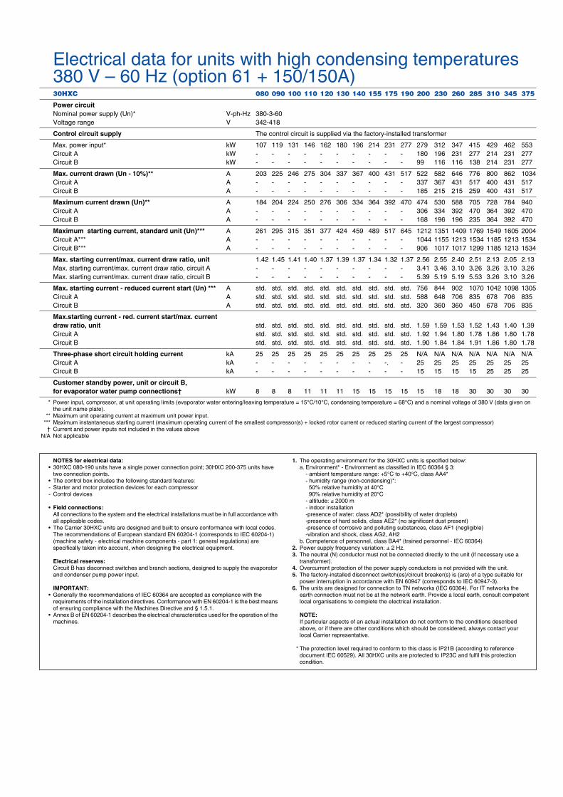
Electrical data for units with high condensing temperatures 380 V – 60 Hz (option 61 + 150/150A)
30HXC 080 090 100 110 120 130 140 155 175 190 200 230 260 285 310 345 375
Power circuit
Nominal power supply (Un)* V-ph-Hz 380-3-60Voltage range V 342-418
Control circuit supply
The control circuit is supplied via the factory-installed transformer
Max. power input* kW 107 119 131 146 162 180 196 214 231 277 279 312 347 415 429 462 553Circuit A kW - - - - - - - - - - 180 196 231 277 214 231 277Circuit B kW - - - - - - - - - - 99 116 116 138 214 231 277
Max. current drawn (Un - 10%)**
A 203 225 246 275 304 337 367 400 431 517 522 582 646 776 800 862 1034Circuit A A - - - - - - - - - - 337 367 431 517 400 431 517Circuit B A - - - - - - - - - - 185 215 215 259 400 431 517
Maximum current drawn (Un)**
A 184 204 224 250 276 306 334 364 392 470 474 530 588 705 728 784 940Circuit A A - - - - - - - - - - 306 334 392 470 364 392 470Circuit B A - - - - - - - - - - 168 196 196 235 364 392 470
Maximum starting current, standard unit (Un)***
A 261 295 315 351 377 424 459 489 517 645 1212 1351 1409 1769 1549 1605 2004Circuit A*** A - - - - - - - - - - 1044 1155 1213 1534 1185 1213 1534Circuit B*** A - - - - - - - - - - 906 1017 1017 1299 1185 1213 1534
Max. starting current/max. current draw ratio, unit
1.42 1.45 1.41 1.40 1.37 1.39 1.37 1.34 1.32 1.37 2.56 2.55 2.40 2.51 2.13 2.05 2.13Max. starting current/max. current draw ratio, circuit A - - - - - - - - - - 3.41 3.46 3.10 3.26 3.26 3.10 3.26Max. starting current/max. current draw ratio, circuit B - - - - - - - - - - 5.39 5.19 5.19 5.53 3.26 3.10 3.26
Max. starting current - reduced current start (Un) ***
A std. std. std. std. std. std. std. std. std. std. 756 844 902 1070 1042 1098 1305Circuit A A std. std. std. std. std. std. std. std. std. std. 588 648 706 835 678 706 835Circuit B A std. std. std. std. std. std. std. std. std. std. 320 360 360 450 678 706 835
Max.starting current - red. current start/max. currentdraw ratio, unit
std. std. std. std. std. std. std. std. std. std. 1.59 1.59 1.53 1.52 1.43 1.40 1.39Circuit A std. std. std. std. std. std. std. std. std. std. 1.92 1.94 1.80 1.78 1.86 1.80 1.78Circuit B std. std. std. std. std. std. std. std. std. std. 1.90 1.84 1.84 1.91 1.86 1.80 1.78
Three-phase short circuit holding current
kA 25 25 25 25 25 25 25 25 25 25 N/A N/A N/A N/A N/A N/A N/ACircuit A kA - - - - - - - - -. - 25 25 25 25 25 25 25Circuit B kA - - - - - - - - - - 15 15 15 15 25 25 25
Customer standby power, unit or circuit B, for evaporator water pump connections†
kW 8 8 8 11 11 11 15 15 15 15 15 18 18 30 30 30 30
* Power input, compressor, at unit operating limits (evaporator water entering/leaving temperature = 15°C/10°C, condensing temperature = 68°C) and a nominal voltage of 380 V (data given on the unit name plate).
** Maximum unit operating current at maximum unit power input.*** Maximum instantaneous starting current (maximum operating current of the smallest compressor(s) + locked rotor current or reduced starting current of the largest compressor)
† Current and power inputs not included in the values aboveN/A Not applicable
NOTES for electrical data:
• 30HXC 080-190 units have a single power connection point; 30HXC 200-375 units have two connection points.
• The control box includes the following standard features:- Starter and motor protection devices for each compressor- Control devices
•
Field connections:
All connections to the system and the electrical installations must be in full accordance with all applicable codes.
• The Carrier 30HXC units are designed and built to ensure conformance with local codes. The recommendations of European standard EN 60204-1 (corresponds to IEC 60204-1) (machine safety - electrical machine components - part 1: general regulations) are specifically taken into account, when designing the electrical equipment.
Electrical reserves:
Circuit B has disconnect switches and branch sections, designed to supply the evaporator and condenser pump power input.
IMPORTANT:
• Generally the recommendations of IEC 60364 are accepted as compliance with the requirements of the installation directives. Conformance with EN 60204-1 is the best means of ensuring compliance with the Machines Directive and § 1.5.1.
• Annex B of EN 60204-1 describes the electrical characteristics used for the operation of the machines.
1.
The operating environment for the 30HXC units is specified below:a. Environment* - Environment as classified in IEC 60364 § 3:
- ambient temperature range: +5°C to +40°C, class AA4*- humidity range (non-condensing)*:
50% relative humidity at 40°C 90% relative humidity at 20°C- altitude:
≤
2000 m- indoor installation-presence of water: class AD2* (possibility of water droplets)-presence of hard solids, class AE2* (no significant dust present)-presence of corrosive and polluting substances, class AF1 (negligible)-vibration and shock, class AG2, AH2
b. Competence of personnel, class BA4* (trained personnel - IEC 60364)
2.
Power supply frequency variation: ± 2 Hz.
3.
The neutral (N) conductor must not be connected directly to the unit (if necessary use a transformer).
4.
Overcurrent protection of the power supply conductors is not provided with the unit.
5.
The factory-installed disconnect switch(es)/circuit breaker(s) is (are) of a type suitable for power interruption in accordance with EN 60947 (corresponds to IEC 60947-3).
6.
The units are designed for connection to TN networks (IEC 60364). For IT networks the earth connection must not be at the network earth. Provide a local earth, consult competent local organisations to complete the electrical installation.
NOTE:
If particular aspects of an actual installation do not conform to the conditions described above, or if there are other conditions which should be considered, always contact your local Carrier representative.
* The protection level required to conform to this class is IP21B (according to reference document IEC 60529). All 30HXC units are protected to IP23C and fulfil this protection condition.

Operating limits
Condenser water flow rates
Evaporator water flow rates
30HXC
Minimum flow rate, l/s* Maximum flow rate, l/s**
Closed loop Open loop
080-110
2.3 7.0 28.2
120-130
3.1 9.3 37.1
140-155
3.7 11.1 44.5
175-190
4.3 13.0 51.9
200
4.9 14.8 59.2
230-285
6.7 20.1 80.4
310-375
8.0 24.0 95.9
* Based on a velocity of 0.3 m/s in a closed loop and 0.9 m/s in an open loop.** Based on a water velocity of 3.6 m/s.
30HXC
Minimum flow rate, l/s Maximum flow rate, l/s
080-090
5.2 20.8
100
6.5 25.9
110
7.4 29.6
120-130
8.3 33.4
140-155
9.4 37.8
175-190
11.5 45.9
200 14.1 56.3230 16.3 65.2260-285 18.3 73.4310 20.9 83.7345-375 23.0 91.9
Unit operating range at full load
Notes:1. Evaporator and condenser ∆T = 5 K2. For start-up at full load with a condenser water entering temperature below 20°C, a three-
way valve must be used to maintain the correct condensing temperature3. Maximum condenser water leaving temperature 50°C (at full load)A Standard unit operating at full load.B Standard unit operating at reduced load.C For transient operating modes (start-up and part load) the unit can operate down to
a condenser entering water temperature of 13°C.Units operating with head pressure control with analogue water control valve.
Additional operating range for high condensing temperature units and non-reversible heat pumps.
Evaporator leaving water temperature, °C
Con
dens
er w
ater
ent
erin
g te
mpe
ratu
re, °
C

Legend:All dimensions are given in mm.
Evaporator
Condenser
Required clearances for maintenance
Recommended space for tube removal (clearances D and E can be either on the right or the left hand side).
Water inlet
Water outlet
Power supply
NOTE:For a specific installation, consult the certified dimensional drawings, available on request.
C
4
3
3
4
A
3
30HXC08030HXC09030HXC10030HXC110
E
50
0
D
B
70
0
60
0
1
2
30HXC12030HXC13030HXC14030HXC15530HXC17530HXC190
F
C
E
500
700
D
B
A
600
3
3
4 4
3
1
2
F
30HXC 200-37530HXC A B C D E F
200 3903 1015 1980 3600 1000 489489 3924 1015 2060 3600 1000 489310-345-375 4533 1015 2112 4200 1000 503
30HXC A B C D E F
080-090-100 2558 980 1800 2200 1000 385110 2565 980 1850 2200 1000 385120-130-140-155 3275 980 1816 2990 1000 689175-190 3275 980 1940 2990 1000 689
Dimensions/clearances30HXC 080-190
1
2
3
4

Guide specificationsWater-cooled liquid chillers Size range: 284 to 1280 kW Carrier model number: 30HXC
Part 1 - General
1.01 System description� Microprocessor controlled, water-cooled liquid chiller uti-
lizing HFC-134a, dual refrigeration circuit, screw compres-sors and electronic expansion valves.
1.02 Quality assurance� Unit shall be rated in accordance with Eurovent standard.� Unit construction shall comply with European directives:
- Pressurised equipment directive (PED) 97/23/EC- Machinery directive 98/37/EC, modified- Low voltage directive 73/23/EEC, modified- Electromagnetic compatibility directive 89/336/EEC,
modified, and the applicable recommendations of Euro-pean standards:
- Machine safety: electrical equipment in machines, gen-eral regulations, EN 60204-1
- Electromagnetic emission EN 50081-2- Electromagnetic immunity EN 50082-2.
� Unit shall be designed, manufactured and tested at a facil-ity with a quality assurance system certified ISO 9001.
� Unit shall be manufactured at a facility with a environment management system certified ISO 14001.
� Unit shall be run tested at the factory.
1.03 Delivery, storage and handling � Unit controls shall be capable of withstanding 55°C storage
temperatures in the control compartment.
Part 2 - Products
2.01 Equipment� General
Factory assembled, single-piece, water-cooled liquid chiller. Contained within the unit cabinet shall be all fac-tory wiring, piping, controls, refrigerant charge (HFC-134a), required prior to field start-up.
� Compressors - Semi-hermetic twin-screw compressors with internal
muffler and check valve.- Each compressor shall be equipped with a discharge shut-
off valve.- Capacity control shall be provided by pilot-operated sole-
noid valve, capable of reducing unit capacity to 20% of full load. Compressor shall start in unloaded condition.
- Motor cooling shall be provided by direct liquid injec-tion and protected by internal overload thermistor.
- Lube oil system shall include pre-filter and internal filter capable of filtration to 3 microns.
� EvaporatorUnit shall be equipped with a single evaporator.- Shall be manufactured, tested and stamped in accordance
with the European directive for pressurised equipment 97/93/EC. The maximum refrigerant-side operating pres-sure will be 2500 kPa, and the maximum water-side pres-sure will be 1000 kPa.
- Shall be mechanically cleanable shell-and-tube type with removable heads.
- Tubes shall be internally-enhanced, seamless-copper type, and shall be rolled into tube sheets.
- Shall be equipped with Victaulic water connections (water connection kit on demand).
- Shell shall be insulated with 19-mm closed-cell, polyvi-nyl-chloride foam with a maximum K factor of 0.28.
- Shall have an evaporator drain and vent.- Design shall incorporate 2 independent refrigerant cir-
cuits.- Shall incorporate a refrigerant level control system.
� CondenserUnit shall be equipped with a single condenser.- Shall be manufactured, tested and stamped in accordance
with the European directive for pressurised equipment 97/93/EC. The maximum refrigerant-side operating pres-sure will be 2500 kPa, and the maximum water-side pres-sure will be 1000 kPa.
- Shall be mechanically cleanable shell-and-tube type with removable heads.
- Tubes shall be internally-enhanced, seamless-copper type, and shall be rolled into tube sheets.
- Shall be equipped with Victaulic water connections (water connection kit on demand).
- Design shall incorporate 2 independent refrigerant cir-cuits and the oil separator.
� Refrigeration circuitsRefrigerant circuit components shall include oil separators, high and low side pressure relief devices (according to applicable standards), discharge and liquid line shutoff valves, filter driers, moisture indicating sight glasses, expansion devices, refrigerant economizers (unit sizes 190, 285, 375), and complete operating charge of both HFC-134a refrigerant and compressor oil.
� Controls, Safeties, and Diagnostics 1. Controls a. Unit controls shall include as a minimum: the micro-
processor, the LOCAL/OFF/REMOTE/CCN selector and a 6-digit diagnostic display (scroll-down text) with keypad.
b. Shall be capable of performing the following functions:- Automatic change-over between the main compressor
and the non-active compressor(s).- Capacity control based on leaving chilled fluid temper-
ature with return fluid temperature sensing.- Limit the chilled fluid temperature pull-down rate at
start-up to an adjustable range of 0.1°C to 1.1°C per minute to prevent excessive demand spikes at start-up.
- Enable adjustment of leaving chilled water tempera-ture according to the return water temperature or by means of a 0-10 V signal.
- Provide a dual set point for the leaving chilled water temperature activated by a remote contact closure sig-nal.
- Enable a 2-level demand limit control (between 0 and 100%), activated by a remote contact closure or a 0 to 10 V signal.
- Control evaporator water pump, safety pump (if installed), and the condenser pump.
- Enable automatic changeover in the main phase or shutdown of two chillers in a single system.
- With two time scheduling programs enable unit start-up control and set-point change.

2. Diagnostics a. Display module shall be capable of displaying set
points, system status (including temperatures, pres-sures, currents for each compressor, run times and per-cent loading), and any alarm or alert conditions.
b. The control shall allow a quick test of all machine ele-ments to verify the correct operation of every switch, circuit breaker, contactor etc. before the chiller is started.
c. The control shall be capable of balancing the compres-sor operating times and the number of compressor start-ups.
d. EXV control, based on throttling (Carrier patent) opti-mises evaporator charging, ensuring condenser super-heat and subcooling.
3. SafetiesUnit shall be equipped with all necessary components, and in conjunction with the control system shall provide the unit with protection against the following: - Loss of refrigerant charge.- Reverse rotation.- Low chilled fluid temperature.- Low oil pressure.- Current imbalance.- Thermal overload.- High pressure.- Electrical overload.- Loss of phase.
� Operating characteristics- Unit shall be capable of starting up with 13°C entering
water temperature to the condenser.- Unit shall be capable of starting up with 25°C entering
water temperature to the evaporator.
� Electrical characteristics- Unit electrical power supply shall enter the unit at one
(30HX 080-190) or two locations.- Unit shall operate on 3-phase power supply without neu-
tral.- Unit with two compressors (30HX 080-190) shall have a
factory-installed, star-delta starter to limit electrical inrush current.
- Control voltage shall be supplied by a factory installed transformer.
- Unit shall be supplied with factory-installed, electrical disconnect switch/circuit breaker.
� FinishingElectrical cabinet colour: RAL 7035Compressor/heat exchanger colour: RAL 7037

Manufactured by: Carrier SA, Montluel, France.Order No. 13034-20, 01.2003. Supersedes order No. 13034-20. 10.1999. Printed on Totally Chlorine Free Paper.Manufacturer reserves the right to change any product specifications without notice. Printed in the Netherlands.