Embed Size (px)
Citation preview
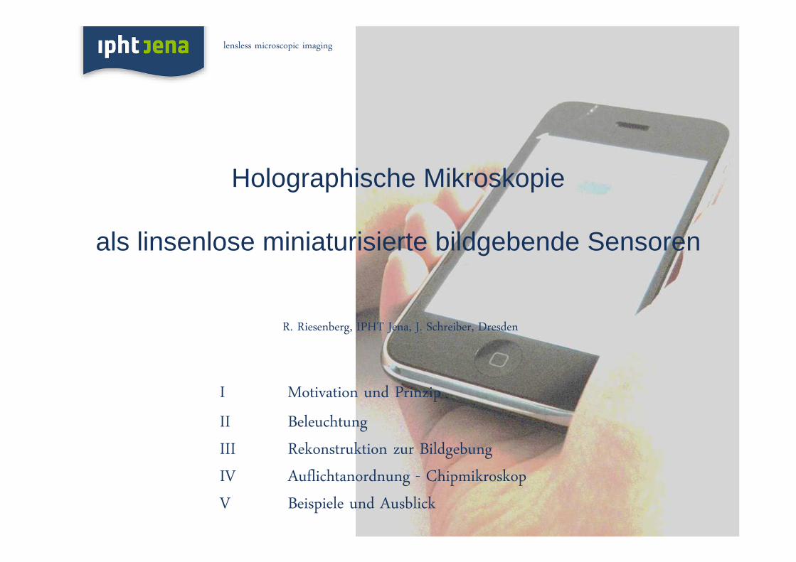
I Motivation und Prinzip
II Beleuchtung
III Rekonstruktion zur Bildgebung
IV Auflichtanordnung - Chipmikroskop
V Beispiele und Ausblick
Holographische Mikroskopie
als linsenlose miniaturisierte bildgebende Sensoren
R. Riesenberg, IPHT Jena, J. Schreiber, Dresden
lensless microscopic imaging

malaria-infected
Blood
sicked red blood
Cells, bars 10 µm
www.plosone.org, July 2009, Vol. 4, 7
Motivation
Mobile Phone based Microscope for Health Application
lensless microscopic imaging

blood cells
Motivation: Example blood cells imaging by
smartphone based
lensless microscope
Motivation: Example blood cells imaging by
smartphone based
lensless microscope
lensless microscopic imaging

Prinzip: Digital inline holographic microscope
D. Gabor, “A new
microscopic principle,“Nature 161, 777 (1948)
laser
screen
pinhole
object
CCD-chip
object on sample carrier
LED-chip and filter
pinhole-chip
lensless microscopic imaging

objektivfreie Mikroskopie 5
I(r) = |Aref + Ascat|2
= [A*ref Ascat+ Aref A*
scat + A*scatAscat + A*
refAref]
Linear in the scattered wave(Holographic diffraction pattern).
Interference between scattered waves
(Classical diffraction pattern) Unwanted nuisance!
To get rid of the reference beam intensity, the contrast hologram is formed
Ic(r) = I(r) -|A(r,t)|2
Object reconstruction is then performed via the Kirchhoff-Helmholtz transform
The reference and scattered waves combine
to form an interference pattern at the screen.
Digitale holografische inline-Mikroskopie
Laser Probe

LED-chip and filter
CCD-chip
pinhole-chip
Object
Full coherent illumination (coherence-length > 105 µm) by a DPSS laser causes coherent noise.
Right advanced imaging quality by micro-coherent illumination using a filtered LED with a coherence-length of 23 µm
Laser LED with filter
P. Petruck, R. Riesenberg, and R. Kowarschik,
Appl. Opt. 51, 2333-2340 (2012)
P. Petruck, R. Riesenberg, and R. Kowarschik,
Applied Physics B: 105, 339-348 (2012)
Illumination - reduced abbarations (speckle free)
lensless microscopic imaging
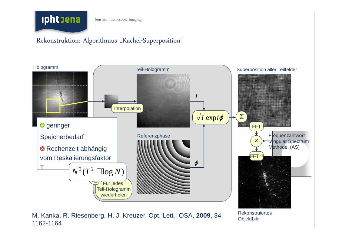
Rekonstruktion: Algorithmus „Kachel-Superposition“
Hologramm
Σ
Referenzphase
Für jedes Teil-Hologramm
wiederholen
Superposition aller Teilfelder
ϕ
I
ϕiI exp
Rekonstruiertes Objektbild
Frequenzantwort „Angular Spectrum“Methode, (AS)
×
FFT -1
FFT
Teil-Hologramm
Interpolation
geringer
Speicherbedarf
Rechenzeit abhängig vom ReskalierungsfaktorT
M. Kanka, R. Riesenberg, H. J. Kreuzer, Opt. Lett., OSA, 2009, 34, 1162-1164
)log( 22 NTN +
lensless microscopic imaging

Rekonstruktion: Beschleunigter Algorithmus
Referenzphase (Aliasing)
Position abh.
von f = (fx, fy)
Teil-Hologramm
Hologramm
zugehöriger Teil der Referenzphase(Aliasing)
ϕ
I
ϕiI exp
Σzentrierte Phase(ohne Aliasing)
ebene Phase der Frequenz
f = (fx, fy)
Rekonstruiertes Objektbild
Frequenzantwort „Angular Spectrum“Methode, (AS)
×
FFT -1
Fourier-Spektrumdes Teilfelds
FFT Σ
Superposition aller Fourier-Teilfelder
Für jedes Teil-Hologramm
wiederholen
TxT Teil-HologrammeInterpolationsfaktor T
Hologramm mit NxN PixelObjektbild mit NxN Pixel
geringer
Speicherbedarf
Rechenzeit
unabhängig
vom Reskalierungfaktor
M. Kanka, A. Wuttig, C. Graulig, R. Riesenberg, Opt. Lett., OSA, 2010, 35, 217-219
NN log2
lensless microscopic imaging

Probe: 1.06 µm PMMA-Kügelchen – Pinhole-Detektor-Abstand 4 mm
10 µm
Hologramm
NA = 0.75
Hologramm
NA = 0.75
NA = 0.70
HologrammHologramm
NA = 0.75
NA = 0.70
NA = 0.65
Hologramm
NA = 0.75
NA = 0.70
NA = 0.65
Rekonstruktion: Spatial resolution
lensless microscopic imaging
M. Kanka, R. Riesenberg, H. J. Kreuzer, Opt. Lett. 34, 1162 (2009)
M. Kanka, A. Wuttig, C. Graulig, R. Riesenberg, Opt. Lett. 35, 21 (2010)
M. Kanka, R. Riesenberg, P. Petruck, and Ch. Graulig, Opt. Lett. 36, 3651 (2011)

Auflichtanordnung - Chipmikroskop
lensless microscopic imaging

sample
pinhole chip
interferogram
on CCD chip
1 µm PMMA beads
Reconstruction brewer‘s yeast, resolution 1 µmReconstruction brewer‘s yeast, resolution 1 µmHologramHologram
Beispiel: Brewers yeast imagingBeispiel: Brewers yeast imaging
lensless microscopic imaging

objektivfreie Mikroskopie 12
Lensfree sensing on a microfluidic chip using plasmonic nanoapertures
B. Khademhosseinieh, G. Biener, I. Sencan, T.-W. Su, A. F. Coskun, and A. Ozcan
Appl. Phys. Lett. 97979797, 221107, 2010
Examples: Microfluidic Chip Microscopy, Lab-on-a-ChipExamples: Microfluidic Chip Microscopy, Lab-on-a-Chip

Laser Speckle Contrast Analysis (LASCA) images of the back of a hand, showing perfusion before and after gently
rubbing a small area.
Reduction in perfusion caused
by a rubber band
Part of a forearm, showing increased perfusion around a superficial
hot-water burn
Applications
Beispiele: Specklephotometrie in der Medizin

Speckle Contrast = σ / ⟨ I ⟩ ≤ 1, σ – standard deviation
Speckle contrast imaging for measuring blood flow
Single-exposure speckle photography – raw image of part of a retina (left), and its processed version (right).
a) “Health Eye” = Retina stimulator with monitoring unit
b) Ocular Microtremor Laser Speckle Metrology
c) Heart Pulse Variability monitoring (Speckle time dependence)
Applications
Beispiele: Specklephotometrie und in der Medizin

blood cells
Zusammenfassung: Smartphone based lensless microscopeZusammenfassung: Smartphone based lensless microscope
lensless microscopic imaging

Ausblick
• Linsenloses Chip-Mikroskop„Kachel-Superpositionsprinzip“ state-of-the-art Auflösung, 800 nm
Speckle-frei mit LED
Auflichtanordnung
Auflösung … 100 nm