Embed Size (px)
Citation preview

________________________________________________________________________
________________________________________________________________________
Hilton Hotel at BWI Airport Linthicum Heights, MD
Technical Report 1 Existing Conditions
Thomas Sabol
Structural Dr. Ali M. Memari
October 5, 2006

Thomas Sabol Technical Report 1 ________________________________________________________________________
TABLE OF CONTENTS
1.1 Executive Summary…………………………………………………………………...1 2.1 Structural System Description…………………………………………………….......2 2.2 Structural Summary…………………………………………………………………...2 2.3 Ground Level Framing Plan………………….………………………………………..2 2.4 Ground Level Framing Plan…………………………………………………………...3 2.5 Second Floor Framing Plan…………………………………………………………3-4 2.6 Third Floor Framing Plan……………………………………………………………..4 2.7 Fourth Floor Framing Plan……………………………………………………….....4-5 2.8 Penthouse Floor and Roof Plan…………………………………………………..........5 2.9 Penthouse Roof Framing Plan……………………………………………………...…5 2.10 Lateral Load Resistance System……………………………………………………..5 3.1 Loads…………………………………………………………………………………..6 3.2 Gravity Loads………………………………………………………………………6-7
3.2.1 Snow Loads………………………………………………………………….8
3.2.2 Gravity Load Spot Checks…………………………………………………..8
3.2.2.1 Column Spot Checks…………………………………………8-10
3.2.2.2 Punching Shear Spot Checks…………………………………….10 3.3 Lateral Loads………………………………………………………………………...10 3.3.1 Wind Loading…………………………………………………………..10-12 3.3.2 Seismic Loading………………………………………………………..12-14 3.3.3 Shear Wall Check……………………….....................................................14 4.1 Conclusions…..............................................................................................................15

Thomas Sabol Technical Report 1 ________________________________________________________________________
1.1 EXECUTIVE SUMMARY
The Hilton Hotel at the BWI Airport is located in
Linthicum Heights, MD. The size of the hotel is
203,300 s.f. and elevates from the ground eleven
stories plus a mechanical penthouse. This 280
guestroom hotel houses a ballroom/ assembly
room, pool with an indoor/ outdoor sundeck,
restaurant, and an 80-car parking garage below
grade. The cost of construction was roughly $35 million which began April 25, 2005 and
was substantially completed on September 21, 2006.
Technical Report 1 is an existing conditions report. Structural systems of the building are
described within this report. The main structural system of the building is cast-in-place
reinforced concrete. Typical hotel room floors are two-way post tensioned concrete
slabs. Loading conditions and calculations are given in tables throughout the report.
Gravity loads, both Live and Dead were computed for a given area where spot checks
were calculated. Spot checks on one column in two different levels were checked for
nominal strengths. Columns were more than sufficient to carry pure axial loads.
Punching shear checks were also evaluated in two locations, the 6th floor and the ground
floor. The 6th floor location is a flat two-way post tension slab, while the ground floor is
a two-way mild reinforced slab with drop panels. Both locations were sufficient to carry
the shear forces due to the factored gravity loads.
Lateral load calculations were computed for the building. Seismic results produced a
larger base shear than that calculated by the Engineer of record. Wind loading results
were within 10% of the results of the Engineer of Record’s calculations. A shear wall
check for direct shear produced by lateral loads was calculated on two shear walls. The
results yielded that the design strength surpassed the direct shear force on each wall.

Thomas Sabol Technical Report 1 ________________________________________________________________________
________________________________________________________________________ Page 2
2.1 STRUCTURAL SYSTEM DESCRIPTION
This section gives a summary of the structural system as well as a description of the
system floor by floor, the foundation and the lateral load resistance system.
2.2 STRUCTURAL SUMMARY
The structural system of the Hilton Hotel at the BWI Airport varies throughout the
building. The primary structural system of the building is cast-in-place reinforced
concrete. The typical floor system (floors 4-11) is a two-way post tensioned concrete
slab. Floors ground through three are a two-way mild reinforced concrete slab with drop
panels. The penthouse roof deck is a two-way post-tensioned reinforced concrete slab
with concrete beams. The columns transfer load to he foundation which are typical
spread footings. The lateral resistance system is a series of shear walls that extend up
from the foundation through the building. These shear walls transfer load to a mat
foundations.
The double-heighted ballroom, adjacent assembly room, and main entrance spaces are all
enclosed by a structural steel system. This system consists of various shape beams,
girders, and joists with a corrugated metal deck roof.
2.3 FOUNDATION AND PARKING LEVEL
Columns transfer gravity load to the foundation. The foundation consists of reinforced
concrete spread footings ranging in size of (3’-0” by 3’0” by 12”) to (10’-0” by 10’-0” by
40”). Lateral loads carried by the series of 12 shear walls transfer load to reinforced
concrete mat foundations. Concrete used in footing is specified to reach a 28-day f’c =
3000 psi.
The floor system for the Parking Level is a 5” Slab-On-Grade (SOG) reinforced with 6x6
w2.0 x w2.0 WWF. A concrete strength of f’c = 3500 psi was specified for the SOG.

Thomas Sabol Technical Report 1 ________________________________________________________________________
________________________________________________________________________ Page 3
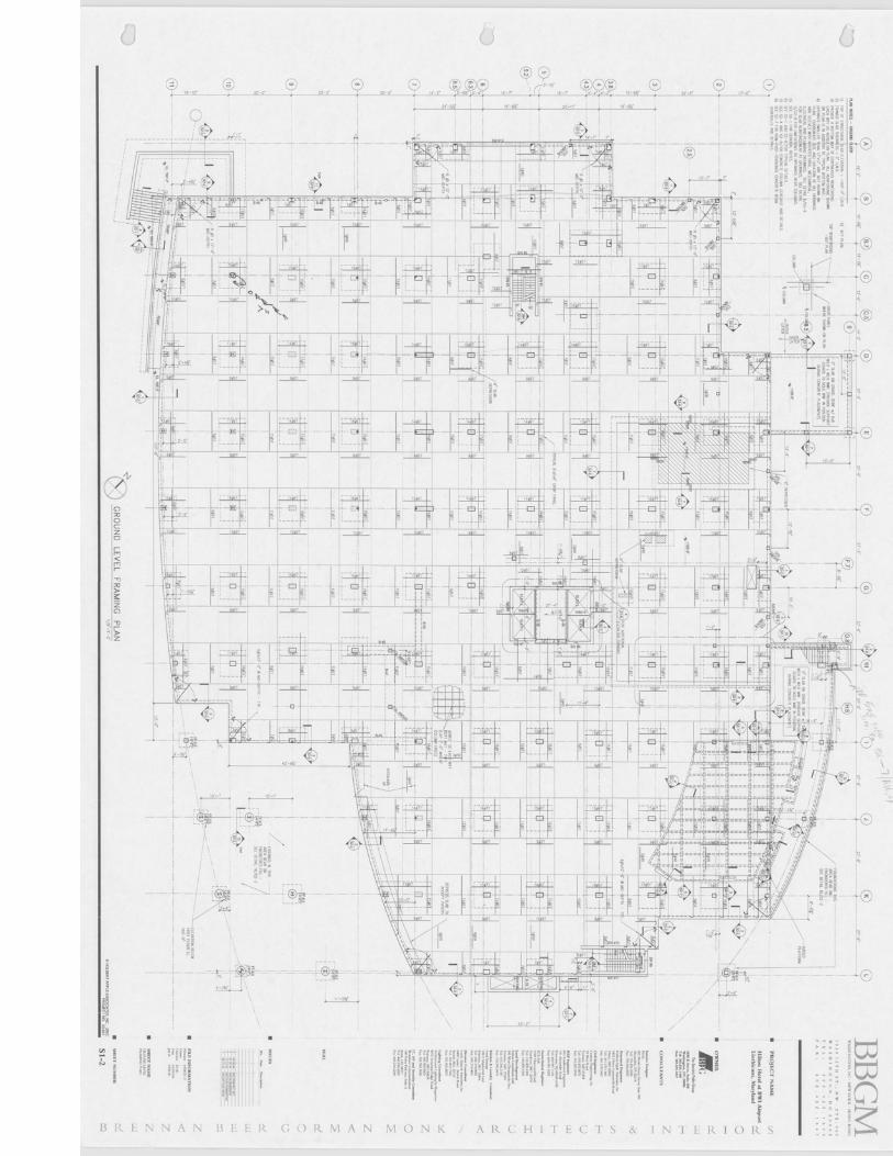
2.4 GROUND LEVEL FRAMING PLAN
The ground level floor system consists of a two-way mild reinforced 9” thick concrete
slab with typical 9’x9’x4” drop panels around the columns. The bottom reinforcement in
the concrete slab consists of #5 bars at 12” o.c. each way. The top of slab reinforcement
varies in reinforcing bars.
Concrete columns are typically spaced 27’-0” o.c. Columns vary in size: 14x14 12x12
14x26 18x18
14x76 18x26
16x16 26x14
16x28
Concrete columns are specified to reach a 28-day f’c = 5600 psi.
2.5 SECOND FLOOR FRAMING PLAN
The second floor is similar to the ground floor framing. The floor system is a two way
mild reinforced concrete slab with typical 9’x9’x4” drop panels around the columns.
Slab thickness is 9”. Bottom reinforcement in the concrete slab consists of #5 bars at 12”
o.c. each way. Top of slab reinforcement varies in reinforcing bars.
Column sizes are 14x26 and 16x28. Columns are also specified to reach a 28-day f’c =
5600 psi. There is a Transfer Girder near the elevator shear walls. This girder transfers
load from columns on level two to columns on the ground level which are offset from the
columns on level two.
The double-heighted ballroom, adjacent assembly room, and main entrance spaces are all
enclosed by a structural steel system. This area also contains a pool but the pool structure
is composed of epoxy-coated reinforced concrete transferring load to W-shape steel
columns embedded in concrete. Adjacent to the pool area is a reinforced concrete roof
deck framed with reinforced concrete beams. This roof deck runs flush with the metal
roof deck over the assembly room. See Appendix B Drawings.

Thomas Sabol Technical Report 1 ________________________________________________________________________
________________________________________________________________________ Page 4
The adjacent assembly room roof is framed out with 20LH4 shape steel members with a
3” deep 18 gage galvanized metal deck. Load transferred from these shapes to typical
W16x40 beams transfer load to W-shape columns.
The main entrance roof is framed out with 3” deep 18 gage galvanized metal deck which
transfers load to LH-shape steel joists which then transfers the load to W-shape beams to
W-shape steel columns.
2.6 THIRD FLOOR FRAMING PLAN
The third floor is a two-way mild reinforced concrete slab with with typical 9’x9’x4”
drop panels. Slab thickness is 9”. Bottom reinforcement in the concrete slab consists of
#5 bars at 12” o.c. each way. Top of slab reinforcement varies in reinforcing bars.
The ballroom area on this floor level has a system of 3-W8x31 Girders spanning East-
West in two locations to partially support the roof and also support folding partitions that
are hung using MC-shape steel from the 3-W8x31 system. Joists carry the remaining
load of the roof over the ballroom. Roughly 75% of the metal deck area over the
ballroom transfers loads to typical 52DLH13 joists 9’-0” o.c. The rest of the metal deck
transfers loads to 52DLH16 joists 4’-6” o.c. Joists transfer loads to W16x50 to W-shape
steel columns on the south-west side. On the opposite end joists transfer loads to
reinforced concrete beams integrated into the adjacent floor slab.
The roof decks are 3” deep 18 gage galvanized metal deck. The load over the pool area
roof transfers to typical W27x94 beams which transfer the load to W-shape steel
columns.
2.7 FOURTH THROUGH ELEVENTH FLOOR FRAMING PLAN
Floors four through eleven are typical framing plans. These are the hotel room floors.
The floor system is a two-way post-tensioned reinforced concrete slab. The floor
thickness is 7-1/2” with a specified f’c = 4000 psi. The bottom reinforcing consists of #4
bars 30” o.c. in both directions. Tendons spanning North – South are tensioned at 24
k/ft. Interior tendons spanning East – West are tensioned at 295k. End tendons spanning

Thomas Sabol Technical Report 1 ________________________________________________________________________
________________________________________________________________________ Page 5
East – West are tensioned at 135k on the North side while at 215k on the South side. Two
pour strips each 4’-0” wide were left open to tension tendons. Columns sizes are 14”x26”
and 16”x28” with a specified f’c = 4000psi.
See Appendix B Drawings for typical framing plan.
2.8 PENTHOUSE FLOOR AND ROOF PLAN
The penthouse floor system is similar to the typical floors of four through eleven. The
floor system is a two-way post-tensioned reinforced concrete slab. Floor slab thickness is
9” with a specified f’c = 4000 psi. Bottom reinforcing consists of #5 bars 24” o.c. in both
directions. Two pour strips each 4’-0” wide were left open to tension tendons.
Columns sizes are 14”x26”, 14”x14”and 16”x28” with a specified f’c = 4000 psi.
2.9 PENTHOUSE ROOF FRAMING PLAN
The penthouse roof framing is two-way post-tensioned reinforced concrete slab with
typical 18” drop beams. The roof slab thickness is 7-1/2” with a specified f’c = 4000 psi.
The bottom reinforcing consists of #4 bars 30” o.c. in both directions.
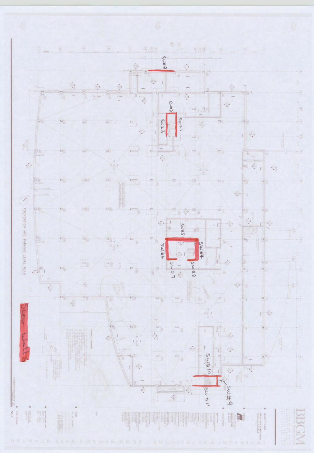
2.10 LATERAL LOAD RESISTANCE SYSTEM
The lateral load resistance system is a series of twelve reinforced concrete shear walls,
eleven of which are located in three locations: around two stairwells near either edge of
the north and south sides, and an elevator core in the center of the building. The twelfth
shear wall is located on the North side of the building and only spans vertically from
foundation to the second floor. Three shear walls are located around each stairwell and
five are located around the elevator core. Shear walls are 1’-0” thick specified f’c = 4000
psi. Shear walls transfer load to mat foundations previously mentioned.

Thomas Sabol Technical Report 1 ________________________________________________________________________
________________________________________________________________________ Page 6
3.1 LOADS
This section includes all required loading conditions including gravity, wind, and seismic
as well as spot checks of the original design. Codes and references used in this section
were ASCE7-05, Design of Concrete Structures 13th Edition. The concrete text book
references the ACI code.
All the codes and references that the Engineer of Record used for the project may be
found Appendix A.
3.2 GRAVITY LOADS
Dead loads used in calculations for spot checks were a combination of structure self
weight and superimposed dead loads used by the Engineer of Record. See Table 3.1
Area PSF
Roofs 30
Penthouse Roof 40
Penthouse Floor 20
Guestroom Floors 10
Second Floor 10
First Floor 10
Pool Deck 40 Table 3.1 Engineer of Record Superimposed Dead Loads

Thomas Sabol Technical Report 1 ________________________________________________________________________
________________________________________________________________________ Page 7
The Engineer of Record references the Live Loads from ASCE7-02. Table 3.3 shows the
loads used for the given areas.
Area PSF Area PSF
Roof Live Load 30 Garage Level 150
Penthouse Floor 150 Pool Deck 100
Guestroom Floors 40 First Floor 100
Second Floor 100 First and second Floor Storage Kitchen and
Laundry
125
Second Floor
Mechanical Rooms
150 Meeting Rooms 100
Meeting Rooms 100 Stairs 100
Stairs 100
Garage Level 150 Table 3.2 Engineer of Record Live Loads
Live loads used for spot check calculations come from ASCE7-05 can be found in Table
3.3. Live loads used in gravity load spot checks were chosen from ASCE7-05 to try to
match the loads used by the engineer. An occupancy type for mechanical rooms could
not be found, so therefore the load was taken from the Engineer of Record.
Live Loads (psf) ASCE7-05
Dance halls and ballrooms 100
Dining rooms & restaurants 100
Private rooms & corridors serving them 40
Public rooms & corridors serving them 100
Storage warehouses – Light 125 Table 3.3 ASCE7-05 Live Loads
Live load reductions factors were taken from ASCE7-05 and used in spot check
calculations.

Thomas Sabol Technical Report 1 ________________________________________________________________________
________________________________________________________________________ Page 8
3.2.1 Snow Loads
Snow loads were calculated using Chapter 7 of ASCE-05. The Engineer of Record
references ASCE7-02. Both years of the code yields the same roof snow load. Table 2.3
shows the factors used in the roof snow load calculation. The flat roof snow load was
calculated only. Unbalance drifting and sliding snow where not taken into consideration
for this technical report.
Factors Engineer of Record
ASCE7-02
Experimental Data
ASCE7-05
Ground Snow Load(Pg) 25 PSF 25 PSF
Snow Exposure (Ce) 0.9 0.9
Importance Factor (Is) 1.0 1.0
Roof Thermal (Ct) 1.0 1.0
Flat Roof Snow Load 16 PSF 16PSF
Table 3.4 Snow Load
3.2.2 Gravity Load Spot Checks
Gravity load spot checks were evaluated to compare experimental data and results of the
Engineer of Record’s original design. Columns were checked in two locations for
strength. Punching shear was checked in two locations: at a drop panel on the ground
floor and on a flat slab on the 6th floor. Punching shear was checked instead of flexure of
the floor systems due to shear most likely being the controlling factor. This assumption
was given by a consultant.
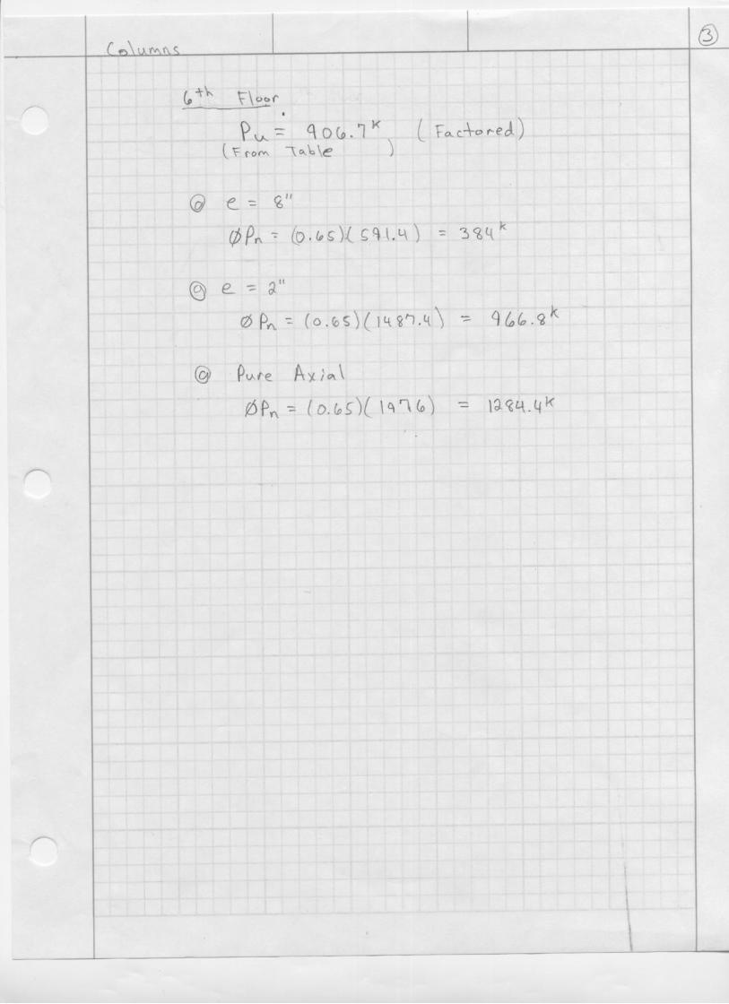
3.2.2.1 Column Spot Checks
Column spots checks were performed on one column (F-5.2), in two locations (6th floor
and Ground floor). Calculated column factored loads per floor compared to the Engineer
of Record’s unfactored loads are shown in Table 3.5. The load combination shown

Thomas Sabol Technical Report 1 ________________________________________________________________________
________________________________________________________________________ Page 9
controlled over all other applicable ASCE7-05 “Basic Combinations” found in section
2.3.2 of the code.
Experimental Data Gravity Loads (k)
Engineer of Record Gravity Loads (k)
1.2D + 1.6L+ 0.5Lr Unfactored 58.30 60
374.09 208462.88 279551.64 350640.39 420729.14 490817.90 560906.65 631995.40 701
1084.15 7711185.31 8411321.56 9681457.82 1088
Table 3.5 Load on Column F-5.2
Columns were checked for nominal strength in pure axial and combined loading. The
combined loading strength calculations were performed using the Design Aid A.6 in the
Design of Concrete Structures textbook.
Two eccentricities were used in determining combined loading nominal strength. An
eccentricity which would produce the largest moment and an eccentricity near the
bending axis were used. The combined loading using the largest eccentricity, for
columns in both locations, produced insufficient strength to carry the factored gravity
loads calculated for those columns. For the eccentricity taken at 2” from the bending
axis, the column on the 6th floor had sufficient strength while the column on the ground
floor was not adequate by about 50 kips. See calculations in the Appendix C “Column
Strength Check”. Further investigation on the moments on the column induced by the
floor slab will come in later technical reports. This check was just preliminary since
moments were not calculated on columns but were assumed by eccentricities.

Thomas Sabol Technical Report 1 ________________________________________________________________________
________________________________________________________________________ Page 10
Nominal pure axial strengths of the columns were sufficient to carry the factored gravity
loads on the column computed in the experimental data. See calculations in the
Appendix C “Column Strength Check”.
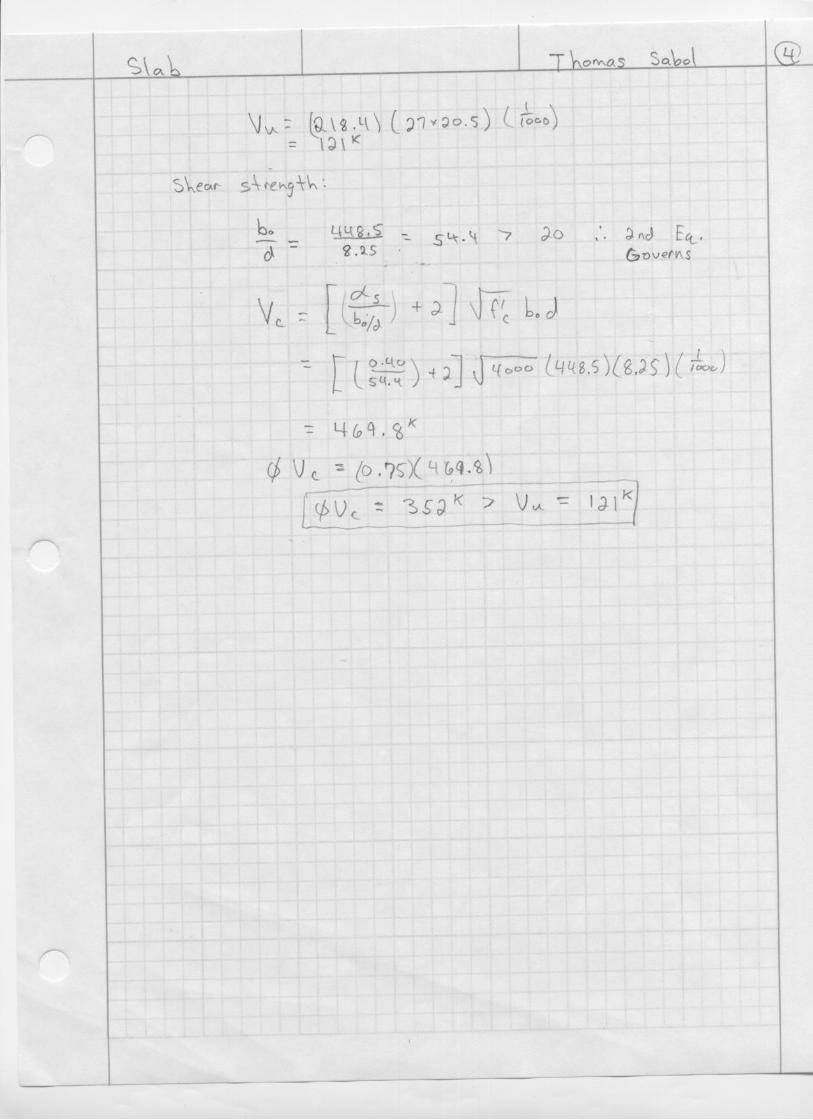
3.2.2.2 Punching Shear Spot Checks
Punching shear spot checks were taken from two locations around the column F-5.2. The
first location on the 6th floor, is a 7-1/2” two-way post tension slab. The second location
was on the ground floor where the floor is a 9” thick two-way mild reinforced slab with a
9’x9’x4” drop panel.
Nominal shear capacities of the concrete in both locations were adequate enough to carry
the punching shear force produced by the gravity loads. See calculations in Appendix C
“Punch Shear Slab Check”.
3.3 LATERAL LOADS
Lateral Loads were computed using excel spread sheets. Electronic copies of the spread
sheets can be obtained upon request. Procedures and equations for wind and seismic
loads are referenced to ASCE7-05 Chapters 6, 11, 12 and 19.
3.3.1 Wind Loading
Assumptions:
Exposure B Case 2 values were used for finding the Kh values from Table 6-3 in Chapter
6 of ASCE7-05. Kh values were conservatively used for simplification of wind loads at
varying floor heights, e.g. the floor to floor height of the 1st floor is 18 ft. A Kh value of
0.62 (Kh value at 20 ft) was used in the computation instead of breaking the loading up
into two Kh values per floor ( 0-15 ft and 20 ft loading). The width and lengths used in
the calculations were taken from the base length and width of the building.

Thomas Sabol Technical Report 1 ________________________________________________________________________
________________________________________________________________________ Page 11
Conditions:
Factors Engineer of Record
ASCE7-02
Experimental Data
ASCE7-05
Basic Wind Speed 90 mph 90 mph
Building Category II II
Site Exposure B B
Importance Factor 1.0 1.0
Windward Leeward Windward Leeward External Pressure
Coefficient GCP + 0.68 - 0.43 + 0.73 - 0.64
Internal Pressure
Coefficient GCPi +/- 0.18 +/- 0.18
Table 3.6 Wind Factors
Results:
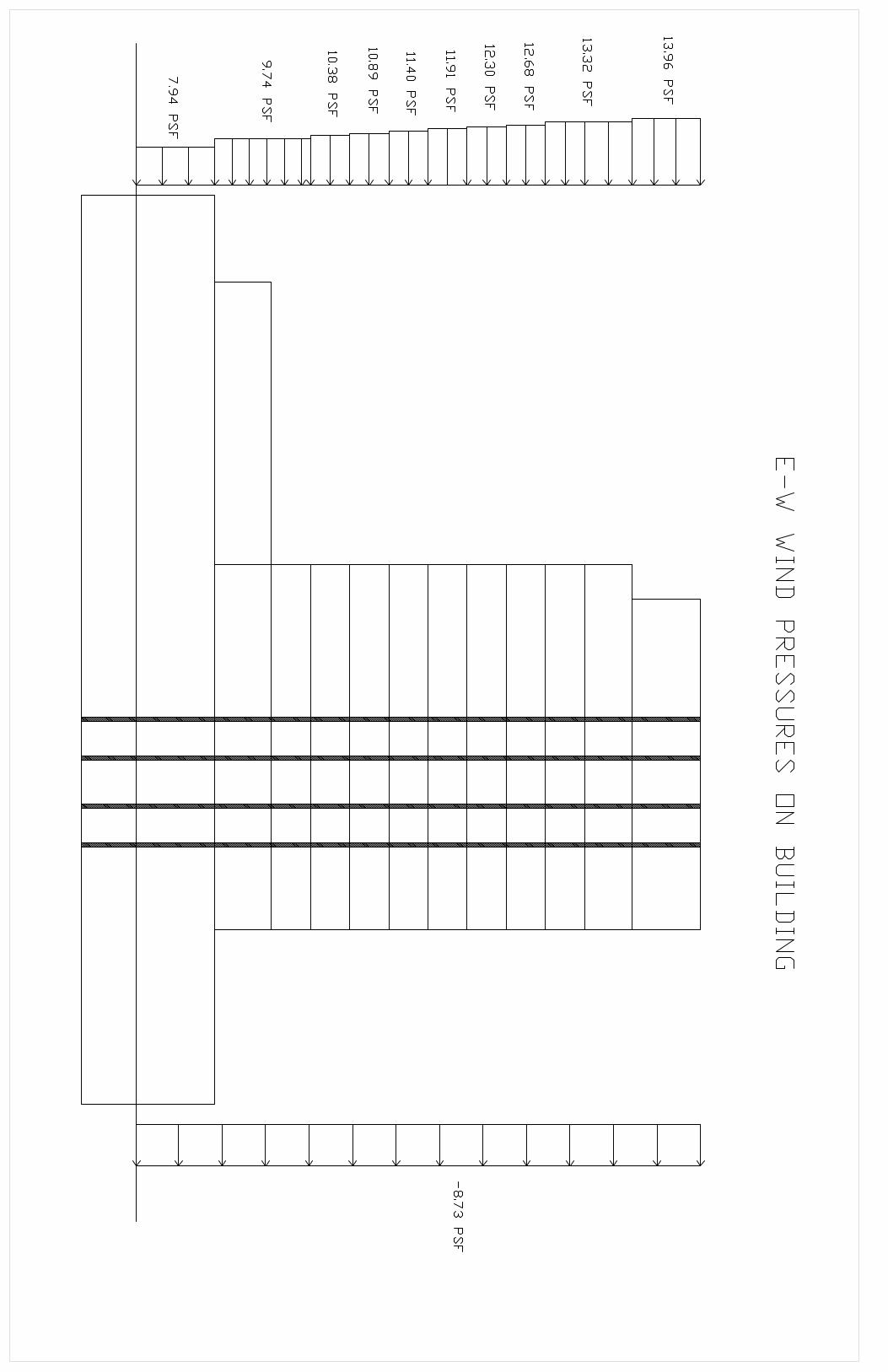
The wind load calculations yielded a pressure of 19.22 psf in the N-S direction and a
pressure 22.69 psf in the E-W direction at the top of the building. A wind loading
diagram of the building can be found in the E-W direction in Appendix B. The windward
GCP of +0.73 was calculated compared to the original design value of +0.64. This value
is within 10% of the original design. Discrepancies may be found in the calculation gust
factor calculations where certain values might have been assumed differently by either
party. Table 3.7 breaks down the pressures, shears, and overturning moment at each
level.

Thomas Sabol Technical Report 1 ________________________________________________________________________
________________________________________________________________________ Page 12
Pressures Shears (k) Overturning Moment Level hx
NS windward
NS leeward
EW windward
EW leeward N/S E/W N/S E/W
Penthouse 129.67 13.98 -5.24 13.96 -8.73 0.00 0.00 9515.57 13466.5711 114 13.34 -5.24 13.32 -8.73 49.81 70.86 5677.81 8077.97710 103 13.34 -5.24 13.32 -8.73 90.56 128.84 4197.23 5971.519
9 94 12.70 -5.24 12.68 -8.73 129.90 185.13 3698.28 5291.4288 85 12.31 -5.24 12.30 -8.73 168.40 240.41 3272.47 4698.9127 76 11.93 -5.24 11.91 -8.73 206.05 294.68 2861.84 4124.5846 67 11.42 -5.24 11.40 -8.73 242.58 347.60 2447.56 3545.8785 58 10.90 -5.24 10.89 -8.73 277.99 399.18 2053.52 2991.4224 49 10.39 -5.24 10.38 -8.73 312.27 449.41 1679.74 2461.2193 40 9.75 -5.24 9.74 -8.73 345.14 497.95 1314.96 1941.7932 31 9.75 -5.24 9.74 -8.73 392.63 568.07 1472.03 2173.7291 18 7.95 -5.24 7.94 -8.73 450.50 655.73 1041.70 1577.854
Table 3.7 Wind Loading Calculations
3.3.2 Seismic Loading
Assumptions:
The seismic Site Classification was taken directly from the Geotechnical Report.
Self-weight was calculated by performing quantity takeoffs of the structure, façade, and
roofing. Structure weight quantities were calculated by the square footage of the concrete
slabs, multiplying by the thickness and then multiplying by the weight of concrete per
cubic foot (150 lb/ft3). Columns were also counted and quantified as well as beams and
drop panels to obtain an accurate weight. The weight of the façade was taken as the
weight of the concrete panels over the square feet of the elevations. A glass to concrete
panel ratio was taken and then multiplied to the area for an approximation of concrete
panels per elevation. Roof areas were calculated and then a weight per square foot was
used to calculate the entire roof weight. The adjacent steel structure weight, for
simplification, was assumed to be 10 psf and then multiplied by the area to obtain the
weight.
The factors used in the seismic calculations are broken down and compared to the
Engineer of Record’s in Table 3.8.

Thomas Sabol Technical Report 1 ________________________________________________________________________
________________________________________________________________________ Page 13
Conditions:
Factors Engineer of Record
ASCE7-02
Experimental Data
ASCE7-05
Seismic Use Group I II
Importance Factor 1.0 1.0
Seismic Design Cat. B B
SS S1 SS S1 Mapped Spectral
Response Accel. 0.187 0.063 0.15 0.053
SDS SD1 SDS SD1 Design Spectral
Response Factors 0.20 0.10 0.16 0.085
Site Classification D D
Seismic Response
Coefficient (Cs) 0.017 0.022
Response Modification
Factor (R) 5 5
Design Base Shear (V) 695K 779K
Table 3.8 Seismic Factors
Results:
The results of the seismic loading calculations yielded a design base shear (V) of 779K.
This is slightly larger than the Engineer of Records design base shear of 695K. Reasons
for the discrepancy may be in the difference of the calculated self weight of the building.
The assumptions and/ or take off values of the building’s self-weight by the Engineer of
Record were unknown. The self weight was calculated to the best of knowledge outlined
in the previous assumptions. The base shear calculated is within 10% of the original
design. Seismic loads per floor are broken down in Table 3.9

Thomas Sabol Technical Report 1 ________________________________________________________________________
________________________________________________________________________ Page 14
LEVEL Wx (K) Hx (ft) WxHx1.135 CVX FX (k) VX (k)
Overturning Moment (ft*K)
Penthouse 1965.88 131 1965.88 0.15 117.05 117.05 15332.92
11 2457.34 114 2457.34 0.16 124.95 242.00 14244.58
10 1504.51 103 1504.51 0.09 68.18 310.18 7022.57
9 1504.51 94 1504.51 0.08 61.46 371.64 5777.19
8 1504.51 85 1504.51 0.07 54.83 426.46 4660.13
7 1504.51 76 1504.51 0.06 48.28 474.75 3669.66
6 1504.51 67 1504.51 0.05 41.85 516.60 2803.87
5 1504.51 58 1504.51 0.05 35.53 552.12 2060.66
4 1504.51 49 1504.51 0.04 29.34 581.46 1437.66
3 3788.57 40 3788.57 0.08 58.68 640.15 2347.29
2 6238.01 31 6238.01 0.09 72.35 712.50 2242.83
1 10574.48 18 10574.48 0.08 66.17 778.67 1191.13
Table 3.9 Seismic Calculations
3.3.3 Shear Wall Check
To check the base shear capacity of the shear walls a check was done for direct shear in
the E-W direction. Six walls that resist shear in that direction where taken and a relative
stiffness was calculated for each wall based on their respective lengths. All walls are 1’-
0” thick. The base shear, due to seismic loading, of 779k was used for the direct shear
load. Shear walls #5 and #2 were checked. See calculations in the Appendix C “Shear
Wall Check”.
Both shear walls are more than adequately designed for the direct shear. The design of
the wall was most likely controlled by another factor other than direct shear. Torsion was
not considered for this Technical report and could be the reason for the extensive strength
design of the wall. Further investigation of the shear wall design will come about in later
technical reports.

Thomas Sabol Technical Report 1 ________________________________________________________________________
________________________________________________________________________ Page 15
4.1 CONCLUSIONS
Technical Assignment 1 was worked on extensively to reverse engineer the structure of
the Student’s Thesis building. Spot checks were performed to give the student a better
understanding of the structural design. Assumptions for loading and structural member
strength calculations were made to the best of the Student’s knowledge. The results for
loading and structural member strengths compared closely to the Engineer of Record’s
results. Major discrepancies may have come in the difference of assumptions between
the Student and Engineer. All calculations not available in the Appendix were completed
using Excel Spreadsheets. Electronic copies of spread sheets are available upon request.

Thomas Sabol Technical Report 1 ________________________________________________________________________
________________________________________________________________________
APPENDIX A

Thomas Sabol Technical Report 1 ________________________________________________________________________
________________________________________________________________________ Appendix A
CODES AND STANDARDS USED BY ENGINEER OF RECORD
1. “International Building Code”, 2003 International Code Council, Inc.
2. “Minimum Design Loads for Buildings and Other Structures” (ASCE7-02),
American Society of Civil Engineers
3. “Building Code Requirements for Structural Concrete ACI318-02,” American
Concrete Institute
4. “ACI Manual of Concrete Practice – Parts 1 through 5- 2001”
5. “Manual of Standard Practice”, Concrete Reinforcing Steel Institute
6. “Post Tensioning Manual”, Fifth Edition, Post Tensioning Institute
7. “Manual of Steel Construction – Allowable Stress Design”, Ninth Edition, 1989
American Institute of Steel Construction
8. “Manual of Steel Construction, Volume II Connections”, ASD 9th Edition/ LRFD
1st Edition, American Institute of Steel Construction
9. “Detailing for Steel Construction”, American Institute of Steel Construction
10. “Structural Welding Code ANSI/AWS D1.1-96”, American Welding Society
11. “Standard Specifications for Open Web Steel Joists, K-Series”, Steel Joist
Institute. (August 1994)
12. “Standard Specifications for Long Span Steel Joists, LH-Series and Deep Long-
span Steel Joists, DLH-Series”, Steel Joist Institute. (August 1994)
13. “Design Manual for Floor Decks and Roof Decks,” Steel Deck Institute, 2001
14. “Load Resistance Factored Design Specification for Design of Cold-Formed Steel
Structural Members”, American Iron and Steel Institute 1997
15. National Design Specification for Wood Construction”, 1997 (with Supplement).
National Forest Products Association
16. “Performance Standard and Polices for Structural-Use Panels”, PRP-108,
American Plywood Association (APA)

Thomas Sabol Technical Report 1 ________________________________________________________________________
________________________________________________________________________
APPENDIX B


Thomas Sabol Technical Report 1 ________________________________________________________________________
________________________________________________________________________
APPENDIX C


Thomas Sabol Technical Report 1 ________________________________________________________________________