Embed Size (px)
Citation preview

Hatton Park Primary School
1
Hatton Park Primary School
Cambridgeshire County Council
Building Specification (NBS)
Sept.2016 - rev. A
Hatton Park Primary School
2
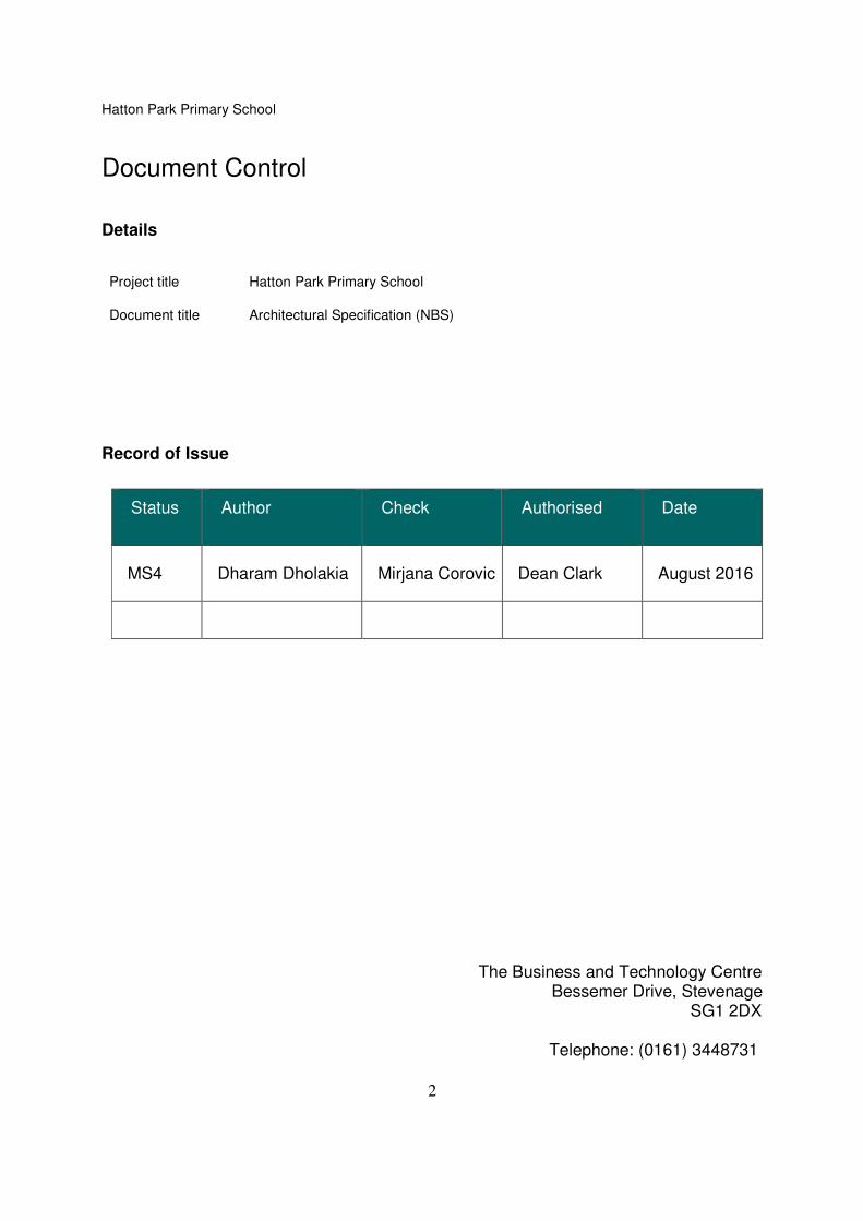
Document Control
Details
Project title Hatton Park Primary School
Document title Architectural Specification (NBS)
Record of Issue
Status Author Check Authorised Date
MS4 Dharam Dholakia Mirjana Corovic Dean Clark August 2016
The Business and Technology Centre
Bessemer Drive, Stevenage SG1 2DX
Telephone: (0161) 3448731
Hatton Park Primary School
3
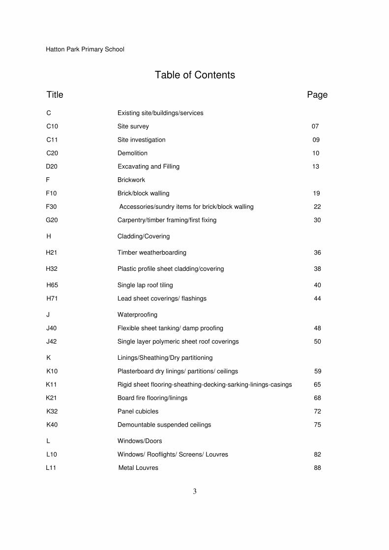
Table of Contents
Title Page
C Existing site/buildings/services
C10 Site survey 07
C11 Site investigation 09
C20 Demolition 10
D20 Excavating and Filling 13
F Brickwork
F10 Brick/block walling 19
F30 Accessories/sundry items for brick/block walling 22
G20 Carpentry/timber framing/first fixing 30
H Cladding/Covering
H21 Timber weatherboarding 36
H32 Plastic profile sheet cladding/covering 38
H65 Single lap roof tiling 40
H71 Lead sheet coverings/ flashings 44
J Waterproofing
J40 Flexible sheet tanking/ damp proofing 48
J42 Single layer polymeric sheet roof coverings 50
K Linings/Sheathing/Dry partitioning
K10 Plasterboard dry linings/ partitions/ ceilings 59
K11 Rigid sheet flooring-sheathing-decking-sarking-linings-casings 65
K21 Board fire flooring/linings 68
K32 Panel cubicles 72
K40 Demountable suspended ceilings 75
L Windows/Doors
L10 Windows/ Rooflights/ Screens/ Louvres 82
L11 Metal Louvres 88
Hatton Park Primary School
4
L20 Doors/ shutters/ hatches 89
L30 Freestanding Safety Guardrail system 95
L40 General glazing 97
M Surface finishes
M10 Cement based levelling/ wearing screeds 99
M20 Plastered/ Rendered coatings 102
M40 Ceramic tiling 106
M50 Vinyl/ carpet tiling/ sheeting 109
M60 Painting/clear finishing 114
M61 Intumescent coatings for fire protection of steelwork 120
N Furniture/Equipment
N10 General fixtures/ furnishings/ equipment 122
N13 Sanitary appliances and fittings 126
N14 General signage systems 131
N15 Fire and safety signage systems 133
P Building fabric sundries
P10 Sundry insulation/ proofing work 134
P12 Fire stopping systems 136
P20 Unframed isolated trims/ skirtings/ sundry items 139
P21 Door/ window ironmongery 141
P30 Trenches, pipeways and pits for buried engineering services 142
P31 Holes, chases, covers and supports for services 144
R Disposal systems
R10 Rainwater drainage systems 146
R11 Above ground foul drainage systems 149
Z Building fabric reference specification
Z10 Purpose made joinery 153
Z12 Preservative/ fire retardant treatment 155
Z20 Fixings and adhesives 156
Z21 Mortars 158

Hatton Park Primary School
5
Z22 Sealants 160 Z31 Powder coatings 161
Rev. A - Section H21/clause130 updated Section H65/clause120 updated Section J42/clause 341B deleted Section K10/clause 245 updated Section M60/clause 113 updated Section M60/clause 162 added Section N10/clause 240 updated Section P10/clause 120 updated Section P10/clause 320 updated Section P12/clause 150 added
Hatton Park Primary School
6
00
00 Materials and workmanship generally
10 MATERIALS AND WORKMANSHIP GENERALLY • Materials and workmanship are to be of the best quality and standards, and as stated on the drawings, or in these preambles. • Any discrepancies between these preambles and the drawings should be identified to the Contract Administrator immediately. • All materials are to be to the latest British Standards where applicable. • Materials shall be tested in accordance with relevant British Standard when requested to do so by the Contract Administrator, or as stated in these preambles. • All proprietary items are to be fixed completely in accordance with the manufacturer's or supplier's instructions and/or recommendations. • Contractors are to ensure that all materials specified are available within the contract period. Any deviations due to anticipated problems must be stated on submission of tender.
Hatton Park Primary School
7
C10 Site Survey
To be read with Preliminaries/ General conditions.
GENERAL
110 EXTENT OF SURVEY • Location: Refer to drawing 17351ea-01; 17351ea-02; 17351ea-03; 17351ea-04; 17351UG-01;
17351UG-02 • Scope: Topographical Survey & Utility Location Survey; site levels; drainage. • Topographical Survey completed by Survey Solutions • Objectives: Site and building features.
130 BACKGROUND INFORMATION SOURCES • Subject: Record information. . • Source: Health and safety file. • Contact: . .
140 ACCESS TO THE SITE FOR SURVEYING • Details: • Contact:
150 BENCH MARKS • Unrecorded bench marks and other survey information: Give notice when found and notify Ordnance Survey.
160 UNFORESEEN HAZARDS • Unrecorded hazards and hazardous materials: Give notice when found. Do not disturb.
170 SURVEY INSTRUMENTS • Equipment calibration: In accordance with manufacturer's recommendations. • Site use calibration: To BS 7334. • Calibration: Use only persons accredited by the United Kingdom Accreditation Service (UKAS). • Calibration compliance: Submit evidence prior to use.
180 WORKMANSHIP • Operatives: Appropriately skilled and experienced for the type of work. • Qualifications of operatives: Submit evidence prior to commencement.
190 PHOTOGRAPHS • Digital photographs: Required. - Format: JPEG. - Effective pixels: 5 million. - Presentation: On CD. - Index and thumbnail images: Required. • Subjects: Locating views and close ups of all points of interest.
Hatton Park Primary School
8
SURVEY WORKS
220 SITE SURVEY • Examine all available information, carry out a survey and submit a report to include the following: • Area to be surveyed: as 110 • Features to be included: ground/soil levels relative to floor levels prior to commencement. . • Specific requirements as to method: see above.
240 SETTING OUT/ CONTROL SURVEY • Examine all available information, carry out a survey and submit a report to include the following: • Area to be surveyed: The School Site. . • Features to be included: buildings and ground/soil levels relative to floor levels prior to commencement. • Specific requirements as to method: None.
260 TOPOGRAPHIC SURVEY • Examine all available information, carry out a survey and submit a report to include the following: • Area to be surveyed: The School Site. • Features to be included: services positions; site levels; drainage cover positions with invert levels buried services; tree positions with canopy sizes; Building Survey - floor plans with the levels; sections; and external elevations/sections. • Specific requirements as to method: None.
300 SERVICES SURVEY • Examine all available information, carry out a survey and submit a report to include the following: • Area to be surveyed: Site at Hatton Park Primary School • Features to be included: buried services. . • Specific requirements as to method: None.
310 GROUND PENETRATING RADAR SURVEY • Examine all available information, carry out a survey and submit a report to include the following: Site at Hatton Park Primary School • Area to be surveyed: • Features to be included: Buried Services. • Specific requirements as to method: None.
COMPLETION
910 DOCUMENTATION • Survey report: Survey Solutions Topographical Survey. - Contents: Record Drawings. - Copies:. • Format: Contractor's choice. • Computer based electronic files: Submit. Electronic file formats: Drawings and sketches: Autocad version.
Hatton Park Primary School
9
C11 Site Investigation
To be read with Preliminaries/ General conditions.
GENERAL REQUIREMENTS
130A BACKGROUND INFORMATION SOURCES • Subject: Ground Investigation Report Number 14456SI dated May 2016 by RSA Geotechnics
LTD. • Included in Appendices.
140 ACCESS TO THE SITE • Details: • Contact:
150 PUBLIC SAFETY • Protection of the public and occupiers of adjoining property: Erect temporary fences, hoardings, fans, footpaths, warning lights, etc. before starting work. • Means of escape from adjoining property in the event of fire: Maintain for the duration of the Works. • Specific hazards which may be encountered: Refer to drawings.
160A PROTECTION • Excavations and boreholes: Support sides and keep free from ground and surface water.
Hatton Park Primary School
10
C20 Demolition
To be read with Preliminaries/General conditions
GENERAL REQUIREMENTS
120 EXTENT OF DEMOLITION • General: Subject to retention requirements specified elsewhere demolish structures down to below ground floor level.
140 BENCH MARKS • Unrecorded bench marks and other survey information: Give notice when found. - Do not remove or destroy.
SERVICES AFFECTED BY DEMOLITION
210 SERVICES REGULATIONS • Work carried out to or which affects new or existing services: Carry out in accordance with the Byelaws or Regulations of the relevant Statutory Authority.
220 LOCATION OF SERVICES • Services affected by the Works: Locate and mark positions. • Mains services: Arrange with the appropriate authorities for location and marking of positions. • Standard: In accordance with National Joint Utilities Group (NJUG) 'Guidelines on the positioning and colour coding of utilities' apparatus'.
230 DISCONNECTION - ARRANGED BY CONTRACTOR • General: Arrange with the appropriate authorities for disconnection of services and removal of fittings and equipment prior to starting demolition.
240 DISCONNECTION OF DRAINS • General: Locate disconnect and seal disused drain connections. • Sealing: Within the site and permanent.
250 DRAINS IN USE • General: Protect drains, manholes, inspection chambers, gullies, vent pipes and fittings still in use and ensure that they are kept free of debris. • Damage: Make good damage arising from demolition work. Leave clean and in working order at completion.
260 BYPASS CONNECTIONS • General: Provide as necessary to maintain continuity of services to occupied areas of the same and adjoining properties. • Minimum notice to occupiers: 72 hours if shutdown is necessary during changeover.
270 SERVICES WHICH ARE TO REMAIN • Damage: Give notice and notify service authority or owner of damage arising from the execution of the works. • Repairs: Complete as directed, and to the satisfaction of the service authority or owner.
Hatton Park Primary School
11
310 WORKMANSHIP • Standard: Demolish structures in accordance with BS 6187. • Operatives: - Appropriately skilled and experienced for the type of work. - Holding or in training to obtain relevant CITB Certificates of Competence. • Site staff responsible for supervision and control of work: Experienced in the assessment of risks involved and methods of demolition to be used.
320 GAS OR VAPOUR RISKS • Precautions: Prevent fire or explosion caused by gas or vapour.
330 DUST CONTROL • Method: Reduce by periodically spraying demolition works with an appropriate wetting agent.
340 HEALTH HAZARDS • Precautions: Protect site operatives and general public from hazards associated with vibration, dangerous fumes and dust arising during the course of the Works.
350 ADJOINING PROPERTY • Temporary support and protection: Provide. Maintain and alter as necessary as work progresses. • Damage: Minimize. Promptly repair. - Leave no unnecessary or unstable projections. - Make good to ensure safety, stability, weather protection and security. • Support to foundations: Do not disturb. • Defects: Report when exposed or becoming apparent.
370 PARTLY DEMOLISHED STRUCTURES • General: Leave in a stable condition, with adequate temporary support at each stage to prevent risk of uncontrolled collapse. Keep safe outside working hours. • Temporary works: Prevent debris from overloading. • Unauthorised persons: Prevent access.
380 DANGEROUS OPENINGS • General: Illuminate and protect. Keep safe outside working hours.
390 ASBESTOS CONTAINING MATERIALS • General: These are known to be present in the structures to be demolished in the following locations: The CA shall provide details. • Removal: By a Contractor licensed by the Health and Safety Executive and prior to other works starting in these locations.
391 ASBESTOS CONTAINING MATERIALS • Discovery: Give notice immediately of suspected asbestos containing materials discovered during demolition work. Avoid disturbing such materials. • Methods for safe removal. Submit details.
410 UNFORESEEN HAZARDS • Unrecorded voids, tanks, chemicals, etc. discovered during demolition: Give notice. • Methods for safe removal, filling, etc: Submit details.
Hatton Park Primary School
12
420 OPEN BASEMENTS, ETC • Temporary support: Leave adequate buttress walls or provide temporary support to basement retaining walls up to ground level. • Safety: Make remaining sections of retaining and buttress walls safe and secure. • Water movement: Make holes in basement floors to allow water drainage or penetration (depending on water table). Provide a hole for every 10 m², not less than 600 mm in diameter.
440 SITE CONDITION AT COMPLETION • Debris: Clear away and leave the site in a tidy condition. Other requirements: Remove all hardstandings.
441 SITE LEVELS AT COMPLETION • Levels: Grade the site to follow the levels of adjacent areas.
MATERIALS ARISING
510 CONTRACTOR'S PROPERTY • Components and materials arising from the demolition work: Property of the Contractor except where otherwise provided. - Remove from site as work proceeds.
511 EMPLOYER'S PROPERTY • Components and materials to remain the property of the Employer: Climbing frame to existing Hall. • Protection: - Maintain until these items are removed by the Employer, reused in the Works or the end of the Contract. • Special requirements: Provide secure on-site storage for climbing frame to facilitate demolition of existing building.
Hatton Park Primary School
13
D20 Excavating and filling
To be read with Preliminaries/General conditions.
GENERALY/THE SITE
110 SITE INVESTIGATION • Report:
112 SITE INVESTIGATION REPORT • See Ground Engineering Report.
145 VARIATIONS IN GROUND WATER LEVEL • Give notice: If levels encountered are significantly different from levels in the site investigation report or previously measured.
150 EXISTING SERVICES/ FEATURES/ STRUCTURES • Services:. • Site features to be retained: • Structures:
CLEARANCE/EXCAVATING
164 TREE ROOTS • Protected area: Do not cut roots within an area which is the larger of: - The branch spread of the tree. - An area with a radius of half the tree's height, measured from the trunk. • Excavation in protected area: - Method: Contractor's choice . - Backfill as soon as possible or temporarily line with polyethylene sheet to reduce evaporation. • Outside protected area: Give notice of roots exceeding 25 mm and do not cut without approval. • Cutting: - Make clean smooth cuts with no ragged edges. - Pare cut surfaces smooth with a sharp knife. - Treatment of cut roots: Not required . • Backfill: As dug material .
170 REMOVING TREES, SHRUBS AND HEDGES • Identification: Clearly mark trees to be removed. • Safety: Comply with HSE/ Arboriculture and Forestry Advisory Group Safety Guides. • Felling: Cut down and grub up roots of shrubs and smaller trees. Fell larger trees as close to the ground as possible and remove stumps mechanically to a minimum depth of 300 mm below ground level . • Work near retained trees: Take down trees carefully in small sections to avoid damage to adjacent trees that are to be retained, where tree canopies overlap and in confined spaces generally. • Stumps: Obtain approval before removing stumps by winching and do not use other trees as supports or anchors.
181 SITE CLEARANCE • Timing: Before topsoil stripping, if any. • General: Clear site of rubbish, debris and vegetation. Do not compact topsoil. • Large roots: Grub up and dispose of without undue disturbance of soil and adjacent areas.
Hatton Park Primary School
14
• Chipping and shredding: Permitted . • Treatment: Apply a suitable nonresidual herbicide to areas to receive landscape planting in accordance with BS 7370-2 clause 4.6 .
220 STRIPPING TOPSOIL • General: Before beginning general excavation or filling, strip topsoil from areas where there will b regrading, buildings, pavings/ roads and other areas shown on drawings. • Depth: - Remove to an average depth of 300 mm and keep separate from excavated subsoil. - Give notice where the depth of topsoil is difficult to determine. • Handling: Handle topsoil for reuse or sale in accordance with clause 225. • Around trees: Do not remove topsoil from below the spread of trees to be retained.
221 TREATING TOPSOIL • Treatment: Apply a suitable translocated nonresidual herbicide. • Timing: Not less than two weeks before excavating topsoil.
225 HANDLING TOPSOIL • Aggressive weeds: - Species: Included in the Weeds Act, section 2 or the Wildlife and Countryside Act, Schedule 9 part II. - Give notice: Obtain instructions before moving topsoil. • Earthmoving equipment: Select and use to minimize disturbance, trafficking and compaction. • Contamination: Do not mix topsoil with: - Subsoil, stone, hardcore, rubbish or material from demolition work. - Oil, fuel, cement or other substances harmful to plant growth. - Other grades of topsoil. • Multiple handling: Keep to a minimum. Use topsoil immediately after stripping. • Wet conditions: Handle topsoil in the driest condition possible. Do not handle during or after heavy rainfall or when it is wetter than the plastic limit as defined by BS 3882, Annex N2.
240 ADJACENT EXCAVATIONS • Proximity: Where an excavation encroaches below a line drawn at an angle from the nearest formation level of another higher excavation, the lower excavation, all work within it and backfilling thereto must be completed before the higher excavation is made. • Angle of line from horizontal: 45° .
250 PERMISSIBLE DEVIATIONS FROM FORMATION LEVELS • Beneath mass concrete foundations: ±25 mm. • Beneath ground bearing slabs and r.c. foundations: ±15 mm. • Embankments and cuttings: ±50 mm. • Ground abutting external walls: ±50 mm, but such as to ensure that finished level is not less than 150 mm below dpc.
255 ACCURACY - LINEAR DIMENSIONS • Permissible deviations from linear dimensions generally: ±15 mm .
260 INSPECTING FORMATIONS • Give notice: Make advance arrangements for inspection of formations for foundations and filling formations . • Preparation: Just before inspection remove the last 150 mm of excavation. Trim to required profiles and levels, and remove loose material. • Seal: Within 4 hours of inspection, seal formations with as directed .
Hatton Park Primary School
15
270 FOUNDATIONS GENERALLY • Give notice if: - A natural bearing formation of undisturbed subsoil is not obtained at the depth shown on the drawings. - The formation contains soft or hard spots or highly variable material.
280 TRENCH FILL FOUNDATIONS • Excavation: Form trench down to formation in one operation. • Safety: Prepare formation from ground level. • Inspection of formations: Give notice four working days before commencing excavation. • Shoring: Where inspection of formation is required, provide localised shoring to suit ground conditions. • Concrete fill: Place concrete immediately after inspection and no more than four hours after exposing the formation.
290 FOUNDATIONS IN MADE UP GROUND • Depth: Excavate down to a natural formation of undisturbed subsoil. • Discrepancy: Give notice if this is greater or less than depth given.
310 UNSTABLE GROUND • Generally: Ensure that the excavation remains stable at all times. • Give notice: Without delay if any newly excavated faces are too unstable to allow earthwork support to be inserted. • Take action: If instability is likely to affect adjacent structures or roadways, take appropriate emergency action.
320 RECORDED FEATURES • Recorded foundations, beds, drains, manholes, etc: Break out and seal drain ends. • Contaminated earth: Remove and disinfect as required by local authority.
330 UNRECORDED FEATURES • Give notice: If unrecorded foundations, beds, voids, basements, filling, tanks, pipes, cables, drains, manholes, watercourses, ditches, etc. not shown on the drawings are encountered.
350 EXISTING WATERCOURSES • Diverted watercourses which are to be filled: Before filling, remove vegetable growths and soft deposits.
370 UNDERGROUND STRUCTURES IN LANDSCAPE AREAS • Generally: Remove walls, roads, foundations, disused services, drains, manholes and the like to minimum depth. • Minimum depth below finished levels: - Grass, ground cover and perennial planting: 500 mm. - Shrub planting: 750 mm. - Within 2 m of tree planting: 1000 mm. • Walls and slabs remaining: In every 10 m² of wall or slab, make a drainage hole at least 600 mm diameter.
DISPOSAL OF MATERIALS
410 EXCAVATED TOPSOIL STORAGE • Storage: Stockpile in temporary storage heaps locations to be agreed on site .
420 TOPSOIL STORAGE HEAPS • Location: To be agreed on site . • Height (maximum): 1 m .
Hatton Park Primary School
16
• Protection: - Do not place any other material on top of storage heaps. - Do not allow construction plant to pass over storage heaps. - Prevent compaction and contamination.
TOPSOIL STORAGE HEAP TREATMENT • Treatment: Apply a suitable herbicide at appropriate times to prevent seeding of weeds .
441 SURPLUS SUBSOIL • Excavated material: Stockpile in temporary storage heaps. • Retained material: Spread and level surplus subsoil on site. - Locations: As directed by the CA . - Protected areas: Do not raise soil level within root spread of trees that are to be retained. • Remaining material: Remove from site.
450 WATER • Generally: Keep all excavations free from water until: - Formations are covered. - Below ground construction are completed. - Basement structures and retaining walls are able to resist leakage, water pressure and flotation. • Drainage: Form surfaces of excavations and fill to provide adequate falls. • Removal of water: Provide temporary drains, sumps and pumping as necessary. Do not pollute watercourses with silt laden water.
454 GROUND WATER LEVEL/ RUNNING WATER • Give notice: If it is considered that the excavations are below the water table. • Springs/ Running water: Give notice immediately if encountered.
457 PUMPING • General: Do not disturb excavated faces or stability of adjacent ground or structures. • Pumped water: Discharge without flooding the site or adjoining property. • Sumps: Construct clear of excavations. Fill on completion. - Locations: Submit proposals.
FILLING
500 PROPOSED FILL MATERIALS • Details: Submit full details of proposed fill materials to demonstrate compliance with specification, including: - Type and source of imported fill. - Proposals for processing and reuse of material excavated on site. - Test reports as required elsewhere. • Timing: At least 14 days before starting filling .
510 HAZARDOUS, AGGRESSIVE OR UNSTABLE MATERIALS • General: Do not use fill materials which would, either in themselves or in combination with other materials or ground water, give rise to a health hazard, damage to building structures or instability in the filling, including material that is: - Frozen or containing ice. - Organic. - Contaminated or noxious. - Susceptible to spontaneous combustion. - Likely to erode or decay and cause voids. - With excessive moisture content, slurry, mud or from marshes or bogs.
Hatton Park Primary School
17
- Clay of liquid limit exceeding 80 and/or plasticity index exceeding 55. - Unacceptable, class U2 as defined in the Highways Agency 'Specification for highway works', clause 601.
520 FROST SUSCEPTIBILITY • General: Except as allowed below, fill must be non frost-susceptible as defined in Highways Agency 'Specification for Highway Works', clause 801.17. • Test reports: If the following fill materials are proposed, submit a laboratory report confirming they are non frost- susceptible: - Fine grained soil with a plasticity index less than 20%. - Coarse grained soil or crushed granite with more than 10% retained on a 0.063 mm sieve. - Crushed chalk. - Crushed limestone fill with average saturation moisture content in excess of 3%. - Burnt colliery shale. • Frost-susceptible fill: May only be used within the external walls of buildings below spaces that will be heated. Protect from frost during construction.
530 PLACING FILL • Excavations and areas to be filled: Free from loose soil, rubbish and standing water. • Freezing conditions: Do not place fill on frozen surfaces. Remove material affected by frost. Replace and recompact if not damaged after thawing. • Adjacent structures, membranes and buried services: - Do not overload, destabilise or damage. - Submit proposals for temporary support necessary to ensure stability during filling. - Allow 14 days (minimum) before backfilling against in situ concrete structures. • Layers: Place so that only one type of material occurs in each layer. • Earthmoving equipment: Vary route to avoid rutting.
535 COMPACTION • General: Compact fill as soon as possible after placing. • After compaction: Surface of each layer must be well closed, showing no movement under compaction plant, and without cracks, holes, ridges, loose material and the like. • Defective areas: Remove and recompact to full thickness of layer using new material.
540 BENCHING IN FILL • Adjacent areas: If, during filling the difference in level between adjacent areas of filling exceeds 600 mm, cut into edge of higher filling to form benches 600 mm minimum width and height equivalent to depth of a layer of compacted filling. • New filling: Spread and compact to ensure maximum continuity with previous filling.
610 COMPACTED FILLING FOR LANDSCAPE AREAS • Fill: Material capable of compaction by light earthmoving plant. • Filling: Layers not more than 200 mm thick. Lightly compact each layer to produce a stable soil structure.
615 LOOSE TIP FILLING FOR LANDSCAPE AREAS • Filling: Do not firm, consolidate or compact when laying. Tip and grade to approximate levels in one operation with minimum of trafficking by plant.
650 PROTECTION OF COMPACTED FILLING • Temporary protective filling: Before allowing construction traffic, raise level of compacted cohesive soil filling at least 150 mm above formation level using properly compacted temporary filling. • Removal: Remove temporary protective filling from site before permanent construction.
Hatton Park Primary School
18
700 BACKFILLING AROUND FOUNDATIONS • Under oversite concrete and pavings: Hardcore as clause 710. • Under grassed or soil areas: Material excavated from the trench, laid and compacted in 300 mm maximum layers.
710 HARDCORE FILLING • Fill: Granular material, free from excessive dust, well graded, all pieces less than 75 mm in any direction, minimum 10% fines value of 50 kN when tested in a soaked condition to BS 812-111, and in any one layer only one of the following: - Crushed rock (other than argillaceous rock) or quarry waste with not more binding material than is required to help hold the stone together. - Crushed concrete, crushed brick or tile, free from plaster, timber and metal. - Crushed non-expansive slag. - Gravel or hoggin with not more clay content than is required to bind the material together, and with no large lumps of clay. - Well-burned non-plastic colliery shale. - Natural gravel. - Natural sand. • Filling: Spread and level in 150 mm maximum layers. Thoroughly compact each layer.
Hatton Park Primary School
19
F10 Brick/ block walling
To be read with Preliminaries/ General conditions.
TYPES OF WALLING
110 CLAY FACING BRICKWORK ABOVE GROUND TO EXTERNAL WALLS • Bricks: To BS 3921. - Manufacturer: Camtech Building Products Ltd, 5 The Sidings, Station Road, Shepreth, Cambridgeshire, SG8 6PZ. Tel: 01763 262006. Fax: 01763 268359. Product reference: DR Buff Handmade. - Special shapes: As shown on drawings. • Mortar: As section Z21. - Standard: To BS 4721. - Mix: 1:1:6 cement:lime:sand. - Additional requirements: Submit colour samples for approval . • Bond: Half lap stretcher. • Joints: Bucket handle. • Features: None.
112 CLAY FACING BRICKWORK PLINTH STRETCHER BANDS TO FACING BRICKWORK • Bricks: To BS 3921. - Manufacturer: Camtech Building Products Ltd, 5 The Sidings, Station Road, Shepreth, Cambridgeshire, SG8 6PZ. Tel: 01763 262006. Fax: 01763 268359. Product reference: Original Blue Stock. - Special shapes: As shown on drawings. • Mortar: As section Z21. - Standard: To BS 4721. - Mix: 1:1:6 cement:lime:sand. - Additional requirements: Submit colour samples for approval . • Bond: Brick-on-end. • Joints: Bucket handle. • Features: None.
310 CLAY COMMON BRICKWORK BELOW GROUND • Bricks: To BS 3921. - Average compressive strength (minimum): 21 N.mm². - Durability designation: FL. - Water absorption to BS 3921 Appendix E: Less than 20%. - Configuration: Frogged. • Mortar: As section Z21. - Standard: To BS 4721. - Mix: Group 3 as clause 460 with sulphate resisting cement. - Additional requirements: None. • Bond: Half lap stretcher.
350 CONCRETE COMMON BLOCKWORK GENERALLY • Blocks: To BS 6073-1. - Manufacturer: Hanson Conbloc Fenlite Solid, Lignacite or similar approved. Product reference: as above. - Type: Solid. - Average compressive strength (minimum): 7 N/mm². - Thermal conductivity (maximum) certified by UKAS accredited laboratory at not
Hatton Park Primary School
20
applicable moisture content to BS EN 12664: Not applicable. - Work sizes (length x height x thickness): 440 x 215 x 140. - Special shapes: Coursing blocks. • Mortar: As section Z21. - Standard: Not applicable. - Mix: 1:0.25:3 cement:lime:sand 12N/mm2 (mortar class12) below DPC and 1:1:6 cement:lime:sand 4N/mm2(mortar class 4) above DPC.. - Additional requirements: Durability: Freeze/ thaw resistance: Frost resistant below ground level. • Bond: Half lap stretcher. NB. Block weight not to exceed 18kg- use coursing blocks to avoid heavy weight blocks.
380A ENGINEERING BRICKWORK BELOW GROUND • Engineering bricks: To BS 3921. - Class B. • Mortar: As section Z21. - Standard: To BS 4721. - Mix: 1:3 cement:sand. - Additional requirements: None. • Bond: Half lap stretcher. • Joints: Flush.
TESTING
410 COMPRESSIVE STRENGTH OF MORTAR FOR EACH WALLING TYPE • Testing authority: A UKAS Accredited laboratory. • Test method: BS 5628-1 Appendix A1 and BS 4551-1. • Preliminary tests procedure: As follows: - Specimens: Number of specimens: 6. Type: 100 mm cubes. Preparation: At least six weeks before walling commences. - Specimen testing: Half of specimens at 7 days. Remainder at 28 days. Retarded mixes: Extend curing periods to include retardation period. - Response to result: If mean compressive strength at 28 days is not within the range given below repeat tests with more suitable sand or next higher designation of mortar. • Site tests procedure: As follows. - Number of specimens: Six per 150m² of walling or per storey whichever the more frequent. - Specimen types: As preliminary test, but prepared during construction. - Specimen testing: Half of specimens at 7 days. Remainder at 28 days. Retarded mixes: Extend curing periods to include retardation period. • Required test mean compressive strength at 28 days (N/mm²): To be within the following range:
Walling type Preliminary tests Site tests Min. Max. Min. Max. N/mm² N/mm² N/mm² N/mm² (MPa) (MPa) (MPa) (MPa) F10/110 3.6 3.6 2.5 2.5
• Results: Submit.
415 FRESH MORTAR CEMENT CONTENT • Test method: BREMORTEST in accordance with Building Research Establishment Information Paper 8/89 . • Test specimens: Test mortar for the following wall types: F10/ 110, 112 . • Results: Submit.
Hatton Park Primary School
21
WORKMANSHIP GENERALLY
430 CONDITIONING OF CLAY AND CALCIUM SILICATE BRICKS • Bricks delivered warm from manufacturing process: Do not use until cold. • Absorbent bricks in warm weather: Wet to reduce suction. Do not soak.
440 CONDITIONING OF CONCRETE BRICKS/ BLOCKS • Autoclaved concrete bricks/ blocks delivered warm from manufacturing process: Do not use. • Age of nonautoclaved concrete bricks/ blocks: Do not use until at least four weeks old. • Avoidance of suction in concrete bricks/ blocks: Do not wet. - Use of water retaining mortar admixture: Submit details.
460 MORTAR GROUPS • Mix proportions: For a specified group select a mix design from the following: __________________________________________________________________________ Group 1 2 3 4 __________________________________________________________________________ PC*:lime:sand with or without air entraining additive 1:0-0.25:3 1:0.5-4.5 1:1:5-6 1:2:8-9 __________________________________________________________________________ Masonry cement:sand containing PC* and lime in approx ratio 1:1, and an air entraining additive - 1:3 1:3.5-4 1:4.5 __________________________________________________________________________ Masonry cement:sand containing PC* and inorganic materials other than lime and air entraining additive - 1:2.5-3.5 1:4-5 1:5.5-6.5 __________________________________________________________________________ PC*:sand and air entraining additive 1:3 1:3-4 1:5-6 1:7-8 __________________________________________________________________________ PC* = Portland cement
• Batching: Mix proportions by volume. • Mortar type: Continuous throughout any one type of masonry work.
500 LAYING GENERALLY • Mortar joints: Fill vertical joints. Lay bricks, solid and cellular blocks on a full bed. • Bond where not specified: Half lap stretcher. • Vertical joints in facework: Even widths. Plumb at every fifth cross joint.
520 ACCURACY • Courses: Level and true to line. • Faces, angles and features: Plumb. • Permissible deviations: - Position in plan of any point in relation to the specified building reference line and/ or point at the same level ± 10 mm. - Straightness in any 5 m length ± 5 mm. - Verticality up to 3 m height ± 10 mm. - Verticality up to 7 m height ± 14 mm. - Overall thickness of walls ± 10 mm. - Level of bed joints up to 5 m (brick masonry) ± 11 mm. - Level of bed joints up to 5 m
Hatton Park Primary School
22
(block masonry) ± 13 mm.
535 HEIGHT OF LIFTS IN WALLING USING CEMENT GAUGED OR HYDRAULIC LIME MORTAR • Quoins and advance work: Rack back. • Lift height (maximum): 1.2 m above any other part of work at any time. • Daily lift height (maximum): 1.5 m for any one leaf.
545 LEVELLING OF SEPARATE LEAVES • Locations for equal levelling of cavity wall leaves: As follows: - Every course containing vertical twist type ties or other rigid ties. - Every third tie course for double triangle/ butterfly ties. - Courses in which lintels are to be bedded.
560 COURSING BRICKWORK • Gauge: Four brick courses including bed joints to 300 mm.
580 LAYING FROGGED BRICKS • Single frogged bricks: Frog uppermost. • Double frogged bricks: Larger frog uppermost. • Frog cavity: Fill with mortar.
585 LAYING CELLULAR BRICKS • Orientation: Cavities downward.
595 LINTELS • Bearing: Ensure full length masonry units occur immediately under lintel ends.
610 SUPPORT OF EXISTING WORK • Joint above inserted lintel or masonry: Fully consolidated with semidry mortar to support existing structure.
615 BRICKWORK TO RECEIVE ASPHALT DPC • Substrate: Mortar bed finished flush, smooth and level.
620 BLOCK BONDING NEW WALLS TO EXISTING • Pocket requirements: Formed as follows: - Width: Full thickness of new wall. - Depth (minimum): 100 mm. - Vertical spacing: Brick to brick: 4 courses high at 8 course centres. Block to block: Every other course. • Pocket joints: Fully filled with mortar.
635 JOINTING • Profile: Consistent in appearance.
645 ACCESSIBLE JOINTS NOT EXPOSED TO VIEW • Jointing: Struck flush as work proceeds.
665 POINTING TO FACING BRICKWORK ABOVE GROUND • Joint preparation: Remove debris. Dampen surface. • Mortar: As section Z21. - Standard: To BS 4721. - Mix: 1:1:6 cement:lime:sand. - Additional requirements: Coloured mortar to match bricks. • Profile: Bucket handle.
Hatton Park Primary School
23
671 FIRE STOPPING • Avoidance of fire and smoked penetration: Fit tightly between cavity barriers and masonry. Leave no gaps. • General: Do not use frozen materials or lay on frozen surfaces. • Air temperature requirements: Do not lay bricks/ blocks: - In cement gauged mortars when at or below 3°C and falling or unless it is at least 1°C and rising. - In hydraulic lime:sand mortars when at or below 5°C and falling or below 3°C and rising. - In thin joint mortar glue when outside the limits set by the mortar manufacturer. • Temperature of walling during curing: Above freezing until hardened. • Newly erected walling: Protect at all times from: - Rain and snow. - Drying out too rapidly in hot conditions and in drying winds.
ADDITIONAL REQUIREMENTS FOR FACEWORK
710 THE TERM FACEWORK • Definition: Applicable in this specification to brick/ block walling finished fair. - Painted facework: The only requirement to be waived is that relating to colour.
740 FINISHED MASONRY WORK REFERENCE PANELS • General: Before proceeding to construct the following walling types, construct panels as specified Give notice when panels are dry. • Selection of masonry units: Randomly to BS 3921 clause 9 . • Panel types: - Walling type: F10/110 . Location: Good natural light with a viewing distance of 3 m . Size: 1.5 x 1.5 m . Other requirements: To include brick-on-end banding. Remove on completion of project .
750 COLOUR CONSISTENCY OF MASONRY UNITS • Colour range: Submit proposals of methods taken to ensure that units are of consistent and even appearance within deliveries. • Conformity: Check each delivery for consistency of appearance with previous deliveries and with approved reference panels; do not use if variation is excessive. • Finished work: Free from patches, horizontal stripes and racking back marks.
760 APPEARANCE • Brick/ block selection: Do not use units with damaged faces or arrises. • Cut masonry units: Where cut faces or edges are exposed cut with table masonry saw. • Quality control: Lay masonry units to match relevant reference panels. - Setting out: To produce satisfactory junctions and joints with built-in elements and components. - Coursing: Evenly spaced using gauge rods. • Lifts: Complete in one operation. • Methods of protecting facework: Submit proposals.
780 GROUND LEVEL • Commencement of facework: Not less than 150 mm below finished level of adjoining ground or external works level.
790 PUTLOG SCAFFOLDING • Use: Not permitted in facework.
830 CLEANLINESS • Facework: Keep clean.

Hatton Park Primary School
24
• Mortar on facework: Allow to dry before removing with stiff bristled brush. • Removal of marks and stains: Rubbing not permitted.
Hatton Park Primary School
25
F30 Accessories/ sundry items for brick/ block walling
To be read with Preliminaries/ General conditions.
CAVITIES
110 CONCRETE FILL TO BASE OF CAVITY • Concrete generally: To BS EN 206-1 and BS 8500-2. - Designated concrete: GEN 1 . Workability: High. • Extent: Maintain 75 mm between top of fill and external ground level and a minimum of 225 mm between top of fill and ground level dpc. • Placement: Compact to eliminate voids.
120 CLEANLINESS • Cavity base and faces, ties, insulation and exposed dpcs: Free from mortar and debris.
132 PERPEND JOINT PLASTICS WEEP HOLES • Manufacturer: Rytons Building Products Ltd. Design House, Kettering Business Park, Kettering, Northamptonshire. NN15 6NL. Tel: 01536 511874. Fax: 01536 310455 . - Product reference: Weephole Ducts 107x75x10mm . • Locations: Through outer leaf at cavity trays, stepped dpcs and external openings. • Provision: At not greater than 1000 mm centres and not less than two over each opening.
150 PARTIAL FILL CAVITY INSULATION • Insulation: Kingspan Kooltherm K12
Manufacturer: Kingspan Insulation Ltd. Pembridge, Leominster, Herefordshire HR6 9LA Tel: 01544 388 601 Fax: 01544 388 888
Email: [email protected] Web: www.kingspaninsulation.co.uk • Material: Phenolic foam board • Face size (nominal length x width): 1.2x2.4m • Thickness (nominal): 100 mm . • Thermal conductivity: 0.020 W/mK . • Reaction to fire class: 0. • Additional requirements: None . • Placement: Continuous and free of mortar and debris.
171 VENTILATION DUCTS IN EXTERNAL WALLING • Manufacturer: Cavity Trays Limited, Administration Centre, Yeovil, Somerset, BA22 8HU. Tel: 01935 474769 . - Product reference: TAV Ventilator . • Placement: Across cavity, sloping away from inner leaf. Full mortar joints to seal cavity. • Protection from water penetration to inner leaf: Where barrier is not integral to duct, form stepped dpc cavity tray with stop ends above duct, extending 150 mm on each side.
Hatton Park Primary School
26
180 CAVITY CLOSERS FOR EXTERNAL WALLS
to all external window and door openings
Manufacturer: Kingspan Insulation Ltd. Pembridge, Leominster, Herefordshire HR6 9LA
Tel: 01544 388 601 Fax: 01544 388 888
Email: [email protected] Web: www.kingspaninsulation.co.uk
Accessories: Kingspan Kooltherm® Cavity Closer PLUS. Colour: Blue.
Jointing Strip: This connects two Kingspan Kooltherm® Cavity Closer sections, aligning them in a butt joint. The strip allows for opening sizes in excess of 2.4 m, and for the reduction of wastage through the use of off-cuts. Limited to one butt joint per side of the opening. Colour: Grey.
Fixing Tie: Kingspan Kooltherm® Cavity Closer PLUS to form openings. They cannot be used when two sections are joined back to back. The tie is designed with different angled ends which slot securely between the tee flanges at the back of the section and keys fully into the mortar bed joint of the outer masonry skin. They are moulded PVC-U supplied in packs of 150. Colour: White
REINFORCING/ FIXING ACCESSORIES
212 CAVITY WALL TIES FOR ALL CAVITY WALLS • Manufacturer: Ancon Building Products, President Way, President Park, Sheffield S4 7UR. Tel: 0114 275 5224 . - Product reference: Ancon STAIFIX-THOR HELICAL TIM6 with STAIFIX RED UNIVERSAL CLIP • Material/ finish: Austenitic stainless steel Grade 1.4301 (304) / Austenitic stainless steel Grade 1.4401 (316) . • Sizes: 250 mm for 150mm Cavity, 175mm for 80mm Cavity. An installation tool is required to hammer the tie into the timber frame/CLT panel. 228 FIXING TIES IN MASONRY CAVITY WALLS WITH CAVITY INSULATION • Embedment in mortar beds (minimum): 50 mm. • Placement: Sloping slightly downwards towards outer leaf, without bending. Drip centred in the cavity and pointing downwards. • Spacing: Staggered in alternate courses. - Horizontal centres: 750 mm . - Vertical centres: 450 mm . • Provision of additional ties: - One row to support lowest row of insulation batts. - Within 225 mm of reveals of unbonded openings. Spacing: In every course .
FLEXIBLE DAMP PROOF COURSES/ CAVITY TRAYS
330 DAMP PROOF COURSE - CO-POLYMER THERMOPLASTIC • Manufacturer: Visqueen Building Products, Zedcor Business Park, Bridge Street, Witney, Oxfordshire,OX8 6LJ Tel: 01993 776346 . - Product reference: Zedex CPT High Performance DPC .
370 PREFORMED CAVITY TRAYS • Manufacturer: Cavity Trays Limited, Administration Centre, Yeovil, Somerset, BA22 8HU. Tel: 01935 474769 . - Product references and locations: Type C Cavitray . • Placement: To provide a free draining and watertight installation.
Hatton Park Primary School
27
380 PREFORMED DPC/ CAVITY TRAY JUNCTION CLOAKS/ STOP ENDS • Manufacturer: Cavity Trays Limited, Administration Centre, Yeovil, Somerset, BA22 8HU. Tel: 01935 474769 . - Product references and locations: Type L . • Placement: To provide a free draining and watertight installation. Seal laps with dpcs and/ or cavity trays.
INSTALLATION OF DPCS/ CAVITY TRAYS
415 HORIZONTAL DPCS • Placement: In continuous lengths on full even bed of fresh mortar, with 100 mm laps at joints and full laps at angles. • Width: At least full width of leaf unless otherwise specified. Edges of dpc not covered with mortar or projecting into cavity. • Overlying construction: Immediately cover with full even bed of mortar to receive next masonry course. • Overall finished joint thickness: As close to normal as practicable.
425 GROUND LEVEL DPCS • Joint with damp proof membrane: Continuous and effectively sealed.
435 STEPPED DPCS IN EXTERNAL WALLS • External walls on sloping ground: Install dpcs not less than 150 mm above adjoining finished ground level.
445 SILL DPCS • Form and placement: In one piece and turned up at back when sill is in contact with inner leaf.
455 COPING/ CAPPING DPCS • Placement: Bed in one operation to ensure maximum bond between masonry units, mortar and dpc. • Dpcs crossing cavity: Provide rigid support to prevent sagging.
465 DPCS TO EXTERNAL WALLS • Overlaps and junctions: Seal with Adhesive/support recommended by DPC manufacturer .
485 CAVITY TRAYS OVER OPENINGS AND OTHER CAVITY BRIDGINGS • Length: To extend not less than 150 mm beyond ends of lintels/ bridgings.
515 DPC/ CAVITY TRAY LEADING EDGE IN FACEWORK - FLUSH • Treatment at face of masonry: Finish flush and clear of mortar at the following locations: Generally.
560 VERTICAL DPCS GENERALLY • Form: In one piece wherever possible. - Joints: Upper part overlapping lower not less then 100 mm.
570 JAMB DPCS AT OPENINGS • Joint with cavity tray/ lintel at head: Full underlap. • Joint with sill/ horizontal dpc at base: Full overlap. • Projection into cavity: Not less than 25 mm. • Relationship with frame: In full contact.
JOINTS
610 MOVEMENT JOINTS WITH SEALANT TO EXTERNAL FACING BRICKWORK • Joint preparation and sealant application: As section Z22.
Hatton Park Primary School
28
• Filler: Closed cell polyethylene foam . - Thickness: To match design width of joint. - Manufacturer: Fosroc Limited, Coleshill Road, Tamworth, Staffordshire B78 3TL. Tel: 01827 262222, Fax: 01827 262444 . Product reference: Hydrocell XL: Must be cross-linked with nominal 60kg/m3 density. Shall have a recovery of 98% after 50% compression and a compressive strength of 0.15N/mm2 (ASTM D3575).Shall have a water absorption of less than 0.05% by volume (ASTM D3575) and be resistant to weathering and chemical attack . - Placement: Build in as work proceeds with no projections into cavities and to correct depth to receive sealant system. • Sealant: - Designation: ISO 11600-F-25LM . - Manufacturer: Fosroc Limited, Coleshill Road, Tamworth, Staffordshire B78 3TL. Tel: 01827 262222, Fax: 01827 262444 . Product reference: Nitoseal MS100 . - Colour: To match adjoining brickwork .
615 MOVEMENT JOINTS WITHOUT SEALANT ELSEWHERE • Filler: - Thickness: To match design width of joint. - Manufacturer: Fosroc Limited, Coleshill Road, Tamworth, Staffordshire B78 3TL. Tel: 01827 262222, Fax: 01827 262444 . Product reference: Expandafoam . - Placement: Build in as work proceeds filling the joint but without projecting into cavities.
630 UNEXPOSED CONTRACTION JOINTS • Formation: Close butt as work proceeds.
650 POINTING IN FLASHINGS • Joint preparation: Free of debris and lightly wetted. • Pointing mortar: As for adjacent walling. • Placement: Fill joint and finish flush.
660 PINNING UP TO SOFFITS • Top joint of loadbearing walls: Fill and consolidate with mortar.
PROPRIETARY SILLS/ LINTELS/ COPINGS/ DRESSINGS
750 PREFABRICATED STEEL LINTELS • Standard: To BS 5977-2. • Manufacturer: IG Limited, Avondale Road, Cwmbran, Gwent, NP44 1XY. Tel: 01633 486460. Fax 01633 486465 . OR SIMILAR APPROVED - Product reference: L10, HD/L11 GALV. Refer to Lintel Schedule . • Material/ finish: Hot dipped galvanised steel, black polyester powder coated after fabrication . • Placement: Bed on mortar used for adjacent work with bearing of not less than 150 mm.
780 COPING SYSTEM • Manufacturer: Sotech Ltd. -Product reference: Optima Cassette Rainscreen System • Material/ finish: Aluminium. Polyester Powder Coated (PPC) to BS6496.

Hatton Park Primary School
29
MISCELLANEOUS ITEMS
840 OPENINGS FOR FRAMES • Formation: Use accurate, rigid templates to required size.
850 WALL PLATES • Placement: On full bed of mortar to correct horizontal level.
Hatton Park Primary School
30
G20 Carpentry/ timber framing/ first fixing
FOR CROSS LAMINATED TIMBER PANELS, REFER TO SUPPLIER’S SPECIFICATION
To be read with Preliminaries/ General conditions.
GENERAL
115 CONTRACTOR DESIGNED STRUCTURAL COMPONENTS • Design standard: To BS 5268-2. • Completion of design: Design and detail members and connections to satisfy loading requirements specified or otherwise calculable from the information given. • Design parameters: Contractor designed components inlclude: 1. END CONNECTIONS for Glulam beams (to proprietary steelwork & Glulam to Glulam). 2. Design & detailing (including connections) of Glulam FEATURE TRUSSES in hall within the parameters (section sizes) set out on drawings. Refer to Structural Engineer's drawing reference 76046/027/4100 for general roof loading information. More specific design information (e.g. end reactions etc.) to be found on Structural Engineer's drawings &/or available upon request. • Drawings: - Content: Drawings must show: Geometry of structure. Wood species and grades/ strength classes. Target/ Finished sizes of all timber sections. Joints not detailed on Engineer's drawings, their locations, and evidence as to their structural adequacy. - Submission: To Mouchel Parkman Architect & Structural Engineer for comment/approval. Copies: 2. • Compliance with design standard: Demonstrate by calculation or by prototype load testing in accordance with BS 5268-2, Section 8.
150 STRENGTH GRADING OF TIMBER • Grader: Any company currently registered under a third party quality assurance scheme operated by a certification body approved by the UK Timber Grading Committee.
160 GRADING AND MARKING OF SOFTWOOD • Timber of a target/ finished thickness less than 100 mm and not specified for wet exposure: Graded at an average moisture content not exceeding 20% with no reading being in excess of 24% and clearly marked as 'DRY' or 'KD' (kiln dried). • Timber graded undried (green) and specified for installation at higher moisture contents: Clearly marked as 'WET' or 'GRN'. • Structural timber members cut from large graded sections: Regraded to approval and marked accordingly.
PRODUCTS
210 STRUCTURAL SOFTWOOD (GRADED DIRECT TO STRENGTH CLASS) STRUCTURAL USE GENERALLY • Grading standard: To BS 4978 or BS EN 519 or other national equivalent and so marked. • Strength class to BS EN 338: 24. • Treatment: Organic solvent impregnation to NBS section Z12 and British Wood Preserving and Damp-proofing Association Commodity Specification C8, Service life: 40 years.
Hatton Park Primary School
31
270 UNGRADED SOFTWOOD INTERNAL NONSTRUCTURAL USE • Quality of timber: Free from decay, insect attack (except pinhole borers) and with no knots wider than half the width of the section. • Surface finish: Sawn generally, regularized for wall battens. • Treatment: None required.
310 STRUCTURAL PLYWOOD INFILL BETWEEN ROOF JOISTS • Standard: To the relevant national standards and quality control procedures specified in BS 5268- 2, and so marked. • Type: Swedish softwood plywood. • Grade: Swedish softwood plywood. • Nominal thickness/ number of plies: 18 mm, 7 ply (roof) & 24mm, 9 ply (plant mezzanine). • Finish: Unsanded. • Treatment: none.
311 NONSTRUCTURAL PLYWOOD FOR SOFFITS • Standard: To an approved national standard. • Thickness: Refer to drawings. • Appearance class to BS EN 635: I • Bond quality to BS EN 314-2: Class 3. • Finish: Sanded. • Treatment: Preservative treatment.
330 GLUED LAMINATED TIMBER BEAMS (all areas),- See NBS by Eurban • Standard: To BS EN 386 and BS EN 390, with glued end joints to BS 5268-2, clause 3.4. • Timber: Free from active attack by insects or fungi. - Wood species and origin: Douglas fir. - Strength class to BS EN 338: C24 throughout. - Finished lamination thickness: n/a. • Adhesive type: To BS EN 301 and capable of withstanding climactic conditions specified in BS E 386 for service class 2. • Surface classification: Sanded. • Treatment: Organic solvent impregnation to NBS section Z12 and British Wood Preserving and Damp-proofing Association Commodity Specification C8, Service life: 40 years. • Works applied finish: One thinned coat and one full coat matt polyurethane varnish. • All exposed Timber beams will be treated to achieve a 1 class or better with Nullifire system W
clear finish
WORKMANSHIP GENERALLY
401 CROSS SECTION DIMENSIONS OF STRUCTURAL SOFTWOOD AND HARDWOOD • Dimensions: Dimensions in this specification and shown on drawings are target sizes as defined in BS EN 336. • Tolerances: The tolerance indicators (T1) and (T2) specify the maximum permitted deviations from target sizes as stated in BS EN 336, clause 4.3: - Tolerance class 1 (T1) for sawn surfaces. - Tolerance class 2 (T2) for further processed surfaces.
402 CROSS SECTION DIMENSIONS OF NONSTRUCTURAL SOFTWOOD • Dimensions: Dimensions in this specification and shown on drawings are finished sizes. • Maximum permitted deviations from finished sizes: As stated in BS EN 1313-1: - Clause 6 for sawn sections. - Clause NA.2 for further processed sections.
Hatton Park Primary School
32
403 CROSS SECTION DIMENSIONS OF NONSTRUCTURAL HARDWOOD • Dimensions: Dimensions in this specification and shown on drawings are finished sizes. • Maximum permitted deviations from finished sizes: As stated in BS EN 1313-2: - Clause 6 for sawn sections. - Clause NA.3 for further processed sections.
420 WARPING OF TIMBER • Bow, spring, twist and cup: Not greater than the limits set down in BS 4978 or BS EN 519 for softwood, or BS 5756 for hardwood.
430 SELECTION AND USE OF TIMBER • Timber members damaged, crushed or split beyond the limits permitted by their grading: Do not use. • Notches and holes: Position in relation to knots or other defects such that the strength of member will not be reduced. • Scarf joints, finger joints and splice plates: Do not use without approval.
440 PROCESSING TREATED TIMBER • Cutting and machining: As much as possible before treatment. • Extensively processed timber: Retreat timber sawn lengthways, thicknessed, planed, ploughed, etc. • Surfaces exposed by minor cutting and/ or drilling: Treat with two flood coats of a solution recommended by main treatment solution manufacturer.
450 MOISTURE CONTENT • Moisture content of wood and wood based products at time of installation: Not more than: - Covered in generally unheated spaces: 24%. - Covered in generally heated spaces: 20%. - Internal in continuously heated spaces: 20%.
451 MOISTURE CONTENT TESTING • Procedure: When instructed, test timber sections with an approved electrical moisture meter. • Test sample: Test 5% but not less than 10 lengths of each cross-section in the centre of the length. • Test results: 90% of values obtained to be within the specified range. Provide records of all tests.
460 PROTOTYPES • Components: Prepare one of each of the following and arrange for inspection before starting repetitive fabrication: Main Glulam roof support beams & Glulam Feature Trusses.
510 PROTECTION • Generally: Keep timber dry and do not overstress, distort or disfigure sections or components during transit, storage, lifting, erection or fixing. • Timber and components: Store under cover, clear of the ground and with good ventilation. Support on regularly spaced, level bearers on a dry, firm base. Open pile to ensure free movement of air through the stack. • Trussed rafters: Keep vertical during handling and storage.
540 CLEAR FINISHES • Structural timber to be clear finished: Keep clean and apply first coat of specified finish before delivery to site.
550 EXPOSED TIMBER • Planed structural timber exposed to view in completed work: Prevent damage to and marking of
Hatton Park Primary School
33
surfaces and arrises.
JOINTING TIMBER
570 JOINTING/FIXING GENERALLY • Generally: Where not specified precisely, select methods of jointing and fixing and types, sizes and spacings of fasteners in compliance with section Z20.
580 FRAMING ANCHORS • Manufacturer: To be supplied by timber fabricator/specialist- Eurban - Product reference: To be supplied by timber fabricator/specialist. • Material/ finish: Galvanized low carbon steel. • Fasteners: Galvanized or sherardized square twist nails. - Size: Not less than size recommended by anchor manufacturer. • Fixing: Secure using not less than the number of nails recommended by anchor manufacturer. .
670 ANTI-CORROSION FINISHES FOR FASTENERS • Galvanizing: To BS 7371-6, with internal threads tapped and lightly oiled following treatment. • Sherardizing: To BS 7371-8, Class 1. • Zinc plating: To BS EN ISO 4042 and passivated.
ERECTION AND INSTALLATION
710 PROPOSALS FOR ERECTING STRUCTURAL TIMBER • Proposals: Submit details of: - Method and sequence of erection. - Type of cranage. - Temporary guys and bracing proposed for use during erection. • Latest date for submission: n/a.
740 PRE-ERECTION CHECKING • Timing: Not less than 10 days before proposed erection start date. • Checklist: - Foundations and other structures to which timber structure will be attached: Check for accuracy of setting out. - Holding down bolts: Check for position, protruding length, condition and slackness. • Inaccuracies and defects: Report without delay. • Erection: Obtain permission to commence.
750 MODIFICATIONS/REPAIRS • Defects due to detailing or fabrication errors: Report without delay. • Methods of rectification: Obtain approval of proposals before starting modification or remedial work. • Defective/damaged components: Timber members/ components may be rejected if the nature and/or number of defects would result in an excessive amount of site repair.
760 TEMPORARY BRACING • Provision: As necessary to maintain structural timber components in position and to ensure complete stability during construction.
770 ADDITIONAL SUPPORTS • Provision: Position and fix additional studs, noggings and/ or battens to support edges of sheets materials, and wall/ floor/ ceiling mounted appliances, fixtures, etc. shown on drawings • Material properties: Additional studs, noggings and battens to be of adequate size and have the
Hatton Park Primary School
34
same treatment, if any, as adjacent timber supports.
775 BEARINGS • Timber surfaces which are to transmit loads: Finished to ensure close contact over the whole of the designed bearing area. • Packings: Where provided, to cover the whole of the designed bearing area. - Crushing strength: Not less than timber being supported. - In external locations: Rot and corrosion proof.
780 WALL PLATES • Position and alignment: To give the correct span and level for trusses, joists, etc. • Bedding: Fully in fresh mortar. • Joints: At corners and elsewhere where joints are unavoidable use nailed half lap joints. Do not use short lengths of timber. 784 JOISTS GENERALLY • Centres: Equal, and not exceeding designed spacing. • Bowed joists: Installed with positive camber. • End joists: Positioned approximately 50 mm from masonry walls.
786 JOISTS ON HANGERS • Hangers: Bedded directly on and hard against supporting construction. Do not use packs or bed on mortar. • Joists: Cut to leave not more than 6 mm gap between ends of joists and back of hanger. Rebated to lie flush with underside of hangers. • Fixing to hangers: A nail in every hole.
795 TRIMMING OPENINGS • Trimmers and trimming joists: When not specified otherwise, not less than 25 mm wider than general joists.
820 VERTICAL RESTRAINT STRAPS For timber wall plates • Type: Galvanized. • Manufacturer: Expamet OSA. - Product reference: Standard BAT Straps. • Material/ finish: Stainless steel. • Size: - Cross section: Not less than: n/a. - Length: Overall length 500 mm; bent at 100 mm. • Centres: Not more than 1.2. • Fixing: - To timber members with not less than 30 x 3.5 mm galvanized square twist. - To masonry with not less than five 50 mm x 12 gauge sherardized screws evenly spaced, with at least one screw located within 150 mm of the bottom end of each strap.
830 LATERAL RESTRAINT STRAPS FOR TIMBER ROOF JOISTS • Manufacturer: Expamet OSA. - Product reference: Standard BAT straps. • Material/ finish: Stainless steel. • Size: Not less than 1000 . • Fixing: To top of joists/ rafters/ ties at not more than 1.2 m centres and as shown on drawings. - Ensure that cranked end is in tight contact with cavity face of wall inner leaf and is not pointing upwards. • Straps spanning joists/ rafter/ ties running parallel to wall: Fix noggings and packs tightly beneath straps. - Size of noggings and packs: Not less than three quarters of joist/ rafter/ tie depth and not less
Hatton Park Primary School
35
than 38 mm thick. - Notching: Notch joists so that straps fit flush with surface. Do not notch rafters/ ties. • Fasteners: n/a.
840 STRUTTING TO FLOOR JOISTS • Type: One of the following: - Herringbone strutting: At least 38 x 38 mm softwood. - Solid strutting: At least 38 mm thick softwood and at least three quarters of joist depth. - Proprietary metal strutting: n/a. • Fixing: Between joists as follows: - Joist spans of 2.5 to 4.5 m: One row at centre span. - Joist spans over 4.5 m: Two rows equally spaced. - Strutting must not project beyond top and bottom edges of joists. • Outer joists: Blocked solidly to perimeter walls.
850 INSPECTION GENERALLY • Structural timber-work: Give reasonable notice before covering up.
860 BOLTED JOINTS INSPECTION • Timing: Inspect all accessible bolts at the end of the Defects Liability Period and tighten if necessary.
950A FASCIAS - TIMBER • Material: Timber Board. • Finish: Stained. • Colour: Refer to drawings. • Nominal depth: As shown on drawings. • Edge profile: Square. • Accessories: As shown on drawings. • Other requirements: None. • Support: 50 x 38 mm preservative treated softwood at maximum 300 mm centres. - Provide additional support at joints. • Fixings: 35 mm screws with colour matched heads.
950B SOFFITS - TIMBER • Material: Plywood. • Finish: Stained. • Colour: Refer to drawings. • Nominal depth: As shown on drawings. • Edge profile: Square. • Accessories: As shown on drawings. • Other requirements: None. • Support: 50 x 38 mm preservative treated softwood at maximum 300 mm centres. - Provide additional support at joints. • Fixings: 35 mm screws with colour matched heads.
Hatton Park Primary School
36
H21 Timber weatherboarding
To be read with Preliminaries/ General conditions.
115A TIMBER WEATHERBOARDING VERTICALLY and HORIZONTALLY LAID –see drawing 4501 and 4502 (Proposed Elevations)
• Substrate: Cross Laminated Timber Panel. • Breather membrane: As clause 130. • Battens:. - Size: 50 x 50 mm. - Centres: 600. - Fixing: To Cross Laminated Timber Panel. • Boarding: - Manufacturer: Vincent Timber, 8 Montgomery Street, Sparkbrook, Birmingham, B11 1DU. Tel: 0121 7725511. Fax: 0121 7666002. - Species: Western red cedar. - Profile: Rebated and chamfered - ref. VT9. - Finished face dimension (overall width): 125 mm. - Finished thickness 19 mm. - Moisture content at time of fixing: 13-19 %. - Method of fixing to each support: Secret nailed. • Other requirements: None.
120 CONTROL SAMPLE • General: Complete an area of boarding in an approved location and obtain approval of appearance before proceeding.
130 BREATHER MEMBRANE • • Material: High density polyethylene . • Manufacturer: Kingspan Nilvent 17 breathable membrane -See P10/320 • Installation requirements: - Set out: With continuity to form a barrier to prevent water, snow and wind blown dust reaching the substrate. - Method of fixing: As recommended by manufacturer . - Lapped joints: Minimum 100 mm horizontally and 150 mm vertically. - Openings: Lap over and fix to reveals. - Bottom edges: Lapped over flashings, sills, etc. to allow free drainage to the exterior. • Penetrations: Sealed.
135 TIMBER BATTENS/ COUNTERBATTENS • Quality of timber: Regularized softwood free from decay, insect attack (except ambrosia beetle damage) and with no knots wider than half the section width. • Treatment: Preservative impregnation. - Standard: To NBS section Z12 and British Wood Preserving and Damp-proofing Association Commodity Specification C8. - Type: Organic solvent. • Moisture content: Not exceeding 20% at time of fixing.
140 FIXING BATTENS TO MASONRY • Setting out: In straight, vertical lines. • Batten/ Counterbatten length (minimum): 1200 mm. • Installation: Fastener heads to finish flush with or slightly below batten face.
141 FIXING BATTENS/ COUNTERBATTENS/RAFTERS TO FRAMING/ SHEATHING
Hatton Park Primary School
37
• Setting out: In straight, vertical lines at centres coincident with vertical framing members. • Batten/ Counterbatten length (minimum): 1200 mm. • Installation: Where sheathing is provided, fix through sheathing into framing. Fastener heads to finish flush with or slightly below batten face.
142 FIXING BATTENS TO COUNTERBATTENS/RAFTERS • Setting out: In straight, horizontal lines. Align on adjacent areas. • Batten/ Counterbatten length (minimum): 1200 mm. • Joints: Square cut, butted centrally on counterbattens and not occurring more than once in any group of four battens on any one counterbatten. • Installation: Fix each batten to each counterbatten. Use splay fixings at joints. Fastener heads to finish flush with or slightly below batten face.
145 TREATED TIMBER • Surfaces exposed by minor cutting and/ or drilling: Treat with two flood coats of a solution recommended for the purpose by main treatment solution manufacturer.
150 SURFACE TREATMENT • Finishing system: Before fixing boards, apply first coat of specified system to all surfaces. Apply liberally to end grain.
160 FIXING BOARDING • General: Fix boards securely to give flat, true surfaces free from undulations, lipping, splits, hammer marks and protruding fasteners. • Movement: Allow for movement of boards and fixings to prevent cupping, springing, excessive opening of joints or other defects. • Heading joints: Position centrally over supports and at least two board widths apart on any one support. • Nail heads: Punch below surfaces that will be seen in the completed work.
Hatton Park Primary School
38
H32 Plastics profiled sheet cladding/covering
To be read with Preliminaries/ General conditions.
TYPES OF CLADDING/ COVERING SYSTEM
120A PLASTICS CLADDING TO CANOPIES • Supports: Extruded Aluminium bars. Pitch: 10°. • Material: Polycarbonate to BS EN 1013-1 and BS EN 1013-4. • Manufacturer: Able Canopies, 8-10 Faraday Close Lane Industrial Estate, Clacton-on-Sea, Essex CO15 4TR Contact: Hayley Meakins Tel: 01255 425799 http://www.facebook.com/ablecanopiesA Roof Panels 35mm thick polycarbonate with high UV protection. Our polycarbonate panels
are light in weight, up to 200 times stronger than glass and 10 times stronger than uPVC panels. Panels are available in clear and opal. Our 35mm structured polycarbonate panels offer the best insulation properties available (1.4 w/mk). Much better than sealed, triple glazed glass units.
Posts Posts are made from 80mm x 80mm x 4mm aluminium box section. Framework Aluminium framework is finished in hipca white as standard or powder coated
to any standard RAL colour, If option chosen. However for an additional cost the framework can be powder coated to any non-standard RAL colour, our most popular colours are show below. The full RAL colour chart can be found on our website: www.ablecanopies.co.uk/colours
Weather resistance All structural components are made from aluminium for ultimate strength and total weather resistance. During the manufacture of our polycarbonate panels a layer of UV absorber is co- extruded onto the surface forming a barrier against UV radiation.
Installation All installation teams have received extensive health and safety training and have been DBS checked. Please note: If your building control, planning officer or structural engineer requires additional foundation mass or rainwater drainage over and above what has been quoted for this will be at an additional cost to you.
Method of fixing Back plate is fixed to wall/fascia, posts are fixed in ground. Fully variable roof pitch from lowest permitted pitch of 2.5 degrees with excellent water integrity. Ideal for areas with restricted height and up to 45 degrees for installations that require a high wall fix. Please note: The Coniston is Class A non-fragile and has been independently tested - Fragility report available on request
Guttering &downpipes Integral guttering as standard, downpipes to be uPVC Underground drainage Please review our terms and conditions. Water butt Not included but available on request. Code 3 Lead flashing Lead flashing will be used wherever possible to seal the back of wall-
mounted canopies. However, this is usually only possible where we can cut a groove into the material on which the canopy will be fixed. On all other installations including fixing the back-plate across windows, “Flash-band” or “silicon sealant” may be used and in this case we cannot guarantee a watertight seal. Flashing is only to the rear of the canopy unless otherwise specified.
Hatton Park Primary School
39
Excellent fire performance
Our structured polycarbonate sheets have been tested to most European standard and to BS476 Part 7 and BS476 Part 6 with a Class 1 fire rating. They are classed as self-extinguishing and do not emit toxic gasses unlike uPVC panels.
Guarantee The Coniston comes with a 10 year guarantee. Life expectancy Up to 25 years life expectancy depending on geographical locations and
subject to the Able Canopies Maintenance Schedule
FIXING CLADDING/ COVERING
210 PAINTING STRUCTURE • Sequence: Paint outer surface of supporting structure before fixing cladding/ covering.
213 FASTENERS • Unspecified fasteners: Recommended for the purpose by the cladding/ covering manufacturer.
217 ACCESSORIES • Unspecified accessories: Recommended for the purpose by the cladding/ covering manufacturer.
220 PROFILE FILLERS • Types: Supplied by cladding manufacturer accurately matching sheet profile. - Material/ colour: Closed cell EPDM synthetic rubber/ white. • Locations: As shown on drawings, on the line of or above, fasteners and wherever necessary to close off profile cavities from the outside and inside of the building. • Fit: Tight with no gaps. • Profile fillers in sealed laps: Bed in sealant on top and bottom surfaces.
230 FIXING SHEETS GENERALLY • Cut edges: Clean true lines. • Sheet orientation: Exposed joints of side laps away from prevailing wind unless shown otherwise on drawings. • Fastener hole location: At regular intervals in straight lines and not less than 50 mm from edges o sheets and fittings. • Crown fixing: For sheets with a profile depth greater than 20 mm support crowns at primary fixing with profile fillers. • Debris: No dust or foreign matter to be present within construction. • Fasteners torque: Sufficient to correctly compress washer. • On completion: Fixings to be watertight and sheets secure with no buckling or distortion.
260 ACCOMMODATION OF THERMAL MOVEMENT • PVC-U and polycarbonate sheets: Use oversize holes for primary fixings in accordance with sheet manufacturer's recommendations.
320 ABUTMENTS • Junctions with flashings: Watertight and neatly dressed.
330 SEALING LAPS • Sealant tape: Types recommended for the purpose by sheet manufacturer. • End laps: Position sealant tape in straight, unbroken lines below fixing positions, parallel to and slightly back from edge of sheet. • Side laps: Position sealant tape outside the line of fasteners. Where a second tape is specified, position on the other side of the fasteners. • Laps between plastics sheets and other materials: Use sealant tape specified for other materials. • Seal quality: Effective, continuous and not over compressed.
Hatton Park Primary School
40
H65 Single lap roof tiling
To be read with Preliminaries/ General conditions.
TYPES OF TILING
120 CONCRETE ROOF TILING WITH COUNTERBATTENS/RAFTERS TO ROOF • Substrate: Rafters at 600 mm. • Pitch: 12.5°. • Underlay: Kingspan Nilvent – see specP10/320. - Direction: Parallel to eaves. - Head-lap (minimum): 100 mm. • Counterbattens: N/A - Rafters fixed to CLT panel, REFER TO SECTIONS & DETAILS. • Battens: - Size: 50 x 25 mm. - Fixing: 65 x 3.35 mm galvanized annular ring shank nails. • Tiles: To BS EN 490, interlocking.
- Manufacturer: Monier Redland Ltd,South Cerney Plant,Broadway Lane,South Cerney,Cirencester, Gloucestershire GL7 5UH Tel: 03708 702595 Fax: 03708 702596 Email: [email protected].
Product reference: Regent Tile. - Colour: Terracotta (34) Smooth Finish. - Size: 418 x 332 mm. - Head-lap: 100 mm. - Fixing: Fixing of local areas: Consult with Monier Redland Roofing for details of general fixing and local
area fixing to suit site location. Fixing of general areas: Consult with Monier Redland Roofing for details of general fixing and
local area fixing to suit site location. • Other requirements: Ridge, Valley & Hip tiles.
GENERALLY
210 BASIC WORKMANSHIP • General: Fix tiling and accessories to make the whole sound and weathertight at earliest opportunity. • Setting out: To true lines and regular appearance, with neat fit at edges, junctions and features. • Fixings for accessories: As recommended by tile manufacturer. • Gutters and pipes: Keep free of debris. Clean out at completion.
240A UNDERLAY AND SUPPORT TRAYS • Manufacturer: Monier Redland Roofing Limited, Regent House, Station Approach, Dorking,
Surrey, RH4 1TG. Tel: 01306 872000. Fax: 01306 872111 - Product reference: Spirtech 250 and Underlay Support Tray • Handling: Do not tear or puncture. • Laying: Maintain consistent tautness. • Vertical laps (minimum): 100 mm wide, coinciding with supports and securely fixed. • Fixing: Galvanized steel, copper or aluminium 20 x 3 mm clout head nails. • Eaves: Where exposed, underlay must be BS 747/ BS 5534, Annex A Type 5U, or an equivalent
Hatton Park Primary School
41
UV durable type. • Penetrations: Use proprietary underlay seals or cut underlay to give a tight, watertight fit around pipes and components. • Ventilation paths: Do not obstruct.
245 BATTENS/ COUNTERBATTENS - TREATED • Timber: Sawn softwood. - Standard: BS 5534, clause 4.12.1. - Permissible characteristics and defects: Not to exceed limits in BS 5534, annex C. - Moisture content at time of fixing and covering (maximum): 22%. • Preservative treatment: As section Z12 and British Wood Preserving and Damp-proofing Association Commodity Specification C8. - Type: Organic solvent.
259 COUNTERBATTENS ON RAFTERS • Fixing: Into rafters at not more than 300 mm centres.
265 BATTEN FIXING • Setting out: Align parallel to ridge in straight horizontal lines to gauge of the tile. Align on adjacent areas. • Batten length (minimum): Sufficient to span over three supports. • Joints in length: Square cut. Butt centrally on supports. Joints must not occur more than once in any group of four battens on one support. • Additional battens: Provide where unsupported laps in underlay occur between battens. • Fixing: Each batten to each support. Splay fix at joints in length.
275 TILE FIXING • Setting out: Lay each course with tails aligned. • Ends of courses: Use special tiles to maintain bond and to ensure that cut tiles are as large as possible. • Perimeter tiles: Fix tiles in eaves and top courses, and at verges, abutments and each side of valleys and hips. • Nail fixed tiles: Use nails recommended by tile manufacturer. Fix through every hole. • Clip fixed tiles: Use clips recommended by tile manufacturer.
280 LOCAL AND GENERAL FIXING AREAS • Definitions: - Local areas: Bands of tiling around edges or obstructions of each plane of the roof. Calculate extent of each band in accordance with BS 5534, section 5. - General areas: Remaining areas of roof tiling.
290 MORTAR BEDDING/ POINTING • Mortar: As section Z21, 1:3 cement:sand, with plasticizing admixtures permitted. - Bond strength providing resistance to uplift: To BS 5534. • Weather: Do not use in wet or frosty conditions or when imminent. • Preparation of tiles and accessories to be bedded: Wet and drain surface water before fixing. • Appearance: Finish neatly as work proceeds and remove residue.
EDGES/ JUNCTIONS/ FEATURES
305 GENERALLY • Fittings and accessories: As recommended by tile manufacturer. Do not improvise. - Exposed fittings and accessories: To match tile colour and finish. • Cut tiles: Cut only where necessary, to give straight, clean edges. • Flashings: Fix with or immediately after tiling. Form neatly.
Hatton Park Primary School
42
325 FIRE SEPARATING WALLS • Separating walls: Completely fill space between top of wall and underside of tiles with mineral wool quilt to provide fire stopping. • Boxed eaves: Completely seal air paths in plane of separating wall with wire reinforced mineral wool, not less than 50 mm thick, fixed to rafters and carefully cut to shape to provide fire stopping.
365 EAVES • Underlay support: 19 mm WBP plywood soffit. - Continuous to prevent water retaining troughs. • Gutter: Dress underlay or underlay support tray to form drip into gutter. • Eaves filler units for profiled tiles: Fix to close underside of first course tiles. • First course tiles: Fix with tails projecting 50 mm over gutter or to centre of gutter, whichever dimension is the lesser.
435 CLOAKED VERGES • Underlay and tiling battens: Carry over full width of verge. Project underlay to turn down behind verge tiles. • Cloaked verge tiles: - Manufacturer: Monier Redland Product reference: Regent cloaked verge tiles. - Projection: Beyond face of wall (maximum) 50 mm. - Fixing: Nail every tile and nylon plug.
505 DRY HIPS • Underlay: Lay courses over hip. - Overlaps (minimum): 150 mm. • Dry hip fixing battens: 50 x 50 mm. • Roof tiles: Cut and fix closely at hip. • Dry hip tiles: - Manufacturer: Monier Redland Product reference: Dry Hip System - Third Round Hip Tile. - Accessories: Proprietary Hip/ Ridge Junction piece to be used at intersections. METALROLL weathertight membrane, Hip Tile Supports, Hip Batten Straps, PVC Spacer Blocks, Head Clip & Tail Clips to complete roof installation.
605A GRP VALLEYS • Underlay: Lay as recommended by GRP valley manufacturer. • GRP valleys: - Manufacturer: Monier Redland Product reference: 125 GRP Valley. • Installation: GRP valley laid on 250x19mm timber valley support boards, supported on 25mm noggins nailed to rafters. Cut adjacent tiles to fit neatly. Valley width between tiles 125 mm. At ridge/ valley intersections a lead saddle is required. At the eaves, cut the GRP valley to a 'V' to allow water to flow into gutters. Fascia board cut to suit. NB. Code 4 lead over lay valley to be fixed on top of the GRP valley to ensure water tightness.
660A GRP SECRET GUTTER TO SIDE ABUTMENTS Manufacturer: Monier Redland Product reference: Abutment GRP Secret Gutter. • Underlay: Finish underlay against wall. • Abutment tiles: Cut as necessary. Fix close to abutments. • Eaves: At eaves level, a lead secret gutter outlet should be installed to allow discharge over the fascia or similar.
Hatton Park Primary School
43
670 TOP EDGE ABUTMENTS • Underlay: Turn up not less than 100 mm at abutments. • Top course tiles: Fix close to abutments.
675 TOP EDGE VENTILATED ABUTMENTS • Underlay: Provide air gap at abutment as recommended by ventilator manufacturer. • Abutment ventilator: - Manufacturer: Monier Redland Product reference: Top Edge Abutment Ventilation System. Profile Filler Unit to suit Regent tiles.
690 ROOF WINDOWS • Underlay: Turn up not less than 100 mm at window surrounds under integral flashings. • Roof tiles: Cut as necessary and fix closely all round.
710 DRY RIDGES • Underlay: Lay courses over ridge. - Overlap (minimum): 150 mm. • Dry ridge fixing battens: As recommended by manufacturer. • Dry ridge tiles: - Manufacturer: Monier Redland Product reference: Dry Ridge System - Half round ridge tile. - Accessories: As recommended by manufacturer to complete roof installation. • Ridge terminals: - Manufacturer: Not applicable. Product reference: Not applicable.
Hatton Park Primary School
44
H71 Lead sheet coverings/ flashings
To be read with Preliminaries/ General conditions.
TYPES OF LEADWORK
235A VALLEY GUTTER LINING TO TILE ROOFS Drawing reference: Redland Grovebury Technical Guide - (Lead Valley Detail) • Base: GRP valley- lead fitted as an overlay
19x250mm WBP plywood valley boards each side of valley, fixed with their tops flush with those of the rafters and supported on 25x50mm battens nailed to sides of trusses. On completion there must be a smooth surface on which to lay the lead. • Tilting fillets to be fixed approx 150mm each side of the centre of the valley. - Preparation included in this section: - Underlay: Tyvek - Type of lead: code 4 - Longitudinal joints: 1500mm max ctrs - Laps: 290mm - Fixing: Dress lead sheet over, and beyond, tilting fillets and welt edges. Nail top edge of
each sheet. Dress bottom end neatly into eaves gutter
GENERAL REQUIREMENTS/ PREPARATORY WORK
510 WORKMANSHIP GENERALLY • Standard: To BS 6915 and latest edition of 'Rolled lead sheet. The complete manual' published b the Lead Sheet Association. • Fabrication and fixing: To provide a secure, free draining and weathertight installation. • Operatives: Trained in the application of lead coverings/ flashings. Submit records of experience on request. • Measuring, marking, cutting and forming: Prior to assembly wherever possible. • Marking out: With pencil, chalk of crayon. Do no use scribers or other sharp instruments without approval. • Bossing and forming: Straight and regular bends, leaving sheets free from ripples, kinks, buckling and cracks. • Solder: Use only where specified. • Sharp metal edges: Fold under or remove as work proceeds. • Finished work: Fully supported, adequately fixed to resist wind uplift but also able to accommodate thermal movement without distortion or stress. - Protection: Prevent staining, discolouration and damage by subsequent works.
516 LEADWELDING • In situ leadwelding: Is permitted, subject to completion of a 'hot work permit' form and compliance with its requirements.
520 LEAD SHEET • Production method: - Rolled, to BS EN 12588, or - Machine cast, Agrément certified and to code thicknesses with a tolerance (by weight) of ±5% or - Sand cast, from lead free from bitumen, solder, other impurities, inclusions, laminations, cracks, air, pinholes and blowholes; to code thicknesses but with a tolerance (by weight) of ±10%. • Identification: Labelled to show thickness/ code, weight and type.
Hatton Park Primary School
45
555 LAYOUT • Setting out of longitudinal and cross joints: Submit proposals.
610 SUITABILITY OF SUBSTRATES • Condition: Dry and free of dust, debris, grease and other deleterious matter.
620 PREPARATION OF EXISTING TIMBER SUBSTRATES • Remedial work: Adjust boards to level and securely fix. Punch in protruding fasteners and plane o sand to achieve an even surface. • Defective boards: Give notice. • Moisture content: Not more than 22% at time of covering. Give notice if greater than 16%.
630 PLYWOOD UNDERLAY • Standard: Manufactured to an approved national standard and to BS EN 636, section 7 (plywood for use in humid conditions). • Sheet size: 2400 or 1200 x 1200 mm and 6 mm thick. • Moisture content: Not more than 22% at time of covering. Give notice if greater than 16%. • Laying: Cross joints staggered and a 0.5 to 1 mm gap between boards. • Fixing: With 25 mm annular ringed shank copper or stainless steel nails, at 300 mm grid centres over the area of each sheet and at 150 mm centres along edges, set in 10 mm from perimeter edges. - Nail heads: Set flush or just below the surface.
640 TIMBER FOR USE WITH LEADWORK • Quality: Planed, free from wane, pitch pockets, decay and insect attack (ambrosia beetle excepted). • Moisture content: Not more than 22% at time of covering. Give notice if greater than 16%. • Preservative treatment: Organic solvent as section Z12 and British Wood Preserving and Damp- proofing Association Manual - Commodity Specification C8.
650 UNDERLAY • Handling: Prevent tears and punctures. • Laying: Butt or overlap jointed onto a dry substrate. - Fixing edges: With copper or stainless steel staples or clout nails. - Do not lay over roof edges but do turn up at abutments. • Wood core rolls: Fixed over underlay. • Protection: Keep dry and cover with lead at the earliest opportunity.
FIXING LEAD
705 HEAD FIXING LEAD SHEET • Top edge: Secured with two rows of fixings, 25 mm and 50 mm from top edge of sheet, at 75 mm centres in each row, evenly spaced and staggered. • Sheets less than 500 mm deep: May be secured with one row of fixings, 25 mm from top edge of sheet and evenly spaced at 50 mm centres.
710 FIXINGS • Nails to timber substrates: Copper clout nails to BS 1202-2, or stainless steel (austenitic) clout nails to BS 1202-1. - Shank type: Annular ringed, helical threaded or serrated. - Shank diameter: Not less than 2.65 mm for light duty or 3.35 mm for heavy duty. - Length: Not less than 20 mm or equal to substrate thickness. • Screws to concrete or masonry substrates: Brass or stainless steel to BS 1210, tables 3 or 4. - Diameter: Not less than 3.35 mm. - Length: Not less than 19 mm.
Hatton Park Primary School
46
- Washers and plastic plugs: Compatible with screws. • Screws to composite metal decks: Self tapping as recommended by the deck and lead manufacturer/ supplier for clips.
715 CLIPS • Material: - Lead clips: Cut from sheets of same thickness/ code as sheet being secured. - Copper clips: Thickness: As sheet. Temper: BS EN 1172, designation R220 in welts, seams and rolls, R240 elsewhere; dipped in solder if exposed to view. - Stainless steel clips: Thickness: As sheet. Grade: BS EN 10088, 1.4301(304) terne coated if exposed to view. • Dimensions: - Width: 50 mm where not continuous. - Length: To suit detail. • Fixing clips: Secure each to substrate with two fixings not more than 50 mm from edge of lead sheet. • Fixing lead sheet: Welt clips around edges and turn over 25 mm.
760 CONTINUOUS CLIPS • Material: - Lead continuous clips: Thickness: As sheet. - Copper continuous clips: Thickness: As sheet. Temper: BS EN 1172, designation R220 in welts, seams and rolls, R240 elsewhere. - Stainless steel continuous clips: Thickness: As sheet. Grade: BS EN 10088, 1.4301(304). • Dimensions: - Width: To suit detail. • Fixing clips: Secure at 75 mm centres. • Fixing lead sheet: Welt edge around continuous clip and dress down.
765 CONTINUOUS CLIPS FOR CROSS JOINTS IN ROOFING • Lead continuous clips: 50 mm wide, cut from sheets of same thickness/ code as sheet being secured. • Fixing clips: Leadweld top edge of clips to underlap sheet, 50 mm from lower edge of overlap. • Fixing lead sheet: Welt edge around continuous clip and dress down.
JOINTING LEAD
810 FORMING DETAILS • Method: Bossing or leadwelding except where bossing is specifically required. • Leadwelded seams: Neatly and consistently formed. - Seams: Do not undercut or reduce sheet thickness. - Filler strips: Of the same composition as the sheets being joined. - Butt joints: Formed to a thickness one third more than the sheets being joined. - Lap joints: Formed with 25 mm laps and two loadings to the edge of the overlap. • Bossing: Carried out without thinning, cutting or otherwise splitting the lead sheet. - Details where bossing must be used: Not applicable.

Hatton Park Primary School
47
880 WELTED JOINTS • Joint allowance: 50 mm overlap and 25 mm underlap. • Copper or stainless steel clips: Fix to substrate at not more than 450 mm centres. • Overlap: Welt around underlap and clips and lightly dress down.
970 FINISHING • Finishing agent: Linseed oil. • Location: Flashings. • Application: As soon as practical, apply a smear coating evenly in one direction and in dry conditions.
Hatton Park Primary School
48
J40 Flexible sheet tanking/ damp proofing
To be read with Preliminaries/ General conditions.
110 HARDCORE BEDS • Preparation: Blind with soft sand or pulverized fuel ash. - Thickness (minimum): 25 mm. • Finish on completion: Smooth, consolidated bed free of sharp projections.
TYPES OF TANKING/ DAMP PROOFING
120A LOOSE LAID POLYETHYLENE DAMP PROOF MEMBRANE • Substrate: Concrete.
•Membrane manufacturer: Monarflex or Similar approved to PIFA Standard 6/83A or Agrément certified.
- Product reference: None. • Thickness/ Gauge: 265 micrometres (1200 gauge) if Agrément certified or to the PIFA Standard 6/83A. • Joints: Lapped minimum 150 mm. - Surfaces to be joined: Clean and dry. • Sealing: Continuous mastic strip between overlaps; edge of top sheet sealed with jointing tape.
WORKMANSHIP
310 WORKMANSHIP GENERALLY • Condition of substrate: - Clean and even textured, free from voids and sharp protrusions. - Moisture content: Compatible with dpm/ tanking. • Air and surface temperature: Do not apply sheets if below minimum recommended by membrane manufacturer. • Condition of membrane at completion: - Neat, smooth and fully supported, dressed well into abutments and around intrusions. - Completely impervious and continuous. - Undamaged. Prevent puncturing during following work. • Permanent overlying construction: Cover membrane as soon as possible.
320 INSPECTION • Give notice: Before covering any part of membrane with overlying construction.
330 PRIMERS • Types and application: As recommended for the purpose by membrane manufacturer. • Curing: Allow to dry thoroughly before covering.
360 JUNCTIONS WITH PROJECTING DPCS/ CAVITY TRAYS • Condition of adjoining surfaces: Clean and dry. • Projecting dpcs/ cavity trays: Lap and fully bond/ seal with sheeting. - Laps (minimum): 100 mm. - Bonding/ Sealing: Mastic tape.
365 JUNCTIONS WITH FLUSH DPCS/ CAVITY TRAYS • Preparation of adjacent dpcs/ cavity trays: - Expose edge where concealed. - Adjoining surfaces: Clean and dry. • Joints: Bond/ seal sheeting to wall.

Hatton Park Primary School
49
- Dressing of sheeting beyond dpc/ cavity tray (minimum): 50 mm. - Bonding/ Sealing: Mastic tape.
370 PIPES, DUCTS, CABLES, ETC • Preformed collars: Recommended for the purpose by membrane manufacturer . - Sealing: Fully bond to penetrations and sheeting. • Completed junctions: Impervious.
Hatton Park Primary School
50
J42 High Performance Flat Roof Covering
To be read with Preliminaries/ General conditions.
TYPES OF ROOF COVERING
110 WARM ROOF COVERING • Roof Reference: Single Ply Flat Roofs. • Substrate: New Plywood/OSB. - Preparation: HT 125 Taping Strip 16m and Icopal S.A. Primer 4.5kg as clauses 130, 370, 660 and 322D, 529.
Icopal Contacts: Name: Daryll Croft Position Area Manager Tel 07976 821552 Email [email protected] Head Office Icopal Limited Barton Dock Road Stretford Manchester M32 0YL Tel 0161 865 4444
130PREPARATION Building Works: • Suitable protection of semi-completed or completed works must be provided should any building works be undertaken, either by the roofing contractor or others; such as cutting of chases, re-pointing, new brick-work, rendering etc. • Exposed Openings: Any exposed openings are to be temporarily protected and made watertight at the end of each working period. • New Deck to Falls: 18mm thick Exterior grade, WBP Plywood on firings to minimum 1:60 falls (see ‘Design Falls’). All edges to be supported. Fixing to be with non-corroding ring shank nails or screws at 150mm centres around the perimeters of the panels and 300mm centres along the supports, all in accordance with DD ENV 12872. Fix panels with staggered cross-joints and with a gap of 1mm per metre of panel size at all edges including perimeters. Plywood and its fixing must comply with the recommendations of Section 5.1.6 of BS 8217: 2005. 160 PROJECT REGISTRATION & APPROVAL FORM • The "Project Registration & Approval Form" must be completed prior to the commencement of all projects. • All wind uplift calculations and fixing centres to be calculated by Icopal Limited. PRODUCTS 329B INSULATION ADHESIVE • Type: Polyurethane. • Manufacturer: Icopal Limited. Barton Dock Road, Stretford, Manchester. M32 0YL. - Product reference: [Icopal Insulation Adhesive]. 338A SINGLE PLY DETAILING MEMBRANE To all detail areas, such as perimeters, upstands, kerbs, gutters, etc • Manufacturer: Icopal Limited. Barton Dock Road, Stretford, Manchester. M32 0YL..
Hatton Park Primary School
51
- Product reference: [Monarplan FM 1.5mm]. 396C VAPOUR CONTROL LAYER • Type: reinforced bitumen membrane with a PET aluminium core. • Manufacturer: Icopal Limited. Barton Dock Road, Stretford, Manchester. M32 0YL.. - Product reference: TorchSafe T.A. VCL- Sand. • Application: Bond by self-adhesive/heat activation, as clause 670B. EXECUTION GENERALLY 529 APPLYING SA PRIMER • Application rate (minimum): 0.1 - 0.3 kg/m². • Surface coverage: Even and full. • Coat: Allow volatiles to dry off thoroughly. Apply a thin coat and avoid pooling. - Apply the thermically activated membrane as soon as activator is dry. PERFORMANCE 210 ROOF PERFORMANCE General: Secure, free draining and weathertight. PRODUCTS 322D T.A. ACTIVATOR/CONDITIONER • Type: As recommended by membrane manufacturer. • Manufacturer: Icopal Limited. Barton Dock Rd. Manchester. M32 0YL. - Product reference: Icopal S.A. Bitumen Primer. 323 SEPARATION LAYER • PVC roof membranes are not compatible with other plastic materials; such as expanded and extruded polystyrene, and are affected by direct contact with commonly used roofing materials such as bitumen, asphalt or tar; or products containing them. A geotextile fleece/ separating layer may be required to prevent contact between the pvc membrane and the incompatible substrate to avoid plasticiser migration. Consult Icopal Technical Services for further information. • Manufacturer:Icopal Limited. Barton Dock Road, Stretford, Manchester. M32 0YL. - Product reference: Icopal SLP 300 geotextile fleece. 326A NON-FLEECEBACK ADHESIVE • Type: As recommended by sheet manufacture for conditions and surface. • Manufacturer: Icopal Limited. Barton Dock Road, Stretford, Manchester. M32 0YL. - Product reference: [Monarplan Contact Adhesive]. - Colour: [Red]. 341B DRAINAGE COMPONENTS • Manufacturer:Icopal Limited. Barton Dock Road, Stretford, Manchester. M32 0YL.. - Product reference: Monarplan Outlet. • Install suitably sized Monarplan Outlet in accordance with the current instructions. • The Monarplan Outlet has sponge rubber "O" rings fitted to its spigot. These "O" rings provide a seal to the internal diameter of the down pipe. - The outlet has a high performance membrane flange that should be fully supported and welded to the field sheet in accordance with the current instructions. - After the waterproofing is complete install the stainless steel outlet grate. The grate is fastened with an expanding clamp, which grips the Monarplan Outlet spigot internally. 342B DRAINAGE COMPONENTS AT PARAPET • Manufacturer: Icopal Limited. Barton Dock Road, Stretford, Manchester. M32 0YL. - Product reference: Monarplan Parapet Outlet.
Hatton Park Primary School
52
• Install Monarplan Parapet Outlet through the parapet. - The flange should be welded to the field sheet, in accordance with current instructions. - All angle fillets should be chamfered in accordance with the current fixing instructions, tapering towards and terminating at the flange perimeter. - After the waterproofing is complete install parapet outlet grate. 343B TELESCOPIC VENT TO SOIL VENT PIPE • Type: Preformed flanged sleeve. • Manufacturer: Icopal Limited. Barton Dock Road, Stretford, Manchester. M32 0YL.. - Product reference: Monarplan Cowled Telescopic Vent Pipe. - Accessories: Telescopic Double Pipe / Vented Cowl. • Install the Monarplan Cowled Telescopic Vent where a soil vent pipe penetrates the waterproofing system. - Ensure the high performance membrane flange on the upstand pipe is fully supported and bonded. - The flange should be hot-air welded to the field sheet in accordance with the current instructions. • Compliance for the minimum height must be in accordance with the Building Regulations. 344B CABLE/TUBE DUCT PENETRATIONS • Manufacturer: Icopal Limited. Barton Dock Road, Stretford, Manchester. M32 0YL.. - Product reference: Monarplan Cable/Tube Duct. • Install the Icopal Roofgard Cable/Tube Duct where suitable cables and/or tubes penetrate the waterproofing system. - The product has a high performance membrane flange that should be fully supported and bonded. - The cables/tubes should be fed through the upstand pipe and the two 90° PVC socket end elbows. - The second elbow should be positioned to shelter the cable/tube exit from the elements. - The cable/tube exit point will then be protected from the ingress of insects etc. with a mesh/foam rubber bung. 345B PERIMETER TRIMS • Type: 0.6 mm galvanized steel with 0.9 mm unreinforced membrane laminate. • Manufacturer: Icopal Limited. Barton Dock Road, Stretford, Manchester, M32 0YL. Tel: 0161 865 4444; Fax: 0161 865 8433; web: http//www.icopal.co.uk; email: [email protected]. - Product reference: Monarplan Coated Metal. • Colour: To match field sheet. • Size: 1m x 2m. 348B LIGHTNING CONDUCTOR CLIPS • Manufacturer: Icopal Limited. Barton Dock Road, Stretford, Manchester. M32 0YL.. - Product reference: Monarplan Lightning Conductor Clips. - Conductor Clips are available to suit either a 25mm x 3mm bare, or 25mm x 5mm PVC-coated, conductor. • The clip is attached to Monarplan pvc membrane which should be hot-air welded to the field sheet accurately fixed in straight lines with the aid of a chalkline. - Centres should not be more than 1m on flat areas or described by the lightning conductor engineer. Closer centres may be required in areas of high wind up-lift. Some areas are more susceptible to wind up-lift i.e. corners and perimeters. 349 ROOF PLANT AND EQUIPMENT • Manufacturer: Icopal Limited. Barton Dock Road, Stretford, Manchester. M32 0YL.. - Product reference: Roofgard Plant & Equipment Support System. • Where air conditioning equipment is to be repositioned or relocated, install Roofgard Plant and Equipment Support System to suit the size of the units. - The plant support system must be installed in accordance with Icopal instructions.
Hatton Park Primary School
53
- Any loading (both equipment and support) must be taken into account to ensure the roof structure will not be placed under excessive loads. - Anti vibration pads can be included below the supports to reduce the transfer of noise through the roof structure if required. - The use of the plant support system will maintain uninterrupted drainage around the equipment, avoid damage to waterproofing system with fixings and allow for future easy maintenance. - Where cables/services are to be relocated these should be tracked across the roof in suitable cable trays supported on Roofgard Cable Tray Supports. - If cables/services enter the building by penetrating the roof waterproofing this must be via the compatible Icopal Cable and Pipe Duct, installed as part of the roof waterproofing system. 370 COVER STRIPS TO JOINTS IN RIGID BOARD SUBSTRATES • Bitumen membrane: To BS 747 type 5U. - Product: Icopal HT125 Taping Strip. - Manufacturer: Icopal Limited. Barton Dock Road, Stretford, Manchester. M32 0YL. • Width: 150 mm. 420B RIGID URETHANE FOAM WARM DECK ROOF INSULATION • Type: Polyisocyanurate (PIR) board to BS EN 13165:2008. • Manufacturer: Icopal Limited. Barton Dock Road, Stretford, Manchester. M32 0YL. - Product reference: Thermazone Roofboard Insulation. • Density: 32 kg/m³. • Compressive Strength: 140kPa @ 10% compression • Thickness: 150mm (0.16 W/m2K) • Facing: mineralised glass tissue, to both sides. 480B PIPE COLLARS • Manufacturer: Icopal Limited. Barton Dock Road, Stretford, Manchester. M32 0YL.. - Product reference: Monarplan PVC Pipe Boot. - Install as clause 780B 485B MEMBRANE WALKWAY • Manufacturer: Icopal Limited. Barton Dock Road, Stretford, Manchester. M32 0YL.. - Product reference: Monarplan W Walkway Membrane. • Roll Size: 1.06m x 15m. • Thickness: 2.0mm. • Colour: Dark Grey. • Description: Anti-slip pvc walkway membrane • Applications: Roof walkway areas, designated roof access and escape routes, around plant areas, at the base of roof ladders. EXECUTION GENERALLY 506 STORAGE OF WARM ROOF INSULATION • Insulation should be stored inside a building. If outside storage is unavoidable, insulation should be off the ground and covered with a waterproof sheet. • Packaging alone cannot under any circumstances be relied upon to provide protection from moisture. • Do not stack more than 2.5 metres in height. Ensure stability of stack and provide adequate aisle space for access between stacks. 520 INCOMPLETE WORK • End of working day: Provide temporary seal to prevent water infiltration. • On resumption of work: Cut away tail of membrane from completed area and remove from roof. SUBSTRATES / VAPOUR CONTROL LAYERS / WARM ROOF INSULATION 610 SUITABILITY OF SUBSTRATES
Hatton Park Primary School
54
• Substrates generally: Secure, clean, dry, smooth, and free from frost, contaminants, voids and protrusions. • Preliminary work: Complete including: - Grading to correct falls. Falls should be designed to 1:40 to achieve minimum finished falls of 1:80 to comply with requirements of BS 6229. - Formation of upstands, kerbs, box gutters, sumps, grooves, chases and expansion joints. - Fixing of battens, fillets and anchoring plugs/ strips. • Moisture content and stability of substrate: Must not impair roof integrity. 660 JOINTS IN RIGID BOARD SUBSTRATES • Cover strip: Lay centrally over substrate joints before laying vapour control layers or coverings. Adhere to substrate with bonding compound or tack in place along one edge only. 670B LAYING THERMICALLY-ACTIVATED VAPOUR CONTROL LAYER • Attachment: Securely bond to substrate. - Install thermically-activated vapour control layer to the prepared substrate by removing the peel-off backing sheet. - Laps: Fully sealed. - Side laps to be 75 mm minimum. End Laps to be 100mm minimum. - All side laps must be fully supported. • Edges of insulation at roof edges, abutments, upstands, kerbs, penetrations and the like: - Fully bonded at all details and turned up to encapsulate the thermal insulation, in accordance with current instructions. - In colder weather, the adhesion can be enhanced by activating the thermically-activated adhesive underside using hot-air welding equipment. 680A LAYING WARM DECK ROOF INSULATION (INSULATION ADHESIVE) • Setting out: - End edges: Adequately supported. - Joints: Butted together. - End joints: Staggered. • Attachment: Adhere insulation boards using insulation roofing adhesive, supplied by Icopal Limited. - The roof boards should be placed into the adhesive within 3-4 minutes and 'walked in' at least twice ensuring full contact. - Ensure insulation boards lie flat without rocking. - Application to be in accordance with current datasheets and application guide (available from Icopal). • Completion: Boards must be in good condition, well fitting and firmly fixed. WATERPROOF COVERINGS / ACCESSORIES 720B ADHESIVE BONDING OF FLEECEBACK SINGLE PLY WATERPROOF MEMBRANE • Laying membrane: - On a continuous even coating of adhesive. - Do not wrinkle or stretch. • Attachment: Fully adhered. - Fully bond without wrinkles. - Position membrane and fold, or roll back, to approximately half way. - Apply the adhesive to the substrate and place the membrane into the wet adhesive. - Position the adjoining sheet allowing for a 50mm side lap (using the pre-printed guideline) and close butt end laps. Bond in place as above. - Weld the side laps together, as clause 730. Where a selvedge is provided the fleece backing is absent in this location. - End Laps (butt jointed), or where there is no selvedge: Overlay with 150mm strip of reinforced detailing membrane.
Hatton Park Primary School
55
- centre over the joint, and fully weld into position. • Surface condition at completion: Fully sealed, smooth, weatherproof and free draining. 722 ADHESIVE BONDING OF NON-FLEECEBACK SINGLE PLY WATERPROOF MEMBRANE • Laying membrane: - On a continuous even coating of adhesive. - Do not wrinkle or stretch. • Attachment: Fully adhered. - Fully bond without wrinkles or air pockets. - Weld the side laps together, as clause 730. • Surface condition at completion: Fully sealed, smooth, weatherproof and free draining. 730B WELDED JOINTING • Laying: Do not wrinkle or stretch. • Side and end joints: - Laps (minimum): 50mm. Overlaps to be 110mm in presence of mechanical fixings. - Preparation: Clean and dry surfaces for full width of joint. - If the membrane has been exposed for more than seven days: Clean and dry the joint surfaces for the whole length of the lap prior to welding; - Sealing: Weld together. Ensure water will drain over, and not into, the lap. • Condition at completion: Fully sealed, smooth, weatherproof and free draining. - All laps must be checked after the completion of welding and the membrane has cooled by drawing a metal scribe along the joint in a firm but non-destructive way. 747A THERMICALLY-ACTIVATED BONDING OF REINFORCED BITUMEN MEMBRANES • Bond: Full over whole surface, with no air pockets. • Generally: Roll out membrane, whilst progressively removing release sheet from back of membrane, and selvedge. - Ensure all air is expelled from beneath membrane. - Membrane is to be well rollered down. - Side laps must be minimum 75mm and end laps minimum 100mm and all laps must be thoroughly checked for security as work proceeds. 760 PERIMETER OF MEMBRANE • General: Secure membrane at roof edge conditions, changes of plane, curb flashings, upstands to roof lights, etc. with mechanical fasteners. 765A PERIMETER DETAILS FOR THERMOPLASTIC MEMBRANES • Upstands, edge trims, drips, kerbs, etc: Form from 0.6mm galvanised steel sheet laminated with membrane material. Secure preformed metal sections to roof structure with mechanical fasteners. • Roof membrane: Dress over perimeter profile. Overlap beyond fasteners by minimum 50 mm. - Sealing: Weld together. 780B ROOF PENETRATIONS THROUGH THERMOPLASTIC MEMBRANES • Roof membrane: Cut around penetrations and secure to deck. • Preformed sleeve: - Manufacturer: Icopal Limited. Barton Dock Road, Stretford, Manchester. M32 0YL. - Product: Monarplan Pipe Boot. - Installation: Dress over and around penetration. - Sealing: Weld flange to roof membrane. - Seal membrane to penetration. Use: Monarplan Sealant and secure with restraint strap. - Protection to top edge of sleeve: Flashing or weathering cravat.
Hatton Park Primary School
56
SURFACING 850A LAYING MEMBRANE WALKWAYS • Attachment: hot air weld. - Weld along long edges. - Provide 100mm wide gaps to ensure that walkway does not bridge over welds in membrane. COMPLETION 920A ELECTRONIC ROOF INTEGRITY TEST - This may be a requirement under the terms of the Icopal 'Insured System Plus' Guarantee, or where the waterproofing system is to be buried, eg beneath a green roof or ballast. • Testing authority: UKAS approved laboratory. • Timing of test: Prior to covering over or/and on completion of waterproofing system. • Condition of roof prior to testing: - Complete to a stage where integrity can be tested. - Surface: Clean. • Test results and warranty: Submit on completion of testing. 940 COMPLETION • Roof areas: Clean. • Outlets: Clear. • Work necessary to provide a weathertight finish: Complete. • Storage of materials on finished surface: Not permitted. • Completed membrane: Do not damage. Protect from chemicals, traffic and adjacent or high level working. MATERIAL SCHEDULE SUBSTRATE PREPARATION HT 125 Taping Strip 16m HT 125 Taping Strip is a 100mm wide polyester reinforced oxidised bitumen membrane intended for use as joint taping strip over board joints in substrates formed from plywood, OSB or similar. Roll Size: 16m x 0.1m. Roll Weight: 3kg. Rolls Per Pallet: 250. Product Code: 2002605. PRIMER Icopal S.A. Primer A low viscosity, black, quick drying solution consisting of high quality bitumen’s and hydrocarbon solvents for the preparation of dusty and porous surfaces prior to the application of thermically activated bitumen waterproofing membranes. Size: 4.5kg Product Code: 3007163 Application Rate: 0.1-0.3 kg/m². VAPOUR CONTROL LAYER TorchSafe T.A. VCL - Sanded A SBS-modified bituminous membrane reinforced with an extra strong glass fibre fleece with a PET film. Topside: Sand. Underside: Heat-activated self-adhesive bitumen with pull-off release sheet. Roll Size: 15m x 1m. Roll Weight: 31kg. Rolls Per Pallet: 30.
Hatton Park Primary School
57
Product Code: 3101612. MATERIAL SCHEDULE ADHESIVE Icopal Insulation Adhesive Icopal Insulation Adhesive is a single component polyurethane foam adhesive for fast bonding of thermal insulation boards to a wide range of substrates on flat roofs. It is quick and easy to install and has a short curing time. Adhesive should be installed in 30 mm beads at appropriate centres paying attention to the wind uplift requirements for the location of the project and the relevant bonding pattern for the adhesive. Icopal B Safe Cleaner is used to flush the gun clean. Icopal Insulation Adhesive Cannister: Size: 13.6 L : Product Code: 3101851. Icopal Insulation Adhesive Gun: Nozzle length: 600 mm : Product Code: 3101854. Icopal Insulation Stainless Steel Hose: Hose Length: 8 m : Product Code: 3101852. Hose Length: 4 m : Product Code: 3101853. Icopal B Safe Cleaner Cannister: Size: 4.1 kg : Product Code: 3006754. Icopal Insulation Adhesive Cleaning Kit (complete with Spanner & Wire Brush): Size: 150 ml : Product Code: 3101855. INSULATION • Manufacturer: Kingspan Insulation Ltd. -Web: www.insulation.kingspan.com. -Email: [email protected]. -Product reference: Kooltherm® K8 Cavity Board - Insulation thickness: minimum140mm, installed as shown on sections OR SIMILAR APPROVED Thermazone Roofboard Insulation High performance rigid urethane CFC/HCFC free insulation board used typically in high performance bitumen thermically activated (T.A.) and ‘pour-and-roll’ warm roof partial bond systems, and in adhered single-ply waterproofing system applications. Thermal conductivity: Core: 0.024-0.026 W/m²K Upper Face: Mineralised glass tissue. Lower Face: Mineralised glass tissue. Board Size: 1200mm x 600mm, 2400mm x 1200mm. Thickness: 150mm (TO ACHIEVE 0.15W/ m²K U-VALUE) Tapered boards are also available. SINGLEPLY MEMBRANE Monarplan GF Fleeceback Grey A high performance glass reinforced flexible PVC-P thermoplastic single ply membrane with 250 gsm nonwoven polyester fleece on the underside. Roll Size: 15m x 2.12m. Roll Weight: 65kg.

Hatton Park Primary School
58
Product Code: 3006447 Monarplan GF Fleeceback Grey. 3100000 Monarplan GF Fleeceback Anthracite. 7. MATERIAL SCHEDULE SURFACING Monarplan W Walkway Roll Monarplan W Walkway Membrane is a weather resistant PVC membrane which is dark grey in colour and incorporates an aggressive, non-slip, interlocking herringbone tread pattern. Roll Size: 1.06m x 15m. Roll Weight: 30kg. Product Code: 3006312 Monarplan W Walkway Roll.
Hatton Park Primary School
59
K10 Plasterboard dry linings/ partitions/ ceilings
To be read with Preliminaries/ General conditions.
TYPES OF DRY LINING
125 ACOUSTIC METAL STUD PARTITION SYSTEM:
Drawing: See drawing no 4213, 4214. • Manufacturer: British Gypsum Ltd, East Leake, Loughborough, Leicestershire LE12 6JT Tel: 0870 545 6123 Fax: 0870 545 6356 Email: [email protected] Web: www.british-gypsum.com . - Product reference: British Gypsum GypWall™ CLASSIC. . Studs: - Type: Gyproc SoundBlock 92 mm S 50 Gypframe 'C' Studs. - Centres: 600 mm.
Head condition: Gypframe Deep Flange Ceiling Floor Channel, fixed to u/s of existing roof structure.
Base condition: Gypframe Deep Flange Floor Channels fixed to the existing timber floor. - Deflection allowance: refer to technical literature for guidance.
- Thickness: 92mm - Insulation: 50mm Isover Acoustic Partition Roll APR 1200 insulation in cavity - Linings: 1 x 15mm Gyproc Soundbloc to each side Edge: Tapered edge / Square edged. - Finishing: Skim coat plaster finish as clause 680. - Primer/ Sealer: 1 coat of Gyproc Drywall Primer. - Accessories: Rigid beads/ stops, as clause 692. - Other requirements: Acoustic sealant to be applied on both sides of partitions where they abut adjacent walls, floors and soffit of first floor slab.
130 PLASTERBOARDS GENERALLY • Manufacturer: British Gypsum. - Product reference: Gyproc Duraline. • Structural members: As drawings. - Extent of protection: As drawings • Framing system: Sizes and spacing of framing and fixings as recommended by the board
manufacturer. • Linings: Two layers 15 mm Duraline plasterboard. • Finishing: Seamless jointing. - Primer/ Sealer: Not required. - Accessories: Metal beads/ stops recommended by board manufacturer. • Other requirements: Plan dimensions of casings to be the same for all columns or as shown on drawings.
135 FIRELINE PLASTERBOARDS GENERALLY • Manufacturer: British Gypsum. - Product reference: Gypwall. • Structural members: As drawings. - Extent of protection: As drawings • Fire performance: - Protection to structural steel: To BS 476-21, 60 minutes. • Framing system: Sizes and spacing of framing and fixings as recommended by the board
Hatton Park Primary School
60
manufacturer. • Linings: Two layers 12.5 mm Fireline plasterboard. • Finishing: Seamless jointing. - Primer/ Sealer: Not required. - Accessories: Metal beads/ stops recommended by board manufacturer. • Other requirements: Plan dimensions of casings to be the same for all columns or as shown on drawings.
215 CEILING LINING ON TIMBER TO NEW CLASSROOMS & SMALL HALL C3 • Background: Cross Laminated Timber Roof Panel Lining: 12.5mm Gyptone Quattro board 41, 1200x2400 boards and 12.5mm thick Gyproc
tapered edge wall board to perimeter on GypLyner Universal Ceiling Lining System. Location: Underside of roof truss rafters Size: 1200 x2400x12.5 thick boards
Fixing: as per Gypsum recommendation Finishing: Taped seamless finish between Gyptone and wallboard and decorate Accessories- as per Gypsum recommendations
220 CEILING LINING ON TIMBER TO NEW CLASSROOMS & SMALL HALL C4 • Background: Cross Laminated Timber Roof Panel Lining: 12.5mm plasterboard 1200x2400 boards and 12.5mm thick Gyproc tapered edge wall
board to perimeter on GypLyner Universal Ceiling Lining System. Location: Underside of roof truss rafters and as surrounds to Gyptone Quatro boards Size: 1200 x2400x12.5 thick boards
Fixing: as per Gypsum recommendation Finishing: Taped seamless finish between plasterboard and wallboard and decorate Accessories- as per Gypsym recommendations
225 MF & SUSPENDED CEILING SYSTEM C3/C4 TO NEW CLASSROOMS & SMALL HALL • Manufacturer: British Gypsum Limited. - Product reference: CasoLine MF. • Structural soffits: CLT roof panel • Suspension system: - Hanger type: Gypframe strap Hanger (MF8) or Gypframe angle section (GA1). Top fixings: Screws to sides of joists - 25mm Gyproc Drywall screws. - Primary grid centres: MF7 channels @ 1200 mm centres, suspended from hangers . Hanger centres: 1200 mm. - Secondary grid centres: MF5 sections @450 mm, fixed to primary grid with MF9 clips. • Linings: Gyptone Quattro board 41, 1200x2400 boards and 12.5mm thick Gyproc tapered edge
wall board to perimeter. • Insulation: Not required. - Thickness: n/a. • Access units: Gyproc Access panels as section f25 of the British Gypsum White Book. • Finishing: Taped seamless finish between Gyptone and wallboard and decorate. - Primer/ Sealer: Not required. - Accessories: Perimeter - MF6A channel. • Other requirements: none.
245 CEILING LINING ON TIMBER see ceiling plan 4400, 4401. • Background: CLT roof panels. All board joints to be supported. Fix 50x50mm s.w. Noggins/battens at board joints as necessary. • Metal resilient (acoustic) bars: Not required. • Linings: two layers of 12.5mm fireline plaster board sheets (1200x2400) but jointed. Joints between layers to be staggered. - Fixings: Nails at ctrs 150mm.
Hatton Park Primary School
61
• Finishing: apply intumescent mastic to gaps in excess of 2mm. - Primer/ Sealer: Not required. - Accessories: Metal beads/ stops as clause 692. 225 • Other requirements: none.
GENERAL/ PREPARATION
335 ADDITIONAL SUPPORTS • Framing: Accurately position and securely fix to give full support to: - Partition heads running parallel with, but offset from main structural supports. - Fixtures, fittings and service outlets. Mark framing positions clearly and accurately on linings. - Board edges and lining perimeters, as recommended by board manufacturer to suit type and performance of lining.
375 NEW WET LAID BASES • Dpcs: Install under full width of partitions/ freestanding wall linings. - Material: Bituminous sheet or plastics.
COMPONENTS
401 GYPSUM PLASTERBOARD • Type: To BS 1230-1, type 1. - Core density (minimum): 650 kg/m³. • Exposed surface and edge profiles: Suitable to receive specified finish.
402 GYPSUM PLASTERBOARD (VAPOUR CONTROL) • Type: To BS 1230-1, type 1. - Core density (minimum): 650 kg/m³. - Moisture vapour resistance of backing layer (minimum): 60 MNs/g. • Exposed surface and edge profiles: Suitable to receive specified finish.
403 GYPSUM PLASTERBOARD (MOISTURE RESISTANT) • Type: To BS 1230-1, type 3 and 4. - Core density (minimum): 710 kg/m³. - Core: Moisture resistant. - Paper facings: Moisture resistant. • Exposed surface and edge profiles: Suitable to receive specified finish.
404 GYPSUM PLASTERBOARD (IMPROVED FIRE PROTECTION) • Type: To BS 1230-1, type 5. - Core density (minimum): 800 kg/m³. - Core: Including fibres for improved cohesion. • Exposed surface and edge profiles: Suitable to receive specified finish.
406 GYPSUM PLASTERBOARD (IMPROVED FIRE PROTECTION AND MOISTURE RESISTANT) • Type: To BS 1230-1, type 3 and 5. - Core density (minimum): 800 kg/m³. - Core: Moisture resistant and including fibres for improved cohesion. - Paper facings: Moisture resistant. • Exposed surface and edge profiles: Suitable to receive specified finish.
407 GYPSUM PLASTERBOARD (IMPROVED FIRE PROTECTION AND VAPOUR CONTROL) • Type: To BS 1230-1, type 5. - Core density (minimum): 800 kg/m³. - Moisture vapour resistance of backing layer (minimum): 60 MNs/g. • Exposed surface and edge profiles: Suitable to receive specified finish.
Hatton Park Primary School
62
408 GYPSUM PLASTERBOARD (IMPACT RESISTANT) • Type: To BS 1230-1, type 5. - Core density (minimum): 900 kg/m³. - Paper facings: Heavy duty. • Exposed surface and edge profiles: Suitable to receive specified finish.
409 GYPSUM PLASTERBOARD (IMPROVED SOUND INSULATION) • Type: To BS 1230-1, type 1. - Core density (minimum): 820 kg/m³. • Exposed surface and edge profiles: Suitable to receive specified finish.
410 GYPSUM PLASTERBOARD (IMPROVED SOUND INSULATION AND MOISTURE RESISTANT) • Type: To BS 1230-1, type 3. - Core density (minimum): 820 kg/m³. - Core: Moisture resistant. - Paper facings: Moisture resistant. • Exposed surface and edge profiles. Suitable to receive specified finish.
FIXING/FINISHING
420 MINERAL WOOL INSULATION TO SUSPENDED ACOUSTIC CEILINGS • Type: Glass mineral wool - Isowool General Purpose Roll. - Thickness: 100 mm. - Density (minimum): 25 kg/m³.
INSTALLATION
435 DRY LININGS GENERALLY • General: Use fixing, jointing, sealing and finishing materials, components and installation method recommended by board manufacturer. • Cutting plasterboards: Neatly and accurately without damaging core or tearing paper facing. - Cut edges: Minimize and position at internal angles wherever possible. Mask with bound edges of adjacent boards at external corners. • Fixings boards: Securely and firmly to suitably prepared and accurately levelled backgrounds. • Finishing: Neatly to give flush, smooth, flat surfaces free from bowing and abrupt changes of level
445 CEILINGS • Sequence: Fix boards to ceilings before dry lined walls and partitions. • Orientation of boards: Fix with bound edges at right angles to supports and with ends staggered in adjacent rows. • Two layer boarding: Stagger joints between layers.
485 SUSPENDED CEILING GRIDS • Setting out: Accurately aligned and level. - Grid members and hangers: Centres to suit specified linings and imposed loads. - Additional grid members: Provide bracing and stiffening at upstands, partition heads, access hatches, etc. • Fixing: Securely at perimeters, grid joints, top and bottom hanger fixings.
505 INSTALLING MINERAL WOOL INSULATION • Fitting insulation: Closely butted joints and no gaps. Use fasteners to prevent slumping or displacement. • Services: - Electrical cables overlaid by insulation: Sized accordingly. - Ceilings: Cut insulation around electrical fittings, etc.
Hatton Park Primary School
63
510 SEALING GAPS AND AIR PATHS • Location of sealant: To perimeter abutments and around openings. - Pressurized shafts and ducts: At board-to-board and board-to-metal frame junctions. • Application: To clean, dry and dust free surfaces as a continuous bead with no gaps. - Gaps greater than 6 mm between floor and underside of plasterboard: After sealing, fill with jointing compound.
545 CAVITY FIRE BARRIERS WITHIN SUSPENDED CEILINGS • Type: Mineral wool wire reinforced mattress as clause K40/425A. • Fire resistance: To BS 476-20, 60 minutes. • Ceiling void subdivision: Fix barriers on line of partitions and not more than 40 m apart in any direction. • Fixing at perimeters and joints: Secure, stable and continuous with no gaps, to provide a complete barrier to smoke and flame. • Service penetrations: Cut and pack to maintain barrier integrity. Sleeve flexible materials. Adequately support services passing through barrier. • Ceiling systems for fire protection: Do not impair fire resisting performance of ceiling system.
555 FIRE STOPPING AT PERIMETERS OF DRY LINING SYSTEMS • Material: Tightly packed mineral wool or intumescent mastic/ sealant. • Application: To perimeter abutments to provide a complete barrier to smoke and flame.
560 JOINTS BETWEEN BOARDS • Tapered edged plasterboards: - Bound edges: Lightly butted. - Cut/ unbound edges: 3 mm gap. • Square edged plasterboards: 3 mm gap. • Square edged fibre reinforced gypsum boards: 5 mm gap.
565 VERTICAL JOINTS • Joints: Centre on studs. - Partitions: Stagger joints on opposite sides of studs. - Two layer boarding: Stagger joints between layers.
570 HORIZONTAL JOINTS • Surfaces exposed to view: Horizontal joints not permitted. Seek instructions where height of partition/ lining exceeds maximum available length of board. • Two layer boarding: Stagger joints between layers by at least 600 mm. • Edges of boards: Support using additional framing. - Two layer boarding: Support edges of outer layer.
575 PLANK PLASTERBOARD • First layer in two layer boarding: Square edged with long edges at right angles to studs.
590 FIXING PLASTERBOARD TO METAL FRAMING/ FURRINGS • Partitions/ Wall linings: Fix securely and firmly at the following centres (maximum): - Single layer boarding: To all framing at 300 mm centres. Reduce to 200 mm centres at external angles. - Multi-layer boarding: Face layer at 300 mm centres, and previous layers around perimeters at 300 mm centres. • Ceilings: 230 mm. Reduce to 150 mm at board ends and at lining perimeters. • Position of screws from edges of boards (minimum): 10 mm. - Screw heads: Set in a depression. Do not break paper or gypsum core.
Hatton Park Primary School
64
595 DEFLECTION HEADS • Fixing boards: Do not fix to head channels.
610 FIXING PLASTERBOARD TO TIMBER • Fixing to timber: Securely at the following centres (maximum): - Nails: 150 mm. - Screws to partitions/ wall linings: 300 mm. Reduce to 200 mm at external angles. - Screws to ceilings: 230 mm. • Position of nails/ screws from edges of boards (minimum): - Bound edges: 10 mm. - Cut/ unbound edges: 13 mm. • Position of nails/ screws from edges of timber supports (minimum): 6 mm.
FINISHING
650 LEVEL OF DRY LINING ACROSS JOINTS • Sudden irregularities: Not permitted. • Joint deviations: Measure from faces of adjacent boards using methods and straightedges (450 mm long with feet/ pads) to BS 8212, clause 3.3.5. - Tapered edge joints: Permissible deviation (maximum) across joints when measured with feet resting on boards: 3 mm. - External angles: Permissible deviation (maximum) for both faces: 4 mm. - Internal angles: Permissible deviation (maximum) for both faces: 5 mm.
670 SEAMLESS JOINTING TO PLASTERBOARDS • Cut edges of boards: Lightly sand to remove paper burrs. • Filling and taping: Fill joints, gaps and internal angles with jointing compound and cover with continuous lengths of paper tape, fully bedded. • Protection of edges/ corners: Reinforce external angles, stop ends, etc. with specified edge/ angle bead. • Finishing: Apply jointing compound. Feather out each application beyond previous application to give a flush, smooth, seamless surface. • Nail/ screw depressions: Fill with jointing compound to give a flush surface. • Minor imperfections: Remove by light sanding.
692 RIGID BEADS/STOPS • Type: Galvanized steel to BS 6452-1.
695 INSTALLING BEADS/ STOPS • Cutting: Neatly using mitres at return angles. • Fixing: Securely using longest possible lengths, plumb, square and true to line and level, ensuring full contact of wings with substrate. • Finishing: After joint compounds/ plasters have been applied, remove surplus material while still wet from surfaces of beads exposed to view.
Hatton Park Primary School
65
K11 Rigid sheet flooring/ sheathing/ decking/ sarking/ linings/ casings
To be read with Preliminaries/ General conditions.
TYPES OF FLOORING/ SHEATHING/ DECKING/ SARKING/ LINING/ CASINGS
135A CASING SYSTEM MX Plywood Casing System • Manufacturer: Pendock. - Web: www.pendock.co.uk. - Email: [email protected]. - Product reference: Pendock MX Type A, B, C, D . • Dimensions: Refer to drawing 4218. • Finish: High pressure laminate. • Colour/ species: White. • Joint type: J2 – white. • Fixing: to be confirmed. • Accessories/ Other requirements: - Internal corner; - External corner; - Stop end - LH; - Stop end - RH; - 'Easy-fit' joint cover; - Inner collar; - Male and female joint; and - Ventilation grille.
135B CASING SYSTEM CH Plywood Casing System Manufacturer: Pendock. - Web: www.pendock.co.uk. - Email: [email protected]. - Product reference: [B, C, D & E]. Dimensions: - Leg: [To be confirmed]. • Dimensions: To be confirmed. • Finish: High pressure laminate. • Colour/ species: White. • Joint type: J2 – white. • Fixing: to be confirmed. • Accessories/ Other requirements: - Internal corner; - External corner; - Stop end - LH;
415 PLYWOOD WALL SHEATHING • Substrate: metal stud partition system - Additional supports: As clause 930. • Sheathing: Plywood manufactured to the relevant standards and quality control procedures specified
in BS 5268-2, and so marked. - Type: plywood. - Grade: WBP. - Nominal thickness/ number of plies: 9.0mm • Setting out: Long edges vertical and centred on supports.
Hatton Park Primary School
66
- Expansion gap between adjacent boards (unless otherwise recommended by manufacturer): 2-3 mm. • Fixing to supports: - Fasteners: 50 x 3.35 mm galvanized annular ringed shank nails. - Fixing centres (maximum): Around board edges: 150 mm. Along intermediate supports: 300 mm. - Fixing distance from edges (minimum): 25 mm from bottom edge of board and 10 mm from other edges.
875 MEDIUM DENSITY FIBREBOARD FOR MANIFOLD CASINGS • Base/Background: 38X38 mm s/w frame. Additional supports as clause 930. • Medium density fibreboard: To BS EN 622:Part 5, Type waterproof Supplier/Proprietary reference: Formaldehyde class to BS EN 622:Part 1: Class Fire rating: Class 1 Thickness: 19 mm. Edges: Square sanded smooth • Install with long edges running vertical. • Fix to supports with oval nails spaced at 300 mm maximum centres around board edges and at 450 mm maximum centres along intermediate supports. Fixings to be not less than 12 mm from board edges. • Joint treatment: sealed • Accessories: Access plate at joints fixed with recessed brass cups and screws.
WORKMANSHIP
910 INSTALLATION GENERALLY • Timing: Building to be weathertight before fixing boards internally. • Moisture content of timber supports (maximum): 18%. • Joints between boards: Accurately aligned, of constant width and parallel to perimeter edges. • Methods of fixing, and fasteners: As section Z20 where not specified otherwise.
930 ADDITIONAL SUPPORTS • Additional studs, noggings/ dwangs (Scot) and battens: - Provision: In accordance with board manufacturer's recommendations and as follows: Tongue and groove jointed rigid board areas: To all unsupported perimeter edges. Butt jointed rigid board areas: To all unsupported edges. - Size: Not less than 50 mm wide and of adequate thickness. - Quality of timber: As for adjacent timber supports. - Treatment (where required): As for adjacent timber supports.
940 BOARD MOISTURE CONTENT AND CONDITIONING • Moisture content of boards at time of fixing: Appropriate to end use. • Conditioning regime: Submit proposals.
950 MOISTURE CONTENT TESTING • Test regime and equipment: Submit proposals. • Test results: Submit record of tests and results.
960 FIXING GENERALLY • Boards/ sheets: Fixed securely to each support without distortion and true to line and level.

Hatton Park Primary School
67
• Fasteners: Evenly spaced in straight lines and, unless otherwise recommended by board manufacturer, in pairs across joints.
- Distance from edge of board/ sheet: Sufficient to prevent damage. • Surplus adhesive: Removed as the work proceeds. 980 OPEN JOINTS • Perimeter joints, expansion joints and joints between boards: Free from plaster, mortar droppings and other debris. • Temporary wedges and packings: Removed on completion of board fixing.
990 ACCESS PANELS • Size and position: Agree before boards are fixed. • Additional noggings, battens, etc: Provide and fix as necessary.
Hatton Park Primary School
68
K21 Wood strip/ board fine flooring/ linings
To be read with Preliminaries/ General conditions.
GENERAL/ PREPARATION
110A SMALL HALL FLOORING
Install Durabella system oak strip flooring as clause 315H
210A WORKMANSHIP GENERALLY • Keep boards dry before installation. • Methods of fixing and fasteners to be as section Z20 unless specified otherwise. • Protect from dirt, stains and damage until Practical Completion using suitable coverings and boards laid as the work proceeds. Ensure that all parties meet beforehand to coordinate the works.
220A ENVIRONMENT • Do not start work specified in this section before the building is weathertight, wet trades have finished their work and the building is well dried out. • Before, during and after laying, temperature and humidity must be maintained at levels approximating to those which will prevail after building is occupied. • Ideal range of relative humidity to be 35-65% RH.
230A HEATING • Agree arrangements for operating the heating installation up to the date of Practical Completion o the Works to ensure that excessive moisture movement of flooring does not take place. • The underfloor heating system has been designed to provide air temperatures of average 18°C. • Surface temperature of the top of the flooring boards not to exceed and average of 27°C.
250A FIXTURES • Do not start work specified in this section until any fixtures around which flooring is to be fixed have been installed.
260A MOISTURE CONTENT OF BASE Where flooring is to be laid on a new concrete or screed base: • Ensure that drying aids have been turned off for not less that 4 days, then • Test for moisture content using and accurately calibrated hygrometer in accordance with BS 8201 Appendix A Take readings in all corner, along edges, and at various points over the area being tested. Do not lay flooring until all readings show 75% relative humidity or less.
270A MOISTURE CONTENT OF TIMBER • When instructed by CA, test timber with and approved moisture meter to manufacturer's recommendations. Provide CA with records all tests and results
290A CONTROL SAMPLES • Complete sample area(s), being part of the finished work, in approved location(s) as follows and obtain approval of appearance before proceeding.
Hatton Park Primary School
69
FIXING/ FINISHING
310A VAPOUR CHECK/MOISTURE MEMBRANE • To be lapped and taped, and turned up at perimeter walls. • Ensure membrane is clean, dry and free from punctures and tears before laying flooring 315H Durabella Ltd , Standard Semi Sprung Oak Floor with thermal sub base & UFH FFH 225mm
- See drawing General Arrangement (GEN DURA DS111) Floor Details/Plans, 4.5 KN/m2 UDL - Base: CONCRETE Additional supports as per clause 930. - Flooring: Durabella Broadstairs cradle & batten system; Windhill Old Station Dock lane, Shipley.BD18 1BU .Tel 01274 533311.
- Decking: Oak Engineered Hardwood manufactured to the relevant standards and quality control procedures , and so marked. Type: Oak Brick block Pattern Grade: FLOORING, MOISTURE RESISTANT Nominal thickness/ 22mm Edges: T&G Lay with long edges running across joists. End joints to be central over joists and staggered. - Fix flooring: To BS 1210, to Durabella 30-45mm battens @400mmcs on 12mm Durabella Commercial U34 cradles with 45mm porta nails fixed through the tongue on every bittern intersection with hardwood board . Additional cross bearers on each cradle to support the UFH diffuser trays 350mm wide contain ing 2 No pipe runs 20mm apart. All fixing to be driven until flush or slightly recessed. Other requirements: Quilt Insulation : Fill void with 25mm 19- 33kg insulation Compressed Allowance for Durabella cross bearers to accommodate under floor heating as required. -
- Thermal Sub Base
- Sheet Decking: Chipboard manufactured to the relevant standards and quality control procedures specified in BS 5268:Part 2, and so marked. Type: Dura P5 Grade: FLOORING, MOISTURE RESISTANT Nominal thickness/ 18mm Edges: T&G Lay with long edges running across joists. End joints to be central over joists and staggered. - Fix flooring: To BS 1210, to Durabella 30mm battens @400mmcs on 12mm Durabella Commercial U34 A Durabella PVA adhesive to be applied to all T&G joints On to Other requirements: Durabella Ltd Dura Board Page 2 of 3 Revision B August 2016 TENDER ISSUE Rigid Insulation : 130mm Dura Rigid Insulation on to 100g DPM taped and overlap 100mm OR Similar approved.
325A FLOORING BATTENS • Free from decay and active insect attack and with no knots wider than half the width of the section. • Regularised. • Preservative treatment. VASCOL - Aqua Preservative by the VACVAC Aqua double vacuum
Hatton Park Primary School
70
process in accordance with British Standard, the NHBC Specifications and proposed new European Standards. • Moisture content at time of installation: 12-14%.
330 FIXING BATTENS • General: Battens spaced evenly, packed or adjusted as necessary to give a true, level, finished surface, and fixed securely.
335 TREATED TIMBER • Surfaces exposed by minor cutting and drilling: Treated with two flood coats of a solution recommended for the purpose by main treatment solution manufacturer.
340 ACCESS PANELS • Size and position: Agree before strips/ boards are fixed. • Additional noggings/ dwangs (Scot), battens, etc: Provide and fix as necessary.
350A FIXING BOARDS • Fix each board securely to give a flat true surface free from undulations, hammer marks, scratches and protruding fastenings. • Allow for movement of timber through expansion or contraction by installing to manufacturer's recommendations to suit the expected relative humidity range of building when in use. • Header joints to be tongue and grooved, tightly butted and positioned centrally over battens. Header joints to be positioned to an 822mm staggered pattern across the floor. • Unless otherwise instructed surface nail first and last rows of boards. Punch nails below surface and stop with filler, as recommended by flooring manufacturer.
360A EXPANSION • A clear perimeter gap should be left equivalent to 1.5mm per running metre width of flooring on either side and around pipes, columns etc. minimum size 15mm and to be covered by Junckers Beech Skirting (see accessories). • An expansion gap equivalent to 1mm per running metre length of flooring to be left at either end o the flooring. Maximum size necessary 20mm. • Remove any temporary spacer blocks and debris before fixing skirting/cover fillets. 910 INSTALLATION GENERALLY:
- Durabella Ltd method statement recommendations, store, prepare and fix boards in accordance with the recommendations of the relevant trade association. - Keep boards dry and do not fix to timber supports having a moisture content greater than 18%. - Ensure that building is weather tight before fixing boards internally. - Set out boards with joints accurately aligned, of constant width and parallel to perimeter edges. - Methods of fixing, and fasteners to be as section Z20 unless specified otherwise. - Protect boards/sheets from dirt, stains and damage until Practical Completion.
915 FLOATING FLOORS: Where to be laid on a new concrete or screed base: - Ensure that drying aids have been turned off for not less than 4 days, then - Test for moisture content using an accurately calibrated hygrometer in accordance with BS 8201, Appendix A. - Take readings in all corners, around perimeter, and at various points over the area being tested. - Do not lay flooring until all readings show 75% relative humidity or less at around 25ºC.
920 INSTALL VAPOUR CONTROL LAYER to floating floors immediately below the floating layer. Overlap any joints by not less than 150mm and seal with vapour resistant tape. - Ensure that membrane is clean and dry before laying flooring. - Turn membrane up around perimeter of flooring and around any up stands and seal to top face of flooring using a method approved by the board manufacturer.
Hatton Park Primary School
71
- Trim off excess material neatly after skirting /cover beads have been fixed.
930 ADDITIONAL SUPPORTS: - Where specified ensure that additional cradle & batten, or Acoustic battens are provided in accordance with board manufacturer’s recommendations and as follows: Tongue and groove jointed rigid board areas: To all unsupported perimeter edges. Butt jointed rigid board areas: To all unsupported edges. - All additional studs, noggings or battens to be not less than 46 mm wide, of adequate thickness and have the same treatment, if any, as adjacent timber supports.
940 CONDITION all boards other than hardboard by storing on site, in conditions similar to those that will prevail after the building is occupied, for at least 48 hours before fixing. Ensure free circulation of air to all surfaces.
950 MOISTURE CONTENT: When instructed by CA, test boards/sheets with an approved electrical moisture meter used in accordance with manufacturer’s recommendations. Provide CA with records of all tests.
960 FIXING GENERALLY: - Securely fix boards/sheets to each support without distortion and true to line and level. Durabella Ltd Dura Board - Fixings to be sufficient distance from edge of board/sheet to prevent damage, evenly spaced in straight lines and, unless otherwise recommended by board manufacturer, in pairs across joints. - Remove surplus adhesive as the work proceeds.
980 OPEN JOINTS: Keep perimeter joints, expansion joints and joints between boards free from plaster, mortar droppings and other debris. Remove all temporary wedges and packings on completion of board fixing.
990 ACCESS PANELS: Agree size and position with CA before boards are fixed. Provide additional noggings, battens, etc., as necessary and fix in accordance with board manufacturer’s recommendations.
Hatton Park Primary School
72
K32 Panel cubicles
To be read with Preliminaries/ General conditions.
112A CUBICLE PARTITIONS TO WC'S refer to drawings 4425 Impact toilet cubicles Manufacturer: Amwell Systems Ltd, Buntingford Business Park, Baldock Road, Buntingford, Herts, SG9 9ER. T: 01763 276200 F: 01763 276222 Email: [email protected] Web: www.amwell-systems.com " Divisions/ Doors & Pilasters: 18mm nominal thickness moisture resistant chipboard faced both sides with high pressure laminate (HPL). " Colour: Colour to be confirmed from Amwell Washroom SGL selection Allow for four colours to choose from. " Edge treatment: All edges are lipped with 1mm matching or complementary durable PVC. " Headrail: Rigid polished aluminium angle section with bull-nosed leading edge. " Legs: Contemporary design manufactured from polished aluminium, fixed through of pilaster. Adjustable to accommodate uneven floor levels. " Door furniture/ fittings: Aluminium pivot hinges / coat hook / ergonomic DDA compliant slide operated indicator bolt with high viz red & white circular face plate, integral door buffer and emergency release facility / channel bracket division fixings. " Finish / Colour: Polished aluminium. " Dimensions: 2100mm overall height including 100mm floor clearance. " Other requirements: Where detailed on drawings outward opening doors have been allowed complete with polished aluminium pull handles to the outside face of the door. 115 VANITY UNITS TO WC'S - Refer to drawings 4425 Vanity unit system with solid grade laminate tops. Manufacturer: Amwell Systems Ltd, Buntingford Business Park, Baldock Road, Buntingford, Herts, SG9 9ER. T: 01763 276200 F: 01763 276222 Email: [email protected] Web: www.amwell-systems.com " Vanity top: 350mm wide manufactured from 12.5mm nominal thickness solid grade laminate (SGL). " Colour: Colour to be confirmed from Amwell Washroom SGL selection. " Front profile: Front edge built up to form 200mm deep downstand. " Rear profile: Back edge postformed to form 100mm high upstand. " Front and rear profiles are fixed into a powder coated light or dark grey aluminium extrusion and are assembled in the factory prior to delivery. Underpanels : 18mm nominal thickness moisture resistant chipboard faced both sides with high pressur laminate (HPL). " Colour: Colour to be confirmed from Amwell Washroom MFC selection.
Dimensions: Pre-school toilets - 650mm high x max 3600mm un-jointed lengths subject to site access
KS1 year 1 - 700mm high x max 3600mm un-jointed lengths subject to site access KS2 year 5 and year 6- 750mm high x max 3600mm un-jointed lengths subject to site access
NB-postformed options in maximum 2500mm un-jointed lengths. Allow for 4 colours to choose from.
" Edge treatment: All edges are lipped with corresponding / contrasting durable 1mm PVC. Support system: Treated softwood framework, notched and screwed made to measure and site assembled. Other requirements: Complete with polished cut outs for top mounted wash hand basins.
Hatton Park Primary School
73
(sanitaryware & silicone sealant by others)
120A DUCT PANELS TO BOYS AND GIRLS TOILETS refer to drawing 4424 and 4425 Manufacturer: Amwell Systems Ltd, Buntingford Business Park, Baldock Road, Buntingford, Herts, SG9 9ER. T: 01763 276200 F: 01763 276222 Email: [email protected] Web: www.amwell-systems.com Integrated panelling system – full height system " Board /Panels: 18mm nominal thickness moisture resistant chipboard faced both sides with high pressure laminate (HPL). " Colour: Colour to be confirmed from Amwell Washroom HPL selection and to match doors and partitions Allow for 4 colours to choose from.
" Edge treatment: Edges lipped all round in matching or contrasting 3mm durable PVC. " Configuration: Supplied in 3Nr face panels per set.
122 PANEL CUBICLES TO PRE-SCHOOL TOILETS refer to drawing 4424
• Acorn toilet cubicles in high pressure laminate (HPL) Manufacturer: Amwell Systems Ltd, Buntingford Business Park, Baldock Road, Buntingford, Herts, SG9 9ER. T: 01763 276200 F: 01763 276222 Email: [email protected] Web: www.amwell-systems.com • Pilasters: 18mm nominal thickness moisture resistant chipboard faced both sides with high pressure laminate (HPL). • Colour: Colour to be confirmed from Amwell Washroom HPL selection. Allow for four colours to choose from. • Edge treatment: All edges are lipped with 1mm matching or complementary durable PVC. • Doors/ divisions: 18mm nominal thickness moisture resistant chipboard faced both sides with high pressure laminate (HPL), machined to a curved top profile (viewed in elevation). • Colour: Colour to be confirmed from Amwell Washroom HPL selection. Allow for four colours to choose from. • Edge treatment: All edges are lipped with 1mm matching or complementary durable PVC. • Headrail: Rigid polished aluminium angle section with bull-nosed leading edge. • Legs: Contemporary design manufactured from polished aluminium, fixed into rear of pilaster. Adjustable to accommodate uneven floor levels. • Door furniture/ fittings: Through-fixed aluminium pivot hinges / coat hook / ergonomic DDA compliant slide operated indicator bolt with high viz red & white circular face plate, integral door buffer and emergency release facility / channel bracket division fixings. • Finish / Colour: Polished aluminium. • Dimensions: 1340mm Doors / 1340mm Partitions overall height including -160mm floor clearance. • Other requirements: Where detailed on drawings outward opening doors have been allowed complete with polished aluminium pull handles to the outside face of the door. 210 SAMPLES • General: Before placing orders submit representative samples of the following: Panel and door material and colours . • Delivered materials/ products: To match samples.
230 PROTECTION • Doors and panels: Stack flat on bearers and separate by spacers where necessary to prevent damage to or from projections. • Completed cubicles: Keep clean and dry, and adequately protect from damage until completion of the works.

Hatton Park Primary School
74
250 INSTALLATION • Programming: Do not install cubicles before building is weathertight, wet trades have finished their work, wall and floor finishes are complete, and the building is well dried out. • Accuracy: Set out to ensure frames and/ or panels and doors are plumb, level and accurately aligned. • Modifications: Do not cut, plane or sand prefinished components except where shown on drawings. • Method of fixing: Secure cubicle components using methods and fasteners recommended by the cubicle manufacturer. Do not distort frames, panels and doors. • Hinges: Adjust so that doors hang Open .
Hatton Park Primary School
75
K40 Demountable suspended ceilings
To be read with Preliminaries/General conditions.
TYPES OF CEILING SYSTEM
110 UNIT SUSPENDED CEILING SYSTEMS : C1 - Drawing references: 4400, 4401 - Structural soffits: Cross Laminated Timber Roof Panel
- Ceiling system manufacturer: Armstrong World Industries, Freephone 0800 371849, fax 01895 274287
- Product reference: Ultima Board BP 9536 M4C - Ceiling type: Fine textured acoustic mineral tiles with high durability facing. - Grid form: Trulok Prelude Suspension System - Grid exposure: Exposed 24mm Grid - Grid spacings: 600 x 600 mm. - Access: Infill Units Fully Demountable - Ceiling module: 600 x 600 mm. - Ceiling soffit above finished floor level: generally 2525 mm, but varies. See ceiling plan. - Components: - Suspension system: As clause 216 - Perimeter trim: As clause 219 - Timber edge battens: As clause 218 (if required) - Infill units: As clause 220 - Access units: As clause Not Required - Insulation: As clause 226 (if required) - Air plenum barriers: As clause 227 (if required) - Accessories: As clause 228 (If Required) - Create bulkhead/pelmet detail with the suspended ceiling system, where window heads
are higher than the suspended ceiling level.
- Other requirements: Sound absorption performance = 0.70 NRC & 0.65 (MH) ααααw Sound attenuation performance = 35dB Dncw
120 UNIT SUSPENDED CEILING SYSTEM - C2 - Drawing references: 4400, 4401 - Structural soffits: Cross Laminated Timber Roof Panel
• Ceiling system manufacturer: Armstrong World Industries Freephone 0800 371849, Fax 01895 274287. - Product reference: Bioguard Plain. • Ceiling: - Type: Suspended with Trulok Prelude Suspension system. - Ceiling module: 600 x 600 mm. - Ceiling soffit above finished floor level: varies - see sections and Ceiling Plans • Grid: - Form: Interlocking. - Exposure: Concealed . • Access: Infill units fully demountable. • Ancillary system components: - Suspension system: as clause 250. - Perimeter trim: as clause 265. • Accessories: None. • Integrated services fittings: see electrical drawings. • Other requirements: ..
Hatton Park Primary School
76
135 BOARD SUSPENDED CEILING SYSTEM C5 • Structural soffits: Cross Laminated Timber Roof Panel. • Ceiling system manufacturer: Altro Walls, 48 Pinbush Road, South Lowestoft Industrial Estate, Lowestoft, Suffolk NR33 7NL. Tel: 01502 561364, Fax: 01502 588848 . - Product reference: Altro Whiterock PVC Twin Wall Tongue & Groove Board . • Ceiling type: - Grid form: Interlocking . - Grid exposure: Concealed. • Suspension system: - Primary grid centres: Refer to manufacturer's recommendations . - Hanger centres: Refer to manufacturer's recommendations . - Secondary grid centres: Refer to manufacturer's recommendations . • Access: Not required . • Ceiling soffit above finished floor level: 2700 mm . • Boards: Altro Whiterock PVC Twin Wall Tongue & Groove Board, size P250/30 (3000 x 250 x 9 mm) . • Accessories: P259/30 Perimeter Section. P258/30 H Joint Section . • Integrated services fittings: Openings for ventilation system ductwork . • Other requirements None . COMPONENTS
245 STANDARDS • Components: To BS 8290-2. - Aluminium sheet, strip and plate: To BS EN 485. - Aluminium bars, tubes and sections: To relevant parts of BS EN 515, BS EN 573, BS EN 755 and BS EN 12020. 250 SUSPENSION SYSTEM Trulok Prelude Suspension System • Extent of system: Include all hangers, fixings, main runners, cross members, primary channels, perimeter trims, splines, noggings, clips, bracing, bridging, etc. necessary to complete the ceiling system and achieve specified performance. • Top fixings: As recommended by ceiling contractor. • Hangers: Trulok BP AW950 Suspension Wire. • Grid type: Exposed Grid System. -Finish: Pre-coated fully polymerised Polyester Finish. Colour: Armstrong Global White.
260 PERIMETER TRIMS Trulok Perimeter Trim BP T1932H • Type: Painted Perimeter Trim. • Manufacturer: see clauses 110,120 -Product reference: .. • Fixings: - Fasteners: As a recommended by ceiling contractor. Fixing centres (maximum): 450mm.
260A PERIMETER TRIMS Trulok Perimeter Trim BP T1924BK • Type: Capped Perimeter Angle. • Manufacturer: .. - Product reference: .. • Fixings: - Fasteners: As a recommended by ceiling contractor. - Fixing centres (maximum): 450mm.
265 INFILL UNITS for Ultima ceilings - Armstrong tegular BP 9538 M4C • Type: Mineral fibre with reinforced face.
Hatton Park Primary School
77
• Manufacturer: .. - Product reference: .. - Form: Lay in tiles. - Sizes: 600x600 mm. - Finish: Acoustically transparent painted finish. - Colour: Armstrong global white.
266 INFILL UNITS for Ultima ceilings - Armstrong Bioguard Plain Board BP 222 1M4 • Type: Mineral fibre with reinforced face. • Manufacturer: - Product reference: - Form: Lay in tiles. - Sizes: 600x600 mm. - Finish: Painted finish. - Colour: Armstrong global white.
INSTALLATION
305 SETTING OUT • General: Accurate, continuous, even, and jointed at regular intervals. - Soffits: Free from undulations, lipping and distortions in grid members. • Infill and access units, integrated services: Fitted correctly and aligned. • Edge/ perimeter infill units size (minimum): Half standard width or length. • Corner infill units size (minimum): Half standard width and length. • Grid: Position to suit infill unit sizes - Permitted deviations from nominal sizes: Allow for. • Infill joints and exposed suspension members: Straight, aligned and parallel to walls. • Suitability of construction: Give notice where building elements and features to which the ceiling systems relate are not square, straight or level.
310 BRACING • General: Secure, with additional bracing and stiffening to give a stable ceiling system resistant to design loads and pressures.
315 PROTECTION • Loading: Do not apply loads for which the suspension system is not designed. • Ceiling materials: Remove and replace correctly using special tools and clean gloves, etc. as appropriate.
320 TOP FIXING • Building structure: Verify suitability. - Concrete: Drill and insert suitable expanding anchors. - Aerated concrete: Fix through from the top of the concrete unit and provide a system of primary channels. - Structural steel: Drill, or use suitable proprietary clips/ adaptors. - Metal roof decking: Fix to sides of corrugations. - Timber: Fix to side of joists at least 50 mm from bottom edge. If ceiling system is intended for fire protection, fix into top third of joists. - Hollow structural members: Submit fixing proposals. • Cartridge or powder activated methods: Do not use.
325 INSTALLING HANGERS • Wire hangers: Straighten and tension before use. • Installation: Install vertical or near vertical without bends or kinks. Do not allow hangers to press against fittings, services, insulation covering ducts/ pipes.
Hatton Park Primary School
78
• Obstructions: Where obstructions prevent vertical installation, either brace diagonal hangers against lateral movement, or hang ceiling system on an appropriate rigid sub-grid bridging across obstructions and supported to prevent lateral movement. • Extra hangers: Provide as required to carry additional loads. • Fixing: - Wire hangers: Tie securely at top with tight bends to loops to prevent vertical movement. - Angle/ strap hangers: Do not rivet for top fixing. • Spacings: As recommended by manufacturer .
335 PERIMETER TRIMS • Jointing: Neat and accurate, without lipping or twisting. - External and internal corners: Mitre joints. - Intermediate butt joints: Minimize. Use longest available lengths of trim. Align adjacent lengths. • Fixing: Fix firmly to perimeter wall or other building structure. - Fixing centres: As recommended by manufacturer .
340 EXPOSED GRIDS • Grid fixings: As recommended by manufacturer . • Main runners: Install level. Adjust with supporting hangers taut. Do not adjust by kinking or bending hangers. - Spliced joints: Stagger. - Wire hangers passing through main runners: Sharply bend and tightly wrap loops. - Angle/ strap hangers: Do not rivet for bottom fixing. - Angular displacement of long axis of one runner in relation to next runner in line with it: Not visually apparent. • Cross members supported by main runners or other cross members: Install to form a right angle with intersecting runner. • Cross tees: Flat and coplanar with flange of main runner after panel insertion. - Cross tees over 600 mm long, cut and resting on perimeter trim: Provide an additional hanger. • Holding down clips: Locate to manufacturer's recommendations. - Fire protecting/ resisting ceiling systems: Use clip type featured in the fire test/ assessment.
345 CONCEALED GRIDS • Grid fixings: As recommended by manufacturer. • Primary support channels: Install level. Adjust level with supporting hangers taut. Do not level by kinking or bending hangers. - Wire hangers wrapped around primary channels: Wrap twice and tightly form loops. - Angle/ strap hangers: Do not rivet for bottom fixing. • Splines: Locate between infill units to level adjacent units and to resist air movement at joints. • Spring-tee grids: Do not omit primary channel.
355 INSTALLING INFILL UNITS • General: - Cut perimeter infill units: Trim to full space between last grid member and perimeter trim. Prevent subsequent movement. - Deeply textured infill units: Minimize variations in apparent texture and colour. In particular, avoid patchiness. • Concealed grids: Install infill units uniform, straight and aligned. Avoid dimension creep. - Infill units around recessed luminaires and similar openings: Prevent movement and displacement.
375 BOARD CEILING SYSTEMS • Fixing boards to grids: - Cutting: Cut boards neatly and accurately.
Hatton Park Primary School
79
- Fixing: Screw boards securely and firmly to grid members. Provide a flat surface free from bowing and lipping. Set heads of screws below surface of boards and fill flush with surface. - Movement joints: Provide as appropriate for the area of ceiling system and/ or to coincide with movement joints in surrounding structure. - Boards applied in two or more layers: Stagger joints. - Board edges: Fully support. Screw to grid members.
385 UPSTANDS AND BULKHEADS • Vertical ceiling systems: Support and brace to provide alignment and stability. • High upstands: Provide support at base of upstand.
390 OPENINGS IN CEILING MATERIALS • General: Neat and accurate. Suit sizes and edge details of fittings. Do not distort ceiling system.
395 INTEGRATED SERVICES • General: Position services accurately, support adequately. Align and level in relation to the ceiling and suspension system. Do not diminish performance of ceiling system. • Small fittings: Support with rigid backing boards or other suitable means. Do not damage or distort the ceiling. - Surface spread of flame rating of additional supporting material: Match ceiling material. • Services outlets: - Supported by ceiling system: Provide additional hangers. - Independently supported: Provide flanges to support ceiling system.
401 CEILING MOUNTED LUMINAIRES • Support: Independent . - Independently supported luminaires: Adjustable suspension to line and level of ceiling. - Ceiling supported luminaires: Modifications and/ or extra support required: plywood pattress . • Surface mounted luminaires: Do not inhibit designed grid expansion in fire. • Modular fluorescent recessed luminaires: Compatible with ceiling module. Extension boxes must not foul ceiling system. • Recessed rows of luminaires: Provide flanges for support of grid and infill units, unless mounted above grid flanges. Retain in place with lateral restraint. • Fire protecting/ resisting ceiling systems: Luminaires must maintain protection integrity of ceiling system. • Access: Provide access for maintenance of luminaires.
406 TRUNKING • Recessed trunking: Provide flanges for support of grid and infill units, unless mounted above grid flanges. Retain in place with lateral restraint.
411 MECHANICAL SERVICES • Fan coil units: - Inlet and outlet grilles: Trim ceiling grid and infill units to suit. - Space beneath: Sufficient for ceiling system components. - Suspension and connections: Permit accurate setting out and levelling of fan coil units. • Air grilles and diffusers: - Setting out: Accurate and level. - Linear air diffusers: Provide flanges for support of grid and infill units. Provide for displacement of ceiling grid. Retain in place with lateral restraint. - Grille/ diffuser ceiling joints: Provide smudge rings and edge seals. • Smoke detectors and PA speakers: - Infill units: Scribe to suit. - Independent suspension: Not required . - Flexible connections: Required. • Sprinkler heads: Carefully set out and level.
Hatton Park Primary School
80
415 INSTALLING INSULATION • Fitting: Fit accurately and firmly with closely butted joints and no gaps. • Insulation within individual infill units: Fit closely. Secure to prevent displacement when infill units are installed or subsequently lifted. Reseal cut dustproof sleeving. • Width: Lay insulation in the widest practical widths to suit grid member spacings. • Services: Do not cover electrical cables not sized accordingly. Cut insulation carefully around electrical fittings, etc. Do not lay insulation over luminaires. • Sloping and vertical areas of ceiling system: Fasten insulation to prevent displacement.
421 CEILING SYSTEMS INTENDED FOR FIRE PROTECTION • Junctions of ceiling systems with perimeter abutments and service penetrations: Seal gaps with tightly packed mineral wool or intumescent sealant to prevent penetration of smoke and flame. • Ceiling system/ wall junctions: Maintain protective value of ceiling system. - Fixings and grounds: Noncombustible. - Metal trim: Provide for thermal expansion. • Access and access panels: Maintain continuity of fire protection.
425A INSTALLING CAVITY FIRE BARRIERS • Fire resistance to BS 476-20: - Integrity/ insulation: 60 minutes . • Material: Wire reinforced mineral wool . • Manufacturer: Rockwool Limited, Pencoed, Bridgend, CF35 6NY. Tel: 01656 862 621. Fax: 0871 222 1784. • Product reference: Rockwool Cavity Barrier. 2 layers of 50 mm Fire Barrier, with staggered vertical joints. • Ceiling void subdivision areas (maximum): Refer to drawings . • Fixing: - General: Fix firmly to channels or angles at abutments to building structure. In 2 layer Fire Barrier systems, ensure that the wired surfaces face outwards. Secure barrier at head and base using Rockwool Angle Support System. Fix angle support system to steel purlins with 5.5 x 70 mm Hilti SMD 02Z self-tapping screws at maximum 450 mm centres. - At perimeters and joints: Secure. Provide permanent stability and continuity with no gaps. Provide a complete barrier to smoke and flame. • Joints: Form to preserve integrity in fire. Adjacent barriers must be closely butt jointed, or overlapped by minimum 100 mm, and through stitched with 0.9 mm (1.5 mm for extended drops) galvanised annealed wire, with stitches approximately 100 mm apart. Wire stitches must penetrate through the thicknesses of the barriers. Ensure that the barrier provides a good seal at its head, perimeter and at all joints. Where the barrier abuts a profile such as a trapezoidal deck, the material must be cut to suit and secured to fire stop the gap. • Service penetrations: Where the Fire Barrier is penetrated by services pipework, beams or trusses, etc., the barrier is first cut locally to accommodate the service and then re-stitched as neatly as possible. The pipe, service or structural member is then sleeved each side of the barrier to a minimum length of 300 mm, using the same barrier material. The sleeve should be wired to the main barrier to prevent it becoming detached from the barrier. If the penetrating service is manufactured from a low melting point material such as aluminium or pvc, then sleeving should b extended to 1000 mm each side of the barrier. • Ceiling systems intended for fire protection: Do not impair fire resisting performance of ceiling system. • Ceiling systems not intended for fire protection: Do not mechanically interlink barriers with ceiling system.
500 ELECTRICAL CONTINUITY AND EARTH BONDING • Substantial conductive parts of the ceiling system: Electrically continuous and fully earth bonded to carry prospective earth fault currents. - Standard: To BS 7671.
Hatton Park Primary School
81
• Sequence: Complete earth bonding as soon as possible after completion of each independent area of suspension system. • Testing: After completion of the ceiling system, associated services and fittings, test conductive parts of suspension system required to carry earth fault current, or used as bonding connections. Give notice before testing. - Electrical continuity: Measure from various distant conductive points of ceiling system and to earth bar in distribution board serving the area. - Test current: Sufficient to indicate probable electrical performance under fault conditions. - Test instrument: Type providing a pulse of about 25 A at safe voltage for safe duration, and indicating resistance in ranges 0-2 ohms and 0-20 ohms. - Resistance of measuring conductors: Deduce from test instrument readings. - Test readings: Record and certify. Add results to resistance of other parts of the path forming the earth fault loop.
COMPLETION
520 USER INSTRUCTIONS • Contents: Include the following: - Correct methods for removing and replacing infill units and other components. - Cleaning methods and materials. - Recommendations for redecoration. - Ceiling systems intended for fire protection: Limitations placed on subsequent alterations and maintenance procedures, to ensure that their fire performance is not impaired. - Maximum number, position and value of point loads that can be applied to ceiling system after installation.
530 SPARES • General: At Practical Completion supply the following: 2 boxes each type of spare tiles for ceiling systems K40/110, K40/120 & K40/17.
Hatton Park Primary School
82
L10 Windows/ rooflights/ screens/ louvres
To be read with Preliminaries/ General conditions.
PRELIMINARY INFORMATION/ REQUIREMENTS
110 EVIDENCE OF PERFORMANCE • Certification: Provide independently certified evidence that all incorporated components comply with specified performance requirements.
120 SITE DIMENSIONS • Procedure: Before starting work on designated items take site dimensions, record on shop drawings and use to ensure accurate fabrication. • Designated items: Windows, rooflights, doors, screens.
COMPONENTS
400A COMPOSITE WINDOWS - ALUMINIUM CLAD TIMBER COMPOSITE WINDOWS TIMBER / ALUMINIUM COMPOSITE WINDOWS
Drawing References: External Window Schedules Manufacturer: VELFAC LTD, The Old Livery, Hildersham, Cambridge, CB21 6DR. Contact: Tom Kirk (07825 760 469) Email – [email protected] Telephone: 01223 897100 Web site: www.velfac.co.uk Product reference: VELFAC 200 SERIES COMPOSITE WINDOWS. Type: Windows and window walling are to be a unitised composite aluminium/wood system, with an independent thermally isolated aluminium sash. Aluminium sash profiles will be fully ventilated and drained through concealed drainage channels and incorporate an aluminium glazing rebate. The window system will have slim 54mm external profiles and all opening and fixed lights will have consistent sightlines. Framing will facilitate the integration of concealed trickle ventilators and electrically controlled window actuators where required. All elements will be delivered fully finished with all ironmongery fitted and factory dry glazed with EPDM co-extruded single piece gaskets and internal glazing beads. Manufacture: Window production facilities will operate an ISO 9001 quality control system. Warranty & design life: The window system will have an expected design life of at least 40 years and a schedule of maintenance will be provided. The complete window inclusive of framing, gaskets, ironmongery and glazing will be covered by a 12 year warranty from date of manufacture. Environment:. Manufacturing facilities will operate an ISO 14001 environmental policy as will key suppliers. All timber will be fully FSC certified, and 85% of aluminium will be procured from hydro-electric sources with a recycled content of at least 50%. Opening Functions
V210 Fixed window and V212 Top hung projecting window
Materials
Internal framing:
VACUMAT preservative treated and factory finished with two coats of solvent free, micro-porous clear lacquer or acrylic paint containing anti-mould fungicide, in accordance with EN 152-1:1998.
Hatton Park Primary School
83
Dipped, brushed or site applied finishes will not be acceptable. Minimum dry film thickness: 100 – 225 microns. Colour: Clear Lacquer to gloss level 20% External sash:
Extruded aluminium profiles in accordance with BS EN 755-2 (mechanical properties), BS EN 12020-2 & BS EN 755-9 (dimensional accuracy). Alloys: EN AW-6060 T5, EN AW-6063 T5, EN AW-6082, EN AW-6005 Dimensions: 54 mm face dimension. Finish:
Polyester powder coat in compliance with BS EN 6496, BS EN 6497, & DIN 50939 with applicators to be registered under the European Qualicoat and/or GSB quality assurance schemes. Minimum dry film thickness: 60–120 microns Colour: [TO BE CONFIRMED] to gloss level 77%. Ironmongery/Accessories
Trickle vents where applicable. High level openings to be operated by Teleflex gearing where detailed (high level windows) is to be supplied and installed by specialist third party sub contractor. Windows to receive teleflex to be supplied with opening function and external sash retaining clips for transport and site security. Locking system
Concealed espagnolette multipoint locking system operated by a single handle per sash (or two handles per sliding window/door). Locking points to incorporate anti-tamper locking pins on espagnolette bolts and double stage keeps providing secure night ventilation.
Handles to be a matt chrome finish and include integrated key locking facility where applicable.
Concealed opening restrictors incorporating a socket key release mechanism providing an approximate clear opening of 100mm.
Ventilation
Background ventilators: Externally concealed trickle ventilators will be incorporated into the framing sections to provide a free area of 4000mm2. Equivalent free areas will be tested in accordance with BS EN 13141-1: 2004 and will provide 2418mm2 when ventilators are placed in the frame head and 2800mm2 when ventilators are placed in the frame jamb. The windows will be marked with the equivalent area (EA) of each background ventilator.
Glazing
Vision glazing:
Inner pane: 6.4mm laminated
Cavity: 12mm/14mm argon filled Outer pane: 4mm/6mm clear toughened VELFAC SUN 25 glazing to south & east courtyard elevations VELFAC Sun 25 properties – Lt = 0.68 G = 0.41 Spectrophotometric data in accordance with BS EN 410: Glass in building – Determination of luminous and solar characteristics of glazing
Non-vision glazing
− Type: VELFAC Ventilated aluminium panel
Hatton Park Primary School
84
External material: Aluminium sheet in compliance with EN AW-1055 or EN AW-1050 for polyester powder coating.
External finish: Polyester powder coat in compliance with BS EN 6496, BS EN 6497, & DIN 50939 with applicators to be registered under the European Qualicoat and/or GSB quality assurance schemes. Polyester powder coat minimum dry film thickness: 60 – 120 microns [OR] Anodising in accordance with EN 12373.
External colour: RAL [To be confirmed] to gloss level 77%
Spacer & cavity: Fully ventilated cavity with vacuum impregnated timber spacer profiles. Internal material: 9mm glass-fibre reinforced, humidity proof and diffusion open paper covered plaster board
Performance
Weathertightness:
To BS 6375 Part 1: 2004
Exposure category: 1600 Pa
Air permeability: Tested to 600 Pa in accordance with BS EN 1026: Class 4 to BS EN 12207
Watertightness: Tested to 1500 Pa in accordance with BS EN 1027: Class E1500 to BS EN 12208
Resistance to wind: Tested to 1600 Pa in accordance with BS EN 12211: Class A4 to BS EN 12210 – 1600 Pa wind serviceability / 2400 Pa wind safety
Integrity:
Window installation shall resist the specified wind loads, dead loads and design live loads, and accommodate deflections and movements without damage.
Design wind pressure: Calculated in accordance with BS 6399-2: 1997 either on the following statistical factors or the design wind pressure, both provided by the CA Consulting Engineer. The windows shall accommodate the specified structural deflections and applied environmental loads with no deformation or damage.
Thermal Properties:
The window system shall be tested in accordance with BS EN ISO 10077-2: 2003. All thermal data and calculations supplied must be for the complete window units. Centre pane U-values for insulating glazing units alone will not be acceptable. A thermal data sheet must be supplied to detail all individual U-values for each window type, and a weighted average U-value for all units within the same order for CA approval.
Thermal transmittance (U-value) calculated in accordance with BS EN 673: 1998: not exceeding 1.50 W/m2K
Acoustic Performance:
The complete window system including the specified glazing will be tested in accordance with BS EN ISO 140-3: 1995 (BS 2750-3: 1995). All acoustic data supplied must be for complete window units, not the insulating glazing units alone. Full acoustic test reports must be supplied where appropriate for CA approval.
Weighted sound reduction index (Rw) within 100 to 3150 Hz frequency range to BS EN ISO 717-3 (BS EN 5821-3) between internal and external surfaces of window (minimum): Rw 32 Security: The window system will be tested to BS 7950: 1997 and independently certified to the requirements of Sec
ured by Design through accredited factory audits and shall be registered as a licensed product.
Hatton Park Primary School
85
450A WINDOW CONTROLS - TELEFLEX Drawing: see elevations – See window schedule 5103
– Manufacturer: Manufacturer - BJP Window Control Systems; Address: Unit 11 Springvale Industrial Park; Bilston; WV14 0QL Tel: 01902 409461 Fax: 01902 494672; E-mail:[email protected]
– (The main contractor is to allow in his price for all visits to the site, including for survey work, installations, commissioning, etc.)
– Teleflex controls to be located at a level 1600mm above FFL.
460 ROOFLIGHTS: (RL 1, 2) • Manufacturer: VELUX Company Ltd, Woodside Way, Glenrothes East, Fife, KY7 4ND. Tel: 0870 380 9593. Fax: 0870 380 9395. - Product reference: FRS Flat Roof System. Code: FRS S06 E – 1140 wide x 1180mm high. • Type: Rectangular. • Frame: Integral with rooflight. - Finish: Internal finish to frame and sash: Nordic pine with TOPfinish™ clear varnish, Code: 3. External cladding: Grey aluminium, Code: 0. - Colour: Grey. • Kerb: Aluminium. • Glazing details: PROTEC-STAR™ double glazed unit, Code 73. • Other requirements: Integral trickle ventilation. • Fixing: Consult with VELUX for recommendations and details.
• Internal blinds – Electric powered internal blind: Fabric colour: tbc
470 ROOFLIGHTS: (RL 3, 4) CENTRE PIVOT ROOF WINDOW
• Manufacturer: VELUX Company Ltd. - Web: www.velux.co.uk. - Email: [email protected]. - Product reference: GGL centre-pivot roof window, Clear coat pine, manually operated • Roof pitch: 12.5º. • Window:- Code: GGL CK02.- Standard size 550 x 788 mm high; effective daylight area, 0.22 m². - Finishes:Internal frame and sash: Nordic pine with triple coat finish – Code 3. External cladding: Grey aluminium; colour reference NCS S-7500-N - Code 0. • Glazing: 70.- 6.4 mm laminated inner pane with low-e coating; 15 mm Argon filled cavity; 4 mm toughened outer pane. • Accessories: ZWC CK02 S0001, Header, Side & Bottom covering for on-site flashing. Opening pole of the appropriate length to suit location. (1no pole). NOTE: Form an upstand dressed with lead flashing to install the window at 15 degree pitch. Roof covering to be installed to provide adequate waterproof detail. • Accessories: ZWC CK02 S0001, Header, Side & Bottom covering for on-site flashing.
Opening pole of the appropriate length to suit location. (1no pole).
480A ROOF SUNPIPES • Manufacturer: Monodraught Limited, Halifax House, Cressex Business Park, High Wycombe, Bucks, HP12 3SE. Tel: 01494 897700. Fax: 01494 532465. - Product reference: ABS 550mm diameter Suncatcher complete with 450mm Sunpipe. • Glazing details: Polycarbonate dome. • Flashings: By window manufacturer to suit concrete tiled roof. • Accessories: light tubes, elbows, satin stainless steel ceiling diffuser. • Fixing: Consult with Monodraught for recommendations and details. 490 INTERNAL GLAZED SCREENS
Drawing reference(s): 5105 Construct glazed screens. Maple hardwood frame all as shown on drawing.
Hatton Park Primary School
86
Glazing: 1no. pane 7.5 Pyrodur glass for half hour fire rating and 14mm Pyrobel glazing for 60 min. fire rating. Finish: clear varnish as per M60/113.
500 FLYSCREENS : main kitchen external door and windows
- Manufacturer and reference: Avian UK Ltd. tel no. 01832 274877. - Provide and fit purpose made fly screens to 2 no. windows and 1no. external door. - Flyscreen to door to be of “commercial door” specification (medium use), with 30mm white powder
coated aluminium profiles and grey nylon mesh. Screen to be made up to suit ‘door and a half’ situation. (screen to protect larger opening leaf only). Door screen to include aluminium kick plate and mid-rail push plate.
- Flyscreens to windows to be generally as for door but with 19mm aluminium profiles.
- Screens to face fixed and openable for cleaning. - Screens will be made on site to suit exact as-built dimensions.
INSTALLATION
710 PROTECTION OF COMPONENTS • General: Do not deliver to site components that cannot be installed immediately or placed in clean, dry floored and covered storage. • Stored components: Stack vertical or near vertical on level bearers, separated with spacers to prevent damage by and to projecting ironmongery, beads, etc.
720 MOISTURE CONTENT OF TIMBER COMPONENTS • During delivery, storage, fixing and thereafter to Practical Completion maintain conditions of temperature and humidity to suit specified moisture content(s) of components. When instructed b CA, test components with an approved electrical moisture meter used in accordance with manufacturer's recommendations
730 PRIMING/ SEALING • Wood surfaces inaccessible after installation: Prime or seal as specified before fixing components.
750 BUILDING IN • General: Not permitted unless indicated on drawings. - Brace and protect components to prevent distortion and damage during construction of adjacent structure.
765 WINDOW INSTALLATION GENERALLY • Installation: Into prepared openings. • Gap between frame edge and surrounding construction: - Minimum: 3mm. - Maximum: 10mm. • Distortion: Install windows without twist or diagonal racking.
770 DAMP PROOF COURSES IN PREPARED OPENINGS • Location: Ensure correct positioning in relation to window frames. Do not displace during fixing operations.
784 FIXING OF COMPOSITE FRAMES • Standard: As section Z20. • Fasteners: As section Z20 using preformed stainless steel brackets & frame fixings. - Spacing: When not predrilled or specified otherwise, position fasteners not more than 150 mm from ends of each jamb, adjacent to each hanging point of opening lights, and at maximum 600 mm centres.
Hatton Park Primary School
87
790 FIRE RESISTING FRAMES • Gap between back of frame and reveal: Completely fill with tightly packed mineral wool.
810 SEALANT JOINTS • Sealant: - Manufacturer: Dow Corning Neutral curing silicone. Product reference: 796/797 range. - Colour: TBC. - Application: As section Z22 to prepared joints. Finish triangular fillets to a flat or slightly convex profile.
820 IRONMONGERY • Fixing: Assemble and fix carefully and accurately using fasteners with matching finish supplied by ironmongery manufacturer. Do not damage ironmongery and adjacent surfaces. • Checking/ Adjusting/ Lubricating: Carry out at Completion and ensure correct functioning.
Hatton Park Primary School
88
L11 Metal louvres To be read with Preliminaries/General conditions. PRELIMINARY INFORMATION/REQUIREMENTS 110 EVIDENCE OF PERFORMANCE: Provide independently certified evidence that all specified
variants of components comply with specified performance requirements. 120 SITE DIMENSIONS must be taken and recorded on shop drawings before starting to make
louvres. 140 CONTROL SAMPLES: After finalisation of all details, prepare one of each of the following, as part
of the quantity required for the project, and obtain approval of appearance before proceeding with manufacture of the remaining quantity:
-louvres COMPONENTS 210 EXTERNAL FLANGED LOUVRE GRILLES L01 and L02 : - To be supplied and fixed by main contractor
- Manufacturer: Waterloo Air Management Ltd. (tel. 01622 711500). - Mills Road, Aylesford; e-mail [email protected] - Reference WG/EF/SF/BS/DC for heat pump air supply in the plant room (1.585m x 1.350m
rectangular) - Location: Plant Room - For sizes and locations of grilles in connection with Mechanical installation, see Mechanical
Engineer’s builders work details. - Material: Aluminium. - Finish: Polyester powder coating. - Colour: RAL colour to be agreed.
INSTALLATION 710 PROTECTION OF COMPONENTS: Do not deliver to site components which cannot be put
immediately into suitable clean, dry, floored and covered storage. Stack near vertical on level bearers, separated with spacers to prevent damage.
750 BUILDING IN will not be permitted except where specifically stated on the drawings. 780 FIXING OF ALUMINIUM LOUVRES :
- Fix in full accordance with manufacturer’s instructions.
800 POWDER COATINGS - Check powder coating on louvres before and after installation. Carry out any repairs necessary to the coatings, in full accordance with manufacturer’s recommendations, and clauses in Z31 and leave all perfect on completion.
Hatton Park Primary School
89
L20 Doors/ shutters/ hatches
To be read with Preliminaries/ General conditions.
PRELIMINARY INFORMATION/ REQUIREMENTS
110 EVIDENCE OF PERFORMANCE • Certification: Provide independently certified evidence that all incorporated components comply with specified performance requirements.
115 FIRE RESISTING DOORS/ DOORSETS/ ASSEMBLIES • Evidence of fire performance: Provide certified evidence, in the form of a product conformity certificate, directly relevant fire test report or engineering assessment, that each door/ doorset/ assembly supplied will comply with the specified requirements for fire resistance if tested to BS 476-22, BS EN 1634-1 or BS EN 1634-3. Such certification must cover door and frame materials, glass and glazing materials and their installation, essential and ancillary ironmongery, hinges and seals. 120 SITE DIMENSIONS:
Procedure: Before starting work on designated items, take sizes and dimensions from the Construction Issue drawings NOT from site, record on shop drawings and use to ensure accurate fabrication.
170 CONTROL SAMPLES • Procedure: - Finalize component details. - Fabricate one of each of the following designated items as part of the quantity required for the project. - Obtain approval of appearance and quality before proceeding with manufacture of the remaining quantity. • Designated items: Internal doors.
COMPONENTS
410 WOOD DOORSETS- INTERNAL • Manufacturer: Youngs Doors Limited, City Road Works, Norwich, Norfolk, NR1 3AN. Tel: 01603 629889. Fax: 01603 764650. - Product reference: 45mm solid laminate timber core door and hardwood frame. • Door leaf: - Facings: MDF - Lippings: Hardwood lipping all round. - Finish: Primed and painted 2 coat finish. • Frame and architraves: - Wood species: Maple. - Finish as delivered: Factory applied 2 coat clear lacquer finish. • Preservative treatment: Required. • Glazing details: Factory glazed vision panels. Refer to schedule. • Ironmongery: As ironmongery schedule. • Perimeter seals: Fire and smoke seals & acoustic seals. Refer to drawing Dwg. 5104.
• Fire seals: Set into groove in leaf head and edge – colour to contrast paint finish. All FD30 doors to be fitted with tamper-proof fire rating identification plug in accordance
with the BM Trada Q mark Quality Assurance scheme. Fit Lorient LP1504DS (15x4mm) combined fire and smoke seal recessed into three sides of door or lining.
Hatton Park Primary School
90
• Acoustic seals: Frame head and jambs as manufacturer's specification to give 33dB acoustic performance. Drop-down seal to foot of door. • Other requirements: Air transfer apertures where required: Position of apertures refer to drawing
5104. 250x250mm aperture with steel cover grille to both door faces. Where included in fire rated door-sets include appropriately fire rated intumescent air transfer insert. • Fixing: Plugged and screwed. 470 FIRE RATED ROLLING SHUTTERS: to FOOD &TECH. Door Ref: RS01 dwg 5109
Quotation reference: Manufacturer and reference: Syston Roller Shutters Ltd ONE Flameshield 120 Electrically tube motor operated ‘face fitted’ fire resisting Rolling Shutter, tested in accordance with BS 476 Part 22 (Warrington Fire Research Centre Certificate WARRES No. 145904) and BS EN 1634-1:2008 (Certificate 192095), to give half-hour fire resistance. Size: 1 No. 2700mm wide x 2100mm high Power Operation- Operated by means of 240v single-phase tubular motor. Manual override by detachable winding handle included as standard. Including wiring into a single phase, “live” 240-volt, 13amp 3 pin socket at the time of fitting. Socket to be provided by yourselves at motor level and no more than 1 metre from the motor. Controls will be located on the same side as the motor. Return visits to commission will be charged. Control System- Operated by surface mounted key switch mounted on the motor side of the opening. Weight- Rolling shutter weight typically 30kg/m2. Shutter Curtain 50mm flat faced laths up to 3500mm wide x 2500mm high. (75mm curved laths over the size or if matching with larger shutters). Hood (casing to coil)- Included Locking- Not included (Available at extra cost subject to opening width) Finish-Polyester powder coat finish to all parts, including hood, in one of the RAL colours. Colour TBC Automatic release mechanism Note! To comply with current legislation fire shutters cannot be linked to the fire alarm systems if they are: 1. Over fire exits or are covering a doorway on a fire exit route. 2. Covering an entrance to a room or store where the fire shutter is the only way out, i.e. has no separate fire exit door. They can only be fitted with a device, which will close the shutter, by a local heat source i.e. fusible link. Link to the fire alarm via fire alarm relay with maintained 230V Battery Back Up unit. Requires volt free normally open fire alarm signal going normally closed on fire alarm activation.
Hatton Park Primary School
91
NO connections into fire alarm included by Syston Doors. Safety bearing (brake) at the non motor end to comply with BS EN 13241-1 (Anti-fall back safety devices)
480 A VELFAC 500 SERIES DOORS
Manufacturer: - VELFAC Ltd, The Old Livery, Hildersham, Cambridge, CB21 6DR Telephone 01223 897100 Fax 01223 897101 Product reference: Thermally broken rebated doors as fabricated by VELFAC Materials: Material Constructed with profiles extruded in anodising grade aluminium AL Mg Si 0.5 F22. Finish: The door profiles must be polyester powder-coated in compliance with BS 6496, BS 6497, GSB and DIN 50939, in RAL colour To Be Confirmed to gloss level 77% and a primary coating thickness of between 60-120 µm Thermal Isolator: The door profiles shall incorporate a rigid polythermide isolator mechanically retained in position, (bonded or foam filled isolators will not be acceptable). The isolator will afford a level table between the inner and outer profiles. Glazing Method: The doors shall be of the gasket and internal glazing type. The glazing beads shall be mechanically retained within the window profile and utilise integral glazing clips to ease fitting and removal. Glazing Gasketry: The outer glazing gasket shall be of one length jointed at the head and bonded under compression. The outer gasket shall be so designed to resist ingress of water into the system, due to the pumping action of wind upon the glass. The system is to incorporate closed cell gaskets extruded or moulded to BS 4255 Part 2 or DIN 7863. Inner rebate gaskets shall be formed with a continuous wedge gasket and bonding gasket shall occur at the head of the element. The sub-contractor shall ensure the alignment of gaskets, in all visible locations. Gaskets and associated materials are to be free from contact and migration stain characteristics. Glass Support: Glass support blocks are to be designed to self lock into the glazing rebate locations. Construction: The aluminium system shall be mechanically held in position by the use of internal extruded aluminium multi-chambered cleats, and so profiled to accept an injected adhesive. The corners of the aluminium system shall be mechanically held in position with cleats as so specified and crimped.
Hatton Park Primary School
92
The corners of the aluminium system shall be mechanically held in position with cleats as so specified and nailed. The mitres formed within the inner rebate areas are to be stabilised by the insertion of stainless steel spring chevrons. Mitres formed during the construction of the framing elements are to be epoxy bonded. Ironmongery/Accessories: Doors within this sub-contract shall operate and be handed as designated on the architects drawings. Furniture for the doors will be as supplied by the system supplier either anodised aluminium or stainless steel as required. The sub contractor shall bring to the attention of the architect those items of furniture and or fittings, which are not from the system suppliers’ own range. The meeting stiles of the doors shall be rebated. The door is to be side hung on internal/external hinges. Additional furniture will be as determined and scheduled by the architect. The system shall incorporate a thermally broken threshold rail/water bar against which integral EPDM gasketry can provide a seal. The door system shall include within the lower door rail adaption profiles for brush and EPDM seals. The threshold rail/water bar shall be of extruded aluminium providing a contact surface for the brush steel. The system shall include for an EPDM zip in gasket foil to link with structural dpms and shall be located and mechanically held into the thermal isolator from incorporation between the internal and external elements of the finished floor surfaces. Unless otherwise specified or agreed by the architect, in writing, obtain materials that are suitable for the purpose intended from the manufacturers with at least 10 years experience of manufacture of successful materials. The sub-contractor shall provide a guarantee that component parts of the system, together with any ancillary fittings, will be available for a minimum period of FIVE years from the date of practical completion. Fixing: The system may be reinforced as necessary and be complete with all structural members to resist the dead/imposed wind loadings. The system is to be capable of transferring all loads subjected upon it to the main structure via sufficient permanent and, where necessary, flexible fixings. Thermal Movement: The aluminium framework and glazing assemblies shall be contracted and installed in the prepared locations and openings with sufficient tolerance and, where necessary, expansion joints incorporated within the couplings to provide for expansion and contraction as will be caused by the climatic conditions and temperature changes, winter to summer, day to night, without buckling, distortion of joints, damage to the sealants or other detrimental effects over the temperature range –15oC to +35oC. The design shall accommodate, noiselessly, the thermal movement within the combination units without distortion. Details shall be prepared based upon
Hatton Park Primary School
93
the dimensions at 20oC and take account of the ambient temperatures at the time of assembly and installation.
500 AUTOMATIC SECURITY DOOR OPERATORS Location: Main door ED 15 at Pre-school.
• Manufacturer and product reference: ASI Automatic Security Installations or similar
• Address: Hurst Place, Woldingham Road, Woldingham, Surrey CR3 7LT
• T: 0844 770 8585 F: 0844 770 8686 M: 07796 444406 1 pair of Fully Automatic Swing Door Operators complete with all necessary door mounted safety sensors. Doors to be activated externally by overhead radar units both sides. An external barrier required in order to divert cross pedestrian traffic away from the swinging arc of the opening doors. Please note: Low Energy Operators NOT recommended on final exit doors.
540 SLIDING FOLDING PARTITIONS Location: Small Hall / Circulation.
• Drawing References: Refer to drawing no. x
• Manufacturer and product reference: SWG Stylefold 120.
• Supplier: Style Midlands, Unit 3 Phoenix Park, Telford Way, Stephenson Industrial Estate, Coalville, Leicestershire, LE67 3HB Tel: 01530 831144 Fax: 01530 831184 E-mail: [email protected] Web: www.style-partitions.co.uk
• Panels: 65mm thick manually operated flat panel continuously hinged system with internal espagnolette locking mechanism. Timber constructed panels with flush fitting protective aluminium edge profiles. Double three pronged rubber seals to top and bottom of each panel and ‘D’ seals in vertical profiles.
• Furniture: Flush Lever and Europrofile Cylinder.
• Track & Roller System: Adjustable heavy duty extruded aluminium track.
• Configuration: Top hung, single unit, centrefold without floor guide or track.
• Panel Finish: High pressure laminate from SWG’s range.
• Track & Jamb finish: White RAL 9010.
• Sound Insulation: A minimum of Rw 46dB laboratory test; rated in accordance with ISO 140-3. An independent acoustic test certificate bearing the manufacturer’s name must be provided prior to procurement.
• Weight: 39Kg/M².
• Opening Sizes: 6500mm wide x 2210mm high.
630 HATCHES TO RECEPTION/OFFICE • Manufacturer: D.W. Price (Security) Ltd, Unit 2 Waterside Industrial Estate, Charlton Mead Lane, Hoddesdon, Hertfordshire, EN11 0QR. Tel: 01920 461796 . - Product reference: Aluminium framed bi-parting sliding enquiry window . • Refer to drawing 6003 .
INSTALLATION
710 PROTECTION OF COMPONENTS • General: Do not deliver to site components that cannot be installed immediately or placed in clean, dry, floored and covered storage. • Stored components: Stacked on level bearers, separated with spacers to prevent damage by and to projecting ironmongery, beads, etc.
730 PRIMING/ SEALING • Wood surfaces inaccessible after installation: Primed or sealed as specified before fixing components.
750 FIXING DOORSETS • Timing: After associated rooms have been made weathertight and the work of wet trades is
Hatton Park Primary School
94
finished and dried out.
760 BUILDING IN • General: Not permitted unless indicated on drawings.
780 DAMP PROOF COURSES IN PREPARED OPENINGS • Location: Correctly positioned in relation to door frames. Do not displace during fixing operations.
790 FIXING OF WOOD FRAMES • Spacing of fixings (frames not predrilled): Maximum 150 mm from ends of each jamb and at 600 mm maximum centres.
800 FIXING OF LOOSE THRESHOLDS • Spacing of fixings: Maximum 150 mm from each end and at 600 mm maximum centres.
809 FIRE RESISTING AND/ OR SMOKE CONTROL DOORS/ DOORSETS • Installation: By a firm currently registered under a third party accredited fire door installer scheme in accordance with instructions supplied with the product conformity certificate, test report or engineering assessment.
810 FIRE RESISTING AND/ OR SMOKE CONTROL DOORS/ DOORSETS • Gaps between frames and supporting construction: Filled as necessary in accordance with requirements for certification and/ or door/ doorset manufacturer's instructions.
820A SEALANT JOINTS - EXTERNALLY • Sealant: - Manufacturer: Fosroc Limited, Coleshill Road, Tamworth, Staffordshire B78 3TL. Tel: 01827 262222, Fax: 01827 262444 . Product reference: Thioflex One . - Colour: Light Grey . - Application: As section Z22 to prepared joints. Triangular fillets finished to a flat or slightly convex profile.
830 FIXING IRONMONGERY GENERALLY • Fasteners: Supplied by ironmongery manufacturer. - Finish/ Corrosion resistance: To match ironmongery. • Holes for components: No larger than required for satisfactory fit/ operation. • Adjacent surfaces: Undamaged. • Moving parts: Adjusted, lubricated and functioning correctly at completion.
840 FIXING IRONMONGERY TO FIRE RESISTING DOOR ASSEMBLIES • General: All items fixed in accordance with door leaf manufacturer's recommendations ensuring that integrity of the assembly, as established by testing, is not compromised. • Holes for through fixings and components: Accurately cut. - Clearances: Not more than 8 mm unless protected by intumescent paste or similar. • Lock/ Latch cases for FD 60 doors: Coated with intumescent paint or paste before installation.
850 LOCATION OF HINGES • Primary hinges: Where not specified otherwise, positioned with centre lines 250 mm from top and bottom of door leaf. • Third hinge: Where specified, positioned with centre line 250 mm below centre line of top hinge . • Hinges for fire resisting doors: Positioned in accordance with door leaf manufacturer's recommendations.
860 INSTALLATION OF EMERGENCY EXIT DEVICES • Standard: Unless specified otherwise, install panic bolts/ latches in accordance with BS EN 1125.
Hatton Park Primary School
95
L30 Freestanding Safety Guardrail system To be read with Preliminaries/ General conditions. GENERAL REQUIREMENTS
421 VERSIRAIL by LATCHWAYS FALL PROTECTION PLC Latchways plc, Hopton Park, Devizes, Wiltshire, SN10 2JP Tel: +44 (0)1380 732700 Fax: +44 (0)1380 732701 Email: [email protected] Web: www.latchways.com Product Description:
Versirail Freestanding safety guardrail system for use on new and existing buildings with working platforms, roofs or technical terraces having slopes between 0°and 10° and no public access. Folding option available; contact Latchways. Comprising straight, curved or inclined aluminium uprights, with hand and knee rails, all connected via EZ-FIX clamping system to allow fast assembly and accurate level adjustment. No requirement for drilling, the system is mounted directly on the platform. Complies with requirements of BS EN 13374 and BS EN ISO 14122-3, section 8.2, and conforms to European Directive 2001/45/CE. Technical Product Specification Uprights: - Profile:
Curved; 1150 mm high. Inclined; 1150 mm high. Straight; 1150 mm high. Recommended for folding guardrail applications.
- Maximum centres:
Between uprights: 2.5 m (freestanding), 2m (folding) Connecting elements:
Junction part; connects lengths linearly. T junction; connects handrail elements to form right angled connections Handrails: 40 mm diameter aluminium - Lengths:
3 m or 6 m. Powder coating only available to 3 m lengths. Corner sections:
45° -45° corner section; for use where upright must be positioned directly in corner (at 45°). 90° corner section; for use where right angles are required in handrails. Corner sections between 45° and 175° can be fabricated to order by stipulating angle.
required.
Hatton Park Primary School
96
End parts: Closure bend; for use where handrail terminates but cannot be attached to building. Connects
handrail to kneerail. Can also form designated opening in rail. Requires installation of an upright with two counterweights (22030-00 for single counterweight; 22031-00 for additional counterweight).
Wall end piece; for termination at supporting wall, parapet or other structure. Fixing is by4no. M5 diameter screws.
Access gates:
Only compatible with straight vertical uprights. Can be installed anywhere along the guardrail. Width can vary 340–1170 mm. Held closed by spring-loaded mechanism. Additional counterweights (22030-00) required either side of gate.
Maximum centres: Between hand and kneerail and parapet/ kickboard: 500 mm. Kickboards:
Required where there is no parapet or where height of parapet is less than 100 mm. Supplied with attaching kit.
Finishes: Denoted by reference suffix.
Untreated: '–'. Polished: -'POL'.
Powder coat to RAL colour -'RAL'. Give RAL colour reference as separate item
Hatton Park Primary School
97
L40 General glazing
To be read with Preliminaries/ General conditions.
GENERAL REQUIREMENTS
111 PREGLAZING • Preglazing of components: Permitted. • Prevention of displacement: Submit details of precautions to be taken to protect glazing and compound/ seals during delivery and installation. • Defective/ displaced glazing/ compound/ seals: Reglaze components in situ.
150 WORKMANSHIP GENERALLY • Glazing generally: To BS 6262. • Integrity: Glazing must be wind and watertight under all conditions with full allowance made for deflections and other movements. • Dimensional tolerances: Panes/ sheets to be within ± 2 mm of specified dimensions. • Materials: - Compatibility: Glass/ plastics, surround materials, sealers, primers and paints/ clear finishes t be used together to be compatible. Avoid contact between glazing panes/ units and alkaline materials such as cement and lime. - Protection: Keep materials dry until fixed. Protect insulating glass units and plastics glazing sheets from the sun and other heat sources.
152 PREPARATION • Surrounds, rebates, grooves and beads: Clean and prepare before installing glazing.
155 GLASS GENERALLY • Standards: To BS 952 and relevant parts of: - BS EN 572 for basic soda lime silicate glass. - BS EN 1096 for coated glass. - BS EN 1748-1 for borosilicate glass. - BS EN 1748-2 for ceramic glass. - BS EN 1863 for heat strengthened soda lime silicate glass. - BS EN 12150 for thermally toughened soda lime silicate safety glass. - BS EN 12337 for chemically strengthened soda lime silicate glass. - BS EN 13024 for thermally toughened borosilicate safety glass. - BS EN ISO 12543 for laminated glass and laminated safety glass. • Panes/ sheets: Clean and free from obvious scratches, bubbles, cracks, rippling, dimples and other defects. - Edges: Generally undamaged. Shells and chips not more than 2 mm deep and extending not more than 5 mm across the surface are acceptable if ground out. 250 GLASS TO INTERNAL SCREENS Reference drawing: 5105
Pilkington United Kingdom Ltd European Technical Centre, Hall Lane, Lathom, Nr Ormskirk, Lancashire L40 5UF Telephone 01744 692000 Fax 01744 692880 [email protected] www.pilkington.co.uk 7.5mm Pilkington ‘Pyrodur’ Glass for 30min. fire rating.
Hatton Park Primary School
98
14mm Pilkington ‘Pyrobel’ Glass for 60min. fire rating.
160 LINEAR PATTERNED/ WIRED GLASS • Alignment: Vertical/ Horizontal as appropriate, and pattern matched across adjacent panes in close proximity.
170 PLASTICS GLAZING SHEET • Condition: Free from scratches, edge splits and other defects. • Preparation for use: Protective coverings carefully peeled back from edges and trimmed off to facilitate glazing. Remainder retained in place until completion unless instructed otherwise.
180 BEAD FIXING WITH PINS • Pin spacing: Regular at maximum 150 mm centres, and within 50 mm of each corner. • Exposed pin heads: Punched just below wood surface.
TYPES OF GLAZING
505 FIRE RESISTANT TAPE/ STRIP GLAZING VISION PANELS TO INTERNAL DOORS • Fire resistance rating: 30 minutes integrity . • Pane material: 7.5 mm Pyrodur glass by Pilkington Ltd . - Orientation: Not applicable . • Frame/ Surround material: Hardwood frame . • Beads: - Material: Hardwood . - Location: Inside . - Fixing: Pins and adhesive . • Glazing system: - Tape/ Strip: Intumescent strip Sealmaster G30 . - Pointing sealant: Silicone mastic . • Installation: By a firm currently registered under a UKAS certified accreditation scheme for the installation of fire resistant glazing, in accordance with glazing manufacturer's recommendations.
550 GLASS MIRRORS TO TOILETS & CHANGING AREAS • Mirror material: Float glass, silvered to give maximum reflection, free from tarnishing, discoloration, scratches and other defects visible in the designed viewing conditions. - Thickness: 6 mm . - Backing: Silvered . - Edge treatment: Smoothed arris . • Background: Wall tiles • Fixing method: Dome top wood screws with polyethylene sleeves and washers at 600 mm centres. • Installation: Fixed accurately and securely without overtightening fasteners, to provide a flat surface giving a distortion free reflection.
Hatton Park Primary School
99
M10 Cement based levelling/wearing screeds
To be read with Preliminaries/General conditions.
TYPES OF SCREED
130A PROPRIETARY QUICK DRYING LEVELLING SCREEDS TO GROUND FLOOR • Base: Precast concrete beam & block floor. • Screed manufacturer: RMC Readymix Ltd, Crown House, Rugby, Warwickshire, CV21 2DT. Tel: 0800 667827 Fax: 01932 568933 . - Product reference: Readymix Readyscreed ES . • Screed type: As product reference . - Reinforcement for crack control: As clause 392 . • Nominal thickness: 100 mm . - Thickness (minimum) : 100 mm . • Mix: Refer to drawings. • Datum levels: Level as clause 345 . • Flatness/ Surface regularity: Maximum permissible deviation when measured as clause 355: SR1 . • Finish: - Method: Trowelled as clause 540 . - To receive: Varies, as finishes drawing . • Other requirements: Refer to drawings .
GENERALLY/PREPARATION
210 SUITABILITY OF BASES • General: - Suitable for specified levels and flatness/ regularity of finished surfaces. Consider permissible minimum and maximum thicknesses of screeds. - Sound and free from significant cracks and gaps. • Cleanliness: Remove plaster, debris and dirt. • Moisture content: To suit screed type. New concrete slabs to receive fully or partially bonded construction must be dried out by exposure to the air for minimum six weeks.
220 PROPRIETARY LEVELLING/WEARING SCREEDS • General: Materials, mix proportions, mixing methods, minimum/maximum thicknesses and workmanship must be in accordance with recommendations of screed manufacturer.
251 CONDUITS CAST INTO OR UNDER SCREEDS • Reinforcement: Overlay with reinforcement selected from: - 500 mm wide strip of steel fabric to BS 4483, reference D49, or - Welded mesh manufactured in rolls from mild steel wire minimum 1.5 mm diameter to BS 1052, mesh size 50 x 50 mm. • Placing reinforcement: Mid depth between top of conduit and the screed surface. - Screed cover over conduit (minimum): 25 mm.
255 PIPE DUCTS/TRUNKING • Preformed access ducts: Before laying screed, fix securely to base and level accurately in relation to finished floor surface.
Hatton Park Primary School
100
BATCHING/MIXING
305 AGGREGATE STANDARDS • Cement: Portland to BS EN 197-1, class 42.5 or Portland blast furnace to BS 146, class 42.5. • Sand: To BS EN 12620. - Grading limit: To BS 8204-1, table 1. • Coarse aggregate: To BS EN 12620.
307 ADMIXTURE STANDARD • Type: Water reducing to BS EN 934-2. • Calcium chloride: Do not use in admixtures.
330 MIXING • Water content: Minimum necessary to achieve full compaction, low enough to prevent excessive water being brought to surface during compaction. • Mixing: Mix materials thoroughly to uniform consistency. Mixes other than no-fines must be mixed in a suitable forced action mechanical mixer. Do not use a free fall drum type mixer. • Consistency: Use while sufficiently plastic for full compaction. • Ready-mixed retarded screed mortar: Use within working time and site temperatures recommended by manufacturer. Do not retemper.
335 IN SITU CRUSHING RESISTANCE (ISCR) • Standards and category: To BS 8204-1, table 5. - For testing of bonded screeds refer to Annex C. - For testing of floating screeds refer to Annex D. _______________________________________________________________ Class Service Indentation conditions depth _______________________________________________________________ A Heavy use 3 mm
B Normal use 4 mm C Light use 5 mm _______________________________________________________________
340 ADVERSE WEATHER • Screeds surface temperature: Maintain above 5°C for a minimum of four days after laying. • Hot weather: Prevent premature setting or drying out.
LAYING
345 LEVEL OF SCREED SURFACES • Permissible deviation: ±10 mm from datum (allowing for thickness of coverings).
350 SCREEDING TO FALLS • Minimum screed cover: Maintain at the lowest point. • Falls: Gradual and consistent. - Gradient (minimum): 1:60 to gully positions .
355 FLATNESS/SURFACE REGULARITY OF FLOOR SCREEDS • Sudden irregularities: Not permitted. • Deviation of surface: Measure from underside of a 3 m straightedge (between points of contact), placed anywhere on surface using a slip gauge to BS 8204-1 or -2 (or equivalent). • Surface regularity standards:
Hatton Park Primary School
101
- SR1: 3 mm high standard. - SR2: 5 mm normal standard. - SR3: 10 mm utility standard.
375 COMPACTION OF SCREEDS • General: Compact thoroughly over entire area. • Screeds over 50 mm thick: Lay in two layers of approximately equal thickness. Roughen surface of compacted lower layer then immediately lay upper layer.
392 GENERAL REINFORCEMENT • Type to BS 4483, table 1: D49. • Installation: Place between the two layers of screed and lap edges minimum 100 mm. Tie securely with steel wire. Continue through daywork-joints. • Corners: Avoid a four layer build at corners.
405 JOINTS IN LEVELLING SCREEDS GENERALLY • Laying screeds: Lay continuously using 'wet screeds' between strips or bays. Minimize defined joints. • Daywork joints: Form with vertical edge.
FINISHING/CURING
510 FINISHING GENERALLY • Timing: Carry out all finishing operations at optimum times in relation to setting and hardening of screed material. • Prohibited treatments to screed surfaces: - Wetting to assist surface working. - Sprinkling cement.
540 TROWELLED FINISH TO LEVELLING SCREEDS • Floating: To an even texture with no ridges or steps. • Trowelling: To a uniform, smooth but not polished surface, free from trowel marks and other blemishes, and suitable to receive specified flooring material.
650 CURING • General: Prevent premature drying. Immediately after laying, protect surface from wind, draughts and strong sunlight. As soon as screed has set sufficiently, closely cover with polyethylene sheeting. • Curing period: Keep polyethylene sheeting in position for a minimum of period recommended by screed manufacturer. • Drying after curing: Allow screeds to dry gradually. Do not subject screeds to artificial drying conditions that will cause cracking or other shrinkage related problems.
Hatton Park Primary School
102
M20 Plastered/ rendered/ roughcast coatings
To be read with Preliminaries/ General conditions.
TYPES OF COATING
210 LIGHTWEIGHT GYPSUM PLASTER INTERNALLY TO EXISTING WALLS • Substrate: Existing Bricks and new Concrete blockwork, as section F10. - Preparation: Sealer and bonding agent recommended by the plaster manufacturer. • Manufacturer: British Gypsum Ltd, East Leake, Loughborough, Leics. LE12 6JT Tel: 08705 456123 Fax: 08705 456356. • Undercoats: To BS 1191-2. - Product reference: Thistle Hardwall. - Thickness (excluding dubbing out and keys): Two coat, 11 mm overall. • Final coat: Finish plaster to BS 1191-1, class B. - Product reference: Thistle Multi-Finish. - Thickness: 2-3 mm. - Finish: Smooth. • Accessories: Beads and stops, as clause 630.
220 GYPSUM PLASTER SKIM COAT ON PLASTERBOARD • Plasterboard: 15 mm . - Preparation: Bonding agent recommended by plaster manufacturer . • Plaster: Board finish/ finish plaster to BS EN 13279-1. - Manufacturer: British Gypsum Multi finish . Product reference: British Gypsum Multi finish . - Thickness: 2-3mm . - Finish: Smooth. • Accessories: Beads and stops
GENERAL
421 SCAFFOLDING • General: Prevent putlog holes and other breaks in coatings.
423 UNIFORMITY OF COLOUR AND TEXTURE • General: Maintain consistent colour and texture. Obtain materials from one source. Mix different loads if necessary.
MATERIALS AND MARKING OF MORTAR
495 MIXING • Render mortars (site prepared): - Batching: By volume. Use clean and accurate gauge boxes or buckets. - Mix proportions: Based on damp sand. Adjust for dry sand. - Lime:sand: Mix thoroughly. Allow to stand, without drying out, for at least 16 hours before using. • Mixes: Of uniform consistence and free from lumps. Do not retemper or reconstitute mixes. • Contamination: Prevent intermixing with other materials.
497 COLD WEATHER • General: Do not use frozen materials or apply coatings on frozen or frost bound substrates. • External work: Avoid when air temperature is at or below 5°C and falling or below 3°C and rising. Maintain temperature of work above freezing until coatings have fully hardened.
Hatton Park Primary School
103
• Internal work: Take precautions to enable internal coating work to proceed without detriment when air temperature is below 3°C.
PREPARING SUBSTRATES
510A SUITABILITY OF SUBSTRATES • Soundness: Free from loose areas and significant cracks and gaps. • Cutting, chasing, making good, fixing of conduits and services outlets and the like: Completed. • Tolerances: Permitting specified flatness/ regularity of finished coatings. • Cleanliness: Free from dirt, dust, efflorescence and mould, and other contaminants incompatible with coatings.
527 RAKING OUT FOR KEY • Joints in existing masonry: Rake out to a depth of 13 mm (minimum). - Dust and debris: Remove from joints.
531 ROUGHENING FOR KEY • Substrates: Roughen thoroughly and evenly. - Depth of surface removal: Minimum necessary to provide an effective key.
541 BONDING AGENT APPLICATION • General: Apply evenly to substrate to achieve effective bond of plaster/ render coat. Protect adjacent joinery and other surfaces.
BACKINGS/ BEADS/ JOINTS
600 ADDITIONAL FRAMING SUPPORTS FOR BACKINGS • Framing: Accurately position and securely fix to give full support to fixtures, fittings and service outlets. • Support board edges and perimeters: As recommended by board manufacturer to suit type and performance of board.
605 GYPSUM PLASTERBOARD BACKINGS • Type: To BS 1230, type 1. - Core density (minimum): 650 kg/m³. • Exposed surface and edge profiles: Suitable to receive specified plaster finish.
610 FIXING PLASTERBOARD BACKINGS TO TIMBER • Fixings, accessories and installation methods: As recommended by board manufacturer. • Fixing: At the following centres (maximum): - Nails: 150 mm. - Screws to partitions/ walls: 300 mm. Reduce to 200 mm at external angles. - Screws to ceilings: 230 mm. • Position of nails/ screws from edges of boards (minimum): - Bound edges: 10 mm. - Cut/ unbound edges: 13 mm. • Position of nails/ screws from edges of supports (minimum): 6 mm. • Nail/ screw heads: Set below surface. Do not break paper or gypsum core.
612 JOINTS IN PLASTERBOARD BACKINGS Ceilings:
• Bound edges: At right angles to supports and with ends staggered in adjacent rows. • Two layer boarding: Stagger joints between layers.
Partitions/ walls: • Vertical joints: Centre on studs. Stagger joints on opposite sides of studs.
Hatton Park Primary School
104
• Two layer boarding: Stagger joints between layers. • Horizontal joints: • Two layer boarding: Stagger joints between layers by at least 600 mm. Support edges of outer • layer. • Joint widths (maximum): 3 mm.
630 BEADS/ STOPS FOR INTERNAL USE • Material: Galvanized steel to BS 6452-1. 635 BEADS/ STOPSGENERALLY • Manufacturer: EXPAMET OR OTHER APPROVED. - Product reference: Proprietry. • Material: Galvanized steel.
640 BEADS/ STOPS GENERALLY • Location: External angles and stop ends except where specified otherwise. • Corners: Neat mitres at return angles. • Fixing: Secure, using longest possible lengths, plumb, square and true to line and level, ensuring full contact of wings with substrate. - Beads/ stops for external render: Fix mechanically. • Finishing: After coatings have been applied, remove surplus material while still wet, from surfaces of beads/ stops exposed to view.
646 CRACK CONTROL AT JUNCTIONS BETWEEN DISSIMILAR SOLID SUBSTRATES • Locations: Where defined movement joints are not required. Where dissimilar solid substrate materials are in same plane and rigidly bonded or tied together. • Crack control materials: - Isolating layer: Building paper to BS 1521. - Metal lathing: Internally: Galvanized steel plain expanded metal with spacers. . • Installation: Fix metal lathing over isolating layer. Stagger fixings along both edges of lathing. • Width of installation over single junctions: - Isolating layer: 150 mm. - Lathing: 300 mm. • Width of installation across face of dissimilar substrate material (column, beam, etc. with face width not greater than 450 mm): - Isolating layer: 25 mm (minimum) beyond junctions with adjacent substrate. - Lathing: 100 mm (minimum) beyond edges of isolating layer.
659 PLASTERBOARD JOINTS • Joints and angles (except where coincident with metal beads). Reinforce with continuous lengths of jointing tape.
673 PLASTERING OVER CONDUITS/ SERVICE CHASES • General: Prevent cracking over conduits and other services. • Services chased into substrate: Isolate from coating by covering with galvanized metal lathing, fixed at staggered centres along both edges.
INTERNAL PLASTERING
710 APPLICATION GENERALLY • Application of coatings: Firmly and in one continuous operation between angles and joints. Achieve good adhesion. • Appearance of finished surfaces: Even and consistent. Free from rippling, hollows, ridges, cracks and crazing.
Hatton Park Primary School
105
- Accuracy: Finish to a true plane, to correct line and level, with angles and corners to a right angle unless specified otherwise, and with walls and reveals plumb and square. • Drying out: Prevent excessively rapid or localised drying out.
715 FLATNESS/ SURFACE REGULARITY • Sudden irregularities: Not permitted. • Deviation of plaster surface: Measure from underside of a straight edge placed anywhere on surface.
• Permissible deviation (maximum) for plaster not less than 13 mm thick: 3 mm in any consecutive length of 1800 mm.
718 JUNCTION OF NEW PLASTERWORK WITH EXISTING • New plasterwork: Finish flush with original face of existing plasterwork to form a seamless junction.
720 DUBBING OUT • General: Correct substrate inaccuracies. • New smooth dense concrete and similar surfaces: Dubbing out prohibited unless total plaster thickness is within range recommended by plaster manufacturer. • Thickness of any one coat (maximum): 10 mm. • Mix: As undercoat. • Application: Achieve firm bond. Allow each coat to set sufficiently before the next is applied. Cross scratch surface of each coat.
725 UNDERCOATS GENERALLY • General: Rule to an even surface. Cross scratch to provide a key for the next coat. • Undercoats on metal lathing: Work well into interstices to obtain maximum key. • Undercoats gauged with Portland cement: Do not apply next coat until drying shrinkage is substantially complete.
742 THIN COAT PLASTER • Preparation for plasters less than 2 mm thick: Fill holes, scratches and voids with finishing plaster
747 PROJECTION PLASTER • Application: Evenly and in one continuous operation between angles and joints. • Finish: A level open textured surface before finishing manually.
777 SMOOTH FINISH • Appearance: A tight, matt, smooth surface with no hollows, abrupt changes of level or trowel marks. Avoid water brush, excessive trowelling and over polishing.
778 WOOD FLOAT FINISH • Appearance: An even overall texture. Finish with a dry wood float as soon as wet sheen has disappeared.
Hatton Park Primary School
106
M40 Stone/ concrete/ quarry/ ceramic tiling/ mosaic
To be read with Preliminaries/ General conditions.
TYPES OF TILING/ MOSAIC
110 TILING TO TOILETS AND SPLASHBACKS • Tiles: GLAZED CERAMIC. • Manufacturer/ Supplier: H & R Johnson. • Product reference: ALPN1A. • Colour: Alpine white. • Finish: Glazed. • Size: 300 x 200 mm. • Thickness: 6.5 mm . • Slip potential: • Slip resistance value (SRV) (minimum)/ Pendulum test value (PVT) (minimum) to BS • 7932 or BS EN 14231 (natural stone only): NA. • Surface roughness (Rz) (minimum) to BS 1134: Not applicable. • Recycled content: 9% (minimum) to BS EN ISO 14021. • Background/ Base: HARDI BAKER BOARD. • Preparation: SBR bonding agent to existing wall tiles. • Intermediate substrate: Not required. • Bedding: Bal-Thin bed adhesive - solid bed, as clause 740. • Reinforcement: Not applicable. • Adhesive: Bal Adhesives Ltd recommended for locations. • Joint width: As spacer lugs. • Grout: White. • Type/ classification: Bal Micro-poxy Epoxy Grout. • Movement joints: NA. • Accessories: bullnose tiles to edges, capping strips and tile - floor covering capping strips.
GENERALLY
210 SUITABILITY OF BACKGROUNDS/ BASES • Background/ base tolerances: To permit specified flatness/ regularity of finished surfaces given • the permissible minimum and maximum thickness of bedding. • New background drying times (minimum): • Concrete walls: 6 weeks. • Brick/ block walls: 6 weeks. • Rendering: 2 weeks. • Gypsum plaster: 4 weeks. • New base drying times (minimum): • Concrete slabs: 6 weeks. • Cement: sand screeds: 3 weeks.
215 FALLS IN THE BASES • General: Give notice if falls are inadequate.
PREPARATION
310 EXISTING BACKGROUNDS/BASES GENERALLY • Efflorescence, laitance, dirt and other loose material: Remove. • Deposits of oil, grease and other materials incompatible with the bedding: Remove.
Hatton Park Primary School
107
• Tile, paint and other nonporous surfaces: Clean. • Wet backgrounds: Dry before tiling.
370 NEW IN SITU CONCRETE • Mould oil, surface retarders and other materials incompatible with bedding: Remove.
380 NEW PLASTER • Plaster: Dry, solidly bedded, free from dust and friable matter. • Plaster primer: Apply if recommended by adhesive manufacturer.
390 PLASTERBOARD BACKGROUNDS • Boards: Dry, securely fixed and rigid with no protruding fixings and face to receive decorative finish exposed.
FIXING
510 FIXING GENERALLY • Colour/shade: Unintended variations within tiles for use in each area/room are not permitted. - Variegated tiles: Mix thoroughly. • Adhesive: Compatible with background/base. Prime if recommended by adhesive manufacturer. • Cut tiles: Neat and accurate. • Fixing: Provide adhesion over entire background/base and tile backs. • Final appearance: Before bedding material sets, make adjustments necessary to give true, regular appearance to tiles and joints when viewed under final lighting conditions. • Surplus bedding material: Clean from joints and face of tiles without disturbing tiles.
530 SETTING OUT • Joints: True to line, continuous and without steps. - Joints on walls: Horizontal, vertical and aligned round corners. - Joints in floors: Parallel to the main axis of the space or specified features. • Cut tiles: Minimise number, maximise size and locate unobtrusively. • Joints in adjoining floors and walls: Align • Joints in adjoining floors and skirtings: Align. • Movement joints: If locations are not indicated, submit proposals. • Setting out of Splashbacks: Drawing references: 4510 to 4513. • Setting out of Kitchen / Wet areas wall tiles: Submit proposals.
550 FLATNESS/ REGULARITY OF TILING • Sudden irregularities: Not permitted. • Deviation of surface: Measure from underside of a 2 m straightedge placed anywhere on surface. The straightedge should not be obstructed by the tiles and no gap should be greater than 3 mm.
560 LEVEL OF TILING ACROSS JOINTS • Deviation (maximum) between tile surfaces either side of any type of joint: - 1 mm for joints less than 6 mm wide. - 2 mm for joints 6 mm or greater in width.
590 COVED TILE SKIRTINGS • Sequence: Bed solid to wall before laying floor tiles. • Bedding: Cement based adhesive.
600 SIT-ON TILE SKIRTINGS • Sequence: Bed solid to wall after laying floor tiles. • Bedding: Thick bed adhesive, as clause 110.
Hatton Park Primary School
108
670 THICK BED ADHESIVE - SOLID (WALLS) • Application: Apply floated coat of adhesive to dry background. Comb surface. • Tiling: Apply thin even coat of adhesive to backs of dry tiles. Press tiles firmly onto float coat. • Finished adhesive thickness: Within range recommended by manufacturer.
710 THICK BED ADHESIVE - SOLID (FLOORS) • Application: Apply floated coat of adhesive to dry base and comb surface. • Tiling: Apply coat of adhesive to backs of tiles filling depressions or keys. Press tiles firmly onto position. • Finished adhesive thickness: Within range recommended by manufacturer.
MOVEMENT JOINTS/ GROUTING/ COMPLETION
875 GROUTING • Sequence: Grout when bed/adhesive has set sufficient to prevent disturbance of tiles. • Joints: 6 mm deep (or depth of tile if less). Free from dust and debris. • Grouting: Fill joints completely, tool to profile, clean off surface. Leave free from blemishes. - Profile: Flush. • Polishing: When grout is hard, polish tiling with a dry cloth.
Hatton Park Primary School
109
M50 Rubber/ plastics/ cork/ lino/ carpet tiling/ sheeting
To be read with Preliminaries/ General conditions.
TYPES OF COVERING
110 BARRIER MATTING F1 Location: Lobby & other external door areas - refer to Finishes Plans 4209, 4210. -Base: new or existing screed Preparation: thoroughly clean and vacuum floor to remove all dust, etc. Paint as M60/180A Tiles: 500x500mm Thickness: 12mm (nominal) Manufacturer and reference: Marlings (01453 821800) – “Camouflage Design” Entrance matting. Colour/pattern: see range - as selected. Method of laying: fully adhered with Laybond 79 Accessories: carpet strips to each doorway
120 NEEDLED CARPET TILING: F2
Location: See finishes plans 4209, 4210. • Base: Screed . Preparation: Surface should be dimensionally stable, sound, clean, free from laitance, salt, grease and dust. There should be no blooms or crack formations . • Fabricated underlay: Not required . • Carpet underlay: - Manufacturer: Not applicable . Product reference: Supacord Tile Type: Fibre bonded carpet tile Size: 500 x 500 mm Thickness: 7.6 mm Colour/pattern: TBC Class to BS 5808: Not applicable . • Underlay adhesive (and primer if recommended by manufacturer): Not applicable . • Carpet:
- Manufacturer: Heckmondwike FB, Wellington Mills, Liversedge, West Yorkshire WF15 7FH; United Kingdom ; Accounts & Admin’ Direct Line: 01924 410544 or 01924 413 634
Product reference: Supacord . - Type: Fibre bonded carpet . - BS EN 1470 classification: Level of use class: 4 • arpet adhesive (and primer if recommended by manufacturer): F Ball & Co Styccobond F3 Flooring Adhesive . • Accessories: None . • Other requirements: None .
• Accessories: Edging strip at thresholds as clause 740. • Other requirements: None.
130 VINYL SHEET FLOORING: F3 - Location: refer to Finishes plans 4209, 4210.
Base: new or existing screed - Preparation: Include for latex only if screed finish is not adequate for vinyl to be laid direct. (See
M10/130A) - Manufacturer and reference: GERFLOR Tarasafe “Ultra” slip resistant vinyl sheet
Hatton Park Primary School
110
flooring with welded joints. Size: 2000 mm wide rolls Thickness: 2 mm Colour/pattern: TBC - Adhesive (and primer if recommended by manufacturer): All as manufacturer’s instructions. - Accessories: Gradus cove former CF38 and top edge capping seal PCS40 for 100mm high coved
skirtings. Provide and fit Gradus tile capping seal TC48 where wall tiling meets vinyl coved skirting. Fix with cartridge adhesive.
- Finishing: hot welded joints - Special requirements: clear silicon seal to all abutments, fixed furniture and timber skirtings, linings, architraves, etc. 150A PVC u SHEETING to KITCHEN WALLS: W4 • Location: As per finishes 4209 & 4210. • Base: Plaster. - Preparation: Surface sound and free from all contaminates. Dusty or friable surfaces to be stabilised using appropriate stabilising solution. • Fabricated underlay: Not required. • Flooring roll: . - Manufacturer: Altro Walls, 48 Pinbush Road, South Lowestoft Industrial Estate, Lowestoft, Suffolk NR33 7NL. Tel: 01502 561364, Fax: 01502 588848, Email: [email protected] Web: www.altro.com. Product reference: Altro Whiterock Pastels semi rigid PVCu cladding. - BS EN 685 class: n/a. - Width: 1220 mm. - Thickness: 2.5 mm. - Colour/ pattern: To be confirmed at later stage. • Adhesive (and primer if recommended by manufacturer): Consult with Altro. • Seam welding: Consult with Altro. • Accessories: Proprietry skirting and trims as recommended by manufacturer. • Finishing: Sweep/vacuum, damp mopping with neutral detergent. • Other requirements: None.
GENERAL REQUIREMENTS
210 WORKMANSHIP GENERALLY • Base condition after preparation: Rigid, dry, sound, smooth and free from grease, dirt and other contaminants. • Finished coverings: Accurately fitted, tightly jointed, securely bonded, smooth and free from air bubbles, rippling, adhesive marks and stains.
251 LAYOUT - SEAMS IN ROLL MATERIALS • Setting out: Minimise occurrences of seams and cross seams. • Cross seams: Not permitted in following locations: Not applicable.
330 COMMENCEMENT • Required condition of works prior to laying materials: - Building is weathertight and well dried out. - Wet trades have finished work. - Paintwork is finished and dry. - Conflicting overhead work is complete. - Floor service outlets, duct covers and other fixtures around which materials are to be cut are fixed. • Notification: Submit not less than 48 hours before commencing laying.
Hatton Park Primary School
111
340 CONDITIONING • Prior to laying: Condition materials by unpacking and separating in spaces where they are to be laid. Maintain resilient flooring rolls in an upright position. Unroll carpet and keep flat on a supporting surface. • Conditioning time and temperature (minimum): As recommended by manufacturer with time extended by a factor of two for materials stored or transported at a temperature of less than 10°C immediately prior to laying.
350 ENVIRONMENT • Temperature and humidity: Before, during and after laying, maintain approximately at levels which will prevail after building is occupied. • Ventilation: Before during and after laying, maintain adequate provision.
360 FLOORS WITH UNDERFLOOR HEATING • Commencement of laying: Not before a period of 48 hours after heating has been turned off. • Post laying start up of heating system: Slowly return heating to its operative temperature not less than 48 hours after completing laying.
PREPARING BASES
410 NEW BASES • Suitability of bases and conditions within any area: Commencement of laying of coverings will be taken as acceptance of suitability.
430 NEW WET LAID BASES • Base drying aids: Not used for at least four days prior to moisture content testing. • Base moisture content test: Carry out in accordance with BS 5325, Annexe A or BS 8203, Annexe A. - Locations for readings: In all corners, along edges, and at various points over area being tested. • Commencement of laying coverings: Not until all readings show 75% relative humidity or less.
440 SUBSTRATES TO RECEIVE THIN COVERINGS • Trowelled finishes: Uniform, smooth surface free from trowel marks and other blemishes. Abrade suitably to receive specified floor covering material.
461 SMOOTHING/ LEVELLING UNDERLAYMENT COMPOUND • Manufacturer: ARDEX UK Ltd, Homefield Road, Haverhill, Suffolk CB9 8QP Tel: 01440 714939 Fax: 01440 716640 . - Product reference: Arditex . 510 EDGING/COVER STRIPS
Manufacturer: Gradus Accessories, Park Green, Macclesfield, Cheshire, Sk11 7LZ. Tel: 01625 428922 Fax: 01625 433949 Website: www.gradusworld.com Email: [email protected] Reference: TH382 – the same floor finish Material: Anodised Aluminium Finish: F3 Polished Fixing: Mechanical (screw) and adhesive fix – as per manufacturers instructions Gradus Detailed Specification
Hatton Park Primary School
112
Manufacturer: Gradus Accessories, Park Green, Macclesfield, Cheshire, SK11 7LZ. Tel: 01625 428922 Fax: 01625 433949 Website: www.gradusworld.com Email: [email protected] Reference: TH383 – different floor finishes Material: Anodised Aluminium Finish: F3 Polished Top Width: 30mm Base Width: 28mm Gauge: 15mm-16mm Fixing: Mechanical (screw) and adhesive fix – as per manufacturers instructions Description - Specialist Floor Trims – Aluminium Threshold Trims This one-piece threshold trim is used to create a neat, safe transition between different types of floorcovering. The design of the profile allows the edge of the floorcovering to be secured and concealed, thus providing a neat finish and protecting the raw edge of the floorcovering. The floorcovering is fitted into the profile and then the top is flattened to provide a secure fit. Threshold trims are commonly used at door interfaces or to define changes in area.
LAYING COVERINGS
610 SETTING OUT TILES • Method: Set out from centre of area/ room, so that wherever possible: - Tiles along opposite edges are of equal size. - Edge tiles are more than 50% of full tile width.
620 COLOUR CONSISTENCY • Finished work in any one area/ room: Free from banding or patchiness.
640 ADHESIVE FIXING GENERALLY • Adhesive: Type to be as specified, recommended by covering/ underlay manufacturer or as approved. • Primer: Use and type as recommended by adhesive manufacturer. • Application: As necessary to achieve good bond. • Finished surface irregularities: Trowel ridges and high spots caused by particles on the substrate not acceptable.
650 SEAMS • Patterns: Matched. • Joints: Tight without gaps.
670 BORDERS/ FEATURE STRIPS IN SHEET MATERIAL • Application: Cut strips along length of sheet to prevent curl. - Corners: Mitre joints.
680 SEAM WELDING COVERINGS • Commencement: Not before a period of 24 hours after laying, or until adhesive has set. • Joints: Neat, smooth, strongly bonded, flush with finished surface.
720 DOORWAYS • Joint location: On centre line of door leaf.
740 EDGINGS AND COVER STRIPS
Hatton Park Primary School
113
• Manufacturer: Gradus; Gradus Limited, Park Green, Macclesfield, Cheshire SK11 7LZ, Tel: 01625 428922, Fax: 01625 433949 .
Product reference: ANT27;Material/ finish: Aluminium; Fixing: Secure with edge of covering gripped. Use matching fasteners where exposed to view.
770A SKIRTINGS • Types: Self-coved plastics/ PVC. • Manufacturer: Altro, Works Road, Letchworth, Hertfordshire SG6 1NW. Tel: 01462 707604, Fax: 01462 707504. - Product reference: Self-coved Skirting. - Cove Former: CF38R / CF20R. - Capping Seal: C7 - Black. - Adhesive: Altrofix 25NF Contact Adhesive. • Fixing: Secure with top edge straight and parallel with floor. - Corners: Mitre joints.
780 TRAFFICKING AFTER LAYING • Covering types: All. • Traffic free period: Until adhesive is set.
COMPLETION
820 FINISHING RUBBER FLOORING • Cleaning operations: - Wash floor with water containing neutral (pH 6-9) detergent. If necessary, lightly scrub heavily soiled areas. - Rinse with clean water, removing surplus to prevent damage to adhesive. Allow to dry. • Emulsion polish: Two coats of a type recommended by covering manufacturer.
822 FINISHING PVC/ PLASTICS FLOORING • Cleaning operations: - Wash floor with water containing neutral (pH 6-9) detergent. If necessary, lightly scrub heavily soiled areas. - Rinse with clean water, removing surplus to prevent damage to adhesive. Allow to dry.
880 WASTE • Spare covering material: Retain suitable material for patching. On completion submit pieces for selection. Hand over selected pieces to Employer.
Hatton Park Primary School
114
M60 Painting/clear finishing
110 EGGSHELL PAINT: INTERNAL PLASTERBOARD SURFACES, FAIRFACE BLOCKWORK, PIPE CASINGS, ROOF LIGHT LININGS, BLOCKWORK, ETC.
• Manufacturer: Crown. - Product reference: • Surfaces: Plaster, MDF, concrete blockwork. - Preparation: as clause 400 • Initial coats: Mist coat • - Number of coats: 1 • Finishing coats: Water based eggshell paint Number of coats: 2 no.
113 DECORATIVE WOODSTAIN/VARNISH/PRESERVATIVE TO DOOR/SCREEN FRAMES, ARCHITRAVES DADO RAILS IN CORRIDORS, WALL CAPPING TO LOW LEVEL WALLS AND SKIRTING
• Manufacturer: Sadolin, Akzo Nobel Woodcare, Meadow Lane, St Ives, Cambridgeshire PE27 4UY. Tel: 01480 496868, Fax: 01480 496801 • Product reference: Sadolin High Performance Varnish (Clear) . • Surfaces: New internal hardwood. Refer to drawings • Preparation: Timber surfaces must be thoroughly sanded, clean and dry, with dust, dirt, wax and grease removed. Moisture content of timber must not exceed 14%. Any hard crystallised resin at the surface of the timber should be removed with a scraper. Degrease all timber surfaces using a cloth dampened with methylated spirits or cellulose thinners. Existing varnish or high build stain finish to be lightly sanded. See also clauses 400 and 481 . • Initial coats: - Type: Sadolin High Performance Varnish (Clear). Thinned 1 part white spirit to 9 parts High erformance Varnish, brush applied. See also clauses 711 and 751 . - Number of coats: 1 . • Finishing coats: - Type: Sadolin High Performance Varnish (Clear). Brush applied, lightly sanded between coats. See also clauses 711 and 751 . - Number of coats: 3 .
114 GLOSS PAINT TO INTERNAL DOORS • Manufacturer: Crown • Surface(s): Solid laminate • Preparation: As clause 400 • Initial coat(s): 1 coats Undercoat • Finishing coats: 2 coats high impact gloss paint
115 COATING TO SHELVING • Surface: plywood, s.w. lipped • Preparation: Timber surfaces must be thoroughly sanded, clean and dry, with dust, dirt, wax and grease removed. Moisture content of timber must not exceed 14%. Any hard crystallised resin at the surface of the timber should be removed with a scraper. Degrease all timber surfaces using a cloth dampened with methylated spirits or cellulose thinners. Existing varnish or high build stain finish to be lightly sanded. See also clauses 400 and 481 . • 2cts clear polyurethane, silk finish
119 COATING TO EXTERNAL STEELWORK • Clean and degrease with sugar soap • Apply 1 ct of passivating wash. • Apply 1 ct of zinc phosphate primer • Initial coat(s): 2 coats Undercoat 175 • Finishing coats: 2 coats high impact gloss paint
Hatton Park Primary School
115
120 EXPOSED METAL PIPEWORK • Manufacturer: Crown • Surface(s): Exposed iron and copper pipework. • Preparation: Deburring and Primer to suit Galv - As clause 400 • Initial coat(s): 2 coats Undercoat • Finishing coats: 2 coats high impact gloss paint
130A FLOOR COATING • Location: plant rooms and external stores • Manufacturer: Holts Professional Floor paint. • Supplier: ARCO Ltd. Tel. No. 01482 222522 • Apply two coats in accordance with manufacturer's recommendations.
162 DECORATIVE WOODSTAIN/ VARNISH/ PRESERVATIVE TO EXTERIOR JOINERY • Manufacturer: Sikkens, Akzo Nobel Specialist Coatings, Meadow Lane, St Ives, Cambridgeshire PE27 4UY. Tel: 01480 496868, Fax: 01480 496801 . - Product reference: Sikkens Cetol Novatech Exterior Translucent Woodstain . • Surfaces: New exterior hardwood & softwood. Refer to drawings . - Preparation: Timber surfaces must be clean and dry, with dust, dirt, wax and grease removed. Mould and algal growth should be eradicated using a suitable fungicide/algicide. Moisture content of timber must not exceed 18%. Any hard crystallised resin at the surface of the timber should be removed with a scraper. Degrease all timber surfaces using a cloth dampened with methylated spirits or cellulose thinners. See also clauses 400 and 481 . • Initial coats: - Type: Not applicable . - Number of coats: 0 . • Finishing coats: - Type: Brush applied. See also clauses 711 and 751 . - Number of coats: 2 .
165 SPREAD OF FLAME PROTECTION FOR INTERNAL TIMBER SURFACES • Manufacturer: Nullifire • Nullifire thin film System W+ is an intumescent coating system designed
to provide spread-of-flame protection for internal natural timber surfaces • Surface(s): All exposed CLT timber • Initial coat(s): system W+ base coat - 3 coats • Finishing coats: system W top seal - 1 coat
175A PROTECTIVE COATING TO CEDAR BOARDING Manufacturer: 'Arch Timber Protection' – Wheldon Road, Castleford West Yorkshire WF10 2JT Tel no. 01977 714 000 Product:'Restol' transluscent wood linseed based oil finish Number of coats: 2 Colour: Natural
GENERALLY
210 COATING MATERIALS • Manufacturers: Obtain materials from any of the following: Crown, Dulux,Permoglaze, Sadolins, ARCO Ltd.. • Selected manufacturers: Submit names before commencement of coating work.
Hatton Park Primary School
116
215 HANDLING AND STORAGE • Coating materials: Deliver in sealed containers, labelled clearly with brand name, type of
material and manufacturer's batch number. • Materials from more than one batch: Store separately. Allocate to distinct parts or areas of the
work.
220 COMPATIBILITY • Coating materials selected by contractor: - Recommended by their manufacturers for the particular surface and conditions of exposure. - Compatible with each other. - Compatible with and not inhibiting performance of preservative/fire retardant pretreatments.
240 SURFACES NOT TO BE COATED • Pre-finished items.
280 PROTECTION • 'Wet paint' signs and barriers: Provide where necessary to protect other operatives and general
public, and to prevent damage to freshly applied coatings.
320 INSPECTION BY COATING MANUFACTURERS • General: Permit manufacturers to inspect work in progress and take samples of their materials from site if requested. PREPARATION
400 PREPARATION GENERALLY • Standard: In accordance with BS 6150. • Suspected existing hazardous materials: Prepare risk assessments and method
statements covering operations, disposal of waste, containment and reoccupation, and obtain approval before commencing work.
• Preparation materials: Types recommended by their manufacturers and the coating manufacturer for the situation and surfaces being prepared. • Substrates: Sufficiently dry in depth to suit coating. • Efflorescence salts: Remove. • Dirt, grease and oil: Remove. Give notice if contamination of surfaces/ substrates has occurred. • Surface irregularities: Remove. • Joints, cracks, holes and other depressions: Fill flush with surface, to provide smooth finish. • Dust, particles and residues from preparation: Remove and dispose of safely. • Water based stoppers and fillers: - Apply before priming unless recommended otherwise by manufacturer. - If applied after priming: Patch prime. • Oil based stoppers and fillers: Apply after priming. • Doors, opening windows and other moving parts: - Ease, if necessary, before coating. - Prime resulting bare areas.
425 IRONMONGERY • Removal: Before commencing work: Remove ironmongery from surfaces to be coated. • Hinges: Do not remove. • Replacement: Refurbishment as necessary; refit when coating is dry.
Hatton Park Primary School
117
430 EXISTING IRONMONGERY • Refurbishment: Remove old coating marks. Clean and polish.
440 PREVIOUSLY COATED SURFACES GENERALLY • Preparation: In accordance with BS 6150, clause 11.5. • Contaminated or hazardous surfaces: Give notice of: - Coatings suspected of containing lead. - Substrates suspected of containing asbestos. - Significant rot, corrosion or other degradation of substrates. • Suspected existing hazardous materials: Prepare risk assessments and method
statements covering operations, disposal of waste, containment and reoccupation, and obtain approval before commencing work.
• Removing coatings: Do not damage substrate and adjacent surfaces or adversely affect subsequent coatings.
• Loose, flaking or otherwise defective areas: Carefully remove to a firm edge. • Alkali affected coatings: Completely remove. • Retained coatings: - Thoroughly clean to remove dirt, grease and contaminants. - Gloss coated surfaces: Provide key. • Partly removed coatings: - Additional preparatory coats: Apply to restore original coating thicknesses. - Junctions: Provide flush surface. • Completely stripped surfaces: Prepare as for uncoated surfaces. 461 PREVIOUSLY COATED WOOD • Degraded or weathered surface wood: Take back to provide suitable substrate. • Degraded substrate wood: Repair with sound material of same species. • Exposed resinous areas and knots: Apply two coats of knotting.
481 UNCOATED TIMBER • General: Abrade to a smooth, even finish with arrises and moulding edges lightly rounded or eased. • Heads of fasteners: Countersink sufficient to hold stoppers/fillers. • Resinous areas and knots: Apply two coats of knotting.
490 PREVIOUSLY COATED STEEL • Defective paintwork: Remove to leave a firm edge and clean bright metal. • Sound paintwork: Provide key for subsequent coats. • Corrosion and loose scale: Take back to bare metal. • Residual rust: Treat with a proprietary removal solution. • Bare metal: Apply primer as soon as possible. • Remaining areas: Degrease.
500 PREPRIMED STEEL • Areas of defective primer, corrosion and loose scale: Take back to bare metal. Reprime as soon
as possible.
511 GALVANIZED, SHERARDIZED AND ELECTROPLATED STEEL • White rust: Remove. • Pretreatment: Apply one of the following: - 'T wash'/ mordant solution to blacken whole surface. - Etching primer recommended by coating system manufacturer.
521 UNCOATED STEEL - MANUAL CLEANING • Oil and grease: Remove.
Hatton Park Primary School
118
• Corrosion, loose scale, welding slag and spatter: Remove. • Residual rust: Treat with a proprietary removal solution. • Primer: Apply as soon as possible.
541 UNCOATED ALUMINIUM/ COPPER/ LEAD • Surface corrosion: Remove and lightly key surface. • Pretreatment: Etching primer if recommended by coating system manufacturer.
552 UNCOATED PVC-U • Dirt and grease: Remove. Do not abrade surface.
560 UNCOATED CONCRETE • Release agents: Remove.
631 PREVIOUSLY PAINTED WINDOWS FRAMES • Paint encroaching beyond glass sight line: Remove. • Loose and defective putty: Remove. • Putty cavities and junctions between previously painted surfaces and glass: Clean thoroughly. • Finishing: - Patch prime, reputty as necessary, and allow to harden. - Seal and coat as soon as sufficiently hard. 645 SEALING OF INTERNAL MOVEMENT JOINTS • General: To junctions of walls and ceilings with architraves, skirtings and other trims. • Sealant: Water based acrylic. - Manufacturer: contractors choice. Product reference: decorators caulk. - Preparation and application: As section Z22.
651 EXISTING GUTTERS • Dirt and debris: Remove from inside of gutters. • Defective joints: Clean and seal with suitable jointing material.
APPLICATION
711 COATING GENERALLY • Application standard: In accordance with BS 6150, clause 9. • Conditions: Maintain suitable temperature, humidity and air quality during application and drying. • Surfaces: Clean and dry at time of application. • Thinning and intermixing of coatings: Not permitted unless recommended by manufacturer. • Overpainting: Do not paint over intumescent strips or silicone mastics. • Priming coats: - Thickness: To suit surface porosity. - Application: As soon as possible on same day as preparation is completed. • Finish: - Even, smooth and of uniform colour. - Free from brush marks, sags, runs and other defects. - Cut in neatly. • Doors, opening windows and other moving parts: Ease before coating and between coats.
730 WORKSHOP COATING OF CONCEALED JOINERY SURFACES • General: Apply coatings to all surfaces of components.
Hatton Park Primary School
119
731 SITE COATING OF CONCEALED JOINERY SURFACES • General: After priming, apply additional coatings to surfaces that will be concealed when fixed in
place. - Components: Built in window & door frames . - Additional coatings: One undercoat.
751 STAINING WOOD • Primer: Apply if recommended by stain manufacturer. • Application: Apply in flowing coats and brush out excess stain to produce uniform appearance.
760 VARNISHING WOOD • First coat: Thin with white spirit . - Brush well in and lay off avoiding aeration. • Subsequent coats: Rub down lightly along the grain between coats.
770 EXTERNAL DOORS • Bottom edges: Prime and coat before hanging doors.
780 BEAD GLAZING TO COATED WOOD • Before glazing: Apply first two coats to rebates and beads. 800 GLAZING • Etched, sand blasted and ground glass: Treat or mask edges before coating to protect from
contamination by oily constituents of coating materials.
810 WATER REPELLENT
• Application: Liberally flood surface, giving complete and even coverage.
Hatton Park Primary School
120
M61 Intumescent coatings for fire protection of steelwork
To be read with Preliminaries/General conditions
PROTECTIVE COATING SYSTEMS
115 OFF SITE COATING TO GALVANIZED STEEL • Use/ Location: Steel work i.e beams. • Fire resistance to BS 476-21: 60 minutes. • Preparation: Degrease and clean thoroughly. • Pretreatment: 'T wash'. • Primer: Zinc phosphate as recommended by intumescent coating manufacturer.. • Intumescent coat: - Manufacturer: Contractor's choice. Product reference: As above. - Finish: - Non-visible areas: Basic, as clause 440; - Visible areas: Normal decorative, as clause 450; and - Visible areas: High decorative, as clause 460. • Top sealer coat: Type recommended by intumescent coating manufacturer. - Dry film thickness: As recommended by manufacturer. - Colour: TBC. • Bolt head/ nut protection: As main steelwork.
GENERAL REQUIREMENTS
205 VALIDATION OF MATERIALS • Project specific evaluation of intumescent coating materials: - Standard: To BS 8202-2, clause 4. - Test results: Submit on request.
210 WORKING PROCEDURES • Standard: To BS 8202-2. • Give notice: Before commencing surface preparation and coating application. • Quality control: Record project specific procedures for surface preparation and coating application.
215 WORKING CONDITIONS • General: Maintain suitable temperature, humidity and air quality during coating application and drying. • Surfaces to be coated: Clean and dry at time of coating application.
220 APPLICATOR'S PERSONNEL • Operatives: Trained/ experienced in anticorrosive and intumescent coatings. • Evidence of training/ experience: Submit on request.
270 INSPECTION • Permit intumescent coating manufacturer to: - Inspect work in progress. - Inspect quality control records. - Take dry film thickness and other measurements. - Take samples of coating products. • Intumescent coating manufacturer's inspection reports: Submit without delay.
Hatton Park Primary School
121
280 OFF SITE COATED STEEL • Handling and erection: Use methods and devices designed to minimise damage to intumescent coatings.
PREPARATION OF SURFACES
315 NEW STEEL - BLAST CLEANING • Preparation: Remove oil and grease. • Blast cleaning: - Atmospheric condition: Dry. - Abrasive: Suitable type and size, free from fines, moisture and oil. - Finish: To BS EN ISO 8501-1, preparation grade SA2½, with an average profile of approximately 75 micrometres. - Abrasive residues and moisture: Remove. • Primer: Apply as soon as possible after cleaning and before gingering or blackening appears.
APPLICATION OF COATINGS
410 INTUMESCENT DRY FILM THICKNESS (DFT) • Required dft: Determine for every steel member to give specified period of fire resistance. Use intumescent coating manufacturer's current published loading tables. - Special sections and partial fire exposure conditions: Obtain required dft in writing from manufacturer. • Schedule and drawings: Submit at least two weeks before starting work. - Schedule content: Member sizes, weights/thicknesses, loading conditions, etc. showing, for each variant, the exposed perimeter/ sectional area (Hp/A) ratio and required dft. - Drawing content: Steelwork drawings marked in colour to show required dft for each member.
420 MEASUREMENT OF INTUMESCENT DFT • Primer dft: Determine average dft (for deduction from total dft after application of intumescent). • Intumescent dft: Determine at: - 500 mm centres along each coated plane of universal sections (8 planes), and rectangular hollow sections (4 planes). - 125 mm centres along coated circular hollow sections, spread evenly around circumference. • Acceptance standard: - Average intumescent dft: Not less than required dft (exclusive of primer and top sealer). - Local intumescent dft: Not less than 80% of required dft. Areas greater than 100 mm equivalent diameter with a dft of less than 80% of required dft must be brought up to thickness.
460 HIGH DECORATIVE FINISH • Definition: High standard of evenness, smoothness and gloss when viewed from a minimum distance of 2 m.
Hatton Park Primary School
122
N10 General fixtures/furnishings/equipment
To be read with Preliminaries/General conditions.
PRODUCTS
110A KITCHEN UNITS to Kitchenette Drawing reference: 4202 and 6004 Manufacturer and reference: Howdens Joinery Co., _Greenwich_ range Provide and install base units, wall cupboards, 600mm deep worktops, and sinks as shown on the drawing. Include for all plinths, jointing strips, blanking pieces, offset corner posts, matching w/t edge strips, and support legs. Cut out w/t for inset sinks and neatly seal around sinks with a proprietary sealant. Include for factory jointing lengths of w/t over 3M long. For taps, see N13, item 350.
125A FITTED FURNITURE Manufacturer: ESA McIntosh part of Havelock Europa Plc OR SIMILAR Head office: Havelock House John Smith Business Park, Grantsmuir Road Kirkcaldy, Fife KY2 6NA Tel: +44 (0)1592 643883
Contact name: E. Crawford E-mail address: '[email protected]' Furniture to be supplied in all the classrooms and Food and Technology Room - See drawings 4420, 4421 and 4422.
126 KITCHEN EQUIPMENT - DRAWING No. 6000 Manufacturer: Gratte Brothers Catering Equipment Ltd. Address: 3 CROMPTON ROAD; STEVENAGE; HERTS. SG1 2XP; Tel: 01438 750022 Contact name: David Sutton David Sutton | Key Accounts Manager | Gratte Brothers Catering Equipment Ltd 3 Crompton Road, Stevenage, Hertfordshire, SG1 2XP | Email [email protected] Phone 01438 750022 | Mobile 07753915560 | Fax 01438 760808
150 CLOAKROOM FITTINGS Drawing reference: 4226 and 4227 Manufacturer and reference: Boyco cloakroom units, ref. WA/C/S1, incorporating peg rails with shelf over and polished hardwood seats, 400mm wide. Size: Heights of shelves over are to be agreed with the Client before fixing Pegs: Type _K_ pegs @ approx 150mm staggered centres. (30 pegs per classroom served). Finish: Hot-dip nylon coated steel. Seats - prime American white ash with 2 coats acid catalysed lacquer.
Hatton Park Primary School
123
Installation: As manufacturer's recommendations. -Include for peg rails in the pre classroom.
160A ADJUSTABLE SHELVING SYSTEM Location: See drg. No. As per finishes drawings 4209 and 4210. Manufacturer : Spur Systems International Ltd., Steel-Lo Shelving : 3no. 350mm wide x 19mm plywood, s.w lipped. Shelving support system in steel with white stove enamel finish Wall uprights, type 9016, 1600mm long, securely fixed to masonry with gauge 8 countersunk screws. Fix uprights @ 700mm max. ctrs / 450mm min ctrs. Max overhang of shelf ends to be 1/6th of the overall length of shelf. Straight standard brackets, type 9003 (270mm deep) for 300mm wide shelves Heights : tba Fixing : As manufacturer's instructions. Shelf decoration: 2cts clear polyurethane (M60/115)
201 SHOWER SEATS Manufacturer: Armitage Shanks Multi System folding shower seat height adjustable up to 250mm, ref. no. S6626 Colour: white
210A PEG/COAT RACK Provide and fix timber peg racks in rooms 29, 30 and 33 (General Office, Cleaner’s cupboard and Caretaker’s room.
240 ROLLER BLINDS
Location: To all the classrooms, General office; Food and Tech. Room, Group Rooms, Senco Room and Small Hall Manufacturer: Silent Gliss; Address: Pyramid Business Park, Poorhole Lane, Broadstairs, Kent CT10 2PT Tel: 01843 863571 Fax: 01843 864503 Email: [email protected] Product reference: 4900 with speed controller 4228. Type: Roller blind system supplied ready assembled, made-to-measure with fabric. Dimensions to be checked on site prior manufacturing Type: To be mainly fixed within window recess. The optional installation profile allowing appropriate fitting on site (ceiling/recess/wall fix). Mount the system with pre-fixed clamps 3044 or click brackets 10539. Material: Dimout roller blind system Finish/ Colour: Colour TBC. Operation: spring operated. Accessories: Child Safety Pull Ball Set 11043; finished with aluminium bottom bar 4221 (round) Installation: The optional installation profile allowing appropriate fitting on site (ceiling/recess/wall fix). Mount the system with pre-fixed clamps 3044 or click brackets 10539.
270A SMALL MIRRORS FOR TOILETS • Drawing references: 4423, 4424, 4425. • Material: Class C safety glass to BS 6206 .
Hatton Park Primary School
124
• Edges: Ground and polished smooth, silvered. • Quality: Free from tarnishing, discoloration, scratches and other defects visible in the designed viewing conditions. • Dimensions: - Sizes: Refer to drawings . - Thickness: 6mm . • Backing: Triple silver plated with electro-copper plated layer and thermosetting infrared cured paint backing with Poly-Glaze protective finish . • Fixing: Mirror screwed to wall. Fasten plastic rosettes to mirror . • Positioned: Accurately with sides vertical. • Reflection: Undistorted.
300 DOOR RESTRAINERS Drawing reference: see plan 4201 and 4202 Manufacturer and reference: Boyco Door Restrainer catch type ref. DRSC2 restrainer – no.25 incorporating automatic c.p. door catch with rubber buffer plus no.2 standard wall catches ref. DRWC Size: 1500mm long, let into ground. Finish: Hot-dip nylon coated pre-galvanised steel, colour, tba. Installation: As manufacturer's recommendations. Restrainers to be set into ground parallel to door to suit degree of opening required – 90 degrees. Legs of restrainers to be let into ground (max 500mm) and encased in 300x300x300mm concrete bases.
370 HAND DRYERS For number look on Electrical drawings. To be provided by others Fix item only.
380 PORTABLE FIRE EXTINGUISHERS • Standard: To BS EN 3 and BS 7863 • Manufacturer: N/A Product reference: To be provided by others . Location: Refer to Fire Strategy drawing • Type/ Capacity: Refer to Fire Strategy drawing 4402.
400 CORNER PROTECTORS • Manufacturer: Gradus Ltd. Tel. 01625 428 922 • Reference: 160BN High Impact Surface Mount Corner Guard • Size: 52mm 90 degree with PVC-u retainer and top/bottom caps • Length: 1.22m • Location: where shown on finishes plans 4209 and 4210 .
• Guards to be fixed to wall corners at top of skirting level. • Colour: TBC. Allow for non stock colour.
460 SEALANT TO VANITY FURNITURE • as Clause 760
EXECUTION
710 MOISTURE CONTENT • Temperature and humidity: During delivery, storage, fixing and to handover maintain conditions to suit specified moisture contents of timber components. • Testing: When instructed, test components with approved moisture meter to manufacturer's recommendations.
Hatton Park Primary School
125
720 INSTALLATION GENERALLY • Fixing and fasteners: As section Z20.
740 TAPS • Fixing: Secure, watertight seal with the appliance. • Positioning: Hot tap to left of cold tap as viewed by user of appliance.
750 WASTES/ OVERFLOWS • Bedding: Waterproof jointing compound. • Fixing: With resilient washer between appliance and backnut.
760 SEALANT POINTING • Material: Silicone based to BS 5889, Type B with fungicide. • Colour: White . • Manufacturer: F Ball and Co Ltd, Churnetside Business Park, Station Road, Cheddleton, Leek, Staffordshire ST13 7RS. Tel: 01538 361 633. Fax: 01538 361 622 . - Product reference: Styccoseal F31 Silicone Sealant . • Application: As section Z22.
770 TRIMS • Lengths: Wherever possible, unjointed between angles or ends of runs. • Running joints: Where unavoidable, obtain approval of location and method of jointing. • Angle joints: Mitred.
780 COMPLETION • Doors and drawers: Accurately aligned, not binding. Adjusted to ensure smooth operation. • Ironmongery: Checked, adjusted and lubricated to ensure correct functioning.
Hatton Park Primary School
126
N13 Sanitary appliances and fittings
To be read with Preliminaries/ General conditions.
PRODUCTS
300A WCS AND CISTERNS TO BOYS AND GIRLS TOILETS (KS2) • WC standard: To DEFRA WC suite performance specification or approved by relevant water company. • Type: Back-to-wall floor-mounted pan with concealed low-level cistern. • Pan: - Manufacturer: Armitage Shanks, Armitage, Rugeley, Staffordshire WS15 4BT. Tel: 01543 490253, Fax: 01543 491677. Product reference: Cameo back-to-wall WC pan S3405 (155301A). - Material: Vitreous china, White 01 (WW). • Seat and cover: - Manufacturer: Armitage Shanks, Armitage, Rugeley, Staffordshire WS15 4BT. Tel: 01543 490253, Fax: 01543 491677. Product reference: Cameo plastics seat and cover, chromium plated hinges S4025 (6879NB2). - Material: Plastics, colour to match pan. • Pan connector: - Standard: To BS 5627. - Manufacturer: Armitage Shanks, Armitage, Rugeley, Staffordshire WS15 4BT. Tel: 01543 490253, Fax: 01543 491677. Product reference: Panekta pan connector to S or turned P trap, finned S4300 (9014000). - Colour: To match pan. • Flushing arrangement: As WC schedule. - Manufacturer: Armitage Shanks, Armitage, Rugeley, Staffordshire WS15 4BT. Tel: 01543 490253, Fax: 01543 491677. Product reference: Conceala 6 litre syphon cistern S3700 (42350JE) with Freeflo plastic syphon fittings and 1/2 inch Microvalve side supply ballvalve with Whisperflo refill unit, internal overflow, low height plastic flushbend, extended lever and Simpla inlet connector. - Operating control: Lever handle, chrome plated. - Water supply connection: Side. - Flush volume: 6 L.
300B WCS AND CISTERNS TO BOYS & GIRLS TOILETS (PRE-SCHOOL and KS1) • WC standard: To DEFRA WC suite performance specification or approved by relevant water company. • Type: Back-to-wall floor-mounted pan with concealed low-level cistern. • Pan: - Manufacturer: Armitage Shanks, Armitage, Rugeley, Staffordshire WS15 4BT. Tel: 01543 490253, Fax: 01543 491677. Product reference: Junior Profile back-to-wall WC pan S3455 (154801A). - Material: Vitreous china, White 01 (WW). • Seat and cover: - Manufacturer: Armitage Shanks, Armitage, Rugeley, Staffordshire WS15 4BT. Tel: 01543 490253, Fax: 01543 491677. Product reference: Gemini plastics seat and cover S4055 (68940B1). - Material: Plastics, colour to match pan. • Pan connector: - Standard: To BS 5627. - Manufacturer: Armitage Shanks, Armitage, Rugeley, Staffordshire WS15 4BT. Tel: 01543 490253, Fax: 01543 491677.
Hatton Park Primary School
127
Product reference: Panekta pan connector to S or turned P trap, finned S4300 (9014000). - Colour: To match pan. • Flushing arrangement: As WC schedule. - Manufacturer: Armitage Shanks, Armitage, Rugeley, Staffordshire WS15 4BT. Tel: 01543 490253, Fax: 01543 491677. Product reference: Conceala 6 litre syphon cistern S3700 (42350JE) with Freeflo plastic syphon fittings and 1/2 inch Microvalve side supply ballvalve with Whisperflo refill unit, internal overflow, low height plastic flushbend, extended lever and Simpla inlet connector. - Operating control: Lever handle, chrome plated. - Water supply connection: Side. - Flush volume: 6 L.
311A DOCUMENT M PACKAGES ACCESS WC/SH - SHOWER PACKAGE. • Manufacturer: Armitage Shanks. - Web: www.thebluebook.co.uk. - Email: [email protected]. - Product reference: S6960 Shower room pack with folding shower seat and back support in grey, three grab rails, two hinged rails and a Multi System 450 mm handrail, lever operated thermostatic mixer for concealed supplies, Multi System handset holder, handset and hose, fixed short projection shower head, lever operated diverter and 1200 x 1200 mm shower curtain, with angle rail and clothes hook • Grab rail colour: Blue.
311B DOCUMENT M PACKAGES ACCESS WC/HYGIENE ROOM - TOILET PACKAGE • Manufacturer: Armitage Shanks. - Web: www.thebluebook.co.uk. - Email: [email protected]. - Product reference: S6966(RN)Doc M Contour 21 close coupled left hand corner pack, WC pan,
water saving delay fill cistern with spatula lever, basin, grab rails, hinged support rail with toilet roll holder, seat no cover with retaining buffers, copper tails on TMV3 mixer tap (Available in Stainless Steel finish (MY)- In Hygiene Room
S6967(AC) Doc M Contour 21 close coupled right hand corner pack, WC pan, water saving delay fill cistern with spatula lever, grab rails, hinged support rail with toilet roll holder, seat no cover with retaining buffers, copper tails on TMV3 mixer tap (Available in White (AC), Blue (LI), Stainless Steel finish (MY) in Access Toilets
• Position: Right hand in two access toilets and left hand in Hygiene Room. • Colour: Easy grip blue. • Accessories: S4300 Panekta outlet connector, finned pattern to convert horizontal outlet WCs to S or turned P traps.
316 BABY CHANGING UNIT TO BABY CHANGE Drawing references: 4424.
Manufacturer: Magrini Ltd., Tel: 01543 375311 Fax: 01543 361172. Wall mounted stainless steel baby changing unit, ref: MC75. Size: 760mm (width), 650mm (height), 165mm (closed depth), 615mm (open depth). Material: Stainless steel 1.4301 Dp2 with reinforced cast aluminium hinge system, dual hydro-pneumatic gas strut closing mechanism. Colour option: Stainless steel. Installation kit as supplied by manufacturer. Fully compliant with BS EN 12221:2008 + A1:2013 The changing unit must be fixed to the wall for safe use of the product Intended for use for children up to 15 kg BS EN 12221:2008 + A1:2013 This unit does not require a changing pad
331A CLEANERS SINK to CLEANERS CUPBD. & CARETAKER’S ROOM • Manufacturer: Armitage Shanks, Armitage, Rugeley, Staffordshire WS15 4BT. Tel: 01543 490253
Hatton Park Primary School
128
Fax: 01543 491677. - Product reference: Alder fireclay cleaner's sink S5900 (0560A00). • Size: 510x380mm. • Material: Glazed fireclay, white. • Tap/ Chainstay/ Overflow holes: No tap holes. • Taps: Wall mounted inclined bib taps (concealed plumbing). - Manufacturer: Armitage Shanks, Armitage, Rugeley, Staffordshire WS15 4BT. Tel: 01543 490253, Fax: 01543 491677. Product reference: Nimbus 1/2 inch inclined bib taps S7205 (6610400). • Wastes: Strainer. - Standards: To BS EN 274-1, -2 and -3. - Manufacturer: Armitage Shanks, Armitage, Rugeley, Staffordshire WS15 4BT. Tel: 01543 490253, Fax: 01543 491677. Product reference: 1½in chromium plated strainer waste, 80mm unslotted tail S8726AA (70038P3 CP). • Traps: Bottle. - Standards: To BS EN 274-1, -2 and -3. - Manufacturer: Armitage Shanks, Armitage, Rugeley, Staffordshire WS15 4BT. Tel: 01543 490253, Fax: 01543 491677. Product reference: 1½in plastics bottle trap with 75mm seal, multi-purpose outlet S891567 (70238Q4 SC). - Material: Plastics, white colour. - Depth of seal (minimum): 75 mm. • Accessories: Stainless steel legs and screw to wall aluminium alloy bearers S9233.
335 WASH BASIN - WALL MOUNTED TO FOOD & TECH. ROOM. • Manufacturer: Armitage Shanks, Armitage, Rugeley, Staffordshire WS15 4BT. Tel: 01543 490253 Fax: 01543 491677. Product reference: Montana 46cm basin, two tapholes S2760 (120803S). • Size: 460X360mm. • Material: Vitreous china, white. • Tap/ Chainstay/ Overflow holes: Two tap holes. • Water supply fittings: Pair pillar taps. - Manufacturer: Armitage Shanks, Armitage, Rugeley, Staffordshire WS15 4BT. Tel: 01543 490253, Fax: 01543 491677. Product reference: Alterna Quadrant 1/2 inch quarter turn pillar taps with ceramic discs S7185. - Operation: Manual. • Wastes: 1 1/4 inch chain waste and plug with 80mm slotted tail ref 90547N1. • Traps: Bottle. - Standards: To BS EN 274-1, -2 and -3. - Manufacturer: Armitage Shanks, Armitage, Rugeley, Staffordshire WS15 4BT. Tel: 01543 490253, Fax: 01543 491677. Product reference: 1 1/14 inch plastic bottle trap E3199. - Material: Plastics, white colour. - Depth of seal (minimum): 75 mm.
340 WASH BASINS - SEMI-COUNTERTOP TO BOYS & GIRLS TOILETS • Manufacturer: Armitage Shanks, Armitage, Rugeley, Staffordshire WS15 4BT. Tel: 01543 490253 Fax: 01543 491677. - Product reference: Studio 56 semi-countertop washbasin E2000. • Size: 560x460mm. • Material: Vitreous china, white. • Tap/ Chainstay/ Overflow holes: One tap hole, centre. • Water supply fittings: One pillar tap (blended hot supply). - Manufacturer: Armitage Shanks, Armitage, Rugeley, Staffordshire WS15 4BT. Tel: 01543 490253, Fax: 01543 491677.
Hatton Park Primary School
129
Product reference: Avon 1/2 inch self-closing non-concussive pillar tap, chrome plated S7239. Anti-splash outlet. Use hot index on tap. - Operation: Manual. • Wastes: 1 1/4 inch chain waste and plug with 80mm slotted tail ref 90547N1. • Traps: Bottle. - Standards: To BS EN 274-1, -2 and -3. - Manufacturer: Armitage Shanks, Armitage, Rugeley, Staffordshire WS15 4BT. Tel: 01543 490253, Fax: 01543 491677. Product reference: 1 1/14 inch plastic bottle trap E3199. - Material: Plastics, white colour. - Depth of seal (minimum): 75 mm. 350 TAPS TO KITCHENETTE SINK
• For s.s. kitchen sink supplied by Howdens Ltd., see N10/110A Taps: 1pr. PEGLER “Performa” 12mm lever handle sink taps, ref. 2158QT. with hot and cold indices. Waste: 38mm white plastic.
Trap: white plastic tubular trap with 75mm deep seal
458 SOAP DISPENSERS TO TOILET AREAS; KITCHEN, FOOD &TECH ROOM and CARETAKER’s ROOM
• To be provided by others • Fix item only
462 TOILET PAPER HOLDERS TO TOILET AREAS • To be provided by by Amwell as part of the WC cubicle assembly or as part of M-pack. 464 PAPER TOWEL HOLDERS TO TOILET AREAS • To be provided by others • Fix item only
580 SEALANT FOR POINTING • Standard: To BS EN ISO 11600. - Class: F20 HM. • Type: One component silicone sealant. - Manufacturer: F Ball and Co Ltd, Churnetside Business Park, Station Road, Cheddleton, Leek, Staffordshire ST13 7RS. Tel: 01538 361 633. Fax: 01538 361 622. Product reference: Styccoseal F31 Silicone Sealant. • Colour: White.
EXECUTION
610 INSTALLATION GENERALLY • Assembly and fixing: Surfaces designed to falls to drain as intended. • Fasteners: Nonferrous or stainless steel. • Supply and discharge pipework: Fix before appliances. • Fixing: Fix appliances securely to structure. Do not support on pipework. • Jointing and bedding compounds: Recommended by manufacturers of appliances, accessories and pipes being jointed or bedded. • Appliances: Do not use. Do not stand on appliances. • On completion: Components and accessories working correctly with no leaks. • Labels and stickers: Remove.
613 COMPATIBILITY OF COMPONENTS • General: Each sanitary assembly must consist of functionally compatible components obtained from a single manufacturer.
Hatton Park Primary School
130
- Exceptions: Wastes and traps.
620 NOGGINGS AND BEARERS • Noggings, bearers, etc. to support sanitary appliances and fittings: Position accurately. Fix securely.
625 FRAMING FOR PREPLUMBED PANEL SYSTEM • General: Position accurately. Fix securely.
630 TILED BACKGROUNDS OTHER THAN SPLASHBACKS • Timing: Complete before fixing appliances. • Fixing appliances: Do not overstress tiles.
650 INSTALLING WC PANS • Floor mounted pans: Screw fix and fit cover caps over screw heads. Do not use mortar or other beddings. • Seat and cover: Stable when raised.
670 INSTALLING CISTERNS • Cistern operating components: Obtain from cistern manufacturer. - Float operated valve: Matched to pressure of water supply. • Overflow pipe: Fixed to falls and located to give visible warning of discharge. - Location: Agreed, where not shown on drawings.
710 INSTALLING TAPS • Fixing: Secure against twisting. • Seal with appliance: Watertight. • Positioning: Hot tap to left of cold tap as viewed by user of appliance.
720 INSTALLING WASTES AND OVERFLOWS • Bedding: Waterproof jointing compound. • Fixing: With resilient washer between appliance and backnut.
755 SEALANT BEDDING AND POINTING • Bedding: Bed and point basins to underside of vanity units . • Pointing: Joints between sanitaryware and walls and floors .
Hatton Park Primary School
131
N14 General signage systems
To be read with Preliminaries/ General conditions.
GENERAL
SYSTEM PERFORMANCE
210 GENERAL REQUIREMENTS • Signage system: Complete to BS 559, including facing information, components, inserts, accessories and fixings necessary to complete the system. - Comply with the requirements of: Fire strategy report & DDA requirments . • Geometric shapes, colours and layout: In accordance with BS 8501. • Design standard for the disabled: In accordance with BS 8300. • Proposals: Submit drawings, schedules, technical information, calculations and manufacturer's literature.
295 SIGNAGE SAMPLES BOARD • Samples board: Submit. - Content: Selected labelled signs, showing methods of fixing. - Conformity: Retain samples on site for the duration of the contract or until instructed to remove. - Delivered product: To conform with labelled samples.
PRODUCTS
305 PRODUCTS GENERALLY • Standard: To BS 559.
320A ALUMINIUM SIGNS TO INTERNAL ROOMS • Manufacturer: Laidlaw Solutions Ltd. - Web: www.laidlaw.net. - Email: [email protected]. - Product reference: Orbis Classic Aluminium Signs • Type: Concealed screw fixed signs • Finish: SA. • Size: 50mm x200mm.
360 STAINLESS STEEL PLATES • Manufacturer: Contractor's choice . - Product reference: Submit proposals . • Component thickness: 6 mm, 2 mm facing on 4 mm backing panel . • Grade: 1.4401 (316) to BS EN 10088-2 . • Finish: 1K/ 2K Satin polished to BS EN 10088-2 . • Perimeters: Manufacturer's standard . EXECUTION
610 FIXING SIGNS GENERALLY • Installation: To BS 559. - Secure, plumb and level. • Strength of fasteners: Sufficient to support all live and dead loads. • Fasteners and or adhesives: As section Z20.
Hatton Park Primary School
132
• Fasteners for external signs: Corrosion resistant material or with a corrosion resistant finish. Isolate dissimilar metals to avoid electrolytic corrosion. • Fixings showing on surface of sign: Must not detract from the message being displayed.
620 FIXING SIGNS FOR THE VISUALLY IMPAIRED • Protection of users: - Fasteners for tactile/ Braille signs must not have sharp edges or protrusions that would cause confusion or injury to users.
COMPLETION
910 DOCUMENTATION • Submit: - Manufacturer's maintenance instructions. - Guarantees, warranties, test certificates, record schedules and log books.
Hatton Park Primary School
133
N15 Fire and safety signage systems
To be read with Preliminaries/ General Conditions.
GENERAL
110 GENERAL REQUIREMENTS • Detailed requirements and locations of signs: Given on drawings .
TYPES OF SIGN
220 PHOTOLUMINESCENT ESCAPE ROUTE SIGNS • Standard: To BS 5499-1, -4 and -5 and Photoluminescent Safety Products Association (PSPA) Standard 002 part 1. • PSPA material class: I . • Manufacturer: Stocksigns, Ormside Way, Redhill, Surrey, RH1 2LG. Tel: 01737 764764. Fax: 01737 763763 . - Product reference: HILUME Emergency Escape Designs . • Base material: Self adhesive vinyl/rigid plastic. Thickness: To approval • Location - TBC • Fixing: As manufacturers recommendations .
250 FIRE SIGNAGE SYSTEMS FOR EQUIPMENT & SAFETY • System manufacturer: Submit proposals. - Product reference: Submit proposals. • Layout and dimensions: As Fire strategy drawing 4402. - Language: English • Sign type: Submit proposals. - Manufacturing process: Manufacturer's standard. • Supports/ Fixings: As per manufacturer’s recommendations. • Accessories: Not required.
FIXING SIGNS
410 FIXING SIGNS GENERALLY • Fixing signs: Secure, plumb and level, using fixing methods recommended by manufacturer. • Fasteners/ Adhesives: As section Z20. • Strength of fasteners: Sufficient to support all live and dead loads. • Fasteners for external signs: Corrosion resistant material or with a corrosion resistant finish. Isolate dissimilar metals to avoid electrolytic corrosion. • Fixings showing on surface of sign: Must not detract from the message being displayed.
420 SIGNS FOR THE VISUALLY IMPAIRED • Protection of users: Ensure that fasteners for tactile signs have no sharp edges or protrusions that would cause confusion or injury to users.
Hatton Park Primary School
134
P10 Sundry insulation/ proofing work/ fire stops
To be read with Preliminaries/ General conditions.
TYPES OF INSULATION
120 UNDER SCREED INSULATION
Manufacturer and reference: Kingspan Kooltherm® K3 Floorboard Thickness: 125mm
Insulation to be applied in full accordance with Kingspan's instructions. A layer of 1000g polythene to be laid on top of insulation to prevent wet screed penetrating LOOSE LAID POLYETHYLENE DAMP PROOFING • Manufacturer: Visqueen Building Products, Maerdy Industrial Estate, Rhymney, Tredegar, NP22 5PY. Tel: 01685 804672. Fax: 01685 842580. -Product reference: Visqueen PIFA Damp Proof Membranes) . • Thickness/ Gauge: 250mu (1000g). • Joints: -Surfaces to be joined: Clean and dry beyond full width of joint. -Laps (minimum): End and side, 200 mm. -Sealing: Continuous mastic strip between overlaps; edge of top sheet sealed with jointing tape. 130 SCREED PERIMETER INSULATION
- Manufacturer and reference: Kingspan Kooltherm® K3 Floorboard - Thickness: 25 mm - Perimeter insulation to have a minimum ‘R’ – value of 0.75m2K/W - Insulation to be laid in depth of screed against all external walls.
- Insulation to be applied in full accordance with Kingspan’s instructions.
140 INSULATION: TO SMALL HALL GROUND FLOOR • Substrate: in-situ concrete slab. DPM: Ultra DPM - Monoflex Ltd. (J40/120A) Insulation: 150mm (2x75mm) Kingspan “Kooltherm® K3 Floorboard Insulation board (to achieve min 'U' value of 0.15 W/m2K). Bottom layer of insulation to be neatly cut and laid between the Durabella cradles and the top layer to be neatly cut and laid between the Durabella battens @ 400mm ctrs. 310 VAPOUR CONTROL LAYER • Material: 1000 gauge virgin polyethylene. • Manufacturer: Submit proposals. - Product reference: .. • Minimum vapour resistance: 250 MN s/g. • Moisture content of timber at time of fixing (maximum): 20%. • Installation requirements: -Setting out: Joints minimized. -Method of fixing: Staples at 250 mm centres maximum along all supports. Membrane not sagging. -Joints: At supports only, lapped 150 mm minimum. -Openings: Membrane fixed to reveals. -Joints and edges: Sealed with double sided tape with vapour resistivity not less than the
Hatton Park Primary School
135
vapour control layer. • Penetrations: Sealed.
320 BREATHER MEMBRANE TO EXTERNAL WALLS BRICK WORK & CEDAR BOARDING AND ROOF TILES UNDERLAY
• Material: To BS 4016, Type 3. • Manufacturer: KINGSPAN. - Product reference: KINGSPAN NILVENT.17 BREATHABLE MEMBRANE • Installation requirements: - Setting out: Joints minimized. Membrane to form a continuous barrier to prevent water, snow and wind blown dust reaching the substrate. - Method of fixing: Galvanized large head nails at 300 mm centres into timber studs. - Joints: Lapped 100 mm minimum horizontally and 150 mm minimum vertically. - Openings: Membrane fixed to reveals. - Bottom edges: Membrane lapped over flashings, sills, etc. to allow free drainage to the exterior. • Penetrations: Sealed.
440 FIRE STOPPING • Imperfections of fit between building elements that are required to have fire resistance and/ or resist the passage of smoke: Seal. • Gaps: Tightly packed gaps with mineral wool.
Hatton Park Primary School
136
P12 Fire stopping systems
To be read with Preliminaries/ General conditions.
GENERAL
130 FIRE STOPPING SYSTEM TO INDIVIDUAL SERVICES PENETRATIONS - • Joint filler: Intumescent foams, FILLERS OR COLLARS. - Size or thickness: 50 mm MIN. - Pipe outside diameter: Varies. • Sealant: Contractor's choice . - Colour: Contractor's choice .
140 FIRE STOPPING SYSTEM TO MULTIPLE SERVICES PENETRATIONS TO FIRE SEPERATING WALLS • Panel material: Contractor's choice . - Thickness: 50 mm. - Number of layers: One. - Framing: as required. • Finish: Intumescent mortars. • Sealant: Contractor's choice . - Colour: Contractor's choice .
150 FLEXIBLE FIRE BARRIERS CEILING VOIDS • Location: Corridor ceiling void, where shown on 4402 to ensure ½ hr fire barriers. • Wired fire barrier to be non-combustible to BS476: Part 4: 1970 (1984) • Manufacturer: Rockwool • Thickness: 50 mm. • Fire Resistance: ½ hour • Hang barriers between u/s of roof structure and down to ceiling level, Locate barriers where shown on plan. Fix top of barrier with a metal angle bolted to roof structure at 750mm centres. Clamp barrier to angle with metal strip bolted to angle with M6 bolts and nuts at 300mm max centres. First fixing to be a max of 150mm from end of barrier. Drape fire barrier over suspended ceilings, 100mm min lap. • Vertical joints between barriers are to closely butt jointed and through stitched with 0.9mm galv annealed wire. Stitching typically to be at 100mm centres. • Where metal pipes and/or metal ducts pass through barriers, a 50mm thick x 300mm long collar fitted to one side of the barrier. Wire fix collar back to barrier. • All fixing details to be in full accordance with manufacturer's instructions.
SYSTEM PERFORMANCE
210 DESIGN • Design: Complete the design of the fire stopping system. • Proposals: Submit drawings, technical information, calculations and manufacturers' literature.
240 FIRE RESISTANCE OF COMPARTMENTS • Fire resistance: - Rating to BS 476-20: 60/60. - Rating to BS EN 13501-2: EI 60.
Hatton Park Primary School
137
• Surface spread of flame to BS 476-7: Class 0. • Smoke resistance: - Air leakage rate (maximum): 3 m³/m²·hr.
PRODUCTS
310 BOARDS - CALCIUM SILICATE FIBRE REINFORCED • Manufacturer: Contractor's choice . - Product reference: Contractor's choice .
315 BOARDS - CALCIUM SILICATE FILLED AND FIBRE REINFORCED • Manufacturer: Contractor's choice .
- Product reference: Contractor's choice .
320 BOARDS - EXFOLIATED VERMICULITE • Manufacturer: Contractor's choice . - Product reference: Contractor's choice .
325 BOARDS - MINERAL BOUND LIGHTWEIGHT • Manufacturer: Contractor's choice . - Product reference: Contractor's choice .
330 FIRE STOP LAMINATES • Manufacturer: Contractor's choice . - Product reference: Contractor's choice .
335 INTUMESCENT FOAMS • Manufacturer: Contractor's choice . - Product reference: Contractor's choice .
340 INTUMESCENT MORTARS • Manufacturer: Contractor's choice . - Product reference: Contractor's choice .
350 INTUMESCENT PUTTIES • Manufacturer: Contractor's choice . - Product reference: Contractor's choice .
360 MINERAL WOOL RIGID BATTS • Standard: To BS 3958-5. • Manufacturer: Contractor's choice . - Product reference: Contractor's choice .
370 PIPE COLLARS - CONCEALED INTUMESCENT • Manufacturer: Contractor's choice . - Product reference: Contractor's choice .
385 SEALANT BACKING MATERIAL • Manufacturer: Contractor's choice . - Product reference: Contractor's choice .
390 SEALANTS - FIRE RESISTING SILICONE • Manufacturer: Contractor's choice.
Hatton Park Primary School
138
- Product reference: Contractor's choice .
EXECUTION
620 WORKMANSHIP GENERALLY • Gaps: Seal gaps between building elements and services, to provide fire resistance and resist the passage of smoke. • Adjacent surfaces: Prevent overrun of sealant or mortar on to finished surfaces.
640 INSTALLING BOARDING • Position of boarding: Within opening. • Framing: Provide trimming around openings. • Bedding: Bed boarding on fire resisting silicone. • Double layers of board: Staggered butt joints. - Joints: Seal with board adhesive. • Fixing: Submit proposals.
660 INSTALLING INTUMESCENT FOAM • New joints: Remove builder's debris, mortar droppings, grease, and the like. • Old joints: Clean and remove existing sealant from the joint. • Priming: Lightly moisten substrate with water. • Application: Fill joint to approximately half its depth, allowing foam to expand to face of joint. • Trimming: Do not trim or cut the face of the cured foam.
670 APPLYING INTUMESCENT MORTAR • Sequence: Install mortar after services are permanently installed. • Loose dust and combustible materials: Remove from the opening. • Shuttering: Install suitable shuttering panels to the faces of the opening. • Temperature: Do not apply mortar when it could be damaged by frost. • Powder: water ratio: 2:1 for trowel grade by volume. • Mortar cure: Do not disturb mortar before final set has taken place. • Shuttering: Remove after mortar has cured.
690 APPLYING INTUMESCENT PUTTY • Sequence: Install putty after services are permanently installed. • Loose dust and combustible materials: Remove from the opening.
710 INSTALLING BATTS • Installing batts: Fit tight into void between the floor or wall and the penetrating services. • Face of batts: Flush with the surface of wall, floor or soffit. • Joints: Closed butt joints.. • Gaps between services and bulkhead: Seal with fire resisting sealant.
730 FIXING PIPE COLLARS • Collar fixing: Adhesive . • Gap around collar: Seal with intumescent foam. • Length of wraps: Project 50 mm from each side of the element.
COMPLETION
910 CLEANING • Masking tapes: Remove. • Cleaning: Clean off splashes and droppings. Wipe down finishes.
Hatton Park Primary School
3/139 P:\ProjectFiles-All Clients\CambridgeshireCC\Hatton Park\B - DELIVERY\16.0 Specifications\16.1 Architectural\160913 NBS rev.A Architectural.docx
P20 Unframed isolated trims/skirtings/sundry items
To be read with Preliminaries/ General conditions
110 HARDWOOD: SKIRTING • Quality of timber and fixing: To BS 1186:Part 3. • Species: hardwood maple • Class: J30 as classified in BS EN 942. • Moisture content at time of fixing:14 to 18 % • Profile: square edge • Finished size: 19 x 150mm • Fixing: Plugged, screwed and pelletted to masonry • Finish: Stain and clear varnish • Special requirements: Apply clear silicon seal where timber skirtings abut vinyl flooring.
113 HARDWOOD ARCHITRAVES • Quality of timber and fixing: To BS 1186:Part 3. • Species: hardwood - maple • Class: J30 as classified in BS EN 942. • Moisture content at time of fixing: 14 to 18 % • Profile: square edge • Finished size: 19 x 44mm. • Fixing: pinned and glued. • Finish: Stain, holes to be filled with colour to match stain and clear varnish.
114 HARDWOOD DOOR STOPS • Quality of timber and fixing: To BS 1186:Part 3. • Species: hardwood -maple • Class: J30 as classified in BS EN 942. • Moisture content at time of fixing: 14 to 18 % • Profile: Pencil rounded arrisses. • Finished size: 13 x 32 mm • Fixing: pinned • Finish: Stain, holes to be filled with colour to match stain and clear varnish.
115 HARDWOOD DADO RAILS IN CORRIDORS • Quality of timber and fixing: To BS 1186:Part 3. • Species: hardwood - maple • Class: J30 as classified in BS EN 942. • Moisture content at time of fixing: 14 to 18 % • Profile: square edge • Finished size: 19 x 220m. • Fixing: pinned and glued. • Finish: Stain, holes to be filled with colour to match stain and clear varnish.
BOARD MATERIALS
200 MEDIUM DENSITY FIBREBOARD (MDF) WINDOW SILL BOARDS • Manufacturer: Contractor's choice. - Product reference: Contractor's choice. • Standard: To BS EN 622-5. - Type: MDF. - Formaldehyde class: Not applicable. • Fire rating: Not applicable. • Profile: Double Bullnosed. - Dimensions: 25 mm thick. • Finish: Prepared and primed.
Hatton Park Primary School
3/140 P:\ProjectFiles-All Clients\CambridgeshireCC\Hatton Park\B - DELIVERY\16.0 Specifications\16.1 Architectural\160913 NBS rev.A Architectural.docx
• Support/ Fixing: Fix to softwood grounds with lost head nails at 600 mm centres.
200A MEDIUM DENSITY FIBREBOARD PIPEWORK BOXINGS • Manufacturer: Contractor's choice. - Product reference: Contractor's choice. • Standard: To BS EN 622-5. - Type: MDF. - Formaldehyde class: Not applicable. • Fire rating: Not applicable. • Profile: Edges quarter rounded. - Dimensions: 25 mm thick. • Finish: Prepared and primed. • Support/ Fixing: Fix to softwood battens with brass cup & screw fixings at 300 mm centres.
350A PINBOARDS • Manufacturer and reference: Sundeala 'K' see finishes drawings 4209 and 4210 • Fabric covered Notice Board • Material: K9 Board with Standard Felt • Thickness: 9mm • Size(s): 1200X1200 or 1200 x 2400 mm. • Edge treatment: Square edges • Frame: Aluminium • Fixing: plugged, brass cupped and screwed to walls at 300mm ctrs. • Decorative facing: None
350B WHITEBOARDS - NON-INTERACTIVE • Manufacturer and reference: Sundeala Ltd, Middle Mill, Cam, Dursley, GL11 [email protected]:[email protected] • Product reference: P3 Magnetic dry wipe board • Size(s): see drawings • Music markings: Not required
INSTALLATION
510 INSTALLATION GENERALLY • Joinery workmanship: As section Z10. • Metal workmanship: As section Z11. • Methods of fixing and fasteners: Unless specified as section Z20. • Straight runs: To be in one piece, or in long lengths with as few joints as possible. • Running joints: Location and method of forming to be agreed where not detailed. • Joints at angles: Mitre unless shown otherwise. • Position and level: To be agreed where not detailed.
Hatton Park Primary School
3/141 P:\ProjectFiles-All Clients\CambridgeshireCC\Hatton Park\B - DELIVERY\16.0 Specifications\16.1 Architectural\160913 NBS rev.A Architectural.docx
P21 Door/ window ironmongery
To be read with Preliminaries/ General conditions.
PRE-TENDER
10 QUANTITIES AND LOCATIONS • Quantities and locations of ironmongery are in the door & ironmongery schedules . • Fixing: As sections L10 and L20.
GENERALLY
121 GENERAL REQUIREMENT
• Manufacturer: John Planck Ltd - Product reference: Ironmongery Schedule ref P106936, dated 19/08/2016 • Principal material/ finish: satin stainless steel . Items unavailable within selected range: Submit proposals. 150 INSTALLATION Install in full accordance with manufacturer’s recommendations.
Hatton Park Primary School
3/142 P:\ProjectFiles-All Clients\CambridgeshireCC\Hatton Park\B - DELIVERY\16.0 Specifications\16.1 Architectural\160913 NBS rev.A Architectural.docx
P30 Trenches/ pipeways/ pits for buried engineering services
To be read with Preliminaries/ General conditions.
GENERALLY
110 ROUTES OF SERVICES BELOW GROUND • Locations of new service runs and pipeducts: Submit proposals. • Temporary marking: Indicate new service runs and pipeducts with 75 x 75 mm softwood posts painted white and projecting not less than 600 mm above ground level, or with clearly visible waterproof markings on hard surfaces.
120 IN SITU CONCRETE • In situ concrete for buried engineering services: - Standard: To BS 5328-1, -2, -3 and -4, or to BS 8500-1, -2 and BS EN 206-1. - Mix: GEN1 . - Equivalent or better mix: Submit proposals. - Different mixes may be used for different parts of the work.
125 CUTTING TREE ROOTS IN SERVICE TRENCHES • Protected area: The larger of the branch spread of the tree or an area with a radius of half the tree's height, measured from the trunk. • Roots in protected area: Do not cut. • Roots exceeding 25 mm diameter: Give notice and do not cut without permission. • Cutting: - Use a hand saw to make clean smooth cuts. - Minimise wound area and ragged edges. - Pare cut surfaces smooth with a sharp knife. • Unintentionally severed roots: Give notice and form a new clean cut slightly nearer the trunk. • Backfilling: Original topsoil only .
130 TRENCHES • Width: As small as practicable. • Trench sides: vertical. • Trench bottoms: Remove mud, rock projections, boulders and hard spots. Trim level. • Give notice: To inspect trench for each section of the work.
PIPEDUCTS
220 LAYING PIPEDUCTS • General: Lay straight to line, true to gradient or level on an even continuous bed. • Bedding thickness: 150 mm minimum . • Clearance between pipeducts where they cross (minimum): 50 mm. • Drawlines: During laying, thread through pipeducts. • - Material, strength and length: As specified by service undertaker. • Protection: Protect from ingress of debris. During construction, temporarily seal all exposed ends. • Inspection: Before backfilling, allow service undertakers to inspect installation. • Surround material: Lay and compact to 150 mm (minimum) above pipeduct crown.
231 BEDDING/ SURROUND FOR PIPEDUCTS - GRANULAR MATERIAL • Bedding: Single size 10 mm granular material to BS 882. Compact uniformly in 100 mm maximum layers. • Surround: Selected material, free from vegetable matter, rubbish, frozen soil and excluding lumps and stones retained on a 40 mm sieve. Thoroughly compact by hand in 150 mm maximum layers
245 CONCRETE SURROUND FOR SHALLOW PIPEDUCTS UNDER BUILDINGS • Locations: Where pipeduct crowns are less than 300 mm below underside of slab. • Timing: Excavate trench after hardcore has been laid and compacted.
Hatton Park Primary School
3/143 P:\ProjectFiles-All Clients\CambridgeshireCC\Hatton Park\B - DELIVERY\16.0 Specifications\16.1 Architectural\160913 NBS rev.A Architectural.docx
• Concrete blinding: 25 mm thick over full width of trench. Allow to set. • Pipeducts: Temporary support: Folding wedges of compressible board. Prevent flotation. Height above blinding (minimum): 100 mm. Surround: Cast integral with slab. Extend surround to within 150 mm of nearest flexible joint.
255 CONCRETE SURROUND FOR PIPEDUCTS • Concrete blinding: 25 mm thick over full width of trench. Allow to set. • Pipeducts: - Temporary support: Folding wedges of compressible board. Prevent flotation. - Height above blinding (minimum): 100 mm. • Surround, to full width of trench: - Depth: To 150 mm above crown of pipeduct or as shown on drawings. - Vertical construction joints: At face of flexible pipeduct joints using 18 mm thick compressible board precut to pipeduct profile. - Socketed pipeducts: Fill gaps between spigots and sockets with resilient material to prevent entry of concrete.
257 PIPEDUCT RUNS NEAR FOUNDATIONS • Concrete surround as clause 255: Provide in locations where bottom of trench is lower than bottom of foundation. Measurements are horizontal clear distances between nearest edges of foundations and pipe trenches. - Trenches less than one metre from foundations: Top of concrete surround not lower than bottom of foundation. - Trenches more than one metre from foundations: Top of concrete surround not lower than D mm below bottom of foundation, where D mm is horizontal distance of trench from foundation, less 150 mm.
BACKFILLING
260 BACKFILLING GENERALLY • Backfill from top of pipeduct surround: Material excavated from the trench. • Backfilling: Lay and compact in 300 mm maximum layers. Do not use heavy compactors before backfill is 600 mm deep.
265 BACKFILLING UNDER ROADS AND PAVINGS • Backfill from top of pipeduct surround: Granular sub-base material to Highways Agency Specification for highway works, clause 803 (Type 1). • Backfilling: Lay and compact in 150 mm maximum layers.
275 TEMPORARY BRIDGES • Construction traffic: After backfilling, provide temporary bridges over trenches to prevent damage to pipeducts or services.
280 WARNING MARKER TAPES • Type: Continuous colour coded, heavy gauge polyethylene identification tapes. • Wire detection aid: Required . • Installation: During backfilling, lay along the route of all main service runs . • Location, depth, colour and markings: To requirements of service undertaker.

Hatton Park Primary School
3/144 P:\ProjectFiles-All Clients\CambridgeshireCC\Hatton Park\B - DELIVERY\16.0 Specifications\16.1 Architectural\160913 NBS rev.A Architectural.docx
P31 Holes/ chases/ covers/ supports for services
To be read with Preliminaries/ General conditions.
EXECUTION
610 COORDINATION • Locations and dimensions of holes and chases for services: Submit details to CA for checking before proceeding with the work.
620 HOLES AND CHASES IN IN SITU CONCRETE • Cast in: Holes larger than 10 mm diameter and chases. • Cutting and drilling: - Permitted for holes not larger than 10 mm diameter. Not permitted for holes larger than 10 mm diameter except as indicated on drawings.
630 HOLES AND CHASES IN PRECAST CONCRETE Cutting and drilling: Not permitted except as indicated on drawings.
640 HOLES IN STRUCTURAL STEELWORK Cutting and drilling: Not permitted except as indicated on drawings.
650 HOLES, RECESSES AND CHASES IN MASONRY • Locations: To maintain integrity of strength, stability and sound resistance of construction. • Sizes: Minimum needed to accommodate services. - Holes (maximum): 300 x 300 mm. • Walls of hollow or cellular blocks: Do not chase. • Walls of other materials: - Vertical chases: No deeper than one third of single leaf thickness, excluding finishes. - Horizontal or raking chases: No longer than 1 m. No deeper than one sixth of the single leaf thickness, excluding finishes. • Chases and recesses: Do not set back to back. Offset by a clear distance at least equal to the wall thickness. • Cutting: Do not cut until mortar is fully set. Cut carefully and neatly. Avoid spalling, cracking and other damage to surrounding structure.
660 PREFORMED HOLES IN MASONRY • Width of holes without bridging over (maximum): 225 mm. Holes requiring bridging: Submit proposals.
670 NOTCHES AND HOLES IN STRUCTURAL TIMBER • General: Avoid if possible. • Sizes: Minimum needed to accommodate services. • Position: Do not locate near knots or other defects. • Notches and holes in same joist: Minimum 100 mm apart horizontally. • Notches in joists: Locate at top. Form by sawing down to a drilled hole. - Depth (maximum): 0.125 x joist depth. - Distance from supports: Between 0.07 and 0.25 x span. • Holes in joists: Locate on neutral axis. - Diameter (maximum): 0.25 x joist depth. - Centres (minimum): 3 x diameter of largest hole. - Distance from supports: Between 0.25 and 0.4 of span. • Notches in roof rafters, struts and truss members: Not permitted. • Holes in struts and columns: Locate on neutral axis. - Diameter (maximum): 0.25 x minimum width of member. - Centres (minimum): 3 x diameter of largest hole. Distance from ends: Between 0.25 and 0.4 of span
690 INSTALLING PIPE SLEEVES • Sleeves: Fit to pipes passing through building fabric.

Hatton Park Primary School
3/145 P:\ProjectFiles-All Clients\CambridgeshireCC\Hatton Park\B - DELIVERY\16.0 Specifications\16.1 Architectural\160913 NBS rev.A Architectural.docx
• Material: Match pipeline. • Size: One or two sizes larger than pipe to allow clearance. • Finish: Install sleeves flush with building finish. In areas where floors are washed down, install protruding 100 mm above floor finish. • Masking plates: Fit at visible penetrations, including through false ceilings of occupied rooms.
Hatton Park Primary School
3/146 P:\ProjectFiles-All Clients\CambridgeshireCC\Hatton Park\B - DELIVERY\16.0 Specifications\16.1 Architectural\160913 NBS rev.A Architectural.docx
R10 Rainwater pipework/ gutters
To be read with Preliminaries/ General conditions.
160 GALVANISED PRESSED STEEL PIPEWORK FOR EXTERNAL USE • Pipes, fittings and accessories: - Manufacturer: Lindab Ltd. Unit 1 Block 1 Shenstone Industrial Estate, Bromsgrove Road, Halesowen, B63 3XB Tel: 0121 585 2780. Fax 0121 585 2782 . Product reference: Lindab Rainline™ Rainwater System . - Type: Galvanised . - Sections/ Nominal sizes: 75mm dia. / 87mm dia. / 100mm dia. / 111mm dia. / 120mm dia . - Finish as supplied: Galvanised . • Accessories: Bends, Joint Sockets, Adjustable Branches, Half Round hopper, Collars, Rodding eyes, Swan necks, Shoes, Leaf Traps, Drain traps, Gulley adapters, Pipe clips. As required to complete the roof drainage system . • Jointing: Flush fit pipe work with snap lock holders Consult with Lindab Ltd for details. . • Fixing: Consult with Lindab Ltd for recommendations and details .
SYSTEM PERFORMANCE
210 DESIGN • Design: Complete the design of the rainwater drainage system. • Standard: To BS EN 12056-3, clauses 3-7 and National Annexes. • Proposals: Submit drawings, technical information, calculations and manufacturers' literature.
221 COLLECTION AND DISTRIBUTION OF RAINWATER • General: Complete, and without leakage or noise nuisance.
PRODUCTS
335 GALVANIZED STEEL GUTTERS • Manufacturer: Lindab Ltd. Unit 1 Block 1 Shenstone Industrial Estate, Bromsgrove Road, Halesowen B63 3XB. Tel: 0121 585 2780. Fax 0121 585 2782. - Product reference: Lindab Rainline™ Rainwater Systems. • Profile: Half Round Ref: R. • Gauge: Consult with Lindab Ltd for recommendations and details. • Size: 100mm/125mm/150mm/190mm. • Finish: Galvanised steel. • Colour: Galvanised. • Brackets: Galvanized steel. - Fixings: Consult with Lindab Ltd for recommendations and details. Size: Consult with Lindab Ltd for recommendations and details. • Accessories: Gutter Joints, Brackets, Snap Nozzles, Stop ends, Gutter angles, inner and outer. A required to complete the roof drainage system. 365 ROOF OUTLETS -
Manufacturer: Alumasc Exterior Building Products Ltd, White House Works, Bold Road, Sutton St Helens, Merseyside WA9 4JG Tel: 01744 648400, Fax: 01744 648401. Email: [email protected] Outlet : Harmer AV Aluminium Type : AV Spigot Outlets Grate Type : Domed Grate Size : 100mm Product Code : AV400 Reference: Harmer Roof Outlets Accessories: Flat grate, domed grate, trafficable grate. *Should you require gunmetal, please contact Alumasc.
Hatton Park Primary School
3/147 P:\ProjectFiles-All Clients\CambridgeshireCC\Hatton Park\B - DELIVERY\16.0 Specifications\16.1 Architectural\160913 NBS rev.A Architectural.docx
430 PVC-U RAINWATER DOWNPIPES FOR INTERNAL USE
• Pipes, fittings and accessories: PVC-U to BS 4514 : 1983, Kitemark certified. • Manufacturer: Marley Plumbing and Drainage • Size: 110mm • Colour: grey • Accessories: Access points (at low level), • Method of jointing: solvent welded, including to insulated roof outlets • Method of fixing vertical pipework: socket and barrel pipe clips at max 1800mm ctrs. • Method of fixing horizontal / suspended pipework: Marley pipe support system components with purpose made brackets and accessories supported at 1000mm centres.
430A GUTTER BRACKETS • Fixing: Securely at specified centres. • Additional brackets: - At joints in gutters. - Near angles and outlets.
EXECUTION
600 PREPARATION • Work to be completed before commencing work specified in this section: - Below ground drainage. Alternatively, make temporary arrangements for dispersal of rainwater without damage or disfigurement of the building fabric and surroundings. - Painting of surfaces which will be concealed or inaccessible.
605 INSTALLATION GENERALLY • Electrolytic corrosion: Avoid contact between dissimilar metals where corrosion may occur. • Plastics and galvanized steel pipes: Do not bend. • Allowance for thermal and building movement: Provide and maintain clearance as fixing and jointing proceeds. • Protection: - Fit purpose made temporary caps to prevent ingress of debris. - Fit access covers, cleaning eyes and blanking plates as the work proceeds.
610 FIXING AND JOINTING GUTTERS • Joints: Watertight. • Brackets: Securely fixed. - Fixings: Screwed into fascia board. Fixing centres: 450 mm. - Additional brackets: Where necessary to maintain support and stability, provide at joints in gutters and near angles and outlets. • Roofing underlay: Dressed into gutter.
615 SETTING OUT EAVES GUTTERS - TO FALLS • Setting out: To true line and even gradient to prevent ponding or backfall. Position high points of gutters as close as practical to the roof and low points not more than 50 mm below the roof. • Outlets: Align with connections to below ground drainage.
630 INSTALLING RAINWATER OUTLETS • Fixing: Secure. Fix before connecting pipework. - Method: Support plate and clamp. • Junctions between outlets and pipework: Accommodate movement in structure and pipework.
635 FIXING PIPEWORK • Pipework: Fix securely, plumb and/ or true to line. • Branches and low gradient sections: Fix with uniform and adequate falls to drain efficiently. • Externally socketed pipes and fittings: Fix with sockets facing upstream. • Additional supports: Provide as necessary to support junctions and changes in direction. • Vertical pipes: - Provide a loadbearing support at least at every storey level. - Tighten fixings as work proceeds so that every storey is self supporting.
Hatton Park Primary School
3/148 P:\ProjectFiles-All Clients\CambridgeshireCC\Hatton Park\B - DELIVERY\16.0 Specifications\16.1 Architectural\160913 NBS rev.A Architectural.docx
- Wedge joints in unsealed metal pipes to prevent rattling. • Wall and floor penetrations: Isolate pipework from structure. - Pipe sleeves: As section P31. - Masking plates: Fix at penetrations if visible in the finished work. • Expansion joint pipe sockets: Fix rigidly to buildings. Elsewhere, provide brackets and fixings that allow pipes to slide.
640 FIXING VERTICAL PIPEWORK • Bracket fixings: Plugged and screwed into masonry. • Distance between bracket fixing centres (maximum): 900 mm.
650 JOINTING PIPEWORK AND GUTTERS • General: Joint with materials and fittings that will make effective and durable connections. • Jointing differing pipework and gutter systems: Use adaptors intended for the purpose. • Cut ends of pipes and gutters: Clean and square. Remove burrs and swarf. Chamfer pipe ends before inserting into ring seal sockets. • Jointing or mating surfaces: Clean and, where necessary, lubricate immediately before assembly. • Junctions: Form with fittings intended for the purpose. • Jointing material: Strike off flush. Do not allow it to project into bore of pipes and fittings. • Surplus flux, solvent jointing materials and cement: Remove.
675 CUTTING COATED PIPEWORK AND GUTTERS • Cutting: Recoat bare metal.
690 ELECTRICAL CONTINUITY - PIPEWORK • Joints in metal pipes with flexible couplings: Clips (or suitable standard pipe couplings) supplied for earth bonding by pipework manufacturer to ensure electrical continuity.
695 ELECTRICAL CONTINUITY - GUTTERS • Joints in metal gutters: Purpose made links supplied by the gutter manufacturer to ensure electrical continuity.
700 ACCESS FOR TESTING AND MAINTENANCE • General: Install pipework and gutters with adequate clearance to permit testing, cleaning and maintenance, including painting where necessary. • Access fittings and rodding eyes: Position so that they are not obstructed.
COMPLETION
910 GUTTER TEST • Preparation: Temporarily block all outlets. • Testing: Fill gutters to overflow level and after 5 minutes closely inspect for leakage.
915 MAINTENANCE INSTRUCTIONS • General: At completion, submit printed instructions recommending procedures for maintenance of the rainwater installation, including full details of recommended inspection, cleaning and repair procedures.
920 IMMEDIATELY BEFORE HANDOVER • Construction rubbish, debris, swarf, temporary caps and fine dust which may enter the rainwater system: Remove. Do not sweep or flush into the rainwater system. • Access covers, rodding eyes, outlet gratings and the like: Secure complete with fixings.
Hatton Park Primary School
3/149 P:\ProjectFiles-All Clients\CambridgeshireCC\Hatton Park\B - DELIVERY\16.0 Specifications\16.1 Architectural\160913 NBS rev.A Architectural.docx
R11 Foul drainage above ground
To be read with Preliminaries/ General conditions.
GENERAL
115 ABOVE GROUND FOUL DRAINAGE SYSTEM • Sanitary and floor drainage outlets: Sanitary fittings as section N13. Floor drains as clause 315. • Waste pipework: MUPVC. • Discharge stack and branch pipework: MUPVC. • Separate ventilating pipework: MUPVC. • Accessories: Air admittance valves, grease traps/converters. Refer to drawings. • Disposal: To below ground drainage as section R12.
SYSTEM PERFORMANCE
220 COLLECTION AND DISTRIBUTION OF FOUL WATER • General: Quick, quiet and complete, self-cleansing in normal use, without blockage, crossflow, backfall, leakage, odours, noise nuisance or risk to health. • Pressure fluctuations in pipework (maximum): ±38 mm water gauge. • Water seal retained in traps (minimum): 25 mm.
PRODUCTS
315 FLOOR DRAINS - IN SHOWER AREAS • Floor construction: Safety vinyl flooring on screed on ground bearing floor slab. • Manufacturer: Wade International Ltd. Third Avenue, Halstead, Essex. CO9 2SX. Tel: 01787 475151, Fax: 01787 475579. - Product reference: GV52 'P' Trapped Shower Gully Assembly. • Body type: P-trapped. - Material: Stainless steel. • Grating/ cover: - Type: Peripheral slot. - Material: Stainless steel. • Outlet: Type and direction to suit pipework. • Accessories: ABS sediment bucket.
315A FLOOR DRAINS - IN KITCHEN • Floor construction: Vinyl on screed on new concrete beam and block floor. • Manufacturer: Wade International Ltd. Third Avenue, Halstead, Essex. CO9 2SX. Tel: 01787 475151, Fax: 01787 475579. - Product reference: Q501 'P' Trapped Gully Assembly. • Body type: P-trapped. - Material: Lacquered cast iron. • Grating/ cover: - Type: Circular grating. - Material: Nickel bronze. • Outlet: Type and direction to suit pipework. • Accessories: ABS sediment bucket. 315C FLOOR DRAINS - IN PLANT ROOMS Floor construction: Painted screed on ground bearing floor slab. Manufacturer: Hepworth PlastiDrain ref. 4H10A square hopper, spigot outlet c/w grid and cover plate. Terminate pipe (s) from plant in plant room into 1no. internal gully. Discharge gully into 110mm dia s.w. drain via ref. 4T10C lowback 'P' trap located below gully.
Hatton Park Primary School
3/150 P:\ProjectFiles-All Clients\CambridgeshireCC\Hatton Park\B - DELIVERY\16.0 Specifications\16.1 Architectural\160913 NBS rev.A Architectural.docx
350A PLASTICS PIPEWORK FOR SOIL SYSTEM • Pipes, fittings and accessories: to BS 5255, Kitemark certified. • Manufacturer and reference: Carradon Terrain Ltd. Series 100 or Marley • Size(s): 82 and 110 mm diameter • Colour: Self coloured grey. WHITE, where exposed. i.e. trunk wastes to W.C's. • Accessories: bends, branches, bosses, access points, weathering aprons, vent terminals. • Method of jointing: solvent welded • Method of fixing: Galvanized screws
360 PLASTICS PIPEWORK FOR WASTE SYSTEM • Pipes, fittings and accessories: PVC-U to BS 4514, Kitemark certified. • Manufacturer and reference: Carradon Terrain Ltd. Series 200, or Marley • Nominal size(s): 32, 40 and 50 mm. • Colour: White • Accessories: bends, 75mm deep seal anti-syphon bottle traps to basins and urinals, 75mm deep seal tubular traps to sinks, cleaning eyes, branches, bosses, access points. • Method of jointing: Solvent welded • Method of fixing: Pipe brackets • 32mm wastes from basins to connect into 50mm combined waste where more than one basin occurs
375A AIR ADMITTANCE VALVES • Standard: To BS EN 12380 or Agrément certified. • Minimum air flow rate: To BS EN 12056-2. • Manufacturer: Carradon Terrain Ltd. Series 100, or Marley - Push fit to 110mm pipe or (after first removing rubber fin seal) solvent weld to 82mm soil pipe. - Method of jointing: solvent welded.
380 GREASE TRAPS AND CONVERTERS
-(provisional item pending confirmation of existing grease trap) • Standards: In accordance with prEN 1825-1 and to BS EN 1825-2 • Manufacturer: Contractor's choice. - Product reference: Contractor's choice. • Accessories: As required to complete the installation.
385 MASKING PLATES • Manufacturer: Contractor's choice. - Product reference: Contractor's choice. • Material and finish: Plastics, self finish. • Fixing: Integral clamping screws.
FABRICATION
525 PROTECTION • General: Protect pipework from damage and distortion. • Open ends of pipework: Temporarily seal with purpose made caps to prevent ingress of debris. • Access covers, cleaning eye covers and blanking plates: Fit as work proceeds.
EXECUTION
601 INSTALLATION GENERALLY • Standard: To BS EN 12056-5. • Components: From the same manufacturer for each type of pipework. • Electrolytic corrosion: Avoid contact between dissimilar metals where corrosion may occur.
Hatton Park Primary School
3/151 P:\ProjectFiles-All Clients\CambridgeshireCC\Hatton Park\B - DELIVERY\16.0 Specifications\16.1 Architectural\160913 NBS rev.A Architectural.docx
• Plastics and galvanized steel pipes: Do not bend. • Allowance for thermal and building movement: Provide and maintain clearance as fixing and jointing proceeds. • Concealed or inaccessible surfaces: Decorate before starting work specified in this section. • Protection: - Purpose made temporary caps: Fit to prevent ingress of debris. - Access covers, cleaning eyes and blanking plates: Fit as the work proceeds
605 PIPE ROUTES • General: The shortest practical, with as few bends as possible. - Bends in wet portion of soil stacks: Not permitted. - Routes not shown on drawings: Submit proposals before commencing work.
610 FIXING PIPEWORK • Pipework: Fix securely plumb and/ or true to line. Fix discharge stack pipes at or close below socket collar or coupling. • Branches and low gradient sections: Fix with uniform and adequate falls to drain efficiently. • Externally socketed pipes and fittings: Fix with sockets facing upstream. • Additional supports: Provide as necessary to support junctions and changes in direction. • Vertical pipes: Provide a load bearing support not less than every storey level. Tighten fixings as work proceeds so that every storey is self supporting. • Wall and floor penetrations: Isolate pipework from structure, e.g. with pipe sleeves. - Masking plates: Fix at penetrations if visible in the finished work. • Expansion joint sockets: Fix rigidly to the building. • Fixings: Allow the pipe to slide.
615 FIXING VERTICAL PIPEWORK MUPVC OR PVC-C • Bracket fixings: Plugged and screwed into masonry. • Distance between bracket fixing centres (maximum): 1200 mm.
620 FIXING LOW GRADIENT PIPEWORK MUPVC OR PVC-C • Bracket fixings: Plugged and screwed into masonry. • Distance between bracket fixing centres (maximum): 1200 mm.
630 JOINTING PIPEWORK - GENERALLY • General: Joint with materials, fittings and techniques that will make effective and durable connections. • Jointing differing pipework systems: With adaptors intended for the purpose. • Cut ends of pipes: Clean and square. Remove burrs and swarf. Chamfer pipe ends before inserting into ring seal sockets. • Jointing or mating surfaces: Clean and, where necessary, lubricate immediately before assembly. • Junctions: Form with fittings intended for the purpose. • Jointing material: Do not allow it to project into bore of pipes and fittings. • Surplus flux, solvent jointing materials and cement: Remove from joints.
660 JOINTING PIPEWORK - ABS, MUPVC, PVC-C AND PVC-U • Jointing: Solvent welded.
680 ELECTRICAL CONTINUITY • Joints in metal pipes with flexible couplings: Make with clips (or suitable standard pipe couplings) supplied for earth bonding by pipework manufacturer to ensure electrical continuity.
695 DISCHARGE AND VENTILATING STACKS • Terminations: Perforated cover or cage that does not restrict airflow. - Material: Plastics, as discharge stack.
700 INSTALLING AIR ADMITTANCE VALVES • Position: Vertical, above flood level of highest appliance served and clear of insulation materials (other than the manufacturer's insulating cover). • Connection to discharge stack: Allow removal for rodding, e.g. ring seal. • Roof spaces and other unheated locations: Fit manufacturer's insulating cover.
Hatton Park Primary School
3/152 P:\ProjectFiles-All Clients\CambridgeshireCC\Hatton Park\B - DELIVERY\16.0 Specifications\16.1 Architectural\160913 NBS rev.A Architectural.docx
705 ACCESS FOR TESTING AND MAINTENANCE • General: Install pipework with adequate clearance to permit testing, cleaning and maintenance, including painting where necessary. • Access fittings and rodding eyes: Position to avoid obstruction.
COMPLETION
905 PIPEWORK AIRTIGHTNESS TEST • Preparation: - Open ends of pipework: Temporarily seal using plugs. - Test apparatus: Connect a 'U' tube water gauge and air pump to pipework via a plug or through trap of an appliance. • Testing: Pump air into pipework until gauge registers 38 mm. • Required performance: Pressure of 38 mm is to be maintained without loss for at least three minutes.
910 SIPHONAGE AND BACK PRESSURE TESTS • Method: - WC pans: Test by flushing. - Other appliances: Test by filling to overflow level, then removing the plug. • Number of tests: Test each appliance three times. Recharge traps before each test. • Self siphonage testing: Test each appliance individually. • Induced siphonage and back pressure testing: Test by discharging the following numbers of appliances simultaneously on each stack: - WCs: 1. - Washbasins: 1. - Sinks: 1. - Selection of appliances: Submit proposals.
915 PREHANDOVER CHECKS • Temporary caps: Remove. • Permanent blanking caps, access covers, rodding eyes, floor gratings and the like: Secure complete with fixings.
920 SUBMITTALS • Manufacturer's instructions for grease traps: Handover at completion.
Hatton Park Primary School
3/153 P:\ProjectFiles-All Clients\CambridgeshireCC\Hatton Park\B - DELIVERY\16.0 Specifications\16.1 Architectural\160913 NBS rev.A Architectural.docx
Z10 Purpose made joinery
To be read with Preliminaries/ General conditions.
110 FABRICATION • Standard: To BS 1186-2. • Sections: Accurate in profile and length, and free from twist and bowing. Formed out of solid unless shown otherwise. - Machined surfaces: Smooth and free from tearing, wooliness, chip bruising and other machining defects. • Joints: Tight and close fitting. • Assembled components: Rigid. Free from distortion. • Screws: Provide pilot holes. - Screws of 8 gauge or more and screws into hardwood: Provide clearance holes. - Countersink screws: Heads sunk at least 2 mm below surfaces visible in completed work.
120 CROSS SECTION DIMENSIONS OF TIMBER • General: Dimensions on drawings are finished sizes. • Maximum permitted deviations from finished sizes: - Softwood sections: To BS EN 1313-1:- Clause 6 for sawn sections. Clause NA.2 for further processed sections. - Hardwood sections: To BS EN 1313-2:- Clause 6 for sawn sections. Clause NA.3 for further processed sections.
130 PRESERVATIVE TREATED WOOD • Cutting and machining: Completed as far as possible before treatment. • Extensively processed timber: Retreat timber sawn lengthways, thicknessed, planed, ploughed, etc. • Surfaces exposed by minor cutting and/ or drilling: Treat with two flood coats of a solution recommended by main treatment solution manufacturer.
140 MOISTURE CONTENT • Wood and wood based products: Maintained within range specified for the component during manufacture and storage.
210 LAMINATED PLASTICS VENEERED BOARDS/ PANELS • Fabrication: To British Laminated Plastics Fabricators Association Ltd (BLF) fabricating standards • Balancing veneer: From decorative veneer manufacturer and of similar composition. Applied to reverse side of core material. • Finished components: Free from defects, including bow, twist, scratches, chipping, cracks, pimpling, indentations, glue marks, staining and variations in colour and pattern. • Joints visible in completed work: Tight butted, true and flush.
220 WOOD VENEERED BOARDS/ PANELS • Conditioning: Core material and veneers conditioned before bonding. • Setting out: Veneer features and grain pattern aligned regularly and symmetrically unless instructed otherwise. • Balancing veneer: Applied to reverse side of core material. - Moisture and temperature movement characteristics: As facing veneer. • Veneer edges: Tight butted and flush, with no gaps. • Finished components: Free from defects, including bow, twist, scratches, chipping, splits, blebs, indentations, glue marks and staining. • Surface finish: Fine, smooth, free from sanding marks.

Hatton Park Primary School
3/154 P:\ProjectFiles-All Clients\CambridgeshireCC\Hatton Park\B - DELIVERY\16.0 Specifications\16.1 Architectural\160913 NBS rev.A Architectural.docx
250 FINISHING • Joinery surfaces: Smooth, even and suitable to receive finishes. - Arrises: Eased unless shown otherwise on drawings. • End grain in external components: Sealed with primer or sealer as section M60 and allowed to dry before assembly.
Hatton Park Primary School
3/155 P:\ProjectFiles-All Clients\CambridgeshireCC\Hatton Park\B - DELIVERY\16.0 Specifications\16.1 Architectural\160913 NBS rev.A Architectural.docx
Z12 Preservative/ fire retardant treatment
To be read with Preliminaries/ General conditions.
110 TREATMENT APPLICATION • Timing: After cutting and machining timber, and before assembling components. • Processor: Licensed by manufacturer of specified treatment solution. • Certification: For each batch of timber provide a certificate of assurance that treatment has been carried out as specified.
120 COMMODITY SPECIFICATIONS • Standard: Current edition of the British Wood Preserving and Damp-proofing Association (BWPDA) Manual.
130 PRESERVATIVE TREATMENT SOLUTION STRENGTHS/ TREATMENT CYCLES • General: Select to achieve specified service life and to suit treatability of specified wood species.
150A CCA PRESERVATIVE TREATMENT • Solution: Based on oxides of copper, chromium and arsenic. • Manufacturer: [To be confirmed by timber supplier] • Product reference: [To be confirmed by timber supplier] • Application: High-pressure impregnation. • Moisture content of timber at time of treatment: Not more than 28%. After treatment, allow timber to dry for at least 14 days before using.
160A ORGANIC SOLVENT PRESERVATIVE TREATMENT • Moisture content of timber at time of treatment to be as specified for the component at time of delivery. After treatment, timber to be surface dry before use. • Application: Double vacuum/low pressure. • Preservative solution manufacturer and reference: t.b.c
Hatton Park Primary School
3/156 P:\ProjectFiles-All Clients\CambridgeshireCC\Hatton Park\B - DELIVERY\16.0 Specifications\16.1 Architectural\160913 NBS rev.A Architectural.docx
Z20 Fixings/ adhesives
To be read with Preliminaries/ General conditions.
110 FIXINGS GENERALLY • Integrity of supported components: Types, sizes and quantities of fasteners/ packings and spacings of fixings selected to retain supported components without distortion or loss of support. • Components/ substrates/ fasteners of dissimilar metals: Fixed with isolating washers/ sleeves to avoid bimetallic corrosion. • General usage: To recommendations of fastener manufacturers and/ or manufacturers of components, products or materials fixed and fixed to. • Appearance: As approved samples.
120 FASTENER DURABILITY • Fasteners in external construction: Of corrosion resistant material or with a corrosion resistant finish.
130 FASTENER DURABILITY • Fasteners in external construction: - Fasteners not directly exposed to weather: Of corrosion resistant material or with a corrosion resistant finish. - Fasteners directly exposed to weather: Of corrosion resistant material.
140 FIXINGS THROUGH FINISHES • Penetration of fasteners/ plugs into substrate: To achieve a secure fixing.
150 PACKINGS • Function: To take up tolerances and prevent distortion of materials/ components. • Materials: Noncompressible, noncorrodible, rot proof. • Locations: Not within zones to be filled with sealant.
160 CRAMP FIXINGS • Cramp positions: Maximum 150 mm from each end of frame sections and at 600 mm maximum centres. • Fasteners: Cramps fixed to frames with screws of same material as cramps. • Cramp fixings in masonry work: Fully bedded in mortar.
170 NAILED TIMBER FIXINGS • Nails: - Steel: To BS 1202-1 or BS EN 10230-1 - Copper: To BS EN 1202-2. - Aluminium: To BS 1202-3. • Penetration: Fully driven in without splitting or crushing timber. • Surfaces visible in completed work: Nail heads punched below surfaces. • Nailed timber joints: Two nails per joint (minimum), opposed skew driven.
180 FIXINGS TO MASONRY • Fasteners: - Light duty: Plugs and screws. - Heavy duty: Expansion anchors or chemical anchors.
210 PLUGS • Type: Proprietary types suited to background, loads to be supported and conditions expected in use.
Hatton Park Primary School
3/157 P:\ProjectFiles-All Clients\CambridgeshireCC\Hatton Park\B - DELIVERY\16.0 Specifications\16.1 Architectural\160913 NBS rev.A Architectural.docx
220 SCREW FIXINGS • Screws: To BS 1210. • Finished level of countersunk screw heads: - Exposed: Flush with timber surface. - Concealed (holes filled/ stopped): Sunk minimum 2 mm below surface. • Washers and screw cups: Of same material as screw.
230 PELLETED COUNTERSUNK FIXINGS • Finished level of countersunk screw heads: Minimum 6 mm below timber surface. • Pellets: Cut from matching timber, grain matched and glued in to full depth of hole. • Finished level of pellets: Flush with surface.
250 POWDER ACTUATED FIXING SYSTEMS • Powder actuated fixing tools: To BS 4078-2 and Kitemark certified. Operatives trained and certified as competent by tool manufacturer. • Types of fastener, accessories and consumables: As recommended by tool manufacturer. • Protective coating to exposed fasteners used externally or in other locations subject to dampness: Zinc rich primer to fastener heads.
510 ADHESIVES • Storage/ Usage: In accordance with manufacturer's and statutory requirements. • Surfaces: Clean. Regularity and texture adjusted to suit bonding and gap filling characteristics of adhesive. • Finished adhesive joints: Fully bonded. Free of surplus adhesive.
Hatton Park Primary School
3/158 P:\ProjectFiles-All Clients\CambridgeshireCC\Hatton Park\B - DELIVERY\16.0 Specifications\16.1 Architectural\160913 NBS rev.A Architectural.docx
Z21 Mortars
To be read with Preliminaries/ General conditions.
CEMENT GAUGED MORTARS
110 CEMENT GAUGED MORTAR MIXES • Specification: Proportions and additional requirements for mortar materials are specified elsewhere.
120 SAND FOR SITE MADE CEMENT GAUGED MASONRY MORTARS • Standard: To BS EN 13139. • Grading: 0/2 (FP or MP). - Fines content where the proportion of sand in a mortar mix is specified as a range (e.g. 1:1: 5- 6): Lower proportion of sand: Use category 3 fines. Higher proportion of sand: Use category 2 fines. • Sand for facework mortar: Maintain consistent colour and texture. Obtain from one source.
131 READY-MIXED LIME/ SAND FOR CEMENT GAUGUED MASONRY MORTARS • Standard: To BS 4721 or BS EN 998-2. • Lime: Nonhydraulic to BS EN 459-1. - Type: CL 90S. • Pigments for coloured mortars: To BS EN 12878.
135 SITE MADE LIME/ SAND FOR CEMENT GAUGED MASONRY MORTRS • Permitted use: Where a special colour is not required and in lieu of factory made ready-mixed material. • Lime: Nonhydraulic to BS EN 459-1. - Type: CL 90S. • Mixing: Thoroughly mix lime with sand, in the dry state. Add water and mix again. Allow to stand, without drying out, for at least 16 hours before using.
160 CEMENTS FOR MORTARS • Cement: To BS EN 197-1 and CE marked. - Types: Portland cement, CEM I. Portland slag cement, CEM II-S. Portland fly ash cement, CEM II-V or W. - Strength class: 32.5, 42.5 or 52.5. • White cement: To BS EN 197-1 and CE marked. - Type: Portland cement, CEM I. - Strength class: 52.5. • Sulphate resisting cement: To BS 4027 and Kitemarked. - Strength class: 42.5. • Masonry cement: To BS 5224 and Kitemarked. - Class: MC 12.5 (with air entraining agent).
180 ADMIXTURES FOR SITE MADE CEMENT GAUGED MORTARS • Air entraining (plasticizing) admixtures: To BS 4887-1 and compatible with other mortar constituents. • Other admixtures: Submit proposals. • Prohibited admixtures: Calcium chloride and any admixture containing calcium chloride. 190 RETARDED READY TO USE CEMENT GAUGED MORTAR • Standard: To BS 4721 or BS EN 998-2. • Lime for cement:lime:sand mortars: Nonhydraulic to BS EN 459-1. - Type: CL 90S. • Pigments for coloured mortars: To BS EN 12878. • Time and temperature limitations: Use within limits prescribed by mortar manufacturer. - Retempering: Restore workability with water only within prescribed time limits.
Hatton Park Primary School
3/159 P:\ProjectFiles-All Clients\CambridgeshireCC\Hatton Park\B - DELIVERY\16.0 Specifications\16.1 Architectural\160913 NBS rev.A Architectural.docx
200 STORAGE OF CEMENT GAUGED MORTAR MATERIALS • Sands and aggregates: Keep different types/ grades in separate stockpiles on hard, clean, free- draining bases. • Factory made ready-mixed lime:sand/ ready to use retarded mortars: Keep in covered containers to prevent drying out or wetting. • Bagged cement/ hydrated lime: Store off the ground in dry conditions.
210 MAKING CEMENT GAUGED MORTARS • Batching: By volume. Use clean and accurate gauge boxes or buckets. - Mix proportions: Based on dry sand. Allow for bulking of damp sand. • Mixing: Mix materials thoroughly to uniform consistency, free from lumps. - Mortars containing air entraining admixtures: Mix mechanically. Do not overmix. • Working time (maximum): Two hours at normal temperatures. • Contamination: Prevent intermixing with other materials.
LIME/SAND MORTARS
310 LIME/ SAND MORTAR MIXES • Specification: Proportions and additional requirements for mortar materials are specified elsewhere.
320 SAND FOR LIME/ SAND MASONRY MORTARS • Type: Sharp, well graded. - Quality, sampling and testing: To BS EN 13139. - Grading/ Source: As specified elsewhere in relevant mortar mix items.
345 ADMIXTURES FOR HYDRAULIC LIME/ SAND MORTARS • Air entraining (plasticizing) admixtures: To BS 4887-1 and compatible with other mortar constituents. • Prohibited admixtures: Calcium chloride and any admixture containing calcium chloride.
350 STORAGE OF LIME/ SAND MORTAR MATERIALS • Sands and aggregates: Keep different types/ grades in separate stockpiles on hard, clean, free- draining bases. • Ready prepared nonhydraulic lime putty: Prevent drying out and protect from frost. • Nonhydraulic lime:sand mortar: Store on clean bases or in clean containers that allow free drainage. Prevent drying out or wetting and protect from frost. • Bagged hydrated hydraulic lime: Store off the ground in dry conditions.
360 MAKING LIME/ SAND MORTARS GENERALLY • Batching: By volume. Use clean and accurate gauge boxes or buckets. • Mixing: Mix materials thoroughly to uniform consistency, free from lumps. • Contamination: Prevent intermixing with other materials, including cement.
400 MAKING HYDRAULIC LIME/ SAND MORTARS • Mixing hydrated hydraulic lime:sand: Follow the lime manufacturer's recommendations for each stage of the mix. - Water quantity: Only sufficient to produce a workable mix. • Working time: Within limits recommended by the hydraulic lime manufacturer.
Hatton Park Primary School
3/160 P:\ProjectFiles-All Clients\CambridgeshireCC\Hatton Park\B - DELIVERY\16.0 Specifications\16.1 Architectural\160913 NBS rev.A Architectural.docx
Z22 Sealants
To be read with Preliminaries/General conditions.
PRODUCTS 310 JOINTS Generally specified in relevant sections • Primer, backing strip, bond breaker: Types recommended by sealant manufacturer.
EXECUTION
610 SUITABILITY OF JOINTS • Presealing checks: - Joint dimensions: Within limits specified for the sealant. - Substrate quality: Surfaces regular, undamaged and stable. Joints not fit to receive sealant: Submit proposals for rectification.
620 PREPARING JOINTS • Surfaces to which sealant must adhere: - Remove temporary coatings, tapes, loosely adhering material, dust, oil, grease, surface water and contaminants that may affect bond. - Clean using materials and methods recommended by sealant manufacturer. • Vulnerable surfaces adjacent to joints: Mask to prevent staining or smearing with primer or sealant. • Backing strip and/ or bond breaker installation: Insert into joint to correct depth, without stretching or twisting, leaving no gaps. Protection: Keep joints clean and protect from damage until sealant is applied.
630 APPLYING SEALANTS • Substrate: Dry (unless recommended otherwise) and unaffected by frost, ice or snow. • Environmental conditions: Do not dry or raise temperature of joints by heating. • Sealant application: Fill joints completely and neatly, ensuring firm adhesion to
substrates. • Sealant profiles: - Butt and lap joints: Slightly concave. - Fillet joints: Flat or slightly convex. Protection: Protect finished joints from contamination or damage until sealant has cured.
Hatton Park Primary School
3/161 P:\ProjectFiles-All Clients\CambridgeshireCC\Hatton Park\B - DELIVERY\16.0 Specifications\16.1 Architectural\160913 NBS rev.A Architectural.docx
Z31 Powder coatings
To be read with Preliminaries/ General conditions.
210 WORKING PROCEDURES • Requirement: Comply with: - BS 6496 for aluminium alloy backgrounds. - BS 6497 for galvanized steel backgrounds. - British Coatings Federation: Code of safe practice - Application of thermosetting powder coatings by electrostatic spraying. - Powder coating manufacturer's guarantee.
220 POWDER COATING APPLICATORS • Applicator requirements: - Approved by powder coating manufacturer. - Currently certified to BS EN ISO 9001. - Comply with quality procedures, guarantee conditions, standards and tests required by powder coating manufacturer. - Each applicator to use only one plant. • Selected applicator: Submit details before commencement of powder coating.
225 GUARANTEES • Powder coating manufacturer and applicator guarantees: - Submit sample copies before commencement of powder coating. - Submit signed project specific copies on completion of work.
250 COMPONENT DESIGN • Condition of components to be powder coated: - To comply with relevant recommendations of BS 4479-1, -3, and -4. - Of suitable size to fit plant capacity. - Of suitable thickness to withstand oven curing.
310 PRETREATMENT • Condition of components to be powder coated: - Free from corrosion and damage. - Free from impurities including soil, grease, oil. - Suitable for and compatible with the pretreatment and powder coating process. • Process: Clean, conversion coat, condition, rinse in demineralised water, drain and dry components in accordance with the powder coating manufacturer's requirements and the pretreatment supplier's recommendations.
430 EXTENT OF POWDER COATINGS • Application: To visible component surfaces, and concealed surfaces requiring protection. Coated surfaces will be deemed 'significant surfaces' for relevant BS 6496/ BS 6497 performance requirements.
435 APPLICATION OF POWDER COATINGS • Surfaces to receive powder coatings: Free from dust or powder deposits. • Completion of powder coatings: Within 48 hours of pre-treatment of components. • Jig points: Not visible on coated components. • Curing: Controlled to attain metal temperatures and hold periods recommended by powder coating manufacturer. • Stripping and recoating of components: Only acceptable by prior agreement of powder coating manufacturer. Stripping, pretreatment and powder coating are to be in accordance with manufacturer's requirements. • Overcoating of components: Not acceptable.
Hatton Park Primary School
3/162 P:\ProjectFiles-All Clients\CambridgeshireCC\Hatton Park\B - DELIVERY\16.0 Specifications\16.1 Architectural\160913 NBS rev.A Architectural.docx
440 PERFORMANCE AND APPEARANCE OF POWDER COATINGS • Standard: To BS 6496/ BS 6497.
450 ALUMINIUM ALLOY FABRICATIONS • Units may be assembled: - Before powder coating. - From components powder coated after cutting to size. - Where approved, from components powder coated before cutting to size. • Exposure of uncoated background metal: Not acceptable. • Assembly sealants: Compatible with powder coatings. Obtain approval of colour if sealants are visible after fabrication.
460 STEEL FABRICATIONS • Unit assembly: Wherever practical, before powder coating. • Exposure of uncoated background metal: Not acceptable. • Assembly sealants: Compatible with powder coatings. Obtain approval of colour if sealants are visible after fabrication.
470 FIXINGS • Exposed metal fixings: Powder coat together with components, or coat with matching repair paint system applied in accordance with the powder coating manufacturer's recommendations.
480 FABRICATION DAMAGE REPAIR/ REPLACEMENT • Inspection: Check all components before delivery to site for damage to powder coatings. Submit proposals for repair or replacement.
510 PROTECTION • Powder coated surfaces of components: Protect from damage during handling and installation, or by subsequent site operations. • Protective coverings: Must be: - Resistant to weather conditions. - Partially removable to suit building in and access to fixing points. • Protective tapes in contact with powder coatings: Must be: - Low tack, self adhesive and light in colour. - Applied and removed in accordance with tape and powder coating manufacturers' recommendations. Do not use solvents to remove residues as these are detrimental to the coating. • Inspection of protection: Carry out monthly. Promptly repair any deterioration or deficiency.
530 SITE DAMAGE REPAIR/ REPLACEMENT • Damage to powder coatings: Rectify immediately damage caused during handling and installation, or by subsequent site operations. Submit proposals for extensive repair or replacement.
540 COMPLETION • Cleaning and maintenance of powder coatings: Carry out in accordance with procedures detailed in powder coating manufacturer and applicator guarantees.

Hatton Park Primary School
3/163 P:\ProjectFiles-All Clients\CambridgeshireCC\Hatton Park\B - DELIVERY\16.0 Specifications\16.1 Architectural\160913 NBS rev.A Architectural.docx