Embed Size (px)
Citation preview

GUIDED ASSEMBLY OF MAGNETIC NANOCOMPOSITE
FOR REMOVING POLLUTANT(S) FROM AQUEOUS
ENVIRONMENT
By
GWEE SHANG JUN
Report submitted in partial fulfillment of the requirements for the degree
of Bachelor of Chemical Engineering
JUNE 2014
ii
ACKNOWLEDGEMENTS
First and foremost, I would like to take this opportunity to express my utmost
gratitude towards everyone involved in my development as both a person, and of
course, in the completion of my Final Year Project.
In the preliminary, I wish to acknowledge my supervisor, Dr. Lim Jit Kang,
who has been providing me with invaluable guidance and advices throughout my
tenure as a final year student in my last two semesters here. Not only he has been
lending me his knowledge and expertise, supporting me whenever I encounter any
difficulties in my lab works or report writings, but he has also never failed encouraging
me to pursue my career pathway and goals, despite the role I play here is just trivial
and perhaps redundant. For that, I really appreciate his effort.
Besides, I would like to show my deepest appreciation to senior Che Hui Xin,
my post graduate student friend who has constantly been guiding me especially in my
lab works. Not to forget mentioning senior Yeap Swee Pin too, another post graduate
student friend of mine whom such selflessly he has been to me by always lending me
his helping hand as much as he could whenever I needed it most. I wish them all the
best in their future undertakings.
Furthermore, I feel glad to have such caring, kind and selfless lab mates like
Joanna Tai, senior Toh Pei Yi, senior Sum Jing Yao and all the lab technicians who
have been assisting me without any hesitation during my lab works. I feel blessed I
must say, to have been able to be part of it.
Last but not least, I am grateful to my parents who have all the way been
supportive to me when I started my studies here. Their continual moral support has
proven to be one of the pivotal driving forces in the completion of my final year project.
iii
TABLE OF CONTENTS
Page
ACKNOWLEDGEMENTS ii
TABLE OF CONTENTS iii
LIST OF TABLES vii
LIST OF FIGURES viii
LIST OF SYMBOLS x
LIST OF ABBREVIATION xi
ABSTRAK xii
ABSTRACT xiv
CHAPTER ONE: INTRODUCTION
1.1 Introduction 1
1.1.1 Nanoparticles (NPs) 1
1.1.2 Polyelectrolytes 2
1.1.3 Dyes 3
1.1.4 Impacts to Society 3
1.2 Problem Statement 4
1.3 Research Objectives 6
1.4 Organization of Thesis 6

iv
CHAPTER: TWO LITERATURE REVIEW
2.1 Properties of Magnetic Iron Oxide Nanoparticles (MIONPs) 7
2.1.1 Magnetophoresis 7
2.1.2 Catalytic Property 9
2.2 Problems Associated with Application of MIONPs 11
2.2.1 Agglomeration 11
2.2.2 Nanotoxicology 12
2.3 Polyelectrolytes as Binding Agents 16
2.3.1 Layer by Layer (LBL) Technique 18
2.4 Nanocomposite as One Unified Structure 21
2.4.1 Advantages of Nanocomposite 21
2.4.2 Application of Nanocomposite in Environmental Remediation 23
CHAPTER: THREE MATERIALS AND METHODS
3.1 Materials and Equipment 25
3.1.1 Chemicals and Materials 25
3.1.2 Facilities and Equipment 26
3.2 Research Methodology 27
3.3 Experimental Methods 28
3.3.1 Preparation of Silica Nanotemplate 28
3.3.2 Size Distribution and Zeta Potential Measurements 29
3.3.3 Preparation of PDDA Solution 29
v
3.3.4 Preparation of PSS Solution 30
3.3.5 Preparation of PEI Solution 30
3.3.6 Preparation of Iron Oxide Nanoparticles Solution 30
3.3.7 Preparation of Polymeric-Coated Silica Nanoparticles 31
3.3.8 Preparation of Silica-Polyelectrolyte(s)-MIONPs Nanocomposite 32
3.3.9 Preparation of Methylene Blue (MB) Dye 33
3.3.10 Preparation of Methyl Orange (MO) Dye 33
3.3.11 Dye Removal 34
CHAPTER: FOUR RESULTS AND DISCUSSION
4.1 Characterization and Observation 36
4.1.1 Synthesis of Silica Nanoparticles 36
4.1.2 Synthesis of Polymeric-Coated Silica Nanoparticles 37
4.1.3 Synthesis of Iron Oxide Nanoparticles 38
4.1.4 Synthesis of Silica-Polyelectrolyte(s)-MIONPs Nanocomposite 39
4.1.5 Zeta Potential and Particle Size 42
4.2 Performance Evaluation 46
4.2.1 Removal of 20 ppm Methylene Blue Dye 46
4.2.2 Removal of 20 ppm Methyl Orange Dye 51
4.2.3 Removal of MB and MO Dyes by Ultimate Nanostructures 58

vi
CHAPTER FIVE: CONCLUSION AND RECOMMENDATIONS
5.1 Conclusion 63
5.2 Recommendations 65
REFERENCES 66
APPENDICES

vii
LIST OF TABLES
Page
Table 3.1: Chemicals used in this research 25
Table 3.2: Equipment used in this research 26
Table 4.1: Zeta potential and hydrodynamic diameter of single layered
silica-PDDA-iron oxide nanocomposite
44
Table 4.2: Zeta potential and hydrodynamic diameter of multilayered
silica-PDDA-PSS-PDDA-iron oxide nanocomposite
45
Table 4.3: Zeta potential and hydrodynamic diameter of single-layered
silica-PEI-iron oxide nanocomposite
46
viii
LIST OF FIGURES
Page
Figure 2.1: Relationship between specific surface area (m2 kg-1) of a
spherical particle and its size (diameter in nm) with a density
of 1000 kg m-3 as an example (Navarro et al., 2008)
12
Figure 2.2: Schematic illustration of LBL adsorption of polyelectrolyte
multilayers (Decher, 1997)
18
Figure 3.1: Process research schematic flow 27
Figure 3.2: Schematic diagram portraying major steps involved in LBL
assembly of silica-polyelectrolyte(s)-MIONPs
nanocomposite (Che et al., 2014)
29
Figure 4.1: Silica NP suspension 37
Figure 4.2: (a) PDDA-PSS-PDDA-modified silica NP suspension, and
(b) PEI-modified silica NP suspension
38
Figure 4.3: Collection of iron oxide NP suspension with a magnetic bar 39
Figure 4.4: TEM micrograph of iron oxide NP aggregration 40
Figure 4.5: TEM micrographs of polymeric-modified latices exposed to
deposition of iron oxide NPs on (a) a PDDA-modified silica
core, (b) a PDDA-PSS-PDDA-modified silica core, and (c) a
PEI-modified silica core
41
Figure 4.6: (a) MB structural formula and (b) MB solution before and
after reaction
48
Figure 4.7: Percentage removals for 20 ppm MB tests using silica-
PDDA-iron oxide nanocomposite
49

ix
Figure 4.8: Percentage removals for 20 ppm MB tests using silica-PEI-
iron oxide nanocomposite
50
Figure 4.9: Percentage removals for 20 ppm MB tests using silica-
PDDA-PSS-PDDA-iron oxide nanocomposite
51
Figure 4.10: (a) MO structural formula and (b) MO solution before and
after reaction
52
Figure 4.11: Percentage removals for 20 ppm MO tests using silica-
PDDA-iron oxide nanocomposite
53
Figure 4.12: Percentage removals for 20 ppm MO tests using silica-PEI-
iron oxide nanocomposite
55
Figure 4.13: Percentage removals for 20 ppm MO tests using silica-
PDDA-PSS-PDDA-iron oxide nanocomposite
56
Figure 4.14: Schematic diagram showing electrostatic interactions and
mechanisms involved for MB and MO removal by (a) silica
colloid, (b) PDDA-coated silica colloid, and (c) silica-
PDDA-iron oxide nanocomposite (Che et al., 2014)
59
Figure 4.15: Collection of magnetic NC suspension with a magnetic bar 60
Figure 4.16: Percentage removal tests using three ultimate
nanocomposites for (a) MB and (b) MO dyes
61

x
LIST OF SYMBOLS
Symbol Description
% Percentage
μL Microliters
mg or g Milligram or gram
min Minutes
mM Millimolar
mL Mililiters
nm Nanometer
ppm Parts per million
rpm Revolution per minute
xi
LIST OF ABBREVIATION
DI Deionized
DLS Dynamic Light Scattering
Fe2+ Ferrous ion
Fe3+ Ferric ion
FeCl3 Iron (III) chloride
FeCl2.4H2O Iron (II) chloride
Fe3O4 or (Fe3II/IIIO4) Magnetite
H2O2 Hydrogen peroxide
IO Iron oxide
LBL Layer-by-layer
MB Methylene blue
MIONPs Magnetic iron oxide nanoparticles
MO Methyl orange
NaCl Sodium Chloride
NC Nanocomposite
NPs Nanoparticles
H2O∙/O2∙ Superoxide radicals
PDDA Poly(diallyldimethylammonium chloride)
PEI Poly(ethyleneimine)
PSS Poly(styrenesulfonate)
TEM Transmission Electron Microscopy
TEOS Tetraethylorthosilicate
∙OH Hydroxyl radicals
xii
PEMASANGAN PERPANDU NANOKOMPOSIT MAGNET UNTUK
MENGALIHKAN BAHAN PENCEMARAN DARI ALAM SEKITAR
AKUEUS
ABSTRAK
Nanopartikel oksida besi magnet yang terdedah adalah cenderung untuk
mengalami aglomerasi disebabkan oleh van der Waals dan tarikan magnet yang
dialami oleh partikel-partikel tersebut. Tambahan pula dengan nanoketoksikan mereka,
nanostruktur novel di mana nanopartikel oksida besi magnet tersebut diintegrasikan
dengan tiga jenis rangkaian polimer yang berbeza yang dilapiskan di atas permukaan
koloid silika telah disintesiskan melalui teknik lapisan demi lapisan. Penyelerak
Cahaya Dinamik (DLS) telah digunakan untuk mengawasi evolusi struktur-struktur
tersebut dari koloid silika ke koloid silika-polielektrolit-komposite oksida besi. Di
samping itu, Mikroskop Elektron Transmisi (TEM) juga digunakan untuk menyiasat
morfologi struktur nanostruktur yang telah disintesiskan dalam setiap peringkat.
Nanostruktur-nanostruktur muktamad tersebut menunjukkan kestabilan koloid dan
pemangkin yang bagus, kerana sintesis tersebut membolehkan permukaan-permukaan
koloid silika tersebut untuk diubahsuai dan difungsionalisasikan dengan nanopartikel
oksida besi magnet untuk mempunyai fungsi magnet dan pemangkin dalam satu
nanostruktur bergabungan. Koloid silika dipilih untuk menjadi cangkerang teras
disebabkan kestabilan meraka yang amat tinggi yang membolehkan mereka
mengurangkan kecenderungan nanopartikel oksida besi magnet membentuk kluster-
kluster, dan juga oleh kerana kebolehan mereka untuk menyediakan perlindungan
terhadap ketoksikan oksida besi. Pada masa yang sama, rangkaian-rangkaian polimer
yang mengelilingi nanotemplate silika tersebut memerangkap substrat dengan
xiii
bertindak sebagai penyekat untuk menyetempatkan nanopartikel oksida besi magnet
dan substrat tersebut dalam ruang terkurung di mana ini menambahbaikkan sentuhan
fizikal mereka dan seterusnya menyenangkan degradasi pemangkin nanopartikel
oksida besi. Hasilnya, satu entiti di mana kestabilan kimia yang lebih baik, keupayaan
dispersi yang lebih tinggi, nanoketoksikan yang lebih rendah dengan fungsi-fungsi
yang dipertingkatkan seperti penjerapan yang bagus, keterdegradasikan yang
dipertingkatkan dan kebolehpisahan magnet telah berjaya diperolehi. Di sini, aplikasi
nanokomposit-nanokomposit tersebut yang berpotensi dalam kejuruteraan alam
sekitar telah diperagakan menggunakan pewarna organik, iaitu Metilena Biru (MB)
dan Metilena Oren (MO) sebagai sistem model kami. Eksperimen telah dijalankan
untuk menguji kebolehan ketiga-tiga nanokomposit muktamad dalam mengurangkan
pewarna tersebut bersama dengan nanobahan mereka yang telah disintesiskan pada
setiap peringkat, iaitu koloid silika, koloid silika-polielektrolit (silika-PDDA dan
silika-PEI), dan koloid silika-polielektrolit-nanokomposite oksida besi (silika-PDDA-
nanopartikel oksida besi, silika-PDDA-PSS-PDDA-nanopartikel oksida besi dan
silika-PEI-nanopartikel oksida besi). Dengan mengambil kira interaksi elektrostatik di
antara molekul-molekul pewarna dan nanobahan-nanobahan yang telah disintesis
tersebut, kami berjaya mengesahkan bahawa ketiga-tiga koloid silika-polielektrolit-
nanokomposite oksida besi muktamad tersebut menunjukkan prestasi pengurangan
pewarna yang lebih baik dibandingkan dengan nanopartikel-nanopartikel yang tidak
difungsionalisasikan, disebabkan oleh sifat pemangkin mereka. Kami juga berjaya
mewajarkan bahawa silika-PEI-nanokomposite oksida besi merupakan
nanokomposite yang paling unggul di antara semua, oleh kerana konfigurasi
polielektrolit yang digunakan adalah berlapis tunggal dan bercabang.

xiv
GUIDED ASSEMBLY OF MAGNETIC NANOCOMPOSITE FOR
REMOVING POLLUTANT(S) FROM AQUEOUS ENVIRONMENT
ABSTRACT
Bare magnetic iron oxide nanoparticles (MIONPs) are prone to fast
agglomeration due to van der Waals and magnetic attraction experienced among them.
Coupled with their nanotoxicity induced, novel nanostructures of MIONPs being
integrated into three different types of polymeric networks assembled onto silica
colloid surfaces have been synthesized via layer-by-layer technique. Dynamic Light
Scattering (DLS) was employed to monitor the evolution of these structures from silica
colloid to silica colloid-polyelectrolyte(s)-iron oxide composite. Moreover,
Transmission Electron Microscope (TEM) was utilized to investigate the structural
morphology of nanostructure synthesized at each stage. The ultimate nanostructures
manifested good colloidal and catalytic stability, as the synthesis allowed the silica
colloids surfaces to be modified and functionalized with MIONPs in order to possess
both the magnetic and catalytic bifunctionalities in one unified nanostructure. Silica
nanoscale colloids were selected to be the core shell due to their exceptional stability
subsequently minimizing the tendency of MIONPs to form clusters, and ability to
provide better protection against toxicity. Meanwhile, polymeric networks
surrounding the silica nanotemplate were to entrap substrates by acting as barriers to
localize the MIONPs and substrates in a confined space, improving their physical
contacts thus easing the catalytic degradation by MIONPs. As a result, an entity of
better chemical stability, higher dispersion capability, less nanotoxicity with enhanced
functionalities combined with its good adsorptivity, upgraded degradability and
magnetic separability was acquired. Here, the potential environmental engineering

xv
application of these nanocomposites was demonstrated by taking organic dyes,
Methylene Blue (MB) and Methyl Orange (MO) as our model system. The experiment
was conducted by assessing the dye-removing capabilities of the three final
nanocomposites along with their respective nanomaterials synthesized at each stage,
namely silica colloid, polyelectrolyte(s)-functionalized silica colloid (silica-PDDA
and silica-PEI), and silica colloid-polyelectrolyte(s)-iron oxide nanocomposites
(silica-PDDA-MIONPs, silica-PDDA-PSS-PDDA-MIONPs and silica-PEI-MIONPs).
By taking into consideration of electrostatic interactions between the dye molecules
and the aforesynthesized nanomaterials, it was verified that all three ultimate silica
colloid-polyelectrolyte(s)-iron oxide nanocomposites showed better dye-removing
capabilities as compared to their unfunctionalized counterparts, primarily due to their
catalytic property. We also justified that silica-PEI-MIONPs nanocomposite was the
most superior among all, because of the single-layered and branched configuration of
its polyelectrolyte registered.
1
CHAPTER ONE
INTRODUCTION
1.1 Introduction
In this globalized epoch with rapid urbanization, magnetic nanoparticle
technologies are becoming a boon, especially in areas of biomedical engineering (Hee
Kim et al., 2005), bio-sensing development (Josephson et al., 2001, Gijs et al., 2009,
Fornara et al., 2008), and bio-separation technologies (Taylor et al., 2000, Son et al.,
2005). Ubiquitously, the application of magnetic nanoparticle technology to solve
environmental problems has received considerable attention (Jiang et al., 2012). Due
to their reactive surfaces and large specific surface areas, magnetic nanoparticles have
been a choice of most, as largely seen in applications in the adsorption of various dyes
(Saha et al., 2011). Bear in mind that it is imperative for these industrial applications
to have their pollutant-removing agents recovered easily from the treated wastewater;
thus, excellent magnetic responsivity is necessary for magnetic separation of the
recovery of nanocomposite adsorbent from treated effluents in practical application
(Jiang et al., 2012).
1.1.1 Nanoparticles (NPs)
In this study, magnetic iron oxide nanoparticles (MIONPs) are chosen since
they have great potential to be used for selective wastewater purification for dye
removal applications due to their unique magnetic and catalytic characteristics (Saha
et al., 2011). Besides, this nanostructure is also readily separable from water treated
by magnetophoretic collection (Yavuz et al., 2006). Furthermore, catalytic function of
iron oxide nanoparticles facilitates Fenton’s reaction that is able to degrade dyes in
wastewater effectively (Yang et al., 2009). Fenton’s reaction is one type of advanced
oxidative process that involves the generation of hydroxyl radicals which can degrade

2
most of the organic compounds to carbon dioxide and water of dye/organic matter
efficiently (de Souza et al., 2006).
There are handful of chemical methods that can be used to synthesize magnetic
nanoparticles namely microemulsions (Chin and Yaacob, 2007), sol-gel syntheses
(Albornoz and Jacobo, 2006), sonochemical reactions (Hee Kim et al., 2005) and so
on. The synthesis of these magnetic nanoparticles is a complex process due to their
colloidal nature (Laurent et al., 2008). However, the most common method for the
production of magnetite nanoparticles is the chemical co-precipitation technique of
iron salts (Martínez-Mera et al., 2007, Morrison et al., 2005, Lee et al., 2004). This
method will be employed in this study since it is the simplest and most efficient
chemical pathway to obtain magnetic particles, not to forget mentioning that large
amount of nanoparticles can be synthesized through this method (Laurent et al., 2008).
1.1.2 Polyelectrolytes
Therefore, polyelectrolytes - polymers bearing electrolytes namely polycations
and polyanions, are utilized because they act as the linker or binder between silica
colloids and iron oxide nanoparticles in the whole unified nanocomposite structure. In
our approach, layer-by-layer (LBL) self-assembly technique (Decher and Hong, 1991)
is applied to the coating of polymer colloids. For over the last 15 years, the LBL
deposition of polyelectrolytes have become established techniques for the formation
of a wide range of thin films (Bruening et al., 2008). The assembly of magnetite
nanoparticle and layers of polycation and polyanion onto silica microspheres to form
magnetic core-shell microspheres is performed in this research.
3
1.1.3 Dyes
Here, dyes namely methylene blue and methyl orange were chosen as
pollutants from aqueous environment to evaluate the feasibility of our idea due to the
ease of their detection by calorimetric method during their exterminations. Wastewater
effluents from different industries, namely textiles, rubber, paper, and plastics, contain
several kinds of synthetic dyestuffs (Chiou et al., 2004). The release of these colored
waters to the environment is a considerable source of nonaesthetic pollution and
eutrophication (Jiang et al., 2012), at the same time, posing serious problems because
of their color, low biochemical oxygen demand (BOD) and high chemical oxygen
demand (COD) (Kusvuran et al., 2005). Because of the complex aromatic structure
and the stability of these dyes, conventional biological treatment methods are
ineffective for decolorization (Razo-Flores et al., 1997). Hence, the magnetic-catalytic
bifunctionalities of MIONPs come into the picture for a better efficiency of dye
removal as mentioned previously.
1.1.4 Impacts to Society
As stated above, iron oxide nanoparticles are superior in water treatment
purposes as they have high specific areas to volume ratio. As a result, their high
reactivity coupled with their high catalytic properties are capable of degrading other
pollutants in aqueous environment more easily. However, due to the same nanoscopic
nature of iron oxide nanoparticles themselves, they actually possess nanotoxicity
which is attributable by oxidative stress and generation of free radicals. Of course,
human exposure is ineluctable then since they are becoming more widely used
nowadays. Therefore, they have to be integrated into another system such as silica
or/and polymeric matrices to minimize their adverse effects on humans.
4
1.2 Problem Statement
Bare MIONPs tend to be agglomerated easily (Phenrat et al., 2007),
predominantly due to both long-range van der Waals and magnetic attraction
experienced among the particles (Lim et al., 2009), reducing their catalytic and
selectivity (Zhao et al., 1998). Hence, it is desirable that the nanoparticles are isolated
by inert materials such as silica and polymers (Im et al., 2005, Sun et al., 2005, Xu et
al., 2006) as their capping ligands (Barnakov et al., 2005) to avoid aggregation of the
nanoparticles in the application systems (Matsumoto et al., 2009). Furthermore, iron
oxide nanoparticles induce nanotoxicity resulted by oxidative stress and generation of
free radicals (Jeong et al., 2011).
Thus, in this research, MIONPs are functionalized beforehand in order to
stabilize them (Illés and Tombácz, 2006), where they will be incorporated into
polymeric network assembled on silica colloid surfaces. In this case, silica colloids are
chosen to serve as nanotemplates for layer-by-layer assemblies of MIONPs for their
traits of being able to prevent agglomeration of MIONPs in liquid, improve their
chemical stability and provide better protection against toxicity (Lesnikovich et al.,
1990). This coating of silica actually stabilizes the magnetic nanoparticles in two
distinct ways (Sun et al., 2005); one is by shielding the magnetic dipole interaction of
the MIONPs with the silica shells, another is through the enhancement of the coulomb
repulsion of the MIONPs with the silica NPs since the latter is also negatively charged
(Laurent et al., 2008).
On the other hand, different configurations of polymer to be employed here are
of linear and branched polyelectrolytes. These architectures are proposed with the
intention to have a better grasp on their behaviors particularly in terms of their
containment and capturing rate of iron oxide NPs. However, the actual working

5
mechanism is not known yet. Hence, it is hypothesized that the differences in
configuration of polymeric surfaces would somehow affect their performances in
pollutant removal capabilities which are made possible either by; having more iron
oxide being able to be embedded in branched more easily compared to their linear
counterparts at the very first place after their integration, or in spite having the same
amount of iron oxide content on both the finished nanostructures initially but when it
comes to dye removing part only then the branching comes into the picture, degrading
pollutants more effectively. Therefore, the assimilation of the magnetic and catalytic
properties of magnetic nanoparticles into one unified nanostructure is undergone for
dye removal application.
6
1.3 Research Objectives
There are two objectives needed to be achieved in this study and are listed
below.
1. To synthesize surface functionalized silica-core/iron oxide-shell nanoparticles
using different configurations of polymers registered as their linkage.
2. To compare the environmental engineering feasibility of the aforementioned
structures in terms of their dye removing abilities from aqueous environment.
1.4 Organization of Thesis
This thesis has been organized in five chapters. Chapter One is an introductory
chapter where a superficial glimpse of what the whole thesis is all about is presented.
Meanwhile, Chapter Two contains pertinent literature reviews related to our field of
study and findings. Chapter Three presents the methodology of the experiments where
materials and methods synthesizing various nanostructures and performing dye
removals are included here. On the other hand, Chapter Four comprises results and
discussion of the whole research. Last but not least, conclusion and recommendations
of this study are presented in Chapter Five.
7
CHAPTER TWO
LITERATURE REVIEW
2.1 Properties of Magnetic Iron Oxide Nanoparticles (MIONPs)
2.1.1 Magnetophoresis
Commonly, this physical phenomena has been used to separate magnetic
material from a non-magnetic medium (Moeser et al., 2004). Herein, magnetic
separation methods can be classified into two main types; the first type, separand
which is intrinsically magnetic, so that magnetic separation can occur without any
modification and meanwhile, for the second type, one or more non-magnetic
components of a mixture have to be rendered magnetic by the attachment of a
magnetic-responsive entity and can be manipulated using an external field
(Karumanchi et al., 2002). Here, MIONPs possess such properties, where they respond
to magnetophoresis and their motion is controlled by an external magnetic force.
Effectively, this magnetophoretic mobility is the velocity of an immunomagnetically
labeled cell in a magnetic energy gradient divided by the magnitude of that magnetic
energy gradient, where the velocity is the result of a magnetic force created on the cell
by the interaction of the magnetic-susceptible material with the imposed magnetic
energy gradient (McCloskey et al., 2003). For the past few decades, magnetic
separation has been consistently utilized and applied to rather complex separations
through the use of functionalized magnetic particles tailored specifically to selectively
remove cells (Šafařık and Šafařıková, 1999), proteins (Bucak et al., 2003, Hubbuch
and Thomas, 2002), environmental contaminants (Buchholz et al., 1996), heavy metal
ions (Kaminski and Nunez, 1999, Leun and SenGupta, 2000), dyes (Šafařík, 1995) and
nonpolar organic contaminants (Moeser et al., 2002).
8
Application of this magnetic separation is getting more prominent nowadays,
preponderantly in areas dealing with environmental issues. Unlike other techniques
such as biological treatment (Kornaros and Lyberatos, 2006), coagulation/flocculation
(Sadri Moghaddam et al., 2010), chemical oxidation (Dutta et al., 2001), membrane
filtration (Capar et al., 2006), ion-exchange (Karcher et al., 2002) and photocatalytic
degradation (Gao et al., 2012), magnetic separation has the upper hand by having
purification method that does not produce secondary pollutions whereby the material
can be easily retrieved, recollected and reused (Ma et al., 2009). In fact, it has been
widely recognized that iron-based nanoparticles are the first generation nanomaterial
used in nanorelated environmental technologies (Sun et al., 2006, Tratnyek and
Johnson, 2006). As a result, MIONPs exhibiting magnetic characteristic are highly in
demand to perform quick and effective magnetic separation (Bolto, 1990).
Generally, this process works such a way that when a magnetic field is applied,
MIONPs are magnetically induced creating field or locally induced magnetic moment
that contributes to the net field sensed by the colloidal particles (Gerber and Birss,
1983). When the magnetic force created by the field is sufficiently greater than
opposing force producing large field gradients around the particles, MIONPs will be
attracted to the magnetic field (Gerber and Birss, 1983). Once the magnetic field is
turned off, the nanoparticles are released and are allowed to disperse back into solution.
Therefore, magnetic forces on the particles themselves have to be able to suppress and
overcome opposing forces, singularly viscous drag and Brownian motion (Yavuz et al.,
2006, Lim et al., 2010), which is different from forces like inertial, gravitational and
buoyant forces that can be neglected owing to their extremely nanosized particles
(Cotten and Eldredge, 2002). Otherwise, no magnetic separation will be triggered. So,
to exert a larger magnetic force on the particles to overpower the rivalling forces
9
resulted from small particle sizes, a more powerful magnetic field gradient has to be
used, giving rise to the theory that magnetic force being proportional to external
magnetic field gradient (Bek et al., 2008).
2.1.2 Catalytic Property
Another fundamental application of the MIONPs is their catalytic property
with Fenton reactions as the dominant driving forces behind their working mechanism.
Since the 1990s, Fenton and photoassisted Fenton reactions have been conventionally
employed in the degradation of aromatic organic compounds in industrial wastewater
(Feng et al., 2003), not to forget mentioning the various forms of phenols (Zazo et al.,
2005, Watts et al., 1999, Zimbron and Reardon, 2009), aromatics (Matta et al., 2007),
acetic acid (Pignatello, 1992), formaldehyde (Murphy et al., 1989) and dyes (Kuo,
1992) as well. Their effectiveness is a sequel from the fact that the generated hydroxyl
radicals (∙OH), are highly reactive and nonselective to the extent that they are capable
to decompose numerous organic compounds (Faust and Hoigne, 1990). Thus, ∙OH
radicals are the main players in the degradation process since they are able to detoxify
a number of substrates owing to their strong oxidation abilities (Dutta et al., 2001).
Iron oxide nanoparticles possess excellent catalytic function aiding Fenton’s reaction,
degrading organic pollutants more effectively; hence, are favorably preferred in the
elimination of toxic and recalcitrant organic pollutants from aqueous environment
(Kusvuran et al., 2005).
In fact, the Fenton reaction is an advanced oxidation process (AOP) that
underlines the production of reactive hydroxyl radicals (∙OH) from a mixture of ferrous
ions (Fe2+) and hydrogen peroxide (H2O2) (Jiang et al., 2010). Since both the H2O2 and
Fe2+ are uncomplicated, easy to handle and environmental friendly, much efforts have
been poured in during these recent years to establish the classic Fenton’s reaction

10
(Brillas et al., 2000, Gözmen et al., 2003, Neyens and Baeyens, 2003). Interestingly,
Fenton-like reactions in which ferric ions (Fe3+) or other transition metal ions utilized
are normally treated as the prototype of the developed Fenton reactions (Jiang et al.,
2010).
As a whole, the underlying working mechanism controlling the Fe3+/H2O2
Fenton-like reaction is dependent on the formation of a complex called Fe(III)-H2O2
complex, followed by decomposition of the complex in a uni-molecular method to
generate Fe2+ ions and radicals of H2O∙/O2∙ (Jiang et al., 2010). Subsequently, the
decomposition of H2O2 is catalyzed by the previously yielded Fe2+ ions in order to
produce hydroxyl radicals (∙OH) (De Laat and Gallard, 1999). Typically, Fenton and
Fenton-like reactions are not considered as one but classically, shifting of Fe(II) to
Fe(III) happens frequently with a rapid presence of Fe(II) during Fenton-like reaction
(Jiang et al., 2010). In other words, both the Fenton and Fenton-like reactions exhibit
the possibilities of inherent concurrence and conversion (Jiang et al., 2010).
11
2.2 Problems Associated with Application of MIONPs
2.2.1 Agglomeration
As known, MIONPs have the ability to swiftly convert unwanted
environmental contaminants to benign products and are emerging as one of the most
promising (Henn and Waddill, 2006) and flexible in-situ remediation agents in
aqueous environment (Phenrat et al., 2007). Unfortunately, being reactive alone is not
sufficient enough. In order to be able to effectively live up to their top billing, these
particles should be stable and readily dispersible in water in a way that it can be
migrated through water-saturated porous media to the contaminated area (Phenrat et
al., 2007). Studies have shown that for bare unsupported MIONPs, they exhibit limited
mobility when saturated in porous media where they have practical transport distances
of only a dew centimeters or less (Schrick et al., 2004). In other words, the aggregation
of MIONPs occurs, which could result in pore plugging that limits transport (Saleh et
al., 2007).
Therefore, colloidal stability plays a pivotal role in fulfilling the potentials of
MIONPs in environmental aspects. Else, these clusters would lead to low chemical
reactivity to the particles as their exposed specific surface area is tremendously
diminished upon precipitation (Schrick et al., 2004). Technically, colloidal stability is
defined as the capacity of a particle to defy agglomeration within a specified time
(Sonntag et al., 1987), and is further accelerated by the existence of an energy barrier
in the interparticle interaction potential (Phenrat et al., 2007). Reason MIONPs having
a higher tendency to form clusters are mainly due to the van der Waals and magnetic
interaction undergone by the particles (Lim et al., 2009), thus altering their dispersion
stability (De Vicente et al., 2000). The influence of the magnetic properties of
MIONPs on their amalgamation is even more obvious under an applied magnetic field,

12
where ferromagnetic or paramagnetic distributions result in chain-like lumps in which
the dipoles are oriented in a head-tail configuration along the direction of the field (De
Vicente et al., 2000, Promislow et al., 1995, De Gennes and Pincus, 1970). Despite
after having dried with the absence of a magnetic field, these chain-like
conglomerations of magnetic nanoparticles still exist (Butter et al., 2003). Hence, in
addition, the scattering of MIONPs might undergo dipole-dipole attraction between
the magnetic moments of the particles which may affect their size and dispersion
stability (Phenrat et al., 2007).
2.2.2 Nanotoxicology
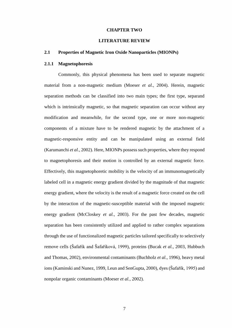
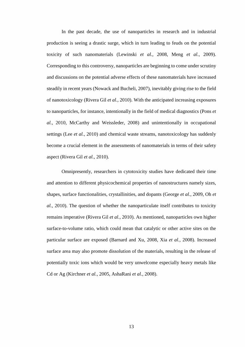
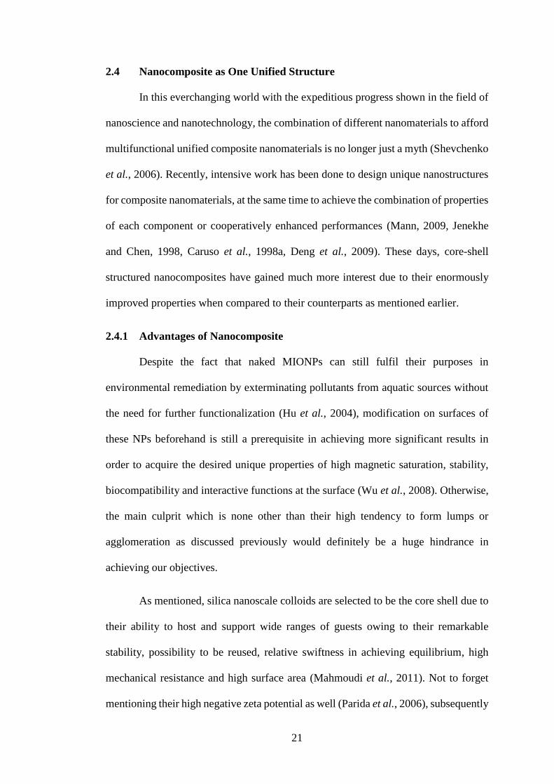
As portrayed in Figure 2.1, the specific surface area increases as particles
become more nanoscaled. Escalating progress made in materials science has enabled
the synthesis and fabrication of various nanostructures with superior physicochemical
properties, primarily because of such exponential increase in surface-to-volume ratio
compared to their bulk counterparts (Rivera Gil et al., 2010, Jang, 2006), particularly
porous NPs (Maurer-Jones et al., 2010).
Figure 2.1: Relationship between specific surface area (m2 kg-1) of a spherical
particle and its size (diameter in nm) with a density of 1000 kg m-3 as an example
(Navarro et al., 2008)
13
In the past decade, the use of nanoparticles in research and in industrial
production is seeing a drastic surge, which in turn leading to feuds on the potential
toxicity of such nanomaterials (Lewinski et al., 2008, Meng et al., 2009).
Corresponding to this controversy, nanoparticles are beginning to come under scrutiny
and discussions on the potential adverse effects of these nanomaterials have increased
steadily in recent years (Nowack and Bucheli, 2007), inevitably giving rise to the field
of nanotoxicology (Rivera Gil et al., 2010). With the anticipated increasing exposures
to nanoparticles, for instance, intentionally in the field of medical diagnostics (Pons et
al., 2010, McCarthy and Weissleder, 2008) and unintentionally in occupational
settings (Lee et al., 2010) and chemical waste streams, nanotoxicology has suddenly
become a crucial element in the assessments of nanomaterials in terms of their safety
aspect (Rivera Gil et al., 2010).
Omnipresently, researchers in cytotoxicity studies have dedicated their time
and attention to different physicochemical properties of nanostructures namely sizes,
shapes, surface functionalities, crystallinities, and dopants (George et al., 2009, Oh et
al., 2010). The question of whether the nanoparticulate itself contributes to toxicity
remains imperative (Rivera Gil et al., 2010). As mentioned, nanoparticles own higher
surface-to-volume ratio, which could mean that catalytic or other active sites on the
particular surface are exposed (Barnard and Xu, 2008, Xia et al., 2008). Increased
surface area may also promote dissolution of the materials, resulting in the release of
potentially toxic ions which would be very unwelcome especially heavy metals like
Cd or Ag (Kirchner et al., 2005, AshaRani et al., 2008).

14
2.2.2.1 Nanotoxicity towards Humans
This extraordinary physicochemical characteristics of nanomaterials might
cause devastating implications to human organs (Lewinski et al., 2008, Nabeshi et al.,
2011, Lee et al., 2011). Due to their nanoscopic nature, these small, subcellular scale
of nanoparticles can expedite their notorious entry to intracellular domains, thereby
invading cellular defenses (Daughton, 2004), causing them to be retained in many cells
and organs to a larger extent as compared to their bulkier forms (Nativo et al., 2008,
Hess and Tseng, 2007). Conceivably, outcomes of the reactive material at the same
concentration can be higher at the intracellular level than at the extracellular level
(Chang et al., 2006) because of the solubilization and degradation occurring inside
cells (Thubagere and Reinhard, 2010). With prolonged exposure to these
nanomaterials, accumulation and retention in the organism, singularly spleen and liver
(Casals et al., 2008) would be unescapable, since the shape of nanoparticles plays a
vital role in a determining response (Albanese et al., 2010, Liu et al., 2009, Hutter et
al., 2010). Furthermore, their geometric effects have been hyped up by the examples
of needle-shaped nanotubes, which have the ability to impale the entire cells (Poland
et al., 2008, Miyawaki et al., 2008). In addition, proteins present in biological media
can readily associate with the nanoparticle surface, specifically protein corona which
alters the features of their interaction with cells (Walczyk et al., 2010, Casals et al.,
2010). Moreover, simply the sorption of endogenous proteins to nanoparticles within
an organism could theoretically elicit an immune response as a result of changing the
native conformation of the exposed protein (Daughton, 2004).
15
2.2.2.2 Nanotoxicity towards Environments
In context here, nanoparticles, in this sense, are examples of indirect toxicants,
where exposure to the parent chemical is not a prerequisite for adverse effects, since
nanoscale by-products from nanotechnology industries would eventually find their
ways and enter aqueous environment (Daughton, 2004). Ecotoxicological studies
show that NPs pose threats to aquatic organisms, both to unicellular organisms (e.g.
bacteria or protozoa) and animals (e.g. Daphnia or fish) (Nowack and Bucheli, 2007).
Potential uptake impacts include direct ingestion or entry across epithelial boundaries
such as gills or body wall (Nowack and Bucheli, 2007). At the cellular level
prokaryotes like bacteria may be largely protected against the uptake of many types of
NPs since they do not have mechanisms for transport of colloidal particles across the
cell wall; unfortunately for eukaryotes, e.g. protists and metazoans, the situation is
different since they have processes for the cellular internalization of nanoscale or
microscale particles, namely endocytosis and phagocytosis (Moore, 2006). Also, there
were reports that latex NPs have been consumed by fish Oryzias latipes, accumulating
those particles not only in their gills and intestine but in brain, testis, liver and blood
as well (Kashiwada, 2006). Meanwhile, plants like algae and fungi could be
detrimentally affected too. Inside their cells, NPs might directly provoke alterations of
membranes and other cell structures and molecules, as well as protective mechanisms
(Navarro et al., 2008). Indirect effects of these NPs depend on their chemical and
physical properties and may include physical restraints (clogging effects),
solubilization of toxic NP compounds, or production of reactive oxygen species
(Navarro et al., 2008).
16
2.3 Polyelectrolytes as Binding Agents
To date, polymers functionalized MIONPs are getting more and more into the
limelight owing to the advantages of polymer coating which increases repulsive forces
to balance the magnetic and van der Waals attractive forces acting on the NPs (Wu et
al., 2008). The formation of these polyelectrolyte adlayers offers electrosteric
repulsions among particles (Runkana et al., 2006) to overcome the attractive
interactions when two particles approach each other at distances less than twice the
adlayer thickness (Lim et al., 2009, Seebergh and Berg, 1994). The synthesis and
fabrication of micro- and nanosized capsules or shells enabling the encapsulation of
diversified structures are of both scientific and technological interest (Langer and
Chasin, 1990). Such particles can be prepared by interfacial polymerization or by
phase separation from a polymer-solvent mixture (Slomkowski and Miksa, 1995), with
these linkers combining the advantages of thin organic films of polyelectrolytes
coupled with the easy handling and applications of colloids (Donath et al., 1998). The
most important novel features of the fabricated polyelectrolyte shells are that firstly,
the composition and thickness of the shells can be controlled; secondly, they can be
fabricated with controlled physical and chemical properties; thirdly, they offer novel
structures for micro- and nanocompartmentalization of materials (Donath et al., 1998).
Additionally, unlike liposome structures (Lasic, 1993), the fabricated shells are readily
permeable by small polar molecules (Caruso et al., 1998b) and are rather stable against
chemical and physical influences (Donath et al., 1998).
It is fascinating to see that various types of species can be embedded and built-
in into one whole unified nanostructure, furnishing specialized and desired customized
properties, making them a huge boon for a wide range of applications (Donath et al.,
1998). One of the most promising alternatives includes the incorporation of catalytic

17
materials like MIONPs inside or onto their inner surface; coupled with the ease of
diffusion of reaction products and substrates, it is undoubtedly a really effective way
to both control and manipulate the efficiency of catalytic processes (Donath et al.,
1998). The control of the chemical composition of the inner surface, or likewise for
outer surface, can be fully utilized to produce nucleation centers for eventual crystal
growth in constrained surroundings, which is a novel way nanocomposites are
produced (Donath et al., 1998).
As for now, a variety of materials for instance, biological macromolecules,
surfactants, phospholipids, nanoparticles, inorganic crystals, and multivalent dyes
have been successfully integrated into polyelectrolyte films by replacing one of the
polyelectrolytes with another species of the same charge to fabricate composite
polyelectrolyte multilayer films (Caruso et al., 1997, Sukhorukov et al., 1996). In this
paper, it is intended that the benefits of these polyelectrolytes can bring about are
wholly employed.

18
2.3.1 Layer by Layer (LBL) Technique
The homogeneities in particle size and loading of magnetic component into
silica particles were not high enough to be applied to highly quantitative analysis
(Matsumoto et al., 2009). Therefore, an approach to obtain monodispersed composite
particles with homogeneous loading of functional component to each particle has been
studied and performed which is the electrostatic heterocoagulation between oppositely
charged particles (Furusawa et al., 1994, Caruso et al., 1999). From here, layer-by-
layer (LBL) technique was born, where it has been used to heterocoagulate MIONPs
onto polystyrene particles (Caruso et al., 1999, Caruso et al., 2001) and silica particles
(Zhu et al., 2003). Among the many methods of preparing thin films, the deposition of
LBL of interdependent polymers has loomed large as a particularly versatile, robust
and flexible technique for gaining control of film thickness and its functionality
(Bruening and Adusumilli). Here, a convenient method to design a bifunctional hybrid
composite integrating the catalytic and magnetic performance together is provided,
because the catalytic sites would not be obstructed and blocked as NPs are effectively
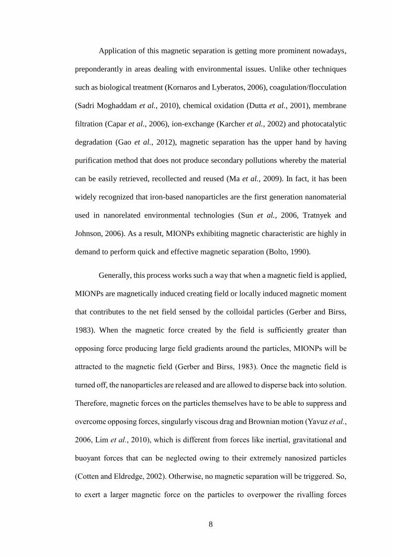
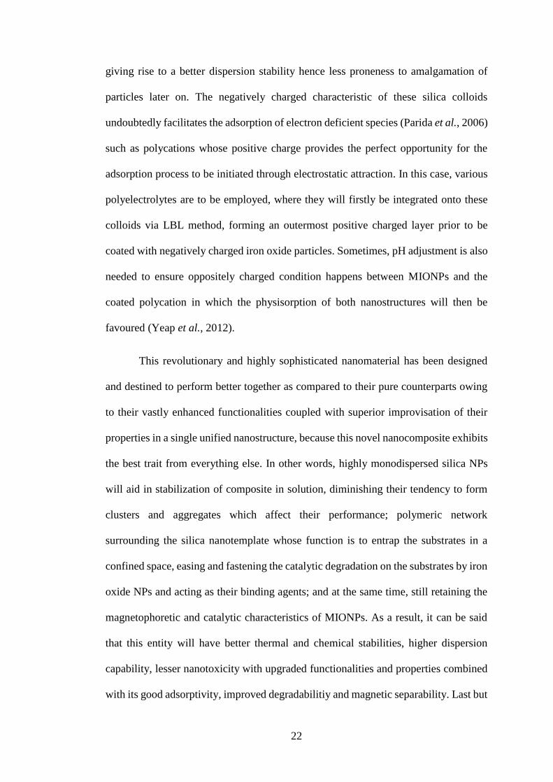
immobilized in the polyelectrolyte layer (Li et al., 2011). Figure 2.2 shows the most
typical form of the LBL method, which is the alternating adsorption of polycations and
polyanions.
Figure 2.2: Schematic illustration of LBL adsorption of polyelectrolyte multilayers
(Decher, 1997)

19
Operationally, this method undergoes through simple, stepwise film formation
by consecutive exposure of the colloids to polyelectrolytes of alternating charge, with
excess unadsorbed polyelectrolyte and supernatants being removed by cycles of
centrifugation and rinsing before the next layer is deposited (Donath et al., 1998,
Bruening and Adusumilli). LBL methods have the advantage that ionic attraction
between opposite charges being the driving force for the multilayer buildup (Decher
et al., 1992), which is in contrast to chemisorption techniques (Merrifield, 1965, Maoz
et al., 1988, Lee et al., 1988) that require a reaction yield of 100% in order to maintain
surface functional density in each layer where no covalent bonds need to be formed
(Decher et al., 1992).
Early studies showed that LBL methods can also use a much broader range of
multiply charged species, including proteins, viruses, NPs, and exfoliated inorganic
materials (Bertrand et al., 2000). Now, in most cases, this method also capitalizes on
other interactions such as hydrogen bonding or covalent linkages (Quinn et al., 2007).
The LBL strategy has the upper hands over most thin film forming methods due to
firstly, this technique offers control over film thickness at nanometer scale because a
single adsorption step can deposit as little as a few angstroms of polymer (Quinn et al.,
2007). Secondly, conformal adsorption happens on substrates with a huge range of
geometries, allowing coating of 3-dimensional objects namely NPs and porous
membranes (Dotzauer et al., 2006, Becker et al., 2010).
The key feature in the deposition of polyelectrolyte multilayers is charge
overcompensation, where the initial layer adsorbs onto the substrate by electrostatic or
hydrophobic interactions and either creates a charged surface or reverses the substrate
surface charge (Schlenoff and Dubas, 2001). Adsorption of subsequent layers again
overcompensates the charge on its surface to reverse the substrate’s charge, permitting
20
adsorption of the next layer (Schlenoff and Dubas, 2001). Most of the time, the
thickness of multilayer polyelectrolyte films increases linearly with the number of
adsorbed layer, suggesting that the extent of charge overcompensation does not differ
dramatically with the number of adsorped layers, so the amount of polyelectrolyte
deposited in each step is approximately constant (Bruening and Adusumilli). It is
suggested that the exponential growth occurs when one of the polyelectrolytes diffuses
“into” the entire film during deposition (Lavalle et al., 2004). Upon addition of the
oppositely charged polyelectrolyte, the previously adsorbed polyelectrolyte diffuses
“out” of the whole film to form a very thick polyanion-polycation complex at the
surface, resulting in an increment of thickness of the multilayer films (Hoda and
Larson, 2009). The LBL approach allows a rich variety of structures to be assembled,
both on planar substrates (Decher, 1997) and on colloidal templates (Caruso, 2000),
allowing a greater degree and extent of structural complexity and numerous
components to be introduced into defined layers, thereby permitting the establishment
of new materials with enormous potentials in broad ranging applications (Caruso et al.,
2001).
21
2.4 Nanocomposite as One Unified Structure
In this everchanging world with the expeditious progress shown in the field of
nanoscience and nanotechnology, the combination of different nanomaterials to afford
multifunctional unified composite nanomaterials is no longer just a myth (Shevchenko
et al., 2006). Recently, intensive work has been done to design unique nanostructures
for composite nanomaterials, at the same time to achieve the combination of properties
of each component or cooperatively enhanced performances (Mann, 2009, Jenekhe
and Chen, 1998, Caruso et al., 1998a, Deng et al., 2009). These days, core-shell
structured nanocomposites have gained much more interest due to their enormously
improved properties when compared to their counterparts as mentioned earlier.
2.4.1 Advantages of Nanocomposite
Despite the fact that naked MIONPs can still fulfil their purposes in
environmental remediation by exterminating pollutants from aquatic sources without
the need for further functionalization (Hu et al., 2004), modification on surfaces of
these NPs beforehand is still a prerequisite in achieving more significant results in
order to acquire the desired unique properties of high magnetic saturation, stability,
biocompatibility and interactive functions at the surface (Wu et al., 2008). Otherwise,
the main culprit which is none other than their high tendency to form lumps or
agglomeration as discussed previously would definitely be a huge hindrance in
achieving our objectives.
As mentioned, silica nanoscale colloids are selected to be the core shell due to
their ability to host and support wide ranges of guests owing to their remarkable
stability, possibility to be reused, relative swiftness in achieving equilibrium, high
mechanical resistance and high surface area (Mahmoudi et al., 2011). Not to forget
mentioning their high negative zeta potential as well (Parida et al., 2006), subsequently
22
giving rise to a better dispersion stability hence less proneness to amalgamation of
particles later on. The negatively charged characteristic of these silica colloids
undoubtedly facilitates the adsorption of electron deficient species (Parida et al., 2006)
such as polycations whose positive charge provides the perfect opportunity for the
adsorption process to be initiated through electrostatic attraction. In this case, various
polyelectrolytes are to be employed, where they will firstly be integrated onto these
colloids via LBL method, forming an outermost positive charged layer prior to be
coated with negatively charged iron oxide particles. Sometimes, pH adjustment is also
needed to ensure oppositely charged condition happens between MIONPs and the
coated polycation in which the physisorption of both nanostructures will then be
favoured (Yeap et al., 2012).
This revolutionary and highly sophisticated nanomaterial has been designed
and destined to perform better together as compared to their pure counterparts owing
to their vastly enhanced functionalities coupled with superior improvisation of their
properties in a single unified nanostructure, because this novel nanocomposite exhibits
the best trait from everything else. In other words, highly monodispersed silica NPs
will aid in stabilization of composite in solution, diminishing their tendency to form
clusters and aggregates which affect their performance; polymeric network
surrounding the silica nanotemplate whose function is to entrap the substrates in a
confined space, easing and fastening the catalytic degradation on the substrates by iron
oxide NPs and acting as their binding agents; and at the same time, still retaining the
magnetophoretic and catalytic characteristics of MIONPs. As a result, it can be said
that this entity will have better thermal and chemical stabilities, higher dispersion
capability, lesser nanotoxicity with upgraded functionalities and properties combined
with its good adsorptivity, improved degradabilitiy and magnetic separability. Last but

23
not least, by having a better grasp and full understanding on controlled structure and
interface interactions between these nanoparticles, nanocomposites can further possess
greater novel physical and chemical characteristics that will be crucial for future
technological applications as well (Wu et al., 2008).
2.4.2 Application of Nanocomposite in Environmental Remediation
The use of different types of dyes in textile, paper, leather, cosmetics and other
industries is well known (Reed et al., 1998). These industries dispose tremendous
amount of dye contents causing devastating turmoil and problems such as increasing
the COD and reducing light penetration and visibility (Murray and Parsons, 2004).
Since dyes are stable, recalcitrant, colorant, and even potentially carcinogenic and
toxic (Wu and Tseng, 2008), their release into the environment results in aesthetical
and detrimental health problems (Saha et al., 2011). Thus, this scenario has become
increasingly worrying and needs to be paid attention to for the potential hazards posed.
Therefore, herein, one of the most prominent properties of magnetic
nanocomposites, that is their advantages of easy isolation via magnetic separation
which is more selective and rapid as compared to both centrifugation and filtration
(Hirschbein et al., 1982, Chang et al., 2005) is fully utilized. This is mainly because
each MIONP exists as a single domain (Faraji et al., 2010) with huge magnetic
moment (Mathew and Juang, 2007), so it could be easily magnetized and removed by
an external applied magnetic field (Vatta et al., 2006). This exceptionally remarkable
magnetic collectability of such nanocomposites is sure to be one of the key
contributors to acting as the emerging paradigm in pollutant removal applications,
albeit factors influencing their collectability such as effect of surface modification
employed have not been completely known and understood yet (Yeap et al., 2012).
24
However, bear in mind that these magnetic nanocomposites deliberately
combined for water remediation purposes have to be separated out eventually so that
pollutant-bound particles would be halted from re-entering into the environment once
again (Yavuz et al., 2006). Upon its certainty in contributing to severe toxicity to
aquatic lives (Nel et al., 2006), it is unacceptable for the magnetic nanocomposites to
be released in a vast amount without proper recovery system. Consequently, effective
clarification technologies (Limbach et al., 2008) are needed and must act as the frontier
area of research before pilot-scale applications of nanocomposites for water
reclamation are intended to be performed (Ambashta and Sillanpää, 2010). Hence,
questions and doubts regarding on how to improve the stability and availability of
functionalized iron oxide NPs in extreme environmental conditions, how to develop
efficient, robust and orderly magnetic nanoassembly structures, and how to realize
large-scale or industrial synthesis need to be urgently solved and overcome for
obtaining an ideal functionalized MIONPs (Wu et al., 2008). In a nutshell, the future
work in this area must be focused on preparing all these functionalized NPs via green
chemistry routes, minimizing environmental pollutions as much as possible.
25
CHAPTER THREE
MATERIALS AND METHODS
3.1 Materials and Equipment
3.1.1 Chemicals and Materials
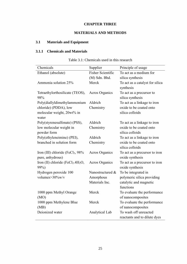
Table 3.1: Chemicals used in this research
Chemicals Supplier Principle of usage
Ethanol (absolute) Fisher Scientific
(M) Sdn. Bhd.
To act as a medium for
silica synthesis
Ammonia solution 25% Merck To act as a catalyst for silica
synthesis
Tetraethylorthosilicate (TEOS),
98%
Acros Organics To act as a precursor to
silica synthesis
Poly(diallyldimethylammonium
chloride) (PDDA), low
molecular weight, 20wt% in
water
Aldrich
Chemistry
To act as a linkage to iron
oxide to be coated onto
silica colloids
Poly(styrenesulfonate) (PSS),
low molecular weight in
powder form
Aldrich
Chemistry
To act as a linkage to iron
oxide to be coated onto
silica colloids
Poly(ethyleneimine) (PEI),
branched in solution form
Aldrich
Chemistry
To act as a linkage to iron
oxide to be coated onto
silica colloids
Iron (III) chloride (FeCl3, 98%
pure, anhydrous)
Acros Organics To act as a precursor to iron
oxide synthesis
Iron (II) chloride (FeCl2.4H2O,
99%)
Acros Organics To act as a precursor to iron
oxide synthesis
Hydrogen peroxide 100
volumes>30%w/v
Nanostructured &
Amorphous
Materials Inc.
To be integrated in
polymeric silica providing
catalytic and magnetic
functions
1000 ppm Methyl Orange
(MO)
Merck To evaluate the performance
of nanocomposites
1000 ppm Methylene Blue
(MB)
Merck To evaluate the performance
of nanocomposites
Deionized water Analytical Lab To wash off unreacted
reactants and to dilute dyes

26
3.1.2 Facilities and Equipment
Table 3.2: Equipment used in this research
Equipment Supplier Principle of usage
Ultrasonic Cleaner Branson Ultrasonics
Corporation
To sonicate for better solution
dispersion
Centrifuge 4000 Kubota Corporation To separate sediments from
supernatants
UV-Vis
Spectrophotometer
Fisher Scientific(M) Sdn.
Bhd.
To observe the dye
absorbance values
Zetasizer Nanoseries
(Malvern)
DKSH Technology Sdn.
Bhd.
To investigation the size
distribution and zeta potential
of synthesized particles
Water bath
(Memmert)
Sterling Ascent Sdn.
Bhd.
To maintain polyelectrolytes
at 40oC
Rotator Stuart To uniformly distribute the
solution
Magnetic stirrer with
magnetic bar
Heidolph To mechanically stir the
solution without heating
Aluminium foil Diamond To act as a protector for
various chemicals
Electronic balance Shimadzu AC 220 To weigh various chemicals
Transmission Electron
Microscope (TEM)
Philips CM12 with Docu
Version 3.2 image
analysis
To determine the morphology
of nanocomposites
27
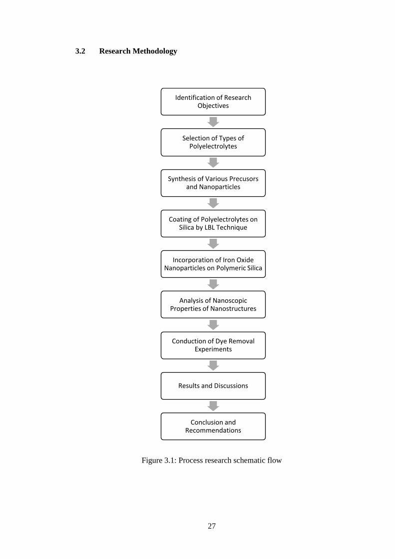
3.2 Research Methodology
Figure 3.1: Process research schematic flow
Identification of Research Objectives
Selection of Types of Polyelectrolytes
Synthesis of Various Precusors and Nanoparticles
Coating of Polyelectrolytes on Silica by LBL Technique
Incorporation of Iron Oxide Nanoparticles on Polymeric Silica
Analysis of Nanoscopic Properties of Nanostructures
Conduction of Dye Removal Experiments
Results and Discussions
Conclusion and Recommendations

28
3.3 Experimental Methods
The pictorial representation of major steps involved in the silica colloid-
polyelectrolyte(s)-MIONPs nanocomposites is illustrated in Figure 3.2.
Figure 3.2: Schematic diagram portraying major steps involved in LBL assembly of
silica-polyelectrolyte(s)-MIONPs nanocomposite (Che et al., 2014)
3.3.1 Preparation of Silica Nanotemplate
Firstly, silica particles were synthesized via Stöber process under room
temperature with the hydrolysis of TEOS in ethanol and further condensation with
ammonia (Stöber et al., 1968). A 60 ml of absolute ethanol was measured and poured
into a 250 ml beaker. A magnetic stirrer bar was dropped into the beaker, where the
latter was put onto a magnetic stirrer with stirring of the mixture at a lower speed. Next,
a 2 ml of tetraethylorthosilicate (TEOS) followed by another 6 ml of ammonia (NH3)
were pipetted dropwise into the mixture in the beaker, and stopwatch was started
immediately. At the same time, the speed of the stirrer was slowly increased to 500
rpm to avoid the mixture from splitting out. Then, parafilm was used to seal the beaker
to prevent ethanol from evaporating out. After the mixture was left to stir for 2 hours,
the initially colourless solution would turn cloudy indicating that silica had been
formed and suspended in solution. The stirrer was turned off and a magnetic bar was

29
used to separate the solution out of the beaker. A total of 68 ml of solution was then
poured into two separate 50 ml centrifugal tubes, where centrifugation of 7000x g for
25 minutes was done. Subsequently, the supernatants from the tubes were poured out
and washed with deionized (DI) water immediately. The precipitates were redispersed
in DI using a sonicator, and DI washing step was repeated for another three times.
Finally, the solutions from both tubes were combined into one, where the silica was
synthesized, ready for size distribution and zeta potential measurements.
3.3.2 Size Distribution and Zeta Potential Measurements
For any samples, the procedures were all the same. For size distribution
measurement, firstly, a 3 ml of DI water was prepared in a cuvette. Then, a 20 μL of
sample was pipetted into the cuvette, before being sonicated in ultrasonic cleaner for
few minutes. Subsequently, the whole solution was transferred to another smooth
cuvette before being measured by Zetasizer Nanoseries. Meanwhile for zeta potential
measurement, a 1 ml of 1 mM NaCl was prepared in a cuvette as well, where another
20 μL of sample was dropped into it and sonicated. Lastly, a 750 μL of the mixture was
pipetted into a folded capillary cell meant only for zeta potential measurement.
3.3.3 Preparation of PDDA Solution
For ease of calculation, a 0.01 g/ml concentration was standardized for all the
solutions involved. A concentration of 0.01 g/ml of PDDA solution was used to coat
the silica nanoparticles. Firstly, a 45 ml of DI water was measured and poured into a
50 ml centrifugal tube. Next, a 433 μL of pure PDDA was added into the tube, with a
subsequent of 1 hour sonication in an ultrasonic cleaner for its dispersion. Then, the
dispersed PDDA solution was left in water bath at 40oC for a day, ready for size
distribution and zeta potential measurements.
30
3.3.4 Preparation of PSS Solution
A 0.01 g/ml concentration of PSS solution was prepared by having 0.45 g of
PSS powder mixed with 45 ml of DI water in a centrifugal tube. Again, the solution
was left for sonication for an hour in an ultrasonic cleaner and left in water bath at
40oC for a day, ready for size distribution and zeta potential measurements.
3.3.5 Preparation of PEI Solution
A 0.01 g/ml concentration of PEI solution was prepared by having 0.45 g of
PEI solution (due to its extremely high viscosity) mixed with 45 ml of DI water in a
centrifugal tube. The solution was also left for sonication for an hour in an ultrasonic
cleaner and left in water bath at 40oC for a day, ready for size distribution and zeta
potential measurements.
3.3.6 Preparation of Iron Oxide Nanoparticles Solution
Here, iron oxide nanoparticles were synthesized through Co-Precipitation
Method, with its theoretical background of:
𝐹𝑒2+ + 2𝐹𝑒3+ + 8𝑂𝐻− → 𝐹𝑒3𝑂4 + 4𝐻2𝑂
Best ratio Fe3+ / Fe2+ = 2/1
Firstly, a 60 ml of DI water was prepared inside a 3-neck round bottom flask
placed on a magnetic stirrer and was bubbled with Argon gas for a period of 20 minutes.
The flow rate of the gas was set to 400 ml/min with a pressure of 1 bar. Then, the
openings of the flask were covered with a cork and few layers of parafilms respectively,
with 2 syringe holes poked on top of the parafilm layer of the centre neck. Next, iron
(III) chloride (FeCl3) and iron (II) chloride (FeCl2.4H2O) as precursors were prepared
at a mole ratio of 2:1, which is (0.3244:0.1988) g. The prepared salts were added and
dissolved into the treated DI water. Subsequently, a rapid stirring at 700 rpm with a
31
magnetic stirrer bar with the continued bubbling of argon gas was done, and the
mixture was left to stir for another 20 minutes. Once done, argon gas was removed and
openings of flask (centre and argon gas) were covered with few parafilm layers. Then,
the mixture was heated using a temperature controller with thermocouple. Once the
temperature was left to reach 70oC, a 5 ml of 2.5 M NaOH solution was injected into
the mixture using a syringe, causing a change in colour for the mixture from light
brown to black. The reaction was allowed to continue for another 30 minutes before
the black precipitate was collected by permanent magnet. The iron oxide nanoparticles
synthesized were washed with DI water to remove the supernatants, and was
centrifuged at 10000x g for 10 minutes. Lastly, the precipitate was redispersed in DI
water. The iron oxide nanoparticles solution was synthesized, ready for concentration
measurement.
3.3.7 Preparation of Polymeric-Coated Silica Nanoparticles
A precursor film was formed by the alternate adsorptions of PDDA, PSS and
PDDA polymers from aqueous solutions onto the silica microspheres by sequential
layering approach. All the steps employed to coat these polymers on silica core shell
were performed in an ultrasonic cleaner to facilitate a better and more uniform particle
dispersion and coating. For the first PDDA layer coating, after some calculations, a
0.506 ml of 0.01 g/ml silica colloid solution was needed to be added into the 45 ml of
0.01 g/ml PDDA solution, Firstly, both of the solutions prepared earlier were sonicated
in ultrasonic cleaner for 15 minutes, before the 0.506 ml silica was pipetted out and
dropped slowly into the centrifugal tube of 45 ml PDDA solution. Next, the whole
0.01 g/ml solution was sonicated in ultrasonic cleaner for 1 hour, prior to being left at
a rotator with 37 rpm for a day. After one day, the solution was centrifuged at 3500x
g for 10 minutes, and supernatants were separated out followed by DI water washing
32
as done previously. The centrifugation was repeated once more, before DI water was
flushed in until a 2 ml of solution was obtained. The PDDA coated silica solution was
synthesized, ready for size distribution and zeta potential measurements. For PSS
coating, the 2 ml of 0.01 g/ml silica-PDDA solution prepared earlier was also sonicated
15 minutes hour beforehand together with the prepared 45 ml of 0.01 g/ml PSS
solution. Then, the whole 2 ml of silica-PDDA solution was pipetted dropwise into the
centrifugal tube of the 45 ml PSS solution. Steps of sonication, rotation, centrifugation
and washing with DI water were repeated again. Lastly, a 2 ml of silica-PDDA-PSS
solution was synthesized, ready for size distribution and zeta potential measurements.
For the subsequent PDDA layer coating, again, the steps above were repeated by just
replacing the 2 ml of 0.01 g/ml silica-PDDA solution with the 2 ml of 0.01 g/ml silica-
PDDA-PSS synthesized earlier. Finally, a 2 ml of silica-PDDA-PSS-PDDA solution
was synthesized, ready for size distribution and zeta potential measurements. The
amount of iron oxide needed to be pipetted out from the stock was then calculated.
For PEI and a single PDDA coating during the 2nd and 3rd experiments, the
whole procedure was repeated by replacing the first layer of PDDA coating earlier
with just a layer of PEI and a layer of PDDA respectively. Lastly, a silica-PEI and
silica-PDDA solutions were synthesized, ready for size distribution and zeta potential
measurements. The amount of iron oxide needed was then calculated as well.
3.3.8 Preparation of Silica-Polyelectrolyte(s)-MIONPs Nanocomposite
Firstly, the iron oxide stock prepared earlier was sonicated along with the
silica-PDDA-PSS-PDDA for an hour. Then, a 3.96 ml of iron oxide from stock
calculated earlier was added into a 50 ml of DI water dropwise in a centrifuged tube,
done in ultrasonic cleaner to have uniform coating. After sonication of an hour, the
iron oxide NPs were ready for size distribution and zeta potential measurements. Once
33
done, coating of 1 ml silica-PDDA-PSS-PDDA was continued by having it dropped
into the centrifuged tube and left at the rotator for one day. After one day, the solution
was centrifuged at 10000x g for 10 minutes, and supernatants were separated out aided
by an external magnet. Lastly, the unified silica-PDDA-PSS-PDDA-iron oxide
nanocomposite was obtained, ready for size distribution and zeta potential
measurements. The whole step was repeated using silica-PEI and silica-PDDA
structures as well.
3.3.9 Preparation of Methylene Blue (MB) Dye
A 20 ppm of MB solution was prepared from 10000 ppm of MB solution to
make up a total of 10 mL solution with 1 mL 0.01g/mL silica suspension solution.
Therefore, 8.98 mL of DI was transferred into 200 mL beaker followed by the addition
of 0.02 mL of 10000 ppm MB solution. The 200 mL beaker containing the total volume
of 9 mL MB solution was covered with parafilm before dispersing it in an ultrasonic
cleaner for 1 hour. After sonicating the solution for an hour, the solution was stored in
dark conditions ready to be used.
3.3.10 Preparation of Methyl Orange (MO) Dye
A 20 ppm of MO solution was prepared from 2000 ppm of MO solution to
make up a total of 10 mL solution with 1 mL 0.01g/mL silica suspension solution.
Therefore, 8.98 mL of DI was transferred into 200 mL beaker followed by the addition
of 0.1 mL of 2000 ppm MO solution. The 200 mL beaker containing the total volume
of 9 mL MO solution was covered with parafilm before dispersing it in an ultrasonic
cleaner for 1 hour. After sonicating the solution for an hour, the solution was stored in
dark conditions ready to be used.

34
3.3.11 Dye Removal
1 ml of each sample namely silica, various polymeric silica and iron oxide-
polymeric silica nanocomposite solutions was placed in a vial. Then, a 9 ml of 20 ppm
MB was added into the solution, left at rotator for 15 minutes (reaction time). For
nanocomposites, an additional step in which an external magnet was first used to
collect the magnetic nanocomposite in the mixture obtaining the initial supernatant
before its 1 ml from the total 10 ml mixture solution was taken and poured into a
centrifugal tube, centrifuged at a speed of 10000 rpm for 30 minutes to obtain the
remaining supernatant for the absorbance analysis in order to observe the dye remained.
Different reaction times up to 360 minutes were employed and repeated. Subsequently,
the procedure for the MO dye removal was performed with the same steps above.
The whole procedure was repeated again only with the difference of an 8.5 ml
of 20 ppm MB and MO instead of the 9.0 ml previously, with an addition of 0.5 ml of
H2O2 into the vial.
35
CHAPTER FOUR
RESULTS AND DISCUSSION
Silica NPs were chosen to serve as nanotemplates for the synthesis of
nanocomposite fabrications in this study using three different types of polyelectrolytes:
(1) a single layer of PDDA, (2) a three multilayer of PDDA, PSS and PDDA and, (3)
a single layer of PEI. In the first experiment, since silica NP is negatively charged, the
introduction of a single layer of PDDA polycation would modify the silica NPs to
become positively charged before negatively charged iron oxide NPs could be
incorporated into silica NPs, exhibiting catalytic and magnetic bifunctionalities in one
unified nanostructure for environmental remediation. Another two experiments were
repeated with: the alternating coating of polycations and polyanion which are the
PDDA, PSS and PDDA multilayers through the LBL method instead of just a single
layer of PDDA; and a single layer of PEI as the polyelectrolyte respectively. In the
second experiment, the establishment of the first layer of PDDA would also modify
the silica NPs to become positively charged before being realtered by PSS polyanion
to become negatively charged, only to be remodified again by another layer of PDDA
to become positively charged once more, before negatively charged iron oxide NPs
were again incorporated into the silica core. In the third experiment, PEI was used
instead of the PDDA layer from the first experiment. Both PDDA and PSS are linear
polyelectrolytes while PEI is of branched configuration. These synthesized
nanomaterials were observed and analyzed under Dynamic Light Scattering (DLS) and
Transmission Electron Microscope (TEM) equipment. From these experiments, it
could be said that these nanocomposites showed good dye removal efficiencies.
36
4.1 Characterization and Observation
This LBL technique was used to necessitate the consecutive adsorption of
oppositely charged nanocomponents onto colloidal core particles where
polyelectrolytes play their roles as binding agents by acting as intermediate layers for
integration of iron oxide NPs, retaining both their magnetophoretic and catalytic
characteristics. Formation of the ultimate structure of PDDA, PDDA-PSS-PDDA and
PEI polyelectrolye-modified nanosized silica core were visualized using TEM.
4.1.1 Synthesis of Silica Nanoparticles
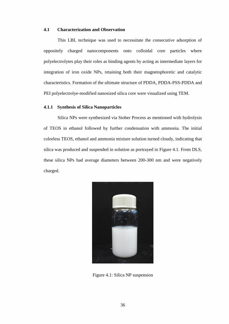
Silica NPs were synthesized via Stober Process as mentioned with hydrolysis
of TEOS in ethanol followed by further condensation with ammonia. The initial
colorless TEOS, ethanol and ammonia mixture solution turned cloudy, indicating that
silica was produced and suspended in solution as portrayed in Figure 4.1. From DLS,
these silica NPs had average diameters between 200-300 nm and were negatively
charged.
Figure 4.1: Silica NP suspension

37
4.1.2 Synthesis of Polymeric-Coated Silica Nanoparticles
Colorless pure PDDA reagent, PEI highly-viscous liquid and PSS powder were
all mixed with DI water to prepare their respective solutions. These polymeric-
modified silica NPs synthesized were analyzed under DLS in determining their sizes
and zeta potentials before proceeding to latter stages. The ever-occurring reversals of
zeta potential values observed at each stage of new coated nanoparticles synthesis
compared to their previous NPs suggested that the subsequent desired layers were
successfully coated on the core and prior NP surfaces (Che et al., 2014). The PDDA-
PSS-PDDA and PEI modified silica NP suspensions were shown in Figure 4.2 (a) and
(b) respectively, also in milky colors but with less intensities after dilution with DI
water.
Figure 4.2: (a) PDDA-PSS-PDDA-modified silica NP suspension, and (b) PEI-
modified silica NP suspension
a b

38
4.1.3 Synthesis of Iron Oxide Nanoparticles
Iron oxide NPs were synthesized through Co-Precipitation Method described
previously. The black precipitate was collected by an external magnet as shown in
Figure 4.3, so that the MIONPs synthesized could be washed with DI water to remove
supernatants. Zeta potential of negative value was made sure to be obtained under DLS,
so that MIONPs could be amalgamated onto oppositely charged polymeric matrix
surfaces synthesized earlier. Since at low pH, iron oxides are positively charged and
attract negatively charged ligands; hence, when solution pH (DI water) was above the
isoelectric point (pH = ~8), the oxide surface became negatively charged and could
form surface complexes with cations (Sun et al., 2006) such as PDDA and PEI
polycations as our outermost layers in all three experiments here. Therefore, DI water
was ensured to always be in between pH of 8 to 10 in order to have the oxide surface
negatively charged. Meanwhile, Figure 4.4 depicted TEM micrograph of MIONPs,
where their clustering was due to magnetic interactions (Phenrat et al., 2007).
Figure 4.3: Collection of iron oxide NP suspension with a magnetic bar

39
Figure 4.4: TEM micrograph of iron oxide NP aggregration
4.1.4 Synthesis of Silica-Polyelectrolyte(s)-MIONPs Nanocomposite
These polymeric-modified silica NPs were dropped into iron oxide NP solution
to be coated in order to synthesize the desired nanocomposites. In the meantime, the
heterocoagulation between MIONPs on the surface of a PDDA-modified silica core, a
PDDA-PSS-PDDA-modified silica core and a PEI-modified silica core could be
visualized through TEM micrographs in Figure 4.5 (a), (b) and (c) respectively.
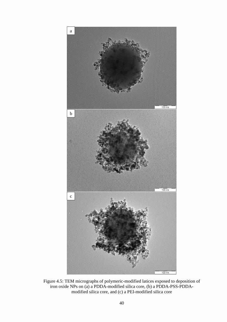
40
Figure 4.5: TEM micrographs of polymeric-modified latices exposed to deposition of
iron oxide NPs on (a) a PDDA-modified silica core, (b) a PDDA-PSS-PDDA-
modified silica core, and (c) a PEI-modified silica core
a
b
c

41
It was seen that all three TEM images differed from each other through their
structural morphologies. As mentioned in problem statement, these architectures were
proposed with the intention to understand more on their behaviors in terms of their
confinement of iron oxide NPs through dye removal performance which will be
discussed later. From their structural morphologies, it was illustrated that the one in
Figure 4.5 (a) has the thinnest outermost iron oxide NPs layered structure as compared
to that in (b) and (c), where both the latters have thicker layers covered on their silica
cores. This was due to the simple fact that only a single linear layer of polyelectrolyte
was formed in (a) but three layers of alternatingly charged polyelectrolytes were
fabricated in (b). As in uniformities, (c) showed more irregularities to (a) and (b),
which was attributable to the difference in their polymeric configurations. The single
layer PDDA and multilayer PDDA-PSS-PDDA polyelectrolytes in (a) and (b) are all
linear, while the single layer of PEI polyelectrolyte (c) is a branched type, where it was
believed to have caused the latter to possess a higher total surface area to volume ratio.
42
4.1.5 Zeta Potential and Particle Size
The zeta potential and particle size of various synthesized NPs were analyzed
using Malvern Zetasizer Nanoseries and were summarized in Table 4.1 to 4.3.
For the first experiment seen in Table 4.1, from DLS, the uncoated silica NP
yielded a zeta potential of -58.4 mV in 1 mM NaCl. The presence of PDDA
polyelectrolyte caused a reversal in its zeta potential to +52.4 mV, a value consistent
with the outer layer being a polycation. The zeta potential value turned positive when
this layer of PDDA formed the outer layer and in between -26.0 mV of iron oxide NPs
as the outermost layer, acting as a bridging agent to facilitate the assimilation of iron
oxide NPs by electrostatic attraction to synthesize the magnetic nanocomposite. At the
end of the day, the ultimate nanocomposite exhibited an overall zeta potential of +23.7
mV instead of the localized negative value of zeta potential from iron oxide NPs. This
result indicated that the iron oxide NPs incorporated into the polymeric matrix have
successfully suppressed the more highly positively charged PDDA, leading to a net
lower value of positively charged nanocomposite.
The colloidal stability of the coated nanocomposite was higher when PDDA,
rather than iron oxide, formed the outlayer as slow flocculation of the multilayer-
coated nanocomposite happened when the latter was the outermost layer (Zhu et al.,
2003). This was due to electrosteric stabilization of the NPs conferred by the
polyelectrolyte (Caruso et al., 1999, Lvov et al., 1997, Caruso and Möhwald, 1999).
However, the nanocomposite was easily redispersable by gentle shaking.
As for the hydrodynamic diameters, from DLS, coating silica NP with PDDA
layer increased its diameter from 209.4 nm to 234.4 nm. Meanwhile, iron oxide NPs
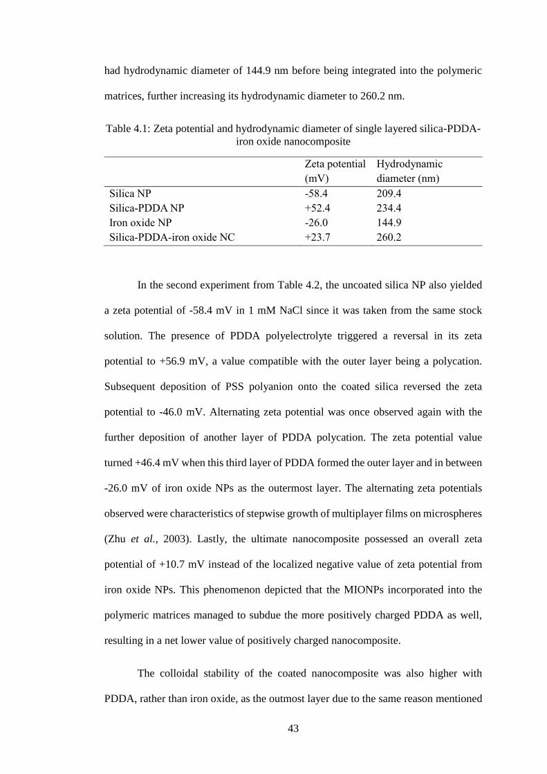
43
had hydrodynamic diameter of 144.9 nm before being integrated into the polymeric
matrices, further increasing its hydrodynamic diameter to 260.2 nm.
Table 4.1: Zeta potential and hydrodynamic diameter of single layered silica-PDDA-
iron oxide nanocomposite
Zeta potential
(mV)
Hydrodynamic
diameter (nm)
Silica NP -58.4 209.4
Silica-PDDA NP +52.4 234.4
Iron oxide NP -26.0 144.9
Silica-PDDA-iron oxide NC +23.7 260.2
In the second experiment from Table 4.2, the uncoated silica NP also yielded
a zeta potential of -58.4 mV in 1 mM NaCl since it was taken from the same stock
solution. The presence of PDDA polyelectrolyte triggered a reversal in its zeta
potential to +56.9 mV, a value compatible with the outer layer being a polycation.
Subsequent deposition of PSS polyanion onto the coated silica reversed the zeta
potential to -46.0 mV. Alternating zeta potential was once observed again with the
further deposition of another layer of PDDA polycation. The zeta potential value
turned +46.4 mV when this third layer of PDDA formed the outer layer and in between
-26.0 mV of iron oxide NPs as the outermost layer. The alternating zeta potentials
observed were characteristics of stepwise growth of multiplayer films on microspheres
(Zhu et al., 2003). Lastly, the ultimate nanocomposite possessed an overall zeta
potential of +10.7 mV instead of the localized negative value of zeta potential from
iron oxide NPs. This phenomenon depicted that the MIONPs incorporated into the
polymeric matrices managed to subdue the more positively charged PDDA as well,
resulting in a net lower value of positively charged nanocomposite.
The colloidal stability of the coated nanocomposite was also higher with
PDDA, rather than iron oxide, as the outmost layer due to the same reason mentioned
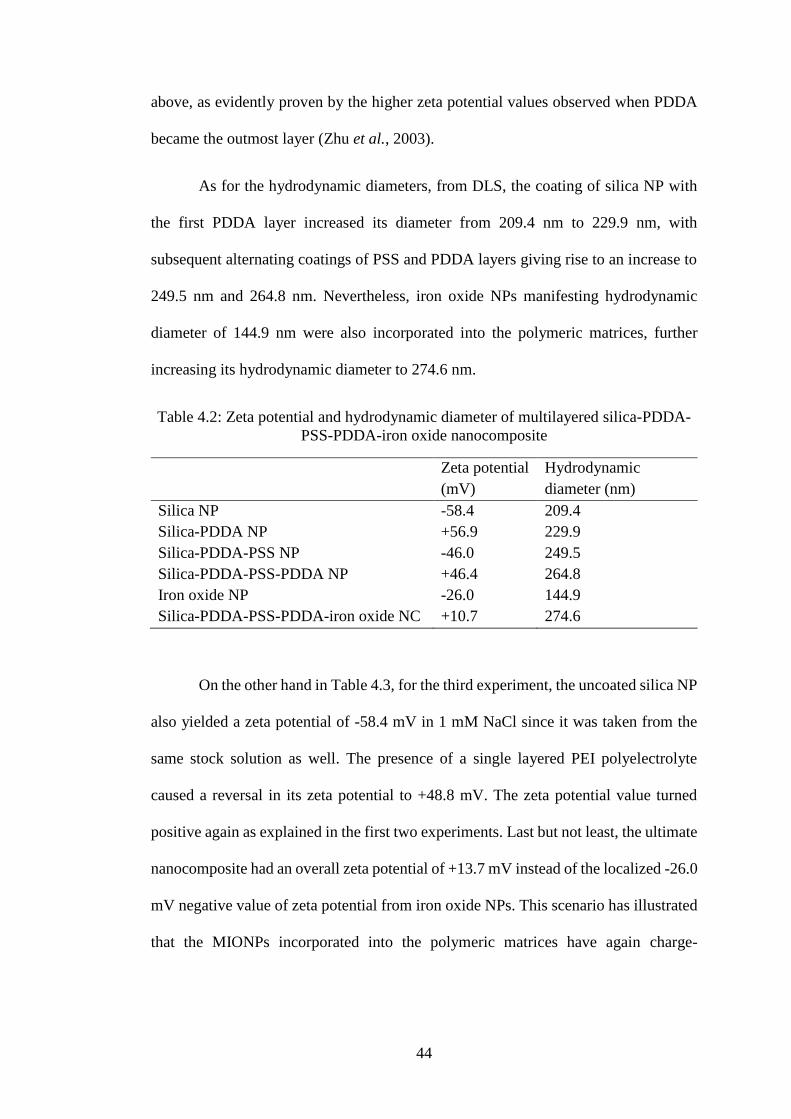
44
above, as evidently proven by the higher zeta potential values observed when PDDA
became the outmost layer (Zhu et al., 2003).
As for the hydrodynamic diameters, from DLS, the coating of silica NP with
the first PDDA layer increased its diameter from 209.4 nm to 229.9 nm, with
subsequent alternating coatings of PSS and PDDA layers giving rise to an increase to
249.5 nm and 264.8 nm. Nevertheless, iron oxide NPs manifesting hydrodynamic
diameter of 144.9 nm were also incorporated into the polymeric matrices, further
increasing its hydrodynamic diameter to 274.6 nm.
Table 4.2: Zeta potential and hydrodynamic diameter of multilayered silica-PDDA-
PSS-PDDA-iron oxide nanocomposite
Zeta potential
(mV)
Hydrodynamic
diameter (nm)
Silica NP -58.4 209.4
Silica-PDDA NP +56.9 229.9
Silica-PDDA-PSS NP -46.0 249.5
Silica-PDDA-PSS-PDDA NP +46.4 264.8
Iron oxide NP -26.0 144.9
Silica-PDDA-PSS-PDDA-iron oxide NC +10.7 274.6
On the other hand in Table 4.3, for the third experiment, the uncoated silica NP
also yielded a zeta potential of -58.4 mV in 1 mM NaCl since it was taken from the
same stock solution as well. The presence of a single layered PEI polyelectrolyte
caused a reversal in its zeta potential to +48.8 mV. The zeta potential value turned
positive again as explained in the first two experiments. Last but not least, the ultimate
nanocomposite had an overall zeta potential of +13.7 mV instead of the localized -26.0
mV negative value of zeta potential from iron oxide NPs. This scenario has illustrated
that the MIONPs incorporated into the polymeric matrices have again charge-

45
neutralized the more positively charged PEI as well, resulting to a net lower value of
positively charged nanocomposite.
The colloidal stability of the coated nanocomposite was also higher with PEI,
rather than iron oxide, as the outmost layer as shown by the higher zeta potential values
observed when PEI being the outermost layer (Zhu et al., 2003).
As for the hydrodynamic diameters, the deposition of silica NP with PEI
increased its diameter from 209.4 nm to 264.8 nm. Meanwhile, iron oxide NPs
exhibiting hydrodynamic diameter of 144.9 nm were amalgamated into the polymeric
matrices, further increasing its hydrodynamic diameter to 318.2 nm.
Table 4.3: Zeta potential and hydrodynamic diameter of single-layered silica-PEI-
iron oxide nanocomposite
Zeta potential
(mV)
Hydrodynamic
diameter (nm)
Silica NP -58.4 209.4
Silica-PEI NP +48.8 264.8
Iron oxide NP -26.0 144.9
Silica-PEI-iron oxide NC +13.7 318.2

46
4.2 Performance Evaluation
The absorbance values of dyes were analyzed using UV-Vis
Spectrophotometer with maximum absorbance wavelength for MB at 665 nm and MO
at 465 nm. The concentration of dyes in the reaction mixture was determined by
measuring the absorption intensity at respective wavelengths and with calibration
curves at different reaction times, from 15 minutes up to 6 hours. Inevitably, the
absorbance values decreased after the degradation and removal processes since the
remaining concentration of dye was reduced. Prior to that, calibration curves were
acquired using the standard MB and MO solutions with known concentrations. The
dye decolorization efficiency is defined as:
𝐷𝑒𝑐𝑜𝑙𝑜𝑟𝑖𝑧𝑎𝑡𝑖𝑜𝑛 𝑒𝑓𝑓𝑖𝑐𝑖𝑒𝑛𝑐𝑦 (%) = (1 −𝐶𝑡
𝐶0) × 100%
where C0 is the initial concentration of dyes and Ct is the concentration of dyes at
certain reaction time, t (min).
4.2.1 Removal of 20 ppm Methylene Blue Dye
Figure 4.6 (a) portrayed the structural formula of positively charged MB, and
(b) showed two vials after the removal process in one of the timelines, where the vial
on the left was before and on the right was after the reaction time. Meanwhile from
Figure 4.7 to 4.9, various time intervals (from 15 minutes to 6 hours) of dye removal
using MB were employed to compare the removal efficiency by different decolorizing
agents from various nanocomposites.

47
Figure 4.6: (a) MB structural formula and (b) MB solution before and after reaction
In the first experiment involving single layered PDDA nanocomposite shown
in Figure 4.7, silica achieved 94.6 %, silica-PDDA with 20.3 %, silica-PDDA-iron
oxide with 61.0 % (absorption only) and silica-PDDA-iron oxide (absorption with
Fenton reaction) achieved 90.1 % of removal efficiencies in MB removal tests.
Silica NP was able to decolorize MB with the highest percentage among all
due to the electrostatic driven process conferred. Positively charged MB was most
favored to highly negatively charged silica and thus, was attracted and adsorbed by
silica the most resulting in the highest removal efficiency. However, the surface charge
of silica core was reversed to positive charge once silica NPs were coated with a layer
of PDDA polycation. Therefore, due to electrostatic repulsion between both positively
charged MB and silica-PDDA, adsorption of MB by silica-PDDA was unfavorable,
giving rise to the lowest removal efficiency. MB could be removed better by lower
degree of positively charged silica-PDDA-iron oxide nanocomposite as compared with
a b

48
higher degree of positively charged silica-PDDA NP for there was still electrostatic
attraction between positively charged MB to the localized outmost layer of negatively
charged iron oxide NPs, albeit slightly. Further degradation process of MB via Fenton
reaction attributed by iron oxide NPs and H2O2 reagent enhanced the removal
efficiency of this silica-PDDA-iron oxide nanocomposite.
Figure 4.7: Percentage removals for 20 ppm MB tests using silica-PDDA-iron oxide
nanocomposite
In the third experiment involving PEI single layered nanocomposite shown in
Figure 4.8, silica from the same stock achieved 94.6 % as well, silica-PEI with 22.1 %,
silica-PEI-iron oxide with 63.1 % (absorption only) and silica-PEI-iron oxide
(absorption with Fenton reaction) achieved 92.6 % of removal efficiencies in MB
removal tests.
0
10
20
30
40
50
60
70
80
90
100
0 50 100 150 200 250 300 350 400
Per
cen
tage
rem
ova
l, %
Time, min
Silica Silica-PDDA Silica-PDDA-IO Silica-PDDA-IO (with Fenton)
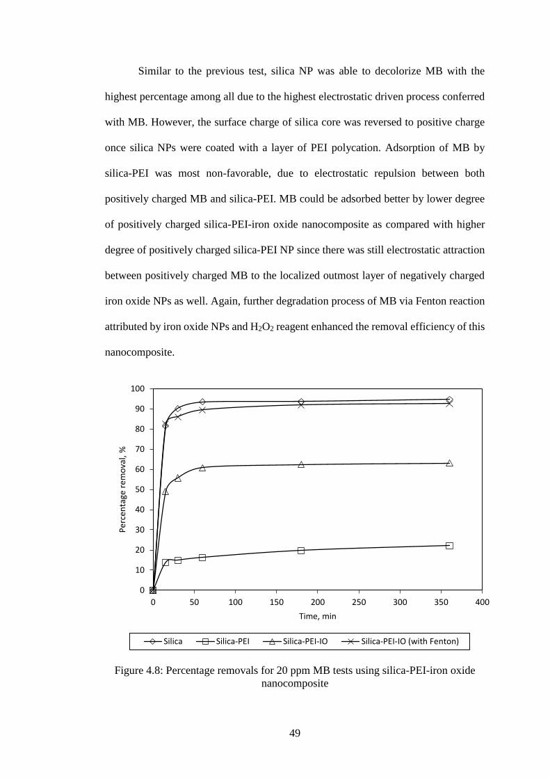
49
Similar to the previous test, silica NP was able to decolorize MB with the
highest percentage among all due to the highest electrostatic driven process conferred
with MB. However, the surface charge of silica core was reversed to positive charge
once silica NPs were coated with a layer of PEI polycation. Adsorption of MB by
silica-PEI was most non-favorable, due to electrostatic repulsion between both
positively charged MB and silica-PEI. MB could be adsorbed better by lower degree
of positively charged silica-PEI-iron oxide nanocomposite as compared with higher
degree of positively charged silica-PEI NP since there was still electrostatic attraction
between positively charged MB to the localized outmost layer of negatively charged
iron oxide NPs as well. Again, further degradation process of MB via Fenton reaction
attributed by iron oxide NPs and H2O2 reagent enhanced the removal efficiency of this
nanocomposite.
Figure 4.8: Percentage removals for 20 ppm MB tests using silica-PEI-iron oxide
nanocomposite
0
10
20
30
40
50
60
70
80
90
100
0 50 100 150 200 250 300 350 400
Per
cen
tage
rem
ova
l, %
Time, min
Silica Silica-PEI Silica-PEI-IO Silica-PEI-IO (with Fenton)
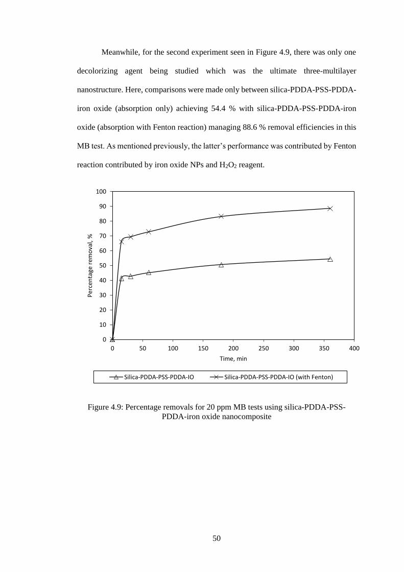
50
Meanwhile, for the second experiment seen in Figure 4.9, there was only one
decolorizing agent being studied which was the ultimate three-multilayer
nanostructure. Here, comparisons were made only between silica-PDDA-PSS-PDDA-
iron oxide (absorption only) achieving 54.4 % with silica-PDDA-PSS-PDDA-iron
oxide (absorption with Fenton reaction) managing 88.6 % removal efficiencies in this
MB test. As mentioned previously, the latter’s performance was contributed by Fenton
reaction contributed by iron oxide NPs and H2O2 reagent.
Figure 4.9: Percentage removals for 20 ppm MB tests using silica-PDDA-PSS-
PDDA-iron oxide nanocomposite
0
10
20
30
40
50
60
70
80
90
100
0 50 100 150 200 250 300 350 400
Per
cen
tage
rem
ova
l, %
Time, min
Silica-PDDA-PSS-PDDA-IO Silica-PDDA-PSS-PDDA-IO (with Fenton)

51
4.2.2 Removal of 20 ppm Methyl Orange Dye
Figure 4.10 (a) illustrated the structural formula of negatively charged MO, and
(b) depicted two vials after removal process in one of the timelines, where the vial on
the left was before and on the right was after the reaction time. From Figure 4.11 to
4.13, various time intervals of dye removal (from 15 minutes to 6 hours) using MO
were employed to compare the removal efficiency by various decolorizing agents from
different nanocomposites.
Figure 4.10: (a) MO structural formula and (b) MO solution before and after reaction
In the first experiment involving single layered PDDA nanocomposite shown
in Figure 4.11, silica achieved 3.4 %, silica-PDDA with 52.6 %, silica-PDDA-iron
oxide with 50.9 % (absorption only) and silica-PDDA-iron oxide (absorption with
Fenton reaction) achieved 57.8 % of removal efficiencies in MO removal tests.
Unlike in MB test, silica NP had the lowest percentage efficiency here due to
electrostatic repulsion of both negatively charged silica and MO, causing limitations
a b
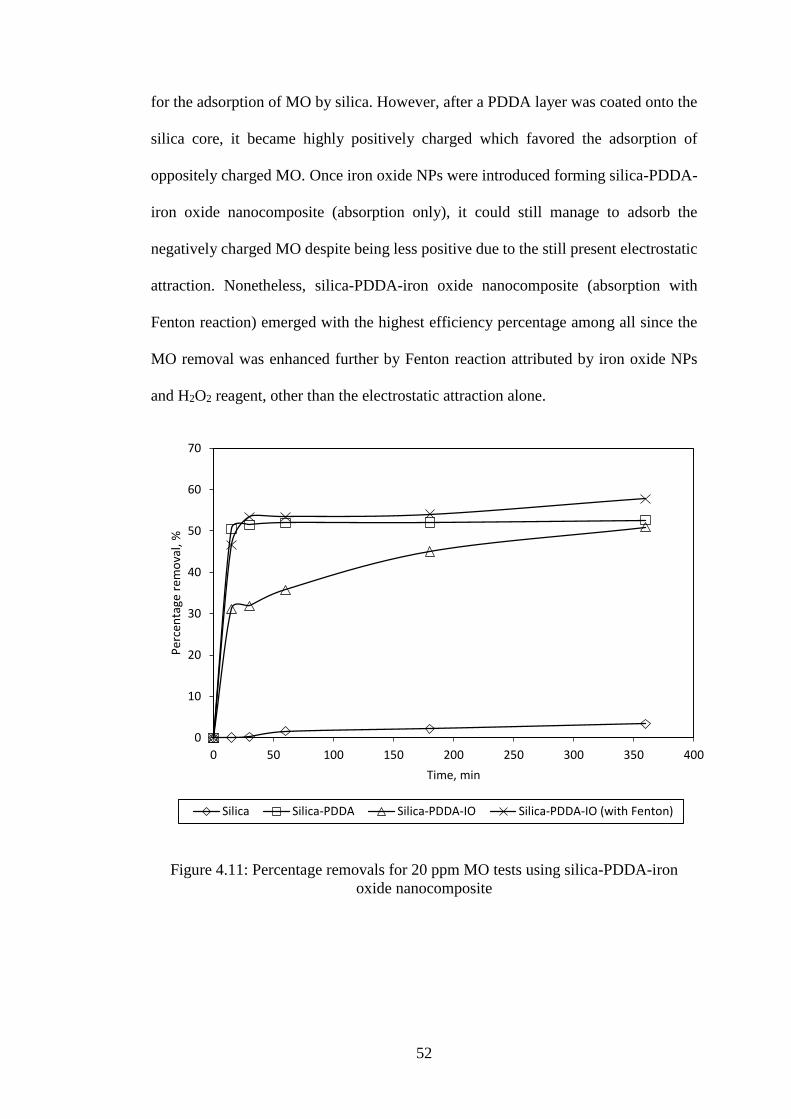
52
for the adsorption of MO by silica. However, after a PDDA layer was coated onto the
silica core, it became highly positively charged which favored the adsorption of
oppositely charged MO. Once iron oxide NPs were introduced forming silica-PDDA-
iron oxide nanocomposite (absorption only), it could still manage to adsorb the
negatively charged MO despite being less positive due to the still present electrostatic
attraction. Nonetheless, silica-PDDA-iron oxide nanocomposite (absorption with
Fenton reaction) emerged with the highest efficiency percentage among all since the
MO removal was enhanced further by Fenton reaction attributed by iron oxide NPs
and H2O2 reagent, other than the electrostatic attraction alone.
Figure 4.11: Percentage removals for 20 ppm MO tests using silica-PDDA-iron
oxide nanocomposite
0
10
20
30
40
50
60
70
0 50 100 150 200 250 300 350 400
Per
cen
tage
rem
ova
l, %
Time, min
Silica Silica-PDDA Silica-PDDA-IO Silica-PDDA-IO (with Fenton)

53
In the third experiment involving PEI single layered nanocomposite shown in
Figure 4.12, silica from the same stock had 3.4 %, silica-PEI with 58.4 %, silica-PEI-
iron oxide with 52.2 % (absorption only) and silica-PEI-iron oxide (absorption with
Fenton reaction) achieved 60.0 % of removal efficiencies in MO removal tests.
Similar to the previous test, silica NP had the lowest percentage efficiency
owing to electrostatic repulsion between both negatively charged silica and MO,
causing restrictions for the adsorption of MO by silica. However, after a PEI layer was
coated onto the silica core, it turned into highly positive charge favoring the adsorption
of negatively charged MO. When negatively charged iron oxide NPs were assimilated
producing silica-PEI-iron oxide nanocomposite (absorption only), it was still able to
adsorb the MO despite having a lower net positive charge because electrostatic
attraction was still playing its role. Silica-PEI-iron oxide nanocomposite (absorption
with Fenton reaction) had the highest efficiency percentage among all due to the fact
that the MO removal was again aided by Fenton reaction contributed by iron oxide
NPs and H2O2 reagent.

54
Figure 4.12: Percentage removals for 20 ppm MO tests using silica-PEI-iron oxide
nanocomposite
In the meantime, for the second experiment seen in Figure 4.13, there was also
only one decolorizing agent involved which was the finished nanostructure of the
three-multilayer PDDA-PSS-PDDA nanocomposite. Comparisons were made only
between silica-PDDA-PSS-PDDA-iron oxide (absorption only) achieving 45.9 % with
silica-PDDA-PSS-PDDA-iron oxide (absorption with Fenton reaction) managing 56.0 %
removal efficiencies in this MO test. Similarly, it could be seen that the upgraded
performance was attributable by Fenton reaction contributed by iron oxide NPs and
H2O2 reagent.
0
10
20
30
40
50
60
70
0 50 100 150 200 250 300 350 400
Per
cen
tage
rem
ova
l, %
Time, min
Silica Silica-PEI Silica-PEI-IO Silica-PEI-IO (with Fenton)
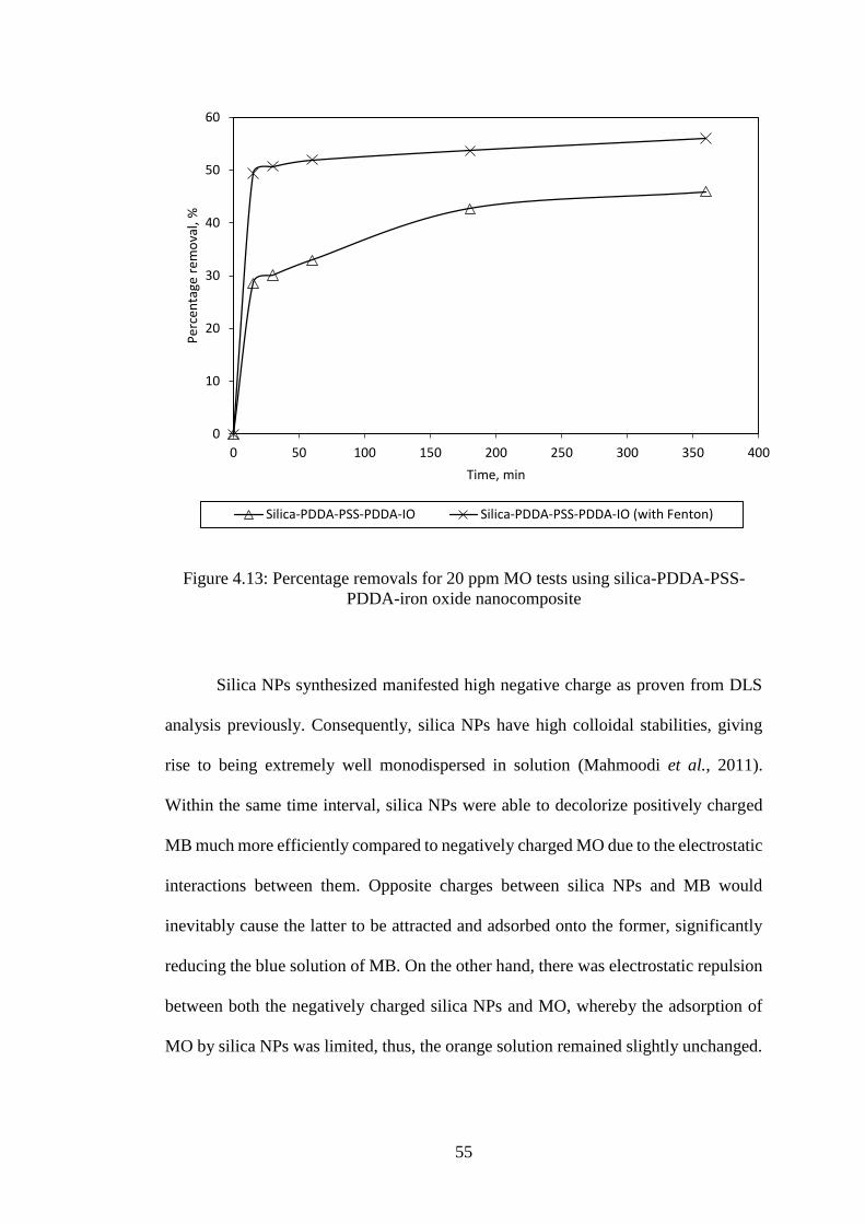
55
Figure 4.13: Percentage removals for 20 ppm MO tests using silica-PDDA-PSS-
PDDA-iron oxide nanocomposite
Silica NPs synthesized manifested high negative charge as proven from DLS
analysis previously. Consequently, silica NPs have high colloidal stabilities, giving
rise to being extremely well monodispersed in solution (Mahmoodi et al., 2011).
Within the same time interval, silica NPs were able to decolorize positively charged
MB much more efficiently compared to negatively charged MO due to the electrostatic
interactions between them. Opposite charges between silica NPs and MB would
inevitably cause the latter to be attracted and adsorbed onto the former, significantly
reducing the blue solution of MB. On the other hand, there was electrostatic repulsion
between both the negatively charged silica NPs and MO, whereby the adsorption of
MO by silica NPs was limited, thus, the orange solution remained slightly unchanged.
0
10
20
30
40
50
60
0 50 100 150 200 250 300 350 400
Per
cen
tage
rem
ova
l, %
Time, min
Silica-PDDA-PSS-PDDA-IO Silica-PDDA-PSS-PDDA-IO (with Fenton)
56
Subsequently, silica NPs were modified by having their surfaces coated with
positively charged polycations such as PDDA and PEI via electrostatic interaction as
well. The coating turned the silica-PDDA/PEI NPs highly positive, as a result, they
were able to remove negatively charged MO very effectively compared to positively
charged MB, simply due to the electrostatic attraction between the polymeric silica
and MO, and the electrostatic repulsion taking place between the polymeric silica and
MB. Hence, the orange MO was reduced tremendously while the blue MB remained
unchanged.
Then, the polymeric-modified silica core was again incorporated with
negatively charged iron oxide NPs, becoming the finished nanocomposites. At almost
neutral pH, nanocomposite analyzed by DLS showed an overall lower value of positive
charge, indicating that the negatively charged iron oxide NPs had suppressed the
highly positive charge of the polycations to have nanostructure of a lower net
magnitude of positive charge. So, being an anionic dye, MO could be decolorized
better compared to the cationic MB since MO was more preferably attracted and
adsorbed by the nanocomposite. Their MO removals were slightly less effective than
that of polymeric-modified silica core, since their counterparts have higher magnitudes
of positive charge resulting in stronger electrostatic attraction. However, MB could
still be decolorized slightly by the nanocomposite probably due to the ever-present
electrostatic attraction between the positive MB and the localized negatively charged
iron oxide NPs on the surface of nanocomposite.
However, without the addition of H2O2 reagent, it was just pure absorption
processes involved only. Once added, there would be an additional reaction plying its
trade called the Fenton reaction attributable to iron oxide NPs and the H2O2 reagent.
After the adsorption processes, MB and MO would be further catalytically degraded

57
by ∙OH decomposing from H2O2 on the catalyst surface where ∙OH is a nonspecific
oxidant reacting with most organic compounds, whereby both MB and MO would be
first adsorbed onto Fe3O4/FeMnOx before being decomposed by hydroxyl radical in
heterogeneous catalytic reaction processes (Xing et al., 2011). In other words, there
were two rounds of mechanisms playing their roles here. Once the adsorptive or the
binding sites were fully occupied by adsorption process, the remaining removals were
facilitated by the Fenton reaction processes. As a result, their removal efficiencies were
greatly enhanced as compared to their counterparts with only adsorption processes
involved. In addition, according to Che and coworkers (Che et al., 2014), these
nanocomposites are less susceptible to the thermal randomization energy compared to
individual particle and experience much greater magnetophoretic force to overcome
the viscous drag. These scenarios would enable rapid magnetic collection of
nanocomposite which composed of magnetic particle clusters after their usages in
water remediation, as evidenced by one of the tests done by Che and coworkers (Che
et al., 2014), where their finding implies that the ultimate nanocomposite has excellent
reusability and recyclability, making them a superior candidate for water treatment
purposes as they can always be used repeatedly and their performances are not
dependent on the charges of targeted pollutants alone (Che et al., 2014).
Taking silica-PDDA-iron oxide nanocomposite as an example, the pictorial
representation of its nanomaterial synthesized at each stage during dye-removing
processes is illustrated in Figure 4.14 below. For processes mainly driven by
adsorption such as those in (a) and (b), electrostatic interactions play important roles
in either promoting or suppressing the MB and MO removal depending on the charges
of adsorbate (dye molecules) and adsorbent (silica colloid and PDDA-coated silica
colloid). For silica-PDDA-iron oxide nanocomposite in process (c), the influence of
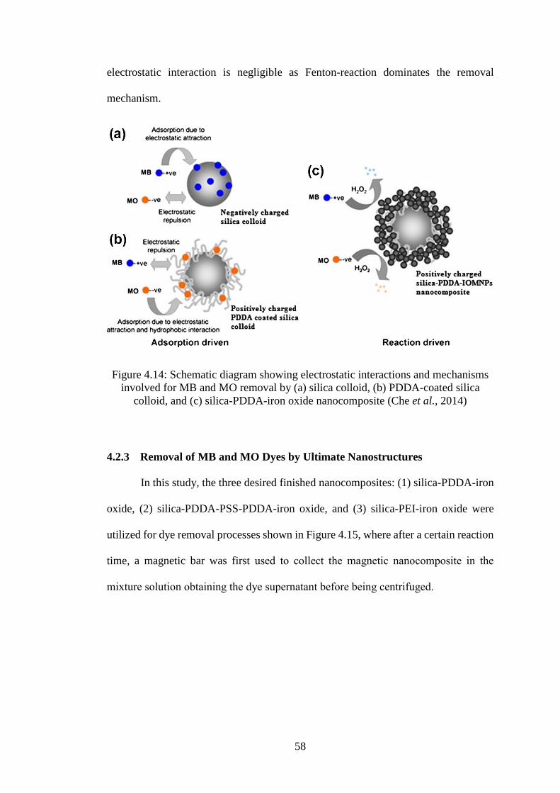
58
electrostatic interaction is negligible as Fenton-reaction dominates the removal
mechanism.
Figure 4.14: Schematic diagram showing electrostatic interactions and mechanisms
involved for MB and MO removal by (a) silica colloid, (b) PDDA-coated silica
colloid, and (c) silica-PDDA-iron oxide nanocomposite (Che et al., 2014)
4.2.3 Removal of MB and MO Dyes by Ultimate Nanostructures
In this study, the three desired finished nanocomposites: (1) silica-PDDA-iron
oxide, (2) silica-PDDA-PSS-PDDA-iron oxide, and (3) silica-PEI-iron oxide were
utilized for dye removal processes shown in Figure 4.15, where after a certain reaction
time, a magnetic bar was first used to collect the magnetic nanocomposite in the
mixture solution obtaining the dye supernatant before being centrifuged.
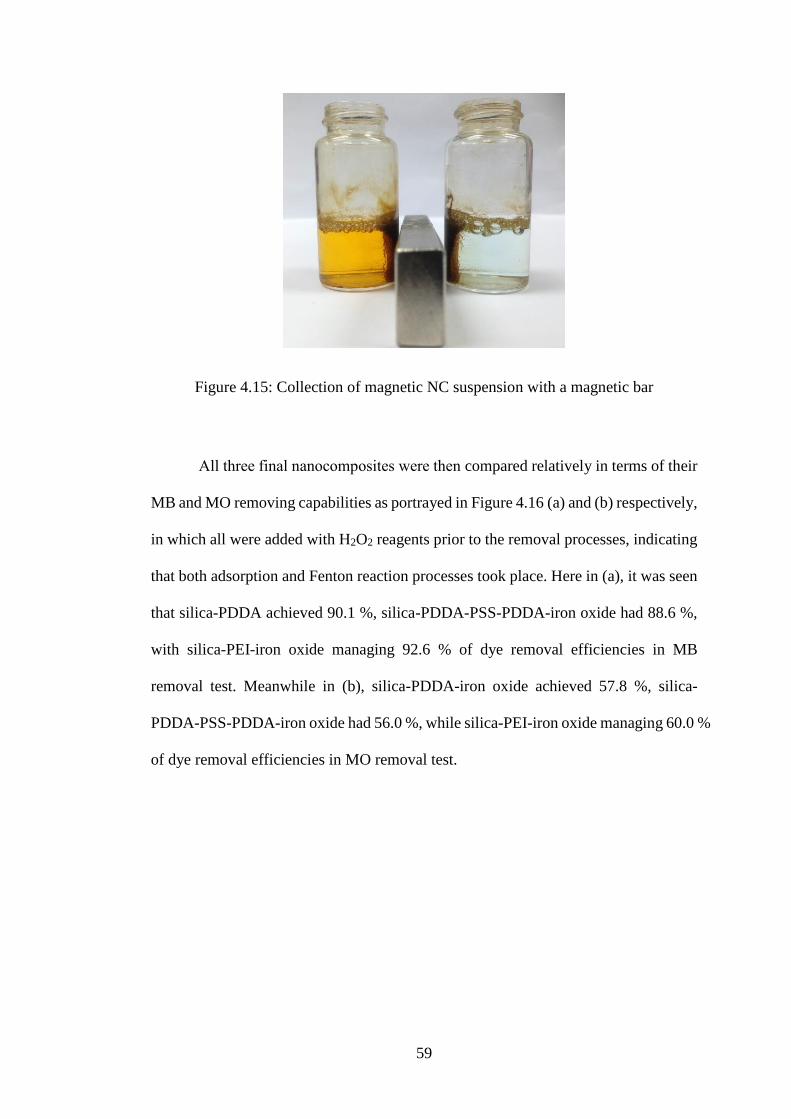
59
Figure 4.15: Collection of magnetic NC suspension with a magnetic bar
All three final nanocomposites were then compared relatively in terms of their
MB and MO removing capabilities as portrayed in Figure 4.16 (a) and (b) respectively,
in which all were added with H2O2 reagents prior to the removal processes, indicating
that both adsorption and Fenton reaction processes took place. Here in (a), it was seen
that silica-PDDA achieved 90.1 %, silica-PDDA-PSS-PDDA-iron oxide had 88.6 %,
with silica-PEI-iron oxide managing 92.6 % of dye removal efficiencies in MB
removal test. Meanwhile in (b), silica-PDDA-iron oxide achieved 57.8 %, silica-
PDDA-PSS-PDDA-iron oxide had 56.0 %, while silica-PEI-iron oxide managing 60.0 %
of dye removal efficiencies in MO removal test.
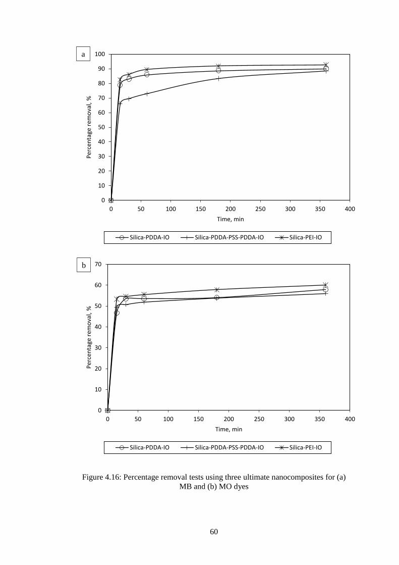
60
Figure 4.16: Percentage removal tests using three ultimate nanocomposites for (a)
MB and (b) MO dyes
0
10
20
30
40
50
60
70
80
90
100
0 50 100 150 200 250 300 350 400
Per
cen
tage
rem
ova
l, %
Time, min
Silica-PDDA-IO Silica-PDDA-PSS-PDDA-IO Silica-PEI-IO
a
0
10
20
30
40
50
60
70
0 50 100 150 200 250 300 350 400
Per
cen
tage
rem
ova
l, %
Time, min
Silica-PDDA-IO Silica-PDDA-PSS-PDDA-IO Silica-PEI-IO
b
61
Among all three synthesized nanocomposites, silica-PEI-iron oxide
nanocomposite had the highest percentage removal among all, while silica-PDDA-iron
oxide showed better efficiency than silica-PDDA-PSS-PDDA-iron oxide in both MB
and MO removals. From Figure 4.5 (a), there was only a thin single layer of PDDA
coated on silica core rather than the thick multilayers of polyelectrolytes seen in (b).
When there was only a single layer, the electrostatic barrier existing between the dyes
and nanocomposites was far less than that of multilayers. Since dyes needed to
penetrate through more layers in order to reach the core of the nanocomposites, it led
to the prerequisite of having to overcome higher electrostatic barriers, resulting in
lower dye removal performance for silica-PDDA-PSS-PDDA-iron oxide
nanocomposite despite having higher iron oxide content embedded on its surfaces in
Figure 4.5 (b) as compared to silica-PDDA-iron oxide shown in (a). Also, it is
understood that these multilayers were not assembled in an absolute-layered manner,
but they were in fact interpenetrable. This has inexorably given rise to the existence of
electroneutrality condition. Here, the local electroneutrality was assumed with the
electroneutrality balance having contributions from (Biesheuvel and Wittemann, 2005)
the alternatingly opposite charge of each layer of polyelectrolyte. Albeit these layers
were globally balanced to each other in terms of their charge distribution as one whole
layer adjacently, due to their interpenetrability however, they were not likely to be
locally balanced as well, causing them to experience imbalanced charge distribution,
where the dyes would have had to cope with these conditions every time they pass
through each layer. Without the imbalanced charge distribution experienced in the
single PDDA layered nanocomposite, the MB and MO particles would have less
obstacles or barriers to reach out for the core, indirectly increasing their dye removing
capabilities.

62
As for the silica-PEI-iron oxide nanocomposite illustrated by its structural
morphology in Figure 4.5 (c), it showed more irregularities in terms of its uniformity
of iron oxide NPs embedded as compared to (a) and (b). As mentioned, the
polyelectrolytes involved in (a) and (b) were all linear whereas PEI (c) was a branched
polycation. This difference in their structural configurations played essential roles in
the ways MO and MB dyes were being removed. It is clearly seen that the confinement
of iron oxide NPs onto the polymeric-silica matrices was almost similar between silica-
PDDA-PSS-PDDA-iron oxide and silica-PEI-iron oxide judging from the particle
distributions portrayed in Figure 4.5 (b) and (c). However, the key difference was that
not only the branching part of PEI was able to possess a much higher total surface area
to volume ratio, but to also own a more open fractal structure compared to its linear
counterparts. This fractal dynamics (Toroczkai et al., 1998) ineluctably brought to a
higher degree of voidness or openness in its nanostructure, resulting in a distribution
of iron oxide NPs that differs entirely from the formers that could degrade the dyes
more effectively in a way that its linear counterparts could not. Coupled with the fact
that this PEI layer registered was of single layer, it was no fluke that the dye removing
percentage efficiency of this type of configuration soared highest.

63
CHAPTER FIVE
CONCLUSION AND RECOMMENDATIONS
5.1 Conclusion
The synthesis of these revolutionary and sophisticated nanocomposites have
been destined to perform better as evidenced by the results and findings obtained, as
compared to their pure counterparts owing to their vastly enhanced functionalities
together with superior improvisations of their properties in a single unified
nanostructure, as these novel nanocomposites exhibit the best trait from each
nanomaterial. The highly monodispersed silica NPs aided in the stabilization of
composites in solution, diminishing their proneness to form lumps and clusters; while
polymeric networks surrounding the silica nanotemplate were responsible to entrap
dyes in a confined space, easing and fastening the removal processes and acting as
binding agents between the silica core and MIONPs by improving their physical
contacts; along with the magnetophoretic and catalytic bifunctionalities of iron oxide
NPs still being retained.
In this paper, two main agendas were focused on and studied. Firstly, the
mechanisms involved in dye removal processes which were the adsorption and
catalytic degradation processes; secondly, on how would the number of layers or
thickness of polyelectrolytes registered, and the difference in fractal dimension of
polymeric network, either linear or branched, influence the dye removal performance
of nanocomposites. Firstly, high removal efficiencies of MB by silica NPs and that of
MO by polyelectrolyte-modified silica NPs were dominated by electrostatic-driven
interactions, whereas the additional enhancements of dye removals by the ultimate
nanocomposites were contributed by Fenton and Fenton-like reactions facilitated by
iron oxide NPs and H2O2 reagent, catalytically degrading the dyes other than the
64
adsorption processes. Therefore, it is suggested that Fenton reactions have to be
involved for dye removal processes since during adsorption, the adsorptive sites are
always limited and will be saturated slowly but surely, and the pollutants will always
be retained within the polymeric matrix itself. Meanwhile during catalytic degradation,
iron oxides NPs are the active sites, can be used for multiple times and leaves no trace
of pollutants in its aftermath since they have already been degraded. In the second
highlight of this work, a single layer of PDDA and three multilayers of PDDA, PSS
and PDDA nanocomposites were respectively synthesized, where the former was more
effective in removing MO and MB dyes due to the less electrostatic barrier and less
imbalanced charge distribution experienced. Regarding the configurations of
polyelectrolytes employed, in which the more highly branched they are, the higher dye
removing capabilities they have because of their higher surface area to volume ratio
and their more open fractal structures, leading to a higher degree of voidness or
openness in the nanostructure. Thus, in a nutshell, with all the supported data and
findings, it is strongly validated that a single layered, branched polyelectrolyte will
make a far more interesting and superior nanocomposite, and hopefully, this will not
be merely a speculation.
65
5.2 Recommendations
These are some of the recommendations and suggestions that can be done to
further improvise and study the synthesis and application of nanocomposite.
1. Iron oxide NPs to be coated with polyelectrolytes prior being attached on silica
nanosphere surfaces rather than incorporating the iron oxide NPs only after the
silica NPs have been polyelectrolyte-modified.
2. More types of polyelectrolytes acting as the intermediate layer(s) to be
explored and employed in order to identify any branched polyelectrolytes with
better fractal dimension.
3. Reaction kinetics of nanocomposites for dye removal application to be studied
in order to have better insights on their underlying working mechanisms.

66
REFERENCES
Albanese, A., Sykes, E. A. & Chan, W. C. 2010. Rough around the edges: the
inflammatory response of microglial cells to spiky nanoparticles. ACS Nano,
4, 2490-2493.
Albornoz, C. & Jacobo, S. E. 2006. Preparation of a biocompatible magnetic film from
an aqueous ferrofluid. Journal of Magnetism and Magnetic Materials, 305, 12-
15.
Ambashta, R. D. & Sillanpää, M. 2010. Water purification using magnetic assistance:
a review. Journal of Hazardous Materials, 180, 38-49.
Asharani, P., Low Kah Mun, G., Hande, M. P. & Valiyaveettil, S. 2008. Cytotoxicity
and genotoxicity of silver nanoparticles in human cells. ACS Nano, 3, 279-290.
Barnakov, Y. A., Yu, M. H. & Rosenzweig, Z. 2005. Manipulation of the magnetic
properties of magnetite-silica nanocomposite materials by controlled Stober
synthesis. Langmuir, 21, 7524-7527.
Barnard, A. S. & Xu, H. 2008. An environmentally sensitive phase map of titania
nanocrystals. ACS Nano, 2, 2237-2242.
Becker, A. L., Johnston, A. P. & Caruso, F. 2010. Layer‐By‐Layer‐Assembled
Capsules and Films for Therapeutic Delivery. Small, 6.
Bek, A., Jansen, R., Ringler, M., Mayilo, S., Klar, T. A. & Feldmann, J. 2008.
Fluorescence enhancement in hot spots of AFM-designed gold nanoparticle
sandwiches. Nano Letters, 8, 485-490.
Bertrand, P., Jonas, A., Laschewsky, A. & Legras, R. 2000. Ultrathin polymer coatings
by complexation of polyelectrolytes at interfaces: suitable materials, structure
and properties. Macromolecular Rapid Communications, 21, 319-348.
Biesheuvel, P. M. & Wittemann, A. 2005. A modified box model including charge
regulation for protein adsorption in a spherical polyelectrolyte brush. The
Journal of Physical Chemistry B, 109, 4209-4214.
Bolto, B. A. 1990. Magnetic particle technology for wastewater treatment. Waste
Management, 10, 11-21.
Brillas, E., Calpe, J. C. & Casado, J. 2000. Mineralization of 2, 4-D by advanced
electrochemical oxidation processes. Water Research, 34, 2253-2262.
Bruening, M. L. & Adusumilli, M. Polyelectrolyte Multilayer Films and Membrane
Functionalization [Online]. Available:
http://www.sigmaaldrich.com/content/dam/sigma-aldrich/articles/material-
matters/pdf/polyelectrolyte-multilayer-films-and-membrane-
functionalization.pdf [Accessed 11th December 2013].
67
Bruening, M. L., Dotzauer, D. M., Jain, P., Ouyang, L. & Baker, G. L. 2008. Creation
of functional membranes using polyelectrolyte multilayers and polymer
brushes. Langmuir, 24, 7663-7673.
Bucak, S., Jones, D. A., Laibinis, P. E. & Hatton, T. A. 2003. Protein separations using
colloidal magnetic nanoparticles. Biotechnology Progress, 19, 477-484.
Buchholz, B., Nunez, L. & Vandegrift, G. F. 1996. Radiolysis and hydrolysis of
magnetically assisted chemical separation particles. Separation Science and
Technology, 31, 1933-1952.
Butter, K., Bomans, P., Frederik, P., Vroege, G. & Philipse, A. 2003. Direct
observation of dipolar chains in iron ferrofluids by cryogenic electron
microscopy. Nature Materials, 2, 88-91.
Capar, G., Yetis, U. & Yilmaz, L. 2006. Membrane based strategies for the pre-
treatment of acid dye bath wastewaters. Journal of Hazardous Materials, 135,
423-430.
Caruso, F. 2000. Hollow capsule processing through colloidal templating and self‐assembly. Chemistry-A European Journal, 6, 413-419.
Caruso, F., Caruso, R. A. & Möhwald, H. 1998a. Nanoengineering of inorganic and
hybrid hollow spheres by colloidal templating. Science, 282, 1111-1114.
Caruso, F., Donath, E. & Möhwald, H. 1998b. Influence of polyelectrolyte multilayer
coatings on Förster resonance energy transfer between 6-carboxyfluorescein
and rhodamine B-labeled particles in aqueous solution. The Journal of Physical
Chemistry B, 102, 2011-2016.
Caruso, F. & Möhwald, H. 1999. Preparation and characterization of ordered
nanoparticle and polymer composite multilayers on colloids. Langmuir, 15,
8276-8281.
Caruso, F., Niikura, K., Furlong, D. N. & Okahata, Y. 1997. Assembly of alternating
polyelectrolyte and protein multilayer films for immunosensing. Langmuir, 13,
3427-3433.
Caruso, F., Spasova, M., Susha, A., Giersig, M. & Caruso, R. A. 2001. Magnetic
nanocomposite particles and hollow spheres constructed by a sequential
layering approach. Chemistry of Materials, 13, 109-116.
Caruso, F., Susha, A. S., Giersig, M. & Möhwald, H. 1999. Magnetic CoreąShell
Particles: Preparation of Magnetite Multilayers on Polymer Latex
Microspheres. Adv. Mater, 11.
Casals, E., Pfaller, T., Duschl, A., Oostingh, G. J. & Puntes, V. 2010. Time evolution
of the nanoparticle protein corona. ACS Nano, 4, 3623-3632.
Casals, E., Vázquez-Campos, S., Bastús, N. G. & Puntes, V. 2008. Distribution and
potential toxicity of engineered inorganic nanoparticles and carbon

68
nanostructures in biological systems. TrAC Trends in Analytical Chemistry, 27,
672-683.
Chang, E., Thekkek, N., Yu, W. W., Colvin, V. L. & Drezek, R. 2006. Evaluation of
quantum dot cytotoxicity based on intracellular uptake. Small, 2, 1412-1417.
Chang, S.-C., Anderson, T. I., Bahrman, S. E., Gruden, C. L., Khijniak, A. I. &
Adriaens, P. 2005. Comparing recovering efficiency of immunomagnetic
separation and centrifugation of mycobacteria in metalworking fluids. Journal
of Industrial Microbiology and Biotechnology, 32, 629-638.
Che, H. X., Yeap, S. P., Ahmad, A. L. & Lim, J. 2014. Layer-by-layer assembly of
iron oxide magnetic nanoparticles decorated silica colloid for water
remediation. Chemical Engineering Journal.
Chin, A. B. & Yaacob, I. I. 2007. Synthesis and characterization of magnetic iron oxide
nanoparticles via w/o microemulsion and Massart's procedure. Journal of
Materials Processing Technology, 191, 235-237.
Chiou, M.-S., Ho, P.-Y. & Li, H.-Y. 2004. Adsorption of anionic dyes in acid solutions
using chemically cross-linked chitosan beads. Dyes and Pigments, 60, 69-84.
Cotten, G. B. & Eldredge, H. B. 2002. Nanolevel magnetic separation model
considering flow limitations. Separation Science and Technology, 37, 3755-
3779.
Daughton, C. G. 2004. Non-regulated water contaminants: emerging research.
Environmental Impact Assessment Review, 24, 711-732.
De Gennes, P. & Pincus, P. 1970. Pair correlations in a ferromagnetic colloid. Physik
der kondensierten Materie, 11, 189-198.
De Laat, J. & Gallard, H. 1999. Catalytic decomposition of hydrogen peroxide by Fe
(III) in homogeneous aqueous solution: mechanism and kinetic modeling.
Environmental Science and Technology, 33, 2726-2732.
De Souza, D. R., Duarte, E. T. F. M., De Souza Girardi, G., Velani, V., Da Hora
Machado, A. E., Sattler, C., De Oliveira, L. & De Miranda, J. A. 2006. Study
of kinetic parameters related to the degradation of an industrial effluent using
Fenton-like reactions. Journal of Photochemistry and Photobiology A:
Chemistry, 179, 269-275.
De Vicente, J., Delgado, A., Plaza, R., Durán, J. & González-Caballero, F. 2000.
Stability of cobalt ferrite colloidal particles. Effect of pH and applied magnetic
fields. Langmuir, 16, 7954-7961.
Decher, G. 1997. Fuzzy nanoassemblies: toward layered polymeric multicomposites.
Science, 277, 1232-1237.
Decher, G., Hong, J. & Schmitt, J. 1992. Buildup of ultrathin multilayer films by a
self-assembly process: III. Consecutively alternating adsorption of anionic and
cationic polyelectrolytes on charged surfaces. Thin Solid Films, 210, 831-835.
69
Decher, G. & Hong, J. D. Buildup of ultrathin multilayer films by a self‐assembly
process, 1 consecutive adsorption of anionic and cationic bipolar amphiphiles
on charged surfaces. Makromolekulare Chemie. Macromolecular Symposia,
1991. Wiley Online Library, 321-327.
Deng, Y., Deng, C., Qi, D., Liu, C., Liu, J., Zhang, X. & Zhao, D. 2009. Synthesis of
core/shell colloidal magnetic zeolite microspheres for the immobilization of
trypsin. Advanced Materials, 21, 1377-1382.
Donath, E., Sukhorukov, G. B., Caruso, F., Davis, S. A. & Möhwald, H. 1998. Novel
hollow polymer shells by colloid‐templated assembly of polyelectrolytes.
Angewandte Chemie International Edition, 37, 2201-2205.
Dotzauer, D. M., Dai, J., Sun, L. & Bruening, M. L. 2006. Catalytic membranes
prepared using layer-by-layer adsorption of polyelectrolyte/metal nanoparticle
films in porous supports. Nano Letters, 6, 2268-2272.
Dutta, K., Mukhopadhyay, S., Bhattacharjee, S. & Chaudhuri, B. 2001. Chemical
oxidation of methylene blue using a Fenton-like reaction. Journal of
Hazardous Materials, 84, 57-71.
Faraji, M., Yamini, Y. & Rezaee, M. 2010. Magnetic nanoparticles: synthesis,
stabilization, functionalization, characterization, and applications. Journal of
the Iranian Chemical Society, 7, 1-37.
Faust, B. C. & Hoigne, J. 1990. Photolysis of Fe (III)-hydroxy complexes as sources
of OH radicals in clouds, fog and rain. Atmospheric Environment. Part A.
General Topics, 24, 79-89.
Feng, J., Hu, X., Yue, P. L., Zhu, H. Y. & Lu, G. Q. 2003. Degradation of azo-dye
orange II by a photoassisted Fenton reaction using a novel composite of iron
oxide and silicate nanoparticles as a catalyst. Industrial and Engineering
Chemistry Research, 42, 2058-2066.
Fornara, A., Johansson, P., Petersson, K., Gustafsson, S., Qin, J., Olsson, E., Ilver, D.,
Krozer, A., Muhammed, M. & Johansson, C. 2008. Tailored magnetic
nanoparticles for direct and sensitive detection of biomolecules in biological
samples. Nano Letters, 8, 3423-3428.
Furusawa, K., Nagashima, K. & Anzai, C. 1994. Synthetic process to control the total
size and component distribution of multilayer magnetic composite particles.
Colloid and Polymer Science, 272, 1104-1110.
Gao, Y., Pu, X., Zhang, D., Ding, G., Shao, X. & Ma, J. 2012. Combustion synthesis
of graphene oxide-TiO2 hybrid materials for photodegradation of methyl
orange. Carbon, 50, 4093-4101.
George, S., Pokhrel, S., Xia, T., Gilbert, B., Ji, Z., Schowalter, M., Rosenauer, A.,
Damoiseaux, R., Bradley, K. A. & MaDler, L. 2009. Use of a rapid cytotoxicity
screening approach to engineer a safer zinc oxide nanoparticle through iron
doping. ACS Nano, 4, 15-29.
70
Gerber, R. & Birss, R. R. 1983. High gradient magnetic separation, Research Studies
Press London.
Gijs, M. A., Lacharme, F. & Lehmann, U. 2009. Microfluidic applications of magnetic
particles for biological analysis and catalysis. Chemical Reviews, 110, 1518-
1563.
Gözmen, B., Oturan, M. A., Oturan, N. & Erbatur, O. 2003. Indirect electrochemical
treatment of bisphenol A in water via electrochemically generated Fenton's
reagent. Environmental Science and Technology, 37, 3716-3723.
Hee Kim, E., Sook Lee, H., Kook Kwak, B. & Kim, B.-K. 2005. Synthesis of ferrofluid
with magnetic nanoparticles by sonochemical method for MRI contrast agent.
Journal of Magnetism and Magnetic Materials, 289, 328-330.
Henn, K. W. & Waddill, D. W. 2006. Utilization of nanoscale zero‐valent iron for
source remediation-A case study. Remediation Journal, 16, 57-77.
Hess, H. & Tseng, Y. 2007. Active intracellular transport of nanoparticles: opportunity
or threat? ACS Nano, 1, 390-392.
Hirschbein, B. L., Brown, D. W. & Whitesides, G. M. 1982. Magnetic separations in
chemistry and biochemistry. Chemtech, 12, 172-179.
Hoda, N. & Larson, R. G. 2009. Modeling the buildup of exponentially growing
polyelectrolyte multilayer films. The Journal of Physical Chemistry B, 113,
4232-4241.
Hu, J., Lo, I. & Chen, G. 2004. Removal of Cr (VI) by magnetite. Water Science and
Technology, 50, 139-146.
Hubbuch, J. J. & Thomas, O. R. 2002. High‐gradient magnetic affinity separation of
trypsin from porcine pancreatin. Biotechnology and Bioengineering, 79, 301-
313.
Hutter, E., Boridy, S., Labrecque, S., Lalancette-Hébert, M., Kriz, J., Winnik, F. M. &
Maysinger, D. 2010. Microglial response to gold nanoparticles. ACS Nano, 4,
2595-2606.
Illés, E. & Tombácz, E. 2006. The effect of humic acid adsorption on pH-dependent
surface charging and aggregation of magnetite nanoparticles. Journal of
Colloid and Interface Science, 295, 115-123.
Im, S. H., Herricks, T., Lee, Y. T. & Xia, Y. 2005. Synthesis and characterization of
monodisperse silica colloids loaded with superparamagnetic iron oxide
nanoparticles. Chemical Physics Letters, 401, 19-23.
Jang, J. 2006. Conducting polymer nanomaterials and their applications. Emissive
Materials Nanomaterials. Springer.
71
Jenekhe, S. A. & Chen, X. L. 1998. Self-assembled aggregates of rod-coil block
copolymers and their solubilization and encapsulation of fullerenes. Science,
279, 1903-1907.
Jeong, Y. S., Oh, W.-K., Kim, S. & Jang, J. 2011. Cellular uptake, cytotoxicity, and
ROS generation with silica/conducting polymer core/shell nanospheres.
Biomaterials, 32, 7217-7225.
Jiang, C., Pang, S., Ouyang, F., Ma, J. & Jiang, J. 2010. A new insight into Fenton and
Fenton-like processes for water treatment. Journal of Hazardous Materials,
174, 813-817.
Jiang, R., Fu, Y. Q., Zhu, H. Y., Yao, J. & Xiao, L. 2012. Removal of methyl orange
from aqueous solutions by magnetic maghemite/chitosan nanocomposite films:
adsorption kinetics and equilibrium. Journal of Applied Polymer Science, 125,
E540-E549.
Josephson, L., Perez, J. M. & Weissleder, R. 2001. Magnetic nanosensors for the
detection of oligonucleotide sequences. Angewandte Chemie, 113, 3304-3306.
Kaminski, M. & Nunez, L. 1999. Extractant-coated magnetic particles for cobalt and
nickel recovery from acidic solution. Journal of Magnetism and Magnetic
Materials, 194, 31-36.
Karcher, S., Kornmüller, A. & Jekel, M. 2002. Anion exchange resins for removal of
reactive dyes from textile wastewaters. Water Research, 36, 4717-4724.
Karumanchi, R. S., Doddamane, S. N., Sampangi, C. & Todd, P. W. 2002. Field-
assisted extraction of cells, particles and macromolecules. TRENDS in
Biotechnology, 20, 72-78.
Kashiwada, S. 2006. Distribution of nanoparticles in the see-through medaka (Oryzias
latipes). Environmental Health Perspectives, 114, 1697.
Kirchner, C., Liedl, T., Kudera, S., Pellegrino, T., Muñoz Javier, A., Gaub, H. E.,
Stölzle, S., Fertig, N. & Parak, W. J. 2005. Cytotoxicity of colloidal CdSe and
CdSe/ZnS nanoparticles. Nano Letters, 5, 331-338.
Kornaros, M. & Lyberatos, G. 2006. Biological treatment of wastewaters from a dye
manufacturing company using a trickling filter. Journal of Hazardous
Materials, 136, 95-102.
Kuo, W. 1992. Decolorizing dye wastewater with Fenton's reagent. Water Research,
26, 881-886.
Kusvuran, E., Irmak, S., Yavuz, H. I., Samil, A. & Erbatur, O. 2005. Comparison of
the treatment methods efficiency for decolorization and mineralization of
Reactive Black 5 azo dye. Journal of Hazardous Materials, 119, 109-116.
Langer, R. & Chasin, M. 1990. Biodegradable polymers as drug delivery systems.
Marcel Dekker, New York.
72
Lasic, D. D. 1993. Liposomes: from physics to applications, Elsevier Amsterdam etc.
Laurent, S., Forge, D., Port, M., Roch, A., Robic, C., Vander Elst, L. & Muller, R. N.
2008. Magnetic iron oxide nanoparticles: synthesis, stabilization, vectorization,
physicochemical characterizations, and biological applications. Chemical
Reviews, 108, 2064-2110.
Lavalle, P., Picart, C., Mutterer, J., Gergely, C., Reiss, H., Voegel, J.-C., Senger, B. &
Schaaf, P. 2004. Modeling the Buildup of Polyelectrolyte Multilayer Films
Having Exponential Growth x. The Journal of Physical Chemistry B, 108, 635-
648.
Lee, H., Kepley, L. J., Hong, H. G., Akhter, S. & Mallouk, T. E. 1988. Adsorption of
ordered zirconium phosphonate multilayer films on silicon and gold surfaces.
The Journal of Physical Chemistry, 92, 2597-2601.
Lee, J., Mahendra, S. & Alvarez, P. J. 2010. Nanomaterials in the construction industry:
a review of their applications and environmental health and safety
considerations. ACS Nano, 4, 3580-3590.
Lee, K., Lee, H., Lee, K. W. & Park, T. G. 2011. Optical imaging of intracellular
reactive oxygen species for the assessment of the cytotoxicity of nanoparticles.
Biomaterials, 32, 2556-2565.
Lee, S.-J., Jeong, J.-R., Shin, S.-C., Kim, J.-C. & Kim, J.-D. 2004. Synthesis and
characterization of superparamagnetic maghemite nanoparticles prepared by
coprecipitation technique. Journal of Magnetism and Magnetic Materials, 282,
147-150.
Lesnikovich, A., Shunkevich, T., Naumenko, V., Vorobyova, S. & Baykov, M. 1990.
Dispersity of magnetite in magnetic liquids and the interaction with a surfactant.
Journal of Magnetism and Magnetic Materials, 85, 14-16.
Leun, D. & Sengupta, A. K. 2000. Preparation and characterization of magnetically
active polymeric particles (MAPPs) for complex environmental separations.
Environmental Science and Technology, 34, 3276-3282.
Lewinski, N., Colvin, V. & Drezek, R. 2008. Cytotoxicity of nanoparticles. Small, 4,
26-49.
Li, H., Gao, S., Zheng, Z. & Cao, R. 2011. Bifunctional composite prepared using
layer-by-layer assembly of polyelectrolyte-gold nanoparticle films on Fe3O4-
silica core-shell microspheres. Catalysis Science and Technology, 1, 1194-
1201.
Lim, J., Lanni, C., Evarts, E. R., Lanni, F., Tilton, R. D. & Majetich, S. A. 2010.
Magnetophoresis of nanoparticles. ACS Nano, 5, 217-226.
Lim, J. K., Majetich, S. A. & Tilton, R. D. 2009. Stabilization of Superparamagnetic
Iron Oxide Core-Gold Shell Nanoparticles in High Ionic Strength Media.
Langmuir, 25, 13384-13393.
73
Limbach, L. K., Bereiter, R., MuLler, E., Krebs, R., GaLli, R. & Stark, W. J. 2008.
Removal of oxide nanoparticles in a model wastewater treatment plant:
influence of agglomeration and surfactants on clearing efficiency.
Environmental Science and Technology, 42, 5828-5833.
Liu, S., Wei, L., Hao, L., Fang, N., Chang, M. W., Xu, R., Yang, Y. & Chen, Y. 2009.
Sharper and faster “nano darts” kill more bacteria: a study of antibacterial
activity of individually dispersed pristine single-walled carbon nanotube. ACS
Nano, 3, 3891-3902.
Lvov, Y., Ariga, K., Onda, M., Ichinose, I. & Kunitake, T. 1997. Alternate assembly
of ordered multilayers of SiO2 and other nanoparticles and polyions. Langmuir,
13, 6195-6203.
Ma, H., Zhuo, Q. & Wang, B. 2009. Electro-catalytic degradation of methylene blue
wastewater assisted by Fe2O3-modified kaolin. Chemical Engineering Journal,
155, 248-253.
Mahmoodi, N. M., Khorramfar, S. & Najafi, F. 2011. Amine-functionalized silica
nanoparticle: Preparation, characterization and anionic dye removal ability.
Desalination, 279, 61-68.
Mahmoudi, M., Sant, S., Wang, B., Laurent, S. & Sen, T. 2011. Superparamagnetic
iron oxide nanoparticles (SPIONs): development, surface modification and
applications in chemotherapy. Advanced Drug Delivery Reviews, 63, 24-46.
Mann, S. 2009. Self-assembly and transformation of hybrid nano-objects and
nanostructures under equilibrium and non-equilibrium conditions. Nature
Materials, 8, 781-792.
Maoz, R., Netzer, L., Gun, J. & Sagiv, J. 1988. Self-assembling monolayers in the
construction of planned supramolecular structures and as modifiers of surface
properties. J. Chim. Phys, 85, 1059-1064.
Martínez-Mera, I., Espinosa-Pesqueira, M., Pérez-Hernández, R. & Arenas-Alatorre,
J. 2007. Synthesis of magnetite (Fe3O4) nanoparticles without surfactants at
room temperature. Materials Letters, 61, 4447-4451.
Mathew, D. S. & Juang, R.-S. 2007. An overview of the structure and magnetism of
spinel ferrite nanoparticles and their synthesis in microemulsions. Chemical
Engineering Journal, 129, 51-65.
Matsumoto, H., Nagao, D. & Konno, M. 2009. Repetitive heterocoagulation of
oppositely charged particles for enhancement of magnetic nanoparticle loading
into monodisperse silica particles. Langmuir, 26, 4207-4211.
Matta, R., Hanna, K. & Chiron, S. 2007. Fenton-like oxidation of 2, 4, 6-trinitrotoluene
using different iron minerals. Science of the Total Environment, 385, 242-251.
Maurer-Jones, M. A., Lin, Y.-S. & Haynes, C. L. 2010. Functional assessment of metal
oxide nanoparticle toxicity in immune cells. ACS Nano, 4, 3363-3373.

74
Mccarthy, J. R. & Weissleder, R. 2008. Multifunctional magnetic nanoparticles for
targeted imaging and therapy. Advanced Drug Delivery Reviews, 60, 1241-
1251.
Mccloskey, K. E., Chalmers, J. J. & Zborowski, M. 2003. Magnetic cell separation:
characterization of magnetophoretic mobility. Analytical Chemistry, 75, 6868-
6874.
Meng, H., Xia, T., George, S. & Nel, A. E. 2009. A predictive toxicological paradigm
for the safety assessment of nanomaterials. ACS Nano, 3, 1620-1627.
Merrifield, R. 1965. Automated synthesis of peptides. Science, 150, 178-185.
Miyawaki, J., Yudasaka, M., Azami, T., Kubo, Y. & Iijima, S. 2008. Toxicity of
single-walled carbon nanohorns. ACS Nano, 2, 213-226.
Moeser, G. D., Roach, K. A., Green, W. H., Alan Hatton, T. & Laibinis, P. E. 2004.
High‐gradient magnetic separation of coated magnetic nanoparticles. AIChE
Journal, 50, 2835-2848.
Moeser, G. D., Roach, K. A., Green, W. H., Laibinis, P. E. & Hatton, T. A. 2002.
Water-based magnetic fluids as extractants for synthetic organic compounds.
Industrial and Engineering Chemistry Research, 41, 4739-4749.
Moore, M. 2006. Do nanoparticles present ecotoxicological risks for the health of the
aquatic environment? Environment International, 32, 967-976.
Morrison, S. A., Cahill, C. L., Carpenter, E. E., Calvin, S. & Harris, V. G. 2005.
Atomic engineering of mixed ferrite and core-shell nanoparticles. Journal of
Nanoscience and Nanotechnology, 5, 1323-1344.
Murphy, A. P., Boegli, W. J., Price, M. K. & Moody, C. D. 1989. A Fenton-like
reaction to neutralize formaldehyde waste solutions. Environmental Science
and Technology, 23, 166-169.
Murray, C. & Parsons, S. 2004. Comparison of AOPs for the removal of natural
organic matter: performance and economic assessment. Water Science and
Technology, 49, 267-272.
Nabeshi, H., Yoshikawa, T., Matsuyama, K., Nakazato, Y., Matsuo, K., Arimori, A.,
Isobe, M., Tochigi, S., Kondoh, S. & Hirai, T. 2011. Systemic distribution,
nuclear entry and cytotoxicity of amorphous nanosilica following topical
application. Biomaterials, 32, 2713-2724.
Nativo, P., Prior, I. A. & Brust, M. 2008. Uptake and intracellular fate of surface-
modified gold nanoparticles. ACS Nano, 2, 1639-1644.
Navarro, E., Baun, A., Behra, R., Hartmann, N. B., Filser, J., Miao, A.-J., Quigg, A.,
Santschi, P. H. & Sigg, L. 2008. Environmental behavior and ecotoxicity of
engineered nanoparticles to algae, plants, and fungi. Ecotoxicology, 17, 372-
386.

75
Nel, A., Xia, T., Mädler, L. & Li, N. 2006. Toxic potential of materials at the nanolevel.
Science, 311, 622-627.
Neyens, E. & Baeyens, J. 2003. A review of classic Fenton’s peroxidation as an
advanced oxidation technique. Journal of Hazardous Materials, 98, 33-50.
Nowack, B. & Bucheli, T. D. 2007. Occurrence, behavior and effects of nanoparticles
in the environment. Environmental Pollution, 150, 5-22.
Oh, W.-K., Kim, S., Choi, M., Kim, C., Jeong, Y. S., Cho, B.-R., Hahn, J.-S. & Jang,
J. 2010. Cellular uptake, cytotoxicity, and innate immune response of silica-
titania hollow nanoparticles based on size and surface functionality. ACS Nano,
4, 5301-5313.
Parida, S. K., Dash, S., Patel, S. & Mishra, B. 2006. Adsorption of organic molecules
on silica surface. Advances in Colloid and Interface Science, 121, 77-110.
Phenrat, T., Saleh, N., Sirk, K., Tilton, R. D. & Lowry, G. V. 2007. Aggregation and
sedimentation of aqueous nanoscale zerovalent iron dispersions.
Environmental Science and Technology, 41, 284-290.
Pignatello, J. J. 1992. Dark and photoassisted iron (3+)-catalyzed degradation of
chlorophenoxy herbicides by hydrogen peroxide. Environmental Science and
Technology, 26, 944-951.
Poland, C. A., Duffin, R., Kinloch, I., Maynard, A., Wallace, W. A., Seaton, A., Stone,
V., Brown, S., Macnee, W. & Donaldson, K. 2008. Carbon nanotubes
introduced into the abdominal cavity of mice show asbestos-like pathogenicity
in a pilot study. Nature Nanotechnology, 3, 423-428.
Pons, T., Pic, E., Lequeux, N., Cassette, E., Bezdetnaya, L., Guillemin, F., Marchal, F.
& Dubertret, B. 2010. Cadmium-free CuInS2/ZnS quantum dots for sentinel
lymph node imaging with reduced toxicity. ACS Nano, 4, 2531-2538.
Promislow, J. H., Gast, A. P. & Fermigier, M. 1995. Aggregation kinetics of
paramagnetic colloidal particles. The Journal of Chemical Physics, 102, 5492.
Quinn, J. F., Johnston, A. P., Such, G. K., Zelikin, A. N. & Caruso, F. 2007. Next
generation, sequentially assembled ultrathin films: beyond electrostatics.
Chemical Society Reviews, 36, 707-718.
Razo-Flores, E., Luijten, M., Donlon, B., Lettinga, G. & Field, J. 1997. Biodegradation
of selected azo dyes under methanogenic conditions. Water Science and
Technology, 36, 65-72.
Reed, B. E., Matsumoto, M. R., Jensen, J. N., Viadero, R. & Lin, W. 1998.
Physicochemical processes. Water Environment Research, 70, 449-473.
Rivera Gil, P., OberdöRster, G. N., Elder, A., Puntes, V. C. & Parak, W. J. 2010.
Correlating physico-chemical with toxicological properties of nanoparticles:
the present and the future. ACS Nano, 4, 5527-5531.
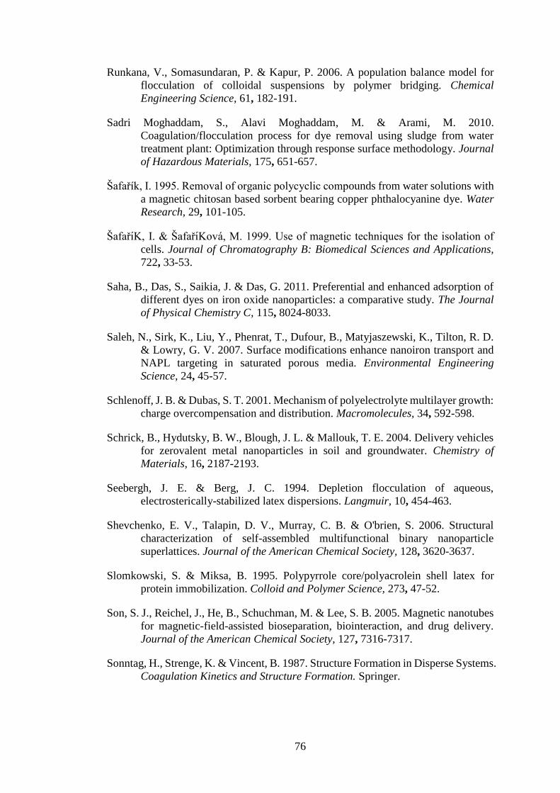
76
Runkana, V., Somasundaran, P. & Kapur, P. 2006. A population balance model for
flocculation of colloidal suspensions by polymer bridging. Chemical
Engineering Science, 61, 182-191.
Sadri Moghaddam, S., Alavi Moghaddam, M. & Arami, M. 2010.
Coagulation/flocculation process for dye removal using sludge from water
treatment plant: Optimization through response surface methodology. Journal
of Hazardous Materials, 175, 651-657.
Šafařík, I. 1995. Removal of organic polycyclic compounds from water solutions with
a magnetic chitosan based sorbent bearing copper phthalocyanine dye. Water
Research, 29, 101-105.
ŠafařıK, I. & ŠafařıKová, M. 1999. Use of magnetic techniques for the isolation of
cells. Journal of Chromatography B: Biomedical Sciences and Applications,
722, 33-53.
Saha, B., Das, S., Saikia, J. & Das, G. 2011. Preferential and enhanced adsorption of
different dyes on iron oxide nanoparticles: a comparative study. The Journal
of Physical Chemistry C, 115, 8024-8033.
Saleh, N., Sirk, K., Liu, Y., Phenrat, T., Dufour, B., Matyjaszewski, K., Tilton, R. D.
& Lowry, G. V. 2007. Surface modifications enhance nanoiron transport and
NAPL targeting in saturated porous media. Environmental Engineering
Science, 24, 45-57.
Schlenoff, J. B. & Dubas, S. T. 2001. Mechanism of polyelectrolyte multilayer growth:
charge overcompensation and distribution. Macromolecules, 34, 592-598.
Schrick, B., Hydutsky, B. W., Blough, J. L. & Mallouk, T. E. 2004. Delivery vehicles
for zerovalent metal nanoparticles in soil and groundwater. Chemistry of
Materials, 16, 2187-2193.
Seebergh, J. E. & Berg, J. C. 1994. Depletion flocculation of aqueous,
electrosterically-stabilized latex dispersions. Langmuir, 10, 454-463.
Shevchenko, E. V., Talapin, D. V., Murray, C. B. & O'brien, S. 2006. Structural
characterization of self-assembled multifunctional binary nanoparticle
superlattices. Journal of the American Chemical Society, 128, 3620-3637.
Slomkowski, S. & Miksa, B. 1995. Polypyrrole core/polyacrolein shell latex for
protein immobilization. Colloid and Polymer Science, 273, 47-52.
Son, S. J., Reichel, J., He, B., Schuchman, M. & Lee, S. B. 2005. Magnetic nanotubes
for magnetic-field-assisted bioseparation, biointeraction, and drug delivery.
Journal of the American Chemical Society, 127, 7316-7317.
Sonntag, H., Strenge, K. & Vincent, B. 1987. Structure Formation in Disperse Systems.
Coagulation Kinetics and Structure Formation. Springer.

77
Stöber, W., Fink, A. & Bohn, E. 1968. Controlled growth of monodisperse silica
spheres in the micron size range. Journal of Colloid and Interface Science, 26,
62-69.
Sukhorukov, G., Möhwald, H., Decher, G. & Lvov, Y. M. 1996. Assembly of
polyelectrolyte multilayer films by consecutively alternating adsorption of
polynucleotides and polycations. Thin Solid Films, 284, 220-223.
Sun, Y.-P., Li, X.-Q., Cao, J., Zhang, W.-X. & Wang, H. P. 2006. Characterization of
zero-valent iron nanoparticles. Advances in Colloid and Interface Science, 120,
47-56.
Sun, Y., Duan, L., Guo, Z., Duanmu, Y., Ma, M., Xu, L., Zhang, Y. & Gu, N. 2005.
An improved way to prepare superparamagnetic magnetite-silica core-shell
nanoparticles for possible biological application. Journal of Magnetism and
Magnetic Materials, 285, 65-70.
Taylor, J. I., Hurst, C. D., Davies, M. J., Sachsinger, N. & Bruce, I. J. 2000.
Application of magnetite and silica-magnetite composites to the isolation of
genomic DNA. Journal of Chromatography A, 890, 159-166.
Thubagere, A. & Reinhard, B. R. M. 2010. Nanoparticle-induced apoptosis propagates
through hydrogen-peroxide-mediated bystander killing: insights from a human
intestinal epithelium in vitro model. ACS Nano, 4, 3611-3622.
Toroczkai, Z., Károlyi, G., Péntek, Á., Tél, T. & Grebogi, C. 1998. Advection of active
particles in open chaotic flows. Physical Review Letters, 80, 500.
Tratnyek, P. G. & Johnson, R. L. 2006. Nanotechnologies for environmental cleanup.
Nano Today, 1, 44-48.
Vatta, L. L., Sanderson, R. D. & Koch, K. R. 2006. Magnetic nanoparticles: Properties
and potential applications. Pure and Applied Chemistry, 78, 1793-1801.
Walczyk, D., Bombelli, F. B., Monopoli, M. P., Lynch, I. & Dawson, K. A. 2010.
What the cell “sees” in bionanoscience. Journal of the American Chemical
Society, 132, 5761-5768.
Watts, R. J., Bottenberg, B. C., Hess, T. F., Jensen, M. D. & Teel, A. L. 1999. Role of
reductants in the enhanced desorption and transformation of chloroaliphatic
compounds by modified Fenton's reactions. Environmental Science and
Technology, 33, 3432-3437.
Wu, F.-C. & Tseng, R.-L. 2008. High adsorption capacity NaOH-activated carbon for
dye removal from aqueous solution. Journal of Hazardous Materials, 152,
1256-1267.
Wu, W., He, Q. & Jiang, C. 2008. Magnetic iron oxide nanoparticles: synthesis and
surface functionalization strategies. Nanoscale Research Letters, 3, 397-415.
Xia, T., Kovochich, M., Liong, M., MaDler, L., Gilbert, B., Shi, H., Yeh, J. I., Zink, J.
I. & Nel, A. E. 2008. Comparison of the mechanism of toxicity of zinc oxide

78
and cerium oxide nanoparticles based on dissolution and oxidative stress
properties. ACS Nano, 2, 2121-2134.
Xing, S., Zhou, Z., Ma, Z. & Wu, Y. 2011. Characterization and reactivity of
Fe3O4/FeMnOx core/shell nanoparticles for methylene blue discoloration with
H2O2. Applied Catalysis B: Environmental, 107, 386-392.
Xu, H., Cui, L., Tong, N. & Gu, H. 2006. Development of high magnetization
Fe3O4/polystyrene/silica nanospheres via combined miniemulsion/emulsion
polymerization. Journal of the American Chemical Society, 128, 15582-15583.
Yang, S., He, H., Wu, D., Chen, D., Ma, Y., Li, X., Zhu, J. & Yuan, P. 2009.
Degradation of methylene blue by heterogeneous Fenton reaction using
titanomagnetite at neutral pH values: process and affecting factors. Industrial
and Engineering Chemistry Research, 48, 9915-9921.
Yavuz, C. T., Mayo, J., William, W. Y., Prakash, A., Falkner, J. C., Yean, S., Cong,
L., Shipley, H. J., Kan, A. & Tomson, M. 2006. Low-field magnetic separation
of monodisperse Fe3O4 nanocrystals. Science, 314, 964-967.
Yeap, S. P., Ahmad, A. L., Ooi, B. S. & Lim, J. 2012. Electrosteric stabilization and
its role in cooperative magnetophoresis of colloidal magnetic nanoparticles.
Langmuir, 28, 14878-14891.
Zazo, J., Casas, J., Mohedano, A., Gilarranz, M. & Rodriguez, J. 2005. Chemical
pathway and kinetics of phenol oxidation by Fenton's reagent. Environmental
Science and Technology, 39, 9295-9302.
Zhao, M., Sun, L. & Crooks, R. M. 1998. Preparation of Cu nanoclusters within
dendrimer templates. Journal of the American Chemical Society, 120, 4877-
4878.
Zhu, Y., Da, H., Yang, X. & Hu, Y. 2003. Preparation and characterization of core-
shell monodispersed magnetic silica microspheres. Colloids and Surfaces A:
Physicochemical and Engineering Aspects, 231, 123-129.
Zimbron, J. A. & Reardon, K. F. 2009. Fenton's oxidation of pentachlorophenol. Water
Research, 43, 1831-1840.
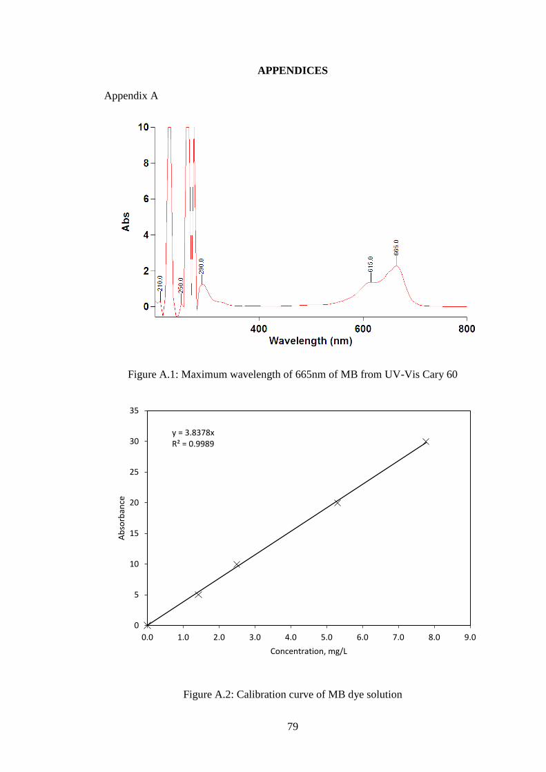
79
APPENDICES
Appendix A
Figure A.1: Maximum wavelength of 665nm of MB from UV-Vis Cary 60
Figure A.2: Calibration curve of MB dye solution
y = 3.8378xR² = 0.9989
0
5
10
15
20
25
30
35
0.0 1.0 2.0 3.0 4.0 5.0 6.0 7.0 8.0 9.0
Ab
sorb
ance
Concentration, mg/L
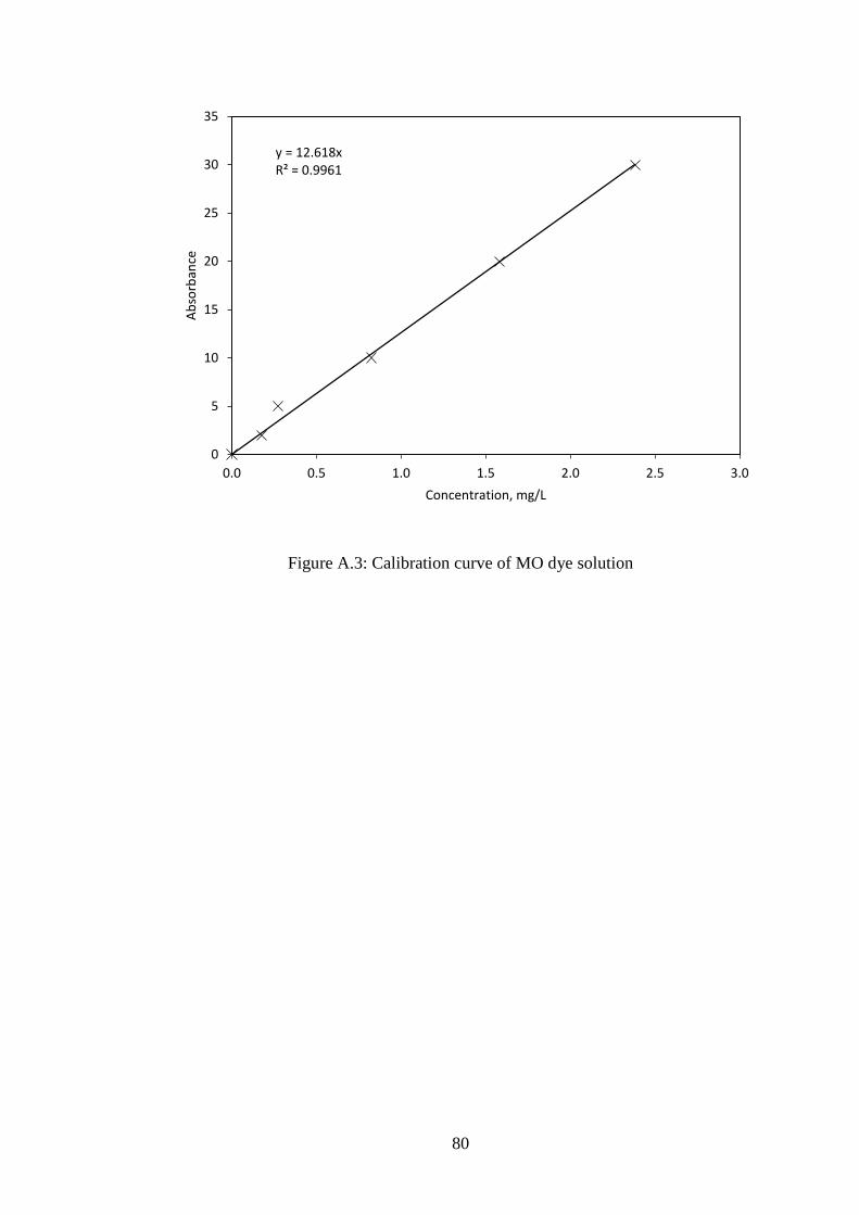
80
Figure A.3: Calibration curve of MO dye solution
y = 12.618xR² = 0.9961
0
5
10
15
20
25
30
35
0.0 0.5 1.0 1.5 2.0 2.5 3.0
Ab
sorb
ance
Concentration, mg/L

81
Appendix B
Table B.1: Data of dye removal of silica-PDDA-iron oxide nanocomposite
MO=20 ppm Co (ppm)= 16.87197 MB=20 ppm Co (ppm)= 16.45092
time abs C (ppm) % time abs C (ppm) %
abs 1 abs 2 abs 3 abs av abs 1 abs 2 abs 3 abs av
0 1.57 1.5744 1.5749 1.5731 16.871969 0 0 0.5044 0.5044 0.5041 0.5043 16.450921 0
15 0.2376 0.2376 0.2377 0.237633 8.9953722 46.68452 15 0.0151 0.0151 0.0151 0.0151 3.4770468 78.86412
30 0.2076 0.2076 0.2075 0.207567 7.8572286 53.43028 30 0.0122 0.0122 0.0121 0.012167 2.801594 82.96999
60 0.2075 0.2075 0.2077 0.207567 7.8572286 53.43028 60 0.0101 0.01 0.01 0.010033 2.3103556 85.95607
180 0.2047 0.2046 0.2046 0.204633 7.7461902 54.08841 180 0.008 0.0081 0.0081 0.008067 1.8574952 88.70887
360 0.1883 0.1882 0.1882 0.188233 7.1253846 57.76791 360 0.0071 0.007 0.0072 0.0071 1.6349028 90.06194

82
Table B.2: Data of dye removal of silica-PDDA-PSS-PDDA-iron oxide nanocomposite
MO=20 ppm Co (ppm)= 16.53233 MB=20 ppm Co (ppm)= 16.72168
time abs C (ppm) % time abs C (ppm) %
abs 1 abs 2 abs 3 abs av abs 1 abs 2 abs 3 abs av
0 1.5417 1.5415 1.5411 1.541433 16.53233493 0 0 0.5128 0.5125 0.5125 0.5126 16.72167838 0
15 0.22 0.221 0.222 0.221 8.365734 49.39775 15 0.0245 0.0246 0.0245 0.024533 5.6492416 66.21606
30 0.2154 0.2154 0.2154 0.2154 8.1537516 50.67998 30 0.0222 0.0222 0.0222 0.0222 5.1119496 69.42921
60 0.21 0.21 0.2099 0.209967 7.9480782 51.92404 60 0.0197 0.0197 0.0197 0.0197 4.5362796 72.87186
180 0.203 0.202 0.202 0.202333 7.659126 53.67184 180 0.0121 0.0121 0.0122 0.012133 2.7939184 83.29164
360 0.1919 0.192 0.1921 0.192 7.267968 56.03786 360 0.0083 0.0083 0.0083 0.0083 1.9112244 88.57038
Table B.3: Data of dye removal of silica-PEI-iron oxide nanocomposite
MO=20 ppm Co (ppm)= 16.87197 MB=20 ppm Co (ppm)= 16.45092
time abs C (ppm) % time abs C (ppm) %
abs 1 abs 2 abs 3 abs av abs 1 abs 2 abs 3 abs av
0 1.57 1.5744 1.5749 1.5731 16.87196943 0 0 0.5044 0.5044 0.5041 0.5043 16.45092159 0
15 0.208 0.209 0.208 0.208333 7.88625 53.25827 15 0.025 0.0249 0.0249 0.024933 2.8706744 82.55007
30 0.203 0.203 0.202 0.202667 7.671744 54.52965 30 0.02 0.019 0.021 0.02 2.30268 86.00273
60 0.1981 0.198 0.1981 0.198067 7.4976156 55.5617 60 0.015 0.0151 0.015 0.015033 1.7308478 89.47872
180 0.188 0.187 0.189 0.188 7.116552 57.82026 180 0.0115 0.0116 0.0117 0.0116 1.3355544 91.88158
360 0.1781 0.1782 0.178 0.1781 6.7417974 60.04143 360 0.0106 0.0105 0.0106 0.010567 1.2165826 92.60478