Embed Size (px)
Citation preview

GRUNDFOS DATA BOOKLET
Fire NKFGrundfos fire systems
Fire pump sets with electrically and diesel-powered pumpsaccording to DBI 251/CEA4001

2
Contents
Performance rangeElectrically powered pumps 3Diesel-powered pumps 4
Product descriptionIntroduction 5DBI 251/CEA 4001 standard 5Fire NKF pumps 5Controller 5Electric motor 5Diesel engine 5Other system components 6Compressor 6Scope of delivery 6Commissioning 6Identification 7Fire pump set 7Bare shaft pump 7Pump characteristics 8Duty range 8Power rating 8
Curve chartsHow to read the curve charts 9
Performance curvesNKF 32-200 (2-pole/diesel engine 2950 rpm) 10NKF 40-250 (2-pole/diesel engine 2950 rpm) 11NKF 50-200 (2-pole/diesel engine 2950 rpm) 12NKF 50-250 (2-pole/diesel engine 2950 rpm) 13NKF 65-200 (2-pole/diesel engine 2950 rpm) 14NKF 80-200 (2-pole/diesel engine 2950 rpm) 15NKF 80-250 (2-pole/diesel engine 2950 rpm) 16NKF 100-200 (2-pole/diesel engine 2950 rpm) 17NKF 125-250 (2-pole/diesel engine 2950 rpm) 18NKF 150-400 (4-pole/diesel engine 1480 rpm) 19NKF 150-400 (diesel engine 1600 rpm) 20NKF 150-400 (diesel engine 1700 rpm) 21NKF 150-400 (diesel engine 1800 rpm) 22NKF 150-500 (4-pole/diesel engine 1480 rpm) 23NKF 150-500 (diesel engine 1600 rpm) 24NKF 150-500 (diesel engine 1700 rpm) 25NKF 150-500 (diesel engine 1800 rpm) 26

Fire NKFPerformance range
Electrically powered pumps2- and 4-pole
TM04
912
2 35
10
10
01
50
20
03
00
40
05
00
60
08
00
10
00
15
00
20
00
30
00
40
00
50
00
60
00
80
00
10
00
01
50
00
Q [
l/m
in]
10
12
20
30
40
50
60
70
80
90
10
0
12
0
[m]
H
NKF
2 p
ole
/ 4
po
le
50
Hz
150-500
150-400
125-250
100-200
80-250
80-200
65- 200
65-16050-250
50-200
32-200
40-250
3

4
Performance range Fire NKF
Diesel-powered pumps
TM04
912
3 35
10
100
150
200
300
400
500
600
800
1000
1500
2000
3000
4000
5000
6000
8000
1000
015
000
Q [l
/min
]
10122030405060708090100
120
[m]
H
NKF
DIE
SEL
150-
500
125-
250
150-
400
150-
400
150-
400
150-
500
150-
400
100-
200
80-2
50
80-2
00
65-2
00
50-2
50
50-2
0032
-200
40-2
50
1600
min-1
1700
min-1
1800
min-1
1800
min-1
2950
min-1
2950
min-1
2950
min-1
2950
min-1
2950
min-1
2950
min-1
2950
min-1
2950
min-1
1480
min-1
1480
min-1
2950
min-1
Fire NKFProduct description
IntroductionGrundfos Fire NKF fire pump sets are typically used in firefighting applications for supplying water to fire hose reels, fire hydrants or sprinkler systems.
This data booklet covers fire pump sets with electrically and diesel-powered NKF end-suction pumps.
DesignationsFire NKF is an NKF end-suction pump with coupling and motor or engine mounted on a common base frame.
The fire pump set can be incorporated into a firefighting system.
DBI 251/CEA 4001 standardThe products in this data booklet have been built to comply with the DBI guidelines 251/4001 for sprinkler systems (design, installation and maintenance).
Fire NKF pumpsGrundfos NKF pumps according to DBI 251/4001 are designed for the distribution of water in stationary sprinkler systems using water spray. They are operated in case of fire and during tests.
MaterialsRequirements to pump materials according to DBI 251/4001:
• Impeller and wear rings must be made of bronze.• Wet parts such as shaft, washers and nuts must be
made of stainless steel.• Cast parts must be made of cast iron.
ControllerGrundfos offers a controller in a steel plate cabinet, suitable for wall mounting or free-standing installation.
The controller complies with the standard DBI 251/CEA4001.
The controller for pumps with electric motor can be mounted on the wall or on the base frame.
The controller for diesel-powered pumps is always mounted on the base frame.
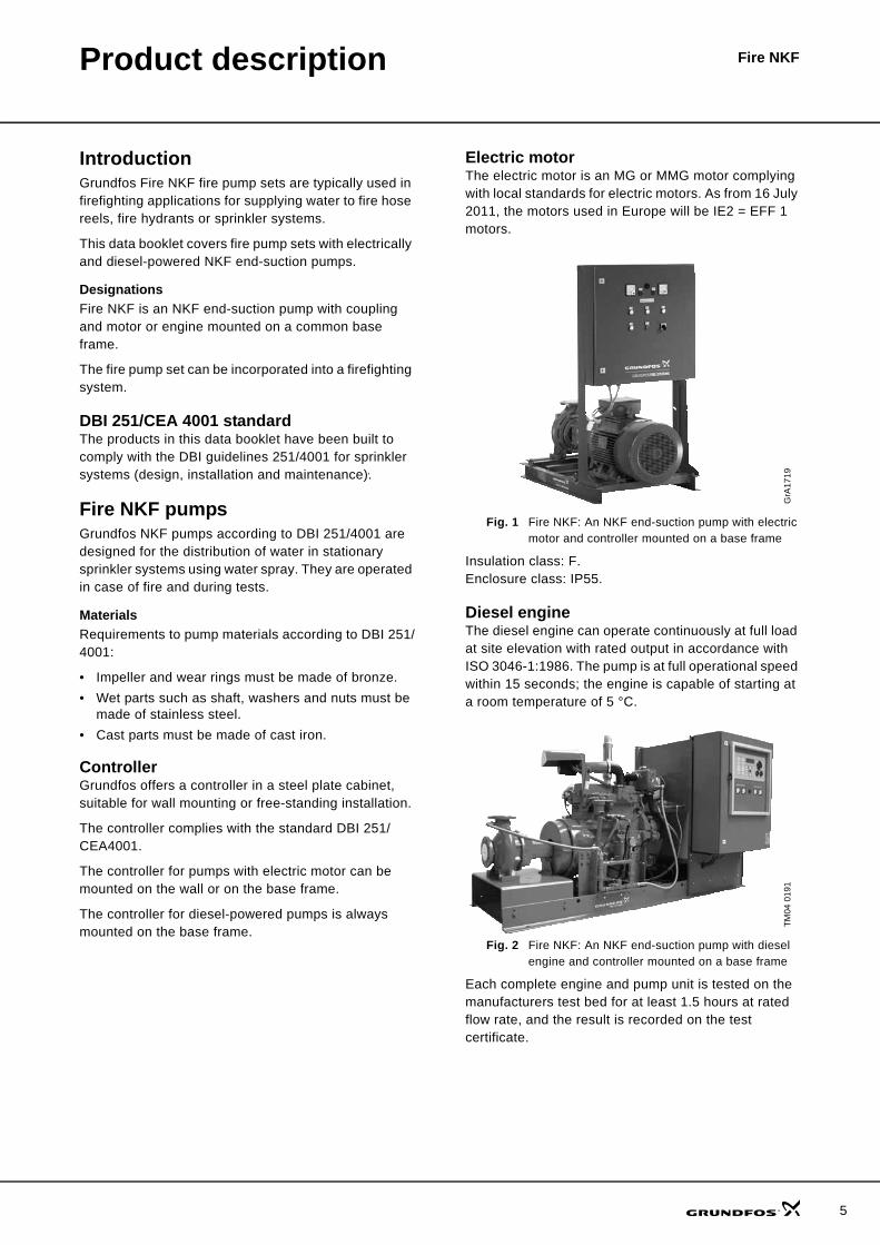
Electric motorThe electric motor is an MG or MMG motor complying with local standards for electric motors. As from 16 July 2011, the motors used in Europe will be IE2 = EFF 1 motors.
Fig. 1 Fire NKF: An NKF end-suction pump with electric motor and controller mounted on a base frame
Insulation class: F.Enclosure class: IP55.
Diesel engineThe diesel engine can operate continuously at full load at site elevation with rated output in accordance with ISO 3046-1:1986. The pump is at full operational speed within 15 seconds; the engine is capable of starting at a room temperature of 5 °C.
Fig. 2 Fire NKF: An NKF end-suction pump with diesel engine and controller mounted on a base frame
Each complete engine and pump unit is tested on the manufacturers test bed for at least 1.5 hours at rated flow rate, and the result is recorded on the test certificate.
GrA
1719
TM04
019
1
5

6
Product description Fire NKF
Other system componentsJockey pumpsGrundfos CR pumps are used as jockey pumps, maintaining the water level in the pressure tank. Under normal conditions, the jockey pump is activated by the low-level switch in the pressure tank as a result of small leakages in the pipe systems filled with water. The jockey pump operates until it is deactivated by the high-level switch. The jockey pump can also be activated in case one or more sprinklers are open, in order to maintain the water level in the pressure tank.
CompressorThe compressor can be set to manual or automatic operation by means of the selector switch.
During automatic operation, the compressor is controlled by an external pressure switch, for example connected to the pressure tank.
The compressor can be manually switched on and off.
Scope of deliveryA complete Fire NKF unit assembled and supplied from factory normally comprises these elements:
• a pump and motor mounted on a common base frame
• a standard coupling protected by a coupling guard• a controller according to DBI 251/CEA4001.
CommissioningThe installer should commission the complete firefighting system before handing it over to the plant manager on site. Many potential issues of the complete system must be tested before commissioning to ensure a satisfactory system performance and identify any damage during installation.
Key components should be checked according to the descriptions in the respective installation and operating instructions. In addition, DBI 251/CEA4001 stipulates that tests such as these should be carried out:
• pressure test of sprinkler circuits• values of all measuring devices (air pressure, water
level, etc.) to the system• water flow to fire pumps• test of alarm system and interface to municipal fire
department.The installer should supply the plant manager with the following documents:
• Installation certificate, stating that the firefighting system has been installed according to DBI 251/CEA4001 requirements.
• A complete set of installation and operating instructions and system drawings with specification of all components for the plant manager and the owner of the system.

Product description Fire NKF
Identification
Fire pump set
Fig. 3 Example of nameplate
Type key for fire pump set
Bare shaft pump
Fig. 4 Example of nameplate
Type key for pumpTM04
644
1 03
10
Example Fire NK F 80 -250 /270 E F X D B A BFire: Grundfos fire systemsType rangeNKPump approved for firefightingNominal diameter of discharge port80 mmPump housing size250 mmActual impeller diameter270 mmDriverD: Diesel engineE: Electric motor, 50 HzApproval of pumpG: ENApproval of fire pump setX: No approvalPipe connectionsD: DINControl panel B: For mounting on base frameW: For wall mountingX: No panelShaft sealA: BAQECouplingA: Standard (NKF)B: Spacer (NKF)
Type:part No.serial No.
Main Supply:
impeller diameter:
Made in Germany P1 0640
Fire NKF 80-250/270-E-F-X-D-B-A-B96157421123456789
6554
2145
6245
65
6554
2145
6245
65
3X400V 50Hz
270
min2940n:55 kWP2:kg346G:55IP
Q: H: 112 m150 m /h3
-1
TM04
644
2 03
10
Example NKF 65 -200 /219 AH -F -B -BAQE -GType rangeNKFNominal diameter of discharge port65 mmNominal impeller diameter200 mmActual impeller diameter219 mmCode for pump versionAH: NKF bare shaft pumpA2: NKF basic version with spacer couplingCode for pipework connectionF: DIN flangeCode for materialsB: EN-GJL-250 with bronze impellerCode for mechanical shaft seal and rubber pump partsApproval of pumpG: EN
-G
7

8
Product description Fire NKF
Pump characteristicsDBI 251/4001 focuses strongly on the instabilities. This is due to sprinkler systems consisting of long and different pipe circuits. Two instable pumps may cause vibrations or breakdown.
If the characteristic is instable, the instability must not exceed 5 %. See examples of instable (fig. 5) and stable (fig. 6) characteristics below.
Fig. 5 Instable pump characteristics
Fig. 6 Stable pump characteristics
Duty rangeThe maximum permissible flow rate is defined on basis of the pump NPSH curves. The flow rate must not exceed the flow rate found at 5 m NPSH.
Fig. 7 Maximum permissible flow
Power ratingTo ensure that the motor (electric motor or diesel engine) is capable of operating the pump at any time, thus ensuring water supply, DBI 251/4001 stipulates an excess capacity of motor power.
According to DBI 251/4001, the motor power is found at 16 m NPSH. The example below show a required motor size of 22 kW.
Fig. 8 Required and stipulated power
TM03
279
5 49
05TM
03 1
437
4105
0 20 40 60 80 100 120 140 160 180 Q [m³/h]
14
16
18
20
22
24
26
28
30
32
34
36
38
40
[m]H
NK 80-315
ISO 9906 Annex A
50 Hz, n = 1450 min-1
ø275
ø290
ø305
ø320
ø334
73.3 %
72.5 %
72.1 %
74.8 %
74.2 %74 %
72 %
70 %
68 %
68 %70 %
72 %
74 %
0 20 40 60 80 100 120 140 160 180 200 Q [m³/h]
4
8
12
16
20
24
28
32
36
40
44
48
52
56
60
64
68[m]H
NKF 65-200
ISO 9906 Annex A
2-pole, 50 Hz
ø170
ø185
ø195
ø215
ø219 37 kW
30 kW
22 kW
18,5 kW
15 kWTM
04 9
207
3710
TM04
649
2 05
10
0 2000 4000 6000 8000 10000 Q [l/min]
5
10
15
20
25
30
35
40
45
50
55
60
65
[m]H
0 100 200 300 400 500 600 Q [m³/h]
ø318
ø410
45 kW
110 kW
0 2000 4000 6000 8000 10000 Q [l/min]
0
20
40
60
80
100
[kW]P2
0
5
10
15
20
NPSH[m]
ø318 (Min. NPSH)
ø410 (Max. NPSH)
ø318
ø410
0 10 20 30 40 50 60 70 80 90 100 110 120 130 Q [m³/h]
0
4
8
12
16
20
24
[kW]P2
0
4
8
12
16
20
NPSH[m]
ø170
ø194
ø207
ø219
ø170 (Min. NPSH) ø219 (Max. NPSH)
P2 required

9
Fire NKFCurve charts
How to read the curve charts
TM04
803
3 27
10
0 500 1000 1500 2000 2500 3000 3500 4000 4500 5000 5500 Q [l/min]
15
20
25
30
35
40
45
50
55
60
65
70
[m]H
0 50 100 150 200 250 300 Q [m³/h]
NKF 80-200
ISO 9906 Annex A
2-pole, 50 Hz
2950/3000 rpm
DBI 251/4001
ø188
ø202
ø213
ø222
55 kW
45 kW
37 kW
30 kW
0 500 1000 1500 2000 2500 3000 3500 4000 4500 5000 5500 Q [l/min]
0
10
20
30
40
50
[kW]P2
0
5
10
15
20
NPSH[m]
ø188 (Min. NPSH) ø222 (Max. NPSH)
ø188
ø202
ø213
ø222
Pump type and frequency of motor
Impeller size
Total pump head:H = Htotal
The power curve indicates pump input power P2. P2 is found at 16 m NPSH.
The NPSH curves are according to the minimum and maximum impeller diameter.
QH curve for the individual pump
This line indicates the limit of the individual pump performance found at 5 m NPSH.

10
Performance curves
NKF 32-200 (2-pole/diesel engine 2950 rpm)
Circulation flow = 2 % of rated flow rate.
The performance curves of electrically and diesel-powered pumps are approximately similar and based on the values in table below.
TM04
802
8 27
10
0 100 200 300 400 500 600 700 800 Q [l/min]
0
5
10
15
20
25
30
35
40
45
50
55
60
65
70
75
[m]H
0 10 20 30 40 50 Q [m³/h]
NKF 32-200
ISO 9906 Annex A
2-pole, 50 Hz
DBI 251/4001
2950/3000 rpm
ø171
ø185
ø200
ø219
11 kW
4 kW
5.5 kW
7.5 kW
0 100 200 300 400 500 600 700 800 Q [l/min]
0
2
4
6
8
10
[kW]P2
0
10
20
NPSH[m]
ø219 (NPSH)ø185 (NPSH)
ø171
ø185
ø200
ø219
Impeller sizes[mm]
P2 [kW]Electric motor Diesel engine
> ∅ 206 ≤ ∅ 219 11 (2930 rpm)
19> ∅ 190 ≤ ∅ 206 7.5 (2900 rpm)
> ∅ 176 ≤ ∅ 190 5.5 (2900 rpm)
= ∅ 176 4 (2890 rpm)
NKF 32-2002-pole
diesel engine

NKF 40-2502-pole
diesel enginePerformance curves
NKF 40-250 (2-pole/diesel engine 2950 rpm)
Circulation flow = 2 % of rated flow rate.
The performance curves of electrically and diesel-powered pumps are approximately similar and based on the values in table below.
TM04
802
9 27
10
0 100 200 300 400 500 600 700 800 900 1000 1100 1200 1300 1400 Q [l/min]
0
10
20
30
40
50
60
70
80
90
100
110
[m]H
0 10 20 30 40 50 60 70 80 Q [m³/h]
NKF 40-250
ISO 9906 Annex A
2-pole, 50 Hz
DBI 251/4001
2950/3000 rpm
ø210
ø230
ø238
ø250
ø260
30 kW
15 kW
18.5 kW
22 kW
11 kW
0 100 200 300 400 500 600 700 800 900 1000 1100 1200 1300 1400 Q [l/min]
0
4
8
12
16
20
24
[kW]P2
0
10
20
NPSH[m]
ø210 (NPSH)
ø210
ø230
ø238
ø250
ø260
ø260 (NPSH)
Impeller sizes[mm]
P2 [kW]Electric motor Diesel engine
> ∅ 255 ≤ ∅ 260 30 (2960 rpm) 48
> ∅ 245 ≤ ∅ 255 22 (2950 rpm) 26
> ∅ 230 ≤ ∅ 245 18.5 (2940 rpm)
19> ∅ 211 ≤ ∅ 230 15 (2940 rpm)
= ∅ 211 11 (2930 rpm)
11

12
NKF 50-2002-pole
diesel enginePerformance curves
NKF 50-200 (2-pole/diesel engine 2950 rpm)
Circulation flow = 2 % of rated flow rate.
The performance curves of electrically and diesel-powered pumps are approximately similar and based on the values in table below.
TM04
803
1 27
10
0 200 400 600 800 1000 1200 1400 1600 1800 2000 Q [l/min]
4
8
12
16
20
24
28
32
36
40
44
48
52
56
60
64
68
[m]H
0 20 40 60 80 100 120 Q [m³/h]
NKF 50-200
ISO 9906 Annex A
2-pole, 50 Hz
DBI 251/4001
2900/3000 rpm
ø170
ø194
ø207
ø219
22 kW
18,5 kW
15 kW
11 kW
0 200 400 600 800 1000 1200 1400 1600 1800 2000 Q [l/min]
0
4
8
12
16
20
24
[kW]P2
0
4
8
12
16
20
NPSH[m]
ø170
ø194
ø207
ø219
ø170 (Min. NPSH)
ø219 (Max. NPSH)
Impeller sizes[mm]
P2 [kW]Electric motor Diesel engine
> ∅ 207 ≤ ∅ 219 22 (2950 rpm) 26
> ∅ 194 ≤ ∅ 207 18.5 (2940 rpm)
19> ∅ 170 ≤ ∅ 194 15 (2940 rpm)
= ∅ 170 11 (2930 rpm)

NKF 50-2502-pole
diesel enginePerformance curvesPerformance curves
NKF 50-250 (2-pole/diesel engine 2950 rpm)
Circulation flow = 2 % of rated flow rate.
The performance curves of electrically and diesel-powered pumps are approximately similar and based on the values in table below.
TM04
803
9 27
10
0 200 400 600 800 1000 1200 1400 1600 1800 2000 2200 Q [l/min]
0
10
20
30
40
50
60
70
80
90
100
110
[m]H
0 20 40 60 80 100 120 Q [m³/h]
NKF 50-250
ISO 9906 Annex A
2-pole, 50 Hz
DBI 251/4001
2950/3000 rpm
ø205
ø220
ø249
ø263
30 kW
37 kW
18.5 kW
22 kW
0 200 400 600 800 1000 1200 1400 1600 1800 2000 2200 Q [l/min]
0
5
10
15
20
25
30
35
[kW]P2
0
10
20
NPSH
[m]
ø205 (NPSH) ø263 (NPSH)
ø205
ø220
ø249
ø263
Impeller sizes[mm]
P2 [kW]Electric motor Diesel engine
> ∅ 249 ≤ ∅ 263 37 (2960 rpm)48
> ∅ 220 ≤ ∅ 249 30 (2960 rpm)
> ∅ 205 ≤ ∅ 220 22 (2950 rpm) 26
= ∅ 205 18.5 (2940 rpm) 19
13

14
NKF 65-2002-pole
diesel enginePerformance curves
NKF 65-200 (2-pole/diesel engine 2950 rpm)
Circulation flow = 2 % of rated flow rate.
The performance curves of electrically and diesel-powered pumps are approximately similar and based on the values in table below.
TM04
803
2 27
10
0 400 800 1200 1600 2000 2400 2800 3200 Q [l/min]
4
8
12
16
20
24
28
32
36
40
44
48
52
56
60
64
68
[m]H
0 500 1000 1500 2000 2500 3000 3500 Q [l/min]
NKF 65-200
ISO 9906 Annex A
2-pole, 50 Hz
DBI 251/4001
2950/3000 rpm
ø170
ø185
ø195
ø215
ø219 37 kW
30 kW
22 kW
18,5 kW
15 kW
0 400 800 1200 1600 2000 2400 2800 3200 Q [l/min]
0
5
10
15
20
25
30
[kW]P2
0
4
8
12
16
20
NPSH[m]
ø170 (Min. NPSH)
ø170
ø185
ø195
ø215ø219
ø219 (Max. NPSH)
Impeller sizes[mm]
P2 [kW]Electric motor Diesel engine
> ∅ 215 ≤ ∅ 219 37 (2960 rpm)48
> ∅ 195 ≤ ∅ 215 30 (2960 rpm)
> ∅ 186 ≤ ∅ 195 22 (2950 rpm) 26
> ∅ 170 ≤ ∅ 186 18.5 (2940 rpm)19
= ∅ 170 15 (2940 rpm)

NKF 80-2002-pole
diesel enginePerformance curves
NKF 80-200 (2-pole/diesel engine 2950 rpm)
Circulation flow = 2 % of rated flow rate.
The performance curves of electrically and diesel-powered pumps are approximately similar and based on the values in table below.
TM04
803
3 27
10
0 500 1000 1500 2000 2500 3000 3500 4000 4500 5000 5500 Q [l/min]
15
20
25
30
35
40
45
50
55
60
65
70
[m]H
0 50 100 150 200 250 300 Q [m³/h]
NKF 80-200
ISO 9906 Annex A
2-pole, 50 Hz
2950/3000 rpm
DBI 251/4001
ø188
ø202
ø213
ø222
55 kW
45 kW
37 kW
30 kW
0 500 1000 1500 2000 2500 3000 3500 4000 4500 5000 5500 Q [l/min]
0
10
20
30
40
50
[kW]P2
0
5
10
15
20
NPSH[m]
ø188 (Min. NPSH) ø222 (Max. NPSH)
ø188
ø202
ø213
ø222
Impeller sizes[mm]
P2 [kW]Electric motor Diesel engine
> ∅ 213 ≤ ∅ 222 55 (2960 rpm) 64
> ∅ 202 ≤ ∅ 213 45 (2980 rpm)
48> ∅ 188 ≤ ∅ 202 37 (2960 rpm)
= ∅ 188 30 (2960 rpm)
15

16
NKF 80-2502-pole
diesel enginePerformance curves
NKF 80-250 (2-pole/diesel engine 2950 rpm)
Circulation flow = 2 % of rated flow rate.
The performance curves of electrically and diesel-powered pumps are approximately similar and based on the values in table below.
TM04
803
4 27
10
0 500 1000 1500 2000 2500 3000 3500 4000 4500 5000 5500 6000 Q [l/min]
10
20
30
40
50
60
70
80
90
100
110
[m]H
0 50 100 150 200 250 300 350 Q [m³/h]
NKF 80-250
ISO 9906 Annex A
2-pole, 50 Hz
2950/3000 rpm
DBI 251/4001
ø216
ø233
ø255
ø270
90 kW
75 kW
55 kW
45 kW
0 500 1000 1500 2000 2500 3000 3500 4000 4500 5000 5500 6000 Q [l/min]
0
20
40
60
80
100
[kW]P2
0
5
10
15
20
NPSH[m]
ø216 (Min. NPSH)
ø270 (Max. NPSH)
ø216
ø233
ø255
ø270
Impeller sizes[mm]
P2 [kW]Electric motor Diesel engine
> ∅ 255 ≤ ∅ 270 90 (2980 rpm)96
> ∅ 233 ≤ ∅ 255 75 (2970 rpm)
> ∅ 216 ≤ ∅ 233 55 (2960 rpm) 64
= ∅ 216 45 (2980 rpm) 48

NKF 100-2002-pole
diesel enginePerformance curves
NKF 100-200 (2-pole/diesel engine 2950 rpm)
Circulation flow = 2 % of rated flow rate.
The performance curves of electrically and diesel-powered pumps are approximately similar and based on the values in table below.
TM04
803
5 27
10
0 500 1000 1500 2000 2500 3000 3500 4000 4500 5000 5500 6000 6500 7000 Q [l/min]
0
5
10
15
20
25
30
35
40
45
50
55
60
65
70
[m]H
0 50 100 150 200 250 300 350 400 Q [m³/h]
NKF 100-200
ISO 9906 Annex A
2-pole, 50 Hz
2950/3000 rpm
DBI 251/4001ø209
ø215
ø219
75 kW
45 kW
55 kW
0 500 1000 1500 2000 2500 3000 3500 4000 4500 5000 5500 6000 6500 7000 Q [l/min]
0
10
20
30
40
50
60
70
[kW]P2
0
4
8
12
16
NPSH[m]
ø209
ø215
ø219
ø209 (NPSH) ø219 (NPSH)
NBF, NKF 100-200Impeller sizes
P2 [kW]Electric motor Diesel engine
> ∅ 215 ≤ ∅ 219 75 (2970 rpm)64
> ∅ 209 ≤ ∅ 215 55 (2960 rpm)
= ∅ 209 45 (2980 rpm) 48
17

18
NKF 125-2502-pole
diesel enginePerformance curves
NKF 125-250 (2-pole/diesel engine 2950 rpm)
Circulation flow = 2 % of rated flow rate.
The full lines show the performance curves of electrically powered pumps. The dotted lines show the performance curves of diesel-powered pumps.
TM04
804
0 27
10
0 1000 2000 3000 4000 5000 6000 7000 8000 9000 10000 11000 Q [l/min]
0
10
20
30
40
50
60
70
80
90
100
110
[m]H
0 100 200 300 400 500 600 Q [m³/h]
NKF 125-250
ISO 9906 Annex A
2-pole, 50 Hz
DBI 251/4001
2950/3000 rpm
ø226
ø255
ø242
ø250
ø262
ø265
ø226
ø237
ø245
ø255
ø269200 kW
90 kW
110 kW
132 kW
160 kW
0 1000 2000 3000 4000 5000 6000 7000 8000 9000 10000 11000 Q [l/min]
0
20
40
60
80
100
120
140
160
180
[kW]P2
0
4
8
12
16
NPSH
[m]ø226
ø237
ø245
ø255
ø269
ø226 (NPSH)
ø269 (NPSH)
NBF, NKF 125-250Impeller sizes
P2 [kW] NBF, NKF 125-250Impeller sizes
P2 [kW]Electric motor Diesel engine
> ∅ 255 ≤ ∅ 269 200 (2990 rpm) > ∅ 262 ≤ ∅ 265 184
> ∅ 245 ≤ ∅ 255 160 (2990 rpm) > ∅ 250 ≤ ∅ 262 178
> ∅ 237 ≤ ∅ 245 132 (2990 rpm) > ∅ 242 ≤ ∅ 250 147
≤ ∅ 237 110 (2990 rpm) ≤ ∅ 242 119

Performance curves
NKF 150-400 (4-pole/diesel engine 1480 rpm)
Circulation flow = 2 % of rated flow rate.
The performance curves of electrically and diesel-powered pumps are approximately similar and based on the values in table below.
TM04
803
7 27
10
0 1000 2000 3000 4000 5000 6000 7000 8000 9000 10000 11000 12000 Q [l/min]
0
5
10
15
20
25
30
35
40
45
50
55
60
65
[m]H
0 100 200 300 400 500 600 700 Q [m³/h]
NKF 150-400
ISO 9906 Annex A
4-pole, 50 Hz
1480 rpm
DBI 251/4001
ø318
ø335
ø368
ø389
ø410
45 kW
55 kW
75 kW
90 kW
110 kW
0 1000 2000 3000 4000 5000 6000 7000 8000 9000 10000 11000 12000 Q [l/min]
0
20
40
60
80
100
120
[kW]P2
0
5
10
15
20
NPSH[m]
ø318 (Min. NPSH)ø410 (Max. NPSH)
ø318
ø335
ø368
ø389
ø410
Impeller sizes[mm]
P2 [kW]Electric motor Diesel engine
> ∅ 389 ≤ ∅ 410 110 (1490)113
> ∅ 368 ≤ ∅ 389 90 (1480)
> ∅ 335 ≤ ∅ 368 75 (1480) 77
> ∅ 318 ≤ ∅ 335 55 (1480)65
= ∅ 318 45 (1480)
NKF 150-4004-pole
diesel engine
19

20
NKF 150-400diesel enginePerformance curves
NKF 150-400 (diesel engine 1600 rpm)
Circulation flow = 2 % of rated flow rate.
TM04
911
5 35
10
0 2000 4000 6000 8000 10000 12000 14000Q [l/min]
0
5
10
15
20
25
30
35
40
45
50
55
60
65
70
75
[m]H
0 200 400 600 800 Q [m³/h]
NKF 150-400
ISO 9906 Annex A
1600 rpm
DBI 251/4001
ø318
ø335
ø368
ø389
ø410
0 2000 4000 6000 8000 10000 12000 14000Q [l/min]
0
20
40
60
80
100
120
140
[kW]P2
0
5
10
15
20
NPSH[m]
ø318 (Min. NPSH) ø410 (Max. NPSH)
ø318
ø335
ø368
ø389
ø410
Impeller size[mm]
P2 [kW]Diesel engine
> ∅ 389 ≤ ∅ 410 152
> ∅ 368 ≤ ∅ 389 129
> ∅ 335 ≤ ∅ 368 93
≤ ∅ 335 76

NKF 150-400diesel enginePerformance curves
NKF 150-400 (diesel engine 1700 rpm)
Circulation flow = 2 % of rated flow rate.
TM04
911
6 35
10
0 2000 4000 6000 8000 10000 12000 14000 Q [l/min]
0
5
10
15
20
25
30
35
40
45
50
55
60
65
70
75
80
85
[m]H
0 200 400 600 800 Q [m³/h]
NKF 150-400
ISO 9906 Annex A
1700 rpm
DBI 251/4001
ø318
ø335
ø368
ø389
ø410
0 2000 4000 6000 8000 10000 12000 14000 Q [l/min]
0
20
40
60
80
100
120
140
160
[kW]P2
0
5
10
15
20
NPSH[m]
ø318 (Min. NPSH) ø410 (Max. NPSH)
ø318
ø335
ø368
ø389
ø410
Impeller size[mm]
P2 [kW]Diesel engine
> ∅ 389 ≤ ∅ 410 159
> ∅ 368 ≤ ∅ 389 141
> ∅ 335 ≤ ∅ 368 107
≤ ∅ 335 85
21

22
NKF 150-400diesel enginePerformance curves
NKF 150-400 (diesel engine 1800 rpm)
Circulation flow = 2 % of rated flow rate.
TM04
911
7 35
10
0 2000 4000 6000 8000 10000 12000 14000 Q [l/min]
0
5
10
15
20
25
30
35
40
45
50
55
60
65
70
75
80
85
90
95
[m]H
0 200 400 600 800 Q [m³/h]
NKF 150-400
ISO 9906 Annex A
1800 rpm
DBI 251/4001
ø318
ø335
ø368
ø389
ø410
0 2000 4000 6000 8000 10000 12000 14000 Q [l/min]
0
20
40
60
80
100
120
140
160
180
200
[kW]P2
0
5
10
15
20
NPSH
[m]
ø318 (Min. NPSH) ø410 (Max. NPSH)
ø318
ø335
ø368
ø389
ø410
Impeller size[mm]
P2 [kW]Diesel engine
> ∅ 389 ≤ ∅ 410 218
> ∅ 335 ≤ ∅ 389 152
≤ ∅ 335 92

NKF 150-5004-pole
diesel enginePerformance curves
NKF 150-500 (4-pole/diesel engine 1480 rpm)
Circulation flow = 2 % of rated flow rate.
The performance curves of electrically and diesel-powered pumps are approximately similar and based on the values in table below.
TM04
803
8 27
10
0 1000 2000 3000 4000 5000 6000 7000 8000 9000 10000 11000 12000 13000 Q [l/min]
0
10
20
30
40
50
60
70
80
90
100
110
120
[m]H
0 100 200 300 400 500 600 700 800Q [m³/h]
NKF 150-500
ISO 9906 Annex A
4-pole, 50 Hz
1480 rpm
DBI 251/4001
/415
/441
/476
/518
/538
250 kW
200 kW
160 kW
132 kW
110 kW
0 1000 2000 3000 4000 5000 6000 7000 8000 9000 10000 11000 12000 13000 Q [l/min]
0
40
80
120
160
200
240
[kW]P2
0
10
20
NPSH[m]
/415 (Min. NPSH) /538 (Max. NPSH)
/415
/441
/476
/518
/538
Impeller sizes[mm]
P2 [kW]Electric motor Diesel engine
> ∅ 518 ≤ ∅ 538 250 (1490) 113
> ∅ 476 ≤ ∅ 518 200 (1480) 197
> ∅ 441 ≤ ∅ 476 160 (1480) 180
> ∅ 415 ≤ ∅ 441 132 (1480) 143
= ∅ 415 110 (1480) 113
23

24
NKF 150-500diesel enginePerformance curves
NKF 150-500 (diesel engine 1600 rpm)
Circulation flow = 2 % of rated flow rate.
TM04
911
8 35
10
0 1000 2000 3000 4000 5000 6000 7000 8000 9000 10000 11000 Q [l/min]
0
10
20
30
40
50
60
70
80
90
[m]H
0 100 200 300 400 500 600 Q [m³/h]
NKF 150-500
ISO 9906 Annex A
1600 rpm
DBI 251/4001
/415
/441
0 1000 2000 3000 4000 5000 6000 7000 8000 9000 10000 11000 Q [l/min]
0
40
80
120
160
[kW]P2
0
10
20
NPSH
[m]
/415
/415 (Min. NPSH)
/441
/441 (Max. NPSH)
Impeller size[mm]
P2 [kW]Diesel engine
> ∅ 415 ≤ ∅ 441 196
≤ ∅ 415 152

NKF 150-500diesel enginePerformance curves
NKF 150-500 (diesel engine 1700 rpm)
Circulation flow = 2 % of rated flow rate.
TM04
911
9 35
10
0 2000 4000 6000 8000 10000 12000 14000Q [l/min]
0
10
20
30
40
50
60
70
80
90
100
[m]H
0 200 400 600 800 Q [m³/h]
NKF 150-500
ISO 9906 Annex A
1700 rpm
DBI 251/4001
/415
/441
0 2000 4000 6000 8000 10000 12000 14000Q [l/min]
0
40
80
120
160
200
[kW]P2
0
10
20
NPSH[m]
/415 (Min. NPSH) /441 (Max. NPSH)
/415
/441
Impeller size[mm]
P2 [kW]Diesel engine
≤ ∅ 441 209
25

26
NKF 150-500diesel enginePerformance curves
NKF 150-500 (diesel engine 1800 rpm)
Circulation flow = 2 % of rated flow rate.
TM04
912
0 35
10
0 2000 4000 6000 8000 10000 12000 14000Q [l/min]
0
10
20
30
40
50
60
70
80
90
100
110
120
[m]H
0 200 400 600 800 Q [m³/h]
NKF 150-500
ISO 9906 Annex A
1800 rpm
DBI 251/4001
/415
/441
0 2000 4000 6000 8000 1e+004 1e+004 Q [l/min]
0
40
80
120
160
200
240
[kW]P2
0
10
20
NPSH[m]
/415 (Min. NPSH)
/441 (Min. NPSH)
/415
/441
Impeller size[mm]
P2 [kW]Diesel engine
> ∅ 415 ≤ ∅ 441 238
≤ ∅ 415 218

27

www.grundfos.com
Being responsible is our foundationThinking ahead makes it possible
Innovation is the essence
GRUNDFOS A/S . DK-8850 Bjerringbro . DenmarkTelephone: +45 87 50 14 00
The name Grundfos, the Grundfos logo, and the payoff Be–Think–Innovate are registrated trademarks owned by Grundfos Management A/S or Grundfos A/S, Denmark. All rights reserved worldwide.
97769352 1010 GBECM: 1066243


![Grundfos MLD.15.3.4 pump : MLD.15.3.4 3x400V (97901107)Printed from Grundfos Product Centre [2018.02.043] Position Qty. Description 1 MLD.15.3.4 Note! Product picture may differ from](https://img.dokumen.tips/doc/110x75/60cf74ea4c52565c4075227f/grundfos-mld1534-pump-mld1534-3x400v-97901107-printed-from-grundfos-product.jpg)

![Grundfos MDG.40.3.2 pump : MDG.40.3.2 3x400V (97901146) · Printed from Grundfos Product Centre [2018.02.043] 97901146 MDG.40.3.2 50 Hz Note! All units are in [mm] unless others are](https://img.dokumen.tips/doc/110x75/5ea81ac3c935ab6e537d7575/grundfos-mdg4032-pump-mdg4032-3x400v-97901146-printed-from-grundfos-product.jpg)