Embed Size (px)
Citation preview

GRUNDFOS DATA BOOKLET
Fire NKFGrundfos fire systems
Fire systems with electrically powered (50 Hz) pumpsapproved by VdS

2
Contents
VdS standardIntroduction to VdS 3VdS standards 3Standards approval process 3Certificate 4Overview of fire system 8Fire pumps 9Duty range 9Motor power rating 11Specifications 11Electrical motors 12Jockey pumps 12Controller 12Commissioning 12
Product descriptionIntroduction 13NKF pump features 13
Performance rangeNKF, 2- and 4-pole 14
Product rangeProduct numbers 15VdS approval numbers 15
IdentificationType key 16Shaft seals 16Nameplate 16
ConstructionSectional drawing, NKF, model B 17Material specification 17Sectional drawing, NKF, model A 18Material specification 18Mechanical construction 19Surface treatment 20Test pressure 20Motor 20
Operating conditionsPump unit location 21Ambient temperature and altitude 21Duty range of shaft seal 21Inlet pressure 21Maximum inlet pressure 21Minimum inlet pressure 21
Installation and operationPiping 22Alignment 22
Motor dataMotor range, 2-pole 23Motor range, 4-pole 23
Bare shaft pumpsNKF, model B 24NKF, model A 25Flange dimensions 26
Curve chartsHow to read the curve charts 27Curve conditions 28Selection of pumps 28Calculation of total head 28Performance tests 28VdS certificate 28
Performance curvesNKF 50-200, 2-pole 29NKF 65-200, 2-pole 30NKF 80-200, 2-pole 31NKF 80-250, 2-pole 32NKF 150-400, 4-pole 33NKF 150-500, 4-pole 34NKF 200-500, 4-pole 35
Technical dataInstallation dimensions 36
ControllerGeneral description 48Controller versions 48Identification 48Construction 49Control panel 49Potential-free signalling contact 50Cables 50Optional equipment 50Controller components 50Operating conditions 51Installation 51General information 51Electrical connection 51Motor connection 51Operation 52Fire pump 52Jockey pump 52Compressor 52Pressure-maintaining pump 52Level indication 52Motor valve 52Technical data 52Optional equipment 52Product numbers 53Options 53Cabinet dimensions 53

Fire NKFVdS standard
Introduction to VdSVdS Schadenverhütung GmbH is an independent, international, accredited and notified testing and certification institution for fire prevention and safety technology as well as for physical and electronic protection against intrusion. ("Schadenverhütung" is the German word for "loss prevention".)
Accredited according to the EN 45000 series of European standards, VdS Schadenverhütung is a member of the European Fire and Security Group (EFSG). VdS experts are represented in all relevant German and international committees.
The concept behind VdS recognition is to ensure tested and certified quality in the products and services offered in the safety and security markets. This is equally advantageous for user and supplier.
For further information on VdS, see www.vds.de.
VdS standardsThe products in this data booklet have been built to comply with VdS standards on water-based fire fighting systems, described in the following documents:
• VDS CEA 4001:2005-09 (02): Planning and installation.
• VDS 2100: Guidelines for water-based fire fighting systems.
• VDS 2344: Procedures for testing and approval of equipment, components and systems used in fire protection and security control.
Standards approval processGrundfos is to test the pumps and fill in the application forms for each individual pump size. The following documentation should to submitted to the VdS:
• complete drawings with list of parts and materials of the major components
• a statement regarding quality and production (ISO 9001 + Annex A & D)
• a complete data sheet with technical information• complete installation and operating instructions.If the application forms are accepted, VdS will attend the final test at the Grundfos premises. If the evaluation of the test results is positive, VdS will issue a certificate on the approval of the pump.
3

4
VdS standard Fire NKF
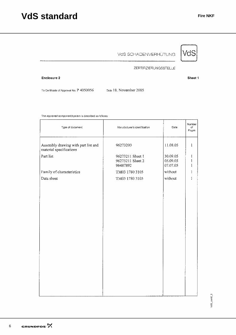
CertificateExample of VdS certificate of approval
VdS
_cer
tif_1
Update
d cert
ificate
is pe
nding
.

VdS standard Fire NKF
VdS_
certi
f_2
5
6
VdS standard Fire NKF
VdS
_cer
tif_3

VdS standard Fire NKF
VdS
_cer
tif_4
7

8
VdS standard Fire NKF
Overview of fire system
Fig. 1 Overview of fire system
Fire system designA fire system typically consists of three pumps: one pressure pump (jockey pump) and two fire pumps, one duty and the other acting as standby. Each of the fire pumps is capable of achieving the required performance.
Systems with only one fire pump or more than two fire pumps are, however, also seen.
FunctionThe duty and standby pumps are not powered by the same source. Either both pumps are electrically powered, supplied by two separate sources, or one pump is electrically powered and the other diesel-powered. This ensures that if one pump fails, for example due to fire damage, the other will operate.
The pumps are pressure-controlled by pressure sensors.
The pressure in the system is normally maintained by the pressure tank.
If the system pressure drops, the water level and air pressure in the tank will decrease.
The jockey pump starts to fill the tank, and the compressor to boost the pressure. If the jockey pump and the compressor succeed in boosting the water level and the pressure to a set value, both will stop. If a sprinkler has been activated and the water level and the pressure keeps falling, the duty pump will start.
A further decrease in the pressure means that the duty pump is not running, and the standby pump will start.
The same principle applies to the dry sprinkler system in which an air compressor maintains pressure from the alarm valve and through the sprinkler system.
Although individually designed for the specific installation, each fire system must comply with VdS standards.
Important!Requirements as to design, sizing and testing of fire protection systems vary from one country to another.
TM03
295
9 50
05
9
6
3
14
13
124
10
11
8
5a
5
2
7
1a
7
1
)(
A
A
x
x x x
x x
Pos. Description Pos. Description Pos. Description1 Fire pump, electrically powered 5a Overflow 11 Overpressure backflow string
1a Fire pump, diesel powered 6 Pressure tank 12 Fire hydrant2 Jockey pump 7 Fire pump priming tank 13 Wet sprinkler system3 Compressor 8 Water supply 14 Dry sprinkler system4 Controller 9 Alarm valve5 Intermediate water tank 10 Test-running string/bleed line

VdS standard Fire NKF
Fire pumpsGrundfos end-suction pumps approved by VdS are designed for the distribution of water in stationary sprinkler systems using either foam or water spray. They are operated in case of fire and during tests.
MaterialsRequirements of materials for VdS-approved pumps:
• impeller and wear rings made of bronze• wet parts such as shaft, washers and nuts made of
stainless steel• castings made of EN-GJL-250.VdS requirements for EN-GJL-250 do not allow heads (H) above 110 metres and flows (Q) above 600 m3/h.
Pump characteristicVdS focuses strongly on the instabilities, due to sprinkler systems consisting of long and different pipe circuits. Two instable pumps may cause vibrations or breakdown.
If the pump characteristic is instable, it is not allowed to exceed 5 %. See examples of instable (fig. 2) and stable (fig. 3) pump characteristics below.
Fig. 2 Instable pump characteristics
Fig. 3 Stable pump characteristics
Duty rangeVdS operates with a concept known as Qzul (zulässig = permissible), see fig 4. The duty point of the pump must not be to the right of this limit.
Qzul is defined on the basis of the pump NPSH curves. The following calculation must be made for the largest and smallest pump impeller diameter.
TM03
279
5 49
05
0 20 40 60 80 100 120 140 160 180 Q [m³/h]
14
16
18
20
22
24
26
28
30
32
34
36
38
40
[m]H
NK 80-315
ISO 9906 Annex A
50 Hz, n = 1450 min-1
ø275
ø290
ø305
ø320
ø334
73.3 %
72.5 %
72.1 %
74.8 %
74.2 %74 %
72 %
70 %
68 %
68 %70 %
72 %
74 %
TM03
279
6 49
05
Find the flow at 4.5 m and 5.5 m NPSH
Multiply the value Q4.5 m NPSH by 1.2
Does the result exceed the value of Q5.5 m NPSH?
YesQzul = Q5.5 m NPSH / 1.2
No
Qzul = Q4.5 m NPSH
0 100 200 300 400 500 600 700 800 Q [m³/h]
0
10
20
30
40
50
60
70
80
90
100
110
[m]H
0 2000 4000 6000 8000 10000 12000 14000 Q [l/min]
NKF 200-500
ISO 9906 Annex A
50 Hz
ø446
ø471
ø512
ø530
132 kW
160 kW
200 kW
250 kW
9

10
VdS standard Fire NKF
Fig. 4 Indication of calculation of Qzul
TM03
279
4 49
05
0 10 20 30 40 50 60 70 80 90 100 110 120 130 Q [m³/h]
4
8
12
16
20
24
28
32
36
40
44
48
52
56
60
64
68[m]H
0 500 1000 1500 2000 Q [l/min]
NKF 50-200
ISO 9906 Annex A
50 Hz
ø170
ø194
ø207
ø219
22 kW
18,5 kW
15 kW
11 kW
0 10 20 30 40 50 60 70 80 90 100 110 120 130 Q [m³/h]
0
4
8
12
16
20
24
[kW]P2
0
4
8
12
16
20
NPSH[m]
ø170
ø194
ø207
ø219
ø170 (Min. NPSH)
ø219 (Max. NPSH)
Qzul
5.54.5
93 110 119
9978

VdS standard Fire NKF
ExampleThe following example shows how Qzul has been shown for the pump characteristics in fig. 4.
Qzul for ∅219 impeller:
The maximum permissible flow of an NKF 50-200 pump with ∅219 impeller is 99 m3/h.
Qzul for ∅170 impeller:
The maximum permissible flow of an NKF 50-200 pump with ∅170 impeller is 78 m3/h.
On the basis of Qzul ∅219 and Qzul ∅170, the limit Qzul can be drawn and the duty range of the impellers in between can be read.
Motor power ratingTo ensure that the motor is capable of operating the pump at any time, so that it can deliver water, VdS requires an excess capacity of motor power.
According to VdS, the motor power is found at 16 m NPSH. The example below is based on Qzul = 99 m3/h as previously calculated.
Fig. 5 Necessary and required power
SpecificationsEach curve chart is followed by a specification of technical data. See table below.
VdS Approval NoEach pump has its own VdS approval number.
D2 normal
D2 indicates the largest impeller diameter of the specific pump.
D2 turned downD2 turned down indicates the reduced diameters of the impellers, approved for each model.
b2The impeller is of the closed type. The b2 dimension indicates the width of the opening where water leaves the impeller.
Fig. 6 b2 impeller dimension
When the impeller diameter is reduced, the b2 dimension is increased.
Q4.5 m NPSH = 110 m3/h
Q5.5 m NPSH = 119 m3/h
Q4.5 m NPSH x 1.2
110 x 1.2 = 132
Does the result exceed the value of Q5.5 m NPSH?
132 > 119
Yes Qzul = Q5.5 m NPSH / 1.2
Qzul ø219 = 119 / 1.2 = 99 m3/h
Q4.5 m NPSH = 93 m3/h
Q5.5 m NPSH = 93 m3/h
Q4.5 m NPSH x 1.2
93 x 1.2 = 112
Does the result exceed the value of Q5,5 m NPSH?
112 > 93
Yes Qzul = Q5.5 m NPSH / 1.2
Qzul ∅170 = 93 / 1.2 = 78 m3/h
TM03
280
0 49
05
0 10 20 30 40 50 60 70 80 90 100 110 120 130 Q [m³/h]
0
4
8
12
16
20
24[kW]P2
0
4
8
12
16
20
NPSH[m]
ø170
ø194
ø207
ø219
ø170 (Min. NPSH) ø219 (Max. NPSH)
P2 required
P2 necessary
Manufacturer:Grundfos A/SPoul Due Jensens Vej 7ADK-8850 Bjerringbro
Fire pump model/size: NKF 50-200VdS approval No: P 4050056
Test day: 13-10-2005
Drawn by: XXXXX XXXXXXDate: 18-10-2005
The curve is traced for:D2 normal: 219D2 turned down: 170/194/207b2: 14.2/12.5/12/11.6DnS: 65DnD: 50
Emergency reserve displacement volume:
32.66 l/min, 1.96 m3/h2 % of Qzul
Minimum coverage in metres: 30.5The locked rotor torque traced at maximum power load: Max. 0.5 Nm
TM03
293
1 49
05
11

12
VdS standard Fire NKF
DnSThe diameter of the internal flange on the suction side.
DnDThe diameter of the internal flange on the discharge side.
Emergency reserve displacement volumeIf the pump runs against a closed valve, the emergency reserve displacement volume indicates the minimum flow to be led away from the pump to prevent breakdown within 48 hours. This flow must be led out of the pump bleed line.
Minimum coverage in mIndicates the minimum head for which the pump is approved.
Locked rotor torque traced at maximum power loadIndicates the “break-away” torque of the pump.
Electrical motorsGrundfos electrical fire systems are equipped with MMG-E motors (sourced HEM EFF2 motors) produced according to IEC 60034.
Insulation class: F.Enclosure class: IP55.
Jockey pumpsGrundfos CR pumps are used as jockey pumps, maintaining the water level in the pressure tank. Under normal conditions, the jockey pump is activated by the low-level switch in the pressure tank as a result of small leakages in the pipe systems filled with water. The jockey pump operates until it is deactivated by the highlevel switch. The jockey pump can also be activated in case one or more sprinklers are open, in order to maintain the water level in the pressure tank.
There are no specific VdS requirements as regards the jockey pump.
ControllerThe controller for the electrical fire pump complies with the CEA 4001 standard.
The Grundfos electrical fire system is equipped with VDS-approved controller, sourced externally. The controller has these features:
• optional phase monitoring • colour red (RAL 3000)• compliance with IP 54.The controller can be mounted on the wall or fitted with stands to the base frame of the electrical fire fighting unit.
CommissioningThe installer should commission the complete fire unit before handing it over to the plant manager on site. Many potential issues of the complete fire system must be tested before commissioning to ensure a satisfactory system performance and identify any damage during installation.
Key components should be checked according to the descriptions in the respective installation and operating instructions. In addition, VdS stipulates that fire system tests should be carried out, for example:
• pressure test of sprinkler circuits • values of all measuring devices (air pressure, water
level, etc.) to the system• water flow to fire pumps• test of alarm system and interface to municipal fire
department.The installer should supply the plant manager with the following documents:
• Installation certificate, stating that the fire system has been installed according to VdS requirements
• A complete set of installation and operating instructions and system drawings with specification of all components for the plant manager and the owner of the system.

13
Fire NKFProduct description
IntroductionGrundfos Fire NKF pump units are typically used in fire fighting applications for supplying water to fire hose reels, fire hydrants or sprinkler systems.
This data booklet covers the range of electrically powered NKF end-suction pumps, designed and VdS-approved for use in fire systems.
Pump designations• Fire NKF is an NKF end-suction pump with coupling
and motor mounted on a common base frame. The unit can be incorporated in a fire system.
• NKF is the pump alone.
Pump rangeNKF pumps are available in these models:
Model A:
NKF 200-500.
Model B:
• NKF 50-200• NKF 65-200• NKF 80-200• NKF 80-250• NKF 150-400• NKF 150-500.
Scope of deliveryA complete Fire NKF unit assembled and supplied from factory normally comprises these elements:
• a pump and motor mounted on a common base plate/frame
• a standard coupling protected by a coupling guard• plugs and screws in stainless steel.Fire NKF pumps can be ordered with or without VdS-approved controller.
NKF pump featuresNKF pumps are non-self-priming, single-stage, centrifugal, volute pumps.
The pumps have these features:
• axial suction port, radial discharge port and horizontal shaft components
• cast iron pump housing, bronze impeller, carbon steel shaft, bronze shaft sleeves and wear rings
• dimensions and rated performance according to DIN 24256 and ISO 2858
• dynamically and hydraulically balanced rotating parts according to ISO 1940, class 6.3; hydraulically balanced impellers
• two sturdy, antifriction, oil-lubricated bearings• shaft seal.
Fig. 7 Fire NKF end-suction pump and motor mounted on a base frame (basic version)
GrA
1725
Fire NKF
14
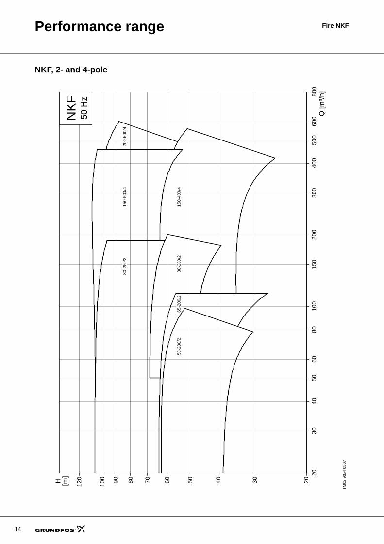
Performance range
NKF, 2- and 4-pole
TM02
935
4 05
07
2030
4050
6080
100
150
200
300
400
500
600
800
Q [m
³/h]
2030405060708090100
120
[m]
H
NK
F50
Hz
150-
400/
4
150-
500/
480
-250
/220
0-50
0/4
65-2
00/2
80-
200/
250
-200
/2

15
Fire NKFProduct range
Product numbersThe product numbers are reference numbers for the Fire NKF pump unit version. All Fire NKF pump units receive a unique product number specified according to the order.
As standard, all Fire NKF pumps are with standard coupling. Fire pumps with spacer coupling are available on demand.
*) Two different impeller diameters for the same motor size, see page 30.
VdS approval numbers
The standard range has been composed on the basis of the following parameters:
• Pump housings have discharge flanges from DN 20 to DN 50.
• Impellers are made of bronze.• Neck rings are made of bronze.The Fire NKF pump units are available in the following versions:
*) The controller is without monitoring module and controller options. See section Controller, page 48.
Pump unit Motor powerP2 [kW] Basic unit Compact unit Flex unit
Fire NKF 50-200 15 96157405 96273574 9627360518.5 96157406 96273575 9627360622 96157407 96273576 9627360730 96157408 96273577 96273608
Fire NKF 65-200 18.5 96157409 96273578 9627360922 96157410 96273579 9627361030 96157411 96273580 96273611
37* 9615741296157413
9627358196273582
9627361296273613
Fire NKF 80-200 30 96157414 96273583 9627361437 96157415 96273584 9627361545 96157416 96273585 9627361655 96157417 96273586 96273617
Fire NKF 80-250 45 96157418 96273587 9627361855 96157419 96273588 9627361975 96157420 96273589 9627362090 96157421 96273590 96273621
Fire NKF 150-400 45 96702927 96740889 9670293755 96702928 96740890 9670293875 96702929 96740891 9670293990 96702930 96740892 96702940110 96702931 - 96702941
Fire NKF 150-500 110 96702932 - 96702942132 96702933 - 96702943160 96702934 - 96702944200 96702935 - 96702945250 96702936 - 96702946
Fire NKF 200-500 132 96157432 - 96273632160 96157433 - 96273633200 96157434 - 96273634250 96157435 - 96273635
Pump VdS Approval NoNKF 50-200 P 4050056NKF 65-200 P 4050057NKF 80-200 P 4050058NKF 80-250 P 4050059NKF 150-400 P 4060069NKF 150-500 P 4070013NKF 200-500 P 4050089
Basic unit: Pump and motor mounted on base frame.
Compact unit: Pump, motor and controller * mounted on base frame.
Flex unit: Pump and motor mounted on base frame, and controller * for wall mounting. As standard, the flex unit is delivered with a 5 m cable between pump and controller. Other lengths are available on demand.

Fire NKF
16
Identification
Type keyFire system
Shaft sealsNKF pumps are supplied with BAQE shaft seals.
Codes for shaft sealsPositions (1) to (4) cover four pieces of information about the shaft seal:
The following table gives a short description of positions (1), (2), (3) and (4).
NameplateThe nameplate shows a Fire NKF with a rated flow of 150 m3/h at 2940 min-1. To deliver a rated head of 112 metres, the actual impeller diameter is 270 mm. See fig. 8.
Fig. 8 Example of Fire NKF nameplate
Example Fire NK F 32 -125 /142 E -F -X -D -B -A -BFire: Fire system
Pump typeNK
F: Pump approved for fire fighting
Nominal diameter of discharge port (DN)[mm]
Pump housing size[mm]
Actual impeller diameter[mm]
DriverE: Electric motor, 50 Hz
Approval of pumpF: VdS
Approval of unitX: No approval
Pipe connectionD: DIN
ControllerB: For mounting on base frameW: For wall mountingX: No controller
Shaft sealA: BAQE
CouplingA: StandardB: Spacer
Example (1) (2) (3) (4)Grundfos type designation
Material, rotating seal face
Material, stationary seat
Material, secondary seal and other rubber and composite parts, except the neck ring
Pos. Type Short description of seal(1) B Rubber bellows seal
Pos. Type Material Synthetic carbons:
(2) and (3)
A Carbon, metal-impregnated (antimony (not approved for potable water))
Q Silicon carbidePos. Type Material(4) E EPDM
TMType:part No.serial No.
Main Supply:
impeller diameter:
Made in Germany P1Made in Germany P1 06400640
VdSpump VdS-approved
Fire NKF 80-250/270-E-F-X-D-B-A-B96157421123456789
6554
2145
6245
65
6554
2145
6245
65
3X400V 50Hz
270
min2940n:55 kWP2:kg346G:55IP
Q: H: 112 m150 m /h3
-1

Fire NKFConstruction
Sectional drawing, NKF, model B
Fig. 9 Sectional drawing, NKF 50-200, 65-200, 80-200, 80-250
Material specificationTM
01 7
888
0203
159f5351865449206
72a 7711a 159f10566a 6667 20
Pos. Component Material specification6 Pump housing EN-GJL-250
11a Key Stainless steelDIN W.-Nr. 1.4301/AISI 304
20 Plug (drain, priming) DIN W.-Nr. 1.115249 Impeller G-CuSn5Zn5Pb5
51 Shaft Stainless steelDIN W.-Nr. 1.4021/AISI 420
53 Ball bearing SKF - FAG - NSK54 Ball bearing SKF - FAG - NSK
66 Washer Stainless steelDIN W.-Nr. 1.4305/AISI 303
66a Spring washer Stainless steel 1.4310
67 Nut Stainless steelDIN W.-Nr. 1.4301/AISI 304
72a O-ring O-ring, EPDM or FKM77 Cover EN-GJL-25086 Bearing bracket EN-GJL-250
105 Mechanical shaft seal Burgmann mechanical seals159f Retaining ring
17

18
Construction Fire NKF
Sectional drawing, NKF, model A
Fig. 10 Sectional drawing, NKF 200-500
Material specificationTM
01 3
279
0203
Pos. Component Material specification Pos. Component Material specification1111 Pump housing
EN-GJL-2503110 Bearing housing EN-GJL-250
1222 Seal box 3120 Ball bearingSKF - FAG - RHP - NSK 1510 Wear ring
G-CuPb10Sn3121 Ball bearing
1520 Wear ring 3131 Ball bearing
1850 Impeller counter nut
Stainless steelDIN W.-Nr. 1.4301/AISI 304 4200 Rotary seal ring Burgmann mechanical seals
2002 Spacer ring Stainless steelDIN W.-Nr. 1.4021/AISI 420 4201 Stationary seat
2110 Shaft Stainless steelDIN W.-Nr. 1.4021/AISI 420 4213 Cover for seal EN-GJL-250
2200 Impeller G-CuSn5Zn5Pb5 4522 Gasket for cover Asbestos free gasketsDIN FA 3535 and FKM
2450 Shaft sleeve Stainless steelDIN W.-Nr. 1.4021/AISI 420 4596 Gasket for pump Asbestos free gaskets
DIN FA 3535 and FKM2540 Thrower 6511 Priming plug
DIN W.-Nr. 1.00372542 Thrower 6515 Drain plug
2911 Impeller washer Stainless steelDIN W.-Nr. 1.4021/AISI 420 6521 Pressure tapping
plug2912 Impeller nut 6710 Impeller key DIN W.-Nr. 1.1181
2915 Lock nut Stainless steelDIN W.-Nr. 1.4301/AISI 304

Construction Fire NKF
Mechanical constructionPump housingThe cast iron volute pump housing has axial suction port and radial discharge port. Flange dimensions are according to EN 1092-2.
The pump housings have both a priming and a drain hole closed by plugs.
Fig. 11 NKF pump housing
Bearing bracket and shaftThe bearing bracket has two sturdy, antifriction, lubricated-for-life bearings. However, oversize pumps with 55 mm shaft diameter have open bearings with lubricating nipples.
The bearing bracket is made of cast iron, EN-GJL-250.
The shaft is made of stainless steel, DIN W.-Nr. 1.4021/AISI 420. Shaft diameter d5 is either ∅24, 32 or 55.
A thrower on the shaft prevents water from entering the bearing bracket.
Fig. 12 Bearing bracket and shaft
All NKF pumps are fitted with one of four shaft, shaft seal and bearing sizes.
Shaft sealThe shaft seal is an unbalanced, mechanical shaft seal with dimensions to EN 12 756. Seal faces are available in a variety of combinations. The code of the standard version is BAQE, see page 16.
The drawings below illustrate shaft seals for NKF, model A.
Fig. 13 Rubber bellows seal type BAQE counteracts deposits from the pumped water
CouplingNKF pumps are available with two types of coupling:
• standard • spacer.
Fig. 14 Standard coupling
Fig. 15 Spacer coupling
Pumps fitted with a spacer coupling can be serviced without dismantling the motor from the base frame and without removing the pump housing from the pipework. This saves realignment of pump and motor after service.
TM03
023
2 45
04TM
03 0
233
4504
TM02
602
2 48
02TM
03 0
235
4504
TM03
023
4 45
04
19

20
Construction Fire NKF
ImpellerThe closed impeller is made of bronze and has double-curved blades with smooth surfaces for high efficiency.
Fig. 16 Impeller for an NKF pump
All impellers are dynamically and hydraulically balanced. The hydraulical balancing compensates for axial thrust.
The direction of rotation of the impeller is clockwise when viewed from the motor.
All impellers are adapted to the duty point required by the customer.
Base framePump and motor are mounted on a common, steel base frame.
Fig. 17 Schematic view of NKF pump-motor unit mounted on a base frame
Surface treatmentNKF, model BThe cast iron parts of NKF pumps are electrocoated.
The electrocoating process includes:
1. Alkaline cleaning.2. Pre-treatment with zinc phosphate coating.3. Cathodic electrocoating (epoxy).4. Curing of paint film at 200-250 °C.
The colour code is NCS 9000/RAL 9005.5. Final spray-painting with red two-component paint,
RAL 3000.
NKF, model AAll stationary cast iron parts are dip-painted with waterbased, ether-epoxy, no-lead paint (NCS 9000/ RAL 9005). The thickness of the film is 25 μm ± 5 μm. The product is also spray-painted with black waterbased, ether-epoxy, no-lead paint and finally with red two-component paint, Ral 3000. The thickness of the dry coating is 35 μm ± 5 μm.
Test pressurePressure testing has been made with +20 °C water containing corrosion inhibitor.
MotorThe motor is a totally enclosed, fan-cooled, standard motor with main dimensions according to IEC and DIN standards.
The tables below show the motors available for NKF.
Standard motor range
Grey squares = These motors are not in use.
TM03
023
1 45
04TM
03 0
199
0203
• • • • • • • • • • • • • • • • • • • • • • • • • • • • • • • • • • • • • • • • • • • • • • • • • • • • • • • • • • • • • • • • • • • • • • • • • • • • • • • • • • • • • • • • • • • • • • • • • • • • • • • • • • • • • • • • • • • • • • • • • • • • • • • • • • • • • • • • • • • • • • • • • • • • • • • • • • • • • • • • • • • • • • • • • • • • • • • •• • • • • • • • • • • • • • • • • • • • • • • • • • • • • • • • • • • • • • • • • • • • • • • • • • • • • • • • • • • • • • • • • • • • • • • • • • • • • • • • • • • • • • • • • • • • • • • • • • • • • • • • • • • • • • • • • • • • • • • • • • • • • • • • • • • • • • • • • • • • • • • • • • • • • • • • • • • • • • • • • • • • • • • • • • • • • • •
• • • • • • • • • • • • • • • • • • • • • • • • • • • • • • • • • • • • • • • • • • • • • • • • • • • • • • • • • • • • • • • • • • • • • • • • • • • • • • • • • • • • • • • • • • • • • • • • • • • • • • • • • • • • • • • • • • • • • • • • • • • • • • • • • • • • • • • • • • • • • • • • • • • • • • • • • • • • • • • • • • • • • • • • • • • • • • • •• • • • • • • • • • • • • • • • • • • • • • • • • • • • • • • • • • • • • • • • • • • • • • • • • • • • • • • • • • • • • • • • • • • • • • • • • • • • • • • • • • • • • • • • • • • • • • • • • • • • • • • • • • • • • • • • • • • • • • • • • • • • • • • • • • • • • • • • • • • • • • • • • • • • • • • • • • • • • • • • • • • • • • • • • • • • • • •
• • • • • • • • • • • • • • • • • • • • • • • • • • • • • • • • • • • • • • • • • • • • • • • • • • • • • • • • • • • • • • • • • • • • • • • • • • • • • • • • • • • • • • • • • • • • • • • • • • • • • • • • • • • • • • • • • • • • • • • • • • • • • • • • • • • • • • • • • • • • • • • • • • • • • • • • • • • • • • • • • • • • • • • • • • • • • • • •• • • • • • • • • • • • • • • • • • • • • • • • • • • • • • • • • • • • • • • • • • • • • • • • • • • • • • • • • • • • • • • • • • • • • • • • • • • • • • • • • • • • • • • • • • • • • • • • • • • • • • • • • • • • • • • • • • • • • • • • • • • • • • • • • • • • • • • • • • • • • • • • • • • • • • • • • • • • • • • • • • • • • • • • • • • • • • •
• • • • • • • • • • • • • • • • • • • • • • • • • • • • • • • • • • • • • • • • • • • • • • • • • • • • • • • • • • • • • • • • • • • • • • • • • • • • • • • • • • • • • • • • • • • • • • • • • • • • • • • • • • • • • • • • • • • • • • • • • • • • • • • • • • • • • • • • • • • • • • • • • • • • • • • • • • • • • • • • • • • • • • • • • • • • • • • •• • • • • • • • • • • • • • • • • • • • • • • • • • • • • • • • • • • • • • • • • • • • • • • • • • • • • • • • • • • • • • • • • • • • • • • • • • • • • • • • • • • • • • • • • • • • • • • • • • • • • • • • • • • • • • • • • • • • • • • • • • • • • • • • • • • • • • • • • • • • • • • • • • • • • • • • • • • • • • • • • • • • • • • • • • • • • • •
• • • • • • • • • • • • • • • • • • • • • • • • • • • • • • • • • • • • • • • • • • • • • • • • • • • • • • • • • • • • • • • • • • • • • • • • • • • • • • • • • • • • • • • • • • • • • • • • • • • • • • • • • • • • • • • • • • • • • • • • • • • • • • • • • • • • • • • • • • • • • • • • • • • • • • • • • • • • • • • • • • • • • • • • • • • • • • • •• • • • • • • • • • • • • • • • • • • • • • • • • • • • • • • • • • • • • • • • • • • • • • • • • • • • • • • • • • • • • • • • • • • • • • • • • • • • • • • • • • • • • • • • • • • • • • • • • • • • • • • • • • • • • • • • • • • • • • • • • • • • • • • • • • • • • • • • • • • • • • • • • • • • • • • • • • • • • • • • • • • • • • • • • • • • • • •
• • • • • • • • • • • • • • • • • • • • • • • • • • • • • • • • • • • • • • • • • • • • • • • • • • • • • • • • • • • • • • • • • • • • • • • • • • • • • • • • • • • • • • • • • • • • • • • • • • • • • • • • • • • • • • • • • • • • • • • • • • • • • • • • • • • • • • • • • • • • • • • • • • • • • • • • • • • • • • • • • • • • • • • • • • • • • • • •• • • • • • • • • • • • • • • • • • • • • • • • • • • • • • • • • • • • • • • • • • • • • • • • • • • • • • • • • • • • • • • • • • • • • • • • • • • • • • • • • • • • • • • • • • • • • • • • • • • • • • • • • • • • • • • • • • • • • • • • • • • • • • • • • • • • • • • • • • • • • • • • • • • • • • • • • • • • • • • • • • • • • • • • • • • • • • •
• • • • • • • • • • • • • • • • • • • • • • • • • • • • • • • • • • • • • • • • • • • • • • • • • • • • • • • • • • • • • • • • • • • • • • • • • • • • • • • • • • • • • • • • • • • • • • • • • • • • • • • • • • • • • • • • • • • • • • • • • • • • • • • • • • • • • • • • • • • • • • • • • • • • • • • • • • • • • • • • • • • • • • • • • • • • • • • •• • • • • • • • • • • • • • • • • • • • • • • • • • • • • • • • • • • • • • • • • • • • • • • • • • • • • • • • • • • • • • • • • • • • • • • • • • • • • • • • • • • • • • • • • • • • • • • • • • • • • • • • • • • • • • • • • • • • • • • • • • • • • • • • • • • • • • • • • • • • • • • • • • • • • • • • • • • • • • • • • • • • • • • • • • • • • • •
• • • • • • • • • • • • • • • • • • • • • • • • • • • • • • • • • • • • • • • • • • • • • • • • • • • • • • • • • • • • • • • • • • • • • • • • • • • • • • • • • • • • • • • • • • • • • • • • • • • • • • • • • • • • • • • • • • • • • • • • • • • • • • • • • • • • • • • • • • • • • • • • • • • • • • • • • • • • • • • • • • • • • • • • • • • • • • • •• • • • • • • • • • • • • • • • • • • • • • • • • • • • • • • • • • • • • • • • • • • • • • • • • • • • • • • • • • • • • • • • • • • • • • • • • • • • • • • • • • • • • • • • • • • • • • • • • • • • • • • • • • • • • • • • • • • • • • • • • • • • • • • • • • • • • • • • • • • • • • • • • • • • • • • • • • • • • • • • • • • • • • • • • • • • • • •
• • • • • • • • • • • • • • • • • • • • • • • • • • • • • • • • • • • • • • • • • • • • • • • • • • • • • • • • • • • • • • • • • • • • • • • • • • • • • • • • • • • • • • • • • • • • • • • • • • • • • • • • • • • • • • • • • • • • • • • • • • • • • • • • • • • • • • • • • • • • • • • • • • • • • • • • • • • • • • • • • • • • • • • • • • • • • • • •• • • • • • • • • • • • • • • • • • • • • • • • • • • • • • • • • • • • • • • • • • • • • • • • • • • • • • • • • • • • • • • • • • • • • • • • • • • • • • • • • • • • • • • • • • • • • • • • • • • • • • • • • • • • • • • • • • • • • • • • • • • • • • • • • • • • • • • • • • • • • • • • • • • • • • • • • • • • • • • • • • • • • • • • • • • • • • •
• • • • • • • • • • • • • • • • • • • • • • • • • • • • • • • • • • • • • • • • • • • • • • • • • • • • • • • • • • • • • • • • • • • • • • • • • • • • • • • • • • • • • • • • • • • • • • • • • • • • • • • • • • • • • • • • • • • • • • • • • • • • • • • • • • • • • • • • • • • • • • • • • • • • • • • • • • • • • • • • • • • • • • • • • • • • • • • •
Pressure stage
Operating pressure Test pressurebar MPa bar MPa
PN 10 10 1.0 15 1.5PN 16 16 1.6 24 2.4
Standard rangeOutputP2 [kW] 2-pole 4-pole
11.0
MMG model E
15.018.522.030.037.045.0
MMG model E
55.075.090.0
132.0160.0200.0250.0

21
Fire NKFOperating conditions
Pump unit locationThe pump is designed for installation in a non-aggressive and non-explosive atmosphere.
The relative air humidity must not exceed 95 %.
Ambient temperature and altitudeThe ambient temperature must not exceed +40 °C.
If the ambient temperature exceeds +40 °C or if the motor is installed more than 1000 metres above sea level, the rated motor output will fall due to the low density and consequently low cooling effect of the air. In such cases, it may be necessary to use an oversize motor with a higher output. See fig. 18.
Fig. 18 The motor P2 depends on temperature/altitude
Duty range of shaft sealThe NKF pump is equipped with a BAQE shaft seal, i.e. a rubber bellows seal with metal-impregnated carbon/silicon carbide seal faces and EPDM rubber parts.
Temperature range: 0 °C to +120 °C.
Inlet pressure
Maximum inlet pressureThe inlet pressure is limited by the maximum operating pressure. The maximum inlet pressure appears from this table:
Minimum inlet pressureThe minimum inlet pressure must be according to the NPSH curve + a safety margin of at least 1 metre + correction for vapour pressure, according to VdS CEA 4001 : 2005-09 (02).
See fig. 19.
Fig. 19 Schematic view of open system with NKF pump
TM00
218
9 15
98
20 25 30 35 40 45 50 55 60 65 70 75 80
50
60
70
80
90
100
[%]P2
t [°C]
1000 2250 3500 m
Inlet pressureMax. 9 bar.Max. 7 bar for impellers of 400 mm and up.
TM03
295
7 49
05
Fire NKF
22
Installation and operation
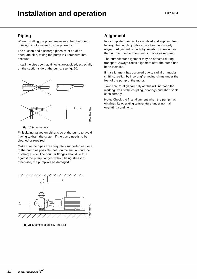
PipingWhen installing the pipes, make sure that the pump housing is not stressed by the pipework.
The suction and discharge pipes must be of an adequate size, taking the pump inlet pressure into account.
Install the pipes so that air locks are avoided, especially on the suction side of the pump. see fig. 20.
Fig. 20 Pipe sections
Fit isolating valves on either side of the pump to avoid having to drain the system if the pump needs to be cleaned or repaired.
Make sure the pipes are adequately supported as close to the pump as possible, both on the suction and the discharge side. The counter flanges should lie true against the pump flanges without being stressed; otherwise, the pump will be damaged.
Fig. 21 Example of piping, Fire NKF
AlignmentIn a complete pump unit assembled and supplied from factory, the coupling halves have been accurately aligned. Alignment is made by inserting shims under the pump and motor mounting surfaces as required.
The pump/motor alignment may be affected during transport. Always check alignment after the pump has been installed.
If misalignment has occurred due to radial or angular shifting, realign by inserting/removing shims under the feet of the pump or the motor.
Take care to align carefully as this will increase the working lives of the coupling, bearings and shaft seals considerably.
Note: Check the final alignment when the pump has obtained its operating temperature under normal operating conditions.
TM00
226
3 33
93TM
03 2
998
5005

23
Fire NKFMotor data
The tables below show technical data on 2- and 4-pole motors for NKF pumps.
Fig. 22 MMG motor, model E
Motor range, 2-pole
Motor range, 4-pole
GR
7350
Frame size Voltage P2[kW]
I1/1 [A]
η[%] Cos ϕ 1/1
n [min-1]
Weight[kg]
MMG 160 MA-E
3 x 380-415 Δ/660-690 Y
11 19.6/11.4 88.4 0.90 2930 6.6 115MMG 160 MB-E 15 26.5/15.4 89.4 0.90 2940 6.5 123MMG 160 L-E 18.5 33.0/19.2 90.0 0.90 2940 7.2 146MMG 180 M-E 22 39.0/22.6 90.5 0.90 2940 7.4 183MMG 200 LA-E 30 53.5/31.0 91.4 0.88 2950 7.2 248MMG 200 LB-E 37 64.5/37.5 92.0 0.89 2950 7.9 270MMG 225 M-E 45 78.0/45.0 92.5 0.89 2970 7.9 346MMG 250 M-E 55 94.5/55.0 93.0 0.90 2960 6.2 462MMG 280 S-E 75 128/74.0 96.6 0.88 2980 6.6 525MMG 280 M-E 90 160/92.5 93.9 0.89 2980 7.2 590
Frame size Voltage P2 [kW]
I1/1 [A]
η[%] Cos ϕ 1/1
n [min-1]
Weight[kg]
MMG 225 M-E
3 x 380-415 Δ/660-690 Y
45 78.5/45.5 92.5 0.88 1480 7.98 350MMG 250 M-E 55 94.5/54.5 93.0 0.89 1480 7.5 470MMG 280 S-E 75 126/73.0 93.6 0.90 1480 7.4 554MMG 280 M-E 90 152/88.0 93.9 0.91 1480 6.88 600MMG 315 S-E 110 192/110 94.5 0.88 1490 6.25 965MMG 315 M-E 132 226/130 94.8 0.89 1490 6.8 1120MMG 315 LA-E 160 270/156 94.9 0.89 1480 5.91 1200MMG 315 LB-E 200 340/196 95.0 0.89 1480 5.57 1295MMG 355 M-E 250 415/240 95.3 0.91 1490 6.36 1650
IStartI1 1⁄-------------
IStartI1 1⁄-------------

24
Fire NKFBare shaft pumps
NKF, model B
TM03
813
4 06
07
E Drain plugM Pressure gauge connection
f xa
ws2
d5
DN
s
c
h1
h2
b
s1
l
t
n
n2
n3
n1
M
MDNd
m2
m1
Type
Pump [mm] Supporting feet [mm] Shaft [mm] Pump moments of inertia
[kgm2]
Weight[kg]DNs DNd a f h1 h2 M, E b m1 m2 n1 n2 w S1 S2 c d5 l x t n
NKF 50-200 65 50 100 360 160 200 3/8" 50 100 70 265 212 260 M12 M12 18 24 50 100 27 8 0.206 56
NKF 65-200 80 65 100 360 180 225 3/8" 65 125 95 320 250 260 M12 M12 19 24 50 140 27 8 0.260 55NKF 80-200
100 80 125 470180 250
3/8"65 125 95 345 280
340M12
M1219
32 80 140 35 100.401 73
NKF 80-250 200 280 80 160 120 400 315 M16 23 0.724 93NKF 150-400
200 150160 530 315 450
1/2"100
200 150550 450 370
M20M12 28 42
110140 45 12 0.835 286
NKF 150-500 180 670 400 500 125 625 500 500 M16 43 60 180 64 18 1.504 522

Bare shaft pumps Fire NKF
NKF, model A
TM03
813
5 06
07
n
// //
n1
n2
VG 1/4
G 3/8250-500
t
m2
m1
s1
b
EG 1/4
h2
h1
c
G 1/2
A
DN
s
G 1/4
M
DNd
300
20
w300
s2
l
xfa
330
280
d5
A Priming plugE Drain plugM Pressure gauge connectionV Pressure/vacuum gauge connection
Type
Pump [mm] Supporting feet [mm] Shaft [mm] Pump moments of inertia
[kgm2]
Weight[kg]DNs DNd a f h1 h2 b c m1 m2 n1 n2 s1 s2 w d5 l t n x
NKF 200-500 250 200 250 750 410 675 140 22 250 190 790 660 28 24 536 55 140 59 16 180 14.3 480
25
26
Bare shaft pumps Fire NKF
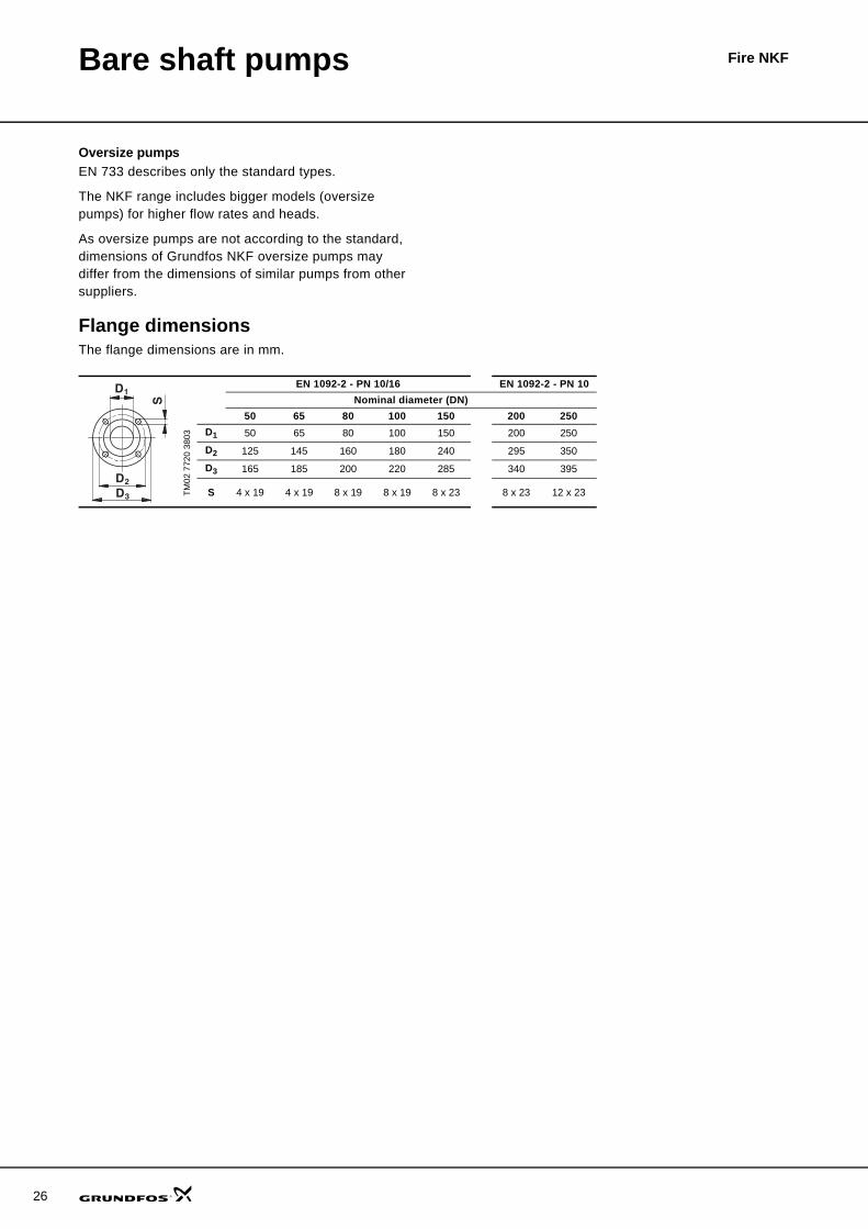
Oversize pumpsEN 733 describes only the standard types.
The NKF range includes bigger models (oversize pumps) for higher flow rates and heads.
As oversize pumps are not according to the standard, dimensions of Grundfos NKF oversize pumps may differ from the dimensions of similar pumps from other suppliers.
Flange dimensionsThe flange dimensions are in mm.
TM02
772
0 38
03
EN 1092-2 - PN 10/16 EN 1092-2 - PN 10Nominal diameter (DN)
50 65 80 100 150 200 250D1 50 65 80 100 150 200 250
D2 125 145 160 180 240 295 350
D3 165 185 200 220 285 340 395
S 4 x 19 4 x 19 8 x 19 8 x 19 8 x 23 8 x 23 12 x 23
S
D2
D3
D1

Fire NKFCurve charts
How to read the curve charts
TM03
166
7
0 20 40 60 80 100 120 140 160 180 200 220 240 260 280 300 320Q [m³/h]
15
20
25
30
35
40
45
50
55
60
65
70
[m]H
0 500 1000 1500 2000 2500 3000 3500 4000 4500 5000 Q [l/min]
NKF 80-200
ISO 9906 Annex A
2-pole, 50 Hz
ø188
ø202
ø213
ø222
55 kW
45 kW
37 kW
30 kW
0 20 40 60 80 100 120 140 160 180 200 220 240 260 280 300 320Q [m³/h]
0
10
20
30
40
50
[kW]P2
0
5
10
15
20
NPSH[m]
ø188 (Min. NPSH) ø222 (Max. NPSH)
ø188
ø202
ø213
ø222
Pump type and frequency of motor
Size of impeller
Total pump head H = Htotal
The power curve indicates pump input power [P2]
The NPSH curves are according to the minimum and maximum impeller diameter
QH curve for the individual pump Qzul indicates the limit of the individual pump
performance range according to VdS
27

28
Curve charts Fire NKF
Curve conditions
Selection of pumpsThe guidelines below apply to the curves shown in the performance charts, pages 29 to 35.
• Tolerances according to ISO 9906, Annex A and VdS 2100.
• The curves show pump performance with different impeller diameters at the nominal speed.
• The bold part of the curves shows the recommended operating range.
• The thin parts are not allowed according to VdS.• Do not use the pumps at minimum flows below
0.1 x Q at optimum efficiency because of the danger of overheating of the pump.
• The curves apply to the pumping of water at a temperature of +20 °C and a kinematic viscosity of 1 mm2/s (1 cSt).
• NPSH: The curves are according to the minimum and maximum impeller diameter.
• In case of other densities than 1000 kg/m3 the discharge pressure is proportional to the density.
• When pumping water with a density higher than 1000 kg/m3, motors with correspondingly higher outputs must be used.
Calculation of total headThe total pump head consists of the height difference between the measuring points + the differential head + the dynamic head.
Performance testsThe requested duty point for every pump is tested according to ISO 9906, Annex A, and VdS 2100.
If the customer requires a specific impeller diameter (not a specific duty point), the pump will be tested at a duty point which is 2/3 of the maximum flow of the published performance curve related to the ordered impeller diameter (according to ISO 9906, Annex A).
If the customer requires either more points on the curve to be checked or certain minimum performances or certificates, individual measurements must be made.
VdS certificateThe pump order includes a test certificate confirming the required QH performance.
Hgeo: Height difference between measuring points.
Hstat: Differential head between the suction and the discharge side of the pump.
Hdyn: Calculated values based on the velocity of the pumped water on the suction and the discharge side of the pump.
Htotal Hgeo Hstat Hdyn+ +=

Performance curves
NKF 50-200, 2-pole
Circulation flow 2 % of rated flow.
TM03
178
0 31
05
0 10 20 30 40 50 60 70 80 90 100 110 120 130 Q [m³/h]
4
8
12
16
20
24
28
32
36
40
44
48
52
56
60
64
68[m]H
0 500 1000 1500 2000 Q [l/min]
NKF 50-200
ISO 9906 Annex A
2-pole, 50 Hz
ø170
ø194
ø207
ø219
22 kW
18,5 kW
15 kW
11 kW
0 10 20 30 40 50 60 70 80 90 100 110 120 130 Q [m³/h]
0
4
8
12
16
20
24
[kW]P2
0
4
8
12
16
20
NPSH[m]
ø170
ø194
ø207
ø219
ø170 (Min. NPSH)
ø219 (Max. NPSH)
NKF 50-200> ∅207 ≤ ∅219 22 kW 2950 rpm> ∅194 ≤ ∅207 18.5 kW 2940 rpm> ∅170 ≤ ∅194 15 kW 2940 rpm= ∅170 11 kW 2930 rpm
NKF 50-2002-pole
29
30
NKF 65-2002-polePerformance curves
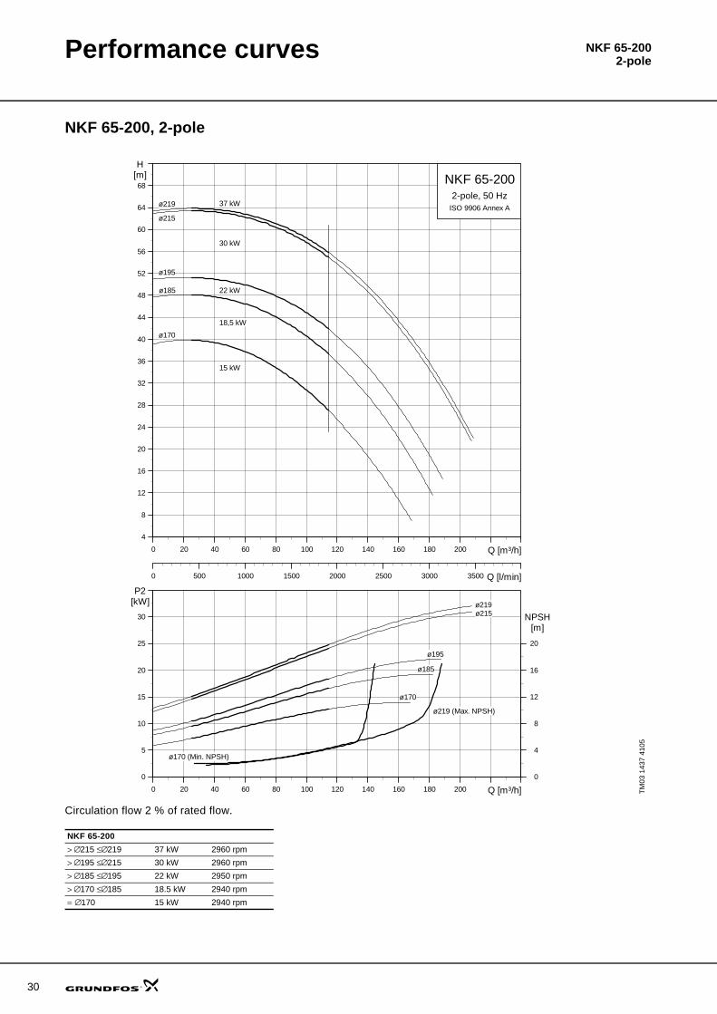
NKF 65-200, 2-pole
Circulation flow 2 % of rated flow.
TM03
143
7 41
05
0 20 40 60 80 100 120 140 160 180 200 Q [m³/h]
4
8
12
16
20
24
28
32
36
40
44
48
52
56
60
64
68[m]H
0 500 1000 1500 2000 2500 3000 3500 Q [l/min]
NKF 65-200
ISO 9906 Annex A
2-pole, 50 Hz
ø170
ø185
ø195
ø215
ø219 37 kW
30 kW
22 kW
18,5 kW
15 kW
0 20 40 60 80 100 120 140 160 180 200 Q [m³/h]
0
5
10
15
20
25
30
[kW]P2
0
4
8
12
16
20
NPSH[m]
ø170 (Min. NPSH)
ø170
ø185
ø195
ø215ø219
ø219 (Max. NPSH)
NKF 65-200> ∅215 ≤ ∅219 37 kW 2960 rpm> ∅195 ≤ ∅215 30 kW 2960 rpm> ∅185 ≤ ∅195 22 kW 2950 rpm> ∅170 ≤ ∅185 18.5 kW 2940 rpm= ∅170 15 kW 2940 rpm

NKF 80-2002-polePerformance curves
NKF 80-200, 2-pole
Circulation flow 2 % of rated flow.
TM03
166
7 44
05
0 20 40 60 80 100 120 140 160 180 200 220 240 260 280 300 320Q [m³/h]
15
20
25
30
35
40
45
50
55
60
65
70
[m]H
0 500 1000 1500 2000 2500 3000 3500 4000 4500 5000 Q [l/min]
NKF 80-200
ISO 9906 Annex A
2-pole, 50 Hz
ø188
ø202
ø213
ø222
55 kW
45 kW
37 kW
30 kW
0 20 40 60 80 100 120 140 160 180 200 220 240 260 280 300 320Q [m³/h]
0
10
20
30
40
50
[kW]P2
0
5
10
15
20
NPSH[m]
ø188 (Min. NPSH) ø222 (Max. NPSH)
ø188
ø202
ø213
ø222
NKF 80-200> ∅213 ≤ ∅222 55 kW 2960 rpm> ∅202 ≤ ∅213 45 kW 2980 rpm> ∅188 ≤ ∅202 37 kW 2960 rpm= ∅188 30 kW 2960 rpm
31

32
NKF 80-2502-polePerformance curvesPerformance curves
NKF 80-250, 2-pole
Circulation flow 2 % of rated flow.
TM03
221
7 39
05
0 40 80 120 160 200 240 280 320 360 Q [m³/h]
10
20
30
40
50
60
70
80
90
100
110
[m]H
0 1000 2000 3000 4000 5000 6000 Q [l/min]
NKF 80-250
ISO 9906 Annex A
2-pole, 50 Hz
ø216
ø233
ø255
ø270
90 kW
75 kW
55 kW
45 kW
0 40 80 120 160 200 240 280 320 360 Q [m³/h]
0
20
40
60
80
100
[kW]P2
0
5
10
15
20
NPSH[m]
ø216 (Min. NPSH)
ø270 (Max. NPSH)
ø216
ø233
ø255
ø270
NKF 80-250> ∅255 ≤ ∅270 90 kW 2980 rpm> ∅233 ≤ ∅255 75 kW 2970 rpm> ∅218 ≤ ∅233 55 kW 2960 rpm= ∅218 45 kW 2980 rpm

NKF 150-4004-polePerformance curves
NKF 150-400, 4-pole
Circulation flow 2 % of rated flow.
TM03
547
8 41
06
0 100 200 300 400 500 600 700 Q [m³/h]
0
5
10
15
20
25
30
35
40
45
50
55
60
65
[m]H
0 2000 4000 6000 8000 10000 Q [l/min]
NKF 150-400
ISO 9906 Annex A
4-pole, 50 Hz
ø318
ø335
ø368
ø389
ø410
45 kW
55 kW
75 kW
90 kW
110 kW
0 100 200 300 400 500 600 700 Q [m³/h]
0
20
40
60
80
100
120
[kW]P2
0
5
10
15
20
NPSH[m]
ø318 (Min. NPSH)ø410 (Max. NPSH)
ø318
ø335
ø368
ø389
ø410
NKF 150-400> ∅389 ≤ ∅410 110 kW 1490 rpm> ∅368 ≤ ∅389 90 kW 1480 rpm> ∅335 ≤ ∅368 75 kW 1480 rpm> ∅318 ≤ ∅335 55 kW 1480 rpm> ∅318 45 kW 1480 rpm
33

34
NKF 150-5004-polePerformance curves
NKF 150-500, 4-pole
Circulation flow 2 % of rated flow.
TM03
805
8 03
07
0 100 200 300 400 500 600 700 800Q [m³/h]
0
10
20
30
40
50
60
70
80
90
100
110
120
[m]H
0 2000 4000 6000 8000 10000 12000 Q [l/min]
NKF 150-500
ISO 9906 Annex A
4-pole, 50 Hz
/415
/441
/476
/518
/538
250 kW
200 kW
160 kW
132 kW
110 kW
0 100 200 300 400 500 600 700 800Q [m³/h]
0
40
80
120
160
200
240
[kW]P2
0
10
20
NPSH[m]
/415 (Min. NPSH) /538 (Max. NPSH)
/415
/441
/476
/518
/538
NKF 150-500> ∅518 ≤ ∅538 250 kW 1490 rpm> ∅476 ≤ ∅518 200 kW 1480 rpm> ∅441 ≤ ∅476 160 kW 1480 rpm> ∅415 ≤ ∅441 132 kW 1480 rpm> ∅415 110 kW 1480 rpm

NKF 200-5004-polePerformance curves
NKF 200-500, 4-pole
Circulation flow 2 % of rated flow.
TM03
249
9 44
05
0 100 200 300 400 500 600 700 800 Q [m³/h]
0
10
20
30
40
50
60
70
80
90
100
110
[m]H
0 2000 4000 6000 8000 10000 12000 14000 Q [l/min]
NKF 200-500
ISO 9906 Annex A
4-pole, 50 Hz
ø446
ø471
ø512
ø530
132 kW
160 kW
200 kW
250 kW
0 100 200 300 400 500 600 700 800 Q [m³/h]
0
50
100
150
200
250
[kW]P2
0
5
10
15
20
NPSH[m]
ø446 (Min. NPSH) ø530 (Max. NPSH)
ø446
ø471
ø512
ø530
NKF200-500> ∅512 ≤ ∅530 250 kW 1490 rpm> ∅471 ≤ ∅512 200 kW 1490 rpm> ∅446 ≤ ∅471 160 kW 1490 rpm= ∅446 132 kW 1490 rpm
35

36
Technical data
Installation dimensions
Fire NKF 50-200, basic unit
With MMG-E motor, 2-pole
TM03
292
9 49
05
Fire NKF 50-200kW 11 15 18.5 22Motor range MMG160MA-E MMG160MB-E MMG160ML-E MMG180M-EPN [bar] 16 16 16 16DNd [mm] 50 50 50 50DNs [mm] 65 65 65 65a [mm] 100 100 100 100a1 [mm] 150 150 150 150
a2 [mm] 60 60 60 60
a3 [mm] 300 300 300 300
h [mm] 100 100 100 100h2 [mm] 200 200 200 200
h3 [mm] 260 260 260 280
L [mm] 1072 1072 1116 1154L1 [mm] 1200 1200 1200 1200
L2 [mm] 750 750 750 750
b2 [mm] 790 790 790 790
b3 [mm] 740 740 740 740
d [mm] 13 13 13 13Net weight [kg] 223 231 254 292
Fire NKF 50-2002-pole

Fire NKF 50-2002-poleTechnical data
Fire NKF 50-200, compact unit
With MMG-E motor, 2-pole
TM03
293
0 49
05 Fire NKF 50-200kW 11 15 18.5 22Motor range MMG160MA-E MMG160MB-E MMG160ML-E MMG180M-EPN [bar] 16 16 16 16DNd [mm] 50 50 50 50DNs [mm] 65 65 65 65a [mm] 100 100 100 100a1 [mm] 150 150 150 150
a2 [mm] 60 60 60 60
a3 [mm] 300 300 300 300
h [mm] 100 100 100 100h2 [mm] 200 200 200 200
h3 [mm] 260 260 260 280
h4 [mm] 1500 1500 1500 1500
L [mm] 1072 1072 1116 1154L1 [mm] 1200 1200 1200 1200
L2 [mm] 750 750 750 750
b2 [mm] 790 790 790 790
b3 [mm] 740 740 740 740
b4 [mm] 806 806 806 806
d [mm] 13 13 13 13Net weight [kg] 270 278 301 339
37

38
Fire NKF 65-2002-poleTechnical data
Installation dimensions
Fire NKF 65-200, basic unit
With MMG-E motor, 2-pole
TM03
292
9 49
05
Fire NKF 65-200kW 15 18.5 22 30Motor range MMG160MB-E MMG160L-E MMG180M-E MMG200LA-EPN [bar] 16 16 16 16DNd [mm] 65 65 65 65DNs [mm] 80 80 80 80a [mm] 100 100 100 100a1 [mm] 150 150 150 150
a2 [mm] 75 75 75 75
a3 [mm] 300 300 300 300
h [mm] 100 100 100 100h2 [mm] 225 225 225 225
h3 [mm] 280 280 280 300
L [mm] 1072 1116 1154 1221L1 [mm] 120 1200 1200 1200
L2 [mm] 750 750 750 750
b2 [mm] 790 790 790 790
b3 [mm] 740 740 740 740
d [mm] 13 13 13 13Net weight [kg] 257 265 303 390

Fire NKF 65-2002-poleTechnical data
Fire NKF 65-200, compact unit
With MMG-E motor, 2-pole
TM03
293
0 49
05
Fire NKF 65-200kW 15 18.5 22 30Motor range MMG160MB-E MMG160L-E MMG180M-E MMG200LA-EPN [bar] 16 16 16 16DNd [mm] 65 65 65 65DNs [mm] 80 80 80 80a [mm] 100 100 100 100a1 [mm] 150 150 150 150
a2 [mm] 75 75 75 75
a3 [mm] 300 300 300 300
h [mm] 100 100 100 100h2 [mm] 225 225 225 225
h3 [mm] 280 280 280 300
h4 [mm] 150 1500 1500 1500
L [mm] 1072 1116 1154 1221L1 [mm] 1200 1200 1200 1200
L2 [mm] 750 750 750 750
b2 [mm] 790 790 790 790
b3 [mm] 740 740 740 740
b4 [mm] 806 806 806 806
d [mm] 13 13 13 13Net weight [kg] 303 312 350 451
39

40
Fire NKF 80-2002-poleTechnical data
Installation dimensions
Fire NKF 80-200, basic unit
With MMG-E motor, 2-pole
TM03
292
9 49
05
Fire NKF 80-200kW 30 37 45 55Motor range MMG200LA-E MMG200LB-E MMG225M-E MMG250M-EPN [bar] 16 16 16 16DNd [mm] 80 80 80 80DNs [mm] 100 100 100 100a [mm] 125 125 125 125a1 [mm] 150 150 150 150
a2 [mm] 75 75 75 80
a3 [mm] 300 300 300 300
h [mm] 100 100 100 100h2 [mm] 250 250 250 250
h3 [mm] 300 300 325 350
L [mm] 1356 1356 1406 1509L1 [mm] 1500 1500 1500 1500
L2 [mm] 1050 1050 1050 1050
b2 [mm] 790 790 790 790
b3 [mm] 740 740 740 740
d [mm] 13 13 13 13Net weight [kg] 408 430 506 641

Fire NKF 80-2002-poleTechnical data
Fire NKF 80-200, compact unit
With MMG-E motor, 2-pole
TM03
293
0 49
05 Fire NKF 80-200kW 30 37 45 55Motor range MMG200LA-E MMG200LB-E MMG225M-E MMG250M-EPN [bar] 16 16 16 16DNd [mm] 80 80 80 80DNs [mm] 100 100 100 100a [mm] 125 125 125 125a1 [mm] 150 150 150 150
a2 [mm] 75 75 75 80
a3 [mm] 300 300 300 300
h [mm] 100 100 100 100h2 [mm] 250 250 250 250
h3 [mm] 300 300 325 350
h4 [mm] 1500 1500 2040 2040
L [mm] 1356 1356 1406 1509L1 [mm] 1500 1500 1500 1500
L2 [mm] 1050 1050 1050 1050
b2 [mm] 790 790 790 790
b3 [mm] 740 740 740 740
b4 [mm] 806 806 806 806
d [mm] 13 13 13 13Net weight [kg] 469 491 580 715
41

42
Fire NKF 80-2502-poleTechnical data
Installation dimensions
Fire NKF 80-250, basic unit
With MMG-E motor, 2-pole
TM03
292
9 49
05
Fire NKF 80-250kW 45 55 75 90Motor range MMG225M-E MMG250M-E MMG280S-E MMG280M-EPN [bar] 16 16 16 16DNd [mm] 80 80 80 80DNs [mm] 100 100 100 100a [mm] 125 125 125 125a1 [mm] 150 150 150 150
a2 [mm] 90 90 90 90
a3 [mm] 300 300 300 300
h [mm] 100 100 100 100h2 [mm] 280 280 280 280
h3 [mm] 325 350 380 380
L [mm] 1406 1509 1543 1594L1 [mm] 1500 1500 1600 1600
L2 [mm] 1050 1050 1150 1150
b2 [mm] 790 790 790 790
b3 [mm] 740 740 740 740
d [mm] 13 13 13 13Net weight [kg] 526 661 749 814

Fire NKF 80-2502-poleTechnical data
Fire NKF 80-250, compact unit
With MMG-E motor, 2-pole
TM03
293
0 49
05
Fire NKF 80-250kW 45 55 75 90Motor range MMG225M-E MMG250M-E MMG280S-E MMG280M-EPN [bar] 16 16 16 16DNd [mm] 80 80 80 80DNs [mm] 100 100 100 100a [mm] 125 125 125 125a1 [mm] 150 150 150 150
a2 [mm] 90 90 90 90
a3 [mm] 300 300 300 300
h [mm] 100 100 100 100h2 [mm] 280 280 280 280
h3 [mm] 325 350 380 380
h4 [mm] 2040 2040 2100 2100
L [mm] 1406 1509 1543 1594L1 [mm] 1500 1500 1600 1600
L2 [mm] 1050 1050 1150 1150
b2 [mm] 790 790 1000 1000
b3 [mm] 740 740 950 950
b4 [mm] 806 806 1006 1006
d [mm] 13 13 13 13Net weight [kg] 600 735 847 912
43

44
Fire NKF 150-4004-poleTechnical data
Installation dimensions
Fire NKF 150-400, basic unit
With MMG-E motor, 4-pole
TM03
864
8 21
07
Fire NKF 150-400kW 45 55 75 90 110Motor range MMG225M-E MMG250M-E MMG280S-E MMG280M-E MMG315S-EPN [bar] 10 10 10 10 10DNd [mm] 150 150 150 150 150DNs [mm] 200 200 200 200 200a [mm] 160 160 160 160 160a1 [mm] 150 150 150 150 150
a2 [mm] 125 125 125 125 125
h [mm] 200 200 200 200 200h2 [mm] 450 450 450 450 450
h3 [mm] 425 450 480 480 515
L [mm] 1532 1605 1638 1689 1899L1 [mm] 1500 1600 1600 1650 1900
L2 [mm] 1200 1300 1300 1350 1600
b2 [mm] 1000 1000 1000 1000 1000
b3 [mm] 925 925 925 925 925
d [mm] 22 22 22 22 22Net weight [kg] 874 1003 1095 1146 1532

Fire NKF 150-4004-poleTechnical data
Fire NKF 150-400, compact unit
With MMG-E motor, 2-poleTM
03 8
647
2107
Fire NKF 150-400kW 45 55 75 90Motor range MMG225M-E MMG250M-E MMG280S-E MMG280M-EPN [bar] 10 10 10 10DNd [mm] 150 150 150 150DNs [mm] 200 200 200 200a [mm] 160 160 160 160a1 [mm] 150 150 150 150
a2 [mm] 125 125 125 125
h [mm] 200 200 200 200h2 [mm] 450 450 450 450
h3 [mm] 425 450 480 480
h4 [mm] 2200 2200 2200 2200
L [mm] 1532 1605 1638 1689L1 [mm] 1500 1600 1600 1650
L2 [mm] 1200 1300 1300 1350
b2 [mm] 1000 1000 1000 1000
b3 [mm] 925 925 925 925
b4 [mm] 806 806 1006 1006
d [mm] 22 22 22 22Net weight [kg] 944 1073 1176 1227
45

46
Fire NKF 150-5004-poleTechnical data
Installation dimensions
Fire NKF 150-500, basic unit
With MMG-E motor, 4-pole
TM03
864
8 21
07
Fire NKF 150-500kW 110 132 160 200 250Motor range MMG315S-E MMG315M-E MMG315LA-E MMG315LB-E MMG355M-EPN [bar] 10 10 10 10 10DNd [mm] 150 150 150 150 150DNs [mm] 200 200 200 200 200a [mm] 180 180 180 180 180a1 [mm] 150 150 150 150 150
a2 [mm] 125 125 125 125 125
h [mm] 200 200 200 200 200h2 [mm] 500 500 500 500 500
h3 [mm] 515 515 515 515 555
L [mm] 2059 2172 2172 2172 2371L1 [mm] 2000 2150 2150 2150 2350
L2 [mm] 1700 1850 1850 1850 2050
b2 [mm] 1000 1000 1000 1000 1000
b3 [mm] 925 925 925 925 925
d [mm] 200 200 200 200 200Net weight [kg] 1689 1854 1938 2038 2420

Fire NKF 200-5004-poleTechnical data
Installation dimensions
Fire NKF 200-500, basic unit
With MMG-E motor, 4-pole
TM03
295
6 49
05
Fire NKF 200-500kW 132 160 200 250Motor range MMG225M-E MMG250M-E MMG280S-E MMG280M-EPN [bar] 10 10 10 10DNd [mm] 200 200 200 200DNs [mm] 250 250 250 250a [mm] 250 250 250 250a1 [mm] 150 150 150 150
a2 [mm] 125 125 125 125
h [mm] 200 200 200 200h2 [mm] 675 675 675 675
h3 [mm] 515 515 515 555
L [mm] 2321 2321 2321 2520L1 [mm] 2200 2200 2200 2400
L2 [mm] 1900 1900 1900 2100
b2 [mm] 1000 1000 1000 1000
b3 [mm] 925 925 925 925
d [mm] 22 22 22 22Net weight [kg] 1792 1872 1967 2322
47

48
Fire NKFController
General descriptionThe Grundfos CONTROL FS 1 fire system controller is a complete, factory-assembled controller in a steel plate cabinet, suitable for wall mounting or free-standing.
The controller has been designed without main switches to comply with the regulations of the VdS (Loss Prevention Authority).
If a fire pump can be powered by more than one electricity supply network, a controller with a load transfer breaker must be installed.
Functional descriptionThe starting signal for the fire pump is given via two redundant pressure switches. The fire pump can only be switched off manually.
The control of the fire pump has been arranged in such a way that motor failures, for example due to heating, do not cause the fire pump to stop, but only in fault indications and/or a potential-free signal to a superordinate fault centre.
In addition to the fire pump, ancillary VdS-approved equipment can also be controlled.
Controller versionsThe controller is available in two versions:
• With monitoring module (WM)• Without monitoring module (WO/M).
Controller with monitoring moduleMonitoring modules for power system monitoring as well as for pressure switch wire-breakage and/or short-circuit monitoring are integrated into the WM version of the controller.
It is essential that a corresponding resistance module, WM1, is attached to each pressure switch for this purpose.
Controller without monitoring moduleWithout the monitoring modules integrated in this version, no potential-free signals are given in case of phase or pressure-switch failure.
IdentificationType key, standard operating devices
The example above is a controller for a fire fighting pump in the range of 133 to 160 kW. The controller has monitoring modules for phase-failure, cable breakage and short circuit.
Type key, optional operating devices
NameplateThe nameplate made of sheet metal is riveted to the front door of the control cabinet. The nameplate is positioned at the bottom right of the door.
Fig. 23 Example of CONTROL FS 1 nameplate
Example: CONTROL FS 1x 133-160kW WM
System
Fire system
Number of motors
Motor rating
MonitoringWM = with monitoring moduleWO/M = without monitoring module
Example: OPTION CONTROL FS 1.1COptional operating devicesSystemTypeFS: Fire SystemDevices1.1A: Jockey pump (1.5 kW)1.1B: Jockey pump (2.2 kW)1.1C: Jockey pump (3.0-4.0 kW)1.2: Compressor (2.2-3.0 kW)2: Pressure-maintaining pump (3.0 kW)3.1: Level indication, rod electrode3.2: Level indication, float switch4: Motor valve5.1: Fused supply (400 V)5.2: Fused supply (230 V)
TM03
808
1 04
07Type:Product No.Serial No.
Main Supply:Pump input power:Pump rated current:VdS No.:
Frequency: 50 HzEnclouse class: IP54
Made in Germany P1Made in Germany P1 06310631
FS 1x133-160kW WOM96158772123456789
3X400V133/160 kW240/280 A
BMA/06&0103/A

Controller Fire NKF
ConstructionThe control cabinet made of steel sheet is ingress-protected to IP 54. The standard colour of the cabinet is red (RAL 3000). The mounting plate is made of 3 mm galvanised sheet steel.
The cabinet design depends on the selected options and the performance of the fire pump. The dimensions of the control cabinet depend on the number of options installed and on whether the controller is for wall-mounting or free-standing. See also “Cabinet dimensions”, page 53.
Cables of wall-mounted controllers enter through cable glands.
Cables of free-standing controllers enter a 100 mm high base frame and a bottom plate split in three parts.
Control panelThe control panel design depends on the selected options. The control panel has a number of standard components (applies to all models) and optional components (selected options). See fig. 24 and the tables below.
Fig. 24 CONTROL FS 1 control panel
Analog measuring instruments• Voltmeter with phase-reversing switch (S1) • Ammeter.
TM03
807
9 03
07
Fire pump
V A
Standard controls and indicator lights
Ala
rm
Stat
us
Indi
cato
rlig
ht
But
ton
Switc
h
Description
Fire
pum
p St
anda
rd c
ompo
nent
s
H1 Horn (acoustic).H2 White Pump is operating.H3 Blue Pump is manually switched off.
H4 Yellow Fault.
S1 Voltmeter with phase-reversing switch.
S2 Pump on.S3 Pump off. S4 Horn off.S5 Indicator light test.
Optional controls and indicator lights
Ala
rm
Stat
us
Indi
cato
rlig
ht
But
ton
Switc
h
Description
Jock
ey p
ump
H5 White Pump is operating normally. H6 Blue Pump is manually switched off.
H7 Yellow Fault.S6 Manual/automatic operation.
S8 Pump on.S7 Pump off.
Com
pres
sor
H8 White Compressor is operating normally.
H9 Blue Compressor is manually switched off.
H10 Yellow FaultS9 Manual/automatic operation.
S11 Compressor on.S10 Compressor off.
Pres
sure
-m
aint
aini
ng p
ump H11 White Pump is operating.
H12 Blue Pump is manually switched off.H13 Yellow Fault.
S12 Manual/automatic operation.S14 Pump on.
S13 Pump off.
Leve
l sw
itch
H14 White Minimum water level (electrode in pressure tank)
H15 White Normal water level (electrode in pressure tank)
H16 White Maximum water level (electrode in pressure tank)
H17 White Minimum water level (float switch)H18 White Maximum water level (float switch)
Mot
or v
alve
H19 White Valve is closed.H20 White Valve is open.
H21 Yellow Fault.S16 Valve open.S15 Valve closed.
49

50
Controller Fire NKF
Potential-free signalling contactIf a component in the controller detects a change, a potential-free signalling contact will generate a fault indication or indicate a new operating condition. These indications can be seen on the control panel and/or in a superordinate fault centre.
CablesStar-delta startingEither one three-core and one four-core cable or two four-core cables, such as NYY and similar types.
Direct-on-line or autotransformer staringOne four-core cable.
Optional equipmentDepending on the option selected, two fused supply cables are available for the connection of auxiliary units.
Controller componentsOvervoltage protection device (option)The overload protection device for the mains configuration TN-S (L1, L2, L3, N, PE) diverts dangerous overvoltages to the protective-earth conductor.
When the protection device has been activated, the red indicator light is on.
Fig. 25 Overvoltage protection device
The device consists of four individual modules. For TN-S systems, these modules are individually interchangeable.
Each module has a potential-free changeover contact which can trigger the relay for fault indication.
Phase-failure relay (only for WM version)The phase-failure relay monitors the three-phase power systems with neutral conductors. The operator can adapt the phase-failure relay to the conditions of the supply network.
Note: The device is designed for a rated voltage of 250 V AC and a frequency of 48 to 63 Hz.
Functions• adjustable threshold values• adjustable response delay• phase sequence and phase-failure monitoring• asymmetry monitoring with adjustable scale for
divergence.
Operating modes• UNDER (U): Undervoltage monitoring• UNDER+SEQ (U+S): Undervoltage and phase-
sequence monitoring• WIN (W): Monitoring of the range between the min.
and max. thresholds• WIN+SEQ (W+S): Monitoring of the range between
the min. and max. thresholds and phase-sequence monitoring.
Fig. 26 Regulators and LEDs of the phase-failure relay
Regulators
Monitoring module for pressure switchesThe monitoring module for both pressure switches monitors the cables and wires up to the pressure switches for cable breakage and short-circuiting of the input contacts.
The module switches on the fire pump during a decrease in pressure.
TM03
778
2 49
06
Display
TM03
802
2 02
07Pos. Description Selection/scale Setpoint
1 Asymmetry 5 to 25 % 10 %2 Maximum –20 to +30 % –5 %3 Minimum –30 to +20 % –10 %4 Delay 0.1 to 10 seconds 5 seconds5 Function U, W, U+S, W+S U+S
1
2
3
4
5
Controller Fire NKF
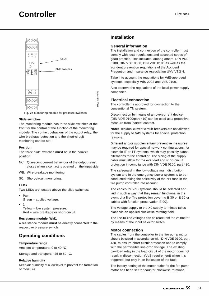
Fig. 27 Monitoring module for pressure switches
Slide switchesThe monitoring module has three slide switches at the front for the control of the function of the monitoring module. The contact behaviour of the output relay, the wire breakage detection and the short-circuit monitoring can be set.
PositionThe three slide switches must be in the correct position:
NC: Quiescent current behaviour of the output relay, closes when a contact is opened on the input side
WB: Wire breakage monitoring
SC: Short-circuit monitoring.
LEDsTwo LEDs are located above the slide switches:
• Pwr:Green = applied voltage.
• 1:Yellow = low system pressure.Red = wire breakage or short-circuit.
Resistance module, WM1A resistance module must be directly connected to the respective pressure switch.
Operating conditionsTemperature rangeAmbient temperature: 0 to 40 °C
Storage and transport: –25 to 60 °C.
Relative humidityKeep air humidity at a low level to prevent the formation of moisture.
Installation
General informationThe installation and connection of the controller must comply with local regulations and accepted codes of good practice. This includes, among others, DIN VDE 0100, DIN VDE 0660, DIN VDE 0106 as well as the accident prevention regulations of the Accident Prevention and Insurance Association UVV VBG 4.
Take into account the regulations for VdS-approved systems, especially VdS 2092 and VdS 2100.
Also observe the regulations of the local power supply companies.
Electrical connectionThe controller is approved for connection to the conventional TN system.
Disconnection by means of an overcurrent device (DIN VDE 0100/part 410) can be used as a protective measure from indirect contact.
Note: Residual current circuit-breakers are not allowed for the supply to VdS systems for special protection reasons.
Different and/or supplementary preventive measures may be required for special network configurations, for example IT or TT systems, which may possibly cause alterations to the controller. The sizing of the supply cable must allow for the overload and short-circuit protection in compliance with DIN VDE 0100, part 430.
The safeguard in the low-voltage main distribution system and in the emergency power system is to be conducted taking the selectivity of the NH-fuse in the fire pump controller into account.
The cables for VdS systems should be selected and laid in such a way that they remain functional in the event of a fire (fire protection covering E 30 or E 90 or cables with function preservation E 90).
The voltage supply to the X0 supply terminals takes place via an applied clockwise rotating field.
The line-to-line voltages can be read from the voltmeter by means of the input selector switch.
Motor connection The cables from the controller to the fire pump motor should be sized in accordance with DIN VDE 0100, part 430, to ensure short-circuit protection and to comply with the permissible line-drop voltage. The existing overload relay in the load circuit of the motor does not result in disconnection (VdS requirement) when it is triggered, but only in an indication of the fault.
The factory setting of the motor outlet for the fire pump motor has been set to "counter-clockwise rotation".
TM03
778
3 49
06
10 11 1298
1
1
4 5 6321
NCNOoffoff
WBSC
Pwr
7LEDs
Slide switches
51

52
Controller Fire NKF
OperationThis section covers the following:
• fire pump• jockey pump (optional)• compressor (optional)• pressure-maintaining pump (optional)• level indication (optional)• motor valve (optional).If the system is in automatic mode during pump start-up, the jockey pump and compressor operate as normal. All additional units are disconnected.
Fire pumpDuring a decrease of pressure in the fire system, the fire pump is switched on automatically via the external pressure switches.
The fire pump can be manually switched on and off by means of the respective buttons.
Jockey pumpThe jockey pump can be operated manually or automatically by using the selector switch.
During automatic operation, the jockey pump is conducted by an external float switch in the pressure tank.
If operation of the compressor is required (due to a decrease of pressure in the pressure tank) and the water level is below the normal level, the jockey pump starts automatically until the normal water level is reached. Subsequently, the nominal pressure is restored using compressed air.
The jockey pump can be manually switched on and off by means of the respective buttons.
CompressorThe compressor can be operated manually or automatically by using the selector switch.
During automatic operation, the compressor is controlled by an external pressure switch, for example connected to the pressure tank.
The compressor can be manually switched on and off by means of the respective buttons.
Pressure-maintaining pumpThe pressure-maintaining pump can be operated manually or automatically by using the selector switch.
During automatic operation, the pressure-maintaining pump is controlled by an external pressure switch.
The pressure-maintaining pump can be manually switched on and off by means of the respective buttons.
Level indicationRod electrodeA 4-pin rod electrode can be used in combination with the appropriate electrode relay for monitoring the level in the pressure tank. The necessary hysteresis between the individual switching points can occur via the individual truncation of electrode pins.
Float switchA float switch can be used to easily monitor the level in the pressure water tank, surge tank, storage tank, etc. in which a hysteresis of 120 mm is sufficient.
Motor valveThe motor valve can be manually closed and opened by means of the respective push buttons.
Technical data
Inputs2 x pressure switches for the fire pump.
OutputsPotential-free signalling contacts for a superordinate fault centre.
Acoustic signal24V DC signal activated in the event of failure.
Optional equipmentDepending on the option selected, two fused outputs are available for the connection of ancillary units.
• 2 x 230 V, 16 A or
• 2 x 400 V, 16 A.
Cabinet material Sheet metalCabinet colour Red, RAL 3000Enclosure class IP 54Rated output 11-250 kWRated current 20.7-435 AMains supply 3 x 400V 50 Hz N PEAmbient temperature 0-40 °C

Controller Fire NKF
Product numbersThe product numbers for WM and WO/M are reference numbers for all controller versions. These numbers only cover controllers with standard operating devices.
Note: Compact Fire NKF units are only available with controllers up to 90 kW.
Product numbers
Versions with monitoring module
Versions without monitoring module
OptionsOptions to be assembled in the controller.
If you order more than three options, a new product number will be created on the order confirmation.
Cabinet dimensionsControllers with and without monitoring module have the same cabinet dimensions. If you choose one or more of the options, the cabinet dimensions may change.
Fig. 28 CONTROL FS 1 control cabinet dimensions
Controller P2[kW] Product No
CONTROL FS 1X 11-15 96158766CONTROL FS 1X 18.5-22 96158767CONTROL FS 1X 30-37 96158768CONTROL FS 1X 45-55 96158769CONTROL FS 1X 75-90 96158770CONTROL FS 1X 110-132 96158771CONTROL FS 1X 133-160 96158772CONTROL FS 1X 161-200 96158773CONTROL FS 1X 201-250 96158774
Controller P2[kW] Product No
CONTROL FS 1X 11-15 96158775CONTROL FS 1X 18.5-22 96158776CONTROL FS 1X 30-37 96158777CONTROL FS 1X 45-55 96158778CONTROL FS 1X 75-90 96158779CONTROL FS 1X 110-132 96158780CONTROL FS 1X 133-160 96158781CONTROL FS 1X 161-200 96158782CONTROL FS 1X 201-250 96158783
Controller Option Product No
CONTROL FS 1.1A Jockey pump, 1.5 kW 96159009CONTROL FS 1.1B Jockey pump, 2.2 kW 96159010CONTROL FS 1.1C Jockey pump, 3-4 kW 96159011CONTROL FS 1.2 Compressor, 2.2-3 kW 96159012CONTROL FS 2.1 Pressure-maintaining pump, 0.75 kW 96739659
CONTROL FS 2.2 Pressure-maintaining pump, 1.1-1.5 kW 96739662
CONTROL FS 2.3 Pressure-maintaining pump, 2.2 kW 96739663CONTROL FS 2.4 Pressure-maintaining pump, 3-4 kW 96159013CONTROL FS 3.1 Level indication, rod electrode 96159014CONTROL FS 3.2 Level indication, float switch 96159015CONTROL FS 4 Motor valve 96159016CONTROL FS 5.1 Fused supply, 400 V 96159017CONTROL FS 5.2 Fused supply, 230 V 96159018
TM03
857
9 20
07
Controller P2[kW]
Dimensions[mm] (HxWxD)
CONTROL FS 1X 11-151000 x 800 x 300
CONTROL FS 1X 18.5-22CONTROL FS 1X 30-37
1200 x 800 x 300CONTROL FS 1X 45-55CONTROL FS 1X 75-90 1400 x 1000 x 300CONTROL FS 1X 110-132 1400 x 1000 x 300CONTROL FS 1X 133-160 1900 x 1000 x 400CONTROL FS 1X 161-200
1900 x 1200 x 400CONTROL FS 1X 201-250
Fire pump
V A
H
WD
53

54

55

www.grundfos.com
96615165 0707 GBRepl. 96615165 0106 Subject to alterations.
Being responsible is our foundationThinking ahead makes it possible
Innovation is the essence
GRUNDFOS A/S . DK-8850 Bjerringbro . DenmarkTelephone: +45 87 50 14 00