Embed Size (px)
Citation preview
GRUNDFOS DATA BOOKLET
Shaft seals
2
Contents
Type designationType designation to EN 12756 3Grundfos type designation 5
Shaft seals in generalWhat is a shaft seal 7How are shaft seals used 7Rotating shaft seals 7Shaft seal components 8Balanced shaft seal 8Unbalanced shaft seal 8Seal balancing 9How does a shaft seal work 11Friction, wear and leakage 12O-ring shaft seals 13Cartridge shaft seals 14
Shaft seals in viscous liquidsShaft seals in viscous liquids 15Recommended shaft seals for viscous liquids 15
Seal face materialsSeal face material combinations 16Tungsten carbide/tungsten carbide 16Silicon carbide/silicon carbide 16Carbon/tungsten carbide or carbon/silicon carbide 17Carbon/ceramic (aluminium oxide) 17Tungsten carbide/hybrid 17Silicon carbide 18
Materials of secondary sealsSecondary seals 22NBR 22EPDM 22FKM 22FFKM 22FXM 23List of pumped liquids 23
Types of shaft sealsTypes of shaft seals 24Grundfos type A 24Grundfos type B 25Grundfos type C 27Grundfos type D 28Grundfos type E 29Grundfos type G 31Grundfos type H 33Grundfos type K 36Grundfos type R 38Seal arrangements 39Double seal (back-to-back) 39Double seal (tandem) 39Cartex-DE shaft seals 40Air-cooled top (for high temperatures) 41Comparing seal types 43
Selection of shaft sealsSelection of the most suitable shaft seal 44
Pumped liquidsLists of pumped liquids 45Acids 46Alkalis 48Salts 49Water 51Coolants 52Fuels 53Synthetic and mineral oils 54Vegetable oils 55Solvents 56Oxidants 57Organic compounds 58Miscellaneous 59
Failure analysisShaft seal failure analysis guide 60
Seal failure analysisKey to failure analysis 61
Further product documentationWebCAPS 62WinCAPS 63
Shaft sealsType designation
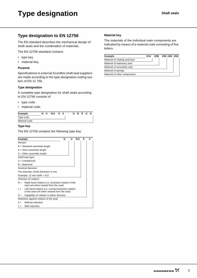
Type designation to EN 12756The EN standard describes the mechanical design of shaft seals and the combination of materials.
The EN 12756 standard contains
• type key• material key.
Purpose
Specifications to external Grundfos shaft seal suppliers are made according to the type designation coding sys-tem of EN 12 756.
Type designation
A complete type designation for shaft seals according to EN 12756 consists of
• type code• material code.
Type key
The EN 12756 contains the following type key:
Material key
The materials of the individual main components are indicated by means of a material code consisting of five letters.
Example N U 012 S 0 - U B E G GType codeMaterial code
Example N U 012 S 0Version:N = Standard assembly lengthK = Short assembly lengthX = Other assembly lengthShaft seal type:U = UnbalancedB = BalancedNominal diameter:The diameter (shaft diameter) in mmExample: 12 mm shaft = 012Direction of rotation:R = Right-hand rotation (i.e. clockwise rotation of the
seal unit when viewed from the seat)L = Left-hand rotation (i.e. counterclockwise rotation
of the seal unit when viewed from the seat)S = Capability of rotation in either directionRetention against rotation of the seat:0 = Without retention1 = With retention
Example (1)U (2)B (3)E (4)G (5)GMaterial of rotating seal faceMaterial of stationary seatMaterial of secondary sealMaterial of springsMaterial of other components
3
4
Type designation Shaft seals
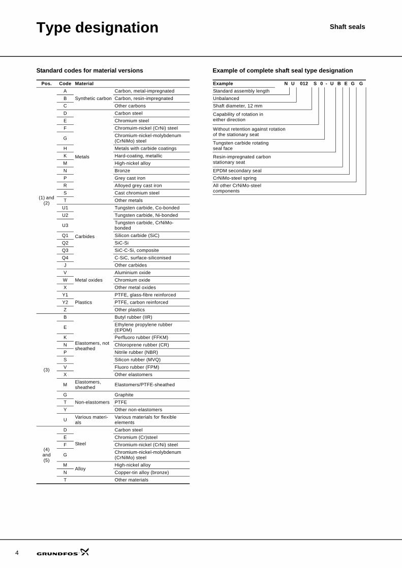
Standard codes for material versions Example of complete shaft seal type designation
Pos. Code Material
(1) and (2)
ASynthetic carbon
Carbon, metal-impregnatedB Carbon, resin-impregnatedC Other carbonsD
Metals
Carbon steelE Chromium steelF Chromuim-nickel (CrNi) steel
G Chromium-nickel-molybdenum (CrNiMo) steel
H Metals with carbide coatingsK Hard-coating, metallicM High-nickel alloyN BronzeP Grey cast ironR Alloyed grey cast ironS Cast chromium steelT Other metals
U1
Carbides
Tungsten carbide, Co-bondedU2 Tungsten carbide, Ni-bonded
U3 Tungsten carbide, CrNiMo-bonded
Q1 Silicon carbide (SiC)Q2 SiC-SiQ3 SiC-C-Si, compositeQ4 C-SiC, surface-siliconisedJ Other carbidesV
Metal oxidesAluminium oxide
W Chromium oxideX Other metal oxides
Y1Plastics
PTFE, glass-fibre reinforcedY2 PTFE, carbon reinforcedZ Other plastics
(3)
B
Elastomers, not sheathed
Butyl rubber (IIR)
E Ethylene propylene rubber (EPDM)
K Perfluoro rubber (FFKM)N Chloroprene rubber (CR)P Nitrile rubber (NBR)S Silicon rubber (MVQ)V Fluoro rubber (FPM)X Other elastomers
M Elastomers, sheathed Elastomers/PTFE-sheathed
GNon-elastomers
GraphiteT PTFEY Other non-elastomers
U Various materi-als
Various materials for flexible elements
(4)and(5)
D
Steel
Carbon steelE Chromium (Cr)steelF Chromium-nickel (CrNi) steel
G Chromium-nickel-molybdenum (CrNiMo) steel
MAlloy
High-nickel alloyN Copper-tin alloy (bronze)T Other materials
Example N U 012 S 0 - U B E G GStandard assembly lengthUnbalancedShaft diameter, 12 mm
Capability of rotation in either direction
Without retention against rotation of the stationary seat
Tungsten carbide rotating seal face
Resin-impregnated carbon stationary seat
EPDM secondary sealCrNiMo-steel springAll other CrNiMo-steel components
Type designation Shaft seals
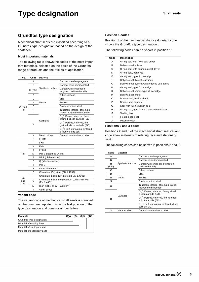
Grundfos type designationMechanical shaft seals are classified according to a Grundfos type designation based on the design of the shaft seal.
Most important materials
The following table shows the codes of the most impor-tant materials, selected on the basis of the Grundfos range of products and their fields of application.
Variant code
The variant code of mechanical shaft seals is stamped on the pump nameplate. It is in the last position of the type designation and consists of four letters.
Position 1 codes
Position 1 of the mechanical shaft seal variant code shows the Grundfos type designation.
The following codes can be shown in position 1:
Positions 2 and 3 codes
Positions 2 and 3 of the mechanical shaft seal variant code show materials of rotating face and stationary seat.
The following codes can be shown in positions 2 and 3:
Pos. Code Material
(1) and (2)
A
Synthetic carbon
Carbon, metal-impregnatedB Carbon, resin-impregnated
H (B/U) Carbon with embedded tungsten carbide (hybrid)
C Other carbonsD
MetalsSteel
N BronzeS Cast chromium steel
U
Carbides
Tungsten carbide, chromium-nickel-molybdenum-bonded
Q
Q1S: Dense, sintered, fine-
grained silicon carbide (SiC)Q1
P: Porous, sintered, fine-grained silicon carbide (SiC)Q1
G: Self-lubricating, sintered silicon carbide (SiC)
V Metal oxides Ceramic (aluminium oxide)
(3)
E EPDMF FXMV FKMK FFKMM PTFE-sheathed O-ringP NBR (nitrile rubber)S Q (silicone rubber)T PTFEX Other elastomers
(4)and(5)
E Chromium (Cr) steel (EN 1.4057)F Chromium-nickel (CrNi) steel ( EN 1.4301)
G Chromium-nickel-molybdenum (CrNiMo) steel (EN 1.4401)
M High-nickel alloy (Hastelloy)T Other alloys
Example (1)A (2)U (3)U (4)EGrundfos type designationMaterial of rotating faceMaterial of stationary seatMaterial of secondary seal
Code DescriptionA O-ring seal with fixed seal driverB Bellows seal, rubberC O-ring seal with spring as seal driverD O-ring seal, balancedE O-ring seal, type A, cartridgeF Bellows seal, type B, cartridgeG Bellows seal, type B, with reduced seal facesH O-ring seal, type D, cartridgeK Bellows seal, metal, type M, cartridgeM Bellows seal, metalO Double seal, back-to-backP Double seal, tandemQ Seal with flush, quench sealR O-ring seal, type A, with reduced seal facesS Stuffing boxT Floating gap sealX Miscellaneous
Code MaterialA
Synthetic carbon
Carbon, metal-impregnatedB Carbon, resin-impregnatedH
(B/U)Carbon with embedded tungsten carbide (hybrid)
C Other carbonsD
MetalsSteel
N BronzeS Cast chromium steel
U
Carbides
Tungsten carbide, chromium-nickel-molybdenum-bonded
Q
Q1S: Dense, sintered, fine-grained
silicon carbide (SiC)Q1
P: Porous, sintered, fine-grained silicon carbide (SiC)Q1
G: Self-lubricating, sintered silicon carbide SiC)
V Metal oxides Ceramic (aluminium oxide)
5
6
Type designation Shaft seals
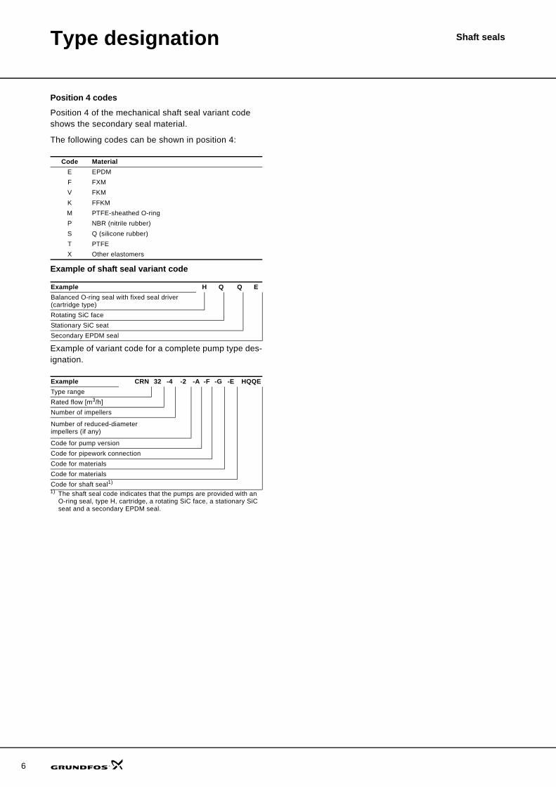
Position 4 codes
Position 4 of the mechanical shaft seal variant code shows the secondary seal material.
The following codes can be shown in position 4:
Example of shaft seal variant code
Example of variant code for a complete pump type des-ignation.
1) The shaft seal code indicates that the pumps are provided with an O-ring seal, type H, cartridge, a rotating SiC face, a stationary SiC seat and a secondary EPDM seal.
Code MaterialE EPDMF FXMV FKMK FFKMM PTFE-sheathed O-ringP NBR (nitrile rubber)S Q (silicone rubber)T PTFEX Other elastomers
Example H Q Q EBalanced O-ring seal with fixed seal driver (cartridge type)Rotating SiC faceStationary SiC seatSecondary EPDM seal
Example CRN 32 -4 -2 -A -F -G -E HQQEType rangeRated flow [m3/h]Number of impellers
Number of reduced-diameter impellers (if any)
Code for pump versionCode for pipework connectionCode for materialsCode for materialsCode for shaft seal1)
Shaft sealsShaft seals in general
What is a shaft sealA shaft seal serves as a barrier in pumps to separate liquids or confine pressure.
How are shaft seals usedShaft seals are used where the pumped liquid can dam-age the motor.
Canned rotor type pumps have no shaft seals which means that the pumped liquid is allowed to enter the motor.
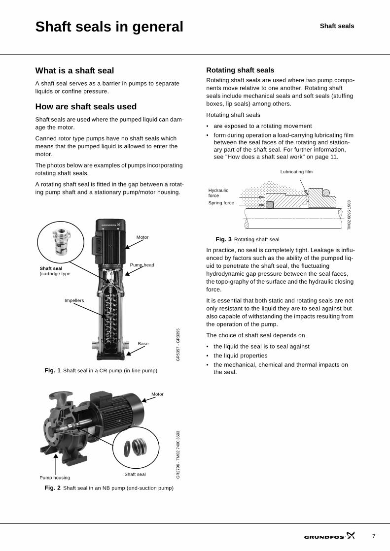
The photos below are examples of pumps incorporating rotating shaft seals.
A rotating shaft seal is fitted in the gap between a rotat-ing pump shaft and a stationary pump/motor housing.
Fig. 1 Shaft seal in a CR pump (in-line pump)
Fig. 2 Shaft seal in an NB pump (end-suction pump)
Rotating shaft sealsRotating shaft seals are used where two pump compo-nents move relative to one another. Rotating shaft seals include mechanical seals and soft seals (stuffing boxes, lip seals) among others.
Rotating shaft seals
• are exposed to a rotating movement• form during operation a load-carrying lubricating film
between the seal faces of the rotating and station-ary part of the shaft seal. For further information, see "How does a shaft seal work" on page 11.
Fig. 3 Rotating shaft seal
In practice, no seal is completely tight. Leakage is influ-enced by factors such as the ability of the pumped liq-uid to penetrate the shaft seal, the fluctuating hydrodynamic gap pressure between the seal faces, the topo-graphy of the surface and the hydraulic closing force.
It is essential that both static and rotating seals are not only resistant to the liquid they are to seal against but also capable of withstanding the impacts resulting from the operation of the pump.
The choice of shaft seal depends on
• the liquid the seal is to seal against• the liquid properties • the mechanical, chemical and thermal impacts on
the seal.
GR
5357
- G
R33
95G
R27
96 -
TM02
740
0 35
03
Motor
Pump head
Base
Shaft seal (cartridge type
Impellers
Motor
Pump housingShaft seal
TM02
689
5 19
03
Hydraulic forceSpring force
Lubricating film
7
8
Shaft seals in general Shaft seals
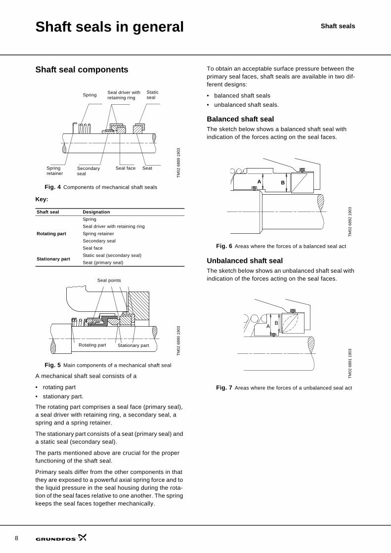
Shaft seal components
Fig. 4 Components of mechanical shaft seals
Key:
Fig. 5 Main components of a mechanical shaft seal
A mechanical shaft seal consists of a
• rotating part• stationary part.
The rotating part comprises a seal face (primary seal), a seal driver with retaining ring, a secondary seal, a spring and a spring retainer.
The stationary part consists of a seat (primary seal) and a static seal (secondary seal).
The parts mentioned above are crucial for the proper functioning of the shaft seal.
Primary seals differ from the other components in that they are exposed to a powerful axial spring force and to the liquid pressure in the seal housing during the rota-tion of the seal faces relative to one another. The spring keeps the seal faces together mechanically.
To obtain an acceptable surface pressure between the primary seal faces, shaft seals are available in two dif-ferent designs:
• balanced shaft seals• unbalanced shaft seals.
Balanced shaft sealThe sketch below shows a balanced shaft seal with indication of the forces acting on the seal faces.
Fig. 6 Areas where the forces of a balanced seal act
Unbalanced shaft sealThe sketch below shows an unbalanced shaft seal with indication of the forces acting on the seal faces.
Fig. 7 Areas where the forces of a unbalanced seal act
TM02
688
9 19
03
Shaft seal Designation
Rotating part
SpringSeal driver with retaining ringSpring retainerSecondary sealSeal face
Stationary partStatic seal (secondary seal)Seat (primary seal)
TM02
689
0 19
03
Spring Static seal
Seal driver with retaining ring
SeatSpring retainer
Seal faceSecondary seal
Rotating part Stationary part
Seal points
TM02
689
2 19
03TM
02 6
891
1903
A B
A B
Shaft seals in general Shaft seals
Seal balancingCalculation formulas
Formula for calculation of the balancing K-factor:
Formula for calculation of the closing force (FC):
Formula for calculation of the opening force (FO):
Formula for calculation of the efficient closing force (FC,eff.):
Formula for calculation of the efficient seat load (Peff.):
Key to symbols:
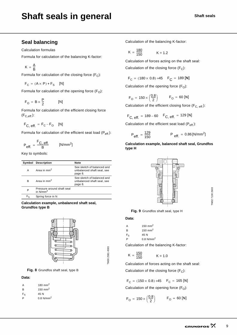
Calculation example, unbalanced shaft seal, Grundfos type B
Fig. 8 Grundfos shaft seal, type B
Data:
Calculation of the balancing K-factor:
Calculation of forces acting on the shaft seal:
Calculation of the closing force (FC):
Calculation of the opening force (FO):
Calculation of the efficient closing force (FC, eff.):
Calculation of the efficient seat load (Peff.):
Calculation example, balanced shaft seal, Grundfos type H
Fig. 9 Grundfos shaft seal, type H
Data:
Calculation of the balancing K-factor:
Calculation of forces acting on the shaft seal:
Calculation of the closing force (FC):
Calculation of the opening force (FO):
Symbol Description Note
A Area in mm2 See sketch of balanced and unbalanced shaft seal, see page 8.
B Area in mm2 See sketch of balanced and unbalanced shaft seal, see page 8.
P Pressure around shaft seal in N/mm2
FS Spring force in N
TM00
258
1 45
93
A 180 mm2
B 150 mm2
FS 45 NP 0.8 N/mm2
K AB----=
FC A P×( ) FS+= [N]
FO B P2----×= [N]
FC, eff. FC FO–= [N]
Peff.FC, eff.
B--------------------= [N/mm2]
TM02
710
0 26
03
A 150 mm2
B 150 mm2
FS 45 NP 0.8 N/mm2
K 180150----------= K = 1.2
FC 180 0.8×( ) 45+= FC 189 [N]=
FO 150 0.82
--------⎝ ⎠⎛ ⎞×= FO 60 [N]=
FC, eff. 189 60–= FC, eff. 129 [N]=
Peff.129150----------= P eff. 0.86= [N/mm2]
K 150150----------= K = 1.0
FC 150 0.8×( ) 45+= FC 165 [N]=
FO 150 0.82
--------⎝ ⎠⎛ ⎞×= FO 60 [N]=
9
10
Shaft seals in general Shaft seals
Calculation of the efficient closing force (FC, eff.):
Calculation of the efficient seat load (Peff.):
Calculation example, balanced shaft seal, Grundfos type K
Data:
Calculation of the balancing K-factor:
Calculation of forces acting on the shaft seal:
Calculation of the closing force (FC):
Calculation of the opening force (FO):
Calculation of the efficient closing force (FC, eff.):
Calculation of the efficient seat load (Peff.):
Depending on the shaft diameter and the material of the stationary seat, unbalanced shaft seals are suitable for applications up to 25 bar. Balanced seals are suitable for applications up to 80 bar by reducing the load of the seal faces. To obtain this reduction, the shaft or bush must have a recess, reducing the external and internal diameter of the rotating seal face. The area affected by the hydraulic pressure in the seal housing is thus reduced without changing the area between the seal faces.
The smaller load on the seal faces causes less gener-ation of heat, and consequently less friction and mechanical wear on the shaft seal. This improves the cost of ownership of the shaft seal.
For balanced shaft seals, the following applies:
A 120 mm2
B 150 mm2
FS 45 NP 0.8 N/mm2
FC, eff. 165 60–= FC, eff. 105 [N]=
Peff.105150----------= P eff. 0.70= [N/mm2]
K 120150----------= K = 0.8
FC 120 0.8×( ) 45+= FC 141 [N]=
FO 150 0.82
--------⎝ ⎠⎛ ⎞×= FO 60 [N]=
FC, eff. 141 60–= FC, eff. 81 [N]=
Peff.81
150----------= Peff. 0.54= [N/mm2]
K AB---- 1 –[ ]≤=
Shaft seals in general Shaft seals
For unbalanced shaft seals, the following applies:
Key to symbols:
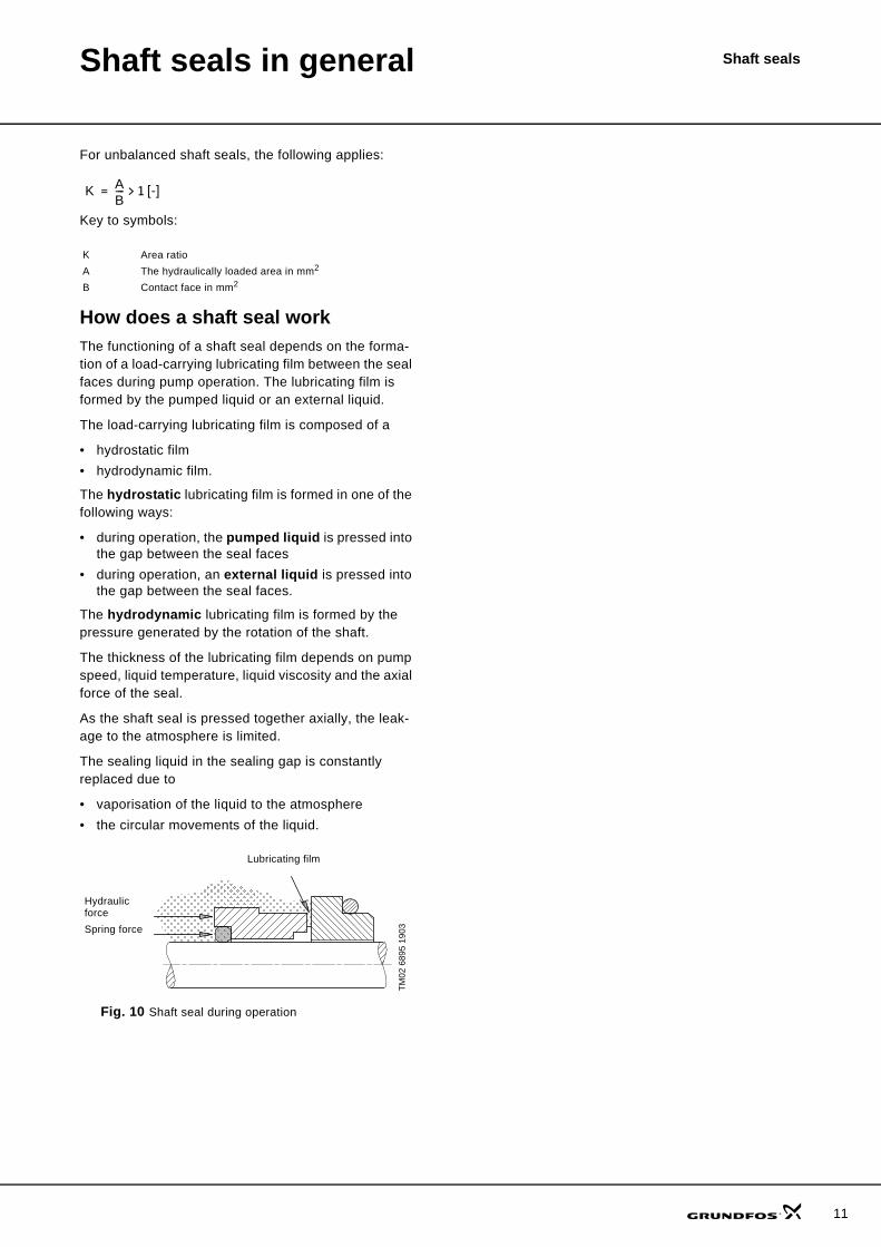
How does a shaft seal workThe functioning of a shaft seal depends on the forma-tion of a load-carrying lubricating film between the seal faces during pump operation. The lubricating film is formed by the pumped liquid or an external liquid.
The load-carrying lubricating film is composed of a
• hydrostatic film• hydrodynamic film.
The hydrostatic lubricating film is formed in one of the following ways:
• during operation, the pumped liquid is pressed into the gap between the seal faces
• during operation, an external liquid is pressed into the gap between the seal faces.
The hydrodynamic lubricating film is formed by the pressure generated by the rotation of the shaft.
The thickness of the lubricating film depends on pump speed, liquid temperature, liquid viscosity and the axial force of the seal.
As the shaft seal is pressed together axially, the leak-age to the atmosphere is limited.
The sealing liquid in the sealing gap is constantly replaced due to
• vaporisation of the liquid to the atmosphere• the circular movements of the liquid.
Fig. 10 Shaft seal during operation
K Area ratioA The hydraulically loaded area in mm2
B Contact face in mm2
TM02
689
5 19
03
K AB---- 1 [-]>=
Hydraulic forceSpring force
Lubricating film
11
12
Shaft seals in general Shaft seals
Friction, wear and leakageThe seal faces of a shaft seal are lubricated by the pumped liquid. Thus, better lubrication means less fric-tion and increased leakage. Conversely, less leakage means worse lubrication conditions and increased fric-tion.
The following factors contribute to the power consump-tion ("power loss") of a shaft seal:
• The centrifugal pumping action of the rotating parts.The power consumption increases dramatically with the speed of rotation (to the third power).
• The seal face friction.Friction between the two seal faces consists of fric-tion in the thin liquid film and friction due to points of contact between the seal faces.
The level of power consumption depends on seal design, lubricating conditions and seal ring materials.
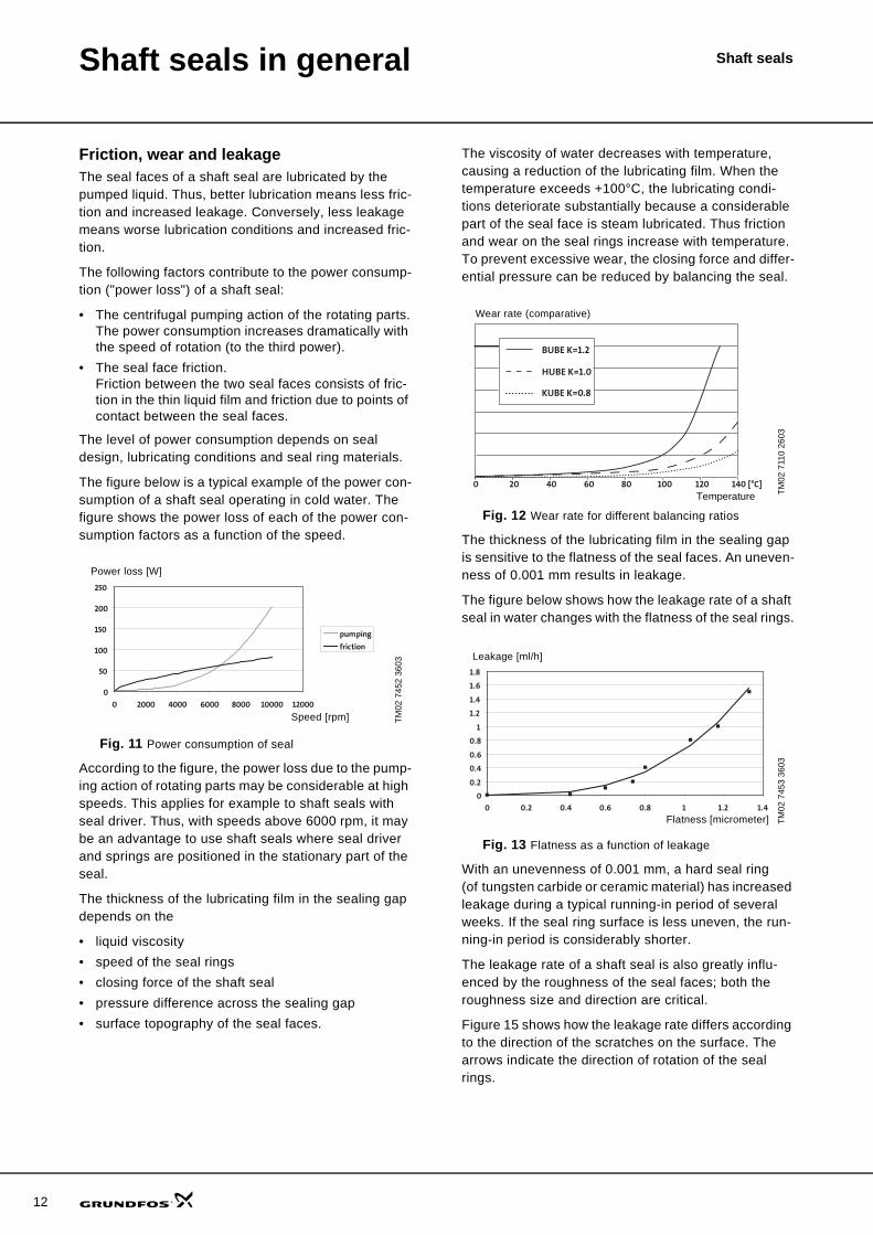
The figure below is a typical example of the power con-sumption of a shaft seal operating in cold water. The figure shows the power loss of each of the power con-sumption factors as a function of the speed.
Fig. 11 Power consumption of seal
According to the figure, the power loss due to the pump-ing action of rotating parts may be considerable at high speeds. This applies for example to shaft seals with seal driver. Thus, with speeds above 6000 rpm, it may be an advantage to use shaft seals where seal driver and springs are positioned in the stationary part of the seal.
The thickness of the lubricating film in the sealing gap depends on the
• liquid viscosity• speed of the seal rings• closing force of the shaft seal• pressure difference across the sealing gap• surface topography of the seal faces.
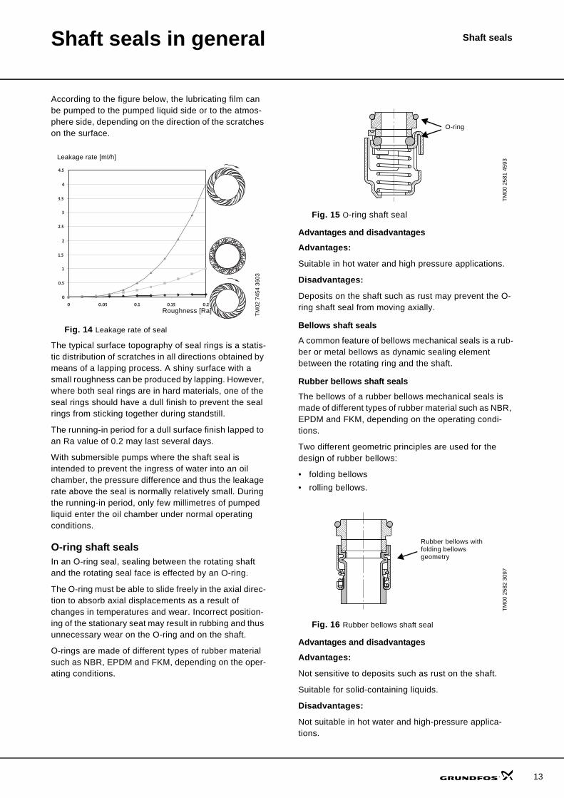
The viscosity of water decreases with temperature, causing a reduction of the lubricating film. When the temperature exceeds +100°C, the lubricating condi-tions deteriorate substantially because a considerable part of the seal face is steam lubricated. Thus friction and wear on the seal rings increase with temperature. To prevent excessive wear, the closing force and differ-ential pressure can be reduced by balancing the seal.
Fig. 12 Wear rate for different balancing ratios
The thickness of the lubricating film in the sealing gap is sensitive to the flatness of the seal faces. An uneven-ness of 0.001 mm results in leakage.
The figure below shows how the leakage rate of a shaft seal in water changes with the flatness of the seal rings.
Fig. 13 Flatness as a function of leakage
With an unevenness of 0.001 mm, a hard seal ring (of tungsten carbide or ceramic material) has increased leakage during a typical running-in period of several weeks. If the seal ring surface is less uneven, the run-ning-in period is considerably shorter.
The leakage rate of a shaft seal is also greatly influ-enced by the roughness of the seal faces; both the roughness size and direction are critical.
Figure 15 shows how the leakage rate differs according to the direction of the scratches on the surface. The arrows indicate the direction of rotation of the seal rings.
TM02
745
2 36
03
0
50
100
150
200
250
0 2000 4000 6000 8000 10000 12000
pumping
friction
Power loss [W]
Speed [rpm]
TM02
711
0 26
03TM
02 7
453
3603
0 20 40 60 80 100 120 140 [°C]
BUBE K=1.2
HUBE K=1.0
KUBE K=0.8
Wear rate (comparative)
Temperature
0
0.2
0.4
0.6
0.8
1
1.2
1.4
1.6
1.8
0 0.2 0.4 0.6 0.8 1 1.2 1.4
Flatness [micrometer]
Leakage [ml/h]
Shaft seals in general Shaft seals
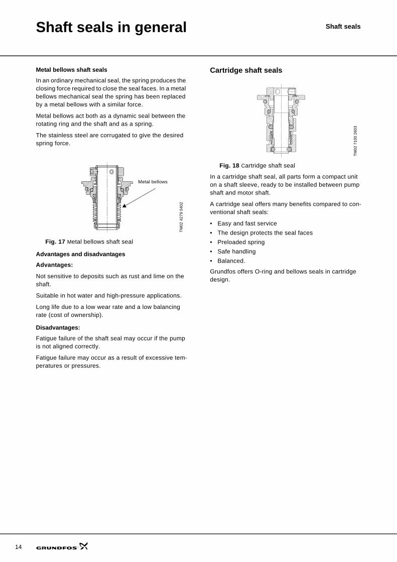
According to the figure below, the lubricating film can be pumped to the pumped liquid side or to the atmos-phere side, depending on the direction of the scratches on the surface.
Fig. 14 Leakage rate of seal
The typical surface topography of seal rings is a statis-tic distribution of scratches in all directions obtained by means of a lapping process. A shiny surface with a small roughness can be produced by lapping. However, where both seal rings are in hard materials, one of the seal rings should have a dull finish to prevent the seal rings from sticking together during standstill.
The running-in period for a dull surface finish lapped to an Ra value of 0.2 may last several days.
With submersible pumps where the shaft seal is intended to prevent the ingress of water into an oil chamber, the pressure difference and thus the leakage rate above the seal is normally relatively small. During the running-in period, only few millimetres of pumped liquid enter the oil chamber under normal operating conditions.
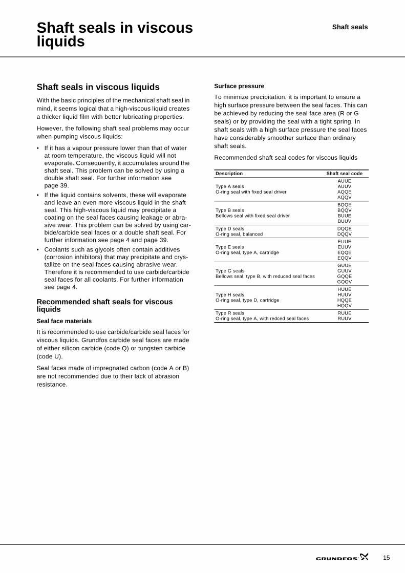
O-ring shaft sealsIn an O-ring seal, sealing between the rotating shaft and the rotating seal face is effected by an O-ring.
The O-ring must be able to slide freely in the axial direc-tion to absorb axial displacements as a result of changes in temperatures and wear. Incorrect position-ing of the stationary seat may result in rubbing and thus unnecessary wear on the O-ring and on the shaft.
O-rings are made of different types of rubber material such as NBR, EPDM and FKM, depending on the oper-ating conditions.
Fig. 15 O-ring shaft seal
Advantages and disadvantages
Advantages:
Suitable in hot water and high pressure applications.
Disadvantages:
Deposits on the shaft such as rust may prevent the O-ring shaft seal from moving axially.
Bellows shaft seals
A common feature of bellows mechanical seals is a rub-ber or metal bellows as dynamic sealing element between the rotating ring and the shaft.
Rubber bellows shaft seals
The bellows of a rubber bellows mechanical seals is made of different types of rubber material such as NBR, EPDM and FKM, depending on the operating condi-tions.
Two different geometric principles are used for the design of rubber bellows:
• folding bellows• rolling bellows.
Fig. 16 Rubber bellows shaft seal
Advantages and disadvantages
Advantages:
Not sensitive to deposits such as rust on the shaft.
Suitable for solid-containing liquids.
Disadvantages:
Not suitable in hot water and high-pressure applica-tions.
TM02
745
4 36
03
0
0.5
1
1.5
2
2.5
3
3.5
4
4.5
0 0.05 0.1 0.15 0.2
Leakage rate [ml/h]
Roughness [Ra]
TM00
258
1 45
93TM
00 2
582
3097
O-ring
Rubber bellows with folding bellows geometry
13
14
Shaft seals in general Shaft seals
Metal bellows shaft seals
In an ordinary mechanical seal, the spring produces the closing force required to close the seal faces. In a metal bellows mechanical seal the spring has been replaced by a metal bellows with a similar force.
Metal bellows act both as a dynamic seal between the rotating ring and the shaft and as a spring.
The stainless steel are corrugated to give the desired spring force.
Fig. 17 Metal bellows shaft seal
Advantages and disadvantages
Advantages:
Not sensitive to deposits such as rust and lime on the shaft.
Suitable in hot water and high-pressure applications.
Long life due to a low wear rate and a low balancing rate (cost of ownership).
Disadvantages:
Fatigue failure of the shaft seal may occur if the pump is not aligned correctly.
Fatigue failure may occur as a result of excessive tem-peratures or pressures.
Cartridge shaft seals
Fig. 18 Cartridge shaft seal
In a cartridge shaft seal, all parts form a compact unit on a shaft sleeve, ready to be installed between pump shaft and motor shaft.
A cartridge seal offers many benefits compared to con-ventional shaft seals:
• Easy and fast service• The design protects the seal faces• Preloaded spring• Safe handling• Balanced.
Grundfos offers O-ring and bellows seals in cartridge design.
TM02
427
9 04
02Metal bellows
TM02
710
0 26
03
15
Shaft sealsShaft seals in viscous liquids
Shaft seals in viscous liquidsWith the basic principles of the mechanical shaft seal in mind, it seems logical that a high-viscous liquid creates a thicker liquid film with better lubricating properties.
However, the following shaft seal problems may occur when pumping viscous liquids:
• If it has a vapour pressure lower than that of water at room temperature, the viscous liquid will not evaporate. Consequently, it accumulates around the shaft seal. This problem can be solved by using a double shaft seal. For further information see page 39.
• If the liquid contains solvents, these will evaporate and leave an even more viscous liquid in the shaft seal. This high-viscous liquid may precipitate a coating on the seal faces causing leakage or abra-sive wear. This problem can be solved by using car-bide/carbide seal faces or a double shaft seal. For further information see page 4 and page 39.
• Coolants such as glycols often contain additives (corrosion inhibitors) that may precipitate and crys-tallize on the seal faces causing abrasive wear. Therefore it is recommended to use carbide/carbide seal faces for all coolants. For further information see page 4.
Recommended shaft seals for viscous liquidsSeal face materials
It is recommended to use carbide/carbide seal faces for viscous liquids. Grundfos carbide seal faces are made of either silicon carbide (code Q) or tungsten carbide (code U).
Seal faces made of impregnated carbon (code A or B) are not recommended due to their lack of abrasion resistance.
Surface pressure
To minimize precipitation, it is important to ensure a high surface pressure between the seal faces. This can be achieved by reducing the seal face area (R or G seals) or by providing the seal with a tight spring. In shaft seals with a high surface pressure the seal faces have considerably smoother surface than ordinary shaft seals.
Recommended shaft seal codes for viscous liquids
Description Shaft seal code
Type A sealsO-ring seal with fixed seal driver
AUUEAUUVAQQEAQQV
Type B sealsBellows seal with fixed seal driver
BQQEBQQVBUUEBUUV
Type D sealsO-ring seal, balanced
DQQEDQQV
Type E sealsO-ring seal, type A, cartridge
EUUEEUUVEQQEEQQV
Type G sealsBellows seal, type B, with reduced seal faces
GUUEGUUVGQQEGQQV
Type H sealsO-ring seal, type D, cartridge
HUUEHUUVHQQEHQQV
Type R sealsO-ring seal, type A, with redced seal faces
RUUERUUV
16
Shaft sealsSeal face materials
Seal face material combinationsThe choice of seal face materials is decisive of the func-tion and life of the mechanical shaft seal. Below is a description of the possible material combinations.
Noise is generated as a result of the poor lubricating conditions in seals in connection with low-viscosity liq-uids. The viscosity of water decreases with increasing temperature. This means that the lubricating conditions are deteriorated with increasing temperature. A speed reduction has the same effect.
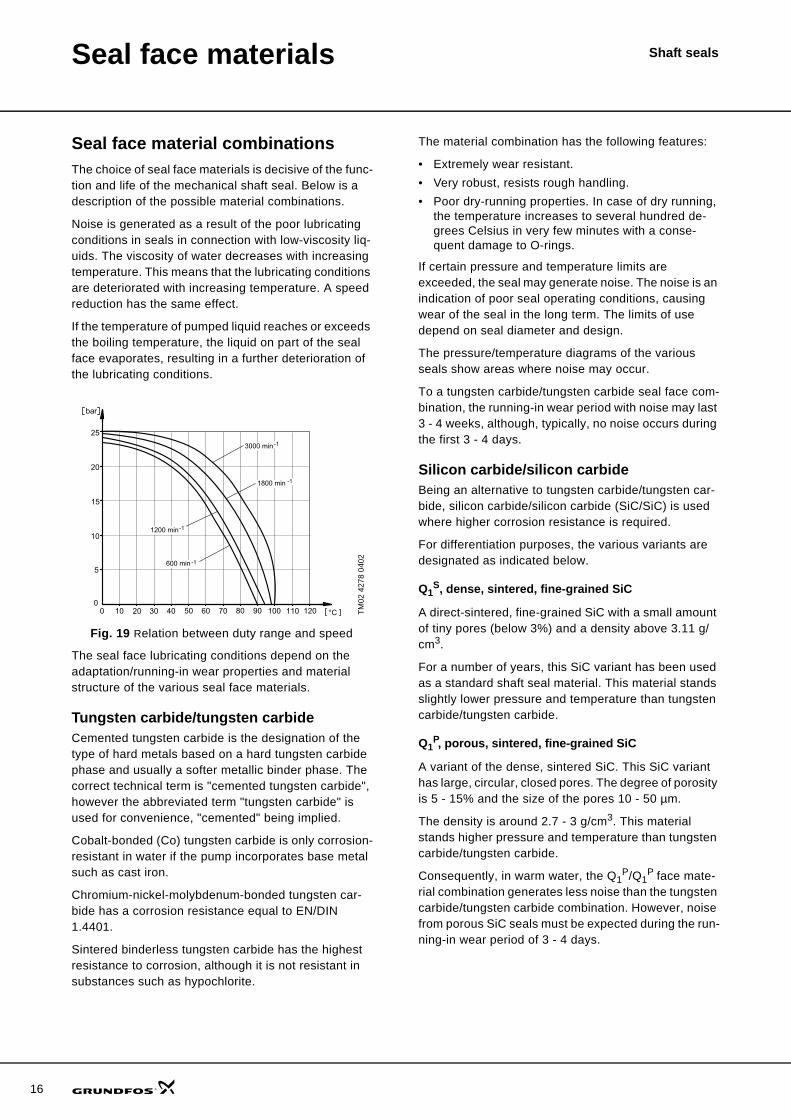
If the temperature of pumped liquid reaches or exceeds the boiling temperature, the liquid on part of the seal face evaporates, resulting in a further deterioration of the lubricating conditions.
Fig. 19 Relation between duty range and speed
The seal face lubricating conditions depend on the adaptation/running-in wear properties and material structure of the various seal face materials.
Tungsten carbide/tungsten carbide Cemented tungsten carbide is the designation of the type of hard metals based on a hard tungsten carbide phase and usually a softer metallic binder phase. The correct technical term is "cemented tungsten carbide", however the abbreviated term "tungsten carbide" is used for convenience, "cemented" being implied.
Cobalt-bonded (Co) tungsten carbide is only corrosion-resistant in water if the pump incorporates base metal such as cast iron.
Chromium-nickel-molybdenum-bonded tungsten car-bide has a corrosion resistance equal to EN/DIN 1.4401.
Sintered binderless tungsten carbide has the highest resistance to corrosion, although it is not resistant in substances such as hypochlorite.
The material combination has the following features:
• Extremely wear resistant.• Very robust, resists rough handling.• Poor dry-running properties. In case of dry running,
the temperature increases to several hundred de-grees Celsius in very few minutes with a conse-quent damage to O-rings.
If certain pressure and temperature limits are exceeded, the seal may generate noise. The noise is an indication of poor seal operating conditions, causing wear of the seal in the long term. The limits of use depend on seal diameter and design.
The pressure/temperature diagrams of the various seals show areas where noise may occur.
To a tungsten carbide/tungsten carbide seal face com-bination, the running-in wear period with noise may last 3 - 4 weeks, although, typically, no noise occurs during the first 3 - 4 days.
Silicon carbide/silicon carbideBeing an alternative to tungsten carbide/tungsten car-bide, silicon carbide/silicon carbide (SiC/SiC) is used where higher corrosion resistance is required.
For differentiation purposes, the various variants are designated as indicated below.
Q1S, dense, sintered, fine-grained SiC
A direct-sintered, fine-grained SiC with a small amount of tiny pores (below 3%) and a density above 3.11 g/cm3.
For a number of years, this SiC variant has been used as a standard shaft seal material. This material stands slightly lower pressure and temperature than tungsten carbide/tungsten carbide.
Q1P, porous, sintered, fine-grained SiC
A variant of the dense, sintered SiC. This SiC variant has large, circular, closed pores. The degree of porosity is 5 - 15% and the size of the pores 10 - 50 µm.
The density is around 2.7 - 3 g/cm3. This material stands higher pressure and temperature than tungsten carbide/tungsten carbide.
Consequently, in warm water, the Q1P/Q1
P face mate-rial combination generates less noise than the tungsten carbide/tungsten carbide combination. However, noise from porous SiC seals must be expected during the run-ning-in wear period of 3 - 4 days.
TM02
427
8 04
02
Seal face materials Shaft seals
Q1G, self-lubricating, sintered SiC
Several variants of SiC materials containing dry lubri-cants are available on the market. In this document, the designation Q1
G applies to a SiC material which is suit-able for use in distilled or demineralized water, as opposed to the above materials.
Q1G/Q1
G stands the same pressure and temperature as Q1
P/Q1P.
The dry lubricants, i.e. graphite, reduce the friction in case of dry running, which is of decisive importance to the durability of a seal during dry running.
SiC/SiC features
The SiC/SiC material combination has the following features:
• Very brittle material requiring careful handling.• Extremely wear-resistant.• Extremely good corrosion resistance. SiC (Q1
S, Q1P
and Q1G) hardly corrodes, irrespective of the
pumped liquid type. However, an exception is water with very poor conductivity, such as demineralized water, which attacks the SiC variants Q1
S and Q1P
whereas Q1G is corrosion-resistant also in this liq-
uid.• In general, the material combinations have poor dry-
running properties (like tungsten carbide/tungsten carbide), however, the Q1
G/Q1G material withstands
a limited period of dry running because of the graphite content of the material.
Carbon/tungsten carbide or carbon/silicon carbideSeals with one carbon seal face have the following fea-tures:
• Brittle material requiring careful handling. • Worn by liquids containing solid particles. • Good corrosion resistance.• Good dry-running properties (temporary dry run-
ning).• The self-lubricating properties of carbon make the
seal suitable for use even with poor lubricating con-ditions (high temperatures) without generating noise. However, such conditions will cause wear of the carbon seal face leading to reduced seal life. The wear depends on the pressure, temperature, liquid, diameter and seal design. Low speeds reduce the lubrication between the seal faces; as a result, increased wear might have been expected. However, this is normally not the case be-cause the distance that the seal faces have to move is reduced.
• Metal-impregnated carbon (A) offers limited corro-sion resistance, but improved mechanical strength, heat conductivity and thus reduced wear.
• With reduced mechanical strength, but higher corro-sion resistance, synthetic resin-impregnated car-bon (B) covers a wide application field. Synthetic resin-impregnated carbon is approved for potable applications.
• The use of carbon/SiC for hot-water applications may cause heavy wear on the SiC, depending on the quality of the carbon and water.This type of wear primarily applies to Q1
S/carbon. The use of Q1
P, Q1G or a carbon/tungsten carbide
combination causes far less wear. Thus, carbon/tungsten carbide, carbon/Q1
P or carbon/Q1G are
recommended for hot water systems.
Carbon/ceramic (aluminium oxide)Good all-round seal for not too demanding applications. The seal has the following features:
• Brittle material requiring careful handling.• Worn by liquids containing solid particles.• Limited corrosion resistance, 5 < pH < 9, depending
on ceramic type.• Relatively good dry-running properties. However,
thermal cracks may occur in case of a sudden influx of water to a hot seal after a period of dry running or similar condition.
• The carbon of the seal offers properties very similar to the carbon/tungsten carbide seal. However, com-pared to the carbon/tungsten carbide seal, the pres-sure and temperature ranges are limited.
Tungsten carbide/hybridCombining the positive properties of the tungsten car-bide/tungsten carbide and carbon/tungsten carbide seal face combinations, the tungsten carbide/hybrid combination has the following features:
• Extremely wear-resistant.• Resistant to rough handling.• Certain dry-running properties (temporary dry run-
ning).• Corrosion resistance equal to EN 1.4401, corre-
sponding to the resistance of a CRN pump. In cer-tain corrosive liquids and solvents, the resistance is restricted.
• Application limits as to pressure and temperature are similar to tungsten carbide/tungsten carbide due to the risk of seizure. However, exceeding the limits may damage the hybrid.
Some of the additives used in anti-freeze liquids on gly-col basis may cause precipitation, especially at high temperatures. In such cases, tungsten carbide/tung-sten carbide should be used, if possible.
17
18
Seal face materials Shaft seals
Silicon carbideThe ceramic silicon carbide (SiC) has been manufac-tured for many years.
There are three main types of SiC:
• Reaction-bonded and liquid-phase sintered grades have limited corrosion resistance in alkaline water due to the content of free silicon.
• Converted carbon is produced from carbon graphite and can also be made as a thin SiC layer on the surface of the carbon.
• The most common SiC for seal rings are direct-sin-tered silicon carbide.
Direct-sintered SiC
The direct-sintered SiC has a typical porosity below 2%, but also grades with pores have been developed. These pores are discrete, non-interconnected and dis-persed in a controlled manner throughout the body of the material. The spherical pores act as fluid or lubri-cant reservoirs helping to promote the retention of a fluid film at the interface of sliding component surfaces. This pore-based lubrication mechanism allows porous SiC to outperform conventional reaction-bonded and sintered silicon carbides in hot water.
Extended sintering or adding different fillers can imply variations in these standard SiC grades. Fillers can be added to obtain better electric conductivity, more toughness or lower friction.
Carbon or graphite inclusions can be used as dry lubri-cant to reduce friction. Low friction of graphite can only be achieved with appropriate impurities because the intrinsic friction of graphite is high. For graphite to suc-cessfully act as a lubricant, the bonding between the SiC and the graphite as well as the size and amount of the graphite inclusions must be optimized. In a working seal the graphite must be smeared out in the seal face to reduce friction, and it must be possible to remove some of the graphite from the inclusions.
Performance of seals with different SiC variants
Evaluation of materials for seal faces requires thorough testing at many different testing conditions.
SiC seal materials can be subjected to the following tests:
• Performance in hot water applications• Dry running• Water containing abrasive particles• Water containing glycol• Demineralized water• Seizure test.
The tests are described in detail as from page 19.
During the last 15 years almost 50 different SiC grades have been tested at Grundfos and categorized in groups according to performance.
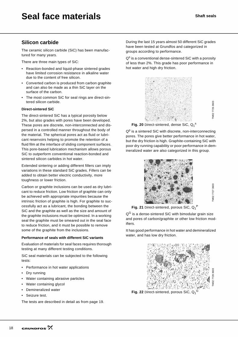
Qs is a conventional dense-sintered SiC with a porosity of less than 2%. This grade has poor performance in hot water and high dry friction.
Fig. 20 Direct-sintered, dense SiC, Q1s
Qp is a sintered SiC with discrete, non-interconnecting pores. The pores give better performance in hot water, but the dry friction is high. Graphite-containing SiC with poor dry running capability or poor performance in dem-ineralized water are also categorized in this group.
Fig. 21 Direct-sintered, porous SiC, Q1P
QG is a dense-sintered SiC with bimodular grain size and pores of carbon/graphite or other low friction mod-ifiers.
It has good performance in hot water and demineralized water, and has low dry friction.
Fig. 22 Direct-sintered, porous SiC, Q1G
TM02
772
6 36
03TM
02 7
727
3603
TM02
772
8 36
03
Seal face materials Shaft seals
Performance in hot water
The lubrication of the seal faces in hot water is scarce due to the low viscosity of water at high temperatures and evaporation in the seal gap.
Limits of temperature and pressure ranges are based on tests where factors such as friction, torque and leak-age are measured.
Above these limits noise from the seals may be expected and fatique wear may occur.
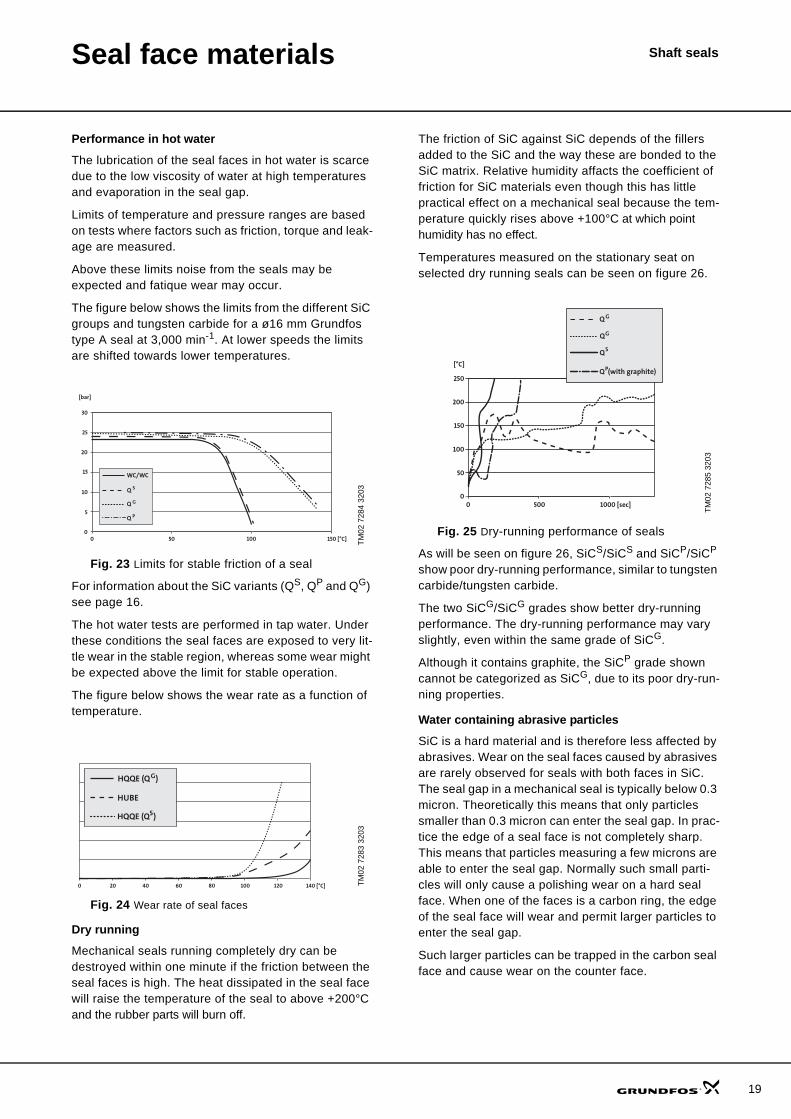
The figure below shows the limits from the different SiC groups and tungsten carbide for a ø16 mm Grundfos type A seal at 3,000 min-1. At lower speeds the limits are shifted towards lower temperatures.
Fig. 23 Limits for stable friction of a seal
For information about the SiC variants (QS, QP and QG) see page 16.
The hot water tests are performed in tap water. Under these conditions the seal faces are exposed to very lit-tle wear in the stable region, whereas some wear might be expected above the limit for stable operation.
The figure below shows the wear rate as a function of temperature.
Fig. 24 Wear rate of seal faces
Dry running
Mechanical seals running completely dry can be destroyed within one minute if the friction between the seal faces is high. The heat dissipated in the seal face will raise the temperature of the seal to above +200°C and the rubber parts will burn off.
The friction of SiC against SiC depends of the fillers added to the SiC and the way these are bonded to the SiC matrix. Relative humidity affacts the coefficient of friction for SiC materials even though this has little practical effect on a mechanical seal because the tem-perature quickly rises above +100°C at which point humidity has no effect.
Temperatures measured on the stationary seat on selected dry running seals can be seen on figure 26.
Fig. 25 Dry-running performance of seals
As will be seen on figure 26, SiCS/SiCS and SiCP/SiCP show poor dry-running performance, similar to tungsten carbide/tungsten carbide.
The two SiCG/SiCG grades show better dry-running performance. The dry-running performance may vary slightly, even within the same grade of SiCG.
Although it contains graphite, the SiCP grade shown cannot be categorized as SiCG, due to its poor dry-run-ning properties.
Water containing abrasive particles
SiC is a hard material and is therefore less affected by abrasives. Wear on the seal faces caused by abrasives are rarely observed for seals with both faces in SiC. The seal gap in a mechanical seal is typically below 0.3 micron. Theoretically this means that only particles smaller than 0.3 micron can enter the seal gap. In prac-tice the edge of a seal face is not completely sharp. This means that particles measuring a few microns are able to enter the seal gap. Normally such small parti-cles will only cause a polishing wear on a hard seal face. When one of the faces is a carbon ring, the edge of the seal face will wear and permit larger particles to enter the seal gap.
Such larger particles can be trapped in the carbon seal face and cause wear on the counter face.
TM02
728
4 32
03TM
02 7
283
3203
0 50 100 150 [°C]0
5
10
15
20
25
30
[bar]
Q
Q P
Q
WC/WC
S
G
0 20 40 60 80 100 120 140 [°C]
HQQE (Q )
HQQE (Q ) G
HUBE
S
TM02
728
5 32
03
0 500 1000 [sec]0
50
100
150
200
250
[°C]Q (with graphite)P
Q G
QG
QS
19
20
Seal face materials Shaft seals
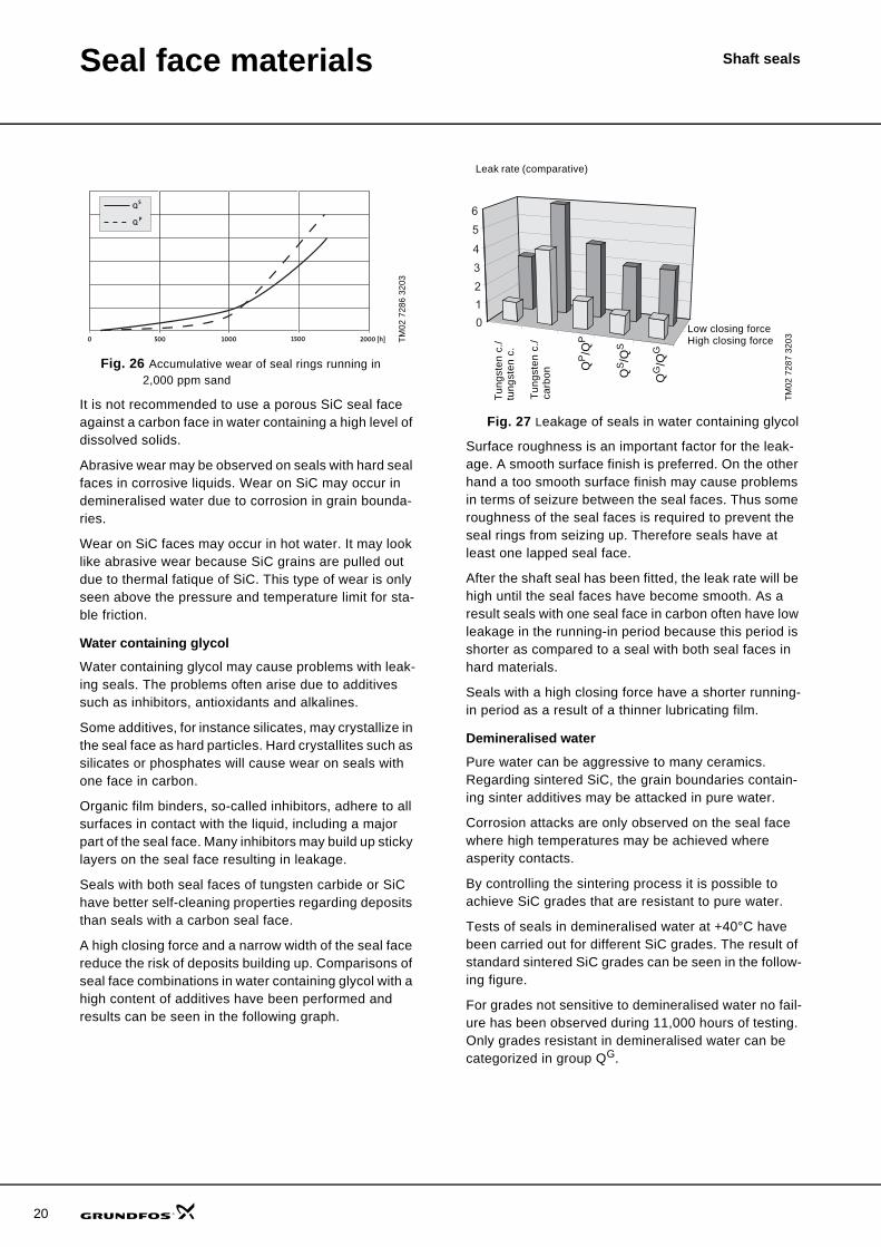
Fig. 26 Accumulative wear of seal rings running in 2,000 ppm sand
It is not recommended to use a porous SiC seal face against a carbon face in water containing a high level of dissolved solids.
Abrasive wear may be observed on seals with hard seal faces in corrosive liquids. Wear on SiC may occur in demineralised water due to corrosion in grain bounda-ries.
Wear on SiC faces may occur in hot water. It may look like abrasive wear because SiC grains are pulled out due to thermal fatique of SiC. This type of wear is only seen above the pressure and temperature limit for sta-ble friction.
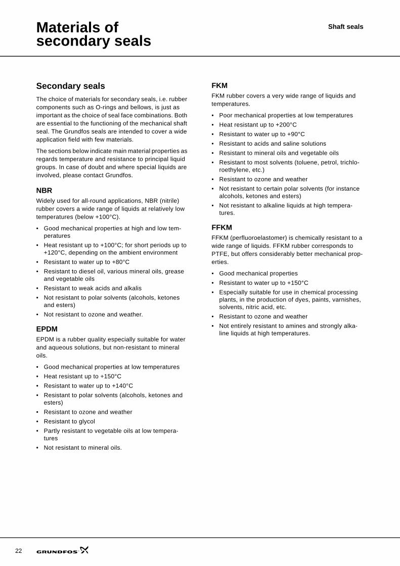
Water containing glycol
Water containing glycol may cause problems with leak-ing seals. The problems often arise due to additives such as inhibitors, antioxidants and alkalines.
Some additives, for instance silicates, may crystallize in the seal face as hard particles. Hard crystallites such as silicates or phosphates will cause wear on seals with one face in carbon.
Organic film binders, so-called inhibitors, adhere to all surfaces in contact with the liquid, including a major part of the seal face. Many inhibitors may build up sticky layers on the seal face resulting in leakage.
Seals with both seal faces of tungsten carbide or SiC have better self-cleaning properties regarding deposits than seals with a carbon seal face.
A high closing force and a narrow width of the seal face reduce the risk of deposits building up. Comparisons of seal face combinations in water containing glycol with a high content of additives have been performed and results can be seen in the following graph.
Fig. 27 Leakage of seals in water containing glycol
Surface roughness is an important factor for the leak-age. A smooth surface finish is preferred. On the other hand a too smooth surface finish may cause problems in terms of seizure between the seal faces. Thus some roughness of the seal faces is required to prevent the seal rings from seizing up. Therefore seals have at least one lapped seal face.
After the shaft seal has been fitted, the leak rate will be high until the seal faces have become smooth. As a result seals with one seal face in carbon often have low leakage in the running-in period because this period is shorter as compared to a seal with both seal faces in hard materials.
Seals with a high closing force have a shorter running-in period as a result of a thinner lubricating film.
Demineralised water
Pure water can be aggressive to many ceramics. Regarding sintered SiC, the grain boundaries contain-ing sinter additives may be attacked in pure water.
Corrosion attacks are only observed on the seal face where high temperatures may be achieved where asperity contacts.
By controlling the sintering process it is possible to achieve SiC grades that are resistant to pure water.
Tests of seals in demineralised water at +40°C have been carried out for different SiC grades. The result of standard sintered SiC grades can be seen in the follow-ing figure.
For grades not sensitive to demineralised water no fail-ure has been observed during 11,000 hours of testing. Only grades resistant in demineralised water can be categorized in group QG.
TM02
728
6 32
03
0 500 1000 2000 [h]1500
Q
Q
S
P
TM02
728
7 32
03
0
1
2
3
4
5
6
QP/Q
P
QS/Q
S
QG
/QG
Low closing forceHigh closing force
Leak rate (comparative)
Tung
sten
c./
tung
sten
c.
Tung
sten
c./
carb
on

Seal face materials Shaft seals
Fig. 28 Failure of SiC seals in demineralised water
Seizure of seal faces caused by storing
Very smooth and flat seal faces will easily adhere to each other. In extreme situations the adhesion becomes so strong that the shaft on the motor of the pump cannot rotate.
There are different mechanisms acting on the adhesion between the seal faces.
Physical adhesion
Vacuum may occur when two flat and smooth surfaces are pressed tightly together.
The force created by the vacuum is axial, meaning that the force needed to separate the two surfaces has to be large whereas the shear force needed to rotate the sur-faces is lower. The size of the shear force at start-up is the same as the force needed for a very low rotational speed. The coefficient of friction at low rotational speed for different surface combinations can be seen on the graph below.
Start friction in water
Fig. 29 Start friction in water
Chemical adhesion of surfaces
All surfaces subjected to the atmosphere have an oxide layer. The equilibrium of the oxide layer may change when the surface is in close contact with another sur-face or when it is exposed to the pumped liquid. This change in equilibrium may involve chemical bindings to oxides from other surfaces. The more inert the oxide layer is to the surroundings, the weaker will the bind-ings to the counter surface be. If the liquid is aggressive to the seal face material, the seal faces may corrode together and create immensely high adhesion forces.
To prevent such adhesion mechanisms, highly inert dissimilar materials of the seal faces are preferred.
Chemical adhesion involving adhesive agents
If the pumped liquid contains ions that may precipitate on the seal face, these precipitations may act as glue between the seal faces.
This adhesion mechanism may occur in hard water and can be reduced by having one seal face in carbon. Also hard materials containing solid lubricants will reduce adhesion because the dry lubricant will be smeared out as a thin layer on the seal face, providing low shear forces.
Conclusion
The sensitivity to abrasive particles is low when using hard materials in both seal rings such as SiC against SiC.
Friction of SiC against SiC in hot water are reduced by the porosities in the seal face material. Generally, the resistivity to corrosion of sintered SiC is good except in pure water, but with SiC containing long grains also resistance against pure water can be obtained.
Incorporating small pockets filled with solid lubricants can reduce dry friction of SiC.
Mechanical seals with improved SiC grades QG are thus able to handle many different applications, thereby increasing the reliability of the pump.
TM02
728
8 32
03TM
02 7
289
3203
0
10
20
30
40
50
60
70
80
90
100
0 2000 4000 6000 8000 10000 12000
Failures [%]
[hour]
0 50 100 150 [°C]0
0.1
0.2
0.3
0.4
0.5
0.6
TC/SiC
TC/Carbon
TC/TC
SiC-G/SiC-G
[°C]
Coefficient of friction
21
22
Shaft sealsMaterials of secondary seals
Secondary sealsThe choice of materials for secondary seals, i.e. rubber components such as O-rings and bellows, is just as important as the choice of seal face combinations. Both are essential to the functioning of the mechanical shaft seal. The Grundfos seals are intended to cover a wide application field with few materials.
The sections below indicate main material properties as regards temperature and resistance to principal liquid groups. In case of doubt and where special liquids are involved, please contact Grundfos.
NBRWidely used for all-round applications, NBR (nitrile) rubber covers a wide range of liquids at relatively low temperatures (below +100°C).
• Good mechanical properties at high and low tem-peratures
• Heat resistant up to +100°C; for short periods up to +120°C, depending on the ambient environment
• Resistant to water up to +80°C • Resistant to diesel oil, various mineral oils, grease
and vegetable oils• Resistant to weak acids and alkalis• Not resistant to polar solvents (alcohols, ketones
and esters)• Not resistant to ozone and weather.
EPDMEPDM is a rubber quality especially suitable for water and aqueous solutions, but non-resistant to mineral oils.
• Good mechanical properties at low temperatures• Heat resistant up to +150°C • Resistant to water up to +140°C• Resistant to polar solvents (alcohols, ketones and
esters) • Resistant to ozone and weather• Resistant to glycol• Partly resistant to vegetable oils at low tempera-
tures • Not resistant to mineral oils.
FKM FKM rubber covers a very wide range of liquids and temperatures.
• Poor mechanical properties at low temperatures• Heat resistant up to +200°C• Resistant to water up to +90°C • Resistant to acids and saline solutions • Resistant to mineral oils and vegetable oils • Resistant to most solvents (toluene, petrol, trichlo-
roethylene, etc.)• Resistant to ozone and weather • Not resistant to certain polar solvents (for instance
alcohols, ketones and esters)• Not resistant to alkaline liquids at high tempera-
tures.
FFKMFFKM (perfluoroelastomer) is chemically resistant to a wide range of liquids. FFKM rubber corresponds to PTFE, but offers considerably better mechanical prop-erties.
• Good mechanical properties• Resistant to water up to +150°C • Especially suitable for use in chemical processing
plants, in the production of dyes, paints, varnishes, solvents, nitric acid, etc.
• Resistant to ozone and weather • Not entirely resistant to amines and strongly alka-
line liquids at high temperatures.
Materials of secondary seals
Shaft seals
FXMFXM (fluorinated copolymer) is particularly suitable for extremely high temperatures and pressures as well as for use in acid liquids and gasses within oil and gas extraction (in boreholes, on land and at sea). Its resist-ance to chemicals and high temperatures has been considerably improved as compared to fluorized rub-ber, with excellent resistance to hot water and steam.
• Elastic seal material• Temperature range: –10°C to +275°C; for short peri-
ods up to +300°C• Excellent hot water and steam resistance• Available in material resistant to sudden decom-
pression.
Consisting of a modified structure of tetrafluoroethylene (TFE) and propylene copolymers, FXM is widely used within
• the chemical and petrochemical industry• the aviation and space industry• mechanical engineering• refineries.
List of pumped liquidsThe table below shows the resistance of the secondary seal rubber materials to low and high temperatures and to a selection of pumped liquids.
Based on water.
Legend
A number of typical pumped liquids are listed below.
The table below shows the resistance of the secondary seal rubber materials to low and high temperatures and to a selection of pumped liquids.
Factors NBR EPDM FKM FFKM FXMLow temperatures (temp. < 0°C) + + – – –High temperatures(temp. > +90°C) – + – + +
Acids ± ± ± + ±
Alkalis + + – + +
Glycols + + + +
Oils and fuels ± – + + ±
Solvents – – ± + –
Symbol Meaning+ Suitable± Suitable under certain conditions- Not suitable
Pumped liquid Chemical formula Description
Acids(pH < 7)
Sulphuric acid H2SO4 Inorganic acidHydrochloric acid HCl Inorganic acidPhosphoric acid H3PO4 Inorganic acidNitric acid HNO3 Inorganic acidChromic acid CrO3 Inorganic acidAcetic acid CH3COOH Organic acidFormic acid HCOOH Organic acid
Alkalis(pH > 7)
Sodium hydroxide NaOHPotassium hydroxide KOHCalcium hydroxide CaOHAmmonium hydroxide NH4OH
CoolantsPropylene glycol CH2OHCHOHCH3Ethylene glycol C2H4(OH)2Glycerine CH2OHCH2OH
Fuels and oils
Petrol Mineral oilDiesel oil Mineral oilOlive oil Vegetable oil
SolventsXylene C6H4(CH3)2Trichloroethylene C2HCl3Benzene C6H6
23
24
Shaft sealsTypes of shaft seals
Types of shaft sealsThe following pages give a short description of some of Grundfos’ mechanical shaft seal types, including their application profiles.
Due to the wear on carbon seal faces, the description of carbon shaft seal types includes a table indicating service intervals.
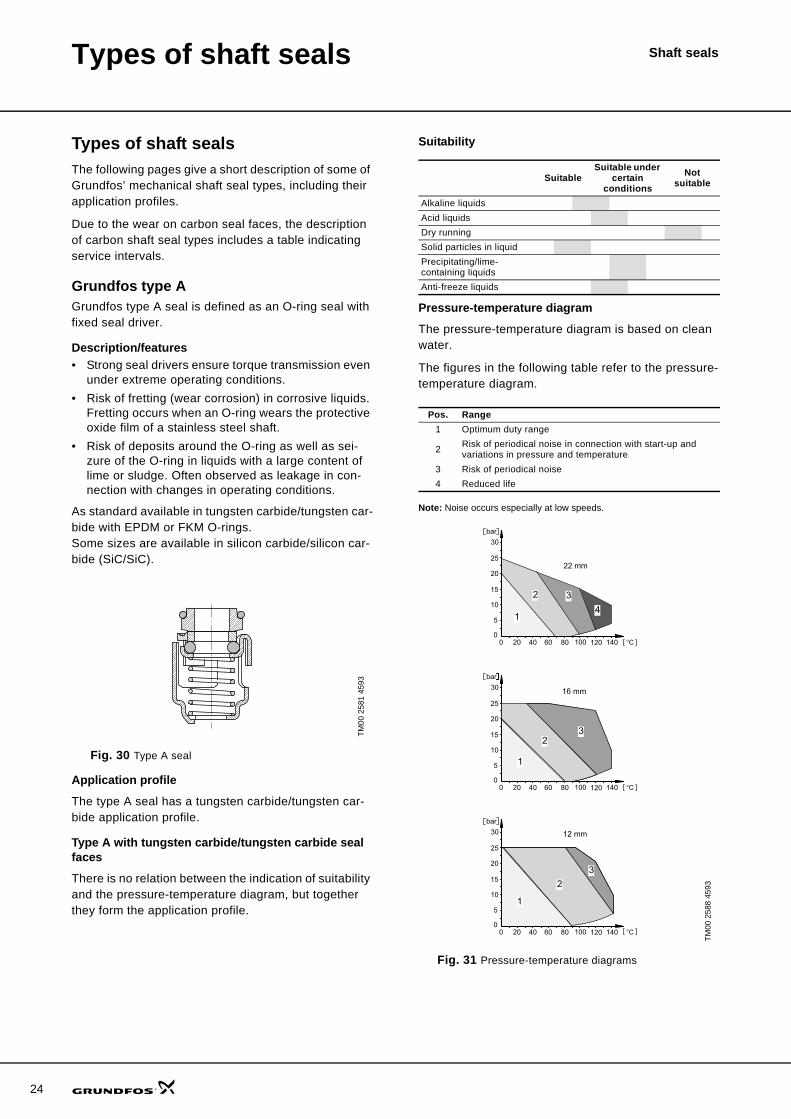
Grundfos type AGrundfos type A seal is defined as an O-ring seal with fixed seal driver.
Description/features• Strong seal drivers ensure torque transmission even
under extreme operating conditions.• Risk of fretting (wear corrosion) in corrosive liquids.
Fretting occurs when an O-ring wears the protective oxide film of a stainless steel shaft.
• Risk of deposits around the O-ring as well as sei-zure of the O-ring in liquids with a large content of lime or sludge. Often observed as leakage in con-nection with changes in operating conditions.
As standard available in tungsten carbide/tungsten car-bide with EPDM or FKM O-rings.Some sizes are available in silicon carbide/silicon car-bide (SiC/SiC).
Fig. 30 Type A seal
Application profile
The type A seal has a tungsten carbide/tungsten car-bide application profile.
Type A with tungsten carbide/tungsten carbide seal faces
There is no relation between the indication of suitability and the pressure-temperature diagram, but together they form the application profile.
Suitability
Pressure-temperature diagram
The pressure-temperature diagram is based on clean water.
The figures in the following table refer to the pressure-temperature diagram.
Note: Noise occurs especially at low speeds.
Fig. 31 Pressure-temperature diagrams
TM00
258
1 45
93
SuitableSuitable under
certain conditions
Not suitable
Alkaline liquidsAcid liquidsDry runningSolid particles in liquidPrecipitating/lime-containing liquidsAnti-freeze liquids
Pos. Range1 Optimum duty range
2 Risk of periodical noise in connection with start-up and variations in pressure and temperature
3 Risk of periodical noise4 Reduced life
TM00
258
8 45
93
Types of shaft seals Shaft seals
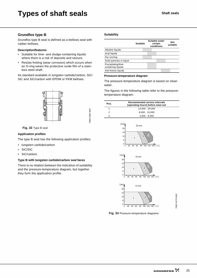
Grundfos type BGrundfos type B seal is defined as a bellows seal with rubber bellows.
Description/features• Suitable for lime- and sludge-containing liquids
where there is a risk of deposits and seizure.• Resists fretting (wear corrosion) which occurs when
an O-ring wears the protective oxide film of a stain-less steel shaft.
As standard available in tungsten carbide/carbon, SiC/SiC and SiC/carbon with EPDM or FKM bellows.
Fig. 32 Type B seal
Application profiles
The type B seal has the following application profiles:
• tungsten carbide/carbon• SiC/SiC• SiC/carbon.
Type B with tungsten carbide/carbon seal faces
There is no relation between the indication of suitability and the pressure-temperature diagram, but together they form the application profile.
Suitability
Pressure-temperature diagram
The pressure-temperature diagram is based on clean water.
The figures in the following table refer to the pressure-temperature diagram.
Fig. 33 Pressure-temperature diagrams
TM00
258
2 30
97
SuitableSuitable under
certain conditions
Not suitable
Alkaline liquidsAcid liquidsDry runningSolid particles in liquidPrecipitating/lime-containing liquidsAnti-freeze liquids
Pos. Recommended service intervals [operating hours] before wear-out
1 14,000 - 20,0002 8,000 - 15,0003 4,000 - 8,000
TM02
427
5 04
02
25
26
Types of shaft seals Shaft seals
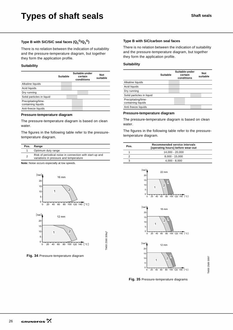
Type B with SiC/SiC seal faces (Q1G/Q1
G)
There is no relation between the indication of suitability and the pressure-temperature diagram, but together they form the application profile.
Suitability
Pressure-temperature diagram
The pressure-temperature diagram is based on clean water.
The figures in the following table refer to the pressure-temperature diagram.
Note: Noise occurs especially at low speeds.
Fig. 34 Pressure-temperature diagram
Type B with SiC/carbon seal faces
There is no relation between the indication of suitability and the pressure-temperature diagram, but together they form the application profile.
Suitability
Pressure-temperature diagram
The pressure-temperature diagram is based on clean water.
The figures in the following table refer to the pressure-temperature diagram.
Fig. 35 Pressure-temperature diagrams
SuitableSuitable under
certain conditions
Not suitable
Alkaline liquidsAcid liquidsDry runningSolid particles in liquidPrecipitating/lime-containing liquidsAnti-freeze liquids
Pos. Range1 Optimum duty range
2 Risk of periodical noise in connection with start-up and variations in pressure and temperature
TM00
259
0 30
9q7
SuitableSuitable under
certain conditions
Not suitable
Alkaline liquidsAcid liquidsDry runningSolid particles in liquidPrecipitating/lime-containing liquidsAnti-freeze liquids
Pos. Recommended service intervals [operating hours] before wear-out
1 14,000 - 20,0002 8,000 - 15,0003 4,000 - 8,000
TM00
258
9 30
97
Types of shaft seals Shaft seals
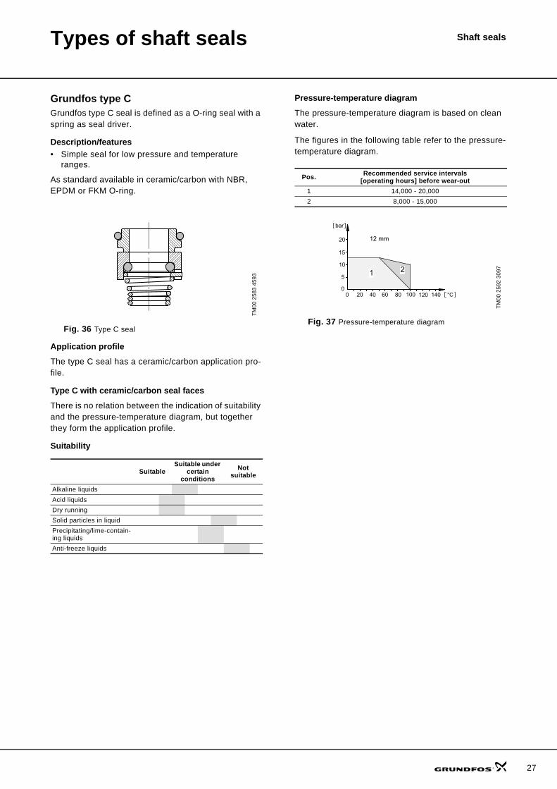
Grundfos type CGrundfos type C seal is defined as a O-ring seal with a spring as seal driver.
Description/features• Simple seal for low pressure and temperature
ranges.
As standard available in ceramic/carbon with NBR, EPDM or FKM O-ring.
Fig. 36 Type C seal
Application profile
The type C seal has a ceramic/carbon application pro-file.
Type C with ceramic/carbon seal faces
There is no relation between the indication of suitability and the pressure-temperature diagram, but together they form the application profile.
Suitability
Pressure-temperature diagram
The pressure-temperature diagram is based on clean water.
The figures in the following table refer to the pressure-temperature diagram.
Fig. 37 Pressure-temperature diagram
TM00
258
3 45
93
SuitableSuitable under
certain conditions
Not suitable
Alkaline liquidsAcid liquidsDry runningSolid particles in liquidPrecipitating/lime-contain-ing liquidsAnti-freeze liquids
Pos. Recommended service intervals [operating hours] before wear-out
1 14,000 - 20,0002 8,000 - 15,000
TM00
259
2 30
97
27

28
Types of shaft seals Shaft seals
Grundfos type DGrundfos type D seal is defined as a balanced O-ring seal.
Description/features• The design of the shaft seal makes it an ideal solu-
tion when pumping solid-containing and high-vis-cosity liquids.
• The shaft seal is independent of the direction of ro-tation.
Fig. 38 Type D seal
Application profile
The type D seal has the following application profiles:
• carbon/SiC• SiC/SiC.
Type D with carbon/SiC seal faces
Suitability
The type D seal with carbon/silicon carbide seal faces are suited for operation at temperatures from 0°C to +140°C and for an operating pressure of up to 25 bar.
Type D with SiC/SiC seal faces
There is no relation between the indication of suitability and the pressure-temperature diagram, but together they form the application profile.
Suitability
The type D seal with SiC/SiC seal faces are suited for operation at temperatures from –20°C to +90°C and at a operating pressure of up to 16 bar.
TM02
709
4 26
03
SuitableSuitable under
certain conditions
Not suitable
Alkaline liquidsAcid liquidsDry runningSolid particles in liquidPrecipitating/lime-containing liquidsAnti-freeze liquids
SuitableSuitable under
certain conditions
Not suitable
Alkaline liquidsAcid liquidsDry runningSolid particles in liquidPrecipitating/lime-containing liquidsAnti-freeze liquids
Types of shaft seals Shaft seals
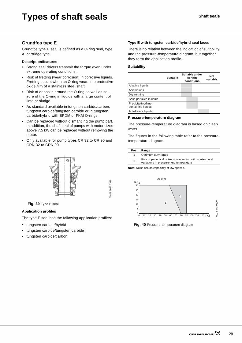
Grundfos type EGrundfos type E seal is defined as a O-ring seal, type A, cartridge type.
Description/features• Strong seal drivers transmit the torque even under
extreme operating conditions.• Risk of fretting (wear corrosion) in corrosive liquids.
Fretting occurs when an O-ring wears the protective oxide film of a stainless steel shaft.
• Risk of deposits around the O-ring as well as sei-zure of the O-ring in liquids with a large content of lime or sludge.
• As standard available in tungsten carbide/carbon, tungsten carbide/tungsten carbide or in tungsten carbide/hybrid with EPDM or FKM O-rings.
• Can be replaced without dismantling the pump part. In addition, the shaft seal of pumps with motor sizes above 7.5 kW can be replaced without removing the motor.
• Only available for pump types CR 32 to CR 90 and CRN 32 to CRN 90.
Fig. 39 Type E seal
Application profiles
The type E seal has the following application profiles:
• tungsten carbide/hybrid• tungsten carbide/tungsten carbide• tungsten carbide/carbon.
Type E with tungsten carbide/hybrid seal faces
There is no relation between the indication of suitability and the pressure-temperature diagram, but together they form the application profile.
Suitability
Pressure-temperature diagram
The pressure-temperature diagram is based on clean water.
The figures in the following table refer to the pressure-temperature diagram.
Note: Noise occurs especially at low speeds.
Fig. 40 Pressure-temperature diagram
TM01
306
5 33
98
SuitableSuitable under
certain conditions
Not suitable
Alkaline liquidsAcid liquidsDry runningSolid particles in liquidPrecipitating/lime-containing liquidsAnti-freeze liquids
Pos. Range1 Optimum duty range
2 Risk of periodical noise in connection with start-up and variations in pressure and temperature
TM01
834
3 01
00
30
25
20
15
10
5
00 10 20 30 40 50 60
22 mm
1
2
70 80 90 100 110 120
[bar]
[˚C]
29
30
Types of shaft seals Shaft seals
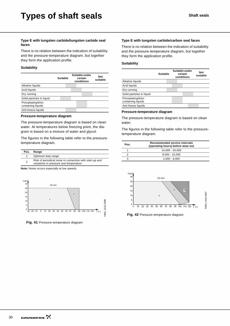
Type E with tungsten carbide/tungsten carbide seal faces
There is no relation between the indication of suitability and the pressure-temperature diagram, but together they form the application profile.
Suitability
Pressure-temperature diagram
The pressure-temperature diagram is based on clean water. At temperatures below freezing point, the dia-gram is based on a mixture of water and glycol.
The figures in the following table refer to the pressure-temperature diagram.
Note: Noise occurs especially at low speeds.
Fig. 41 Pressure-temperature diagram
Type E with tungsten carbide/carbon seal faces
There is no relation between the indication of suitability and the pressure-temperature diagram, but together they form the application profile.
Suitability
Pressure-temperature diagram
The pressure-temperature diagram is based on clean water.
The figures in the following table refer to the pressure-temperature diagram.
Fig. 42 Pressure-temperature diagram
SuitableSuitable under
certain conditions
Not suitable
Alkaline liquidsAcid liquidsDry runningSolid particles in liquidPrecipitating/lime-containing liquidsAnti-freeze liquids
Pos. Range1 Optimum duty range
2 Risk of periodical noise in connection with start-up and variations in pressure and temperature
TM01
141
6 33
98
SuitableSuitable under
certain conditions
Not suitable
Alkaline liquidsAcid liquidsDry runningSolid particles in liquidPrecipitating/lime-containing liquidsAnti-freeze liquids
Pos. Recommended service intervals [operating hours] before wear-out
1 14,000 - 20,0002 8,000 - 15,0003 4,000 - 8,000
TM01
141
8 44
97
Types of shaft seals Shaft seals
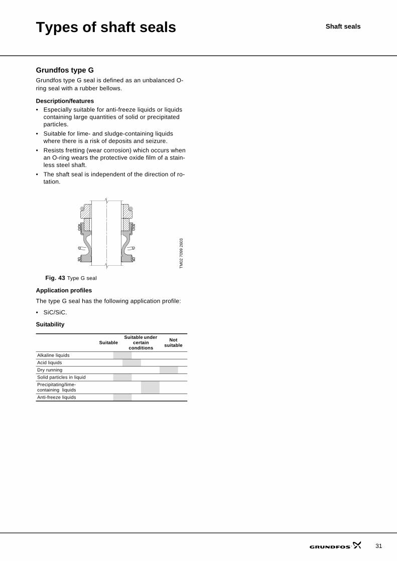
Grundfos type GGrundfos type G seal is defined as an unbalanced O-ring seal with a rubber bellows.
Description/features• Especially suitable for anti-freeze liquids or liquids
containing large quantities of solid or precipitated particles.
• Suitable for lime- and sludge-containing liquids where there is a risk of deposits and seizure.
• Resists fretting (wear corrosion) which occurs when an O-ring wears the protective oxide film of a stain-less steel shaft.
• The shaft seal is independent of the direction of ro-tation.
Fig. 43 Type G seal
Application profiles
The type G seal has the following application profile:
• SiC/SiC.
Suitability
TM02
709
9 26
03
SuitableSuitable under
certain conditions
Not suitable
Alkaline liquidsAcid liquidsDry runningSolid particles in liquidPrecipitating/lime-containing liquidsAnti-freeze liquids
31
32
Types of shaft seals Shaft seals
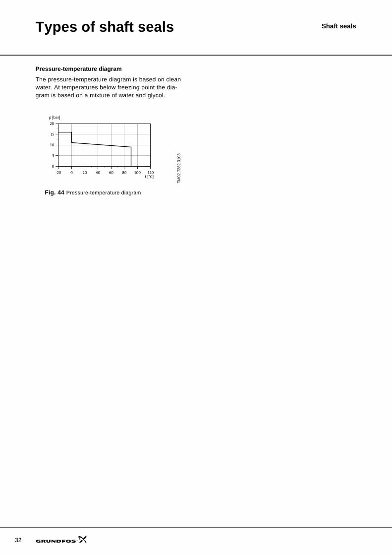
Pressure-temperature diagram
The pressure-temperature diagram is based on clean water. At temperatures below freezing point the dia-gram is based on a mixture of water and glycol.
Fig. 44 Pressure-temperature diagram
TM02
728
2 31
03-20 0 20 40 60 80 100 120
0
5
10
15
20
p [bar]
t [°C]
Types of shaft seals Shaft seals
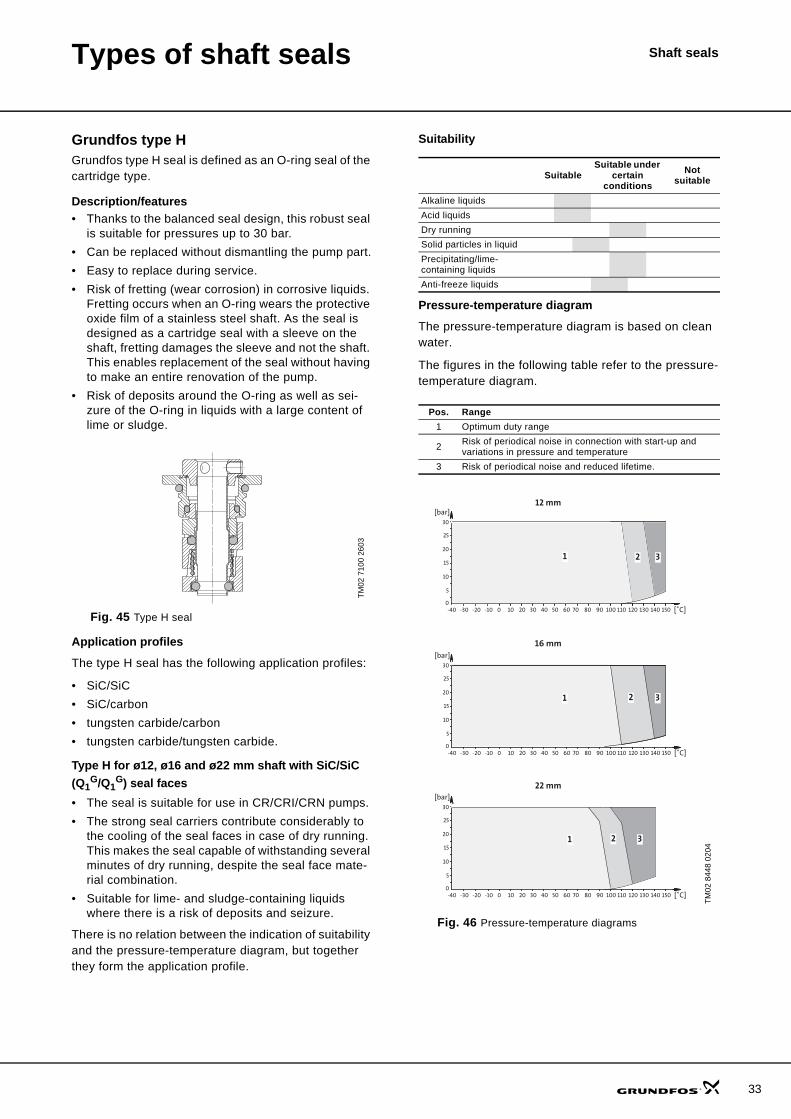
Grundfos type HGrundfos type H seal is defined as an O-ring seal of the cartridge type.
Description/features• Thanks to the balanced seal design, this robust seal
is suitable for pressures up to 30 bar.• Can be replaced without dismantling the pump part.• Easy to replace during service.• Risk of fretting (wear corrosion) in corrosive liquids.
Fretting occurs when an O-ring wears the protective oxide film of a stainless steel shaft. As the seal is designed as a cartridge seal with a sleeve on the shaft, fretting damages the sleeve and not the shaft. This enables replacement of the seal without having to make an entire renovation of the pump.
• Risk of deposits around the O-ring as well as sei-zure of the O-ring in liquids with a large content of lime or sludge.
Fig. 45 Type H seal
Application profiles
The type H seal has the following application profiles:
• SiC/SiC• SiC/carbon• tungsten carbide/carbon • tungsten carbide/tungsten carbide.
Type H for ø12, ø16 and ø22 mm shaft with SiC/SiC (Q1
G/Q1G) seal faces
• The seal is suitable for use in CR/CRI/CRN pumps. • The strong seal carriers contribute considerably to
the cooling of the seal faces in case of dry running. This makes the seal capable of withstanding several minutes of dry running, despite the seal face mate-rial combination.
• Suitable for lime- and sludge-containing liquids where there is a risk of deposits and seizure.
There is no relation between the indication of suitability and the pressure-temperature diagram, but together they form the application profile.
Suitability
Pressure-temperature diagram
The pressure-temperature diagram is based on clean water.
The figures in the following table refer to the pressure-temperature diagram.
Fig. 46 Pressure-temperature diagrams
TM02
710
0 26
03
SuitableSuitable under
certain conditions
Not suitable
Alkaline liquidsAcid liquidsDry runningSolid particles in liquidPrecipitating/lime-containing liquidsAnti-freeze liquids
Pos. Range1 Optimum duty range
2 Risk of periodical noise in connection with start-up and variations in pressure and temperature
3 Risk of periodical noise and reduced lifetime.
TM02
844
8 02
04
10 20 30 40 50 60 70 80 90 100 110 120 130 140 150 [˚C]
16 mm
30
25
20
15
10
5
00
[bar]
-40 -30 -20 -10
10 20 30 40 50 60 70 80 90 100 110 120 130 140 150 [˚C]
22 mm
00-40 -30 -20 -10
2 31
1 2 3
10 20 30 40 50 60 70 80 90 100 110 120 130 140 150 [˚C]
12 mm
30
25
20
15
10
5
00
[bar]
-40 -30 -20 -10
1 2 3
30
25
20
15
10
5
[bar]
33
34
Types of shaft seals Shaft seals
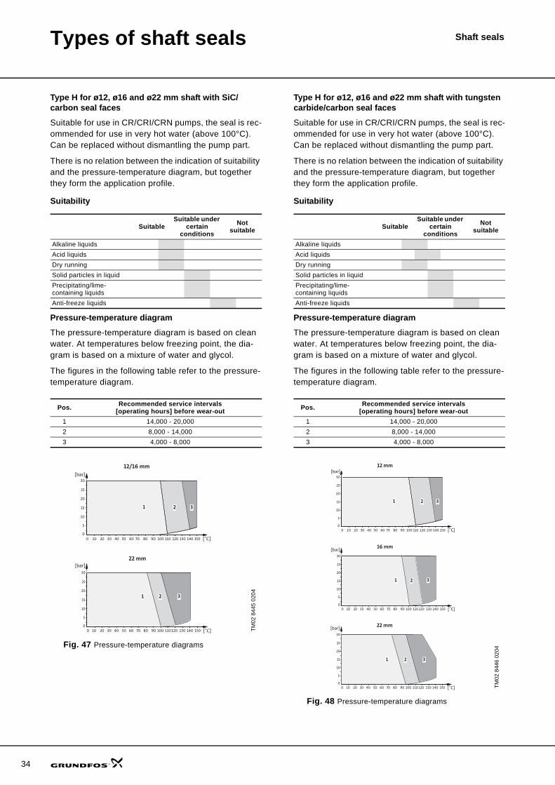
Type H for ø12, ø16 and ø22 mm shaft with SiC/carbon seal faces
Suitable for use in CR/CRI/CRN pumps, the seal is rec-ommended for use in very hot water (above 100°C). Can be replaced without dismantling the pump part.
There is no relation between the indication of suitability and the pressure-temperature diagram, but together they form the application profile.
Suitability
Pressure-temperature diagram
The pressure-temperature diagram is based on clean water. At temperatures below freezing point, the dia-gram is based on a mixture of water and glycol.
The figures in the following table refer to the pressure-temperature diagram.
Fig. 47 Pressure-temperature diagrams
Type H for ø12, ø16 and ø22 mm shaft with tungsten carbide/carbon seal faces
Suitable for use in CR/CRI/CRN pumps, the seal is rec-ommended for use in very hot water (above 100°C). Can be replaced without dismantling the pump part.
There is no relation between the indication of suitability and the pressure-temperature diagram, but together they form the application profile.
Suitability
Pressure-temperature diagram
The pressure-temperature diagram is based on clean water. At temperatures below freezing point, the dia-gram is based on a mixture of water and glycol.
The figures in the following table refer to the pressure-temperature diagram.
Fig. 48 Pressure-temperature diagrams
SuitableSuitable under
certain conditions
Not suitable
Alkaline liquidsAcid liquidsDry runningSolid particles in liquidPrecipitating/lime-containing liquidsAnti-freeze liquids
Pos. Recommended service intervals [operating hours] before wear-out
1 14,000 - 20,0002 8,000 - 14,0003 4,000 - 8,000
TM02
844
5 02
04
[bar]30
25
20
15
10
5
00 10 20 30
2
40 50 60 70 80 90 100 110 120 130 140 150
31
[˚C]
30
25
20
15
10
5
0[˚C]
1 2 3
0 10 20 30 40 50 60 70 80 90 100 110 120 130 140 150
1
[bar]
12/16 mm
22 mm
SuitableSuitable under
certain conditions
Not suitable
Alkaline liquidsAcid liquidsDry runningSolid particles in liquidPrecipitating/lime-containing liquidsAnti-freeze liquids
Pos. Recommended service intervals [operating hours] before wear-out
1 14,000 - 20,0002 8,000 - 14,0003 4,000 - 8,000
TM02
844
6 02
04
[bar]30
25
20
15
10
5
00 10 20 30
2
40 50 60 70 80 90 100 110 120 130 140 150
31
[˚C]
12 mm
16 mm
30
25
20
15
10
5
0[˚C]0 10 20 30 40 50 60 70 80 90 100 110 120 130 140 150
[bar]
11 2 3
22 mm
30
25
20
15
10
5
0[˚C]0 10 20 30 40 50 60 70 80 90 100 110 120 130 140 150
[bar]
211 32
Types of shaft seals Shaft seals
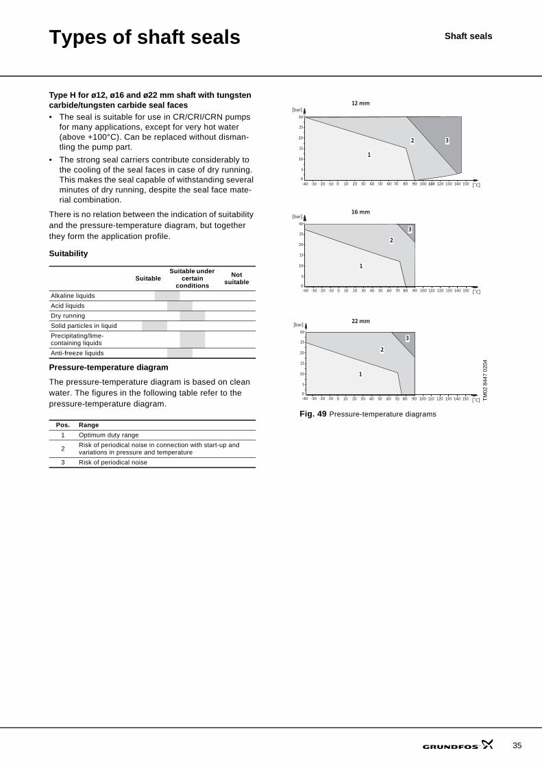
Type H for ø12, ø16 and ø22 mm shaft with tungsten carbide/tungsten carbide seal faces • The seal is suitable for use in CR/CRI/CRN pumps
for many applications, except for very hot water (above +100°C). Can be replaced without disman-tling the pump part.
• The strong seal carriers contribute considerably to the cooling of the seal faces in case of dry running. This makes the seal capable of withstanding several minutes of dry running, despite the seal face mate-rial combination.
There is no relation between the indication of suitability and the pressure-temperature diagram, but together they form the application profile.
Suitability
Pressure-temperature diagram
The pressure-temperature diagram is based on clean water. The figures in the following table refer to the pressure-temperature diagram.
Fig. 49 Pressure-temperature diagrams
SuitableSuitable under
certain conditions
Not suitable
Alkaline liquidsAcid liquidsDry runningSolid particles in liquidPrecipitating/lime-containing liquidsAnti-freeze liquids
Pos. Range1 Optimum duty range
2 Risk of periodical noise in connection with start-up and variations in pressure and temperature
3 Risk of periodical noise
TM02
844
7 02
04
30
25
20
15
10
5
00 10 20 30
2
40 50 60 70 80 90 100 110 120 130 140 150
3
1
[bar]
[˚C]
30
25
20
15
10
5
00 10 20 30 40 50 60 70 80 90 100 110 120 130 140 150
[bar]
[˚C]
12 mm
1
2
3
30
25
20
15
10
5
0 10 20 30 40 50 60 70 80 90 100 110 120 130 140 150
[bar]
[˚C]
1
3
2
16 mm
22 mm
-40 -30 -20 -10
0-40 -30 -20 -10
-40 -30 -20 -10
35
36
Types of shaft seals Shaft seals
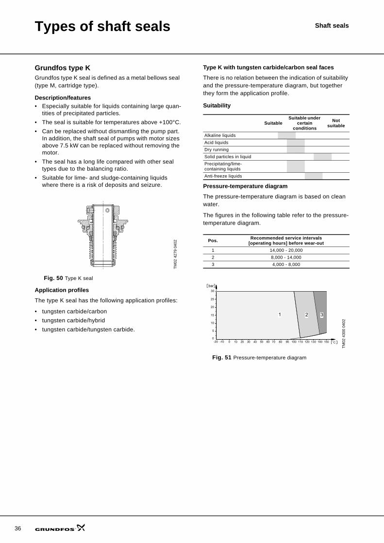
Grundfos type KGrundfos type K seal is defined as a metal bellows seal (type M, cartridge type).
Description/features• Especially suitable for liquids containing large quan-
tities of precipitated particles.• The seal is suitable for temperatures above +100°C.• Can be replaced without dismantling the pump part.
In addition, the shaft seal of pumps with motor sizes above 7.5 kW can be replaced without removing the motor.
• The seal has a long life compared with other seal types due to the balancing ratio.
• Suitable for lime- and sludge-containing liquids where there is a risk of deposits and seizure.
Fig. 50 Type K seal
Application profiles
The type K seal has the following application profiles:
• tungsten carbide/carbon• tungsten carbide/hybrid• tungsten carbide/tungsten carbide.
Type K with tungsten carbide/carbon seal faces
There is no relation between the indication of suitability and the pressure-temperature diagram, but together they form the application profile.
Suitability
Pressure-temperature diagram
The pressure-temperature diagram is based on clean water.
The figures in the following table refer to the pressure-temperature diagram.
Fig. 51 Pressure-temperature diagram
TM02
427
9 04
02
SuitableSuitable under
certain conditions
Not suitable
Alkaline liquidsAcid liquidsDry runningSolid particles in liquidPrecipitating/lime-containing liquidsAnti-freeze liquids
Pos. Recommended service intervals [operating hours] before wear-out
1 14,000 - 20,0002 8,000 - 14,0003 4,000 - 8,000
TM02
430
0 04
02
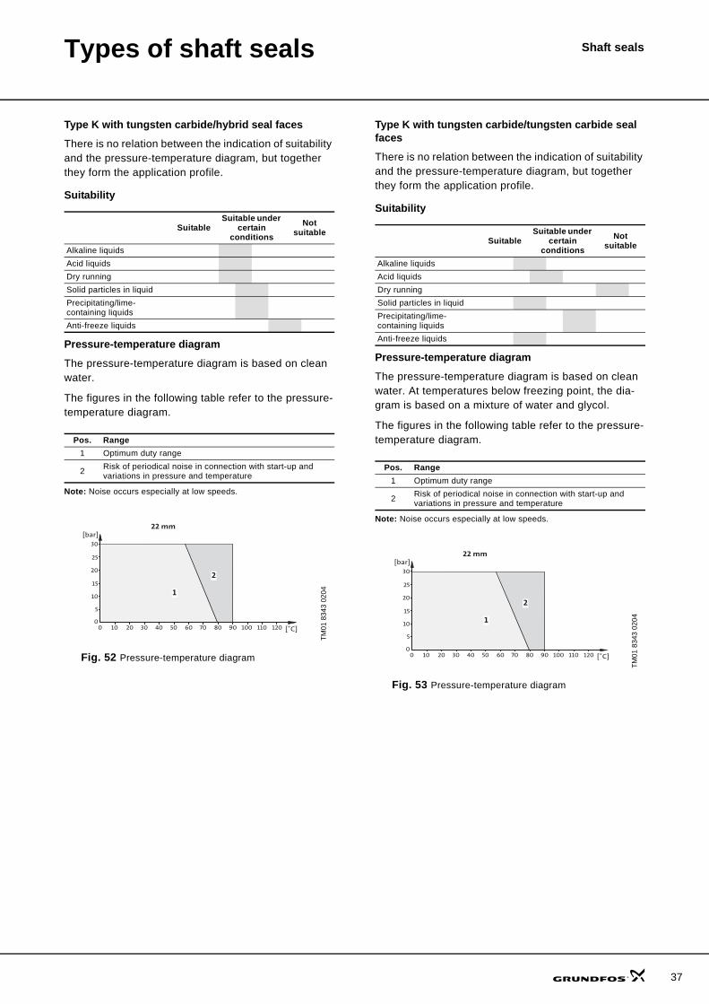
Types of shaft seals Shaft seals
Type K with tungsten carbide/hybrid seal faces
There is no relation between the indication of suitability and the pressure-temperature diagram, but together they form the application profile.
Suitability
Pressure-temperature diagram
The pressure-temperature diagram is based on clean water.
The figures in the following table refer to the pressure-temperature diagram.
Note: Noise occurs especially at low speeds.
Fig. 52 Pressure-temperature diagram
Type K with tungsten carbide/tungsten carbide seal faces
There is no relation between the indication of suitability and the pressure-temperature diagram, but together they form the application profile.
Suitability
Pressure-temperature diagram
The pressure-temperature diagram is based on clean water. At temperatures below freezing point, the dia-gram is based on a mixture of water and glycol.
The figures in the following table refer to the pressure-temperature diagram.
Note: Noise occurs especially at low speeds.
Fig. 53 Pressure-temperature diagram
SuitableSuitable under
certain conditions
Not suitable
Alkaline liquidsAcid liquidsDry runningSolid particles in liquidPrecipitating/lime-containing liquidsAnti-freeze liquids
Pos. Range1 Optimum duty range
2 Risk of periodical noise in connection with start-up and variations in pressure and temperature
TM01
834
3 02
04
30
25
20
15
10
5
00 10 20 30 40 50 60
22 mm
1
2
70 80 90 100 110 120
[bar]
[˚C]
37
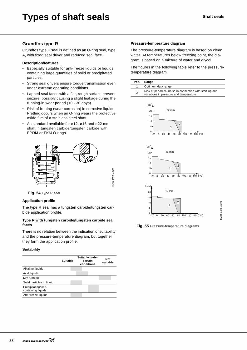
38
Types of shaft seals Shaft seals
Grundfos type RGrundfos type K seal is defined as an O-ring seal, type A, with fixed seal driver and reduced seal face.
Description/features• Especially suitable for anti-freeze liquids or liquids
containing large quantities of solid or precipitated particles.
• Strong seal drivers ensure torque transmission even under extreme operating conditions.
• Lapped seal faces with a flat, rough surface prevent seizure, possibly causing a slight leakage during the running-in wear period (10 - 30 days).
• Risk of fretting (wear corrosion) in corrosive liquids. Fretting occurs when an O-ring wears the protective oxide film of a stainless steel shaft.
• As standard available for ø12, ø16 and ø22 mm shaft in tungsten carbide/tungsten carbide with EPDM or FKM O-rings.
Fig. 54 Type R seal
Application profile
The type R seal has a tungsten carbide/tungsten car-bide application profile.
Type R with tungsten carbide/tungsten carbide seal faces
There is no relation between the indication of suitability and the pressure-temperature diagram, but together they form the application profile.
Suitability
Pressure-temperature diagram
The pressure-temperature diagram is based on clean water. At temperatures below freezing point, the dia-gram is based on a mixture of water and glycol.
The figures in the following table refer to the pressure-temperature diagram.
Fig. 55 Pressure-temperature diagrams
TM01
504
6 14
99
SuitableSuitable under
certain conditions
Not suitable
Alkaline liquidsAcid liquidsDry runningSolid particles in liquidPrecipitating/lime-containing liquidsAnti-freeze liquids
Pos. Range1 Optimum duty range
2 Risk of periodical noise in connection with start-up and variations in pressure and temperature
TM01
740
6 45
99
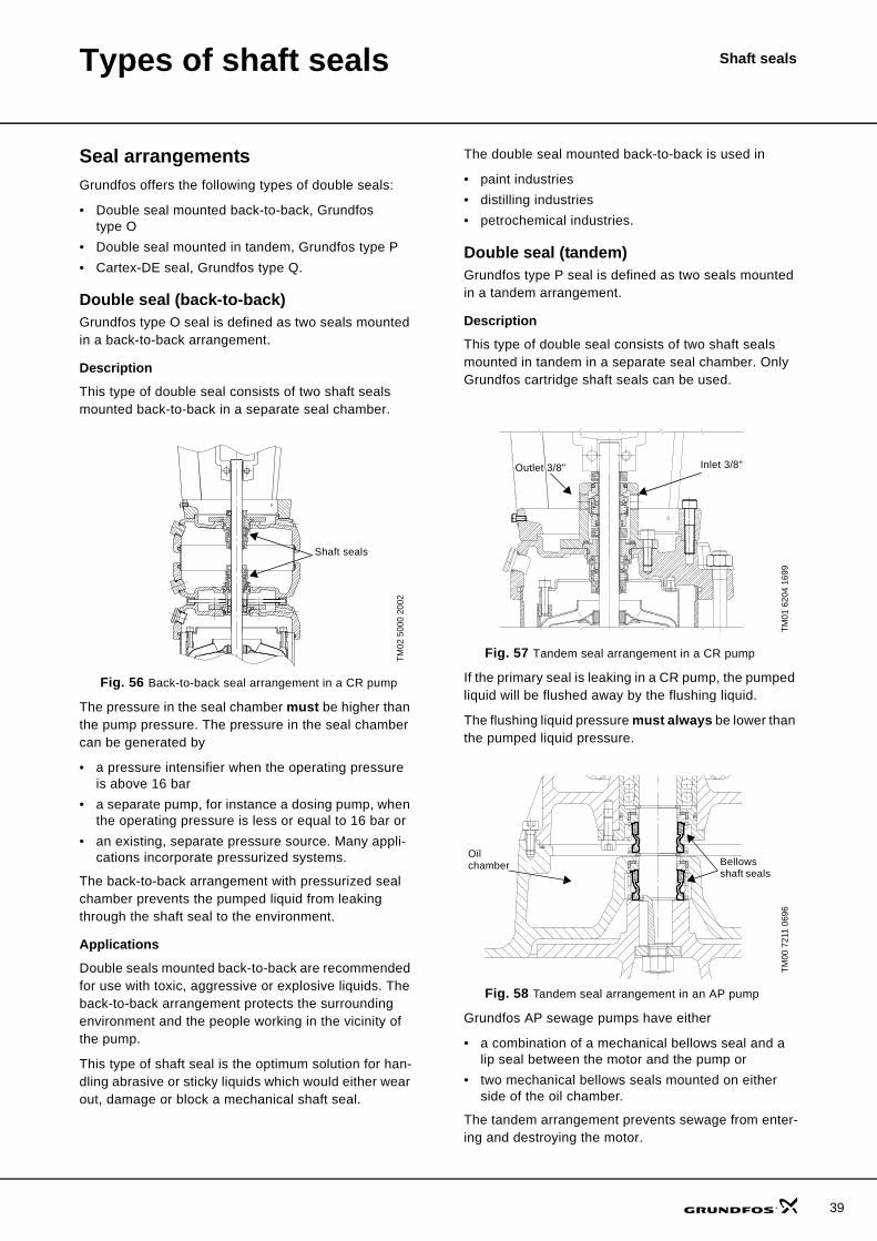
Types of shaft seals Shaft seals
Seal arrangementsGrundfos offers the following types of double seals:
• Double seal mounted back-to-back, Grundfos type O
• Double seal mounted in tandem, Grundfos type P• Cartex-DE seal, Grundfos type Q.
Double seal (back-to-back)Grundfos type O seal is defined as two seals mounted in a back-to-back arrangement.
Description
This type of double seal consists of two shaft seals mounted back-to-back in a separate seal chamber.
Fig. 56 Back-to-back seal arrangement in a CR pump
The pressure in the seal chamber must be higher than the pump pressure. The pressure in the seal chamber can be generated by
• a pressure intensifier when the operating pressure is above 16 bar
• a separate pump, for instance a dosing pump, when the operating pressure is less or equal to 16 bar or
• an existing, separate pressure source. Many appli-cations incorporate pressurized systems.
The back-to-back arrangement with pressurized seal chamber prevents the pumped liquid from leaking through the shaft seal to the environment.
Applications
Double seals mounted back-to-back are recommended for use with toxic, aggressive or explosive liquids. The back-to-back arrangement protects the surrounding environment and the people working in the vicinity of the pump.
This type of shaft seal is the optimum solution for han-dling abrasive or sticky liquids which would either wear out, damage or block a mechanical shaft seal.
The double seal mounted back-to-back is used in
• paint industries• distilling industries• petrochemical industries.
Double seal (tandem)Grundfos type P seal is defined as two seals mounted in a tandem arrangement.
Description
This type of double seal consists of two shaft seals mounted in tandem in a separate seal chamber. Only Grundfos cartridge shaft seals can be used.
Fig. 57 Tandem seal arrangement in a CR pump
If the primary seal is leaking in a CR pump, the pumped liquid will be flushed away by the flushing liquid.
The flushing liquid pressure must always be lower than the pumped liquid pressure.
Fig. 58 Tandem seal arrangement in an AP pump
Grundfos AP sewage pumps have either
• a combination of a mechanical bellows seal and a lip seal between the motor and the pump or
• two mechanical bellows seals mounted on either side of the oil chamber.
The tandem arrangement prevents sewage from enter-ing and destroying the motor.
TM02
500
0 20
02
•
Shaft seals
TM01
620
4 16
99TM
00 7
211
0696
•
• •
G 3/8"
Inlet 3/8"Outlet 3/8"
Oil chamber Bellows
shaft seals
39
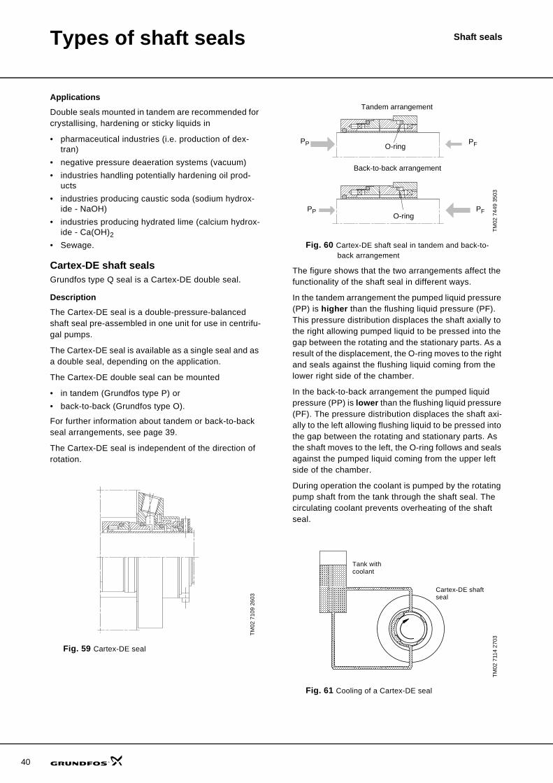
40
Types of shaft seals Shaft seals
Applications
Double seals mounted in tandem are recommended for crystallising, hardening or sticky liquids in
• pharmaceutical industries (i.e. production of dex-tran)
• negative pressure deaeration systems (vacuum)• industries handling potentially hardening oil prod-
ucts• industries producing caustic soda (sodium hydrox-
ide - NaOH)• industries producing hydrated lime (calcium hydrox-
ide - Ca(OH)2• Sewage.
Cartex-DE shaft sealsGrundfos type Q seal is a Cartex-DE double seal.
Description
The Cartex-DE seal is a double-pressure-balanced shaft seal pre-assembled in one unit for use in centrifu-gal pumps.
The Cartex-DE seal is available as a single seal and as a double seal, depending on the application.
The Cartex-DE double seal can be mounted
• in tandem (Grundfos type P) or• back-to-back (Grundfos type O).
For further information about tandem or back-to-back seal arrangements, see page 39.
The Cartex-DE seal is independent of the direction of rotation.
Fig. 59 Cartex-DE seal
Fig. 60 Cartex-DE shaft seal in tandem and back-to-back arrangement
The figure shows that the two arrangements affect the functionality of the shaft seal in different ways.
In the tandem arrangement the pumped liquid pressure (PP) is higher than the flushing liquid pressure (PF). This pressure distribution displaces the shaft axially to the right allowing pumped liquid to be pressed into the gap between the rotating and the stationary parts. As a result of the displacement, the O-ring moves to the right and seals against the flushing liquid coming from the lower right side of the chamber.
In the back-to-back arrangement the pumped liquid pressure (PP) is lower than the flushing liquid pressure (PF). The pressure distribution displaces the shaft axi-ally to the left allowing flushing liquid to be pressed into the gap between the rotating and stationary parts. As the shaft moves to the left, the O-ring follows and seals against the pumped liquid coming from the upper left side of the chamber.
During operation the coolant is pumped by the rotating pump shaft from the tank through the shaft seal. The circulating coolant prevents overheating of the shaft seal.
Fig. 61 Cooling of a Cartex-DE seal
TM02
710
9 26
03
TM02
744
9 35
03TM
02 7
114
2703
PP PF
PFPP
O-ring
O-ring
Tandem arrangement
Back-to-back arrangement
Cartex-DE shaft seal
Tank with coolant
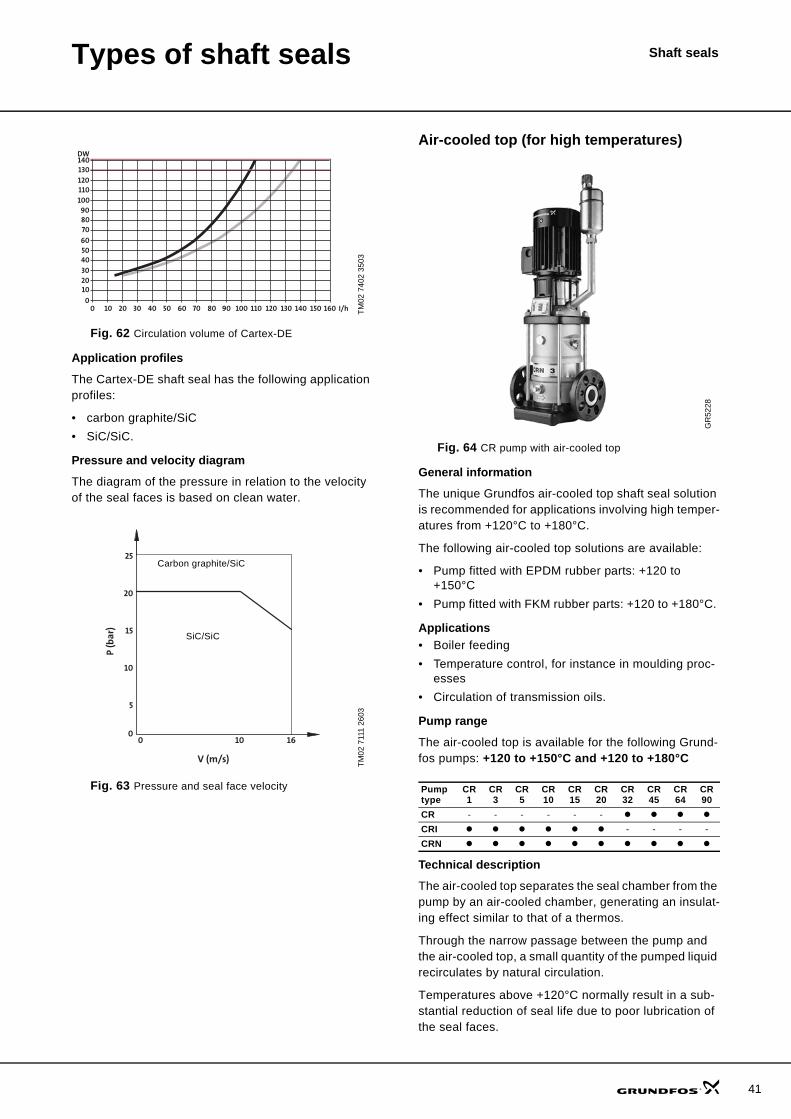
Types of shaft seals Shaft seals
Fig. 62 Circulation volume of Cartex-DE
Application profiles
The Cartex-DE shaft seal has the following application profiles:
• carbon graphite/SiC• SiC/SiC.
Pressure and velocity diagram
The diagram of the pressure in relation to the velocity of the seal faces is based on clean water.
Fig. 63 Pressure and seal face velocity
Air-cooled top (for high temperatures)
Fig. 64 CR pump with air-cooled top
General information
The unique Grundfos air-cooled top shaft seal solution is recommended for applications involving high temper-atures from +120°C to +180°C.
The following air-cooled top solutions are available:
• Pump fitted with EPDM rubber parts: +120 to +150°C
• Pump fitted with FKM rubber parts: +120 to +180°C.
Applications• Boiler feeding• Temperature control, for instance in moulding proc-
esses• Circulation of transmission oils.
Pump range
The air-cooled top is available for the following Grund-fos pumps: +120 to +150°C and +120 to +180°C
Technical description
The air-cooled top separates the seal chamber from the pump by an air-cooled chamber, generating an insulat-ing effect similar to that of a thermos.
Through the narrow passage between the pump and the air-cooled top, a small quantity of the pumped liquid recirculates by natural circulation.
Temperatures above +120°C normally result in a sub-stantial reduction of seal life due to poor lubrication of the seal faces.
TM02
740
2 35
03TM
02 7
111
2603
00
102030405060
708090
100110120130140DW
10 20 30 40 50 60 70 80 90 100 110 120 130 140 I/h150 160
160 10
5
10
15
20
25
0
V (m/s)
P (b
ar)
Carbon graphite/SiC
SiC/SiC
GR
5228
Pump type
CR 1
CR 3
CR 5
CR 10
CR 15
CR 20
CR 32
CR 45
CR 64
CR90
CR - - - - - -CRI - - - -CRN
41
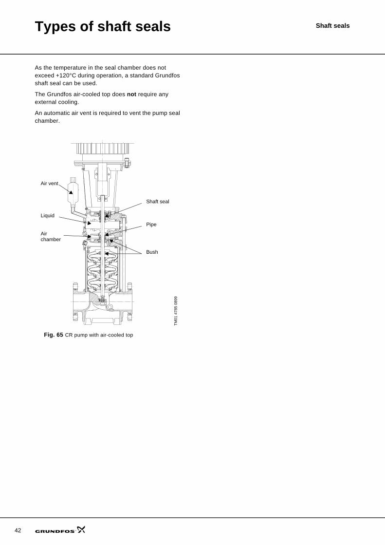
42
Types of shaft seals Shaft seals
As the temperature in the seal chamber does not exceed +120°C during operation, a standard Grundfos shaft seal can be used.
The Grundfos air-cooled top does not require any external cooling.
An automatic air vent is required to vent the pump seal chamber.
Fig. 65 CR pump with air-cooled top
TM01
478
5 08
99
••
• •
•
•
•
•
•
Air vent
Liquid
Airchamber
Shaft seal
Pipe
Bush
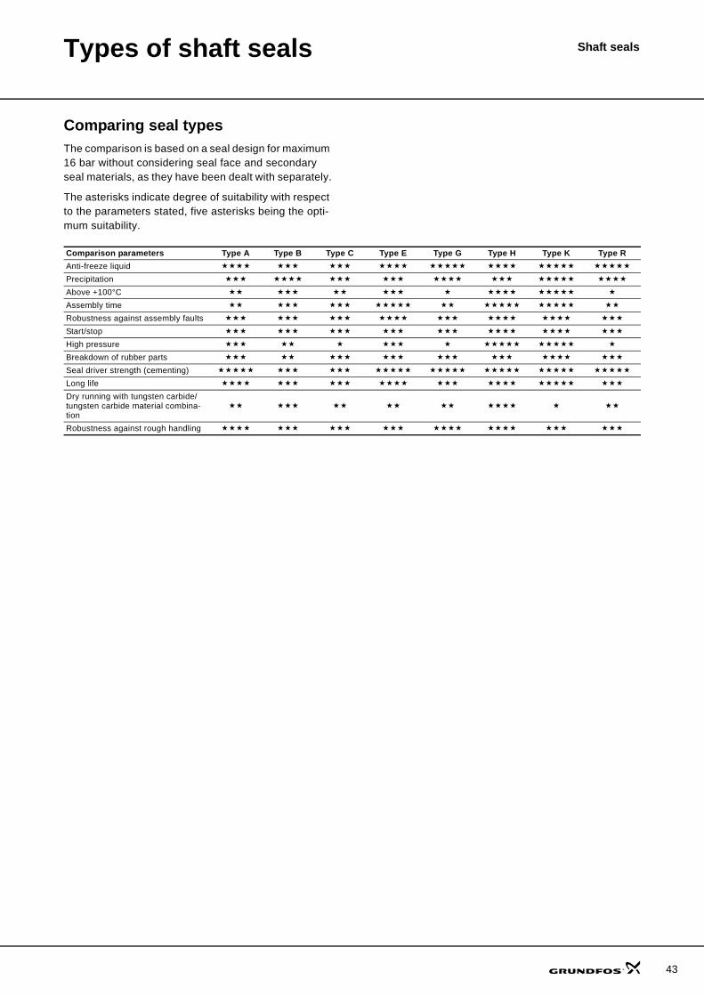
Types of shaft seals Shaft seals
Comparing seal typesThe comparison is based on a seal design for maximum 16 bar without considering seal face and secondary seal materials, as they have been dealt with separately.
The asterisks indicate degree of suitability with respect to the parameters stated, five asterisks being the opti-mum suitability.
Comparison parameters Type A Type B Type C Type E Type G Type H Type K Type RAnti-freeze liquidPrecipitationAbove +100°CAssembly timeRobustness against assembly faultsStart/stopHigh pressureBreakdown of rubber partsSeal driver strength (cementing)Long lifeDry running with tungsten carbide/tungsten carbide material combina-tionRobustness against rough handling
43
Shaft seals
44
Selection of shaft seals
Selection of the most suitable shaft sealThe list of pumped liquids in a data booklet often indi-cates several suitable shaft seals for the pumping of thesame liquid.
As the properties of the suitable shaft seals often differ,the purpose of this section is to give an example of howto select the most suitable shaft seal.
Example
The following data is assumed:
Application: Shaft seal fitted in boilerfeed pump, type CR
Operating pressure: 26 bar
Operating temperature: +115 °C
In the CR, CRI, CRN, CRE, CRIE, CRNE data bookletonly one shaft seal, HQQE, is recommended forpumping boiler water. On the other hand the HQQEshaft seal is not the only shaft seal available for thispump and application. As will appear from the descrip-tion of the various shaft seal types in this data booklet,the following seal types are suitable:• HQQE (recommended shaft seal)• HQQV• HUBE• BUBE• AUUE.
Comparing maximum operating pressures
Comparing the maximum operating pressure range of the above shaft seal types, it appears that
• the HQQE shaft seal is suitable because the operat-ing pressure of the boiler feed pump does not ex-ceed the 30 bar maximum operating pressure of the shaft seal, see "Grundfos type H" on page 33.
• the HQQV shaft seal is suitable because the operat-ing pressure of the boiler feed pump does not ex-ceed the 30 bar maximum operating pressure of the shaft seal, see "Grundfos type H" on page 33.
• the HUBE shaft seal is suitable because the operat-ing pressure of the boiler feed pump does not ex-ceed the 30 bar maximum operating pressure of the shaft seal, see "Grundfos type H" on page 33.
• the BUBE shaft seal is not suitable because the maximum operating pressure of the shaft seal is 16 bar, see "Grundfos type B" on page 25.
• The AUUE shaft seal is not suitable because the maximum operating pressure of the shaft seal is 25 bar, see "Grundfos type A" on page 24.
This leads to the conclusion that among the shaft sealsindicated, only the type H shaft seals, HUBE, HQQEand HQQV, are suitable.
Comparing maximum operating temperatures
As the HUBE, HQQE and HQQV seals have differentsecondary seal materials, the maximum operatingtemperature of the seals may differ.
Position 4 of the shaft seal configuration, for instanceHUBE, shows the secondary seal material. For furtherinformation see page 6.
Shaft seals with an EPDM secondary seal resist watertemperatures up to +140°C, see "EPDM" on page 23. Shaft seals with an FKM secondary seal resist watertemperatures up to +90°C, see "FKM" on page 23.
This leaves only two suitable shaft seals, HUBE andHQQE.
Resistance to abrasive particles
The high pumped liquid temperature above +60°C maycause lime to precipitate in the pumped liquid resultingin scale formation. Deposits on the seal faces mayresult in wear and reduced seal life.
According to the Grundfos type designation, the HUBEseal face material combination is tungsten carbide/carbon, see page 5. This tungsten carbide/carbonmaterial combination offers low-noise operation.However, the deposits between the seal faces will leadto reduced seal life.
The HQQE seal face material combination is siliconcarbide/silicon carbide (SiC/SiC), see page 5. Underthe operating conditions in this example, the SiC/SiCmaterial combination offers long life as compared to theHUBE seal. However, the shaft seal will emit morenoise on account of the materials used.
Finally, the shaft seal that best matches the require-ments of the particular application is to be selected:
As a boiler feed pump is usually not located in noise-critical environments, an HQQE shaft seal is preferred on account of its long life. If an HQQE shaft seal is selected, a higher noise level must be accepted.
Shaft sealsPumped liquids
Lists of pumped liquidsThe following tables indicate the suitability of the indi-vidual shaft seals in various pumped liquids. The suita-bility only applies to the mechanical shaft seal and is not related to pumps in general.
The suitability of the individual seal combinations is based on the information on temperature, concentra-tion, etc. given in the tables. Changes in these condi-tions will affect the suitability of the seal.
Intended as a guide, the lists of pumped liquids are based on the latest knowledge and experience.
As the lists of pumped liquids do not state the toxicity class of the individual liquids, it does not clearly appear from the lists whether the seal is appropriate for the task in question in order to avoid health hazards (corro-sion, poisoning, etc.).
45
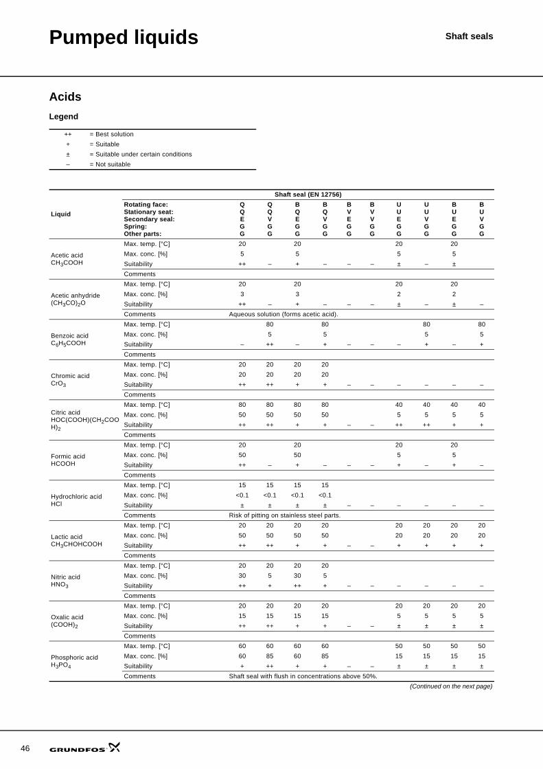
46
Pumped liquids Shaft seals
AcidsLegend
++ = Best solution+ = Suitable± = Suitable under certain conditions– = Not suitable
Liquid
Shaft seal (EN 12756)Rotating face:Stationary seat:Secondary seal:Spring:Other parts:
QQEGG
QQVGG
BQEGG
BQVGG
BVEGG
BVVGG
UUEGG
UUVGG
BUEGG
BUVGG
Acetic acidCH3COOH
Max. temp. [°C] 20 20 20 20Max. conc. [%] 5 5 5 5Suitability ++ – + – – – ± – ±Comments
Acetic anhydride(CH3CO)2O
Max. temp. [°C] 20 20 20 20Max. conc. [%] 3 3 2 2Suitability ++ – + – – – ± – ± –Comments Aqueous solution (forms acetic acid).
Benzoic acidC6H5COOH
Max. temp. [°C] 80 80 80 80Max. conc. [%] 5 5 5 5Suitability – ++ – + – – – + – +Comments
Chromic acidCrO3
Max. temp. [°C] 20 20 20 20Max. conc. [%] 20 20 20 20Suitability ++ ++ + + – – – – – –Comments
Citric acidHOC(COOH)(CH2COOH)2
Max. temp. [°C] 80 80 80 80 40 40 40 40Max. conc. [%] 50 50 50 50 5 5 5 5Suitability ++ ++ + + – – ++ ++ + +Comments
Formic acidHCOOH
Max. temp. [°C] 20 20 20 20Max. conc. [%] 50 50 5 5Suitability ++ – + – – – + – + –Comments
Hydrochloric acidHCl
Max. temp. [°C] 15 15 15 15Max. conc. [%] <0.1 <0.1 <0.1 <0.1Suitability ± ± ± ± – – – – – –Comments Risk of pitting on stainless steel parts.
Lactic acidCH3CHOHCOOH
Max. temp. [°C] 20 20 20 20 20 20 20 20Max. conc. [%] 50 50 50 50 20 20 20 20Suitability ++ ++ + + – – + + + +Comments
Nitric acidHNO3
Max. temp. [°C] 20 20 20 20Max. conc. [%] 30 5 30 5Suitability ++ + ++ + – – – – – –Comments
Oxalic acid(COOH)2
Max. temp. [°C] 20 20 20 20 20 20 20 20Max. conc. [%] 15 15 15 15 5 5 5 5Suitability ++ ++ + + – – ± ± ± ±Comments
Phosphoric acidH3PO4
Max. temp. [°C] 60 60 60 60 50 50 50 50Max. conc. [%] 60 85 60 85 15 15 15 15Suitability + ++ + + – – ± ± ± ±Comments Shaft seal with flush in concentrations above 50%.
(Continued on the next page)
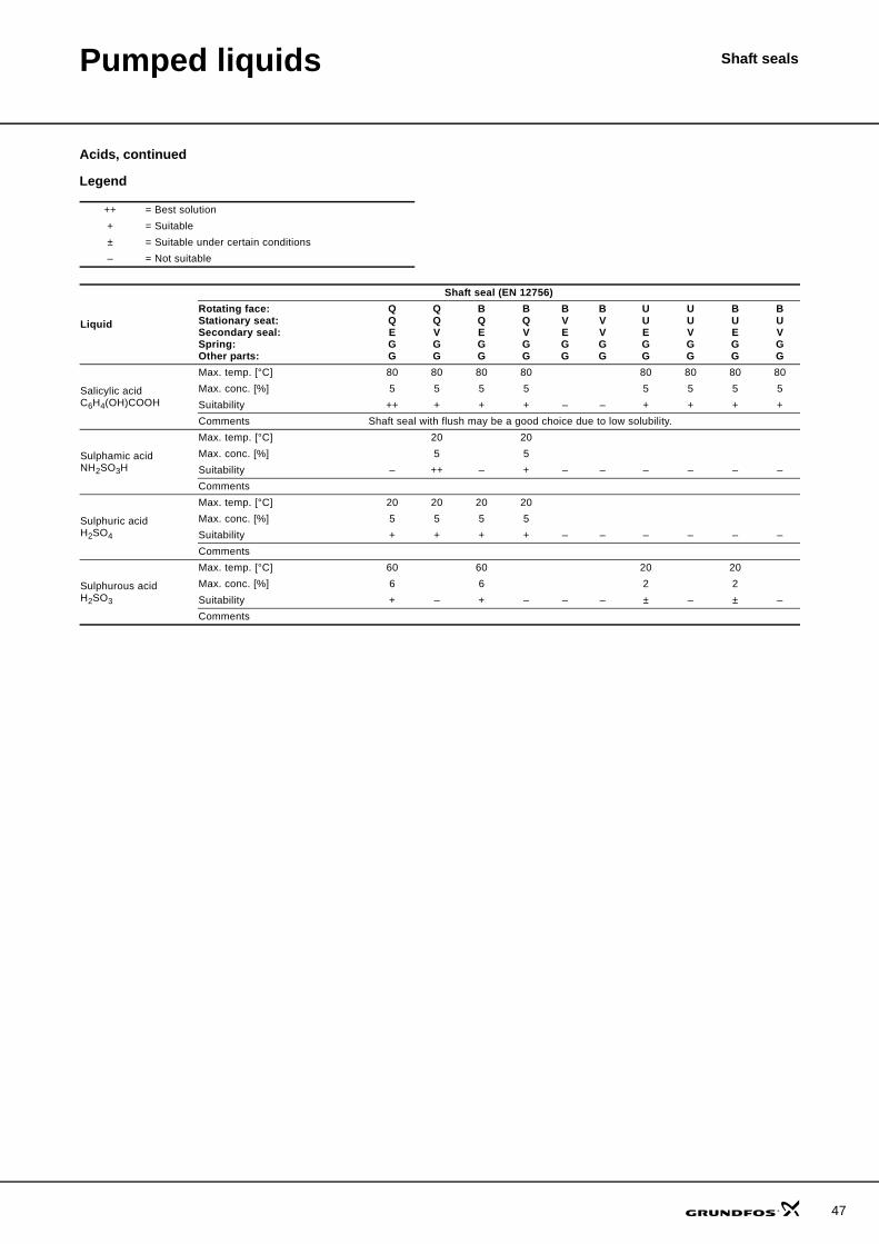
Pumped liquids Shaft seals
Acids, continued
Legend
++ = Best solution+ = Suitable± = Suitable under certain conditions– = Not suitable
Liquid
Shaft seal (EN 12756)Rotating face:Stationary seat:Secondary seal:Spring:Other parts:
QQEGG
QQVGG
BQEGG
BQVGG
BVEGG
BVVGG
UUEGG
UUVGG
BUEGG
BUVGG
Salicylic acidC6H4(OH)COOH
Max. temp. [°C] 80 80 80 80 80 80 80 80Max. conc. [%] 5 5 5 5 5 5 5 5Suitability ++ + + + – – + + + +Comments Shaft seal with flush may be a good choice due to low solubility.
Sulphamic acidNH2SO3H
Max. temp. [°C] 20 20Max. conc. [%] 5 5Suitability – ++ – + – – – – – –Comments
Sulphuric acidH2SO4
Max. temp. [°C] 20 20 20 20Max. conc. [%] 5 5 5 5Suitability + + + + – – – – – –Comments
Sulphurous acidH2SO3
Max. temp. [°C] 60 60 20 20Max. conc. [%] 6 6 2 2Suitability + – + – – – ± – ± –Comments
47
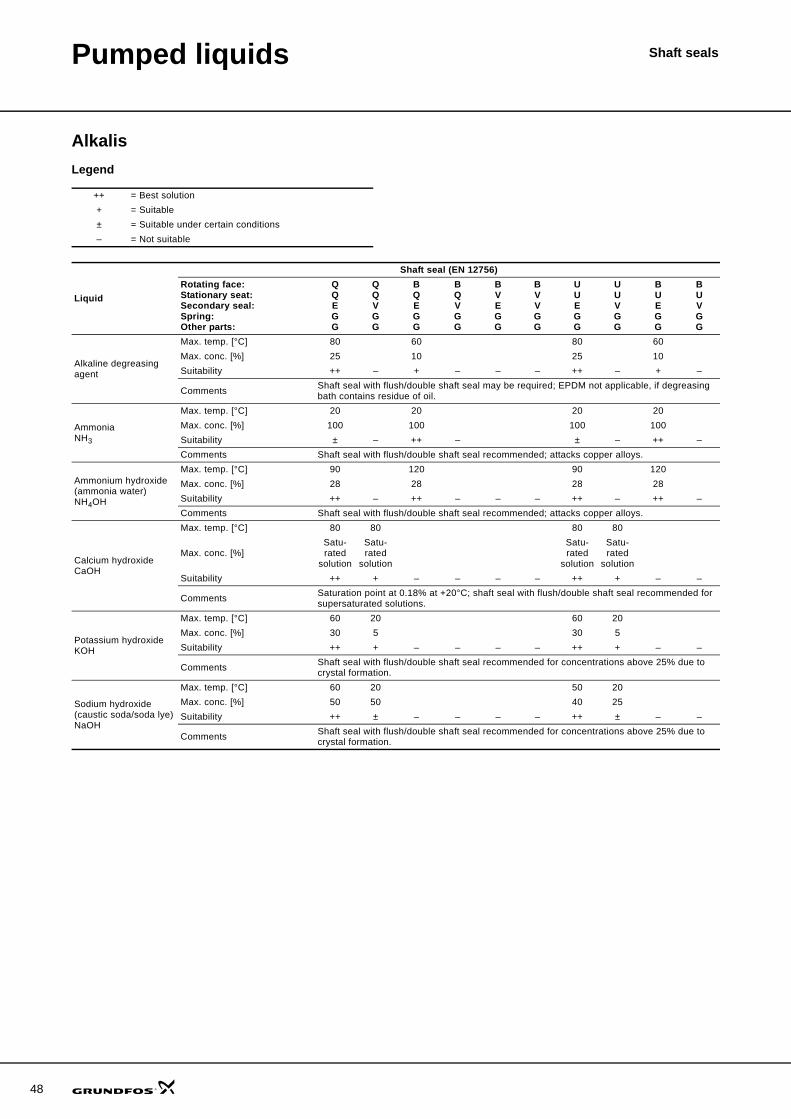
48
Pumped liquids Shaft seals
AlkalisLegend
++ = Best solution+ = Suitable± = Suitable under certain conditions– = Not suitable
Liquid
Shaft seal (EN 12756)Rotating face:Stationary seat:Secondary seal:Spring:Other parts:
QQEGG
QQVGG
BQEGG
BQVGG
BVEGG
BVVGG
UUEGG
UUVGG
BUEGG
BUVGG
Alkaline degreasing agent
Max. temp. [°C] 80 60 80 60Max. conc. [%] 25 10 25 10Suitability ++ – + – – – ++ – + –
Comments Shaft seal with flush/double shaft seal may be required; EPDM not applicable, if degreasing bath contains residue of oil.
AmmoniaNH3
Max. temp. [°C] 20 20 20 20Max. conc. [%] 100 100 100 100Suitability ± – ++ – ± – ++ –Comments Shaft seal with flush/double shaft seal recommended; attacks copper alloys.
Ammonium hydroxide(ammonia water)NH4OH
Max. temp. [°C] 90 120 90 120Max. conc. [%] 28 28 28 28Suitability ++ – ++ – – – ++ – ++ –Comments Shaft seal with flush/double shaft seal recommended; attacks copper alloys.
Calcium hydroxideCaOH
Max. temp. [°C] 80 80 80 80
Max. conc. [%]Satu-rated
solution
Satu-rated
solution
Satu-rated
solution
Satu-rated
solutionSuitability ++ + – – – – ++ + – –
Comments Saturation point at 0.18% at +20°C; shaft seal with flush/double shaft seal recommended for supersaturated solutions.
Potassium hydroxideKOH
Max. temp. [°C] 60 20 60 20Max. conc. [%] 30 5 30 5Suitability ++ + – – – – ++ + – –
Comments Shaft seal with flush/double shaft seal recommended for concentrations above 25% due to crystal formation.
Sodium hydroxide(caustic soda/soda lye)NaOH
Max. temp. [°C] 60 20 50 20Max. conc. [%] 50 50 40 25Suitability ++ ± – – – – ++ ± – –
Comments Shaft seal with flush/double shaft seal recommended for concentrations above 25% due to crystal formation.
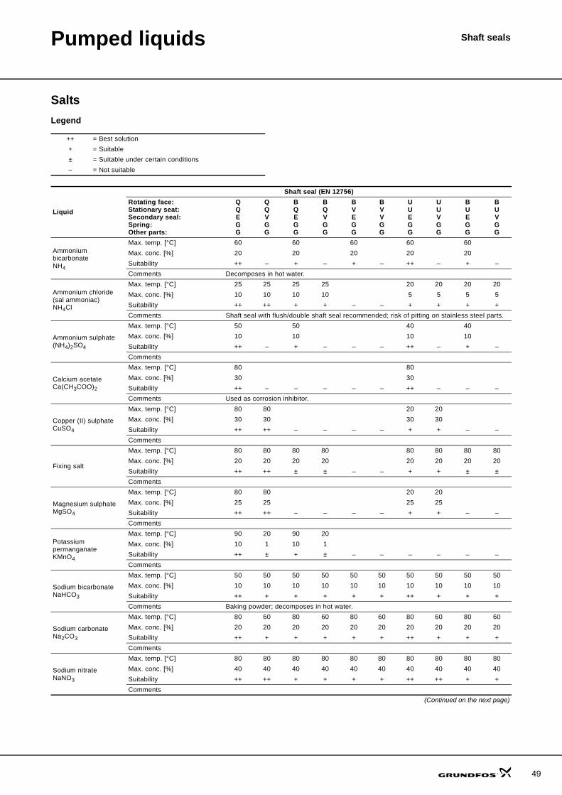
Pumped liquids Shaft seals
SaltsLegend
++ = Best solution+ = Suitable± = Suitable under certain conditions– = Not suitable
Liquid
Shaft seal (EN 12756)Rotating face:Stationary seat:Secondary seal:Spring:Other parts:
QQEGG
QQVGG
BQEGG
BQVGG
BVEGG
BVVGG
UUEGG
UUVGG
BUEGG
BUVGG
Ammonium bicarbonateNH4
Max. temp. [°C] 60 60 60 60 60Max. conc. [%] 20 20 20 20 20Suitability ++ – + – + – ++ – + –Comments Decomposes in hot water.
Ammonium chloride(sal ammoniac)NH4Cl
Max. temp. [°C] 25 25 25 25 20 20 20 20Max. conc. [%] 10 10 10 10 5 5 5 5Suitability ++ ++ + + – – + + + +Comments Shaft seal with flush/double shaft seal recommended; risk of pitting on stainless steel parts.
Ammonium sulphate(NH4)2SO4
Max. temp. [°C] 50 50 40 40Max. conc. [%] 10 10 10 10Suitability ++ – + – – – ++ – + –Comments
Calcium acetateCa(CH3COO)2
Max. temp. [°C] 80 80Max. conc. [%] 30 30Suitability ++ – – – – – ++ – – –Comments Used as corrosion inhibitor.
Copper (II) sulphateCuSO4
Max. temp. [°C] 80 80 20 20Max. conc. [%] 30 30 30 30Suitability ++ ++ – – – – + + – –Comments
Fixing salt
Max. temp. [°C] 80 80 80 80 80 80 80 80Max. conc. [%] 20 20 20 20 20 20 20 20Suitability ++ ++ ± ± – – + + ± ±Comments
Magnesium sulphateMgSO4
Max. temp. [°C] 80 80 20 20Max. conc. [%] 25 25 25 25Suitability ++ ++ – – – – + + – –Comments
Potassium permanganateKMnO4
Max. temp. [°C] 90 20 90 20Max. conc. [%] 10 1 10 1Suitability ++ ± + ± – – – – – –Comments
Sodium bicarbonateNaHCO3
Max. temp. [°C] 50 50 50 50 50 50 50 50 50 50Max. conc. [%] 10 10 10 10 10 10 10 10 10 10Suitability ++ + + + + + ++ + + +Comments Baking powder; decomposes in hot water.
Sodium carbonateNa2CO3
Max. temp. [°C] 80 60 80 60 80 60 80 60 80 60Max. conc. [%] 20 20 20 20 20 20 20 20 20 20Suitability ++ + + + + + ++ + + +Comments
Sodium nitrateNaNO3
Max. temp. [°C] 80 80 80 80 80 80 80 80 80 80Max. conc. [%] 40 40 40 40 40 40 40 40 40 40Suitability ++ ++ + + + + ++ ++ + +Comments
(Continued on the next page)
49
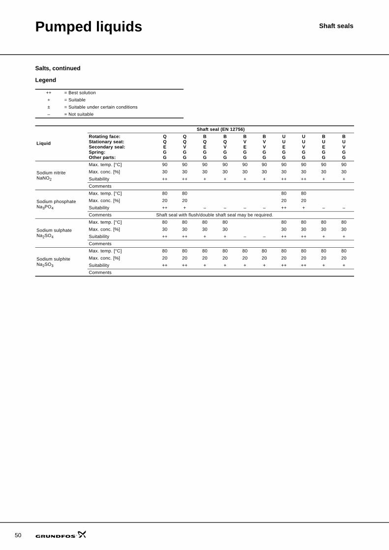
50
Pumped liquids Shaft seals
Salts, continued
Legend
++ = Best solution+ = Suitable± = Suitable under certain conditions– = Not suitable
Liquid
Shaft seal (EN 12756)Rotating face:Stationary seat:Secondary seal:Spring:Other parts:
QQEGG
QQVGG
BQEGG
BQVGG
BVEGG
BVVGG
UUEGG
UUVGG
BUEGG
BUVGG
Sodium nitriteNaNO2
Max. temp. [°C] 90 90 90 90 90 90 90 90 90 90Max. conc. [%] 30 30 30 30 30 30 30 30 30 30Suitability ++ ++ + + + + ++ ++ + +Comments
Sodium phosphateNa3PO4
Max. temp. [°C] 80 80 80 80Max. conc. [%] 20 20 20 20Suitability ++ + – – – – ++ + – –Comments Shaft seal with flush/double shaft seal may be required.
Sodium sulphateNa2SO4
Max. temp. [°C] 80 80 80 80 80 80 80 80Max. conc. [%] 30 30 30 30 30 30 30 30Suitability ++ ++ + + – – ++ ++ + +Comments
Sodium sulphiteNa2SO3
Max. temp. [°C] 80 80 80 80 80 80 80 80 80 80Max. conc. [%] 20 20 20 20 20 20 20 20 20 20Suitability ++ ++ + + + + ++ ++ + +Comments
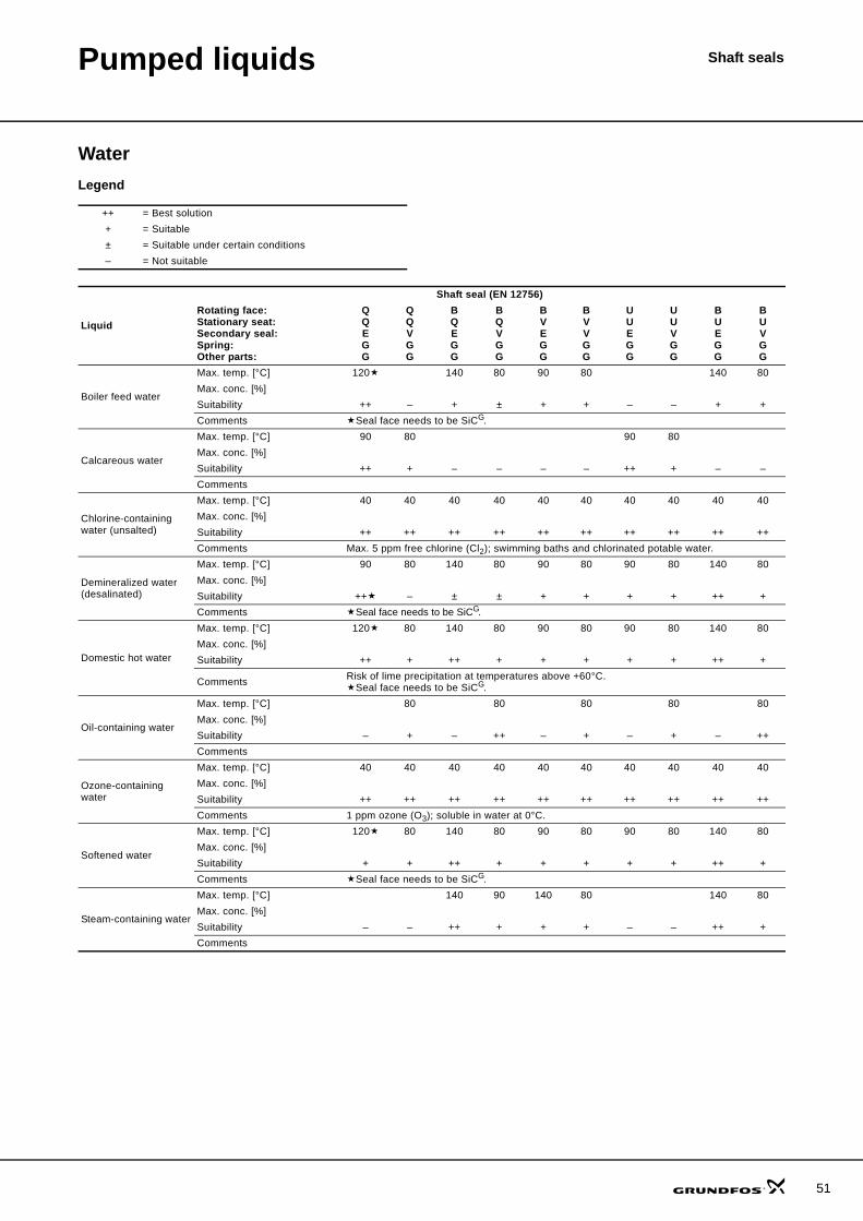
Pumped liquids Shaft seals
WaterLegend
++ = Best solution+ = Suitable± = Suitable under certain conditions– = Not suitable
Liquid
Shaft seal (EN 12756)Rotating face:Stationary seat:Secondary seal:Spring:Other parts:
QQEGG
QQVGG
BQEGG
BQVGG
BVEGG
BVVGG
UUEGG
UUVGG
BUEGG
BUVGG
Boiler feed water
Max. temp. [°C] 120 140 80 90 80 140 80Max. conc. [%]Suitability ++ – + ± + + – – + +Comments Seal face needs to be SiCG.
Calcareous water
Max. temp. [°C] 90 80 90 80Max. conc. [%]Suitability ++ + – – – – ++ + – –Comments
Chlorine-containing water (unsalted)
Max. temp. [°C] 40 40 40 40 40 40 40 40 40 40Max. conc. [%]Suitability ++ ++ ++ ++ ++ ++ ++ ++ ++ ++Comments Max. 5 ppm free chlorine (Cl2); swimming baths and chlorinated potable water.
Demineralized water (desalinated)
Max. temp. [°C] 90 80 140 80 90 80 90 80 140 80Max. conc. [%]Suitability ++ – ± ± + + + + ++ +Comments Seal face needs to be SiCG.
Domestic hot water
Max. temp. [°C] 120 80 140 80 90 80 90 80 140 80Max. conc. [%]Suitability ++ + ++ + + + + + ++ +
Comments Risk of lime precipitation at temperatures above +60°C.Seal face needs to be SiCG.
Oil-containing water
Max. temp. [°C] 80 80 80 80 80Max. conc. [%]Suitability – + – ++ – + – + – ++Comments
Ozone-containing water
Max. temp. [°C] 40 40 40 40 40 40 40 40 40 40Max. conc. [%]Suitability ++ ++ ++ ++ ++ ++ ++ ++ ++ ++Comments 1 ppm ozone (O3); soluble in water at 0°C.
Softened water
Max. temp. [°C] 120 80 140 80 90 80 90 80 140 80Max. conc. [%]Suitability + + ++ + + + + + ++ +Comments Seal face needs to be SiCG.
Steam-containing water
Max. temp. [°C] 140 90 140 80 140 80Max. conc. [%]Suitability – – ++ + + + – – ++ +Comments
51
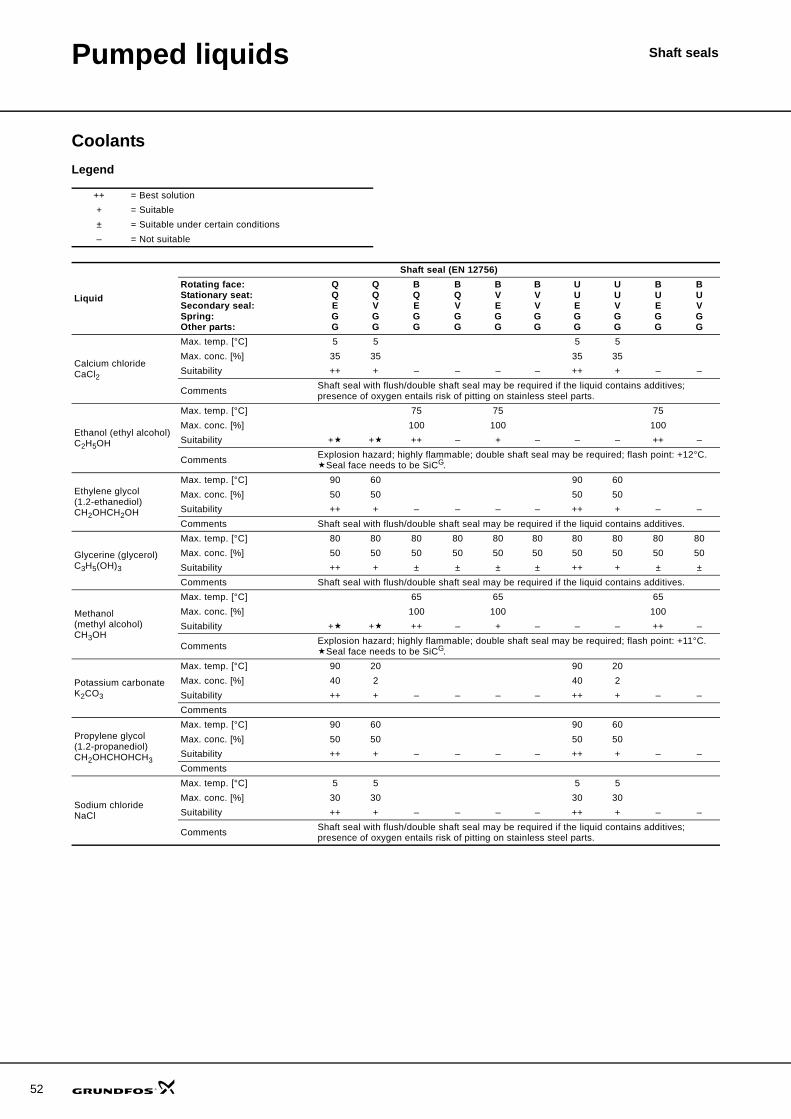
52
Pumped liquids Shaft seals
CoolantsLegend
++ = Best solution+ = Suitable± = Suitable under certain conditions– = Not suitable
Liquid
Shaft seal (EN 12756)Rotating face:Stationary seat:Secondary seal:Spring:Other parts:
QQEGG
QQVGG
BQEGG
BQVGG
BVEGG
BVVGG
UUEGG
UUVGG
BUEGG
BUVGG
Calcium chlorideCaCl2
Max. temp. [°C] 5 5 5 5Max. conc. [%] 35 35 35 35Suitability ++ + – – – – ++ + – –
Comments Shaft seal with flush/double shaft seal may be required if the liquid contains additives; presence of oxygen entails risk of pitting on stainless steel parts.
Ethanol (ethyl alcohol)C2H5OH
Max. temp. [°C] 75 75 75Max. conc. [%] 100 100 100Suitability + + ++ – + – – – ++ –
Comments Explosion hazard; highly flammable; double shaft seal may be required; flash point: +12°C.Seal face needs to be SiCG.
Ethylene glycol(1.2-ethanediol)CH2OHCH2OH
Max. temp. [°C] 90 60 90 60Max. conc. [%] 50 50 50 50Suitability ++ + – – – – ++ + – –Comments Shaft seal with flush/double shaft seal may be required if the liquid contains additives.
Glycerine (glycerol)C3H5(OH)3
Max. temp. [°C] 80 80 80 80 80 80 80 80 80 80Max. conc. [%] 50 50 50 50 50 50 50 50 50 50Suitability ++ + ± ± ± ± ++ + ± ±Comments Shaft seal with flush/double shaft seal may be required if the liquid contains additives.
Methanol (methyl alcohol)CH3OH
Max. temp. [°C] 65 65 65Max. conc. [%] 100 100 100Suitability + + ++ – + – – – ++ –
Comments Explosion hazard; highly flammable; double shaft seal may be required; flash point: +11°C.Seal face needs to be SiCG.
Potassium carbonateK2CO3
Max. temp. [°C] 90 20 90 20Max. conc. [%] 40 2 40 2Suitability ++ + – – – – ++ + – –Comments
Propylene glycol(1.2-propanediol)CH2OHCHOHCH3
Max. temp. [°C] 90 60 90 60Max. conc. [%] 50 50 50 50Suitability ++ + – – – – ++ + – –Comments
Sodium chlorideNaCl
Max. temp. [°C] 5 5 5 5Max. conc. [%] 30 30 30 30Suitability ++ + – – – – ++ + – –
Comments Shaft seal with flush/double shaft seal may be required if the liquid contains additives; presence of oxygen entails risk of pitting on stainless steel parts.
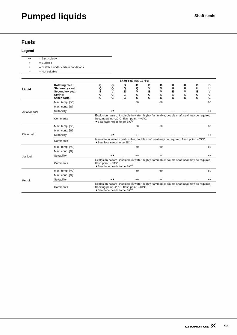
Pumped liquids Shaft seals
FuelsLegend
++ = Best solution+ = Suitable± = Suitable under certain conditions– = Not suitable
Liquid
Shaft seal (EN 12756)Rotating face:Stationary seat:Secondary seal:Spring:Other parts:
QQEGG
QQVGG
BQEGG
BQVGG
BVEGG
BVVGG
UUEGG
UUVGG
BUEGG
BUVGG
Aviation fuel
Max. temp. [°C] 60 60 60Max. conc. [%]Suitability – + – ++ – + – – – ++
CommentsExplosion hazard; insoluble in water; highly flammable; double shaft seal may be required; freezing point –20°C; flash point: –40°C.
Seal face needs to be SiCG.
Diesel oil
Max. temp. [°C] 60 60 60Max. conc. [%]Suitability – + – ++ – + – – – ++
Comments Insoluble in water; combustible; double shaft seal may be required; flash point: +55°C.Seal face needs to be SiCG.
Jet fuel
Max. temp. [°C] 60 60 60Max. conc. [%]Suitability – + – ++ – + – – – ++
CommentsExplosion hazard; insoluble in water; highly flammable; double shaft seal may be required; flash point: +38°C.
Seal face needs to be SiCG.
Petrol
Max. temp. [°C] 60 60 60Max. conc. [%]Suitability – + – ++ – + – – – ++
CommentsExplosion hazard; insoluble in water; highly flammable; double shaft seal may be required; freezing point –20°C; flash point: –40°C.
Seal face needs to be SiCG.
53
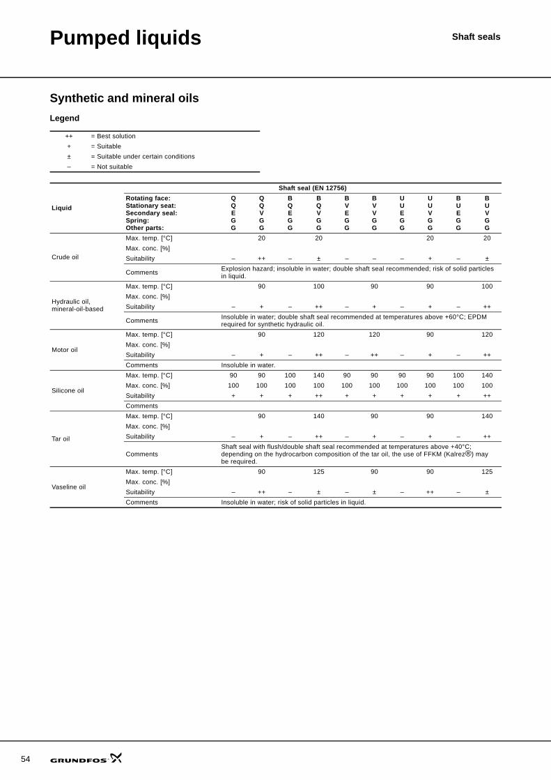
54
Pumped liquids Shaft seals
Synthetic and mineral oilsLegend
++ = Best solution+ = Suitable± = Suitable under certain conditions– = Not suitable
Liquid
Shaft seal (EN 12756)Rotating face:Stationary seat:Secondary seal:Spring:Other parts:
QQEGG
QQVGG
BQEGG
BQVGG
BVEGG
BVVGG
UUEGG
UUVGG
BUEGG
BUVGG
Crude oil
Max. temp. [°C] 20 20 20 20Max. conc. [%]Suitability – ++ – ± – – – + – ±
Comments Explosion hazard; insoluble in water; double shaft seal recommended; risk of solid particles in liquid.
Hydraulic oil, mineral-oil-based
Max. temp. [°C] 90 100 90 90 100Max. conc. [%]Suitability – + – ++ – + – + – ++
Comments Insoluble in water; double shaft seal recommended at temperatures above +60°C; EPDM required for synthetic hydraulic oil.
Motor oil
Max. temp. [°C] 90 120 120 90 120Max. conc. [%]Suitability – + – ++ – ++ – + – ++Comments Insoluble in water.
Silicone oil
Max. temp. [°C] 90 90 100 140 90 90 90 90 100 140Max. conc. [%] 100 100 100 100 100 100 100 100 100 100Suitability + + + ++ + + + + + ++Comments
Tar oil
Max. temp. [°C] 90 140 90 90 140Max. conc. [%]Suitability – + – ++ – + – + – ++
CommentsShaft seal with flush/double shaft seal recommended at temperatures above +40°C; depending on the hydrocarbon composition of the tar oil, the use of FFKM (Kalrez®) may be required.
Vaseline oil
Max. temp. [°C] 90 125 90 90 125Max. conc. [%]Suitability – ++ – ± – ± – ++ – ±Comments Insoluble in water; risk of solid particles in liquid.
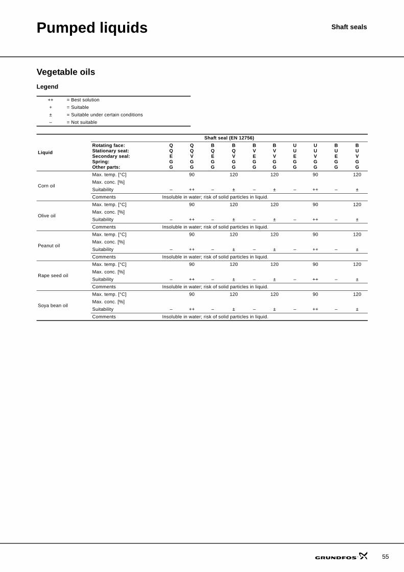
Pumped liquids Shaft seals
Vegetable oilsLegend
++ = Best solution+ = Suitable± = Suitable under certain conditions– = Not suitable
Liquid
Shaft seal (EN 12756)Rotating face:Stationary seat:Secondary seal:Spring:Other parts:
QQEGG
QQVGG
BQEGG
BQVGG
BVEGG
BVVGG
UUEGG
UUVGG
BUEGG
BUVGG
Corn oil
Max. temp. [°C] 90 120 120 90 120Max. conc. [%]Suitability – ++ – ± – ± – ++ – ±Comments Insoluble in water; risk of solid particles in liquid.
Olive oil
Max. temp. [°C] 90 120 120 90 120Max. conc. [%]Suitability – ++ – ± – ± – ++ – ±Comments Insoluble in water; risk of solid particles in liquid.
Peanut oil
Max. temp. [°C] 90 120 120 90 120Max. conc. [%]Suitability – ++ – ± – ± – ++ – ±Comments Insoluble in water; risk of solid particles in liquid.
Rape seed oil
Max. temp. [°C] 90 120 120 90 120Max. conc. [%]Suitability – ++ – ± – ± – ++ – ±Comments Insoluble in water; risk of solid particles in liquid.
Soya bean oil
Max. temp. [°C] 90 120 120 90 120Max. conc. [%]Suitability – ++ – ± – ± – ++ – ±Comments Insoluble in water; risk of solid particles in liquid.
55
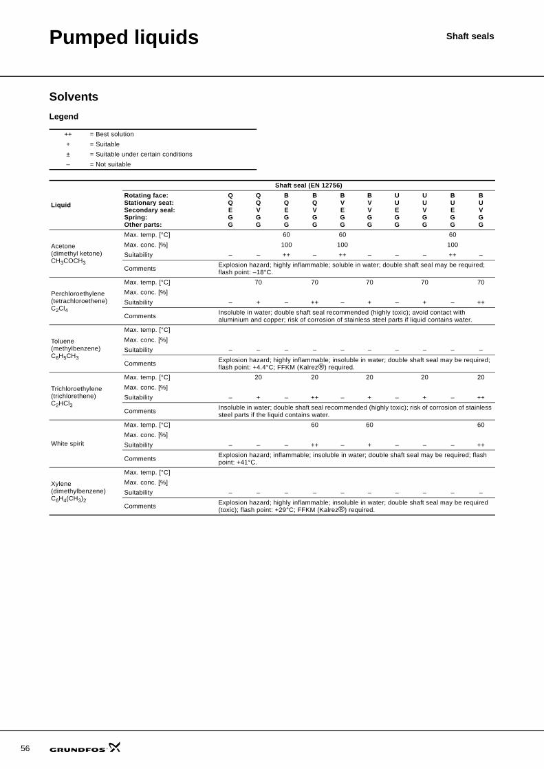
56
Pumped liquids Shaft seals
SolventsLegend
++ = Best solution+ = Suitable± = Suitable under certain conditions– = Not suitable
Liquid
Shaft seal (EN 12756)Rotating face:Stationary seat:Secondary seal:Spring:Other parts:
QQEGG
QQVGG
BQEGG
BQVGG
BVEGG
BVVGG
UUEGG
UUVGG
BUEGG
BUVGG
Acetone (dimethyl ketone)CH3COCH3
Max. temp. [°C] 60 60 60Max. conc. [%] 100 100 100Suitability – – ++ – ++ – – – ++ –
Comments Explosion hazard; highly inflammable; soluble in water; double shaft seal may be required; flash point: –18°C.
Perchloroethylene(tetrachloroethene)C2Cl4
Max. temp. [°C] 70 70 70 70 70Max. conc. [%]Suitability – + – ++ – + – + – ++
Comments Insoluble in water; double shaft seal recommended (highly toxic); avoid contact with aluminium and copper; risk of corrosion of stainless steel parts if liquid contains water.
Toluene(methylbenzene)C6H5CH3
Max. temp. [°C]Max. conc. [%]Suitability – – – – – – – – – –
Comments Explosion hazard; highly inflammable; insoluble in water; double shaft seal may be required; flash point: +4.4°C; FFKM (Kalrez®) required.
Trichloroethylene (trichlorethene)C2HCl3
Max. temp. [°C] 20 20 20 20 20Max. conc. [%]Suitability – + – ++ – + – + – ++
Comments Insoluble in water; double shaft seal recommended (highly toxic); risk of corrosion of stainless steel parts if the liquid contains water.
White spirit
Max. temp. [°C] 60 60 60Max. conc. [%]Suitability – – – ++ – + – – – ++
Comments Explosion hazard; inflammable; insoluble in water; double shaft seal may be required; flash point: +41°C.
Xylene(dimethylbenzene)C6H4(CH3)2
Max. temp. [°C]Max. conc. [%]Suitability – – – – – – – – – –
Comments Explosion hazard; highly inflammable; insoluble in water; double shaft seal may be required (toxic); flash point: +29°C; FFKM (Kalrez®) required.
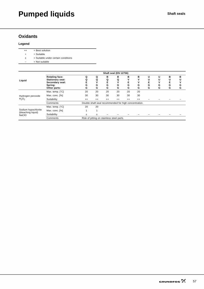
Pumped liquids Shaft seals
OxidantsLegend
++ = Best solution+ = Suitable± = Suitable under certain conditions– = Not suitable
Liquid
Shaft seal (EN 12756)Rotating face:Stationary seat:Secondary seal:Spring:Other parts:
QQEGG
QQVGG
BQEGG
BQVGG
BVEGG
BVVGG
UUEGG
UUVGG
BUEGG
BUVGG
Hydrogen peroxideH2O2
Max. temp. [°C] 20 20 20 20 20 20Max. conc. [%] 30 30 30 30 30 30Suitability ++ ++ ++ ++ ++ ++ – – – –Comments Double shaft seal recommended for high concentration.
Sodium hypochlorite(bleaching liquid)NaClO
Max. temp. [°C] 20 20Max. conc. [%] 1 1Suitability ± ± – – – – – – – –Comments Risk of pitting on stainless steel parts.
57
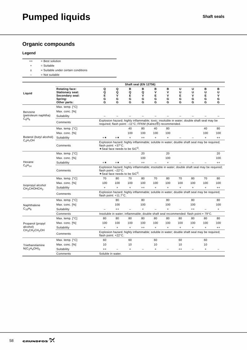
58
Pumped liquids Shaft seals
Organic compoundsLegend
++ = Best solution+ = Suitable± = Suitable under certain conditions– = Not suitable
Liquid
Shaft seal (EN 12756)Rotating face:Stationary seat:Secondary seal:Spring:Other parts:
QQEGG
QQVGG
BQEGG
BQVGG
BVEGG
BVVGG
UUEGG
UUVGG
BUEGG
BUVGG
Benzene(petroleum naphtha)C6H6
Max. temp. [°C]Max. conc. [%]Suitability – – – – – – – – – –
Comments Explosion hazard; highly inflammable; toxic; insoluble in water; double shaft seal may be required; flash point: –11°C; FFKM (Kalrez®) recommended.
Butanol (butyl alcohol)C4H7OH
Max. temp. [°C] 40 80 40 80 40 80Max. conc. [%] 100 100 100 100 100 100Suitability + + + ++ + + – – + ++
CommentsExplosion hazard; highly inflammable; soluble in water; double shaft seal may be required; flash point: +37°C.
Seal face needs to be SiCG.
HexaneC6H14
Max. temp. [°C] 20 20 20Max. conc. [%] 100 100 100Suitability + + – ++ – + – – – ++
CommentsExplosion hazard; highly inflammable; insoluble in water; double shaft seal may be required; flash point: –22°C.
Seal face needs to be SiCG.
Isopropyl alcoholCH3CHOHCH3
Max. temp. [°C] 70 80 70 80 70 80 70 80 70 80Max. conc. [%] 100 100 100 100 100 100 100 100 100 100Suitability + + + ++ + + + + + ++
Comments Explosion hazard; highly inflammable; soluble in water; double shaft seal may be required; flash point: +11.7°C.
NaphthaleneC10H8
Max. temp. [°C] 80 80 80 80 80Max. conc. [%] 100 100 100 100 100Suitability – ++ – + – + – ++ – +Comments Insoluble in water; inflammable; double shaft seal recommended: flash point:+ 79°C.
Propanol (propyl alcohol)CH3CH2CH2OH
Max. temp. [°C] 80 80 80 80 80 80 80 80 80 80Max. conc. [%] 100 100 100 100 100 100 100 100 100 100Suitability + + + ++ + + + + + ++
Comments Explosion hazard; highly inflammable; soluble in water; double shaft seal may be required; flash point: +22°C.
TriethanolamineN(C2H4OH)3
Max. temp. [°C] 60 60 60 60 60Max. conc. [%] 10 10 10 10 10Suitability ++ – + – + – ++ – + –Comments Soluble in water.
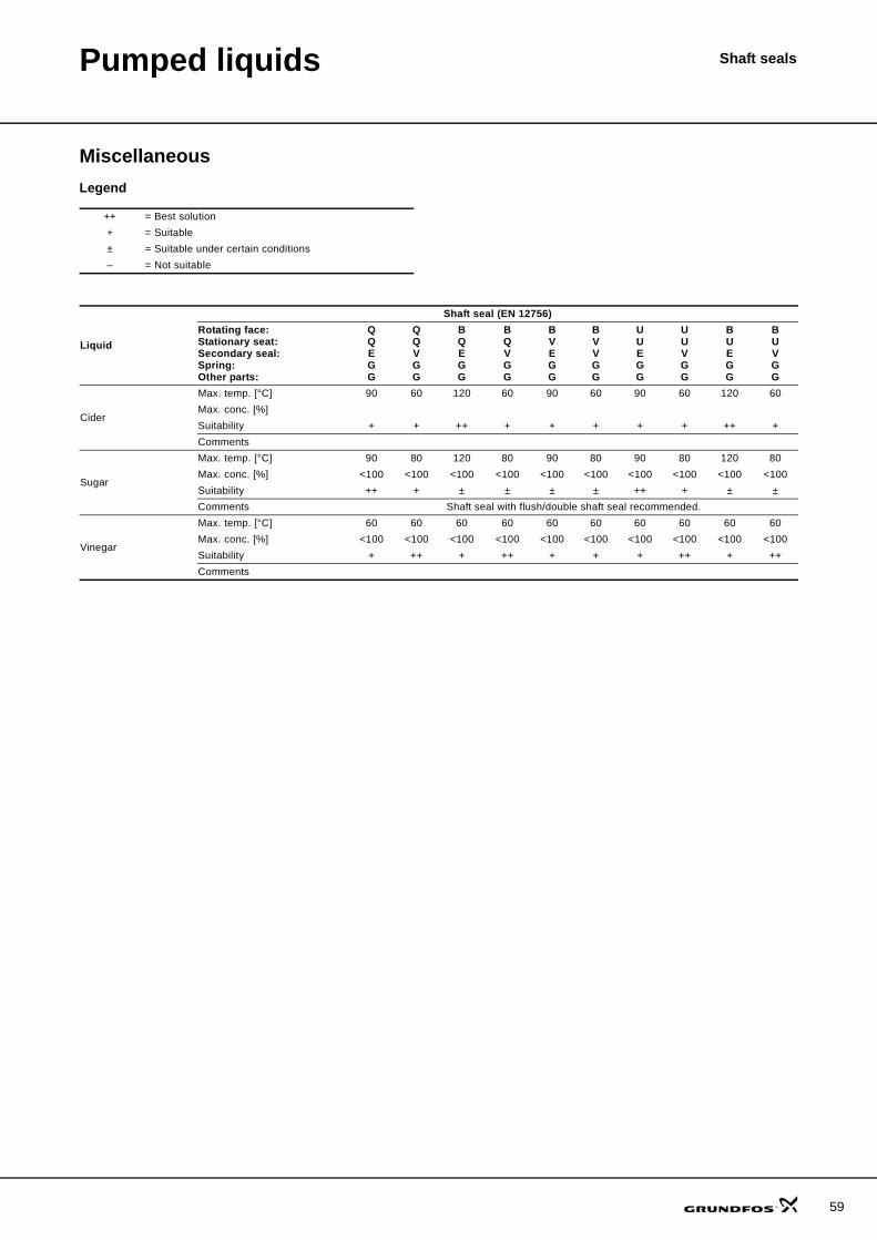
Pumped liquids Shaft seals
MiscellaneousLegend
++ = Best solution+ = Suitable± = Suitable under certain conditions– = Not suitable
Liquid
Shaft seal (EN 12756)Rotating face:Stationary seat:Secondary seal:Spring:Other parts:
QQEGG
QQVGG
BQEGG
BQVGG
BVEGG
BVVGG
UUEGG
UUVGG
BUEGG
BUVGG
Cider
Max. temp. [°C] 90 60 120 60 90 60 90 60 120 60Max. conc. [%]Suitability + + ++ + + + + + ++ +Comments
Sugar
Max. temp. [°C] 90 80 120 80 90 80 90 80 120 80Max. conc. [%] <100 <100 <100 <100 <100 <100 <100 <100 <100 <100Suitability ++ + ± ± ± ± ++ + ± ±Comments Shaft seal with flush/double shaft seal recommended.
Vinegar
Max. temp. [°C] 60 60 60 60 60 60 60 60 60 60Max. conc. [%] <100 <100 <100 <100 <100 <100 <100 <100 <100 <100Suitability + ++ + ++ + + + ++ + ++Comments
59
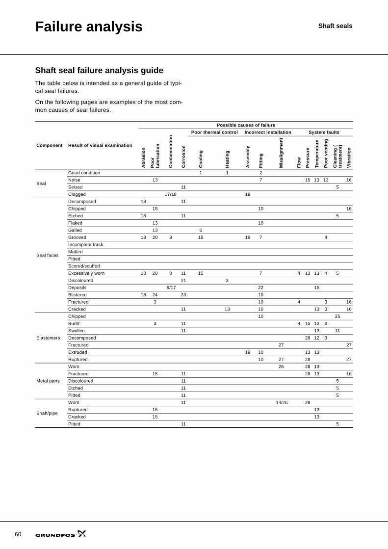
Shaft seals
60
Failure analysis
Shaft seal failure analysis guideThe table below is intended as a general guide of typi-cal seal failures.
On the following pages are examples of the most com-mon causes of seal failures.
Component Result of visual examination
Possible causes of failure
Abr
asio
n
Poor
lu
bric
atio
n
Con
tam
inat
ion
Cor
rosi
on
Poor thermal control Incorrect installation System faults
Coo
ling
Hea
ting
Ass
embl
y
Fitt
ing
Mis
alig
nmen
t
Flow
Pres
sure
Tem
pera
ture
Poor
ven
ting
Cle
anin
g (
trea
tmen
t)
Vibr
atio
n
Seal
Good condition 1 1 2Noise 13 7 15 13 13 16Seized 11 5Clogged 17/18 19
Seal faces
Decomposed 18 11Chipped 15 10 16Etched 18 11 5Flaked 13 10Galled 13 6Grooved 18 20 8 15 19 7 4Incomplete trackMattedPittedScored/scuffedExcessively worn 18 20 8 11 15 7 4 13 13 4 5Discoloured 21 3Deposits 9/17 22 15Blistered 18 24 23 10Fractured 3 10 4 3 16Cracked 11 13 10 13 3 16
Elastomers
Chipped 10 25Burnt 3 11 4 15 13 3Swollen 11 13 11Decomposed 28 12 3Fractured 27 27Extruded 19 10 13 13Ruptured 10 27 28 27
Metal parts
Worn 26 28 13Fractured 15 11 28 13 16Discoloured 11 5Etched 11 5Pitted 11 5
Shaft/pipe
Worn 11 14/26 28Ruptured 15 13Cracked 15 13Pitted 11 5
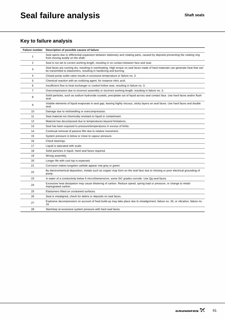
61
Shaft sealsSeal failure analysis
Key to failure analysisFailure number Description of possible causes of failure
1 Seal opens due to differential expansion between stationary and rotating parts, caused by deposits preventing the rotating ring from moving axially on the shaft.
2 Seal is not set to correct working length, resulting in no contact between face and seat.
3 Seal faces are running dry, resulting in overheating. High torque on seal faces made of hard materials can generate heat that can be transmitted to elastomers, resulting in hardening and burning.
4 Closed pump outlet valve results in excessive temperature or failure no. 3.
5 Chemical reaction with an oxidizing agent, for instance nitric acid.
6 Insufficient flow to heat exchanger or cooled hollow seat, resulting in failure no. 3.
7 Overcompression due to incorrect assembly or incorrect working length, resulting in failure no. 3.
8 Solid particles, such as sodium hydroxide crystals, precipitate out of liquid across seal contact face. Use hard faces and/or flush seal.
9 Volatile elements of liquid evaporate in seal gap, leaving highly viscous, sticky layers on seal faces. Use hard faces and double seal.
10 Damage due to mishandling or overcompression.
11 Seal material not chemically resistant to liquid or contaminant.
12 Material has decomposed due to temperatures beyond limitations.
13 Seal has been exposed to pressure/temperatures in excess of limits.
14 Continual removal of passive film due to relative movement.
15 System pressure is below or close to vapour pressure.
16 Check bearings.
17 Liquid is saturated with scale.
18 Solid particles in liquid. Hard seal faces required.
19 Wrong assembly.
20 Longer life with cool top is expected.
21 Corrosion makes tungsten carbide appear mat grey or green.
22 By electrochemical deposition, metals such as copper may form on the seal face due to missing or poor electrical grounding of pump.
23 In water of a conductivity below 5 microSiemens/cm, some SiC grades corrode. Use Qg seal faces.
24 Excessive heat dissipation may cause blistering of carbon. Reduce speed, spring load or pressure, or change to metal-impregnated carbon.
25 Elastomers fitted on uncleaned surfaces.
26 Seat is misaligned, check for debris or deposits on seal faces.
27 Explosive decompression on account of heat build-up may take place due to misalignment, failure no. 26, or vibration, failure no. 16.
28 Start/stop at excessive system pressure with hard seal faces.
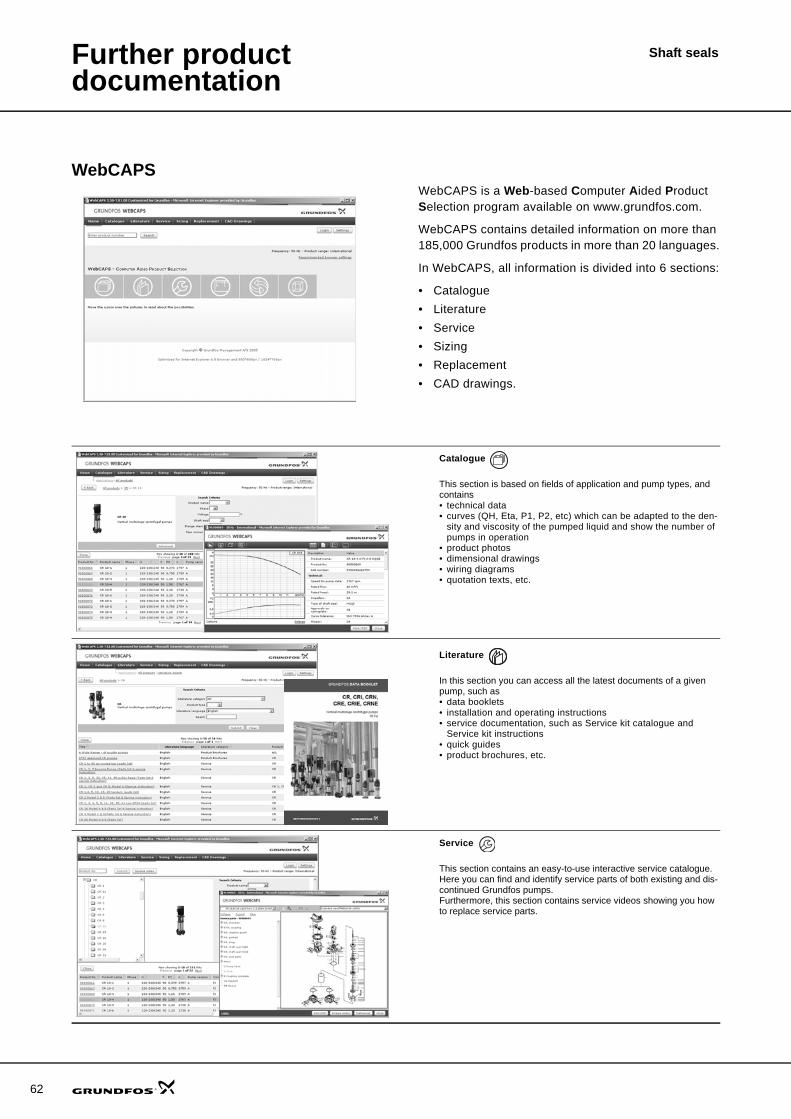
62
Shaft sealsFurther product documentation
WebCAPSWebCAPS is a Web-based Computer Aided Product Selection program available on www.grundfos.com.
WebCAPS contains detailed information on more than 185,000 Grundfos products in more than 20 languages.
In WebCAPS, all information is divided into 6 sections:
• Catalogue• Literature• Service• Sizing• Replacement• CAD drawings.
Catalogue
This section is based on fields of application and pump types, and contains • technical data• curves (QH, Eta, P1, P2, etc) which can be adapted to the den-
sity and viscosity of the pumped liquid and show the number of pumps in operation
• product photos• dimensional drawings• wiring diagrams• quotation texts, etc.
Literature
In this section you can access all the latest documents of a given pump, such as• data booklets• installation and operating instructions• service documentation, such as Service kit catalogue and
Service kit instructions• quick guides• product brochures, etc.
Service
This section contains an easy-to-use interactive service catalogue. Here you can find and identify service parts of both existing and dis-continued Grundfos pumps.Furthermore, this section contains service videos showing you how to replace service parts.
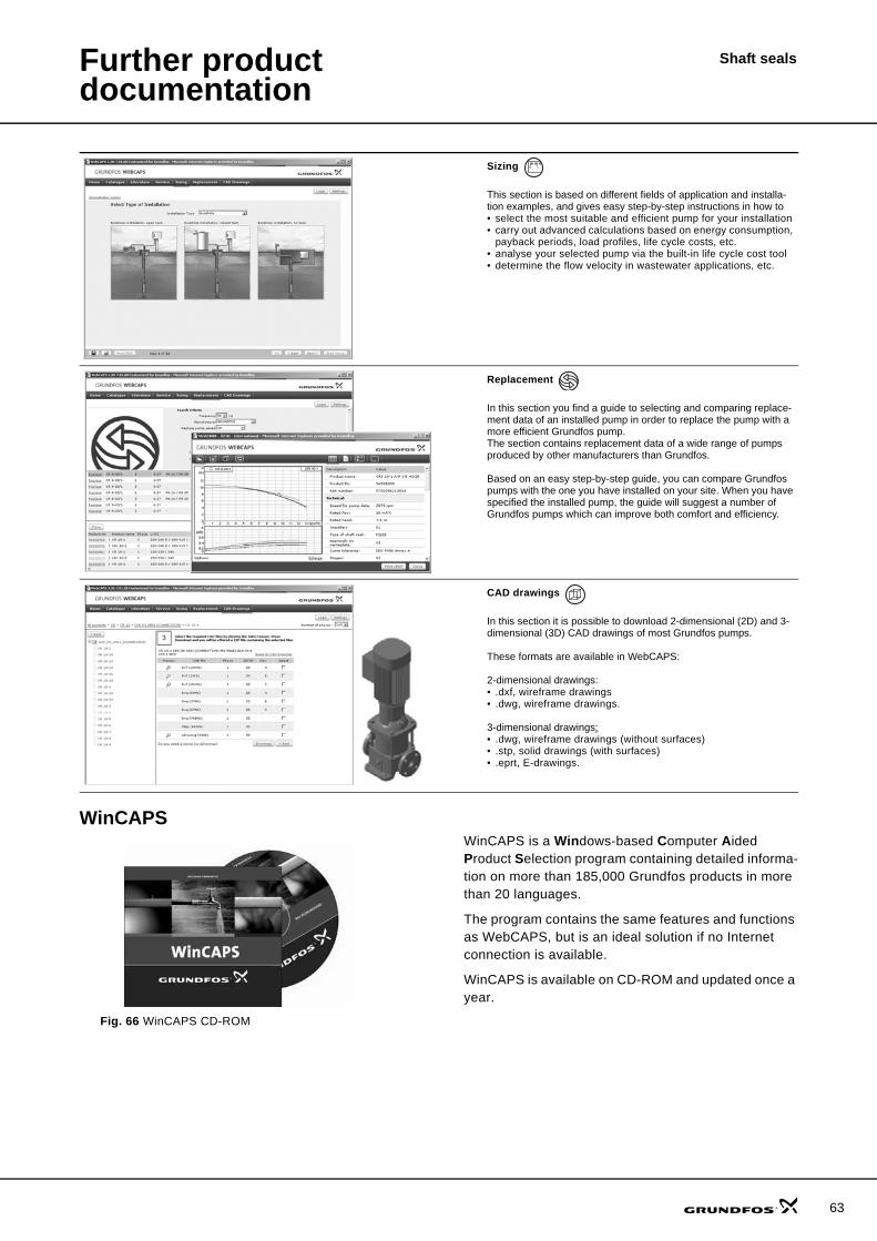
Further product documentation
Shaft seals
WinCAPS
Fig. 66 WinCAPS CD-ROM
WinCAPS is a Windows-based Computer Aided Product Selection program containing detailed informa-tion on more than 185,000 Grundfos products in more than 20 languages.
The program contains the same features and functions as WebCAPS, but is an ideal solution if no Internet connection is available.
WinCAPS is available on CD-ROM and updated once a year.
Sizing
This section is based on different fields of application and installa-tion examples, and gives easy step-by-step instructions in how to• select the most suitable and efficient pump for your installation• carry out advanced calculations based on energy consumption,
payback periods, load profiles, life cycle costs, etc.• analyse your selected pump via the built-in life cycle cost tool• determine the flow velocity in wastewater applications, etc.
Replacement
In this section you find a guide to selecting and comparing replace-ment data of an installed pump in order to replace the pump with a more efficient Grundfos pump. The section contains replacement data of a wide range of pumps produced by other manufacturers than Grundfos.
Based on an easy step-by-step guide, you can compare Grundfos pumps with the one you have installed on your site. When you have specified the installed pump, the guide will suggest a number of Grundfos pumps which can improve both comfort and efficiency.
CAD drawings
In this section it is possible to download 2-dimensional (2D) and 3-dimensional (3D) CAD drawings of most Grundfos pumps.
These formats are available in WebCAPS:
2-dimensional drawings:• .dxf, wireframe drawings• .dwg, wireframe drawings.
3-dimensional drawings:• .dwg, wireframe drawings (without surfaces)• .stp, solid drawings (with surfaces)• .eprt, E-drawings.
0 1
63
www.grundfos.com
Subject to alterations.
96519875 1006 GBRepl. 96519875 0104
Being responsible is our foundationThinking ahead makes it possible
Innovation is the essence
GRUNDFOS A/S . DK-8850 Bjerringbro . DenmarkTelephone: +45 87 50 14 00