Embed Size (px)
Citation preview

ISSN 2217-8139 (Print) UDK: 06.055.2:62-03+620.1+624.001.5(497.1)=861 ISSN 2334-0229 (Online)
2015. GODINA
LVIII
GRAĐEVINSKI MATERIJALI I
KONSTRUKCIJE
BUILDING MATERIALS AND
STRUCTURES ČA S O P I S Z A I S T R A Ž I V A N J A U O B L A S T I M A T E R I J A L A I K O N S T R U K C I J A J O U R N A L F O R R E S E A R C H OF M A T E R I A L S A N D S T R U C T U R E S
DRUŠTVO ZA ISPITIVANJE I ISTRAŽIVANJE MATERIJALA I KONSTRUKCIJA SRBIJE SOCIETY FOR MATERIALS AND STRUCTURES TESTING OF SERBIA
DDIIMMKK 2


DRUŠTVO ZА ISPITIVАNJE I ISTRАŽIVАNJE MАTERIJАLА I KONSTRUKCIJА SRBIJE S O C I E T Y F O R M А T E R I А L S А N D S T R U C T U R E S T E S T I N G O F S E R B I А
GGRRAAĐĐEEVVIINNSSKKII BBUUIILLDDIINNGG MMAATTEERRIIJJAALLII II MMААTTEERRIIААLLSS AANNDD KKOONNSSTTRRUUKKCCIIJJEE SSTTRRUUCCTTUURREESS
ČАS O P I S Z A I S T RАŽ I VАN J A U O B LАS T I MАT E R I JАLА I K O N S T R U K C I JА J O U R NАL F O R R E S EАRCH IN THE F IELD OF MАT ER IАL S АND STRUCTURES
Ш
INTERNATIONAL EDITORIAL BOARD
Professor Radomir Folić, Editor in-Chief Faculty of Technical Sciences, University of Novi Sad, Serbia
Fakultet tehničkih nauka, Univerzitet u Novom Sadu, Srbija e-mail:[email protected]
Professor Mirjana Malešev, Deputy editor Faculty of Technical Sciences, University of Novi Sad, Serbia - Fakultet tehničkih nauka, Univerzitet u Novom Sadu, Srbija, e-mail: [email protected]
Dr Ksenija Janković Institute for Testing Materials, Belgrade, Serbia Institut za ispitivanje materijala, Beograd, Srbija
Dr Jose Adam, ICITECH Department of Construction Engineering, Valencia, Spain.
Professor Radu Banchila Dep. of Civil Eng. „Politehnica“ University of Temisoara, Romania
Professor Dubravka Bjegović University of Zagreb, Faculty of Civil Engineering, Department of Materials, Zagreb, Croatia
Assoc. professor Meri Cvetkovska Faculty of Civil Eng. University "St Kiril and Metodij“, Skopje, Macedonia
Professor Michael Forde University of Edinburgh, Dep. of Environmental Eng. UK
Dr Vladimir Gocevski Hydro-Quebec, Montreal, Canada
Acad. Professor Yachko Ivanov Bulgarian Academy of Sciences, Sofia, Bulgaria
Dr. Habil. Miklos M. Ivanyi UVATERV, Budapest, Hungary
Professor Asterios Liolios Democritus University of Thrace, Faculty of Civil Eng., Greece
Professor Doncho Partov University of Construction and Architecture - VSU "LJ.Karavelov" Sofia, Bulgaria
Predrag Popović Wiss, Janney, Elstner Associates, Northbrook, Illinois, USA.
Professor Tom Schanz Ruhr University of Bochum, Germany
Professor Valeriu Stoin Dep. of Civil Eng. „Poloitehnica“ University of Temisoara, Romania
Acad. Professor Miha Tomažević, SNB and CEI, Slovenian Academy of Sciences and Arts,
Professor Mihailo Trifunac,Civil Eng. Department University of Southern California, Los Angeles, USA
Lektori za srpski jezik: Dr Miloš Zubac, profesor Aleksandra Borojev, profesor Proofreader: Prof. Jelisaveta Šafranj, Ph D Technicаl editor: Stoja Todorovic, e-mail: [email protected]
PUBLISHER
Society for Materials and Structures Testing of Serbia, 11000 Belgrade, Kneza Milosa 9 Telephone: 381 11/3242-589; e-mail:[email protected], veb sajt: www.dimk.rs
REVIEWERS: All papers were reviewed
KORICE: Budva, 1979: rušenje zidova od opeke na smicanje COVER: Budva, 1979: Brick wall failure due to shear Financial supports: Ministry of Scientific and Technological Development of the Republic of Serbia
ISSN 2217-8139 (Print ) GODINA LVIII - 2015. ISSN 2334-0229 (Online)
DRUŠTVO ZА ISPITIVАNJE I ISTRАŽIVАNJE MАTERIJАLА I KONSTRUKCIJА SRBIJE S O C I E T Y F O R M А T E R I А L S А N D S T R U C T U R E S T E S T I N G O F S E R B I А
GGRRAAĐĐEEVVIINNSSKKII BBUUIILLDDIINNGG MMAATTEERRIIJJAALLII II MMААTTEERRIIААLLSS AANNDD KKOONNSSTTRRUUKKCCIIJJEE SSTTRRUUCCTTUURREESS
ČАS O P I S Z A I S T RАŽ I VАN J A U O B LАS T I MАT E R I JАLА I K O N S T R U K C I JА J O U R NАL F O R R E S EАRCH IN THE F IELD OF MАT ER IАL S АND STRUCTURES
SАDRŽАJ Miloš ČOKIĆ Predrag PETRONIJEVIĆ Marija S. TODOROVIĆ Nenad PECIĆ ANALIZA VEZANE ENERGIJE I EMISIJE CO2 ZA IZVOĐENJE MOSTOVSKE KONSTRUKCIJE SA STANOVIŠTA ODRŽIVOSTI Originalni naučni rad ............................................... Željka RADOVANOVIĆ Sretena DIMOVSKI Ilija LALOŠEVIĆ OJAČANJE FRCM KOMPOZITIMA ZIDANIH ZIDOVA OD BLOK OPEKE Originalni naučni rad .............................................. Dragan KOSTIĆ Vuk MILOŠEVIĆ ANALIZA STABILNOSTI NEKIH IZVEDENIH KABLOVSKIH REŠETAKA Stručni rad ............................................................... Radomir FOLIĆ Danijel KUKARAS In MEMORIAM prof. dr LJUBOMIR VLAJIĆ (1941-2015) ............................................................... Uputstvo autorima ..................................................
3
21
39
59
61
CONTENTS Milos ČOKIC Predrag PETRONIJEVIC Marija S. TODOROVIC Nenad PECIC ANALYSIS OF THE EMBODIED ENERGY AND THE CO2 EMISSION IN CONSTRUCTION PROCESS OF A BRIDGE STRUCTURE FROM THE ASPECT OF SUSTAINABILITY Original scientific paper .......................................... Zeljka RADOVANOVIC Sretena DIMOVSKI Ilija LALOSEVIC STRENGTHENING MASONRY WALLS MADE OF BRICK BLOCKS WITH FRCM COMPOSITES Original scientific paper ......................................... Dragan KOSTIC Vuk MILOSEVIC STABILITY ANALYSIS OF SOME CONSTRUCTED CABLE TRUSSES Professional paper .................................................. Radomir FOLIC Danijel KUKARAS In MEMORIAM prof. dr LJUBOMIR VLAJIC (1941-2015) ............................................................ Preview report ........................................................
3
21
39
59
61

GRAĐEVINSKI MATERIJALI I KONSTRUKCIJE 58 (2015) 2 (3-20) BUILDING MATERIALS AND STRUCTURES 58 (2015) 2 (3-20)
3
ANALIZA VEZANE ENERGIJE I EMISIJE CO2 PRI IZVOĐENJU MOSTOVSKE KONSTRUKCIJE SA STANOVIŠTA ODRŽIVOSTI
ANALYSIS OF THE EMBODIED ENERGY AND THE CO2 EMISSION IN
CONSTRUCTION PROCESS OF A BRIDGE STRUCTURE FROM THE ASPECT OF SUSTAINABILITY
Miloš ČOKIĆ Predrag PETRONIJEVIĆ Marija S. TODOROVIĆ Nenad PECIĆ
ORIGINALNI NAUČNI RAD ORIGINAL SCIENTIFIC PAPER
UDK: 624.21.016doi:10.5937/grmk1502003C
1 UVOD
U radu se razmatra uticaj različitih konstruktivnihrešenja mostovskih konstrukcija na potrebnu primarnuenergiju za proizvodnju materijala i elemenatakonstrukcije i pri izvođenju konstrukcije. Takođe,analizira se uticaj ovih procesa na životnu sredinuodređivanjem odgovarajuće emisije CO2.
Kao ključni strukturni element u saobraćajnoj mreži,mostovska infrastruktura ne koristi samo brojne prirodneresurse i energiju, već ima i dug životni vek, odnosnoupotrebni ciklus, što rezultuje i velikom zabrinutošćupovodom uticaja konstrukcije na životnu sredinu.Međutim, aktuelni proces donošenja odluka i dalje seuglavnom bazira na tehničkom, sigurnosnom iekonomskom aspektu, gde procena uticaja izgradnje ieksploatacije konstrukcije na životnu sredinu još nijeintegrisana u čitav proces. Iz perspektive zaštite životnesredine, odluke donesene danas mogu imati dugoročanefekat tokom kompletnog životnog veka mosta [1].
U radu su prikazani rezultati proračuna vezaneenergije i emisije CO2 za tri rešenja mosta na istoj loka-ciji, različitih konstruktivnih sistema. Na osnovu lokacije
Miloš Čokić, master inž. građ. Doc. dr Predrag Petronijević, dipl.inž.građ, Univerzitet u Beogradu, Građevinski fakultet Prof. dr Marija S. Todorović, dipl. maš. inž, urednik Elsevier’s Energy & Buildings Journal-a, Član AINS-a, Fellow-(ASHRAE, REHVA, WAAS), Research Prof. Kyung Hee University, Seoul, Korea, Guest Prof. Southeast University, Nanjing, China Doc. dr Nenad Pecić, dipl.inž.građ, Univerzitet u Beogradu, Građevinski fakultet
1 INTRODUCTION
This paper considers the influence of different structural solutions of bridge constructions on the amount of primary energy as part of the production process of construction materials and structural elements, as well as part of construction building process. It also analyzes the impact of these processes on the environment in the form of CO2 emission.
“As the fundamental structures in the transportation network, the bridge infrastructure not only consumes numerous natural resources and energy, but also have long-term life span, which results into significant concerns of the environmental impact. However, the current decision making process is still mainly focused on the technique, safety and economic perspectives, that the environmental assessment is not yet integrated. From the environmental perspective, the decisions made today may have a long-term effect for the whole life cycle of bridge” [1].
The calculation results of the amount of embodied energy and CO2 emission for three different structural solutions of bridge construction are presented in the
Miloš Čokić, MSc Civ. Eng. Docent Predrag Petronijević, PhD Civ. Eng, University of Belgrade, Faculty of Civil Engineering Prof. Marija S. Todorović, PhD, Editor of Elsevier’s Energy & Buildings Journal, Member of AINS-a, Fellow-(ASHRAE, REHVA, WAAS), Research Prof. Kyung Hee University, Seoul, Korea, Guest Prof. Southeast University, Nanjing, China Docent Nenad Pecić, PhD Civ. Eng, University of Belgrade, Faculty of Civil Engineering

GRAĐEVINSKI MATERIJALI I KONSTRUKCIJE 58 (2015) 2 (3-20) BUILDING MATERIALS AND STRUCTURES 58 (2015) 2 (3-20)
4
mosta, karakteristika terena i projektnih zahteva,odabrana su tri sledeća konstruktivna rešenja glavnognosećeg sistema:
1) Niz prostih greda; 2) Kontinualna greda; 3) Ramovski sistem.
Kolings (Collings [2006]) izvršio je poređenje formi
mostovskih konstrukcija iz ugla uticaja na životnusredinu, na osnovu kojih su dobijeni neki pokazatelji ovezanoj energiji i emisiji CO2 kod mostova, podpretpostavkom da su ovo racionalni pokazatelji uticajakonstrukcije na životnu sredinu. Glavni rezultati iz ovogpoređenja navode nas na sledeće zaključke:
− Teret uticaja na životnu sredinu tokom izgradnjemosta je približno proporcionalan ceni konstrukcije, štoje uglavnom jednako količini materijala utrošenog zaizgradnju mostovske konstrukcije. Što je veći rasponkonstrukcije, potrebno je utrošiti i više materijala, i na tajnačin se povećava teret uticaja na životnu sredinu.Upotreba materijala s manjom količinom vezane energijei ugljen-dioksida veoma je korisna. U poređenju svećinom mostovskih konstruktivnih tipova, betonskimostovi imaju manju količinu vezane energije i emisijeCO2. Iako betonski mostovi sadrže cement, koji imavisoku količinu vezane energije, to se može ublažitizamenom dela cementa suplementima.
− U toku eksploatacije konstrukcije, postojikonstantan uticaj na životnu sredinu tokom održavanjakonstrukcije. Ovaj efekat povećava se kada se u obzir uzme i preusmeravanje saobraćaja.
− Za mostove srednjih raspona, količina emisije CO2tokom životnog veka konstrukcije od popravki iodržavanja može biti slična onim u fazi izgradnje.
Dobijeni rezultati ukazuju na to da bi održive
mostovske konstrukcije trebalo da imaju za cilj daočuvaju prirodne resurse i minimiziraju količinu otpada,odnosno štetnog uticaja (potreban je efikasan,minimalistički dizajn, koji izbegava ekstravagantnearhitektonske poduhvate), da svedu na minimum„vezanu” energiju u konstrukciji (odgovarajućimodabirom materijala i izvora materijala za funkcionalnepotrebe mosta) i da ostvare dug period eksploatacije, sminimalnim ulaganjima u održavanje konstrukcije (dugživotni vek i upotreba kvalitetnih, izdržljivih materijala)[2].
Radom je obuhvaćena analiza uslovljenostienergetskog utroška i emisije CO2 projektnim rešenjima inačinima izvođenja konstrukcije, za tri prethodnonapregnuta armiranobetonska drumska mosta.
Dobijeni rezultati treba da pokažu mogućnost da se usvajanjem određenog rešenja konstrukcije možedirektno uticati na količinu utrošenog materijala i vezaneenergije konstrukcije, pa samim tim – i na emisiju CO2.
2 OPIS PROJEKTNIH REŠENJA
Profil terena korišćen za projektovanje konstrukcije inačina izvođenja svakog od tri mosta predstavljen je naSlici 1. Potrebno je premostiti rečno korito, saobraćajnicui obostrani pad terena, sa zadatom kotom nivelete navisini od 14,00 m. Projektni maksimalni nivo vode iznosi2,90 m. Takođe, predviđena je i saobraćajnica s profilomširine 10,00 i visine 5,00 m. Lokacija je u okolini
paper. The constructions are located on the same site. Based on the location, terrain characteristics and project requirements, the following three design solutions have been chosen for the main support system:
1) Series of simple beams; 2) Continuous beam; 3) Frame. “Collings (2006) has performed an environmental
comparison of bridge forms that provides some indication of embodied energy and CO2 emissions in bridges, assuming these are a reasonable measure of the environmental burden of the structure. The major findings from that comparison suggest:
− The environmental burden during the construction of a bridge is approximately proportional to its cost, which in turn generally equates to the volume of materials consumed by the bridge. Larger spans use more material and have a higher burden. The use of materials with lower embodied energy and CO2 are beneficial. For most bridge forms the concrete bridge has the lower embodied energy and CO2 emission values. Whilst concrete bridges use cement that has a high embodied energy, this can be mitigated by the use of supplementary cementitious materials as partial cement replacement.
− There is an ongoing environmental burden during the maintenance of paintwork, bearings, joints etc., and a particular spike in that burden when resurfacing is undertaken. This is increased when traffic diversions are accounted for.
− The CO2 emissions during the life of the bridge from repair and maintenance can be similar to those of the construction phase, for bridges of moderate spans.
These findings suggest sustainable bridge
construction should aim to conserve natural resources and minimize waste (be an efficient, minimalist design, avoiding extravagant architectural statements), minimize the embodied energy in the structure (appropriate selection of materials and material sources for the functional demands of the bridge), and have a long life with minimal maintenance input (long service life and durable materials)” [2].
The study includes the analysis of conditionality of embodied energy and CO2 emission with design solutions and construction methods of three prestressed concrete road bridges.
The obtained results show that, with the selection of a specific structural design, the quantity of used construction material, energy and CO2 emission can be directly affected.
2 DESCRIPTION OF THE DESIGN SOLUTIONS
The terrain profile, on which the three bridge constructions should be located, is presented in Figure 1. The project demands bridging the river bed, road and double-sided slope of the terrain, with a given bridge grade at a height of 14.00 m. The projected water level maximum is 2.90 m, and the road profile with a width of

GRAĐEVINSKI MATERIJALI I KONSTRUKCIJE 58 (2015) 2 (3-20) BUILDING MATERIALS AND STRUCTURES 58 (2015) 2 (3-20)
5
Beograda, a predviđeni vek trajanja konstrukcije 100godina.
10.00 m and a height of 5.00 m. The location is in the vicinity of Belgrade, and the projected life cycle of the construction is 100 years.
Slika 1. Profil terena na lokaciji mosta
Figure 1. Terrain profile on the location of the bridge
Parametri zajednički za sva tri rešenja konstrukcije:
− Projekti su urađeni u skladu sa srpskim propisimai podacima dobijenim od Instituta IMS u Beogradu, [3],[4];
− Tip saobraćaja – drumski; II kategorija puta; dvetrake širine po 3,50 m, dve pešačke staze širine 1,5 m;
− Objekti se izvode na tlu nosivosti – σTla = 300 kN/m2;
− Konstrukcije su projektovane od marke betonaMB40, sa upotrebom rebraste armature RA400/500;
− Kablovi za prethodno naprezanje su od užadiØ15.2, zatezne čvrstoće fpk = 1670 N/mm2 i modula elastičnosti E = 195 kN/mm2
− Kolovoz je odvojen od pešačke staze betonskimivičnjacima, dok se na krajevima pešačkih staza nalazizaštitna ograda visine 1,40 m.
− Specifičnosti pojedinačnih rešenja konstrukcije: 1) Niz prostih greda
Glavni nosač je prethodno napregnuta armirano-betonska konstrukcija, koja se sastoji od niza prostihgreda jednakih raspona 21,2 m, s razmakom stubova od22,0 m i ukupnom dužinom od 88,0 m (Slika 2).
Glavne elemente konstrukcije čini pet armirano-betonskih stubova sa svojim temeljima, prethodnonapregnuti montažni glavni nosači, poprečni nosači,kolovozna ploča i montažni delovi pešačkih staza (Slika 3). Glavni nosači i delovi pešačkih staza su montažni,dok se ostali elementi liju na licu mesta.
Parameters common for all three structure solutions:
− The projects were developed in accordance with Serbian regulations and the data obtained from the IMS Institute in Belgrade, [3], [4];
− Traffic type − road traffic; II category; 2 lanes with 3.50 m width, 2 pedestrian paths with 1.5 m width;
− The objects are constructed on a soil with bearing capacity of - σsoil = 300 kN / m2
− The structures are constructed with the MB40 type of concrete, and with ribbed steel reinforcement bars type RA400/500;
− Prestressing cables are composed from Ø15.2 type strands, with tensile strength fpk = 1670 N/mm2 and elasticity modulus E = 195 kN/mm2
− Concrete curbs separate the road- and the pedestrian walkways; a protective fence with a height of 1.40 m is set at the end of the footpaths;
The specifics of the individual structural design solutions:
1) Series of simple beams
The main girder is a prestressed reinforced concrete
structure, which consists of a series of simple beams of equal range of 21.2 m, with distance between the pillars of 22.0 m and an overall length of 88.0 m, Figure 2.
The main elements of the construction consist of five reinforced concrete pillars and their foundations, prestressed precast main girders, cross beams, road deck and prefabricated parts of pedestrian walkways, Figure 3.
Slika 2. Poprečni presek mostovske konstrukcije – glavni nosač je niz prostih greda, (1)
Figure 2. Cross section of the bridge - main deck as a series of simple beams, (1)

GRAĐEVINSKI MATERIJALI I KONSTRUKCIJE 58 (2015) 2 (3-20) BUILDING MATERIALS AND STRUCTURES 58 (2015) 2 (3-20)
6
Glavni nosač mosta u jednom rasponu čine četiriprethodno napregnuta montažna betonska nosačasistema proste grede, „I” poprečnog preseka ikonstantne visine (Slika 3). Nosači su spregnuti kolovoznom pločom i poprečnim nosačima na krajevimai u sredini raspona.
The main girders and walkway parts are prefabri-cated, while the other elements are constructed in site.
The main bridge girder consists of 4 prestressed prefabricated concrete girders in each span that are simple beam system girders, with "I" cross-section and constant height, Figure 3. The girders are joined with road deck and cross girders at the ends and in the middle of the spans.
Slika 3. Poprečni presek konstrukcije (niz prostih greda, [1])
Figure 3. Cross section of the construction (series of simple beams, [1])
2) Kontinualni nosač
Glavni nosač je prethodno napregnuta kontinualnagreda, s rasponima 24,0 + 40,0 + 24,0 metara iukupnom dužinom od, ponovo, 88,0 m (Slika 4).
Glavne elemente konstrukcije čine četiriarmiranobetonska stuba sa svojim temeljima i prethodnonapregnuta greda sandučastog poprečnog presekakonstantne visine, sa dijafragmama nad stubovima i urasponima (Slika 4). Konstrukcija se lije na licu mesta, smontažnim delovima pešačkih staza.
Glavni nosač je prethodno napregnut sa dvanaestkablova koji se pružaju celom dužinom nosača (Slika 10). Visina glavnog nosača je konstantna i iznosi 2,20 m.
2) Continuous beam The main girder is a prestressed continuous beam
with 24.0 + 40.0 + 24.0 m spans and a total length of, again, 88.0 m, Figure 4.
The main construction elements consist of 4 reinforced concrete pillars with their foundations and prestressed beam with box cross-section of constant height, and diaphragms over the pillars and at the middle of the spans, Figure 4. The construction is cast in situ, with mounting parts of walkways.
The main girder is prestressed with 12 cables which stretch throughout the entire girder, Figure 10. The height of the main girder is constant and it values 2.20 m.
Slika 4. Poprečni presek mostovske konstrukcije – glavni nosač je kontinualna greda (2)
Figure 4. Cross section of the bridge - main deck as a continuous beam, (2)

GRAĐEVINSKI MATERIJALI I KONSTRUKCIJE 58 (2015) 2 (3-20) BUILDING MATERIALS AND STRUCTURES 58 (2015) 2 (3-20)
7
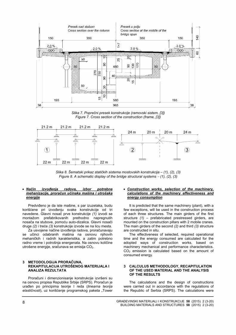
3) Ramovski sistem
Glavni nosač je prethodno napregnuta greda krutopovezana sa srednjim stubovima, s rasponima 24,0+40,0+ 24,0 metara i ukupnom dužinom od 88,0 m (Slika 5).
Glavne elemente konstrukcije čine četiriarmiranobetonska stuba sa svojim temeljima i prethodnonapregnuta greda sandučastog poprečnog presekapromenljive visine, sa dijafragmama nad stubovima i urasponima (Slika 5). Konstrukcija se lije na licu mesta, smontažnim delovima pešačkih staza.
3) Frame
The main girder is a prestressed beam, rigidly connected with the middle pillars, with 24.0 + 40.0 + 24.0 m spans and a total length of 88.0 m, Figure 5.
The main construction elements consist of 4 reinforced concrete pillars with their foundations and prestressed beam with box cross-section of varying height, and with diaphragms over the pillars and at the middle of the spans, Figure 5. The construction is cast in situ, with mounting parts of walkways.
Slika 5. Poprečni presek konstrukcije (kontinualna greda, [2])
Figure 5. Cross section of the construction (continuous beam, [2]) Greda je prethodno napregnuta s dve grupe kablova.
Osam kablova pruža se celom dužinom grede, dok suiznad središnjih stubova postavljena još po četiri kraćakabla (Slika 11).
The main girder is prestressed with two groups of cables. Eight cables are stretching throughout the whole length of the girder, and a couple of four shorter cables are placed above the central pillars, Figure 11.
Slika 6. Poprečni presek mostovske konstrukcije - konstrukcia je ramovskog sistema (3)
Figure 6. Cross section of the bridge - main deck as a frame, (3) Visina grede je promenljiva po paraboličnom zakonu
i kreće se od 1,70 m u sredini srednjeg raspona i nadosloncima ivičnih stubova, do 2,70 m nad srednjimstubovima.
The height of the main girder varies according to parabolic law, ranging from 1.70 m in the middle of mid-span and over the edge abutments, up to 2.70 m above the central piers.
GRAĐEVINSKI MATERIJALI I KONSTRUKCIJE 58 (2015) 2 (3-20) BUILDING MATERIALS AND STRUCTURES 58 (2015) 2 (3-20)
8
Slika 7. Poprečni presek konstrukcije (ramovski sistem, [3])
Figure 7. Cross section of the construction (frame, [3])
Slika 8. Šematski prikaz statičkih sistema mostovskih konstrukcija – (1), (2), (3)
Figure 8. A schematic display of the bridge structural systems − (1), (2), (3)
• Način izvođenja radova, izbor potrebnemehanizacije, proračun učinaka mašina i utrošakaenergije
Predviđeno je da iste mašine, s par izuzetaka, budu
korišćene pri izvođenju svake konstrukcije od trinavedene. Glavni nosač prve konstrukcije (1) izvodi semontažom prefabrikovanih prethodno napregnutihnosača na stubove, pomoću auto-dizalica. Glavni nosačidruge (2) i treće (3) konstrukcije izvode se na licu mesta.
Za usvojene načine izvođenja radova, proračunavajuse učinci odabranih mašina na osnovu njihovihmehaničkih i radnih karakteristika, a zatim potrebnoradno vreme i potrošnja energenata. Na osnovu količineutrošene energije, sračunava se emisija CO2.
3 METODOLOGIJA PRORAČUNA, REKAPITULACIJA UTROŠENOG MATERIJALA I ANALIZA REZULTATA
Proračuni i dimenzionisanje konstrukcije izvršeni suna osnovu propisa Republike Srbije (SRPS). Proračun jeurađen po principima teorije I reda (linearna teorijaelastičnosti), uz korišćenje programskog paketa „Tower
• Construction works, selection of the machinery, calculations of the machinery effectiveness and energy consumption
It is predicted that the same machinery (plant), with a
few exceptions, will be used in the construction process of each three structures. The main girders of the first structure (1) – prefabricated prestressed girders, are mounted on the construction pillars with 2 mobile cranes. The main girders of the second (2) and third (3) structure are constructed in situ.
The effectiveness of selected, required operational time and the energy consumed are calculated for the adopted ways of construction works, based on machinery mechanical and performance characteristics. CO2 emission is calculated based on the amount of consumed energy.
3 CALCULUS METHODOLOGY, RECAPITULATION OF THE USED MATERIAL AND THE ANALYSIS OF THE RESULTS
The calculations and the design of constructions were carried out in accordance with the regulations of the Republic of Serbia (SRPS). The calculations were

GRAĐEVINSKI MATERIJALI I KONSTRUKCIJE 58 (2015) 2 (3-20) BUILDING MATERIALS AND STRUCTURES 58 (2015) 2 (3-20)
9
6” za proračun uticaja u elementima konstrukcija.Opterećenja za čije dejstvo je izvršena analiza:
− stalno opterećenje; − saobraćajno opterećenje; − seizmičko opterećenje; − opterećenje vetrom; − temperaturni uticaji.
Nakon proračuna sve tri konstrukcije, urađen je
proračun količina materijala koji se ugrađuju u elementekonstrukcija.
Optimalni izbor građevinskih mašina ima veliki značajza uspeh investicionih projekata u građevinarstvu.Izabrane mašine moraju zadovoljavati sva tehnološkaograničenja na projektu. Cilj izbora građevinskih mašinajeste pronaći kombinaciju koja, uz sve zadate usloveograničenja, ima optimalne ekonomske parametre [5].
Mehanizacija se bira na osnovu predviđenog načinaizvođenja svake od konstrukcija i u skladu s postizanjemoptimalnih rezultata. Radovi na svakoj konstrukciji podeljeni su po pozicijama, u zavisnosti od operacijekoja se izvodi:
− prethodni i pripremni radovi; − zemljani radovi; − betonski radovi; − armirački radovi; − prethodno naprezanje; − završni radovi.
Na osnovu podataka dobijenih iz brošura
proizvođača svake od mašina (tip motora, snagamašine) i prema izračunatom broju radnih sati, pomoćupravilnika Construction Equipment Ownership andOperating Expense Schedule [6], izračunati suenergetski utrošci svake od mašina za svaku odprojektovanih konstrukcija.
• Utrošak betona i armature
1488,81338,9
1514,3
0200400600800
10001200140016001800
niz prostih greda series of simple beamskontinualna greda continuous beamramovski sistem frame
Grafik 1. Utrošak betona u zavisnosti od tipa konstrukcije
Chart 1. Quantity of concrete required, based on structure typ
made according to the principles of the First order theory (linear theory of elasticity) with the use of software package "Tower 6" for the calculation of load influences on the construction. Analyzed load cases are:
− permanent load, − traffic load, − seismic load, − wind load, − temperature influences.
After the needed structural calculations for three
bridges, the amount of the required construction material was calculated.
"The optimal choice of the construction machinery has a great importance for the success of investment projects in the construction industry. Selected machines must comply with all the technological constraints on the project. The objective of construction machinery selec-tion is to find a combination that, with all the given limi-ting conditions, has optimal economic parameters" [5].
The selection of machinery is based on predicted method of construction of the each of structures, in accordance with achieving the optimal results. The works on each structure are divided per positions, depending on the type of operation:
− preliminary and preparatory works, − terrain works, − concrete works, − steel reinforcement work, − pre-stressing, − finishing works.
Based on the data obtained from the manufacturer's
brochure for each machine (engine type, engine power) and calculated number of working hours, the energy consumption of each machine during the work on each construction is calculated, according to the "Construction Equipment Ownership and Operating Expense Schedule" [6].
• Concrete and rebar requirement
116,26114,13
146,22
020406080
100120140160
niz prostih greda series of simple beamskontinualna greda continuous beamramovski sistem frame
Grafik 2. Utrošak armature u zavisnosti od tipa konstrukcije
Chart 2. Quantity of steel rebar required, based on structure type

GRAĐEVINSKI MATERIJALI I KONSTRUKCIJE 58 (2015) 2 (3-20) BUILDING MATERIALS AND STRUCTURES 58 (2015) 2 (3-20)
10
Potrebne količine betona za svaku od tri konstrukcijeslične su i razlikuju se za nekoliko procenata. Utrošakarmature za prvu (1) i drugu (2) konstrukciju je sličan,dok je kod treće (3) dosta veći, što je posledicanaprezanja usled temperaturnih uticaja.
• Utrošak kablova za prethodno naprezanje
Pregled kablova za prethodno naprezanje:
Niz prostih greda: − Tip kablova: 9Ø15.2 − Broj kablova: 4 x 4 x 4 = 64 − Tip kotvi: S11/15 − Broj kotvi: 128
The required amounts of concrete, for each of the three constructions, are very similar and differ by a few percent. Required amount of reinforcement bars for the first (1) and second (2) structure is similar, but a lot higher for the third (3), as a result of stress due to temperature effects.
• Prestressing cables requirement
Overview of used prestressing cables:
Series of simple beams: − Cables type: 9Ø15.2 − Number of cables: 4 x 4 x 4 = 64 − Anchors type: S11/15 − Number of anchors: 128
Slika 9. Trasa rezultantnih kablova, (1)
Figure 9. Prestressing cables resultant route, (1)
Kontinualni nosač: − Tip kablova: 19Ø15.2 − Broj kablova: 12 − Tip kotvi: S19/15 − Broj kotvi: 24
Continuous beam: − Cables type: 19Ø15.2 − Number of cables: 12 − Anchors type: S19/15 − Number of anchors: 24
Slika 10. Trasa rezultantnih kablova, (2)
Figure 10. Prestressing cables resultant route, (2)
Ramovski sistem: − Tip kablova: 17Ø15.2 − Broj kablova: 8 + 2 x 4 = 20 − Tip kotvi: S19/15 − Broj kotvi: 16 + 2 x 8 = 32
Frame: − Cables type: 17Ø15.2 − Number of cables: 8 + 2 x 4 = 20 − Anchors type: S19/15 − Number of anchors: 16 + 2 x 8 = 32
Slika 11. Trasa rezultantnih kablova, (3) Figure 11. Prestressing cables resultant route, (3)

GRAĐEVINSKI MATERIJALI I KONSTRUKCIJE 58 (2015) 2 (3-20) BUILDING MATERIALS AND STRUCTURES 58 (2015) 2 (3-20)
11
12814,7
20101,1
14618,5
0
5000
10000
15000
20000
25000 niz prostih greda series of simple beams
kontinualna greda continuous beam
ramovski sistem frame
Grafik 3. Ukupna dužina užadi za prethodno naprezanje
Chart 3. Total length of prestressing strands
Najveća ukupna dužina užadi u kablovima glavnog
nosača je u drugoj konstrukciji (2), a zatim slede treća(3) i prva (1) – Grafik 3.
• Utrošak kotvi i ležišta
The maximum total length of the strands of the prestressing cables of the main girder is in the second structure (2), followed by the third (3) and then the first (1), Chart 3. • Requirement of prestressing anchors and bridge
bearings
Tabela 1. Utrošak kotvi i ležišta u zavisnosti od tipa konstrukcije Table 1. Number and type of anchors and bearings depending on the type of construction
U skladu sa usvojenim rešenjima triju konstrukcija,
razlikuju se broj i tip potrebnih kotvi, kao i ležišta zaglavne nosače (Tabela 1).
4 ODABIR MEHANIZACIJE, PRORAČUN UČINAKA I RADNOG VREMENA MAŠINA, PRORAČUN UTROŠKA ENERGIJE
• Tip, model i operacija svake od mašina, kojeučestvuju u izgradnji:
− dozer CAT D6N – skidanje humusa; − utovarivač CAT 953D – utovar zemlje; − vibro ploča Wacker Neuson DPU4545He –
sabijanje tla; − bager CAT 329D L – − iskop, utovar i zatrpavanje; − kiper MERCEDES 2628 – transport; − kamion MAN TGS 41.480 8x4 BB – transport; − fabrika betona LIEBHERR Mobilmix 2.25 -–
spravljanje betonske smese; − auto mikser LIEBHERR HTM 804 – transport
betona; − pumpa za beton LIEBHERR 28 Z4 XT THP 125 –
izlivanje betona; − auto dizalica LIEBHERR LTM 1040-2.1 –
montaža glavnih nosača;
In accordance with adopted construction solutions for each structure, the quantity and type of anchors, as well as bearings for the main girders differ, Table 1.
4 SELECTION OF THE MACHINERY, CALCULA-TION OF THE EFFECTIVENESS, WORK TIME OF THE MACHINERY AND EMBODIED ENERGY CALCULATION
• Type, model, and the operation of each machine that participates in the construction:
− dozer CAT D6N – removal of topsoil; − loader CAT 953D – loading of soil; − vibratory plate Wacker Neuson DPU4545He –
soil compaction; − hydraulic excavator CAT 329D L – excavation,
loading and backfilling; − dump truck MERCEDES 2628 – transport; − truck MAN TGS 41.480 8x4 BB – transport; − mobile mixing plant LIEBHERR Mobilmix 2.25 –
preparation of concrete mixture; − truck mixer LIEBHERR HTM 804 – concrete
transport; − truck-mounted concrete pump LIEBHERR 28 Z4
XT THP 125 – outpouring of concrete; − mobile crane LIEBHERR LTM 1040-2.1 –
[ komada ] [ number of items ]
Niz prostih greda Series of simple beams
Kontinualni nosač Continuous beam
Ramovski sistem Frame
Kotve Prestressing anchors 128 24 32
Ležišta Bearings 32 8 4

GRAĐEVINSKI MATERIJALI I KONSTRUKCIJE 58 (2015) 2 (3-20) BUILDING MATERIALS AND STRUCTURES 58 (2015) 2 (3-20)
12
− pervibrator ENAR AX 48 – ugradnja betona; − auto dizalica MAEDA MC174 CRM – držanje
prese za prednaprezanje u zahtevanom položaju; − presa i pumpa za prethodno naprezanje − S - 180/PE - 180 S – utezanje kablova; − presa i pumpa za prethodno naprezanje − S - 310/PE - 300 S – utezanje kablova; − asfaltna baza LINTEC CSD 2500 – spravljanje
asfalta; − finišer CAT AP500E – razastiranje asfalta; − teški valjak BOMAG BW 203 AD-4 – zbijanje
asfalta; − srednje teški valjak BOMAG BW 161 AD-4 –
zatvaranje gornje površine asfalta i − laki valjak BOMAG BW 151 AD-5 – peglanje
gornje površine asfalta. Za sva tri slučaja – (1), (2), (3) – usvojena su ista
rastojanja od gradilišta do objekata za dopremanjepotrebnog materijala, na osnovu čega su računati učincimašina, radno vreme i utrošak energije.
Proračun radnog vremena mašina izveden je izpotrebnih količina materijala za izgradnju svakekonstrukcije, izabranih mašina i njihovih učinaka. Zaproračun utroška energenata korišćeni su američkistandardi – Construction Equipment Ownership andOperating Expense Schedule [6].
• Proračun vezane energije:
Vezana energija predstavlja ukupnu količinuenergije, utrošenu u nekom proizvodnom procesu,odnosno ukupnu količinu energije ugrađene u finalniproizvod.
Ono što se može zaključiti iz proračuna jeste da serazlike u potrošnji energije koju koristi mehanizacija, pre svega, primećuju kod kamiona i kipera, kao i auto-miksera, odnosno transportnih mašina, čija je potrošnjaenergije direktno uslovljena tipom motora, rastojanjemgradilišta od objekata odakle se doprema materijal, kao ikoličinom materijala koji se prevozi. Kako su parametrikoji se odnose na karakteristike motora mašina, kao iudaljenost gradilišta od objekata iz kojih se prevozimaterijal isti za sva tri slučaja, razlika u potrošnji energijedirektno je uslovljena količinom transportovanogmaterijala. Pretpostavljene transportne dužine pojedinihstavki date su u Tabeli 2.
Potrošnja primarne energije po proizvedenoj toniarmature u elektrolučnoj peći prikazana je na Grafiku 4.Ovaj podatak preuzet je iz publikacije CO2 emissions ofthe Swedish steel industry .[7]
Vrednosti energije utrošene pri proizvodnji betona iasfalta preuzete su iz dva izveštaja kanadskog InstitutaAtina (Athena Sustainable Materials Institute). Preuzetisu rezultati energetskog utroška za proizvodnju betonačije karakteristike najviše odgovaraju karakteristikamabetona marke MB 40 po SRPS-u, [8], Grafik 4. Za asfaltje korišćena vrednost utroška primarne energije zamešavinu bez udela recikliranog materijala, [9] – Grafik 4.
mounting of main girders; − concrete vibrator ENAR AX 48 – compaction of
concrete; − mini crane MAEDA MC174 CRM – holding the
prestressing presses in the required position; − the press and prestressing pump S - 180/PE -
180S – prestressing of cables; − the press and prestressing pump S - 310/PE -
300S – prestressing of cables; − asphalt mixing plant LINTEC CSD 2500 – asphalt
mixing; − paver CAT AP500E – spreading of the asphalt; − heavy roller BOMAG BW 203 AD-4 – compaction
of asphalt; − medium roller BOMAG BW 161 AD-4 – closing of
the top surface of asphalt and − light roller BOMAG BW 151 AD-5 – ironing of the
top surface of asphalt.
In all three cases (1), (2), (3), the same distance from the construction site to the materials supplying facilities have been adopted. On that basis – the effectiveness of the machines, their operating time and the energy consumption were calculated. The calculation of the working time of the machinery has been derived from the required quantities of construction materials for each construction, selected machinery characteristics and their effectiveness. For the calculation of consumed energy American standards “Construction Equipment Ownership and Operating Expense Schedule” [6], were used. • Calculation of the embodied energy:
Embodied energy represents a total amount of
energy consumed in a production process, i.e. a total amount of energy embedded in a final product.
According to the calculations it can be concluded that the differences in energy consumption used by the machinery, are primarily noticed at trucks and dump trucks, and mobile-mixer, i.e. transport machinery. Their energy consumption is directly conditioned by the type of their engines, the distance between the construction site and materials supplying facilities, and the quantity of the materials being transported. Since the parameters rela-ted to the machinery engine characteristics, as well as the distance between construction site and the supplyingobjects are the same in all three cases, the difference in energy consumption is directly conditioned by the amount of transported material. Presumed transport lengths of particular processes are provided in Table 2
Consumption of primary energy per tone produced rebar in the electric arc furnace is shown in Chart 4. This data was taken from the publication "CO2 emissions of the Swedish steel industry." [7]
The values of the energy consumed for production of concrete and asphalt are taken from the two reports from the Canadian Athena Institute of (Athena Sustainable Materials Institute). Those values represent the energy, consumed in the production process of concrete whose characteristics correspond the most to the characteristics of concrete, MB 40 according to SRPS, [8] Chart 4. Also, a value of primary energy consumed for the production of asphalt mix without the share of recycled material was used, [9], Chart 4.

GRAĐEVINSKI MATERIJALI I KONSTRUKCIJE 58 (2015) 2 (3-20) BUILDING MATERIALS AND STRUCTURES 58 (2015) 2 (3-20)
13
Tabela 2. Rastojanje između gradilišta i objekata za snabdevanje građevinskim materijalima i elementima konstrukcije Table 2. The distance between construction site and objects for supplying building materials and construction elements
Lokacija objekta Lokation of object
Udaljenost od gradilišta Distance from the site [km]
Manevrisanje na gradilištu On site maneuvering ≈ 0.06
Armaturni pogon Rebar bending 10
Doprema kablova za prethodno naprezanje Prestressing cables shiping 25
Nabavka hidroizolacije Waterproofing delivery 7
Prefabrikacija betonskih ivičnjaka Prefabrication of concrete curbs 20
Nabavka bravarije Metalwork supply 17
Nabavka odvodnih cevi Drain pipes supply 12
Asfaltna baza Asphalt mixing plant 9
Tabela 3. Ukupan utrošak energenata za mehanizaciju Table 3. Total energy consumption of mechanization
Potrošnja energenata Energy consumption
Niz prostih greda Series of simple beams
Kontinualni nosač Continuous beam
Ramovski sistem Frame
Električna energija Electric energy [ kWh ] 1.667,50 1.557,26 1.730,17
Benzin Gasoline [ l ] 28,43 12,44 11,85
Dizel Diesel [ l ] 15.123,20 12.226,51 14.081,01
Ukupno Total [ kWh ] 95.784,60 77.524,13 89.235,41
11,80
0,80
3,46
0
2
4
6
8
10
12
14
armatura steel rebar
beton concrete
asfalt asphalt
Grafik 4. Vezana energija ugrađenih materijala Chart 4. Embodied energy of embedded materials,
[GJ/t], [7], [8], [9]
95785
7752489235
0
20000
40000
60000
80000
100000
120000
niz prostih greda series of simple beamskontinualna greda continuous beam
Grafik 5. Ukupan energetski utrošak mehanizacije Chart 5. Total energy consumption of the machinery
[kWh] Količina energetskog utroška po toni proizvedenog
betona višestruko je manja od količine energije utrošenepo toni proizvedenih armature i asfalta, što će se odrazitina dobijene rezultate.
The amount of energy consumption per tone of concrete is several times smaller than the amount of consumed energy per tone of steel rebar and asphalt,which will be reflected in the obtained results.

GRAĐEVINSKI MATERIJALI I KONSTRUKCIJE 58 (2015) 2 (3-20) BUILDING MATERIALS AND STRUCTURES 58 (2015) 2 (3-20)
14
Zbog masenog udela ugrađenih materijala, najvećakoličina energije će biti utrošena pri proizvodnji betona,što se može i videti na Graficima 6. i 7. Na Grafiku 5.prikazan je energetski utrošak mehanizacije, koji jenajmanji za drugu konstrukciju (2).
Međutim, energetski utrošak mehanizacije je priličnomali u poređenju sa energetskim utroškom za beton,čelik i asfalt. Samim tim, količina vezane energije odmehanizacije dosta je mala u poređenju sa ukupnomvrednošću.
Na Graficima 6. i 7. vidi se uticaj količine betonaugrađenog u konstrukciju, na odnos svakog procesa uukupnoj količini vezane energije.
Sve tri konstrukcije su prethodno napregnuti betonskimostovi, s dominantnim udelom betona u zapreminskomi masenom odnosu ugrađenih materijala. Samim tim,relevantna jedinica, po kojoj će biti izvršena analizarezultata, biće kubni metar betona.
Due to the mass fraction of the incorporated mate-rials, the largest amounts of energy consumption will be in the production of concrete, as can be seen at the Charts 6. and 7. Chart 5. shows the energy consumption of the machinery, which is the smallest for the second structure (2).
However, the energy consumption of the machinery is quite small, compared to the energy consumption for concrete, steel and asphalt production process. There-fore, the amount of embodied energy from the machi-nery will be quite small in comparison with the total value.
Charts 6. and 7. show the impact of quantity of concrete embedded in the structure, to each process ratio in the total amount of embodied energy.
All three structures are prestressed concrete bridges, with a dominant percentage of concrete in the volume and mass ratio of all used materials. Therefore, the relevant unit, per which the analysis of the results will be done, is going to be a cubic meter of concrete.
Tabela 4. Ukupna količina vezane energije Table 4. Total amount of embodied energy
Ukupna količina energije
Total energy amount [ MWh ] Niz prostih greda
Series of simple beams Kontinualni nosač Continuous beam
Ramovski sistem Frame
Mehanizacija Construction machinery 95,78 77,52 89,24
Proizvodnja armature Steel rebar production 381,07 374,10 479,28
Proizvodnja betona Concrete production 827,13 743,82 841,26
Proizvodnja asfalta Asphalt production 92,23 92,23 92,23
Ukupno Total 1.396,21 1.287,67 1.502,00
0
100
200
300
400
500
600
700
800
900
niz prostih greda series of simple beams
kontinualna greda continuous beam
ramovski sistem frame
95,7
8
77,5
2
89,2
4
381,
07
374,
10 479,
28
827,
13
743,
82
841,
26
92,2
3
92,2
3
92,2
3
[ MWh ]
Mehanizacija Construction machinery
Proizvodnja armature Rebar productionProizvodnja betona Concrete productionProizvodnja asfalta Asphalt production
Grafik 6. Ukupna količina vezane energije po procesu
Chart 6. Total amount of embodied energy per production process

GRAĐEVINSKI MATERIJALI I KONSTRUKCIJE 58 (2015) 2 (3-20) BUILDING MATERIALS AND STRUCTURES 58 (2015) 2 (3-20)
15
6.86%6.02%5.94%
27.29%29.05%31.91%
59.24%57.76%56.01%
6.61%7.16%6.14%
Niz prostih greda / Kontinualna greda / Ramovski sistem
Series of simple beams / Continuous beam / Fram
Mehanizacija Construction machinery
Proizvodnja armature Rebar production
Proizvodnja betona Concrete production
Proizvodnja asfalta Asphalt production
Grafik 7. Udeo u količini vezane energije po procesu
Chart 7. Proportional share in total embodied energy amount, per process
Grafik 8. prikazuje odnos ukupne količine vezaneenergije sve tri konstrukcije, kao i vezanu energijuprojektovanu na jedan kubni metar betona. Razlike uukupnoj količini utrošene energije u poređenju snajpovoljnijim slučajem – što je drugo konstruktivnorešenje (2) – iznose približno 10% više u odnosu na prvo(1), odnosno 15% više energije u odnosu na trećerešenje (3).
Razlika u količini vezane energije, po kubnom metrubetona ugrađenog u konstrukciju, u odnosu na drugukonstrukciju (2) iznosi približno 2,5% manje za prvo(1),odnosno približno 3% više za treće rešenje (3).
Pri približnom međusobnom odnosu betona,armature i asfalta u sva tri rešenja i pri upotrebi istog tipamehanizacije, ukupna količina vezane energije najviše bivarirala u zavisnosti od količine betona i armatureugrađenih u konstrukciju.
Najmanja količina vezane energije po m3 betona jeste u prvoj konstrukciji (1), ali to ne rezultuje i najmanjom ukupnom količinom vezane energije u prvojkonstrukciji (1), nego u drugoj (2), što je posledicarazličite količine utrošenog materijala, u zavisnosti odkonstrukcije (Grafik 8).
Chart 8. displays the ratio of total amounts of embodied energy for all three constructions, as well as the total amounts of embodied energy per one cubic meter of concrete. The differences in the total amount of used energy, when compared with the most favourable case, which is the 2nd structural solution (2), are approximately 10% more for the first (1), and 15% more energy used for the third solution (3).
The difference in the amount embodied energy per cubic meter of concrete, embedded into structure, compared to other structure (2) is approximately 2.5% less for first (1), and approximately 3% more for third solution (3).
At an approximate mutual relation of concrete, rebar and asphalt in all three solutions and with the use of the same type of machinery, the total amount of embodied energy vary the most depending on the amount of concrete and steel rebar, embedded in the structure.
The smallest amount of embodied energy per m3 of concrete is in the first structure (1), but it does not result in the lowest total amount of embodied energy in first solution (1), but in second (2), which is the result of different material quantities used for each structure, Chart 8.
1396,21
937,79
1287,67
961,76
1502,00
991,90
0
200
400
600
800
1000
1200
1400
1600
[ MWh ] [ kWh/m3 betona / kWh/m3 of concrete]
niz prostih greda series of simple beams
kontinualni sistem continuous beam
ramovski sistem frame
Grafik 8. Ukupna količina vezane energije Chart 8. Total amount of embodied energy

GRAĐEVINSKI MATERIJALI I KONSTRUKCIJE 58 (2015) 2 (3-20) BUILDING MATERIALS AND STRUCTURES 58 (2015) 2 (3-20)
16
5 EMISIJA CO2 KAO NUSPRODUKT ENERGETSKOG UTROŠKA
Za proračun emisije CO2 od mehanizacije, korišćenesu vrednosti koje prikazuju prosečnu emisiju CO2 na teritoriji Srbije [10], u zavisnosti tipa energenta koji sekoristi za rad mašine:
− električna energija: 0,71779 − benzin: 2,3035 − dizel: 2,6256
Proizvodnja čelika zasniva se na korišćenju
proizvoda na bazi uglja, a posledica toga jeste emisijavelike količine CO2. Emisija CO2 po proizvedenoj toniarmature u elektrolučnoj peći, prikazana je na Grafiku 9[7].
Vrednosti emisije CO2 pri proizvodnji betona i asfaltasu preuzete iz dva izveštaja kanadskog Instituta Atina(Athena Sustainable Materials Institute). Preuzete suvrednosti emisije CO2 pri proizvodnji betona, čijekarakteristike najviše odgovaraju karakteristikamabetona marke MB 40 po SRPS-u, [8], Grafik 9. Za asfaltje korišćena vrednost emisije CO2 za mešavinu bezudela recikliranog materijala, [9] – Grafik 9.
Proračun emisije CO2 od mehanizacije, na osnovu utrošene energije, učinjen je na osnovu podatakaInternacionalne Agencije za Energiju (IEA – InternationalEnergy Agency [11] ).
Na Grafiku 10. data je vrednost emisije ugljen-dioksida pri upotrebi mehanizacije. Vidi se da se zadržaopribližan odnos među konstrukcijskim rešenjima, kao ina Grafiku 5, kao i direktna uslovljenost emisije CO2količinom utrošene energije u slučaju upotrebemehanizacije.
590
12064,5
0
100
200
300
400
500
600
700 kg CO2 / t armature of steel rebarkg CO2 / t betona of concretekg CO2 / t asfalta of asphalt
Grafik 9. Emisija CO2 po toni proizvedenog materijala Chart 9. CO2 emission per tonne of construction
material, [7], [8], [9]
UTabeli 5. i na Graficima 11. i 12, primetno je da je –kao i u slučaju analize vezane energije – dominantnakoličina CO2 emitovana u procesu proizvodnje betona,kao najzastupljenijeg materijala u sve tri konstrukcije.
5 CO2 EMISSION AS A BYPRODUCT OF ENERGY CONSUMPTION
To calculate CO2 emission from the machinery, the values that show the average CO2 emissions on the territory of Republic of Serbia were used [10], depending on the type of energy used to operate the machine:
− electrical energy: 0,71779 − gasoline: 2,3035 − diesel: 2,6256 Production of steel is based on the use of coal
products, which results in the emission of large amounts of CO2. CO2 emissions per tone of steel rebar produced in electric arc furnace are shown in Chart 9 [7].
The data that represent CO2 emissions from the production process of concrete and asphalt are taken from two reports of the Canadian Athena Sustainable Materials Institute. The values of CO2 emissions in concrete production, whose characteristics correspond the most with the characteristics of concrete, MB 40 according to SRPS, are used, [8], Chart 9. CO2 emission data from the asphalt production is taken for a mixture without the share of recycled material, [9], Chart 9.
Calculation of CO2 emission of machinery, based on its energy consumption was made based on the data of the IEA (International Energy Agency) [11].
Chart 10. displays the value of carbon dioxide emission from the use of machinery. The ratio of CO2emission between the structural solutions remained similar, like on the Chart 5. and the direct conditionality between CO2 emission and the amount of energy consumption by the machinery can be seen.
40,97
33,2538,24
0
10
20
30
40
50niz prostih greda series of simple beamskontinualna greda continuous beamramovski sistem frame
Grafik 10. Ukupna emisija CO2 od mehanizacije Chart 10. Total CO2 emission of the machinery [ t ]
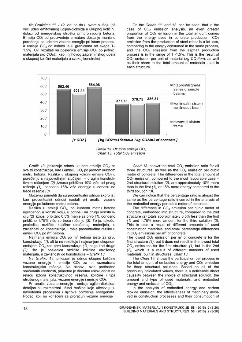
It is noticeable (Table 5. and Charts 11. and 12.)
that, as in the case of embodied energy analysis, the dominant amount of CO2 is emitted in the production process of concrete, as predominant material in all three constructions.

GRAĐEVINSKI MATERIJALI I KONSTRUKCIJE 58 (2015) 2 (3-20) BUILDING MATERIALS AND STRUCTURES 58 (2015) 2 (3-20)
17
Tabela 5. Ukupna emisija CO2 Table 5. Total CO2 emission
Ukupna emisija CO2 Total emission of CO2 [ t ]
Niz prostih greda Series of simple beams
Kontinualni nosač Continuous beam
Ramovski sistem Frame
Mehanizacija Construction machinery 40.97 33.25 38.24
Proizvodnja armature Steel rebar production 68.59 67.34 86.27
Proizvodnja betona Concrete production 446.65 401.66 454.28
Proizvodnja asfalta Asphalt production 6.19 6.19 6.19
Ukupno Total 562.40 508.44 584.98
050
100150200250300350400450500
niz prostih greda series of simple beams
kontinualna greda continuous beam
ramovski sistem frame
40,9
7
33,2
5
38,2
468,5
9
67,3
4
86,2
7
446,
65
401,
66
454,
28
6,19
6,19
6,19
[ t ]
Mehanizacija Construction machinery
Proizvodnja armature Rebar productionProizvodnja betona Concrete productionProizvodnja asfalta Asphalt production
Grafik 11. Ukupna emisija CO2 po procesu Chart 11. Total CO2 emission per process
7.28%6.54%6.54%
12.20%13.24%14.75%
79.42%79.00%77.66%
1.10%1.22%1.06%
Niz prostih greda / Kontinualna greda / Ramovski sistem
Series of simple beams / Continuous beam / Fram
Mehanizacija Construction machinery
Proizvodnja armature Rebar production
Proizvodnja betona Concrete production
Proizvodnja asfalta Asphalt production
Grafik 12. Udeo u emisiji CO2 po procesu
Chart 12. Proportional share in total CO2 emission, per process
GRAĐEVINSKI MATERIJALI I KONSTRUKCIJE 58 (2015) 2 (3-20) BUILDING MATERIALS AND STRUCTURES 58 (2015) 2 (3-20)
18
Na Graficima 11. i 12. vidi se da u ovom slučaju jošveći udeo emitovanog ugljen-dioksida u ukupnoj količini, dolazi od energetskog utroška pri proizvodnji betona.Emisija CO2 od proizvodnje armature dosta je manja upoređenju sa udelom vezane energije pri istom procesu,a emisija CO2 od asfalta je u granicama od svega 1–1.5%. Ovi rezultati su posledica emisije CO2 po jedinicimaterijala (kg CO2/t), kao i njihovog zapreminskog udelau ukupnoj količini materijala u svakoj konstrukciji.
On the Charts 11. and 12. can be seen, that in the case of CO2 emission analysis, an even greater proportion of CO2 emission in the total amount comes from the energy used in concrete production. CO2emission from the production of steel rebar is a lot less, comparing to the energy consumed in the same process, and the CO2 emission from the asphalt production process is in the range of 1 -1.5%. This is the result of CO2 emission per unit of material (kg CO2/ton), as well as their share in the total amount of materials used in each structure.
562,40
377,75
508,44
379,75
584,98
386,31
0
100
200
300
400
500
600
700
[ t CO2 ] [ kg CO2/m3 бетона / kg CO2/m3 of concrete ]
niz prostih greda series of simple beams
kontinualni sistem continuous beam
ramovski sistem frame
Grafik 13. Ukupna emisija CO2 Chart 13. Total CO2 emission
Grafik 13. prikazuje odnos ukupne emisije CO2 za sve tri konstrukcije, kao i emisiju CO2 po jednom kubnommetru betona. Razlike u ukupnoj količini emisije CO2 u poređenju s najpovoljnijim slučajem – drugim konstruk-tivnim rešenjem (2) ,iznose približno 10% više od prvogrešenja (1), odnosno 15% više energije u odnosu natreće rešenje (3).
Možemo primetiti da su procentualni odnosi skoro istikao procentualni odnosi nastali pri analizi vezaneenergije po kubnom metru betona.
Razlika u emisiji CO2, po kubnom metru betonaugrađenog u konstrukciju, u odnosu na drugu konstruk-ciju (2) iznosi približno 0,5% manje za prvo (1), odnosnopribližno 1,75% više za treće rešenje (3). To je, takođe,posledica različite količine utrošenog materijala, uzavisnosti od konstrukcije, i male procentualne razlike uemisiji CO2 po m3 betona.
Najmanja emisija CO2 po m3 betona jeste za prvukonstrukciju (1), ali to ne rezultuje i najmanjom ukupnomemisijom CO2 kod prve konstrukcije (1), nego kod druge(2), što je posledica različite količine utrošenogmaterijala, u zavisnosti od konstrukcije – Grafik 13.
Na Grafiku 14. prikazan je odnos ukupne količinevezane energije i emisije CO2 za tri razmatranakonstrukcijska rešenja. Na osnovu svih prethodnosračunatih vrednosti, primetna je direktna uslovljenost narelaciji izbora konstruktivnog rešenja, količine i tipautrošenog materijala, vezane energije i emisije CO2.
Pri analizi vezane energije i emisije ugljen-dioksida, detaljno su razmatrani učinci mašina koje učestvuju unavedenim procesima i njihova potrošnja energenata.Podaci koji su korišćeni za proračun vezane energije i
Chart 13. shows the total CO2 emission ratio for all three structures, as well as the CO2 emission per cubic meter of concrete. The differences in the total amount of CO2 emission, compared to the most favourable case –2nd structural solution (2), are approximately 10% more than in the first (1), or 15% more energy compared to the third solution (3).
We can notice that the percentage ratio is almost the same as the percentage ratio incurred in the analysis of the embodied energy per cubic meter of concrete.
The difference in CO2 emission per cubic meter of concrete, embedded into structure, compared to the 2nd structure (2) totals approximately 0.5% less than the first (1) and 1.75% more amount for the third solution (3). This is also a result of different amounts of used construction materials, and small percentage differences in CO2 emissions per m3 of concrete. The lowest CO2 emission per m3 of concrete is for the first structure (1), but it does not result in the lowest total CO2 emissions for the first structure (1) but in the 2nd (2), which is a result of different amounts of used materials, built in structures, Chart 13.
The Chart 14. shows the participation per process in the total amount of embodied energy and CO2 emission for three structural solutions. Based on all of the previously calculated values, there is a noticeable direct causality between the choice of structural solution, the amount and type of used materials, and embodied energy and emission of CO2.
In the analysis of embodied energy and carbon dioxide emission, the effectiveness of machinery invol-ved in construction processes and their consumption of

GRAĐEVINSKI MATERIJALI I KONSTRUKCIJE 58 (2015) 2 (3-20) BUILDING MATERIALS AND STRUCTURES 58 (2015) 2 (3-20)
19
emisiju CO2 u procesima proizvodnje konstruktivnihmaterijala, korišćeni su iz navedenih izvora [7], [8], [9],[10], [11].
energy were considered in detail. The data used for the calculation of embodied energy and CO2 emissions in the production processes of construction materials, was retrieved from sources [7], [8], [9], [10], [11].
79.42 / 79.00 / 77.66
59.24 / 57.76 / 56.01
12.20 / 13.24 / 14.75
27.29 / 29.05 / 31.91
1.10 / 1.22 / 1.06
6.61 / 7.16 / 6.14
7.28 / 6.54 / 6.54
6.86 / 6.02 / 5.94
0% 20% 40% 60% 80% 100%
Ukupna emisija CO2 Total emission of CO2 [ % ]
Ukupan energetski utrošak Total energy consumption [ % ]
Niz prostih greda / Kontinualna greda / Ramovski sistem
Series of simple beams / Continuous beam / Fram
Proizvodnja betona Concrete production
Proizvodnja armature Rebar production
Proizvodnja asfalta Asphalt production
Mehanizacija Construction machinery
Grafik 14. Procentualni udeo vezane energije i emisije CO2, po procesu
Chart 14. Participation of embodied energy and CO2 emission, per process
6 ZAKLJUČCI
Analizom dobijenih rezultata, prikazana je direktnaveza između konstruktivnog rešenja, načina izvođenja,količine utrošenog materijala i vezane energije, kao iemisije CO2, odnosno uticaja na životnu sredinu.
Svaki korak proračuna uslovljen je prethodno usvojenim rešenjima i ulaznim parametrima. Izborstatičkog sistema konstrukcije direktno se odražava naoblik, dimenzije i broj konstruktivnih elemenata i količinekonstrukcionih materijala. Osim toga, trajanje radova ikoličina utrošene energije uslovljeni su odabirom i karakteristikama mehanizacije i planom izvođenjakonstrukcije. Sve to se odražava na količinu vezaneenergije objekta (mosta), na osnovu prikazanih rezultataproračuna vezane energije i emisije CO2.
U ovom radu prikazan je jedan mogući načinprocene vezane energije i emisije CO2 u procesugradnje betonskih grednih mostova, koji je baziran naproračunu količina u svim glavnim koracima realizacijekonstrukcije i obuhvata sve glavne generatore konačnogrezultata.
Razmatranje međusobne uslovljenosti glavnih koraka u projektovanju i izvođenju mostova daje uvid uto na koji se način ovi procesi odražavaju na energetskiaspekt i emisiju štetnih elemenata na našu okolinu.Prikazani rezultati omogućavaju da se bolje sagledauticaj pojedinih činilaca, ukoliko se kao dodatni kriterijumpri projektovanju uključi i ekološki aspekt.
Dati su kvantitativni rezultati vezane energije i emisijeCO2 za tri konstrukcije mosta različitih statičkih sistema iiste ukupne dužine mosta, svedeni na m3 ugrađenog betona. Prikazano je i procentualno učešće pojedinihkomponenti u ukupnom rezultatu kod svih razmatranihprimera konstrukcija. Dobijene vrednosti vezane energijeiznosile su oko 1000 kWh, a emisija ugljendioksida oko 400 kg CO2, po m3 ugrađenog betona. Direktna veza
6 CONCLUSIONS
The analysis of the obtained results shows direct correlation between the structural design, construction methods, quantity of used materials and embodied energy, as well as CO2 emission and its environmental impact.
Each step of calculation procedure is conditioned by the previously adopted solutions and input parameters. The choice of structural system directly affects the shape, dimensions and number of structural elements and the quantity of construction materials. In addition, the duration of construction works and the amount of embodied energy are conditioned by the selection and the characteristics of machinery and construction plan. Based on the presented results of calculation, the amount of embodied energy of the object (bridge) and CO2emission are consequently affected by selected solutions.
Paper presents a possible method for evaluation of embodied energy and CO2 emission in the process of construction of concrete girder bridges. The method is based on calculation of the amounts in all main steps of the construction and it includes all main generators of the final result.
Correlation of the main steps in the design and construction process of a bridge affects the energy aspect and the emission of harmful elements. Presented results enable better recognition of the impact of certain factors, when the environmental aspect is an additional criterion in the design.
Quantitative results of the embodied energy and CO2emission, for three bridge structures of different struc-tural system and equal total length of the bridge per m3
of concrete are presented. The participation of individual components in the total result, in all considered examplesof the structures is shown. The obtained values were approximately 1000 kWh of embodied energy and - ap-
GRAĐEVINSKI MATERIJALI I KONSTRUKCIJE 58 (2015) 2 (3-20) BUILDING MATERIALS AND STRUCTURES 58 (2015) 2 (3-20)
20
konstruktivnog sistema i vezane energije i emisije CO2izražava se različitim količinama ukupnih materijalapotrebnim za izgradnju mosta na određenoj lokaciji,kada se primenjuju različita konstrukcijska rešenja.
proximately 400 kg of CO2 emission per m3 of built in concrete. Direct correlation of structural system and embodied energy and CO2 emission is expressed through different total quantities of the materials necessary for the construction of bridge at a particular location, when different structural solutions are applied.
7 LITERATURA REFERENCES
[1] Guangli Du, Raid Karoumi, Environmental life cycleassessment comparison between two bridge types:reinforced concrete bridge and steel compositebridge, pg. 1, Third international conference onsustainable construction materials andtechnologies (Kyoto, Japan, August 2013)
[2] Connal, J and Berndt, M. Sustainable Bridges –300 Year Design Life for Second Gateway Bridge. Proceedings, Austroads Bridges Conference,Auckland, 2009, pp. 1-16.
[3] Aleksandar Pakvor, Radomir Folić, Dejstva nakonstrukcije – knjiga 1, izdavač: Građevinskifakultet u Beogradu, Beograd 1995.
[4] Mijat S. Trojanović, Betonski mostovi I, 1970. Beograd
[5] Predrag Petronijević, Nenad Ivanišević, DraganArizanović, Primena računarskog programaCESAD pri izboru građevinskih mašina, zbornikradova ISBN – 978-86-85073-09-0, str. 397–402, Društvo građevinskih konstruktera Srbije, 13.kongres, Zlatibor - „Čigota”, 22–24. septembar2010.
[6] ”Construction Equipment, Ownership andOperating, Expense Schedule - Region III”, U.S.
Army Corps of Engineers, EP 1110-1-8, Volume 3, November 2009
[7] Hans Sandberg, Rune Lagneborg, Birgitta Lindblad, Helén Axelsson and Lars Bentell, CO2emissions of the Swedish steel industry, Scandinavian Journal of Metallurgy 2001; 30: 420–425, Table 2
[8] Cement and structural concrete products: life cycle inventory update #2, Prepared by Athena Sustainable Materials Institute, Ottawa, Canada, 2005; Table 11.3, Table 13.5
[9] A life cycle perspective on concrete and asphalt roadways: Embodied primary energy and global warming potential, Athena Sustainable Materials Institute, Ottawa, Submitted to: Cement Association of Canada, September 2006, Table 3.3
[10] Tools for consumers and designers of solar, http://www.sunearthtools.com/ , pristupljeno podacima: 2014.
[11] International Energy Agency (IEA), http://www.iea.org , pristupljeno podacima: 2014.
REZIME
ANALIZA VEZANE ENERGIJE I EMISIJE CO2 ZA IZVOĐENJE MOSTOVSKE KONSTRUKCIJE SA STANOVIŠTA ODRŽIVOSTI
Miloš ČOKIĆ Predrag PETRONIJEVIĆ Marija S. TODOROVIĆ Nenad PECIĆ
U radu je prikazana uporedna analiza vezane ener-gije i emisije CO2 u procesu gradnje, za tri mostovskekonstrukcije. Analizirane konstrukcije su prethodnonapregnuti betonski mostovi, različitih statičkih sistema,ukupne dužine 88 metara.
Razmatrana je međusobna uslovljenost izbora kon-struktivnih rešenja, načina izvođenja konstrukcije, koli-čine utrošenog materijala, vezane energije i emisije CO2.
Dat je uvid u način na koji se glavni koraci uprojektovanju i izvođenju mostova odražavaju naenergetski utrošak i emisiju CO2, procentualno i uukupnom iznosu.
Dobijeni rezultati bi trebalo da omoguće bolje sagledavanje uticaja pojedinih faktora u procesuizvođenja mostova i njihov uticaj na životnu sredinu.
Ključne reči: Vezana energija, Emisija CO2, Mos-tovske konstrukcije, Održivost, Ekološki aspekt
SUMMАRY
ANALYSIS OF THE EMBODIED ENERGY AND THE CO2 EMISSION IN CONSTRUCTION PROCESS OF A BRIDGE STRUCTURE FROM THE ASPECT OF SUSTAINABILITY
Miloš ČOKIĆ Predrag PETRONIJEVIĆ Marija S. TODOROVIĆ Nenad PECIĆ
This paper presents a comparative analysis of embodied energy and CO2 emission, in the construction process of three bridge structures. Analyzed structures are prestressed concrete bridges with different structural systems and a total length of 88 meters.
The correlation of structural system, construction method, material quantities and embodied energy and CO2 emission were considered.
Influence of the selected solutions in main steps of design and construction on the energy consumption and the emission of CO2 is presented.
The results should provide a better understanding of the effects of certain factors, in the bridge construction process, and their impact on the environment.
Key words: Embodied energy, CO2 emission, Bridge structures, Sustainability, Environmental aspect

GRAĐEVINSKI MATERIJALI I KONSTRUKCIJE 58 (2015) 2 (21-37) BUILDING MATERIALS AND STRUCTURES 58 (2015) 2 (21-37)
21
OJAČANJE FRCM KOMPOZITIMA ZIDANIH ZIDOVA OD BLOK OPEKE
STRENGTHENING MASONRY WALLS MADE OF BRICK BLOCKS WITH FRCM COMPOSITES
Željka RADOVANOVIĆ Sretena DIMOVSKI Ilija LALOŠEVIĆ
ORIGINALNI NAUČNI RAD ORIGINAL SCIENTIFIC PAPER
UDK: 692.2:693.2doi:10.5937/grmk1502021R
1 UVOD
Zidane konstrukcije od kamena obilježavajutradicionalno građevinarstvo Crne Gore. Danas, premaslobodnoj procjeni autora, u objektima sa zidanomkonstrukcijom, zidanom od blok opeke ili rjeđe od beton-skog bloka, stanuje skoro polovina stanovnika CrneGore. Zidarija je jeftin građevinski materijal koji se tradicionalno koristi u stambenoj izgradnji i najvjero-vatnije će još dugo imati primat u odnosu na drugegrađevinske materijale. Trenutno stanje zidanih kon-strukcija u crnogorskom građevinarstvu nije ohrabrujuće.Vrlo često objekti se izvode sa elementima za zidanjeneadekvatnih fizičkomehaničkih karakteristika, kontrolamaterijala vrši se vrlo rijetko, a nadzor nad građenjemzidanih objekata po pravilu izostaje.
U razornom zemljotresu, koji je pogodio crnogorskoprimorje 15.04.1979. godine, s magnitudom 7.0 jedinica Rihterove skale, značajna razaranja zabilježena su ustarim gradskim jezgrima primorskih gradova, kao i ururalnim naseljima. Usljed dejstva zemljotresa, oštećenje veliki broj spomenika kulture, kao i brojni individualniobjekti. Mnogi javni i stambeni objekti izgrađeni od ka-mena ostali su neobnovljeni. Na osnovu iskustavastečenih nakon crnogorskog zemljotresa, ali i na osnovupodataka iznesenih u radovima objavljenim nakon zem-ljotresa koji su se dogodili u protekloj deceniji na teritoriji
Željka Radovanović, Građevinski fakultet Univerziteta Crne Gore, Džordža Vašingtona b.b, 81000 Podgorica, [email protected] Sretena Dimovski, Građevinski fakultet Univerziteta Crne Gore, Džordža Vašingtona b.b, 81000 Podgorica, [email protected] Ilija Lalošević, Arhitektonski fakultet Univerziteta Crne Gore, Džordža Vašingtona b.b, 81000 Podgorica, [email protected]
1 INTRODUCTION
Stone masonry structures mark traditional civil engineering in Montenegro. Today, according to free estimate of the author, half of Montenegro population live in buildings with masonry structures made of brick blocks and rarely from concrete blocks. Masonry is cheap material that is traditionally used in building constructions and probably it will take precedence over other building materials in a long time. Currently state of masonry structures in Montenegrin civil engineering is not encouraging. Very often the buildings are constructed with masonry units with inadequate mechanical properties, control of materials are done rarely, and supervision of masonry buildings construction cannot be done, as a rule.
In destructive earthquake, which hit Montenegrin littoral on 15 April 1979 with magnitude of 7.0 degree Richter scale, important devastation was registered in old urban cores of littoral towns and in rural settlements. Large number of cultural heritages and numerous individual objects were damaged due to earthquake actions. Numerous public and residential buildings have not been renovated. Based on the experience gained after Montenegro earthquake and based on the data which have been presented in published paper after earthquakes that happened in last decade on the terri-
Zeljka Radovanovic, University of Montenegro, Faculty of Civil Engineering, Dzordza Vasingtona b.b, 81000 Podgorica, [email protected] Sretena Dimovski, University of Montenegro, Faculty of Civil Engineering, Dzordza Vasingtona b.b, 81000 Podgorica, [email protected] Ilija Lalosevic, University of Montenegro, Faculty of Architecture, Dzordza Vasingtona b.b, 81000 Podgorica, [email protected]

GRAĐEVINSKI MATERIJALI I KONSTRUKCIJE 58 (2015) 2 (21-37) BUILDING MATERIALS AND STRUCTURES 58 (2015) 2 (21-37)
22
Italije i Turske, zaključuje se da se usljed dejstavabudućih zemljotresa najveći broj žrtava i najveći stepenšteta može očekivati u objektima sa zidanomkonstrukcijom.
Najefikasniji način da se smanji broj žrtava i ublažeefekti zemljotresa jeste ugrađivanje teorijskih i eksperimentalnih istraživanja, kao i iskustvenih saznanjao ponašanju zidanih konstrukcija za vrijeme zemljotresa,u odredbe propisa prema kojima se vrši: konstruisanje,dimenzionisanje, sanacija i održavanje konstrukcija.Motivisani ovim činjenicama, na Građevinskom fakultetuUniverziteta Crne Gore pokrenuli smo istraživanja uoblasti zidanih konstrukcija, koja se odvijaju u okvirunacionalnog istraživačkog projekta SROKO „Smanjenjeseizmičkog rizika za objekte od kamena i opeke”.
Cilj istraživanja jeste da se definišu mehaničkekarakteristike zidova od materijala koji se uobičajenokoriste za zidanje zidanih konstrukcija, ali i predvidejeftine i jednostavne metode sanacije postojećihobjekata sa zidanom konstrukcijom. Testiranja,obavljena u laboratoriji Građevinskog fakulteta, tekla suu dva pravca. Testirani su elementi za zidanje i malteriod kojih su uzorci zidova napravljeni, a potom suizvedena i testiranja serija uzoraka zidova na centričnipritisak i na smicanje. Smicanje je testirano na uzorcima na koje je sila pritiska aplicirana po dijagonali. Paralelnoje teklo ispitivanje materijala koji su dostupni na tržištu, amogu biti iskorišćeni za jednostavno vanjsko ojačavanjezidanih zidova od blok opeke.
2 ODREĐIVANJE MEHANIČKIH KARAKTERISTIKA ZIDOVA OD BLOK OPEKE
Zidarija je nehomogen i neizotropan materijal, kojiima relativno dobar kapacitet na pritisak, ali malikapacitet nosivosti na zatezanje i smicanje. Zidanekonstrukcije svrstavaju se u masivne konstruktivnesisteme s relativno velikom površinom zidova, tevertikalno opterećenje zidane konstrukcije prihvatajuobično bez većih problema. Uspješno projektovanjezidanih konstrukcija zasniva se na pravilnom definisanjumehaničkih karakteristika zidanih zidova: karakterističnečvrstoće na pritisak, modula elastičnosti, modulasmicanja, čvrstoće na klizanje i čvrstoće na smicanje,odnosno graničnih vrijednosti glavnih napona zatezanja.U okviru projekta SROKO, sprovedena su ispitivanjakarakteristične čvrstoće na pritisak, modula elastičnosti i graničnih vrijednosti glavnih napona zatezanja nauzorcima, zidovima od tri vrste elemenata za zidanje,zidanim s tri klase maltera. Pri izboru elemenata zazidanje, vodilo se računa o saznanju da se u Crnoj Gorivrlo često za zidanje nosivih zidova u objektima sazidanom konstrukcijom koriste vrste elemenata zazidanje, koji nemaju dovoljnu čvrstoću na pritisak i kojipo svojim fizičko-mehaničkim svojstvima mogu bitikorišćeni samo za zidanje pregradnih zidova ili zidanjezidova ispune u armiranobetonskim konstrukcijama.Ovakva praksa bila je naročito izražena devedesetihgodina XX veka, u periodu nametnutih ekonomskihsankcija.
Testiranja su sprovedena na uzorcima zidova koji sunapravljeni od šuplje blok opeke (dimenzija 250x120x65mm), blok opeke (dimenzija 250x190x190 mm) i
tory of Italy and Turkey, it can be concluded that due to actions of future earthquakes the large numbers of humans victims and great number of damages can be expected in buildings with masonry structures.
The most effective way to reduce the number of victims and mitigate effects of earthquakes is to carry out theoretical and experimental research, as an empirical knowledge on the behaviour of masonry structures due to earthquakes; in accordance with the provisions of regulation we did: design, dimensioning, revitalization and maintenance of structures. Motivated by these facts at the Faculty of Civil Engineering, University of Montenegro, we launched the research in the field of masonry structures which takes place in the framework of a national research project SROKO "Reducing the seismic risk for buildings made of stone and brick."
The aim of the research is to define mechanical properties of the walls made of materials which are used traditionally for construction of masonry structures and predict cheap and easy method for recovery and strengthening existing buildings with masonry structures. Testing, that were conducted in Laboratory of Faculty of Civil Engineering, were performed in two directions. The masonry units and mortars from which the walls samples were made were tested, and after that testing of series of walls samples were performed on central compression and on shear. Shear is tested on the specimens on which the compression forces have been applied on the diagonal. Testing materials that are available in the market and can be used for easy external strengthening of masonry walls made of brick blocks, has been performed in parallel.
2 DETERMINATION OF MECHANICAL PROPERTIES OF BRICK BLOCKS WALLS
Masonry is inhomogeneous and anisotropic material which has relatively good capacity on compression but small load capacity in tension and shear. Masonry structures belong to a massive structural system with relatively large surface of the walls and vertical load masonry generally accepted without much trouble. The successful design of masonry structures is based on the regular definition of the mechanical properties of masonry walls: characteristic compressive strength, elastic modulus, shear modulus, strength on the sliding and shear strength or limit values for the main tensile stress. Within the project SROKO, the tests of characteristic compressive strength, elastic modulus and limit values for the main tensile stress on the walls samples from three masonry units types made on three mortar classes are conducted. In the selection of masonry units for brickwork the following facts were taken into account: in Montenegro masonry unites which have insufficient compressive strength and can be used only for partition walls or masonry infill walls in reinforced concrete structures are used very often for building of bearing walls in the buildings with masonry structures. This practice had been especially pronounced in the nineties in the period of imposed economic sanctions.
The testing were performed on the walls samples which were made from hollow brick blocks (dimensions 250x120x65 mm), brick blocks (dimensions 250x190x190 mm) and concrete blocks (dimensions

GRAĐEVINSKI MATERIJALI I KONSTRUKCIJE 58 (2015) 2 (21-37) BUILDING MATERIALS AND STRUCTURES 58 (2015) 2 (21-37)
23
betonskog bloka (dimenzija 380x190x190 mm). U ovomradu će biti prikazani samo rezultati ispitivanja nazidovima od šuplje blok opeke i blok opeke.
Standardi iz oblasti zidanih konstrukcija dozvoljavajuda se – u nedostatku konkretnih eksperimentalnihrezultata – karakteristične čvrstoće zidanih zidova pripritisku određuju na bazi analitičkih izraza u kojima kaoosnovni parametri figurišu: srednja vrijednost čvrstoćena pritisak elementa za zidanje i vrijednosti čvrstoćemaltera na pritisak. Stoga, ovi parametri definisani su napočetku naučnoistraživačkog projekta.
2.1 Čvrstoća na pritisak elemenata za zidanje i maltera
2.1.1 Čvrstoća na pritisak elemenata za zidanje
Ispitivanje čvrstoće na pritisak elemenata za zidanjevršeno je u skladu sa standardom MEST 772-1:2011, arezultati su dati u tabeli 1. Prikazani rezultatipredstavljaju aritmetičku sredinu rezultata testiranja,dobijenih na tri testirana uzorka elemenata za zidanje.
380x190x190 mm). Only the results of tested walls made of hollow brick blocks and brick blocks will be presented in this paper.
The standards in the area of masonry structures allow that in the absence of specific experimental results, the characteristic strength of masonry walls on compression is determined based on analytical expressions in which figures the basic parameters: mean compressive strength of masonry units and mortar strength on compression. Therefore, these parameters are defined at the beginning of the research project.
2.1 Compressive strength of masonry units and mortar
2.1.1 Compressive strength of masonry units The testing of the compressive strength of masonry
units was carried out in accordance with MEST 772-1: 2011, and the results are given in table 1. The presented results represent arithmetic averages of tested results that were obtained on three tested samples of masonry units.
Tabela 1. Rezultati ispitivanja čvrstoće na pritisak elementa za zidanje Table 1. Results of strength test of masonry units on compression
Šuplja blok opeka Hollow brick block
Blok opeka Brick block
Uzorak/ Sample:
Dimenzije uzorka, [mm]: Dimensions of the masonry unit, [mm]: 250x120x65 250x190x190
Srednja vrijednost čvrstoće na pritisak, [MPa]: Average value of compressive strength, [MPa]: 6,11 6,51
2.1.2 Čvrstoća na pritisak maltera
Ispitivanje maltera sprovedeno je u skladu sastandardima: MEST EN 1015-2: 2009 (uzimanje ipriprema uzoraka za ispitivanje) i MEST EN 1015-11: 2009 (određivanje čvrstoće na pritisak i savijanje).Rezultati ispitivanja su dati u tabeli 2.
2.1.2 Compressive strength of mortar The testing of mortars was conducted according to
the following standards: MEST EN 1015-2: 2009 (sampling and preparation of samples for testing) and MEST EN 1015-11: 2009 (determination of compressive strength and tensile strength due to bending). The test results are given in table 2.
Tabela 2. Čvrstoća na pritisak maltera Table 2. Compressive strength of mortar
Produžni malter/ Cement-lime mortar: M1 M2 M3 M4
Odnos Vc:Vk:Vp Volume ratio between: cement, lime and sand 1 : 0,75 : 5 1 : 0,5 : 6 1 : 0,25 : 4,25 1 : 0,2 : 3
Srednja vrijednost čvrstoće na pritisak, [MPa]: Average value of compressive strength, [MPa] 11,60 8,20 14,40 23,90
Klasa maltera/ Class of mortar: M10-1 M5 M10-2 M20

GRAĐEVINSKI MATERIJALI I KONSTRUKCIJE 58 (2015) 2 (21-37) BUILDING MATERIALS AND STRUCTURES 58 (2015) 2 (21-37)
24
2.2 Određivanje čvrstoće na pritisak zidova i modula elastičnosti
Izvršena su testiranja s ciljem određivanja: čvrstoće na pritisak, modula elastičnosti, čvrstoće na smicanje imodula smicanja.
Za proračun i ispitivanje izabrana je kombinacijaopeke/blokova s više vrsta maltera. Šuplja opekakombinovana je s malterima klasa M5 i M10-2 (oznakana zidovima PM2 i PM3), dok su zidovi od bloka opekekombinovani s malterom klase M10-1, M10-2 i M20 (oznake na zidovima od blok opeke: IM1; IM3 i IM4).
2.2.1 Ispitivanje zidova na pritisak
Osnovni pokazatelj kvaliteta nearmiranog zidanogzida jeste karakteristična čvrstoća zida na pritisak, fk. Karakteristična čvrstoća zida na pritisak fk, jeste vrijednost čvrstoće zida, bez efekta spriječenedeformacije, vitkosti ili ekscentriciteta opterećenja, zakoju postoji propisana vjerovatnoća od 5% da ne budedostignuta, u hipotetički neograničenoj seriji ispitivanja.Karakteristična čvrstoća zida zavisi od karaktera zida,odnosno postojanja podužne malterske spojnice u zidu,vrste i grupe elemenata od kojih je zid zidan, kao i odčvrstoće na pritisak elementa za zidanje i čvrstoćemaltera na pritisak.
Ispitivanje čvrstoće na pritisak i modula elastičnostizidanih zidova od blok opeke obavljeno je na petnaesetuzoraka zidova, prema standardu EN 1052-1:2011 –„Metode ispitivanje zidanih konstrukcija – Dio 1:Određivanje čvrstoće na pritisak”.
Testiranje na pritisak sprovedeno je na zidovima od: − male opeke (dim. 25x12x6.5 cm), varirane dvije
marke maltera, ukupno šest uzoraka; − blok opeke (dim. 25x19x19 cm), varirane tri marke
maltera, ukupno devet uzoraka. Vrste ispitivanih uzoraka zidova vide se na slici 1 a).
2.2 Determination of compressive strength and elasticity modulus of masonry walls
Testing was conducted to determine: compressive strength, elastic modulus, shears strength and shear modulus.
The combinations of bricks/blocks with multiple types of mortar have been chosen for the calculation and testing. The hollow brick blocks have been combined with mortar classes: M5 and M10-2 (marks on the walls PM2 and PM3), while the walls made of brick blocks have been combined with mortar classes: M10-1, M10-2 and M20 (marks on the walls made of brick blocks: IM1; IM3 and IM4).
2.2.1 Testing of the masonry walls on compression
The main indicator of the quality of unreinforced masonry is characteristic strength of the wall on the compression, fk. The characteristic strength of the wall on the compression fk is the value of wall strength, without the effects of restraint deformation, slenderness or eccentricity of the load, for which there is a prescribed probability of 5% that is not achieved in a hypothetical unlimited series of testing. The characteristic strength of the wall depend on the character of the wall, respectively existence of longitudinal mortar joints in the wall, type and group of masonry units from which the wall is built, as well as the compressive strength of masonry units and strength of mortar on compression.
The testing of compressive strength and elasticity modulus has been performed on the 15 walls samples in accordance with the standard EN 1052-1: 2011 – “Test methods for masonry - Part 1: Determination of compressive strength”.
The testing of the walls samples on compression have been performed on the walls of:
− Small brick blocks (dim. 25x12x6.5 cm), three class of mortar were varied, total of 6 samples;
− Brick blocks (dim. 25x12x6.5 cm), three class of mortar were varied, total of 9 samples;
The types of walls that we tested can be seen in Figure 1 a).
17
10
21
1010
1
3
5
2
4
6
T1T2
T3T4
(a) Vrste zidova od blok opeke (b) Šema mjernih mjesta (a) Types of wall made of brick blocks (b) Scheme of measurement points
Slika 1. Ispitivanje zidova na pritisak Figure 1. Testing of the walls on compression
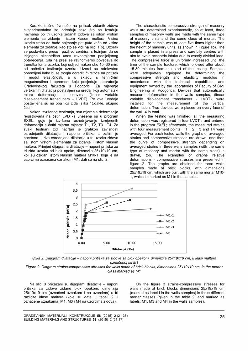
GRAĐEVINSKI MATERIJALI I KONSTRUKCIJE 58 (2015) 2 (21-37) BUILDING MATERIALS AND STRUCTURES 58 (2015) 2 (21-37)
25
Karakteristične čvrstoće na pritisak zidanih zidovaeksperimentalno se određuju tako što se izrađujunajmanje po tri uzorka zidanih zidova sa istom vrstomelementa za zidanje i istom klasom maltera. Visinauzorka treba da bude najmanje pet puta veća od visine elementa za zidanje, kao što se vidi na slici 1(b). Uzorakse postavlja u presu i pažljivo centrira, s težnjom da seizbjegne ekcentričan unos ravnomjerno podijeljenogopterećenja. Sila na presi se ravnomjerno povećava dotrenutka loma uzorka, koji uslijedi nakon oko 15–30 min. od početka testiranja uzorka. Uzorci su adekvatnoopremljeni kako bi se mogla odrediti čvrstoća na pritisaki modul elastičnosti, a u skladu s tehničkimmogućnostima i opremom koju posjeduje laboratorijaGrađevinskog fakulteta u Podgorici. Za mjerenje vertikalnih dilatacija postavljeni su uređaji koji automatskimjere deformacije u zidovima (linear variablediseplacement transducers – LVDT). Po dva uređaja postavljena su na oba lica zida (slika 1),dakle, ukupnočetiri.
Nakon izvršenog testiranja, sva mjerenja deformacijaregistrovana na četiri LVDT-a unesena su u program EXEL, gdje je izvršeno osrednjavanje izmjerenihdeformacija s četiri mjerna mjesta: T1, T2, T3 i T4. Zasvaki testirani zid nacrtan je grafikon zavisnostiosrednjenih dilatacija i napona pritiska, a zatim jenacrtana i kriva osrednjene dilatacije u tri uzorka zidovasa istom vrstom elemenata za zidanje i istom klasommaltera. Primjeri dijagrama dilatacije – naponi pritiska zatri zida uzorka od blok opeke, dimnezija 25x19x19 cm,koji su ozidani istom klasom maltera M10-1, koja je nauzorcima označena oznakom M1, dati su na slici 2.
The characteristic compressive strength of masonry walls are determined experimentally, so at least, three samples of masonry walls are made with the same type of masonry units and the same class of mortar. The height of the sample was at least five times higher than the height of masonry units, as shown in Figure 1b). The sample is placed in a press and carefully centres with aim to avoid eccentric intake due to evenly divided load. The compressive force is uniformly increased until the time of the sample fracture, which followed after about 15-30 minutes from the start of the testing. Samples were adequately equipped for determining the compressive strength and elasticity modulus in accordance with the technical capabilities and equipment owned by the laboratories of Faculty of Civil Engineering in Podgorica. Devices that automatically measure deformation in the walls samples, (linear variable displacement transducers - LVDT), were installed for the measurement of the vertical deformation. Two devices were placed on every face of the wall, 4 in total.
When the testing was finished, all the measuring deformation was registered in four LVDT's and entered in the program EXEL; afterwards, the measured strains with four measurement points: T1, T2, T3 and T4 were averaged. For each tested walls the graphs of averaged strains and compressive stresses are drawn, and then the curve of compressive strength depending on averaged strains in three walls samples (with the same type of masonry and mortar with the same class) is drawn, too. The examples of graphs relative deformations - compressive stresses are presented in figure 2. The graphs are obtained for three walls samples made of brick blocks, with dimensions 25x19x19 cm, which are built with the same mortar M10-1, which is marked as M1 in the samples.
Slika 2. Dijagram dilatacije – naponi pritiska za zidove sa blok opekom, dimenzija 25x19x19 cm, u klasi maltera
označenoj sa M1 Figure 2. Diagram strains-compressive stresses for walls made of brick blocks, dimensions 25x19x19 cm, in the mortar
class marked as M1
Na slici 3 prikazani su dijagrami dilatacije – naponi pritiska za zidove zidane blok opekom, dimenzija25x19x19 cm (označeni oznakom I na uzorcima) u trirazličite klase maltera (koje su date u tabeli 2, ioznačene oznakama: M1, M3 i M4 na uzorcima zidova).
On the figure 3 strains-compressive stresses for walls made of brick blocks dimensions 25x19x19 cm (marked as label I in the walls samples) in three different mortar classes (given in the table 2, and marked as labels: M1, M3 and M4 in the walls samples).
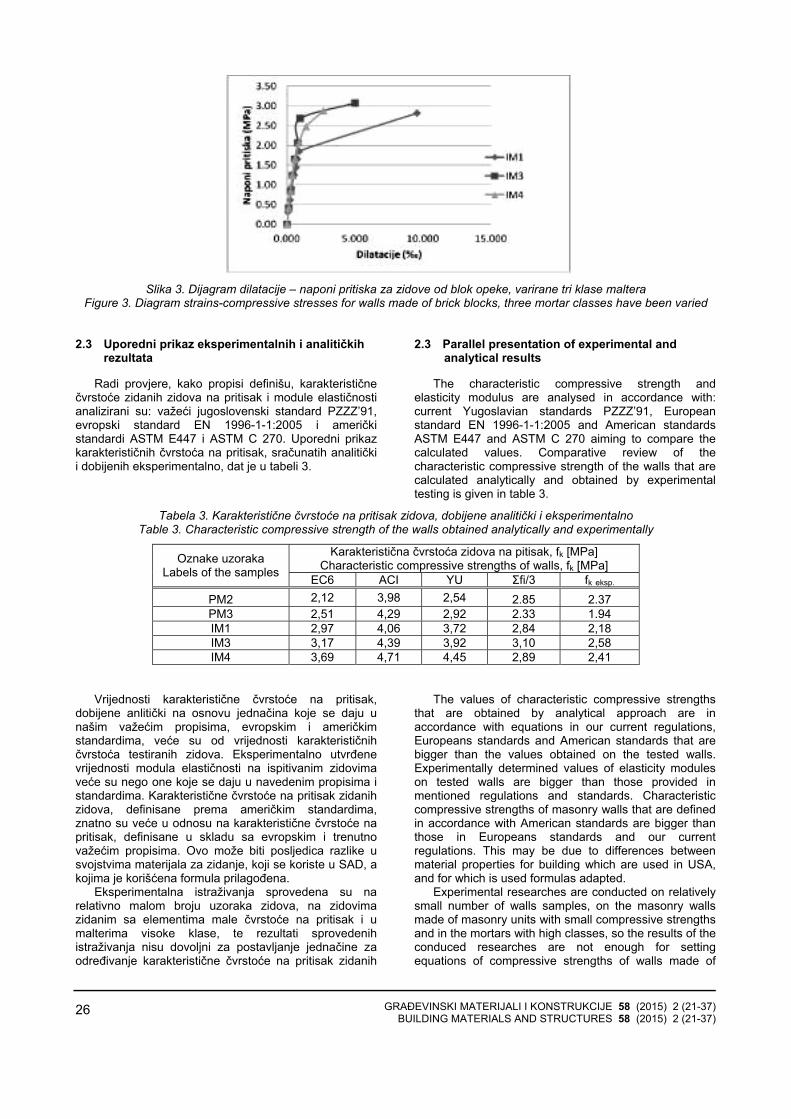
GRAĐEVINSKI MATERIJALI I KONSTRUKCIJE 58 (2015) 2 (21-37) BUILDING MATERIALS AND STRUCTURES 58 (2015) 2 (21-37)
26
Slika 3. Dijagram dilatacije – naponi pritiska za zidove od blok opeke, varirane tri klase maltera
Figure 3. Diagram strains-compressive stresses for walls made of brick blocks, three mortar classes have been varied 2.3 Uporedni prikaz eksperimentalnih i analitičkih
rezultata
Radi provjere, kako propisi definišu, karakterističnečvrstoće zidanih zidova na pritisak i module elastičnostianalizirani su: važeći jugoslovenski standard PZZZ’91,evropski standard EN 1996-1-1:2005 i američkistandardi ASTM E447 i ASTM C 270. Uporedni prikazkarakterističnih čvrstoća na pritisak, sračunatih analitičkii dobijenih eksperimentalno, dat je u tabeli 3.
2.3 Parallel presentation of experimental and analytical results
The characteristic compressive strength and elasticity modulus are analysed in accordance with: current Yugoslavian standards PZZZ’91, European standard EN 1996-1-1:2005 and American standards ASTM E447 and ASTM C 270 aiming to compare the calculated values. Comparative review of the characteristic compressive strength of the walls that are calculated analytically and obtained by experimental testing is given in table 3.
Tabela 3. Karakteristične čvrstoće na pritisak zidova, dobijene analitički i eksperimentalno Table 3. Characteristic compressive strength of the walls obtained analytically and experimentally
Karakteristična čvrstoća zidova na pitisak, fk [MPa] Characteristic compressive strengths of walls, fk [MPa] Oznake uzoraka
Labels of the samples EC6 ACI YU Σfi/3 fk eksp. PM2 2,12 3,98 2,54 2.85 2.37 PM3 2,51 4,29 2,92 2.33 1.94 IM1 2,97 4,06 3,72 2,84 2,18 IM3 3,17 4,39 3,92 3,10 2,58 IM4 3,69 4,71 4,45 2,89 2,41
Vrijednosti karakteristične čvrstoće na pritisak,dobijene anlitički na osnovu jednačina koje se daju unašim važećim propisima, evropskim i američkimstandardima, veće su od vrijednosti karakterističnihčvrstoća testiranih zidova. Eksperimentalno utvrđene vrijednosti modula elastičnosti na ispitivanim zidovimaveće su nego one koje se daju u navedenim propisima istandardima. Karakteristične čvrstoće na pritisak zidanihzidova, definisane prema američkim standardima,znatno su veće u odnosu na karakteristične čvrstoće napritisak, definisane u skladu sa evropskim i trenutnovažećim propisima. Ovo može biti posljedica razlike usvojstvima materijala za zidanje, koji se koriste u SAD, akojima je korišćena formula prilagođena.
Eksperimentalna istraživanja sprovedena su narelativno malom broju uzoraka zidova, na zidovimazidanim sa elementima male čvrstoće na pritisak i umalterima visoke klase, te rezultati sprovedenihistraživanja nisu dovoljni za postavljanje jednačine zaodređivanje karakteristične čvrstoće na pritisak zidanih
The values of characteristic compressive strengths that are obtained by analytical approach are in accordance with equations in our current regulations, Europeans standards and American standards that are bigger than the values obtained on the tested walls. Experimentally determined values of elasticity modules on tested walls are bigger than those provided in mentioned regulations and standards. Characteristic compressive strengths of masonry walls that are defined in accordance with American standards are bigger than those in Europeans standards and our current regulations. This may be due to differences between material properties for building which are used in USA, and for which is used formulas adapted.
Experimental researches are conducted on relatively small number of walls samples, on the masonry walls made of masonry units with small compressive strengths and in the mortars with high classes, so the results of the conduced researches are not enough for setting equations of compressive strengths of walls made of

GRAĐEVINSKI MATERIJALI I KONSTRUKCIJE 58 (2015) 2 (21-37) BUILDING MATERIALS AND STRUCTURES 58 (2015) 2 (21-37)
27
zidova od blok opeke. Analitički izrazi za određivanječvrstoće na pritisak zidanih zidova, dati u standardu EN1996-1-1:2005, daju vrijednosti najbliže vrijednostimakoje su utvrđene eksperimentom.
Uporedni prikaz modula elastičnosti, sračunatihanalitički i dobijenih eksperimentalno, dat je u tabeli 4.
brick blocks. Analytical expressions for determinations of characteristic compressive strengths of walls, given in standards EN 1996-1-1:2005, provide values that are nearest with experimentally obtained values.
Comparative view of elasticity modules analytically and experimentally obtained is given in the table 4.
Tabela 4. Moduli elastičnosti dobijeni analitički i eksperimentalno Table 4. Elasticity modulus obtained analytically and experimentally
Modul elastičnosti E, [GPa] Elasticity modulus E, [GPa] Oznake uzoraka
Labels of the samples EC6 ACI YU E eksp. PM2 2,12 2,79 2,54 2.63 PM3 2,51 3,00 2,92 5.40 IM1 2,97 2,84 3,72 2,88 IM3 3,17 3,07 3,92 3,07 IM4 3,69 3,30 4,45 3,19
Modul elastičnosti, dobijen eksperimentalno zauzorke zidova od blok opeke (oznaka I), iznosi oko1300xfk, što je više od propisanog načina definisanjamodula elastičnosti, koji iznosi 1000xfk.
Malter u spojnicama ne utiče samo na čvrstoću zidana pritisak, već i na ukupni mehanizam loma zida.Upotrebom maltera veće čvrstoće, u kombinaciji saelementima za zidanje male čvrstoće na pritisak,smanjuje se nosivost zidanog zida, jer zid postaje krtiji.Preporuka je ‒ izbjegavati zidanje zidova sa elementimamale čvrstoće na pritisak u malteru visoke klase.
Na osnovu do sada analiziranih rezultataeksperimenta, opaža se da povećana količina kreča urecepturi za malter popravlja duktilnost zida. Ovaj stavtreba potvrditi i dodatnim analizama.
Značajan uticaj na ponašanje zida i mehanizam lomatokom eksperimenta ima kvalitet izrade zidova uzoraka.Na čvrstoću zida na pritisak utiče i ispunjenosthorizontalnih i vertikalnih spojnica malterom. Preporukaje ugrađivanje maltera konstantne debljine duž čitavehorizontalne spojnice, kako bi naprezanje unutar zidabilo što ravnomjernije.
2.4 Određivanje čvrstoće na smicanje i modula smicanja
Seizmičke sile koje djeluju na zidane konstrukcije skrutom međuspratnom konstrukcijom, u trenutku lomaizazivaju smicanje koje karakterišu dijagonalne pukotineu zidovima u prizemlju. Ovakav mehanizam loma uvelikom broju slučajeva određuje seizmičku otpornostzidanih konstrukcija, a zbog uzroka nastanka pukotina,zove se i rušenje usljed dijagonalnog zatezanja. Na slici 4 prikazan je karakteristični mehanizam lomadijagonalnim zatezanjem, koji je registrovan na jednomobjektu u Budvi nakon dejstva razornog zemljotresa1979. godine.
Kod mehanizma smicanjem, koji karakterišenastanak kosih – dijagonalnih pukotina, pukotine su posljedica glavnih zatežućih napona koji nastaju u ravnizida, usljed kombinovanog djelovanja opterećenja napritisak i horizontalnog opterećenja u ravni zida kojeprouzrokuje smicanje. U trenutku kada glavni naponzatezanja dostigne vrijednost, koja se zove „čvrstoća
Modulus obtained experimentally for samples of walls of brick blocks (mark I) is about 1300xfk, what is higher than the elasticity modulus defined in the regulations, which is 1000xfk.
Mortar in the layers and heads joints has influenced both compressive strength of the wall and failure mechanism of the wall as well. The strengths of the walls are decreased if using mortar of higher strength in combination with masonry units with small compressive strength because the walls become brittle.
On the based experimental results that are obtained so far it can be concluded that bigger quantity of lime in the mixture of mortar improves ductility of the wall. This attitude needs to be confirmed and additionally analyzed.
The important influence on the behaviour and failure mechanism of wall during the experiment has quality of construction of the wall sample. The filling of horizontal and head joints with mortar has influenced the compressive strength of the wall. The recommendation is embedding mortar with constant thickness along the horizontal joints, which will distribute the stress inside the wall evenly.
2.4 Determination of shear strength and shear modulus
The seismic forces acting on masonry structures with rigid floor structures in the moment of structure failure cause shear which is presented by diagonal cracks on the walls on the ground floor. This failure mechanism in great number of cases determinate seismic resistance of masonry structures, and it causes cracks called demolition due to diagonal tension. The characteristics of failure mechanism with diagonal tension are presented in figure 4. It was registered on one building in Budva after the destructive earthquake in 1979.
In the shear mechanism, which is characterized by the formation of oblique - diagonal cracks, the cracks are the result of the main tensile stresses which occur in the face of the wall and they are caused by shear due to the combined effects of loading on the compression and horizontal loads that act in the plane of the wall. In the moment when main tension stress reaches the value

GRAĐEVINSKI MATERIJALI I KONSTRUKCIJE 58 (2015) 2 (21-37) BUILDING MATERIALS AND STRUCTURES 58 (2015) 2 (21-37)
28
zida na zatezanje”, u zidu nastaju pukotine udijagonalnom pravcu [6].
which is called the "strength of the wall in tension" the wall cracks in a diagonal direction, [6].
Slika 4. Budva, 1979: rušenje zidova od opeke na smicanje, [6]
Figure 4. Budva, 1979: Brick wall failure due to shear, [6]
Evropski standard za projektovanje zidanihkonstrukcija, EN 1996-1-1:2005, ne prepoznaje ovajmehanizam loma zidanih zidova i ne definiše „čvrstoću zida na zatezanje”. Brojni zidani objekti projektovani su iizvedeni u skladu s još uvijek važećim jugoslovenskimpropisom za projektovanje konstrukcija u seizmičkiaktivnim područjima PIOVS’81, u kojem se smicanjedefiniše preko graničnog glavnog napona zatezanja. Utabeli koja se nalazi u propisu PIOVS’81 nemavrijednosti glavnih napona zatezanja za neke odelemenata za zidanje koji su ispitivani u okvirunaučnoistraživačkog projekta SROKO.
Granični glavni napon zatezanja zidanih zidova odblok opeke, odnosno čvrstoća na smicanje, određena jenakon testiranja uzoraka apliciranjem sile pritiska podijagonali, u skladu sa američkim standardima, [1].
Ukupno je testirano trinaest uzoraka zidova od blokopeke, i to od:
− male opeke, dimenzija 25x12x6.5 cm, ukupnočetiri uzorka;
− blok opeke, dimenzija 25x19x19 cm, varirane trimarke maltera, ukupno devet uzoraka;
Ispitivanje zidova apliciranjem sile pritiska podijagonali, prikazano je na slici 5.
The European standard for the design of masonry structures, EN 1996-1-1:2005, fails to recognize this failure mechanism of masonry walls and does not define the "strength of the wall in tension". Numerous masonry buildings are designed and constructed in accordance with the current Yugoslav regulations for the design of structures in seismic areas, PIOVS'81, in which shear is defined through the limit of the main tensile stress. In the table which is located in regulation PIOVS’81there is no value of main tension stresses for some masonry units which were tested within the research project SROKO.
The limit of the main tensile stress in the masonry walls made of brick blocks, or shear strengths have been determined after testing the samples applying compressive force on the diagonal, in accordance with American standards, [1].
A total of 13 samples of walls were tested, and that the walls of:
− Small brick blocks (dim. 25x12x6.5 cm), total of 4 samples;
− Brick blocks (dim. 25x12x6.5 cm), three class of mortar were varied, total of 9 samples.
Testing walls when applying compressive forces on the diagonal of the samples are shown in figure 2.
Slika 5. Ispitivanje zidova na smicanje usljed dijagonalnog zatezanja Figure 5. Walls tested on the shear due to diagonal tension failure
Uzorci su bili opremljeni sa po četiri mjerna instrumenta za digitalno očitavanje deformacija (linearvariable diseplacement transducers, LVDT), koji supostavljeni unakrst po dva, sa obje strane zida. Nakonsvakog apliciranja sile pritiska po dijagonali, očitavanesu deformacije na horizontalno i vertikalno postavljenimmjernim uređajima. Rezultati su obrađeni u skladu saameričkim standardom ASTM E 519-02.
The samples have been equipped with four measurement instrument for digital deformation registered (linear variable displacement transducers, LVDT), which have been set perpendicular, one to another, on both faces of the wall. After each application of compressive force on the diagonal of sample deformations have been read on both horizontally and vertically setting measurement devices. The results have

GRAĐEVINSKI MATERIJALI I KONSTRUKCIJE 58 (2015) 2 (21-37) BUILDING MATERIALS AND STRUCTURES 58 (2015) 2 (21-37)
29
U tabeli 5 prikazane su vrijednosti čvrstoće nasmicanje, a na slici 6 dat je dijagram dostignutih čvrstoćana smicanje usljed dijagonalnog zatezanja za uzorkezidova od blok opeke, koji su ozidani u tri različite klasemaltera.
been processed in accordance with American standard ASTM E 519-02.
In the table 5 the results of shear strengths are presented, and in the figure 6 there is a diagram of achieved shear strength due to diagonal tension of wall samples made of brick blocks which are built in three mortar classes.
Tabela 5. Čvrstoće na smicanje Table 5. Shear strengths
Slika 6. Dijagram dostignutih čvrstoća na smicanje, usljed dijagonalnog zatezanja za uzorke zidova od blok opeke u tri klase maltera
Figure 6. Diagram of achieved shear strength due to diagonal tension failure for wall samples made of brick block in three mortar classes
Na osnovu prezentiranih rezultata, generalno semože zaključiti da povećanje marke maltera nije uvećaločvrstoću zidova na smicanje, odnosno vrijednosti glavnihnapona zatezanja. Na uzorcima zidova od blok opekeregistrovan je pad vrijednosti glavnih napona zatezanja sporastom marke maltera. Ovaj pad čvrstoće na smicanjetreba uzeti s rezervom, jer je u jednom uzorku zida usljed lošeg zidanja unijeta ekcentrična sila pritiska, te jestoga došlo i do podbačaja izmjerenih vrijednosti silaloma.
3 OJAČAVANJE ZIDANIH ZIDOVA OD BLOK OPEKE I BETONSKOG BLOKA FRCM KOMPOZITIMA
3.1 Opšte karakteristike FRCM kompozita
Prvu generaciju materijala za spoljašnje ojačavanjebetonskih i zidanih konstrukcija predstavljali su FRPkompoziti (Fibre Reinforced Plastic) koje sačinjavapolimerna matrica armirana vlaknima. Ovaj materijalsvoju širu primjenu našao je u ojačanju betonskihkonstrukcija [5].
Druga generacija komozitnih sistema za spoljašnjeojačanje betonskih i zidanih konstrukcija jesu TRC(Textile Reinforced Concrete) kompoziti. Naaman, [3],definisao ih je kao: „Beton kod kojih je matrica na bazicementa armirana sa više slojeva 2D ili 3D tekstila, pritome je najmanje jedan sloj tekstila postavljen nadvijema spoljšanjim stranama konstruktivnih elemenata.Tekstil može biti napravljen od metala, sintetike,polimera, organskih ili nekih drugih odgovarajućihmaterijala. Finoća cementne matrice i njen sastav trebada budu kompatibilni s tekstilnom armaturom koju trebada obuhvati.”
On the bases of presented results generally it can be concluded that the increase of mortar class has not increased the strength of shear walls, respectively values of main tension stresses. The decrease of the values of main tension stresses with the increase class of mortar has been registered on the samples of walls made of brick blocks. This decrease in shear strength should be taken with caution because in one sample of the wall the force was entered with eccentric due to poor brickwork, and therefore small breaking force values has been measured.
3 STRENGTHENING OF MASONRY WALLS MADE OF BRICK BLOCKS WITH FRCM COMPOSITES
3.1 General properties of FRCM composites
FRCM composites (Fibre Reinforced Plastic) presented the first generation of materials for external strengthening of the concrete and masonry walls. FRCM composites consist of polymer matrix and reinforced fibres. These materials are widespread used and found in strengthening of concrete structures, [5].
The second generation of composites for external strengthening of the concrete and masonry walls are TRC (Textile Reinforced Concrete) composites. Naaman, [3], it is defined as: „Concrete in which the matrix-based cement reinforced with multiple layers of 2D or 3D textiles, wherein at least one layer of textile is placed on two outbound sides of the structural elements. Textiles can be made from metal, synthetic materials, polymers, organic or other suitable materials. The fineness of the cement matrix and its composition should be compatible with the textile reinforcement which should be included“.
Sila loma Breaking force τi Oznaka uzorka
Labels of the samples kN MPa
IM1 72.5 0.68
IM3 70.8 0.68
IM4 45.8 0.44

GRAĐEVINSKI MATERIJALI I KONSTRUKCIJE 58 (2015) 2 (21-37) BUILDING MATERIALS AND STRUCTURES 58 (2015) 2 (21-37)
30
FRCM kompozit (Fabric-Reinforced Cementitious Matrix) jeste jedna od podvrsta TRC kompozita, kodkojih se za armaturu koriste „otvorene” tkanine koje seprilikom ojačavanja najčešće postavljaju u dvaortogonalna pravca. FRCM kompozitni materijal sastojise od matrice na bazi cementa (cement based matrix) ijednog ili više slojeva „otvorene” mreže. Mreža jeizrađena od vlakana od: alkalno otpornog stakla,aramidnih, karbonskih, PBO (polyparaphenylenebenzobisoxazole PBO) ili hibridnih struktura. Mreža-tkanina „otvorene” strukture omogućava veću dodirnupovršinu vlakana i matrice, i tako obezbjeđuje boljezajedničko ponašanje materijala u kompozitnomsistemu. Veličina otvora mreže ne bi trebalo da budeveća od 2 cm, [2].
Vlakna su komponenta kompozita čija je uloga daizvrše ojačanje sistema i preuzmu sile zatezanja nakonpojave prslina u matrici. Matrica ima ulogu da izvršidistribuciju sila, uzrokovanih spoljašnjim ili unutrašnjimdejstvima, na vlakna, i istovremeno da poveže FRCMkompozit sa elementom koji se ojačava. U ovom slučaju,sa zidanim zidovima od blok opeke.
Istraživači navode da bi u slučaju „idealne” vezeizmeđu cementne matrice i armature, dijagram deforma-cije-napon, pri ispitivanju uzoraka kompozita na zateza-nje, izgledao kao na slici 7 (a). U stanju I, bez prslina,kompozit ostaje elastičan i ima krutost koja odgovarakrutosti matrice. Nakon formiranja prve makroprsline,opterećenje se prenosi na vlakna i ona prihvataju optere-ćenje do dostizanja čvrtoće na zatezanje. Ovakav meha-nizam loma je moguć ako je obezbijeđeno da vlaknaodnosno tekstil ne „proklizavaju” pri testu na zatezanje.
Ispitivanje uzoraka obloge, laminata, vrši se premaameričkom standardu AC434-13 Acceptance Criteria for Masonry and Concrete Strengthening Using Fabric-Reinforced Cementitious Matrix (FRCM) CompositeSystems. U radu [1] prikazano je testiranje laminata odrazličitih FRCM obloga i metod određivanja radnogbilinearnog dijagrama, slika 7 (b).
FRCM composites are one of subtypes of TRC composites where “open” textile is used as reinforcement. It is set in two orthogonal directions during the strengthening. FRCM composites are consisting of cement based matrix and one or more layers “open” mesh. Mesh is built from fibre: alkali-resistant glass, aramid, carbon, PBO (polyparaphenylene benzobisoxazole PBO) or hybrid structures. Mesh-textile with “open” structures allows larger contact areas of fibres and matrix, and thus, it provides better common behaviour of the material in the composite system. Size meshes should not be larger than 2 cm, [2].
Fibres are components of composites with the role of strengthening the system and taking tension force after the appearance of cracks in the matrix. The matrix is distributing the force due to external or internal action on the fibres and at the same time to connect FRCM composite with elements that are strengthened, in thiscase with masonry walls made of brick blocks.
The researchers say that in case of “ideal” connection between cement base matrix and reinforced, when testing composite samples on the tension, diagram strain-stresses occur as one in the figure 7(a). In the stage I, without crakes, composites stay elastic and have a stiffness corresponding to the stiffness of matrix. After the formation of the first macro crack load is transferred to the fibres and they accept the load on reaching tensile strength. This failure mechanism is possible if it is ensured that the fibres and textiles are not "slipping" during the tests in tension.
The testing of the covering samples, laminates, is done in accordance with American standards, „AC434-13 Acceptance Criteria for Masonry and Concrete Strengthening Using Fabric-Reinforced Cementations Matrix (FRCM) Composite Systems. In the paper [1] testing of the different type of FRCM coverings and method for determination of working bilinear diagram is presented, figure 7 (b).
(a) (b)
Slika 7. (а) Tipičan odgovor TRC kompozita na testu na zatezanje [2]; (b) Idealizovani radni dijagram FRCM laminata, [1]
Figure7. (а) Typical response to TRC composite on tensile test [2]; (b) The idealized work chart of FRCM laminate, [1]
FRCM sistemi za vanjsko ojačanje i sanaciju
objekata relativno su novi materijali, čija istraživanja sutrenutno aktuelna. U radovima, [2], [3], [7], ističe seočekivanje da će ovi sistemi prevazići neka odograničenja FRP sistema, posebno u vidu boljegponašanja u vlažnim i hemijski agresivnim sredinama.Studije su za sada dokazale trajnost alkalno otpornihstaklenih vlakana u cementnim matricama.
FRCM systems for external strengthening and recovering of buildings are relatively new materials, and its researching is current nowadays. In the papers [2], [3], [7], the expectation is pointed out that these systems overcome some of the limitations of the FRP system especially in the form of better behaviour in humid and chemically aggressive environments. Studies have proven the durability of alkali-resistant glass fibres in the

GRAĐEVINSKI MATERIJALI I KONSTRUKCIJE 58 (2015) 2 (21-37) BUILDING MATERIALS AND STRUCTURES 58 (2015) 2 (21-37)
31
FRCM sistemi imaju bolje ponašanje pri dejstvupovišenih temperatura, vlage, i ultraljubičastog zračenja,nego FRP kompozitni sistemi. Za razliku od FRPsistema, FRCM sistemi su nezapaljivi. Zbog njihovihnezapaljivih i netoksičnih svojstava, FRCM sistemi sudobar izbor za ojačanje konstruktivnih elemenata kod kojih je potrebna otpornost na visoke temperature.Mehaničke osobine matrice na bazi polimera sedrastično degradiraju pri visokim temperaturama, što kodFRCM sistema nije slučaj.
Polimerne FRP matrice prilikom sanacije elemenatadjeluju kao parna brana. Vlaga ostaje zarobljena uzidovima, što može da prouzrokuje pad nosivostimaterijala. FRCM cementna matrica je višekompatabilna s podlogom od polimerne matrice.Poroznost i paropropusnost cementne matrice slične suzidanoj podlozi, pa se vlaga ne zadržava u zidovima.
3.2 Izbor FRCM sistema kompozita za vanjsko ojačavanje zidova
S ciljem odabira FRCM kompozitnog sistema koji sekoristi kao obloga za ojačanje zidova, koji su prethodnoispitani na dijagonalni pritisak, sprovedena su ispitivanja različitih vrsta FRCM kompozita s različitom matricom irazličitom vrstom armature za ojačanje.
Testirano je ukupno 60 uzoraka, u dvije etapetestiranja. U prvoj etapi testiranja na zatezanje ispitanoje sedam serija uzoraka laminata, a u drugoj etapi testiranja ispitane su tri serije uzoraka laminata.
Serija označava određeni FRCM sistem, odnosnokombinaciju određene vrste matrice i određene vrstearmaturnih vlakana. Prva etapa testiranja, od sedamserija, poslužila je kao osnova za definisanje svojstava matrice i prepoznavanje međusobne interakcije matrice imrežica u kompozitu. Nakon analize rezultata, odabranesu kombinacije matrice i mrežica, odnosno FRCMkompozita, koje su korišćene kao obloga za ojačanjeisprskalih zidova. Neki od ispitanih laminata prikazani suna slici 8.
cement matrix, now. FRCM systems have better behaviour at the effect of
elevated temperature, humidity, and ultraviolet radiation than FRP composite systems. Unlike the FRP system FRCM systems are non-flammable. FRCM systems are a good choice for the reinforcement of the structural elements in which the resistance to high temperatures is required because of their non-toxic and non-flammable properties. The mechanical properties of the matrix based on polymer drastically degrade at high temperatures, which is not the case in FRCM system.
FRP polymer matrix during the repair of elements acts as a vapour barrier. Humidity remains trapped in the walls which may cause a decline in capacity of the material. Porosity and water vapour permeability of cementations matrix are similar to brick surface, and therefore the moisture is not retained in the walls.
3.2 Selection of FRCM composites system for external strengthening of the walls
Investigations of different FRCM composites types, with different matrix and different reinforcement types of wall strengthening are obtained in order to select FRCM composite system which is used as a lining for strengthening of cracked walls. Before strengthening the walls were previously tested for the diagonal compression.
The total of 60 samples has been tested in two stages of testing. Seven series of laminates samples were tested on the tension in the first stage of testing. In the second testing stage three series of laminates samples were tested. Series marks the specific FRCM system, a combination of certain type of matrix and certain reinforcing fibres type. The first stage of testing, from seven samples, served as the basis for defining the properties of the matrix and identification of the mutual interaction between the matrix and mesh in the composite. After analyzing the results it has been selected combinations of matrix and mesh for FRCM composites which have been used as a lining for strengthening cracked walls, later. Some of the tested laminates are shown in Figure 8.
Slika 8. Ispitivanje FRCM laminata i prikaz karakterističnog loma na zatezanje (označene su prsline)
Figure 8. Testing of FRCM coupons and representative failure of tensile (crack lines are marked)
U prvoj etapi ispitivanja, kao matrica su korišćenimaterijali koji se kao suva mješavina mogu kupiti natržištu: Betonprotekt RT i Ytong-ov tankoslojni malter.
Ispitano je sedam vrsta FRCM sistema na zatezanje.Laminati su bili kombinacija matrice od BetonprotektaRT (oznaka B) ili Ytong-ovog tankoslojnog maltera(oznaka Y). Matrice su armirane sa staklenom
Betonprotekt RT and Ytong’s thin mortar have been used in the first stage of testing. These materials can be easily purchased on the market and can be used as a dry mix.
The seven types of FRCM system have been examined on tension. The laminates were combination of matrix from Betonprotekt RT (mark B) or Ytong’s thin

GRAĐEVINSKI MATERIJALI I KONSTRUKCIJE 58 (2015) 2 (21-37) BUILDING MATERIALS AND STRUCTURES 58 (2015) 2 (21-37)
32
mrežicom, 125 gr/m2 (oznaka G) ili čeličnom mrežicomdimenzija otvora 10mm x 10mm (oznaka C). FRCMsistemi su kombinovani s jednim slojem mrežica ili s dvasloja mrežica. Broj slojeva mrežice u FRCM sistemuoznačen je brojem iza slovne oznake.
U prvoj etapi testirane su sljedeće vrste FRCMkompozitnih sistema:
− YG1 - Ytong tankoslojni malter s jednim slojemstaklene mrežice;
− YG2 - Ytong tankoslojni malter s dva slojastaklene mrežice;
− BG1 - Betonprotekt RT s jednim slojem staklene mrežice;
− BG2 - Betonprotekt RT s dva sloja staklenemrežice;
− BC1 - Betonprotekt RT s jednim slojem čeličnemrežice;
− BC2 - Betonprotekt RT s dva sloja čeličnemrežice;
− BCG2 - Betonprotekt RT s jednim slojem čelične ijednim slojem staklene mrežice.
3.2.1 Ispitivanje matrice u prvoj etapi testiranja FRCM sistema
Ispitivanje matrice od Betonprotekta RT i Ytong-ovog tankoslojnog maltera, na savijanje i pritisak, sprovedenoje u skladu sa standardima: EN 1015-2: 2009 i EN 1015-11:2009. Ustanovljeno je da Betonprotekt RT ima čvrstoću na zatezanje usljed savijanja 7.1 MPa ičvrstoću na pritisak od 43.2 MPa, a Ytong-ov tankoslojnimalter ima čvrstoću na zatezanje usljed savijanja 1.8MPa i čvrstoću na pritisak od 4.8 MPa.
3.3 Ispitivanje uzoraka laminata u prvoj etapi testiranja FRCM sistema
Prema američkom standardu AC434-13, [1], definisanje mehaničkih karakteristika FRCM sistema vršise na minimum pet pravougaonih uzoraka obloge,dobijenih rezanjem panela od određenog FRCMkompozitnog sistema. U toku ovog testiranja, ispitano jepo šest uzoraka u svakoj seriji, probni uzorak na kojemje određen red veličine sile loma na zatezanje i po petuzoraka-laminata na kojima su tokom apliciranja silezatezanja registrovane deformacije u sredini uzorka.
Na slici 9 prikazana je izrada panela od određenogFRCM sistema, rezanje laminata i ispitivanje laminata nazatezanje.
mortar (mark Y). Matrix have been reinforced by fibre glass mesh, 125 gr/m2 (mark G) or steel mesh, dimensions of openings 10mm x 10 mm (mark C). FRCM systems are combined with one or two mesh layers. The number of mesh layers in the FRCM system is marked by the number after the letter labels.
The following types of FRCM composite systems are tested in the first stage of testing:
− YG1 - Ytong’s thin mortar with one fibreglass mesh layer;
− YG2 - Ytong’s thin mortar with two fibreglass mesh layer;
− BG1 - Betonprotekt RT with one fibreglass mesh layer;
− BG2 - Betonprotekt RT with two fibreglass mesh layer;
− BC1 - Betonprotekt RT with one steel mesh layer;
− BC2 - Betonprotekt RT with two steel mesh layer;
− BCG2 - Betonprotekt RT with one steel mesh layer and one glass mesh layer.
3.2.1 Testing the matrix in the first stage of FRCM system testing
Matrixes made of Betonprotekt RT and Ytong’s thin mortar were tested on the bending and compression in accordance with standards: EN 1015-2: 2009 and EN 1015-11:2009. It was found that Betonprotekt RT has tensile strength due to bending of 7.1 MPa and compressive strength from 43.2 MPa, but Ytong’s thin mortar has tensile strength due to bending of 1.8 MPa and compressive strength from 4.8 MPa.
3.3 Testing the laminates samples in the first stage of FRCM system testing
According to the American standards AC434-13, [1], definition of mechanical properties of FRCM system are done on minimal five rectangular laminates coupons that are obtained by cutting the panel from specific FRCM composite system.
The six coupons in each series were examined during the test; one sample was used to determine the magnitude of fracture strength in tension and five samples were used for registration of strains in the mid-dle zone of the sample while the tension was applied.
Figure 9 shows the production of panels from specific FRCM system type, cutting laminate and testing laminate on tension.
Slika 9. Testiranje jedne vrste FRCM sistema: izrada panela, rezanje, ispitivanje na zatezanje
Figure 9. Testing one FRCM system type: production of panels, cutting, testing on tension

GRAĐEVINSKI MATERIJALI I KONSTRUKCIJE 58 (2015) 2 (21-37) BUILDING MATERIALS AND STRUCTURES 58 (2015) 2 (21-37)
33
3.4 Čvrstoća na zatezanje različitih FRCM sistema ispitanih u prvoj etapi testiranja
Nakon ispitivanja sedam serija laminata, sa po šestuzoraka u seriji, sračunate su srednje vrijednosti naponazatezanja u pet uzoraka laminata određenog FRCMsistema, a njihove vrijednosti prikazane su na slici 10.
3.4 Tensile Strength of various FRCM systems examined in the first stage of testing
After testing seven series laminates, with six samples in the series, the mean tensile stresses have been calculated in five samples of laminate from specific FRCM system types and their values are presented in the figure 10.
1.771.82
1.892.20
2.492.86
0,0 0,5 1,0 1,5 2,0 2,5 3,0
BCG2BC2BG2BG1YG2YG1
Slika 10. Naponi zatezanja za različite vrste FRCM kompozita, (MPa)
Figure 10. Tensile stresses for various FRCM composites types, (MPa)
Nakon ispitivanja prve serije FRCM kompozitnihsistema, ustanovljeno je sljedeće:
• Kod uzorka koji su kao matricu imali Ytong-ovtankoslojni malter ostvaruje se dobra veza mrežice imatrice, ali se dostižu male čvrstoće na zatezanje. Lomuuzorka sa Ytong matricom prethodi klizanje mrežice;
• Kod uzoraka s matricom od Betonprotekt-a RT lom je nenajavljen, krt i iznenadan;
• Staklena mrežica sa oznakom težine od 125 g/m2
nije dobar izbor, jer ima nedovoljnu čvrstoću nazatezanje, te je neophodno koristiti jaču mrežicu u višeredova. Stoga su uzorci zidova ojačani glas mrežicomtežine od 160 g/m2;
• Čelična mrežica zbog svoje strukture klizi između slojeva matrice, te nije u stanju prihvatiti opterećenjenakon pojave prve pukotine. Ugradnja ove mreže dostaje teža nego rad sa staklenom mrežicom, te se od daljegkorišćenja ove vrste armature odustalo;
• Nameće se potreba izrade matrice od materijala koji će imati veću prionljivost s mrežicom, a čvrstoću napritisak i zatezanje manju od Betonprotekta RT.
3.5 Čvrstoća na zatezanje različitih FRCM sistema ispitanih u drugoj etapi testiranja
Ispitivanja FRCM sistema sprovedena u prvoj etapitestiranja ukazala su nam na značaj matrice za pravilnofunkcionisanje, kvalitetno prijanjanje i adekvatanmehanizam loma FRCM sistema. Matrice odBetonprotekta RT i Ytong-ovog tankoslojnog malteranisu sasvim odgovarajuća matrica za FRCMkomopozitne sisteme za vanjsko ojačanje zidanihzidova.
I pored uočenih nedostataka Betonprotekta RT,odlučeno je da se jedan broj uzoraka isprskalih zidova
After testing the first series of FRCM composite system revealed the following:
• For samples with matrix from Ytong’s thin mortar the good connection between mesh and matrix are achieved, but reached the small tensile strength. Fracture of the samples with Ytong’s matrix preceded the sliding of the mesh;
• For samples with matrix made of Betonprotekt a RT fracture was not announced; it was brittle and sudden;
• The fibreglass mesh, with mark of weight from 125 g/m2 is not a good choice because the mesh has insufficient strength to tension, and it is necessary to use a stronger mesh in more layers. Therefore the walls samples have been strengthened by fibreglass meshes which weight is 160 g/m2;
• The steel mesh sliding was between layers of matrix because of their structure, and it was not able to accept the load after the appearance of the first cracks. Installation of this mesh is much more difficult than working with fibreglass mesh, and further use of these reinforcement types is abandoned;
• There is obviously a need to prepare a matrix of materials with greater adhesion to the mesh, and the compressive and tension strength less than Betonprotekt RT;
3.5 Tensile strength of various FARM systems types examined in the second stage of testing
Testing of FRCM system conducted in the first phase of testing showed the importance of the matrix for proper functioning, quality adhesion and adequate fracture mechanism of FRCM system. Matrix from Betonprotekt RT and Ytong’s thin mortar are inadequate matrix for FRCM composites systems for external strengthening of masonry walls.
Despite the shortcomings observed on the Betonprotekt RT, it was decided that one number of cracked walls samples should be strengthened by

GRAĐEVINSKI MATERIJALI I KONSTRUKCIJE 58 (2015) 2 (21-37) BUILDING MATERIALS AND STRUCTURES 58 (2015) 2 (21-37)
34
ojačava i matricom od Betonprotekta RT, jer je ovomaterijal koji se lako nalazi na tržištu kao gotova suvamješavina. Prilikom ispitivanja matrice od BetonprotektaRT, konstatovana je zapreminska težina od 2149 kg/m3, čvrstoća na zatezanje usljed savijanja 6.5 MPa i srednjačvrstoća na pritisak od 50.8 MPa.
S ciljem uklanjanja nedostataka koji su uočeni umatricama od Betonprotekta RT i Ytong tankoslojnogmaltera, pristupilo se testiranju više serija malterskihmješavima radi pronalaženja adekvatne recepture zanovu matricu.
Nova matrica, izgrađena od maltera dobijenog posopstvenoj recepturi, označena je kao SM matrica, asastoji se od: cementa, hidratisanog kreča, silikatneprašine, elektrofilterskog pepela, drobljene opeke, finogranulisanog pijeska (frakcija manja od 3mm) i vode.
Nakon ispitivanja uzoraka SM maltera, konstatovanaje zapreminska težina od 1986 kg/m3, čvrstoća nazatezanje usljed savijanja 5.7 MPa i srednja čvrstoća napritisak od 26.6 MPa.
Na slici 11 a) prikazani su dijagrami dilatacije –naponi zatezanja za šest ispitanih uzoraka laminata kojisu kao matricu imali malter SM u tri sloja, ukupnedebljine 2 cm, i bili armirani s tri reda staklene mrežice,težine 160 gr/m2. Mrežica je postavljana u tri položaja,horizontalno jedan red, srednji red dijagonalno i treći redvertikalno. Na ovaj način, u laminatima je simuliranpoložaj mrežica u zidovima koji su radi ojačanja oblagani ovim FRCM kompozitnim sistemom.
FRCM system with matrix from Betonprotekt RT because this is material which is readily available on the market as a ready-mix dry. When examining the matrix from Betonprotekt RT the volume weight of 2149 kg/m3
was found, tensile strength due to bending 6.5 MPa and average compressive strength from 50.8 MPa.
In order to eliminate the shortcomings that were identified in the matrix from Betonprotekt RT and Ytong’s thin mortar the test of more series of mix mortars was used in order to find adequate formulas for new matrix.
The new matrix built from mortar obtained by own recipe is marked as SM matrix. It consists of: cement, hydrated lime, silica fume, fly ash, crushed brick, finely granulated sand (fraction less than 3mm) and water.
After testing laminates with SM matrix it was found that its volume weight is 1986 kg/m3, tensile strength is 5.7 MPa due to bending and the average compressive strength is 26.6 MPa.
Figure 11 a) presents diagram strain – stresses for six samples of tested laminates, with mortar matrix SM in three layers; the total thickness is 2 cm, and they were reinforced with three rows of glass fibre mesh weight of the mesh 160 gr/m2. The mesh is placed in three positions: horizontal first row, diagonally row in the middle and the third row vertically. In this way, the laminates were simulated position of meshes in the walls, which were used as lining with the aim of strengthening cracked walls by FRCM composite system.
Slika 11. Dijagram „dilatacije – naponi zatezanja” u laminatima sa SM matricom
Figure 11. Diagram „strains-tensile stresses” in laminates with SM matrix 3.6 Zidovi ojačani s tri vrste FRCM kompozitnih
sistema
Nakon analize rezultata prve etape testiranja sedam vrsta FRCM sistema, zaključeno je da odabraneispsrkale uzorke zidova treba ojačati s tri različita FRCMkompozitna sistema.
Odabrani su uzorci zidova od blok opeke na kojimaje registrovana približno slična čvrstoća na smicanje. Zidovi su ojačani sledećim vrstama FRCM sistema:
− B 1.5 - matrica od Betonprotekta RT u tri sloja,ukupne debljine 1.5 cm, ojačan s dvije staklene mrežicetežine 160 gr/m2;
− B 2- matrica od Betonprotekta RT u četiri sloja,ukupne debljine 2.0 cm, ojačan s dvije staklene mrežice i u sredini obloge dijagonalno;
3.6 The walls strengthening with three types of FRCM composite systems
After analyzing the results of the first stage of testing seven types of FRCM system, it is concluded that the selected cracked walls samples should be strengthened with three different FRCM composites system types.
The walls made of brick block, on which was registered the same shear strength, have been selected as the samples. The walls have been strengthened with the following types of FRCM systems:
− B 1.5 – matrix from Betonprotekt RT in three layers, total thickness 1.5 cm, strengthened with two fibreglass mesh, weight 160 gr/m2;
− B 2- matrix from Betonprotekt RT in four layers, total thickness 2.0 cm, strengthened with two fibreglass mesh and one in the middle of lining set diagonally;

GRAĐEVINSKI MATERIJALI I KONSTRUKCIJE 58 (2015) 2 (21-37) BUILDING MATERIALS AND STRUCTURES 58 (2015) 2 (21-37)
35
− SM 2, malter po sopstvenoj recepturi, u četirisloja, ukupne debljine 2.0 cm, ojačan s dvije staklenemrežice i u sredini obloge dijagonalno.
Na slici 12 prikazano je vanjsko ojačavanjeisprskalog zida od blok opeke FRCM sistemom koji jekao matricu imao SM malter debljine 2 cm i bio armiran stri sloja staklene mrežice težine 160 gr/m2.
− SM 2, mortar by own recipes in four layers, total thickness 2.0 cm, strengthened with two fibreglass mesh and one in the middle of lining set diagonally.
Figure 12 presented external strengthening of cracked wall made of brick blocks by FRCM system which has SM mortar thickness of 2.0 cm as matrix that is reinforced with three layers of fibreglass mesh,weighting 160 gr/m2.
Slika 12. Ojačavanje isprskalih zidova FRCM kompozitnim sistemom SM2
Figure 12. Strengthening of cracked walls with FRCM composite system SM2 4 REZULTATI ISPITIVANJA OJAČANIH ZIDOVA
Odabrani isprskali zidovi, nakon vanjskog ojačanjaodabranim FRCM kompozitnim sistemima, ponovo sutestirani apliciranjem sile pritiska po dijagonali radiregistracije čvrstoće na smicanje ojačanih uzoraka.
U tablici 6 prikazana je čvrstoća na smicanjeodabranih ispucalih uzoraka zidova prije i nakonojačavanja od blok opeke s različitim vrstama obloga odFRCM sistema.
4 TESTING RESULTS OF STRENGTHENED WALLS
After external strengthening by selected FRCM composite systems chosen cracked walls were re-tested by applying the compressive force on the diagonal in order to register the shear strength of strengthened samples.
Table 6 shows the shear strength of selected samples of cracked walls before and after strengthening brick block walls with different types of FRCM system linings.
Tabela 6. Čvrstoća na smicanje zidova prije i poslije ojačanja FRCM oblogama, (MPa) Table 6. Shear strength of walls before and after strengthening with FRCM coverings, (MPa)
Zidovi od blok opeke Walls made from brick blocks
Čvrstoća na smicanje τi (MPa) Shear strengths τi (MPa)
IM1-1 0.69 IM1-1 B 1.5 1.09
IM1-3 0.63 IM1-3 B 2 1.87
IM3-2 0.64
IM3-2 SM 2 1.26
Slika 13. Prikaz čvrstoće na smicanje u zidovima od blok opeke prije i nakon ojačavanja Figure 13. Views of shear strength in the brick block walls before and after strengthening

GRAĐEVINSKI MATERIJALI I KONSTRUKCIJE 58 (2015) 2 (21-37) BUILDING MATERIALS AND STRUCTURES 58 (2015) 2 (21-37)
36
Na slici 13 prikazan je dijagram čvrstoća na smicanjezidova od blok opeke, dimnezija 25x19x19 cm, prijeojačavanja i nakon ojačavanja s tri različita FRCMsistema obloga.
Nepovoljnost je što se obloga s matricom odBetonprotekta RT u trenutku loma odljepljuje od zida, štose vidi na slici 14.
Figure 13 shows a diagram of the shear strength of the brick block walls, dimensions 25x19x19, before strengthening and after strengthening with three different FRCM lining systems.
The disadvantage is that the lining which has a Betonprotekt RT as matrix is unglued from the wall, as shown in figure 14.
Slika 14. Odvajanje od zida obloge koja kao matricu ima Betonprotekt RT
Figure 14. Separation of walls coverings which have Betonprotekt RT matrix
Na osnovu registrovanih vrijednosti sila loma na
testiranim zidovima, sračunato je da se sa oblogom odBetonprotekta RT debljine 1.5 cm, sistem B 1.5, čvrstoćana smicanje ojačanog isprskalog uzorka uvećava 50% uodnosu na čvrstoću na smicanje neisprskalog zida. Uzidu sa oblogom od Betonprotekta RT debljine 2 cm,sistem B 2, čvrstoća na smicanje se uvećala tri puta. Uzidovima ojačanim FRCM sistemom SM2, čvrstoća nasmicanje je uvećana 100% u odnosu na čvrstoću nasmicanje odgovarajućeg neisprskalog zida.
5 ZAKLJUČAK
Sprovedena istraživanja ukazuju na to da jekarakteristična čvrstoća na pritisak zidanih zidova odblok opeke niža od analitičkih vrijednosti sračunatih uskladu s važećim propisima, kao i sa evropskim iameričkim standardima. Tehničke propise iz oblastizidanih konstrukcija treba inovirati, uzimajući u obzirkarakteristike materijala za zidanje koji se koriste kodnas. Stoga, nacionalno određene parametare uevropskim standardima za projektovanje zidanihkonstrukcija treba pažljivo procijeniti uvažavajući ovaistraživanja, ali i eventualna slična ispitivanja koja surađena u zemljama regiona.
FRCM kompozitni sistemi jesu nova, relativno jeftinai lako primjenljiva tehnologija za vanjsko ojačavanjekonstrukcija. Testiranja FRCM kompozitnih sistema, prikazana u ovom radu, ukazuju na visok doprinosFRCM obloga u podizanju kapaciteta nosivosti nasmicanje ojačanih zidova. Obloge koje su kao matricuimale maltere SM mješavine, izrađene po našojrecepturi, imale su bolje prianjanje za zidove od obloga s matricom od Betonprotekta RT.
U radu prezentirani rezultati izvršenih testiranjapokazuju da FRCM sistemi nakon dodatnih istraživanjamogu naći uspješnu primjenu u građevinskoj praksi. Ubudućim istraživanjima treba poboljšati svojstvoobradivosti SM matrice i detaljnije istražiti reološkasvojstva materijala.
Based on the registered value of breaking force on the tested walls it is calculated that with lining from Betonprotekt RT thickness 1.5 cm, system B 1.5, shear strength of strengthened cracked sample increased 50% compared to the shear strength of the not cracked wall sample. In the wall with lining from Betonprotekta RT thickness 2.0 cm, system B 2, shear strength are three times higher than strength of cracked wall sample. In the walls that have been strengthened by SM2 system, shear strength has been increased 100% in relation to the shear strength of the corresponding not cracked wall.
5 CONCLUSION
The research reports indicated that the characteristic compressive strength of masonry walls made of brick block is below the value calculated analytically in accor-dance with current regulations, as well as European and American standards. Technical regulations in the field of masonry structures should be innovated by taking into account the characteristics of the masonry materials that are used by us.
Therefore, nationally determined parameters in Euro-pean standards for the design of masonry structures should be carefully assessed taking into account this research but also other similar tests that were conducted in the region.
FRCM composite systems are new, relatively inex-pensive and easily applicable technology for shear strengthening of structures. Testing of FRCM compo-sites, presented in this paper, indicate a high contri-bution of FRCM linings to shear capacity of the wall. The linings which had as matrix SM mortars mixture, made accordance with our recipe, had a better adhesion between walls and linings than linings with the matrix made of Betonprotekt RT.
The results of the research presented in this paper show that after additional research FRCM system can find successful application in building practice. In future research workability of SM mortar matrix should be improved and further investigated the rheological properties of the materials.

GRAĐEVINSKI MATERIJALI I KONSTRUKCIJE 58 (2015) 2 (21-37) BUILDING MATERIALS AND STRUCTURES 58 (2015) 2 (21-37)
37
6 LITERATURA REFERENCES
[1] AC434-13 Acceptance Criteria for Masonry andConcrete Strengthening Using Fabric-ReinforcedCementitious Matrix (FRCM) Composite Systems,2011.
[2] Arboleda, D., Fabric Reinforced CementitiousMatrix (FRCM) Composites for Infrastructure Strengthening and Rehabilitation: CharacterizationMethods, A Dissertation, University of Miami, 2014.
[3] Babaeidarabad S., Masonry Walls Strengthenedwith Fabric-Reinforced Cementitious MatrixComposite Subjected to In-Plane and Out-of-Plane Load, A Dissertation, University of Miami,Novembar 2013.
[4] Denić V., Zidane konstrukcije i novi evropskistandardi, Materijali i konstrukcije br. 50, 2007 str.51–55
[5] Folić R., Glavardanov D., Mehanizami oštećenja, modeli održavanјa i sanacija betonskih konstrukcija pojačanih FRP elementima, Materijali i konstrukcije br. 52, 2009 str. 63–73
[6] Tomaževič M., Introducing Eurocodes and the Calculation of Seismic Resistance of the Masonry Constructions, Materijali i konstrukcije br. 51, 2008 str. 3–24
[7] Tumialan G., De Luca A., FRCM Systems: „The Second Generation of Externally-Bonded Compo-site Systems for Strengthening of Concrete and Masonry Structures” - Structure - Septembar 2014.
REZIME
OJAČANJE FRCM KOMPOZITIMA ZIDANIH ZIDOVA OD BLOK OPEKE
Željka RADOVANOVIĆ Sretena DIMOVSKI Ilija LALOŠEVIĆ
U radu se prezentiraju rezultati testiranja više serija
zidanih zidova od blok opeke, radi utvrđivanja njihovihmehaničkih karakteristika i mogućnosti eksternogojačavanja zidova FRCM kompozitima. Na osnovurezultata testiranja, utvrđene su karakteristične čvrstoćena pritisak, moduli elastičnosti i čvrstoće na smicanje zarazličite vrste zidova. U radu je dato poređenje rezultatadobijenih u eksperimentalnim istraživanjima i vrijednostidobijenih analitički u skladu s važećim standardom,evropskim standarom EN 1996 i američkim standardomACI 530. Nakon testiranja apliciranjem sile po dijagonalizida, isprskali uzorci zidova ojačavani su odabranimtipovima FRCM kompozita i ponovo testirani. Utvrđeno je da se otpornost zidova na smicanje nakon ojačavanjaznačajno povećala.
Ključne riječi: zidane konstrukcije, blok opeka,eksperiment, ojačanja, FRCM kompoziti
SUMMАRY
STRENGTHENING MASONRY WALLS MADE OF BRICK BLOCKS WITH FRCM COMPOSITES
Željka RADOVANOVIĆ Sretena DIMOVSKI Ilija LALOŠEVIĆ
Results of testing more types of masonry walls made of brick blocks with the aim to define their mechanical characteristics and possibilities of external strengthening of walls with FRCM composites are presented in this paper. The characteristic compressive strengths, elasticity modulus and shear strengths of the various types of the walls were obtained on the basis of these testing results. Comparison between experimental results and values obtained by analytical approach in accordance with the current standard, European standards EN 1996 and the American standard ACI 530 is presented in this paper. After testing walls with application of compressive forces on the walls diagonal the cracked walls samples have been strengthened with selected types of FRCM composites. It was determined that the shear resistance of the walls after strengthening has increased significantly.
Key words: masonry structures, brick blocks, experiment, strengthening, FRCM composites

GRAĐEVINSKI MATERIJALI I KONSTRUKCIJE 58 (2015) 2 (21-37) BUILDING MATERIALS AND STRUCTURES 58 (2015) 2 (21-37)
38

GRAĐEVINSKI MATERIJALI I KONSTRUKCIJE 58 (2015) 2 (39-57) BUILDING MATERIALS AND STRUCTURES 58 (2015) 2 (39-57)
39
ANALIZA STABILNOSTI NEKIH IZVEDENIH KABLOVSKIH REŠETAKA
STABILITY ANALYSIS OF SOME CONSTRUCTED CABLE TRUSSES
Dragan KOSTIĆ Vuk MILOŠEVIĆ
STRUČNI RADPROFESSIONAL PAPER
UDK: 624.074.5doi:10.5937/grmk1502039K
1 KONSTRUKCIJSKE KARAKTERISTIKE NEKIH IZVEDENIH KABLOVSKIH REŠETAKA I CILJ ISTRAŽIVANJA
Izgradnja stadiona za zimske sportove, 1956. godi-ne, u Johaneshovu kod Stokholma u Švedskoj, koji jepokriven kablovskim rešetkama, dovela je do masovneprimene ovih konstrukcija [4–11]. Tako je u periodu od nekoliko godina izgrađeno više od stotinu objekata kojisu pokriveni ovim konstrukcijskim sistemom. Objekti čijesu karakteristike prikazane u Tabeli 1 izabrani su kaotipični primeri kablovskih rešetaka za pokrivanje rasponakoji se kreću od 60 m do 80 m, s lakim krovnimpokrivačem. U Tabeli 1 date su konstrukcijske šeme,konfiguracije nosača, raspon i dužina objekta, među-sobni razmak kablovskih rešetaka, način njihovog osla-njanja i opterećenja [2, 6, 9, 11, 12,14, 16]. Originalnimetod proračuna prikazanih objekata bio je analitički,osim za sportski kompleks „Zdravlje” u Leskovcu, gde jeprimenjen Transient Stiffness Method.
Cilj ovog istraživanja jeste dokazivanje ispunjenosti kriterijuma stabilnosti kablovskih rešetaka. Neki odkriterijuma stabilnosti izvedeni su nakon izgradnje anali-ziranih objekata [1, 12, 13]. Metodologija dokazivanjazasniva se na primeni prikladne metode proračuna zaopterećenja koja su korišćena prilikom projektovanjaanaliziranih konstrukcija.
Dobijeni rezultati proračuna (pomeranja i sile uštapovima) biće analizirani iz aspekta tačnosti, u odnosuna dostupne podatke u vreme projektovanja i zadovo-ljenja kriterijuma stabilnosti, utvrđivanje nivoa prednapre-zanja - uvođenje početne sile zatezanja u kablovskinosač i donošenje zaključaka u pogledu potrebnihminimalnih sila, odnosno potrebe da se eventualno izvrši
Dragan Kostić, dr, v.prof., Građevinsko-arhitektonski fakultet Univerziteta u Nišu, [email protected] Vuk Milošević, m.i.a., asistent, Građevinsko-arhitektonski fakultet Univerziteta u Nišu, [email protected]
1 CONSTRUCTION CHARACTERISTICS OF SOME DERIVED CABLE TRUSSES AND THE AIM OF THE RESEARCH
After the stadium for winter sports, which was covered with cable truss structure, was constructed in Johaneshov near Stockholm in Sweden in 1956, cable trusses have become widely used while constructing such buildings [4-11]. Thus, within several years, more than a hundred buildings were covered using this construction system. The buildings whose characteristics are shown in Table 1 were chosen as typical examples of cable trusses for covering spans from 60 to 80 meters using light roofs. Table 1 presents the construction schemes, the configuration of girders, the span and the length of the buildings, the spaces between the cable trusses, the way of their supporting and loading [2,6,9,11,12,14,16]. The original calculation method of the shown buildings was analytical except for the Sports complex “Zdravlje” in Leskovac where Transient Stiffness Method was used.
The aim of this research is to prove the fulfilment of stability criteria of cable trusses. Some of the stability criteria were derived after the construction of the analysed buildings [1, 12, 13]. The methodology of proving is based on applying an appropriate calculation method for the particular loadings that were used in the design process of the analysed structures.
The results which were obtained through the cal-culations (displacements and forces in cable members) are going to be analysed from the point of view of their accuracy in relation to the data available at their constructing time as well as the fulfilment of stability criteria, estimating the level of prestressing - the introdu-
Dragan Kostić, dr, v.prof., University of Nis, Faculty of Civil Engineering and Architecture, [email protected] Vuk Milošević, m.i.a., asistent, University of Nis, Faculty of Civil Engineering and Architecture, [email protected]

GRAĐEVINSKI MATERIJALI I KONSTRUKCIJE 58 (2015) 2 (39-57) BUILDING MATERIALS AND STRUCTURES 58 (2015) 2 (39-57)
40
korekcija unetih sila i do koje mere - u pogledu statičkestabilnosti. Posebno će biti posvećena pažnja proverikriterijuma stabilnosti kablovskih rešetaka, koji suizvedeni nakon izgradnje analiziranih objekata.
ction of the initial stressing force into the cable girder and drawing conclusions concerning the necessary minimum forces, or the need to make any corrections of the introduced forces and up to which level concerning its static stability. Special attention will be paid to checking stability criteria of cable trusses which were derived after the construction of the analyzed buildings
Slika 1. Prva kablovska rešetka izrađena 1956. godine ‒ Pokriveno klizalište u Johaneshovu kod Stokholma (Švedska), konstruktor Dawid Jawert
Figure 1. The first cable truss constructed in 1956-Roof of Ice Skate Rink in Johaneshov near Stockholm in Sweden Structural engineer David Jawert
2 KRITERIJUMI STABILNOSTI
U vreme gradnje objekata koji su analizirani u ovomradu, korišćeni su kriterijumi stabilnosti koji nisu bilidefinisani posebnom regulativom za kablovske krovnekonstrukcije, već su primenjivane preporuke projekta-nata i istraživača koji su u tom periodu radili na razvojumodela proračuna (Jawert, Nowitcki, Sobotka) i njegoveprimene u praksi [11, 14, 17, 18]. U tom periodu,korišćena je analitička metoda za utvrđivanje sila uštapovima i pomeranja, što je u matematičkom pogledubio dosta složen zadatak. Tadašnji kriterijumi stabilnostibili su ograničeni na statičke parametre [11, 14, 18]:
(1) Maksimalna dozvoljena vertikalna pomeranjakonstrukcije ne smeju biti veća od dozvoljenih (L/250);
(2) Nijedan od pojasnih kablovskih elemenata nesme biti nenapregnut, tj. kablovski elementi u svimfazama opterećenja moraju biti zategnuti;
(3) Efektivna projektna jačina kabla mora biti jednakanajvećim vrednostima sila u kablovima koje nastaju poduticajem različitih kombinacija opterećenja, ili veća odnjih.
Razvojem numeričkih metoda i postupaka proračunaprimenom matrične analize za geometrijski nelinearnestrukture u elastičnoj oblasti, povećala se preciznostproračuna i pooštrili su se uslovi koje kablovska krovnakonstrukcija treba da ispuni kako bi se smatralastabilnom [3, 12–14].
2 STABILITY CRITERIA
At the period of time when the structures analysed in this paper were constructed, the stability criteria which were used had not been defined by special regulation which would deal with cable roof construction. The recommendations of their constructors or researchers who were working on developing calculation models and their application in practice were often used; some of them were Jawert, Nowitcki and Sobotka. [11, 14, 17, 18]. At that period of time analytical method for obtaining the forces in cable members and movements was used. It was a rather complex task from mathematical point of view. Stability criteria at that time were limited to static parameters. [11 ,14,18]
(1) Maximum allowed vertical displacements of a structure must not be larger than the allowed ones (L/250),
(2) None of the main cable elements couldn't be unstressed, i.e. cable elements must be stressed in each of the loading phases,
(3) The effective designed cable strength must be equal or larger than the largest force values in the cables resulting from the influence of different loading combinations
After the development of numerical methods and the improvement of calculation procedures using matrix analysis for geometrically nonlinear structures in the elastic area the precision of calculations was increased and the criteria which must be fulfilled by cable roof con-

GRAĐEVINSKI MATERIJALI I KONSTRUKCIJE 58 (2015) 2 (39-57) BUILDING MATERIALS AND STRUCTURES 58 (2015) 2 (39-57)
41
a) Standardizovani žičani kablovi: zaštićeni protiv
korozije, relaksirani, sa ugrađenim odgovarajućimzavršnim elementima i spojnicama;
b) Efektivna projektna jačina kabla mora biti jednakaili veća od najveće vrednosti sila u kablovima koje nastajupod uticajem različitih kombinacija opterećenja, multi-plikovana odgovarajućom konstantom [2];
c) Maksimalna dozvoljena pomeranja konstrukcijene smeju biti veća od propisanih [3,14];
d) Nijedan od kablovskih elemenata ne sme bitinenapregnut, tj. kablovski elementi u svim fazama opte-rećenja moraju biti zategnuti [3,14];
e) Uslovi za postizanje rezonance ili kvazirezonan-ce, koji dovode do velikih deformacija, moraju se izbeći uslučaju da viseći krovovi budu izloženi dinamičkim opterećenjima (vetar, eksplozija ili zemljotres) [3, 14].
3 PREGLED METODA PRORAČUNA
Za razliku od jednostavnijih konstruktivnih sistema,kablovske rešetke karakteriše nelinearno ponašanje kojenije uzeto u obzir kod uobičajenih metoda proračuna.Zbog toga su uvedene neke nove metode koje uzimaju uobzir geometrijsku nelinearnost kablovskih rešetaka. Najprimenjivanije metode su force density metoda,dynamic relaxation metoda i transient stiffness metoda[15]. One će biti detaljnije objašnjene.
3.1 Force density metoda
Ova metoda nastala je sredinom prošlog veka,zajedno s prvim značajnijim objektima izgrađenim usistemu kablovskih struktura. Osnovna pretpostavka jeprilično jednostavna - odnos intenziteta sile zatezanja usvakom elementu, odnosno kablu, i dužine elementajeste konstantan. Po ovom odnosu metoda je i dobilaime, jer u bukvalnom prevodu znači „gustina sile”.Koristeći ovu pretpostavku, sistem jednačina koji opisujegeometriju strukture svodi se na linearan sistem u komesu nepoznate samo pomeranja čvorova. Ovakav sistemmože se rešiti i ručno kada nema veliki broj elemenata,ali se za uobičajene konstrukcije uvek koriste računarizbog bržeg i tačnijeg proračuna. Kao konačan rezultatdobija se ravnotežna geometrija sistema štapova. Odnosintenziteta sile zatezanja u kablu i dužine kablaneophodno je pretpostaviti. On može biti različit zarazličite kablove. Ukoliko se ovaj odnos proporcionalnopromeni za sve kablove, neće se promeniti geometrija,već samo intenzitet sila u kablovima.
structions in order to be considered stable were more strictly defined .[3, 12-14].
a) Standardized wire cables: protected against corrosion, stress relaxed, with the inbuilt appropriate support elements and connectors,
b) Effective projection cable strength must be equal or larger than the largest force values in the cables resulting from the influence of different loading combinations multiplied by an appropriate constant value [2],
c) Maximum allowed movements of a structure must not be larger than those defined by technical regulations[3, 14];
d) None of the cable elements must be unstressed, i.e. cable elements must be stressed in each of the loading phases [3, 14]
e) The conditions for obtaining resonance or the so–called resonance which cause large deformities must be avoided in the cases when hanging roofs are exposed to dynamic loadings (wind, explosion or earthquake) [3, 14].
3 CALCULATION METHODS SURVEY
Since cable trusses differ from other simple construction systems they are characterized by nonlinear behaviour which was not taken into account while common calculations methods were used. That was the reason for introducing some new methods which take into account geometrical nonlinearity of cable trusses. The methods which were mostly used are Force Density Method, Dynamic Relaxation Method and Transient Stiffness Method [15]. They will be explained in more detail.
3.1 Force Density Method
This method was established in the middle of the 20th
century at the same time when the first important buildings with cable trusses systems were constructed. The basic presumption is rather simple and it states that the ratio of the stressing force in each of the elements, i.e. cables and of the element’s length is a constant one .The method itself got its name after the word ratio, because if translated literally it means ‘the density of forces’. Using this presumption, the system of equations which describes geometry of the structure can be derived to a linear system in which only the nodes transitions are unknown. This kind of system can be easily calculated without using computers if the number of elements is not a large one. However, computers are always used for common constructions because the calculation is faster and more accurate. As the final result we get equilibrium geometry of the system of rods. The ratio between the intensity of the prestressing force in a cable and the length of a cable must be assumed. It can be different for different cables. If this ratio is proportionally changed for all of the cables the geometry will not change. Only the intensity of forces in cables will change.
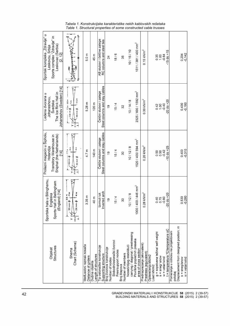
GRAĐEVINSKI MATERIJALI I KONSTRUKCIJE 58 (2015) 2 (39-57) BUILDING MATERIALS AND STRUCTURES 58 (2015) 2 (39-57)
42
Tabela 1. Konstrukcijske karakteristike nekih kablovskih rešetaka Table 1. Structural properties of some constructed cable trusses
GRAĐEVINSKI MATERIJALI I KONSTRUKCIJE 58 (2015) 2 (39-57) BUILDING MATERIALS AND STRUCTURES 58 (2015) 2 (39-57)
43
3.2 Dynamic relaxation metoda
Ova metoda razvijena je u isto vreme kada i forcedensity metoda. Koristi se za analizu kablovskihstruktura, kao i drugih tipova konstrukcija. Metoda sezasniva na diskretizaciji prostora i koncentrisanju masa učvorovima diskretizovane mreže. Ovakav sistem oscilujepod dejstvom opterećenja dok ne dođe do stanjamirovanja izazvanog prigušenjem koje se javlja usistemu. Primenjuju se dve vrste prigušenja: viskozno ikinetičko. U slučaju viskoznih prigušenja trebapretpostaviti koeficijent prigušenja prema postojećimsmernicama. Pogrešan odabir vrednosti ovogkoeficijenta dovodi do sporije konvergencije i produžavaproces nalaženja ravnotežne geometrije sistema. Uslučaju kinetičkog prigušenja primenjuje se iterativnipostupak koji u konačnom dovodi do toga da rezidualnesile teže nuli, odnosno da sistem dolazi u ravnotežnugeometriju.
3.3 Transient stiffness metoda
Ova metoda nastala je razvojem metoda koje imajupretpostavku malih pomeranja, odnosno uzimaju u obzirgeometrijski nelinearno ponašanje konstrukcija. Samametoda je nelinearna. Matematički, problem se formulišeu vidu sistema linearnih algebarskih jednačina, koji se uspešno rešava primenom Njutn-Rafsonove metode -iterativnim postupkom1. Postupak rešavanja sistemajednačina ponavlja se sve dok vektor, koji predstavlja deoneuravnoteženog opterećenja u svim čvorovima sistema,ne bude jednak nuli ili se ne svede na približno dovoljnomalu vrednost, koja bitno ne utiče na željenu tačnostrezultata.
Metoda primenjuje seriju koraka u kojima se izraču-navaju pomeranja, pri čemu se u svakom narednomkoraku menja matrica krutosti. Otuda i naziv metode kojiu bukvalnom prevodu znači metoda kratkotrajnih ilitrenutnih krutosti. Postupak promene matrice krutostinastavlja se dok rezidualne sile ne postanu bliske nuli. Upoređenju s dynamic relaxation metodom, transientstiffness metoda dolazi do ravnotežne geometrije putemmanjeg broja iteracija, ali je zato trajanje tih iteracijaduže.
Osnovni problem u proračunu ovim postupkom jestekako da se pretpostave ulazni podaci za „početni” tzv. referentni položaj (sile i geometrija), imajući u vidu da uštapovima konstrukcije deluju sile, iako na nju ne delujespoljašnje opterećenje. Za pretpostavljene sile igeometriju, sistem treba da je u ravnoteži.
1Svaki iterativni postupak podrazumeva aproksimaciju - pretpostavku početnih, ulaznih podataka
3.2 Dynamic Relaxation Method
This method was also made at the same time when the Force Density Method was made. It is used both for analyzing cable structures and for analysing other types of constructions. The method is based on the discretion of space as well as on the concentration of masses in the nodes of the discrete truss. A system like this oscillates under the influence of loading until it reaches the state of lull caused by the suppression that occurs in the system. Two kinds of suppression are applied: viscous and kinetic. In viscous suppressions it is necessary to presume the coefficient of suppression according to the already existing directions. Choosing wrong values of this coefficient results in a slower convergence and makes the process of finding the equilibrium of systems’ geometry much longer. Iterative procedure is used in kinetic suppression and it finally leads to the fact that the residual forces tend to equal zero, and the system reaches geometrical equilibrium.
3.3 Transient Stiffness Method
This method was being made together with the development of the methods which were based on the presumption of small displacements, i.e. the methods which take into account geometrically nonlinear behaviour of structures. The method itself is nonlinear. Mathematically speaking, the problem is defined as a system of linear algebraic equations which can easily be solved using Newton-Raphson’s method the iterative procedure. The procedure of solving the equations is repeated until the vector which represents a part of unbalanced loading in all system’s nodes equals zero or reaches the value which is so small that it cannot significantly influence the sought accuracy of results.
This method consists of a serious of steps through which transitions are calculated and in each further step the matrix of stiffness is changed. That is why it got its name similar to its literal translation meaning short term or temporary stiffness. The procedure of changing the matrix of stiffness is continued until the residual forces reach approximately zero. When compared to Dynamic Relaxation Method, Transient Stiffness Method obtains equilibrium geometry using a smaller number of iterations but the time of iterations is longer.
The basic problem while using this procedure is how to predict the input data for the ‘initial’, the so called referential position (forces and geometry) having in mind that there are forces which are present in construction rods although itself it is unaffected by any external loading. For the predicted forces and geometry the system should be in equilibrium position.

GRAĐEVINSKI MATERIJALI I KONSTRUKCIJE 58 (2015) 2 (39-57) BUILDING MATERIALS AND STRUCTURES 58 (2015) 2 (39-57)
44
3.4 Analitička metoda
Ova metoda upotrebljena je za proračun krovnihnosača na objektima u Johaneshovu [11], Shipholu [14] iBilinghemu [14]. Zasniva se na korišćenju uslova ravno-teže i promene dužina lančanica pri opterećenju, formirajuse sistemi nelinearnih diferencijalnih jednačina [4–6, 9]. Ovaj način je prilično komplikovan, ako se ne uveduuprošćenja u postavci problema (npr. kablovska rešetka seposmatra kao neprekidna glatka površ-membrana, optere-ćenje je vertikalno, ravnomerno raspodeljeno, lančanica jegipka i plitka, ima oblik parabole, oslonci su nepomerljivi,kablovi su idealno elastični). Uprošćenjima i aproksi-macijama eliminišu se male veličine višeg reda, pa selinearizuje sistem diferencijalnih jednačina i svodi na lakorešiv problem sa očekivanom greškom od 6% do 10%.
3.5 Kombinovana analitičko-numerička metoda
Osim primene analitičkih i numeričkih metoda, postojii mogućnost njihove kombinacije. I analitičke i numeričkemetode imaju svojih prednosti i mana. Numeričkemetode brže rešavaju problem od analitičkih metoda, tedolaze do ravnotežne geometrije sistema kablovskerešetke, ali zato zahtevaju pretpostavljanje ulaznihparametara. Pretpostavljanje ulaznih parametara veomaje važno jer utiče na brzinu proračuna. Jedan od ključnihulaznih parametara jeste intenzitet sile prednaprezanja ukablovima, jer od njega umnogome zavisi stabilnostsame rešetke. Postoje preporuke koje se tiču intenzitetasila prednaprezanja u kablovima koje bi trebalo da olakšaju pretpostavljanje ovog ulaznog parametra,međutim, postojeće preporuke nisu dovoljno preciznodefinisane. To za posledicu najčešće ima nedovoljnuzategnutost konstrukcije koja uzrokuje neispunjavanjepostojećih kriterijuma stabilnosti. Zato se postupak moraponavljati iz početka s većim pretpostavljenim intenzite-tom sila u kablovima. Ovo ponavljanje dovodi doneželjenog produžavanja ukupnog vremena proračuna, izato je bilo neophodno naći način da se ceo postupakoptimizuje.
Rešenje je pronađeno upravo u kombinacijinumeričkih metoda sa analitičkim. Na ovaj način, koristese prednosti obe vrste metoda, dok se njihovi nedostaciminimiziraju. Konkretno, analitička metoda koristi se zadobijanje ulaznih parametara za numeričku metodu.Time se izbegava pretpostavljanje parametara, jer onomože biti neprecizno i omogućava nestabilnost kon-strukcije koja je vidljiva tek na kraju proračuna. S drugestrane, nedostaci primene samo analitičke metodeogledaju se u dužem vremenu proračuna i grešci koja sejavlja u rezultatima usled aproksimacija i eliminacijemalih veličina višeg reda. Primena računara rešavaproblem dugog analitičkog proračuna, dok kombinacija snumeričkim metodom smanjuje greške u rezultatima.Kao najpodesnija metodologija za proračun kablovskih rešetaka izabrana je kombinacija analitičkog i numeri-čkog transient stiffness metoda [12,13]. Već je pomenutoda su pretpostavljanje geometrije i intenzitetaprednaprezanja najveći problem transient stiffnessmetode. Kombinacija sa analitičkim metodom rešava nesamo problem intenziteta prednaprezanja, već i
3.4 Analytical Method
This method was used for calculating roof girders on the buildings in Johaneshov [11], Shiphol [14], and Bilinghem [14]. It is based on using the equilibrium conditions and the change in catenary lengths while loading it. Systems of nonlinear differential equations are formed [4-6, 9].
This procedure is rather complicated if no simplifications are introduced in defining the problem, (for example a cable truss is regarded to be a continuous plane surface - a membrane, loading is vertical, equally distributed, the catenary is elastic and shallow in the shape of a parable, support points are immovable, cables are ideally elastic…) Simplifications and approximations eliminate small values of a higher rank and lead to a system of differential equations reducing it to a problem that can be solved; the expected error can be from 6% up to 10%.
3.5 Combined analytical-numerical method
Besides being used separately, analytical and numerical methods can be combined. Both analytical and numerical methods have their advantages and disadvantages. The use of numerical methods, if compared to the analytical ones, solve problems more quickly and reach the equilibrium geometry of the cable truss system, but at the same time they require the prediction of the input parameters. The process of predicting the input parameters is very important because it influences the speed of calculation. The intensity of the prestressing forces in cables is one of the most important input parameters, because the stability of a truss itself depends upon it. There are some recommendations concerning the intensity of prestressing forces in cables which could make predicting this input parameter easier, however the already existing recommendations are not defined enough precisely. It causes an inadequate level of construction’s stressing leading to the lack of fulfilment of the already existing stability criteria. Thus, the process must be repeated from the very beginning and the prediction of a larger intensity of the forces in cables must be made. This repetition makes the time necessary for completing the calculation much longer and it was necessary to elaborate a new method in order to make the process more adequate.
The situation was resolved by combining the numerical method with the analytical one. In this way it is possible to combine the advantages of both methods and to make their disadvantages less frequent. Precisely speaking, the analytical method is used for obtaining the input parameters necessary for the numerical method. In this way it is possible to avoid predicting parameters because it can be imprecise and lead to construction’s instability which is obvious only at the end of the calculation. On the other hand, the shortcomings of using the analytical method only are longer period of calculation time and elimination of small values of higher rank. The use of computers solves the problem of long analytical calculation, while its combination with numerical method lessens the mistakes in results. This combination of the analytical and numerical method was chosen as the most appropriate one for calculating cable

GRAĐEVINSKI MATERIJALI I KONSTRUKCIJE 58 (2015) 2 (39-57) BUILDING MATERIALS AND STRUCTURES 58 (2015) 2 (39-57)
45
geometriju sistema kablovske rešetke. Za dobijanjereferentnog položaja korišćen je modifikovan postupakprofesora Balgača [4, 5, 6]. Modifikacija ovog postupkaogledala se u tome što je on prilagođen primeni naračunaru i primeni na kablovske rešetke. Istovremeno,određeni elementi proračuna su uopšteni, te je na tajnačin omogućena njegova primena i na neke drugetipove konstrukcija. Ovako modifikovan postupakprofesora Balgača daje izuzetno tačne rezultate započetni položaj sistema i to pri veoma kratkom vremenuproračuna. Glavni uslov za stabilnost prema postupkuprofesora Balgača jeste postojanje sile kontakta „v”. Silakontakta je vertikalna komponenta sile kojomprednaprežući kabl opterećuje noseći. Postojanje sile kontakta prema Balgaču znači da ona mora da postoji i unajnepovoljnijem slučaju opterećenja. Drugim rečima,prednaprežući kabl uvek mora da opterećuje nosećikako bi kablovska rešetka bila stabilna.
Primena kombinovanog analitičko-numeričkog meto-da uslovljena je primenom računara odnosno origi-nalnog1 softvera „Cabl”, prema blok-šemi datoj na Slici2. Softver „Cabl” sadrži tri programske celine: „Cabl-T” (modul koji koristi analitičku metodu), „Cabl-TP” (modulkoji povezuje analitički dobijene rezultate s modulom kojiće ih koristiti kao početne u iterativnom postupku ponumeričkoj Transient Stiffness Method) i „Cabl-N” (numerički modul-Transient Stiffness Method).
4 KONTROLA RAVNOTEŽE KABLOVSKIH REŠETAKA U REFERENTNOM POLOŽAJU TRANSIENT STIFFNESS METODOM
Za gore definisane konstrukcije prethodno napreg-nutih kablovskih rešetaka obešenog krova, izvršena jeprovera ravnoteže u referentnom položaju (faza potpunog prethodnog naprezanja)[12,13,19]. Pritom, nasistem ne deluje spoljašnje opterećenje. Parametrireferentnog položaja: koordinate čvorova i sile uštapovima dobijeni su primenom programa CABL-T po metodi prof. Balgača, koja je prilagođena za kablovskerešetke i programski prilagođena za računarskuprimenu. Programom CABL-TP formirana je ulaznadatoteka za transient stiffness metod, tj. definisanakonfiguracija sistema: numeracija čvorova, povezivanještapova, opterećenje i temperaturna promena u štapovi-ma, a za preuzete podatke iz programa CABL-T.
Podaci dobijeni programom CABL-T predstavljajuravnotežno stanje konstrukcije u referentnom položaju, adobijeni su analitičkim postupkom prof. Balgača. Tran-sient stiffness metodom, tj. programom CABL-N, kon-trolisana je ravnoteža sistema, prema blok-šemi postup-ka proračuna [1] prikazanoj na Slici 2. Dobijeni rezultati
1 Autor softvera „Cabl” je prvopotpisani autor ovog rada
trusses [12, 13], We have already mentioned that the prediction of geometry and the intensity of prestressing is the biggest problem of the Transient Stiffness Method. The combination with the analytical method solves both the problem of the intensity of prestressing and geometry of a cable truss. Modified procedure of professor Balgacs [4, 5, 6] was used for obtaining the referential position. The modification of the procedure consisted in the fact that it was adapted to computer use and application on cable trusses. At the same time some of the calculation elements were generalized and in that way it was made possible to use it on some other construction types. This modified procedure of professor Balgacs gives very accurate results for the initial position of system after a very short time of calculation. The most important condition for stability, according to professor Balgacs’s procedure, is the presence of the contact force ‘v’. The contact force is a vertical component of force through which a prestressing cable loads the carrying one. According to professor Balgacs , the presence of the contact force means that it also must be present in the most unfavourable loading situation. In other words, the prestressing cable must always load the carrying one to ensure the stability of the cable truss.
The use of the combined analytical-numerical method is conditioned by the use of PC, actually the original software1 ”Cabl “according to the block-scheme given in Figure 2. The software ”Cabl” consists of three programme units:”Cabl-T” (the module uses the analytical method), “Cabl-TP” ( the module connects the results which were analytically obtained to the module which is going to use them as the initial ones in the iterative procedure while applying the numerical Transient Stiffness Method), and “Cabl –N” (numerical module-Transient Stiffness Method).
4 CONTROLLING THE EQUILIBRIUM OF CABLE TRUSSES IN THE REFERENTIAL POSITION USING TRANSIENT STIFFNESS METHOD
The control of the equilibrium in the referential position was done for the already mentioned structures since they consist of the prestressed cable trusses of hanged roofs (the phase of complete prestressing) [12, 13, 19]. In this case the system is uninfluenced by external loading .The parameters of the referential position: nodes coordination and forces in members are obtained using the programme “CABL-T” according to professor Balgac’s method which was adapted both for cable trusses and as a programme for computer use. The input data base for the Transient stiffness Method was obtained through the use of programme “CABL-TP”i.e. the configuration of the system was defined: nods numeration, connection of rods, loading and temperature changes in cable members for the data overtaken from programme “Cabl-T”.
The data obtained through CABL-T represent the equilibrium state of the construction in the referential position obtained using the analytical procedure of professor Balgac. Through the use of Transient Stiffness
1 Author of the software "Cable" is the first signed author of this paper

GRAĐEVINSKI MATERIJALI I KONSTRUKCIJE 58 (2015) 2 (39-57) BUILDING MATERIALS AND STRUCTURES 58 (2015) 2 (39-57)
46
Slika 2. Blok-šema algoritma analitičko-numeričkog proračuna prethodno napregnutih kablovskih struktura

GRAĐEVINSKI MATERIJALI I KONSTRUKCIJE 58 (2015) 2 (39-57) BUILDING MATERIALS AND STRUCTURES 58 (2015) 2 (39-57)
47
Figure 2. Block diagram of the algorithm of analytical and numerical calculation method for prestressed cable structures

GRAĐEVINSKI MATERIJALI I KONSTRUKCIJE 58 (2015) 2 (39-57) BUILDING MATERIALS AND STRUCTURES 58 (2015) 2 (39-57)
48
složeni su tabelarno. Zbog preglednosti rezultata, prikazane su samo maksimalne vrednosti pomeranja i sila u pojasnim štapovima:
− Maksimalna korekcija vertikalnih koordinata
slobodnih čvorova sistema (Tabela 2). Horizontalnapomeranja su zanemarljivo mala.
− Ukupne sile u štapovima i njihove korekcije(Tabela 3). U sistemu ne postoje nenapregnuti (labavi)stapovi u referentnom položaju.
Method, i.e. the programme CABL-N we controlled the equilibrium of the system according to the block-scheme of the calculation procedure [1] shown in picture 2. The obtained data are classified in tables. Only the maximum values of movements and the forces in cable members are shown because of an easy survey.
− Maximum correction of vertical coordinates of the system’s free nods (Table 2) Horizontal movements are insignificantly small
− All of the forces in members and their corrections (Table 3). The system does not include unstressed (loose) members in referential position.
Tabela 2. Maksimalna korekcija pomeranja slobodnih čvorova sistema u referentnom položaju – čvor u sredini raspona
Table 2. The maximum displacement correction of free nodes in the reference position - the node in the middle of span
Vertikalni položaj čvora dobijen programom
Vertical position of the node obtained
from program
Sportska hala u Bilinghemu,
Engleska Sports Hall in Bellingham (England)
Prolazni magacin u Šipholu, Holandija Transitory
Warehouse in Shiphal (the Netherlands)
Ledena dvorana u Johaneshovu,
Švedska The Ice Rink Hall in Johaneshov
(Sweden)
Sportski kompleks „Zdravlje” u
Leskovcu, Srbija Sports complex
“Zdravlje” in Leskovac (Serbia)
CABL-T 4,597 m 4,819 m 4,349 m 4,017 m CABL-N 4,586 m 4,805 m 4,334 m 3,999 m Korekcija Correction 1,13 cm 1,36 cm 1,46 cm 1,82 cm
Odstupanje Deviation 2,5 ‰ 2,8 ‰ 3,4 ‰ 4,48 ‰
Tabela 3. Maksimalna korekcija sila u pojasnim štapovima sistema u referentnom položaju Table 3. The maximum force corrections in cable members in reference position
Vertikalni položaj čvora dobijen programom
Force obtained from the program
Sportska hala u Bilinghemu,
Engleska Sports Hall in Bellingham (England)
Prolazni magacin u Šipholu,
Holandija Transitory
Warehouse in Shiphal (the Netherlands)
Ledena dvorana u Johaneshovu,
Švedska The Ice Rink Hall in Johaneshov
(Sweden)
Sportski kompleks „Zdravlje” u
Leskovcu, Srbija Sports complex
“Zdravlje” in Leskovac (Serbia)
CABL-T 402,770 kN 617,048 kN 929,168 kN 249,288 kN CABL-N 418,751 kN 637,592 kN 966,349 kN 265,722 kN Korekcija Correction 15,981 kN 20,544 kN 37,181 kN 16,434 kN
Gor
nji-n
oseć
i ka
bl
Car
ryin
g ca
ble
Odstupanje Deviation 3,82 % 3,22 % 3,85 % 6,18 %
CABL-T 298,992 kN 408,463 kN 908,391 kN 237,074 kN CABL-N 293,004 kN 400,515 kN 891,884 kN 239,076 kN Korekcija Correction -5,988 kN -7,948 kN -16,508 kN -3,002 kN
Don
ji-st
abiliz
ujuć
i ka
bl
Pres
tress
ing
cabl
e Odstupanje Deviation 2,05 % 1,98 % 1,85 % 1,26 %
4.1 Diskusija na osnovu rezultata
Očigledna je opravdanost primene predloženemetode za pribavljanje početnih parametara za konačanproračun prethodno napregnutih kablovskih struktura potransient stiffness metodi.
4.1 The discussion of the results
The necessity to use the already suggested method for obtaining the initial parameters for the final calculation of prestressed cable structures according to Transient Stiffness Method is obvious.
GRAĐEVINSKI MATERIJALI I KONSTRUKCIJE 58 (2015) 2 (39-57) BUILDING MATERIALS AND STRUCTURES 58 (2015) 2 (39-57)
49
Neznatne su korekcije geometrije tačaka sistema, atakođe i sila u štapovima. Maksimalne korekcijegeometrije su: 1.13 cm, 1.36 cm, 1.46 cm i 1.82 cm.Maksimalne korekcije sila u štapovima nosećeg kablajesu: 3,22% do 6,18% u odnosu na silu dobijenu transient stiffness metodom, dok su korekcije sila uštapovima stabilizujućeg kabla u granicama 1,26% do2,05%.
Pretpostavljeni podaci vrlo su bliski ravnotežnomstanju, jer se konačni ravnotežni položaj dobija kroz 3iteracije programom CABL-N.
5 PRORAČUN KABLOVSKIH REŠETAKA ZA PRORAČUNSKA OPTEREĆENJA TRANSIENT STIFFNESS METODOM
Tipični primeri kablovskih rešetaka za pokrivanjeraspona koji se kreću od 60 m do 80 m, s lakim krovnimpokrivačem, analizirani su u prethodnom odeljku izaspekta opravdanosti primene kombinovane, analitičko-numeričke metode, za dobijanje parametara ureferentnom položaju sistema. Proračun analiziranihkablovskih rešetaka za projektovana opterećenja daćenam odgovore konstrukcija, koji će biti analizirani izaspekta kriterijuma stabilnosti [12,13,19].
Svaka od analiziranih konstrukcija, prvobitno jeprethodno napregnuta - sračunati početni parametri poanalitičkoj metodi profesora Balgača, koja je prilagođenaza primenu na kablovske rešetke i primenu na računaru(programski modul CABL-T). Pretprocesor CABL-TP formirao je ulaznu datoteku za MKP. Programski modulCABL-N, sa opcijom provere ravnoteže za referentnipoložaj (faza potpunog prednaprezanja), proveromravnoteže formirao je i novu ulaznu datotekuINPUT.DAT s podacima o svim fazama opterećenja.Opterećenja deluju na uravnoteženu prethodnonapregnutu konstrukciju kablovskih rešetaka.
Opterećenja deluju na konstrukcije, kao što jepredviđeno tadašnjim projektima (Tabela 1), a samakonstrukcija prolazi kroz sledeće faze opterećenja, kojedeluju na prethodno zategnutu stabilnu konstrukciju:
(1) Sopstvena težina krova i konstrukcije g, (2) Sopstvena težina krova i konstrukcije i sneg: g+s (3) Sopstvena težina krova i konstrukcije, sneg i sisajuće
dejstvo vetra na celoj površini krova: g+s-w (4) Sopstvena težina krova i konstrukcije i sisajuće
dejstvo vetra na celoj površini krova: g-w (5) Sopstvena težina krova i konstrukcije i negativna
temperaturna promena na štapove sistema g-t, (6) Sopstvena težina krova i konstrukcije i pozitivna
temperaturna promena na štapove sistema g+t, (7) Sopstvena težina krova i konstrukcije, sneg i
negativna temperaturna promena na štapove sistema: g+s-t (8) Sopstvena težina krova i konstrukcije, sneg i
pozitivna temperaturna promena na štapove sistema: g+s+t (9) Sopstvena težina krova i konstrukcije, sneg, sisajuće
dejstvo vetra na celoj površini krova i negativna temperaturnapromena na štapove sistema: g+s-w-t
(10) Sopstvena težina krova i konstrukcije, sneg, sisajućedejstvo vetra na celoj površini krova i pozitivna temperaturnapromena na štapove sistema: g+s-w+t
(11) Sopstvena težina krova i konstrukcije, sisajućedejstvo vetra na celoj površini krova i negativna temperaturnapromena na štapove sistema: g-w-t
(12) Sopstvena težina krova i konstrukcije, sisajućedejstvo vetra na celoj površini krova i pozitivna temperaturna promena na štapove sistema: g-w+t
The corrections of the system’s geometry points, as well as of the forces in members are insignificant. Maximum corrections of the system’s geometry points are: 1.13cm, 1.46cm, and 1.82cm. Maximum corrections of the forces in the carrying cable members are: 3.22%, up to 6.18% if compared to the force obtained through the Transient Stiffness Method; whereas the corrections of the forces in the cable members of the stabilizing cable are 1.26% up to 2.05%.
The predicted data are very close to the equilibrium state since the final equilibrium state is obtained through three iterations using the programme “CABL-N”
5 CABLE TRUSSES CALCULATION FOR THE CALCULATION LOADINGS OF THE TRANSIENT STIFFNESS METHOD
Typical examples of cable trusses for covering spans from 60m to 80m long using light roof coverings have been analyzed in the previous chapter. The analysis dealt with the aspects of the appropriate use of applied combined, analytical-numerical method for obtaining the parameters in the referential position of the system. The calculations of the cable trusses for the projected loadings will show us possible construction responses and they are going to be analyzed concerning the aspects of stability criteria. [12, 13, 19].
Each of the analyzed constructions was prestressed first-the initial parameters were calculated according to the analytical method of professor Balgac which had previously been adapted for the use on cable trusses and the use by computers (programme module “CABL-T”). The preprocessor “CABL-TP” had made the input data file for Transient Stiffness Method. Programme module “CABL-N” with the option for checking the equilibrium in the referential position (the phase of complete prestressing), had made a new input data file INPUT.DAT after having checked the equilibrium and it included the data about all loading phases.
The loadings affect the construction as the present projects predicted (Table 1), and the construction itself goes through the following loading phases which affect the prestressed stable construction:
(1) The own weight of both the roof and the construction g(2) The own weight of both the roof and the construction
and snow load g+s (3) The own weight of both the roof and the construction,
snow and the sucking effect of the wind on the whole roof surface: g +s-w
(4) The own weight of both the roof and the construction and the sucking effect of the wind on the hole roof surface: g +w
(5) The own weight of both the roof and the construction and the negative temperature change on the system’s members g -t
(6) The own weight of both the roof and the construction and the positive temperature change on the system’s members g +t
(7) The own weight of both the roof and the construction, snow and the negative temperature change on the system’s members: g +s-t
(8) The own weight of both the roof and the construction, snow and the positive temperature change on the system’s members: g +s +t
(9) The own weight of both the roof and the construction, snow, sucking effect of the wind on the whole roof surface and the negative temperature change in the system’s members: g

GRAĐEVINSKI MATERIJALI I KONSTRUKCIJE 58 (2015) 2 (39-57) BUILDING MATERIALS AND STRUCTURES 58 (2015) 2 (39-57)
50
Karakteristični parametri koji utiču na stabilnostanaliziranih kablovskih rešetaka prikazani su u Tabeli 4,za sve karakteristične faze opterećenja.
+s –w-t (10) The own weight of both the roof and the construction,
snow, sucking effect of the wind on the whole roof surface and the positive temperature change in the system’s members: g +s –w + t
(11) The own weight of both the roof and the construction, sucking effect of the wind on the whole roof surface and negative temperature change in the system’s members: g- w- t
(12) The own weight of both the roof and the construction, sucking effect of the wind on the whole roof surface and positive temperature change in the system’s members: g –w + t
Specific parameters that affect the stability of the analyzed cable trusses are shown in Table 4, foe all specific loading phases
Tabela 4. Karakteristični parametri koji utiču na stabilnost analiziranih kablovskih rešetaka
Sportska hala u
Bilinghemu, Engleska
Prolazni magacin
u Šipholu, Holandija
Ledena dvorana
u Johaneshovu,
Švedska
Sportski kompleks
„Zdravlje” u Leskovcu,
Srbija Referentni položaj Prednaprezanje
Projektovani položaj Prednaprezanje i sopstvena težina krova s konstrukcijom (1) faza opterećenja g Nenapregnuti štapovi Neki dijag.1 Neki dijag.1 Neki dijag.1 Neki dijag.1 Maksimalna sila u nosećem kablu [kN] 512.328 860.247 1159.645 405.023 Maksimalna sila u stabilišućem kablu [kN] 276.156 338.104 852.455 210.725 Pomeranja u odnosu na referentni položaj [m]
0.1877 0.3442 0.1874 0.1320
(2) faza opterećenja g+s Nenapregnuti štapovi Neki dijag.1 Neki dijag.1 Neki dijag.1 Neki dijag.1 Maksimalna sila u nosećem kablu [kN] 737.163 1118.094 1743.888 888.726 Maksimalna sila u stabilišućem kablu [kN] 183.646 242.893 651.260 122.844 Pomeranja u odnosu na projektovani položaj [m]
0.3514 0.3493 0.4542 0.2792
(3) faza opterećenja g+s-w Nenapregnuti štapovi Neki dijag.1 Neki dijag.1 Neki dijag.1 Neki dijag.1 Maksimalna sila u nosećem kablu [kN] 557.329 901.561 1507.784 581.215 Maksimalna sila u stabilišućem kablu [kN] 255.994 321.174 751.785 179.239 Pomeranja u odnosu na projektovani položaj [m]
0.0713 0.0523 0.2692 0.1038
(4) faza opterećenja g-w Nenapregnuti štapovi ne ne ne Neki dijag.2 Maksimalna sila u nosećem kablu [kN] 402.156 661.550 967.364 194.286 Maksimalna sila u stabilišućem kablu [kN] 335.104 398.773 911.259 296.851 Pomeranja u odnosu na projektovani položaj [m]
-0.0886 -0.2949 -0.1784 -0.2663
(5) faza opterećenja g-t Nenapregnuti štapovi Neki dijag.1 Neki dijag.1 Neki dijag.1 Neki dijag.1 Maksimalna sila u nosećem kablu [kN] 540.863 880.818 1229.884 427.371 Maksimalna sila u stabilišućem kablu [kN] 297.095 353.324 949.431 230.347 Pomeranja u odnosu na projektovani položaj [m]
-0.0016 -0.0171 -0.0165 -0.0217
(6) faza opterećenja g+t Nenapregnuti štapovi Neki dijag.1 Neki dijag.1 Neki dijag.1 Neki dijag.1 Maksimalna sila u nosećem kablu [kN] 484.796 809.471 1090.078 382.892 Maksimalna sila u stabilišućem kablu [kN] 254.204 299.668 814.646 191.480 Pomeranja u odnosu na projektovani položaj [m]
0.018 -0.0255 0.017 0.0237

GRAĐEVINSKI MATERIJALI I KONSTRUKCIJE 58 (2015) 2 (39-57) BUILDING MATERIALS AND STRUCTURES 58 (2015) 2 (39-57)
51
(7) faza opterećenja g+s-t Nenapregnuti štapovi Neki dijag.1 Neki dijag.1 Neki dijag.1 Neki dijag.1 Maksimalna sila u nosećem kablu [kN] 762.125 1136.690 1804.279 907.484 Maksimalna sila u stabilišućem kablu [kN] 206.402 258.162 729.567 142.829 Pomeranja u odnosu na projektovani položaj [m]
0.3308 0.3304 0.4293 0.2611
(8) faza opterećenja g+s+t Nenapregnuti štapovi Neki dijag.1 Neki dijag.1 Neki dijag.1 Neki dijag.1 Maksimalna sila u nosećem kablu [kN] 712.537 1072.279 1684.366 870.296 Maksimalna sila u stabilišućem kablu [kN] 160.815 204.597 572.717 102.927 Pomeranja u odnosu na projektovani položaj [m]
0.3723 0.3791 0.4797 0.2973
(9) faza opterećenja g+s-w-t Nenapregnuti štapovi Neki dijag.1 Neki dijag.1 Neki dijag.1 Neki dijag.1 Maksimalna sila u nosećem kablu [kN] 584.537 921.784 1571.237 601.161 Maksimalna sila u stabilišućem kablu [kN] 279.125 336.372 829.982 199.658 Pomeranja u odnosu na projektovani položaj [m]
-0.0531 0.040 0.2467 0.0861
(10) faza opterećenja g+s-w+t Nenapregnuti štapovi Neki dijag.1 Neki dijag.1 Neki dijag.1 Neki dijag.1 Maksimalna sila u nosećem kablu [kN] 530.441 851.665 1445.192 561.676 Maksimalna sila u stabilišućem kablu [kN] 233.728 283.014 673.351 158.837 Pomeranja u odnosu na projektovani položaj [m]
-0.0899 0.0836 0.2922 0.1214
(11) faza opterećenja g-w-t Nenapregnuti štapovi Ne Ne Ne Neki dijag.2 Maksimalna sila u nosećem kablu [kN] 439.825 685.507 1053.807 232.741 Maksimalna sila u stabilišućem kablu [kN] 355.455 411.798 983.680 320.191 Pomeranja u odnosu na projektovani položaj [m]
-0.3637 -0.3029 -0.1896 -0.2860
(12) faza opterećenja g-w+t Nenapregnuti štapovi Ne Ne Ne Neki dijag.2 Maksimalna sila u nosećem kablu [kN] 365.980 602.013 885.619 156.937 Maksimalna sila u stabilišućem kablu [kN] 314.678 368.648 859.882 273.576 Pomeranja u odnosu na projektovani položaj [m]
-0.2777 -0.2736 -0.1663 -0.2451
1 Dijagonalni štap koji povezuje oslonac stabilizujućeg kabla i noseći kabl, i svi štapovi koji su „paralelni” s njim. 2 Dijagonalni štap koji povezuje oslonac nosećeg kabla sa stabilizujućim kablom, i svi štapovi uz niži oslonac, koji su „paralelni” s njim.
Table 4. Parameters important for the stability of analyzed cable trusses
Sports Hall in Bellingham (England)
Transitory Warehouse in Shiphal (the Netherlands)
The Ice Rink Hall in Johaneshov (Sweden)
Sports complex “Zdravlje” in Leskovac (Serbia)
Reference position Prestress
Designed position Prestress and self weight (1) load phase g Non-stressed members Some diag.1 Some diag.1 Some diag.1 Some diag.1 Maximum force in carrying cable [kN] 512.328 860.247 1159.645 405.023 Maximum force in prestressing cable [kN] 276.156 338.104 852.455 210.725 Displacement from the reference position [m] 0.1877 0.3442 0.1874 0.1320 (2) load phase g+s Non-stressed members Some diag.1 Some diag.1 Some diag.1 Some diag.1 Maximum force in carrying cable [kN] 737.163 1118.094 1743.888 888.726 Maximum force in prestressing cable [kN] 183.646 242.893 651.260 122.844 Displacement from the reference position [m] 0.3514 0.3493 0.4542 0.2792

GRAĐEVINSKI MATERIJALI I KONSTRUKCIJE 58 (2015) 2 (39-57) BUILDING MATERIALS AND STRUCTURES 58 (2015) 2 (39-57)
52
(3) load phase g+s-w Non-stressed members Some diag.1 Some diag.1 Some diag.1 Some diag.1 Maximum force in carrying cable [kN] 557.329 901.561 1507.784 581.215 Maximum force in prestressing cable [kN] 255.994 321.174 751.785 179.239 Displacement from the reference position [m] 0.0713 0.0523 0.2692 0.1038 (4) load phase g-w Non-stressed members no no no Some diag.2
Maximum force in carrying cable [kN] 402.156 661.550 967.364 194.286 Maximum force in prestressing cable [kN] 335.104 398.773 911.259 296.851 Displacement from the reference position [m] -0.0886 -0.2949 -0.1784 -0.2663 (5) load phase g-t Non-stressed members Some diag.1 Some diag.1 Some diag.1 Some diag.1 Maximum force in carrying cable [kN] 540.863 880.818 1229.884 427.371 Maximum force in prestressing cable [kN] 297.095 353.324 949.431 230.347 Displacement from the reference position [m] -0.0016 -0.0171 -0.0165 -0.0217 (6) load phase g+t Non-stressed members Some diag.1 Some diag.1 Some diag.1 Some diag.1 Maximum force in carrying cable [kN] 484.796 809.471 1090.078 382.892 Maximum force in prestressing cable [kN] 254.204 299.668 814.646 191.480 Displacement from the reference position [m] 0.018 -0.0255 0.017 0.0237 (7) load phase g+s-t Non-stressed members Some diag.1 Some diag.1 Some diag.1 Some diag.1 Maximum force in carrying cable [kN] 762.125 1136.690 1804.279 907.484 Maximum force in prestressing cable [kN] 206.402 258.162 729.567 142.829 Displacement from the reference position [m] 0.3308 0.3304 0.4293 0.2611 (8) load phase g+s+t Non-stressed members Some diag.1 Some diag.1 Some diag.1 Some diag.1 Maximum force in carrying cable [kN] 712.537 1072.279 1684.366 870.296 Maximum force in prestressing cable [kN] 160.815 204.597 572.717 102.927 Displacement from the reference position [m] 0.3723 0.3791 0.4797 0.2973 (9) load phase g+s-w-t Non-stressed members Some diag.1 Some diag.1 Some diag.1 Some diag.1 Maximum force in carrying cable [kN] 584.537 921.784 1571.237 601.161 Maximum force in prestressing cable [kN] 279.125 336.372 829.982 199.658 Displacement from the reference position [m] -0.0531 0.040 0.2467 0.0861 (10) load phase g+s-w+t Non-stressed members Some diag.1 Some diag.1 Some diag.1 Some diag.1 Maximum force in carrying cable [kN] 530.441 851.665 1445.192 561.676 Maximum force in prestressing cable [kN] 233.728 283.014 673.351 158.837 Displacement from the reference position [m] -0.0899 0.0836 0.2922 0.1214 (11) load phase g-w-t Non-stressed members no no no Some diag.2 Maximum force in carrying cable [kN] 439.825 685.507 1053.807 232.741 Maximum force in prestressing cable [kN] 355.455 411.798 983.680 320.191 Displacement from the reference position [m] -0.3637 -0.3029 -0.1896 -0.2860 (12) load phase g-w+t Non-stressed members no no no Some diag.2 Maximum force in carrying cable [kN] 365.980 602.013 885.619 156.937 Maximum force in prestressing cable [kN] 314.678 368.648 859.882 273.576 Displacement from the reference position [m] -0.2777 -0.2736 -0.1663 -0.2451 1 Diagonal member connecting the support of the prestressing cable and the carrying cable, and all members “parallel” to it 2 Diagonal member connecting the support of the carrying cable and the prestressing cable, and all members “parallel” to it

GRAĐEVINSKI MATERIJALI I KONSTRUKCIJE 58 (2015) 2 (39-57) BUILDING MATERIALS AND STRUCTURES 58 (2015) 2 (39-57)
53
5.1 Analiza rezultata
Proračun konstrukcija koje su prikazane, pokazujeda nisu ispunjeni svi uslovi stabilnosti koji se pominju uliteraturi i primenjuju u praksi.
− Sportska hala u Bilinghamu (Engleska)zadovoljava u pogledu maksimalnih zatežućih sila unosećem kablu, ali u minimalnoj meri ne zadovoljava upogledu sila u stabilišućem kablu (više za oko 1,5%),kao ni u pogledu pomeranja u odnosu na projektovanipoložaj konstrukcije (više za oko 7%). Takođe, pojasninoseći i stabilišući kablovi jesu zategnuti u svim fazamaopterećenja, a dijagonalni štapovi su zategnuti samo ufazi prednaprezanja, dok je u narednim fazama optere-ćenja svaki drugi štap nenapregnut.
− Prolazni magacin u Šipholu (Holandija)zadovoljava u pogledu maksimalnih zatežućih sila unosećem i stabilišućem kablu, ali je na granici zadovolje-nja u pogledu pomeranja u odnosu na projektovanipoložaj konstrukcije. Takođe, pojasni noseći i stabilišućikablovi su zategnuti u svim fazama opterećenja, adijagonalni štapovi su zategnuti samo u fazi prednapre-zanja, dok je u narednim fazama opterećenja svaki drugištap nenapregnut.
5.1 The analysis of the results
The calculations of the constructions which are presented here show us that they have not satisfied all stability conditions which were mentioned in literature and used in practice.
− Sports Hall in Billingham (England) Considering the maximum stressing forces in the carrying cable the construction is satisfactory, but it is minimally unsatisfactory concerning the forces in the stabilizing cable (1.5% greater), as well as concerning the movements in relation to the projected position of the construction which are 7% increased. Stripe cables: the carrying and stabilizing ones are stressed in all loading phases, the diagonal ones are stressed only in the prestressing phase, whereas in the following loading phases only each second one is prestressed.
− Transitory Warehouse in Shiphal (the Netherlands) Considering the maximum stressing forces in the carrying and stabilizing cable the construction is satisfactory, but it is hardly satisfactory considering the movements in comparison with the projected position of the construction. Stripe cables: the carrying and stabilizing ones are stressed in all loading phases, the diagonal ones are stressed only in the prestressing phase, whereas in the following loading phases only each second one is prestressed.
Tabela 5. Kriterijumi stabilnosti i sračunati parametri analiziranih kablovskih rešetaka
Sportska hala u
Bilinghemu, Engleska
Prolazni magacin
u Šipholu, Holandija
Ledena dvorana
u Johaneshovu, Švedska
Sportski kompleks
„Zdravlje” u Leskovcu, Srbija
Nenapregnuti štapovi Da – dijagon. Da – dijagon. Da – dijagon. Da - dijag.
Maksimalna sila u nosećem kablu kN 762.125 1136.690 1804.279 907.484 Faza opterećenja (7) g+s-t (7) g+s-t (7) g+s-t (7) g+s-t
1Maks. dozvoljena sila u nosećem kablu kN (maksimalna sila multiplikovana odgovarajućim parcijalnim koeficijentom)
1463 2100 3969 1996
2 Kataloška računska prekidna sila 1570 2390 3650 2277
Maksimalna sila u stabilišućem kablu kN 355.455 411.798 983.680 320.191 Faza opterećenja (11) g-w-t (11) g-w-t (11) g-w-t (11) g-w-t
(3) Maks. dozvoljena sila u stabilišućem kablu kN (maksimalna sila multiplikovana odgovarajućim parcijalnim koeficijentom)
711 824 2164 640
(4) Kataloška računska prekidna sila 700 933 2500 615
Maks.pomeranje u odnosu na projek. položaj m
-0.3637 -0.3791 -0.4797 0.2860
Faza opterećenja (11) g-w-t (8) g+s+t (8) g+s+t (11) g-w-t 3 Maks.dozv.pomer. u odnosu na projekt. polož. m
0.227 0.257 0.277 0.200
4 Maks.dozv.pomer. u odnosu na projekt. polož. m
0.340 0.385 0.415 0.300
Prema efektivnim kriterijumima projektnih jačina kablova. 2 Prema katalogu proizvođača kablova. 3 Prema našem pravilniku za noseće čelične konstrukcije – (L/300). 4 Prema EC-3 maksimalni ugib za čelične konstrukcije – (L/200).
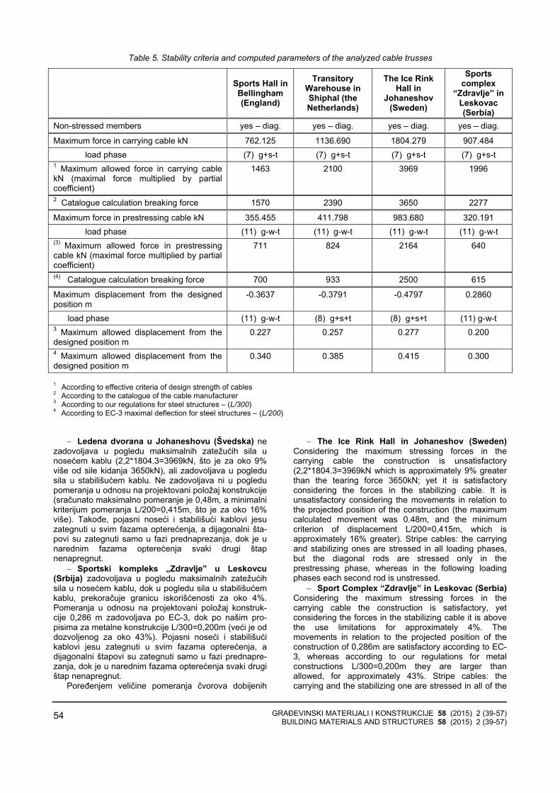
GRAĐEVINSKI MATERIJALI I KONSTRUKCIJE 58 (2015) 2 (39-57) BUILDING MATERIALS AND STRUCTURES 58 (2015) 2 (39-57)
54
Table 5. Stability criteria and computed parameters of the analyzed cable trusses
Sports Hall in Bellingham (England)
Transitory Warehouse in Shiphal (the Netherlands)
The Ice Rink Hall in
Johaneshov (Sweden)
Sports complex
“Zdravlje” in Leskovac (Serbia)
Non-stressed members yes – diag. yes – diag. yes – diag. yes – diag.
Maximum force in carrying cable kN 762.125 1136.690 1804.279 907.484 load phase (7) g+s-t (7) g+s-t (7) g+s-t (7) g+s-t
1 Maximum allowed force in carrying cable kN (maximal force multiplied by partial coefficient)
1463 2100 3969 1996
2 Catalogue calculation breaking force 1570 2390 3650 2277
Maximum force in prestressing cable kN 355.455 411.798 983.680 320.191 load phase (11) g-w-t (11) g-w-t (11) g-w-t (11) g-w-t
(3) Maximum allowed force in prestressing cable kN (maximal force multiplied by partial coefficient)
711 824 2164 640
(4) Catalogue calculation breaking force 700 933 2500 615
Maximum displacement from the designed position m
-0.3637 -0.3791 -0.4797 0.2860
load phase (11) g-w-t (8) g+s+t (8) g+s+t (11) g-w-t 3 Maximum allowed displacement from the designed position m
0.227 0.257 0.277 0.200
4 Maximum allowed displacement from the designed position m
0.340 0.385 0.415 0.300
1 According to effective criteria of design strength of cables 2 According to the catalogue of the cable manufacturer 3 According to our regulations for steel structures – (L/300) 4 According to EC-3 maximal deflection for steel structures – (L/200)
− Ledena dvorana u Johaneshovu (Švedska) ne zadovoljava u pogledu maksimalnih zatežućih sila unosećem kablu (2,2*1804.3=3969kN, što je za oko 9%više od sile kidanja 3650kN), ali zadovoljava u pogledusila u stabilišućem kablu. Ne zadovoljava ni u pogledupomeranja u odnosu na projektovani položaj konstrukcije(sračunato maksimalno pomeranje je 0,48m, a minimalnikriterijum pomeranja L/200=0,415m, što je za oko 16%više). Takođe, pojasni noseći i stabilišući kablovi jesuzategnuti u svim fazama opterećenja, a dijagonalni šta-povi su zategnuti samo u fazi prednaprezanja, dok je unarednim fazama opterećenja svaki drugi štapnenapregnut.
− Sportski kompleks „Zdravlje” u Leskovcu(Srbija) zadovoljava u pogledu maksimalnih zatežućihsila u nosećem kablu, dok u pogledu sila u stabilišućemkablu, prekoračuje granicu iskorišćenosti za oko 4%.Pomeranja u odnosu na projektovani položaj konstruk-cije 0,286 m zadovoljava po EC-3, dok po našim pro-pisima za metalne konstrukcije L/300=0,200m (veći je oddozvoljenog za oko 43%). Pojasni noseći i stabilišući kablovi jesu zategnuti u svim fazama opterećenja, adijagonalni štapovi su zategnuti samo u fazi prednapre-zanja, dok je u narednim fazama opterećenja svaki drugištap nenapregnut.
Poređenjem veličine pomeranja čvorova dobijenih
− The Ice Rink Hall in Johaneshov (Sweden) Considering the maximum stressing forces in thecarrying cable the construction is unsatisfactory (2,2*1804.3=3969kN which is approximately 9% greater than the tearing force 3650kN; yet it is satisfactory considering the forces in the stabilizing cable. It is unsatisfactory considering the movements in relation to the projected position of the construction (the maximum calculated movement was 0.48m, and the minimum criterion of displacement L/200=0,415m, which is approximately 16% greater). Stripe cables: the carrying and stabilizing ones are stressed in all loading phases, but the diagonal rods are stressed only in the prestressing phase, whereas in the following loading phases each second rod is unstressed.
− Sport Complex “Zdravlje” in Leskovac (Serbia) Considering the maximum stressing forces in the carrying cable the construction is satisfactory, yet considering the forces in the stabilizing cable it is above the use limitations for approximately 4%. The movements in relation to the projected position of the construction of 0,286m are satisfactory according to EC-3, whereas according to our regulations for metal constructions L/300=0,200m they are larger than allowed, for approximately 43%. Stripe cables: the carrying and the stabilizing one are stressed in all of the

GRAĐEVINSKI MATERIJALI I KONSTRUKCIJE 58 (2015) 2 (39-57) BUILDING MATERIALS AND STRUCTURES 58 (2015) 2 (39-57)
55
primenom kombinovane analitičko-numeričke metode(Tabela 5) sa originalnim dostupnim rezultatima (Tabela1), uočavaju se bitne razlike date u Tabeli 6.
loading phases, the diagonal rods are stressed only in the prestressing phase; whereas in the following loading phases each second rod is unstressed.
Comparing the results of movements values obtained using the combined analytical-numerical method (Table 5) with the original available results (Table 1) some very important differences were noticed. They are given in Table 6.
Tabela 6. Odstupanja sračunatih maksimalnih originalnih pomeranja i rezultata dobijenih programom „Cabl” analiziranih
kablovskih rešetaka, izraženo u m
Table 6. Deviation of calculated maximal original displacements from the results obtained by the program “Cabl” of the analyzed cable trusses, in m
Sportska hala u
Bilinghemu, Engleska
Sports Hall in
Bellingham (England)
Prolazni magacin
u Šipholu, Holandija Transitory
Warehouse in Shiphal (the Netherlands)
Ledena dvorana
u Johaneshovu, Švedska The Ice Rink Hall
in Johaneshov
(Sweden)
Sportski kompleks
„Zdravlje” u Leskovcu,
Srbija Sports complex
“Zdravlje” in Leskovac (Serbia)
(2) faza opterećenja / load phase g+s Originalni rezultat-analitički metod1
Original result-analytical method1 0,530 0,400 0,430 0,204
Analitičko-numerički metod (program „Cabl”) Analytical-numerical method (program “Cabl“)
0,351 0,349 0,454 0,279
Korekcija / Correction 0,179 0,051 0,024 0,075 Odstupanje / Deviation 50% 14,6% 5,3% 26,9% (2) faza opterećenja / load phase g-w Originalni rezultat-analitički metod1
Original result-analytical method1 -0,280 -0,310 -0,180 -0,142
Analitičko-numerički metod (program „Cabl”) Analytical-numerical method (program “Cabl“)
-0,089 -0,295 -0,178 -0,266
Korekcija / Correction 0,191 0,015 0,002 0,124 Odstupanje / Deviation 215% 5,1% 1,1% 46,6% Osim za Sportski kompleks „Zdravlje”, gde je primenjen Transient Stiffness Method 1 Except for the Sports complex “Zdravlje” where Transient Stiffness Method is applied
Velika odstupanja u odnosu na analitičku metodumoguća su zbog aproksimacija koje se uvode prilikomrešavanja analitičkih jednačina, kao i mogućih grešaka urasporedu štapova ispune (formiran model ne odgovarastvarnoj konfiguraciji štapova ispune nosača). Kodobjekata u Holandiji i Švedskoj odstupanja suzanemarljiva. Veća odstupanja kod objekata u Engleskoji Srbiji mogu da se pripišu neverodostojnom inelogičnom podatku iz literature (Tabela 1, [14, 10]).
Primena kombinovane analitičko-numeričke metodeukazala je na to da se brže i jednostavnije dolazi dorezultata proračuna kablovskih rešetaka primenomprograma „Cabl”. Ne pojavljuju se singularna matrica iprekid proračuna, jer su početni parametri koji se koristeu prvoj iteraciji Transient Stiffness Method dovoljno tačnida se proračun uvede u dalji iterativni postupak.Korišćenjem analitičkog metoda prof.Balgača, kontrolasile prethodnog naprezanja svedena je na ekvivalentdodatnog gravitacionog opterećenja, što umnogomepojednostavljuje analizu ovih nosača.
If compared with the analytical method, greater deviations are possible because of the approximations which were introduced while solving the analytical equations, as well as because of the possible errors in the distribution of filling rods (the model which was formed does not correspond to the real configuration of the girder’s nodes and members configuration). The deviations are insignificant in the structures in the Netherlands and Sweden. Greater deviations in the constructions in England and Serbia might be caused by the inauthentic and illogical data from literature (Table1, [14, 10]).
The use of the combined analytical-numerical method proved that it is much easier to obtain calculation results of cable trusses applying programme “Cabl”. There are no singular matrices and calculation interruptions since the initial parameters used in the first iteration of the Transient Stiffness Method are enough accurate so that the calculation can be proceeded into the following iterative procedure. Using the analytical method of professor Balgac, the control of the

GRAĐEVINSKI MATERIJALI I KONSTRUKCIJE 58 (2015) 2 (39-57) BUILDING MATERIALS AND STRUCTURES 58 (2015) 2 (39-57)
56
6 ZAVRŠNE NAPOMENE, ZAKLJUČCI I PREPORUKE
Analizom nekoliko karakterističnih konstrukcijakablovskih rešetaka, došlo se do određenih zaključaka:
− opravdana je upotreba analitičko-numeričkogmetoda za analizu ovog tipa konstrukcija (korekcije sila ipomeranja analitički dobijenih parametara vrlo su male[1, 12, 13]).
− Transient stifness metodom preračunate su sile ipomeranja za dvanaest slučajeva statičkog opterećenja iizvedeno je poređenje s važećim kriterijumima stabil-nosti. Utvrđeno je da se u skoro sva četiri analiziranaslučaja konstrukcija javljaju u manjoj ili većoj meriprekoračenja maksimalne sile u nosećem ili stabilišućemkablu, nenapregnuti štapovi dijagonala u nekim odslučajeva opterećenja, kao i pomeranja veća oddozvoljenih.
− Nenapregnutost štapova ispune u pojedinim fazamaopterećenja dovodi do veće horizontalne pomerljivosti imogućeg vitoperenja nosača u vertikalnoj ravni. Vitope-renje nosača može da dovede do veće horizontalnepomerljivosti i stvaranje uslova za rezonantne efekte.Krovni nosači uglavnom ispunjavaju kriterijume statičkestabilnosti, ali se iz aspekta postizanja dinamičke stabil-nosti postavlja pitanje dovoljne sile prednaprezanja kako bise zadovoljili kriterijumi 2.e [3, 11-14].
S obzirom na duži period eksploatacije ovih objekatai osavremenjene kriterijume stabilnosti, a imajući u viduprezentirane rezultate, nameće se potreba procenestabilnosti i bezbednosti korišćenja ovih objekata.Preporuke autora ovog rada jesu:
− Makroskopski detaljni pregled kablovskih strukturau pogledu mehaničkih i hemijskih oštećenja nosećih ispojnih elemenata;
− Precizno utvrđivanje trenutne geometrije nosačapod stalnim opterećenjem geodetskim metodama;
− Realni statički i dinamički uticaji (opterećenja) koji deluju na krovnu površinu;
− Ispitivanjem utvrditi deformacije usled probnogopterećenja i svojstvene vibracije kablovskih nosača;
− Sprovesti ponovnu statičku analizu za utvrđenerealne uticaje na osnovu geodetskog snimkakonfiguracije nosača i karakteristika kablova;
− Izvršiti dinamičku analizu uticaja vetra za lokalneuslove i mogućnost pojave rezonance [1];
− Izvesti konačan zaključak u pogledu ispunjenjakriterijuma stabilnosti a-e iz odeljka 2 ovog rada.
prestressing forces is reduced to the equivalent of the additional gravity loading, which makes the analysis of the girders much more simple.
6 FINAL REMARKS, CONCLUSIONS AND RECOMMENDATIONS
Having analyzed several characteristic constructions consisting of cable trusses some specific conclusions were made:
− The use of analytical-numerical method for analyzing this type of constructions is justified. (Movements and forces corrections of analytically obtained parameters are very small) [1, 12, 13]
− Using the Transient Stiffness Method the forces and displacements in 12 cases of static loadings were calculated and compared to the already updated stability criteria. It was determined that in all of the four analyzed structures there were some exceed of the maximum forces either in the carrying or in the stabilizing cable, that there were some unstressed diagonal rods in some loading cases, and that there were some movements greater than the allowed ones.
− The unstressed filling rods in some loading cases cause greater horizontal movability and possible bending of a girder in the vertical plane. The bending of a girder can cause a larger horizontal movability and make conditions for resonance effects. Roof girders satisfy the criteria in most of the cases. However, concerning the aspects of reaching dynamic stability there is a problem of the sufficient prestressing force so that the criteria could be fulfilled.
Bearing in mind that the buildings have been used for quite long period of time, that stability criteria were updated and all the results were presented in the paper, it is necessary to estimate their stability properly as well as their safe use. The authors’ recommendations are:
− Macroscopic detailed examination of cable structures concerning mechanic and chemical damages in the carrying and connecting elements,
− Precise estimation of girders’ geometry under constant loading using geodetic methods
− Estimating real static and dynamic influences (loadings) which affect the roof surface,
− Measuring deformations caused by experimental loading and own vibrations of cable girders,
− Making repeated static analysis for estimation of real influences based on the geodetic estimation of girders’ and characteristic cables’ configuration,
− Making dynamic analysis of the influence of wind gusts for the local position and possible occurrence of resonance [1],
− Drawing final conclusion on the fulfillment of updated stability criteria (a-e from Chapter 2 of the Paper).

GRAĐEVINSKI MATERIJALI I KONSTRUKCIJE 58 (2015) 2 (39-57) BUILDING MATERIALS AND STRUCTURES 58 (2015) 2 (39-57)
57
7 LITERATURA REFERENCES
[1] Aćić M., Vlajić Lj., Kostić D.: Determination ofprestressing levels for cable trusses as function oftheir stability, Građevinar, Vol. 12, 2013.
[2] Aćić M., Vlajić Lj., Kostić D.: Eksperimentalna analizadvopojasne lančanice konstrukcije visećeg krovaSRC „Zdravlje” u Leskovcu, VII Simpozijum DGKMOhrid, 1997., ST3 str.1–6.
[3] AISI Manual for Structural Applications of SteelCables for Buildings, 1996.
[4] Balgač Edmund: Obešeni krov velike izložbenehale leskovačkog sajma tekstila, Betonske predna-pregnute konstrukcije, Izgradnja (spec.izd.), 1969.
[5] Balgač Edmund: Određivanje sila u kablovimaprethodno napregnute mreže obešenih krovovaoblika hiperboličkog paraboloida, Izgradnja, 1969.(11, 12)
[6] Balgač Edmund: Die neue Ausstellungshalle derTextilmesse in Leskovac, Beton undStahlbetonbau, 1961.(7)
[7] Balgač Edmund: Obešeni krov doma omladine isportova u Zemunu, Izgradnja, 1971.(7)
[8] Balgač Edmund: Hala za sport i rekreaciju uSubotici, Izgradnja, 1988.(4)
[9] Gopčević Š., Brčić S., Žugić Lj.: Dinamička analizakablova, Građevinski materijali i konstrukcije, godina LV – 2012, Vol. 55., str. 3–31.
[10] Ivković M., Radojičić T., Praščević ž., Radojičić V.: Dvopojasna prethodno napregnuta lančanica plivačkog bazena „Zdravlje” Leskovac, Savetovanje: „Modeliranje, proračun i ispitivanje konstrukcija”, Niš, 1993.
[11] Jawerth D., Schulz H.: Ein Beitrag zur Eigenschwingungen, windanfachenden Krafte und aerodinamischen Stabilitat bei hangenden Dachern, Der Stalbau, Berlin, Januar 1966.
[12] Kostić Dragan: Prilog rešenju problema stabilnosti dvopojasnih lančaničnih sistema, doktorska disertacija, GAF Niš, 2007.
[13] Kostić D.: Stabilni dvopojasni lančanični sistemi, Zadužbina Andrejević, Beograd, 93 str., 2013.
[14] Krishna Prem: Cable-Suspended Roofs, McGraw Hill Book Company, 1978.
[15] Lewis W.J.: Tension Structures, Form and behaviour, Thomas Telford, Reston, 201 str., 2003.
[16] Mladžov Rumen: Viseći konstrukcii, Tehnika, Sofija, 1987.
[17] Moskalev N. S.: Konstrukcii visjačih pokritia, Stroizdat, Moskva, 1980.
[18] Sobotka Zdenek: Zavešené strechy, Státní Nakladatelství Technické Literatury, Praha, 1962.
[19] Milošević V. Dependence of membrane deflection on the position and intensity of point loads. Structural Engineering International, Vol. 2015, No. 1, 2015, pp. 20–25
REZIME
ANALIZA STABILNOSTI NEKIH IZVEDENIH KABLOVSKIH REŠETAKA
Dragan KOSTIĆ Vuk MILOŠEVIĆ
U ovom radu prikazani su i analizirani primeriizgrađenih kablovskih rešetaka za pokrivanje velikihraspona, prema odabranim dostupnim podacima izliterature. Globalni odgovor konstrukcije na statičkaopterećenja, korišćenjem originalnog softvera kombi-novanom analitičko-numeričkom metodom, pružamogućnost dublje analize odabranih sistema. Takodobijeni rezultati analizirani su iz aspekta kriterijumastabilnosti, u odnosu na statička opterećenja (minimalnesile prednaprezanja, pojava nenapregnutih štapova, maksimalna pomeranja). Poređenjem dobijenih poda-taka s važećim kriterijumima stabilnosti, komentariše se trenutno stanje i formuliše se predlog za poboljšanjestabilnosti analiziranih kablovskih rešetaka.
Ključne reči: stabilnost, kablovske rešetke, transient stiffness metoda, force density metoda, dozvoljenapomeranja
SUMMАRY
ANALIZA STABILNOSTI NEKIH IZVEDENIH KABLOVSKIH REŠETAKA
Dragan KOSTIC Vuk MILOSEVIC
This paper is both a presentation and an analysis of some built cable trusses used for covering large spans according to some data which were selected and available from the literature. An overall response of a construction to static loadings applying the original software of the combined analytical-numerical method gives the possibility of a more comprehensive analysis of the chosen systems. The results obtained in this way were analyzed concerning stability criteria in relation to static loadings (minimum forces of prestressing, the occurrence of unstressed rods, exceeded displacement). Having compared the obtained data with the updated stability criteria we comment the present situation and suggest the ways of improving the stability of the cable trusses which were analyzed.
Key words: stability, cable trusses, transient stiffness method, force density method, allowed displacements

GRAĐEVINSKI MATERIJALI I KONSTRUKCIJE 58 (2015) 2 (39-57) BUILDING MATERIALS AND STRUCTURES 58 (2015) 2 (39-57)
58

GRAĐEVINSKI MATERIJALI I KONSTRUKCIJE 58 (2015) 2 (59-60) BUILDING MATERIALS AND STRUCTURES 58 (2015) 2 (59-60)
59
IN MEMORIAM
dr LJUBOMIR VLAJIĆ, dipl.inž.građ. redovni profesor
1941-2015
Iznenada, 30. aprila 2015. godine u Beogradu, zauvek nas je napustio profesor dr Ljubomir M. Vlajić, diplomirani inženjer građevinarstva. Rođen je 15. oktobra 1941. godine u Beogradu. Diplomirao je na Konstruktivnom smeru Građevinskog fakulteta (GF) Univerziteta u Beogradu, jula 1966. godine, iz predmeta „Ispitivanje konstrukcija”. Ovo opredeljenje bilo je vodilja u
njegovom celokupnom profesionalnom radu. Ljubomir Vlajić bio je nezaobilazan rukovodilac ispitivanja mnoštva građevinskih objekata, a poslednjih godina bio je angažovan kao konsultant pri ispitivanju značajnih objekata.
Nakon diplomiranja (1966) izabran je u zvanje asistenta na predmetu „Ispitivanje konstrukcija” na GF Univerziteta u Beogradu, gde je radio do 1970. godine. Posle toga radi u građevinskom preduzeću „Jedinstvo” iz Smederevske Palanke, kao glavni inženjer, a zatim i kao upravnik gradnje. U Institutu „Kirilo Savić” iz Beograda, od 1972. do 1982. godine, rukovodio je Odsekom za ispitivanje konstrukcija.
Na Građevinskom fakultetu u Subotici radi od septembra 1982. godine do septembra 2007. godine. Počeo je u zvanju predavača da bi napredovao do redovnog profesora. Značajno je pomenuti da od 1991. godine, paralelno s radom na fakultetu, aktivno radi kao naučni savetnik iz oblasti ispitivanja konstrukcija u Institutu „Kirilo Savić”. Doktorsku disertaciju „Ponašanje spojeva sa visokovrednim zavrtnjima pri eksploatacionom i graničnom opterećenju” odbranio je na Građevinskom fakultetu u Nišu, jula 1993. godine. Iste godine izabran je u zvanje vanrednog profesora, a u zvanje redovnog profesora izabran je 1999. godine na
GF Subotica, za grupu predmeta „Eksperimentalna analiza konstrukcija” i „Statika linijskih nosača 1”. Od septembra 2007. do 2015. godine radio je kao naučni savetnik u Saobraćajnom institutu CIP iz Beograda.
Pored ispitivanja konstrukcija, naučni i stručni rad profesora Vlajića obuhvatao je veoma široku problematiku građevinskog konstrukterstva, gde između ostalog spadaju: projektovanje, primena i kontrola visokovrednih zavrtnjeva, dijagnostika stanja, sanacije konstrukcija nakon teških oštećenja nastalih ekstremnom upotrebom objekata, kao i nakon ratnih razaranja. Bio je član komisije za mostove Ministarstva za infrastrukturu i energetiku Republike Srbije. U svojim radovima profesor Vlajić se zalagao da se rešavanje konstruktivnih problema na objektima zasniva na jedinstvu teorijske i eksperimentalne analize. Njegovi radovi propraćeni su ne samo savremenim metodama ispitivanja, već i savremenim metodama proračuna konstrukcija.
Tokom celog svog radnog veka uspešno je povezivao stručni i naučnoistraživački rad, čime je dao svoj puni doprinos i struci i nauci. Posebnu pažnju posvećivao je radu na obrazovanju i napretku svojih mlađih saradnika i studenata, kao i kolega iz struke, što ukazuje na to da je pored stručno-naučnih kvalifikacija posedovao i poseban afinitet za pedagoški rad sa studentima, kao i rad na stručnom usavršavanju mlađih saradnika. Zapažena su njegova izlaganja na stručno-naučnim skupovima na kojima je često nastupao s pozivnim referatima. Pri tome je izlagao svoja bogata iskustva, a odlikovali su ga i kritički duh i objektivnost.
Kao priznanje za njegov značajan doprinos široj oblasti građevinskog konstrukterstva, 2008. godine izabran je za redovnog člana Jugoslovenske inženjerske akademije (sada Inženjerske akademije Srbije). Profesor Vlajić bio je aktivan u više stručnih i naučnih udruženja s brojnim referatima koje su organizovali Savez građevinskih inženjera Srbije, Društvo za istraživanje materijala i konstrukcija (DIMK), i Društvo građevinskih

GRAĐEVINSKI MATERIJALI I KONSTRUKCIJE 58 (2015) 2 (59-60) BUILDING MATERIALS AND STRUCTURES 58 (2015) 2 (59-60)
60
konstruktera Srbije i ranije Jugoslavije. Učestvovao je, ne samo u radu, već i u organizovanju više naučno-stručnih skupova, a smrt ga je zadesila u vreme kada je bio član Programskog odbora Konferencije: Ocena stanja, održavanje i sanacije građevinskih objekata, a za Konferenciju: Savremena građevinska praksa, pripremio je i publikovano mu je saopštenje po pozivu, koje usled bolesti nije održao. To svedoči o njegovom neprestanom davanju doprinosa struci koju je istinski voleo.
Od najprepoznatljivijih stručnih rezultata profesora Vlajića ističu se statička i dinamička ispitivanja preko 400 različitih objekata kao što su: više mostova u Iraku, sportska hala „Beogradska Arena”, svi mostovi na pruzi Beograd–Bar, praktično svi mostovi preko reke Save i Dunava u Srbiji koji su izgrađeni od 1974. godine, uključujući novi most kod Beške i most Zemun–Borča, dok je za novi most preko Ade u Beogradu bio angažovan kao konsultant. Aktivno je radio na tehničkoj kontroli projekata.
Profesor Vlajić je bio i odgovorni projektant više desetina izvedenih kompleksnih objekata. Posle NATO bombardovanja 1999. godine, kao predsednik komisije za mostove, rukovodio je pripremom sanacija i obnovom 58 drumskih i železničkih mostova. Jedan od najznačajnijih projekata profesora Vlajića jeste glavni projektant sanacije i rekonstrukcije Palate „Ušće” na Novom Beogradu. Uspeh rekonstrukcije ovog objekta, između ostalog, ogleda se u ozbiljnosti i obimu oštećenja za koja su mnogi stručnjaci smatrali da su nepopravljiva i da objekat treba ukloniti. Društvo građevinskih konstruktera Srbije mu je za ovaj objekat dodelilo priznanje za najbolje ostvarenje u građevinskom konstrukterstvu za 2004. i 2005. godinu i nagradilo profesora Vlajića i članove tima s kojim je izveo pomenuti poduhvat. Na kongresu 2012. godine u
Vrnjačkoj Banji, Društvo građevinskih konstruktera Srbije profesoru Vlajiću dodelilo je Povelju za životno delo u oblasti građevinskog konstrukterstva.
Tokom rada na Građevinskom fakultetu Subotica intenzivno se bavio unapređivanjem predmeta „Eksperimentalna analiza konstrukcija” i „Dijagnostika stanja, održavanje, sanacija i revitalizacija konstrukcija” na diplomskim i poslediplomskim studijama. Učestvovao je u realizaciji eksperimenata u okviru magistarskih radova i dokotorskih disertacija svojih kolega. Kao mentor rukovodio je izradom magistarskog rada i doktorske disertacije Ilije Miličića i doktorske disertacije Danijela Kukarasa.
Od publikacija posebno se ističe knjiga monografskog karaktera „Visokovredni zavrtnji u Građevinskom konstrukterstvu” (2012), koja predstavlja jedinstveni doprinos problematici standardne i nestandardne primene. Ovo delo je plod višedecenijskog iskustva autora u primeni, podržano eksperimentalnim analizama. U njoj su visokovredni zavrtnji tretirani ne samo kao spojno sredstvo, već i kao konstrukcijski element. Koautor je knjige „Mostovi”, koja je trajni podsetnik na razaranja infrastrukturnih objekata, koja su nas zadesila 1999. godine. Profesor Vlajić se pored toga što je bio cenjen univerzitetski nastavnik, ubrajao u izuzetno darovite građevinske konstruktere širokog stručnog obrazovanja i interesovanja, a njegovi doprinosi u oblasti eksperimentalnog ispitivanja i istraživanja svrstavaju ga u naše vodeće stručnjake. Pominjemo i to da je često isticao kako je u svom radu imao značajnu podršku i razumevanje supruge Biljane, ćerke Milene i sina Milorada.
Juna 2015. godine
Radomir Folić Danijel Kukaras

GRAĐEVINSKI MATERIJALI I KONSTRUKCIJE 58 (2015) 2 (61-61) BUILDING MATERIALS AND STRUCTURES 58 (2015) 2 (61-61)
61
UPUTSTVO AUTORIMA*
Prihvatanje radova i vrste priloga U časopisu Materijli i konstrukcije štampaće se neobja-
vljeni radovi ili članci i konferencijska saopštenja sa odre-đenim dopunama ili bez dopuna. prema odluci Redakcionog odbora. a samo izuzetno uz dozvolu prethodnog izdavača prihvatiće se i objavljeni rad. Vrste priloga autora i saradnika koji će se štampati su: originalni naučni radovi. prethodna saopštenja. pregledni radovi. stručni radovi. konferencijska saopštenja (radovi sa naučno-stručnih skupova). kao i ostali prilozi kao što su: prikazi objekata i iskustava - primeri. diskusije povodom objavljenih radova i pisma uredništvu. prikazi knjiga i zbornika radova. kao i obaveštenja o naučno-stručnim skupovima.
Originalni naučni rad je primarni izvor naučnih informa-cija i novih ideja i saznanja kao rezultat izvornih istraživanja uz primenu adekvatnih naučnih metoda. Dobijeni rezultati se izlažu kratko. jasno i objektivno. ali tako da poznavalac problema može proceniti rezultate eksperimentalnih ili teorijsko numeričkih analiza i tok razmišljanja. tako da se istraživanje može ponoviti i pri tome dobiti iste ili rezultate u okvirima dopuštenih odstupanja. kako se to u radu navodi.
Prethodno saopštenje sadrži prva kratka obaveštenja o rezultatima istraživanja ali bez podrobnih objašnjenja. tj. kraće je od originalnog naučnog rada. U ovu kategoriju spadaju i diskusije o objavljenim radovima ako one sadrže naučne doprinose.
Pregledni rad je naučni rad koji prikazuje stanje nauke u određenoj oblasti kao plod analize. kritike i komentara i zaključaka publikovanih radova o kojima se daju svi neop-hodni podaci pregledno i kritički uključujući i sopstvene radove. Navode se sve bibliografske jedinice korišćene u obradi tematike. kao i radovi koji mogu doprineti rezultatima daljih istraživanja. Ukoliko su bibliografski podaci metodski sistematizovani. ali ne i analizirani i raspravljeni. takvi pregledni radovi se klasifikuju kao stručni pregledni radovi.
Stručni rad predstavlja koristan prilog u kome se iznose poznate spoznaje koje doprinose širenju znanja i prila-gođavanja rezultata izvornih istraživanja potrebama teorije i prakse. On sadrži i rezultate razvojnih istraživanja.
Konferencijsko saopštenje ili rad sopšten na naučno-stručnom skupu koji mogu biti objavljeni u izvornom obliku ili ih autor. u dogovoru sa redakcijom. bitno preradi i proširi. To mogu biti naučni radovi. naročito ako su sopštenja po pozivu Organizatora skupa ili sadrže originalne rezultate prvi put objavljene. pa ih je korisno uz određene dopune učiniti dostupnim široj stručnoj javnosti. Štampaće se i stručni radovi za koje Redakcioni odbor oceni da su od šireg interesa.
Ostali prilozi su prikazi objekata. tj. njihove konstrukcije i iskustava-primeri u građenju i primeni različitih materijala. diskusije povodom objavljenih radova i pisma uredništvu. prikazi knjiga i zbornika radova. kao i obaveštenja o naučno-stručnim skupovima.
Autori uz rukopis predlažu kategorizaciju članka. Svi radovi pre objavljivanja se recenziraju. a o prihvatanju za publikovanje o njihovoj kategoriji konačnu odluku donosi Redakcioni odbor.
Da bi se ubrzao postupak prihvatanja radova za publikovanje. potrebno je da autori uvažavaju Uputstva za pripremu radova koja su navedena u daljem tekstu.
Uputstva za pripremu rukopisa
Rukopis otkucati jednostrano na listovima A-4 sa marginama od 31 mm (gore i dole) a 20 mm (levo i desno). u Wordu fontom Arial sa 12 pt. Potrebno je uz jednu kopiju svih delova rada i priloga. dostaviti i elektronsku verziju na navedene E-mail adrese. ili na CD-u. Autor je obavezan da čuva jednu kopiju rukopisa kod sebe zbog eventualnog oštećenja ili gubitka rukopisa.
Od broja 1/2010. prema odluci Upravnog odbora Društva i Redakcionog odbora. radovi sa pozitivnim recenzijama i prihvaćeni za štampu. publikovaće se na srpskom i engleskom jeziku.
* Uputstvo autorima je modifikovano i treba ga u pripremi
radova slediti.
Svaka stranica treba da bude numerisana. a optimalni obim članka na jednom jeziku. je oko 16 stranica (30000 slovnih mesta) uključujući slike. fotografije. tabele i popis literature. Za radove većeg obima potrebna je saglasnost Redakcionog odbora.
Naslov rada treba sa što manje reči (poželjno osam. a najviše do jedanaeset) da opiše sadržaj članka. U naslovu ne koristiti skraćenice ni formule. U radu se iza naslova daju ime i prezime autora. a titule i zvanja. kao iime institucije u podnožnoj napomeni. Autor za kontakt daje telefone. faks i adresu elektronske pošte. a za ostale autore poštansku adresu.
Uz sažetak (rezime) od oko 150 do 200 reči. na srpskom i engleskom jeziku daju se ključne reči (do deset). To je jezgrovit prikaz celog članka i čitaocima omogućuje uvid u njegove bitne elemente.
Rukopis se deli na poglavlja i potpoglovlja uz numera-ciju. po hijerarhiji. arapskim brojevima. Svaki rad ima uvod. sadržinu rada sa rezultatima. analizom i zaključcima. Na kraju rada se daje popis literature.
Kod svih dimenzionalnih veličina obavezna je primena međunarodnih SI mernih jedinica.
Formule i jednačine treba pisati pažljivo vodeći računa o indeksima i eksponentima. Autori uz izraze u tekstu definšu simbole redom kako se pojavljuju. ali se može dati i posebna lista simbola u prilogu.
Prilozi (tabele. grafikoni. sheme i fotografije) rade se u crno-beloj tehnici. u formatu koji obezbeđuje da pri smanjenju na razmere za štampu. po širini jedan do dva stupca (8cm ili 16.5cm). a po visini najviše 24.5cm. ostanu jasni i čitljivi. tj. da veličine slova i brojeva budu najmanje 1.5mm. Originalni crteži treba da budu kvalitetni i u potpunosti pripremljeni za presnimavanje. Mogu biti i dobre. oštre i kontrastne fotokopije. Koristiti fotogrfije. u crno-beloj tehnici. na kvalitetnoj hartiji sa oštrim konturama. koje omogućuju jasnu reprodukciju. Skraćenice u prilozima koristiti samo izuzetno uz obaveznu legendu. Prilozi se posebno označavaju arapskim brojevima. prema redosledu navođenja u tekstu. Objašnjenje tabela daje se u tekstu.
Potrebno je dati spisak svih skraćenica korišćenih u tekstu.
U popisu literature na kraju rada daju se samo oni radovi koji se pominju u tekstu. Citirane radove treba prikazati po azbučnom redu prezimena prvog autora. Literaturu u tekstu označiti arapskim brojevima u uglastim zagradama. kako se navodi i u Popisu citirane literature. napr [1]. Svaki citat u tekstu mora se naći u Popisu citirane literature i obrnuto svaki podatak iz Popisa se mora navesti u tekstu.
U Popisu literature se navode prezime i inicijali imena autora. zatim potpuni naslov citiranog članka. iza toga sledi ime časopisa. godina izdavanja i početna i završna stranica (od - do). Za knjige iza naslova upisuje se ime urednika (ako ih ima). broj izdanja. prva i poslednja stranicapoglavlja ili dela knjige. ime izdavača i mesto objavljivanja. ako je navedeno više gradova navodi se samo prvi po redu. Kada autor citirane podatke ne uzima iz izvornog rada. već ih je pronašao u drugom delu. uz citat se dodaje «citirano prema...». Neobjavljeni članci mogu se pominjati u tekstu kao «usmeno saopštenje»
Autori su odgovorni za izneseni sadržaj i moraju sami obezbediti eventualno potrebne saglasnosti za objavljivanje nekih podataka i priloga koji se koriste u radu.
Ukoliko rad bude prihvaćen za štampu. autori su dužni da. po uputstvu Redakcije. unesu sve ispravke i dopune u tekstu i prilozima. Za detaljnija tehnička uputstva za pripremu rukopisa autori se mogu obratiti Redakcionom odboru časopisa.
Rukopisi i prilozi objavljenih radova se ne vraćaju. Sva eventualna objašnjenja i uputstva mogu se dobiti od Redakcionog odbora.
Radovi se mogu slati i na e-mail: [email protected] ili [email protected] i [email protected]
Veb sajt Društva i časopisa: www.dimk.rs

GRAĐEVINSKI MATERIJALI I KONSTRUKCIJE 58 (2015) 2 (62-62) BUILDING MATERIALS AND STRUCTURES 58 (2015) 2 (62-62)
62
Izdavanje časopisa "Građevinski materijali i konstrukcije" finansijski su pomogli:
.
INŽENJERSKA KOMORA SRBIJE REPUBLIKA SRBIJA MINISTARSTVO PROSVETE, NAUKE I TEHNOLOŠKOG RAZVOJA UNIVERZITET U BEOGRADU GRAĐEVINSKI FAKULTET
DEPARTMAN ZA GRAĐEVINARSTVO FAKULTET TEHNIČKIH NAUKA NOVI SAD INSTITUT IMS AD, BEOGRAD UNIVERZITET CRNE GORE GRAĐEVINSKI FAKULTET - PODGORICA
departman za građevinarstvo