Embed Size (px)
Citation preview

Acta Polytechnica Hungarica Vol. 14, No. 4, 2017
– 155 –
Gearless Micro Hydropower Plant for Small
Water-Course
Yury Dementyev1, Roman Kuzmin2, Aleksandr Serikov2, Viktor
Suzdorf2, Kirill Negodin1, Istvan Vajda3
1Tomsk Polytechnic University, Institute of Power Engineering, av. Lenina 30,
634050 Tomsk, Russian Federation , e-mail [email protected]; [email protected]
2Komsomolsk-na-Amure State Technical University, Electrotechnical Faculty, av.
Lenina 27, 681013 Komsomolsk-na-Amure, Khabarovsk region, Russian
Federation, e-mail [email protected]; [email protected]; [email protected]
3Óbuda University, Kandó Kálmán Polytechnic, Bécsi út 96/b, 1034 Budapest,
Hungary, e-mail [email protected]
Abstract: The paper focuses on problem of development of autonomous power-supply
systems based on micro hydropower plants, which are using small watercourse power. The
design and development of such systems is influenced by a number of conflicting objectives.
The power source has to generate ac voltage with steady-state magnitude and frequency
and, at the same time, it has to be fairly simple and inexpensive. One of the future-proof
designs that provides fulfillment of the above mentioned requirements is a gearless micro
hydropower plant with a combined impeller of axial-flow turbine and an electric arc-shape
inductor generator. The authors have identified how geometrical parameters of the arc-
shape inductor generator influences the machine operation factors. In addition, they have
found that the air gap impacts the ripple factor significantly. Finally the paper shows
functional dependence of the slot chamfer factor on chamfer angle, which simplifies the
problem of choosing reasonable, in terms of efficiency, design parameters of the generator
for the micro hydropower plant
Keywords: micro hydropower plant; arc-shape inductor generator; form factor; design
solutions; parameter optimization; ripple factor; chamfer angle
1 Introduction
During the 18th, 19th and the first half of the 20th Century, water wheels were
important hydraulic energy converters. It is estimated that in England 25,000-
30,000 wheels were in operation around 1850; in Germany 33,500 water wheels
were recorded as late as 1925. Today, only very few water wheels are still in use.
Y. Dementyev et al. Operation of Gearless Micro Hydropower Plant for Small Water-Course
– 156 –
Low power hydropower is seldom exploited since cost-effective energy converters
for these conditions are not available [1]. Design of autonomous power-supply
systems for lowland rivers with small watercourse power is carried out by solving
the whole range of conflicting problems. The power source has to generate ac
voltage with steady-state magnitude and frequency and, at the same time, it has to
be fairly simple and inexpensive. One of future-proof designs that meets the
above-mentioned requirements is gearless micro hydropower plant with combined
impeller of axial-flow turbine and electric arc-shape inductor generator [1]. An
advantage of propeller-type axial flow turbines is maximal specific speed for low
heads, which allows for the development of a gearless micro hydropower plant.
Hydroturbine in a river with low flow rate is placed on floats in order to be able to
adjust the depth of the impeller immersion into water, so it does not have negative
impact on the environment, including on spawning rivers. Thereby, the problem of
designing electric power supply systems based on gearless micro hydropower
plants for lowland rivers is topical [2].
Simplified design of hydroturbine in lowland river is shown in Fig. 1.
Figure 1
Hydroturbine for lowland river

Acta Polytechnica Hungarica Vol. 14, No. 4, 2017
– 157 –
Simulation of such a complex technical object as a micro hydropower plant is
carried out based on generally accepted assumptions. The simulation outcomes
should indicate characteristics of efficiency and other parameters of the device
performance quality. Initial parameters that determine all the simulation factors
are the turbine diameter, blade angle, water course velocity [3].
Simulation model studies have shown the main relationships of the design
parameters on parameters of the water course. Functions shown in Fig. 2 compose
3D characteristic «Power of hydroturbine, PG – water course velocity Vw - turbine
wheel diameter Dw».
Figure 2
Functions «Power of hydroturbine – water course velocity - turbine wheel diameter»
2 Design and Calculation of the Arc-Shape Generator
The source of electric energy is a generator of special developed design, which
determines all other parameters of the system. Therefore, it is important to
predetermine static and dynamic characteristics of the source based on the
generator in the designing phase [3]. So, we need to develop adequate
Y. Dementyev et al. Operation of Gearless Micro Hydropower Plant for Small Water-Course
– 158 –
mathematical model of an electric arc-shape inductor generator of a special
developed arc-shape design.
Structure features of the inductor generator with an arc-shape stator influence on
the form of magnetic field in the air gap demands corresponding analysis to
determine dependencies of parameters of the generator and the field harmonic
composition as well as the losses on higher harmonics.
Magnetic induction distribution in the air gap of synchronous electric arc-shape
inductor generator with electromagnetic excitation is described by an equation set
of the stationary magnetic field [4]. One of main approaches to its solution is finite
element method (FEM).
Constructively the magnetic core is made of laminations, that is why at the stage
of mathematical description of the generator magnetic circuit it is convenient to
use the projections of magnetic permeability on two axes (Y,X) that correspond to
longitudinal and transversal lines of the iron rolling.
Considering non-saturated magnetic circuit of the generator, the following
equations [5] can be used:
Magnetic permeability in Y-axis (along rolled sheet), H/m, is determined
in terms of formula:
LirY К ,
where µir is relative permeability of iron; КL is lamination factor.
Magnetic permeability in X-axis (across rolled sheet), H/m, is determined
in terms of formula:
0
1
2
ё
Lir
ir
ir
irLX K
K
,
where ir is thickness of rolled sheet, m;
1irё is value of relative permeability of iron.
Magnetizing force in the air gap of the generator is determined by:
0
BF ,
where is value of air gap, m.
Magnetic potential difference in the air gap between stator and rotor is
given by:
FUm .
Acta Polytechnica Hungarica Vol. 14, No. 4, 2017
– 159 –
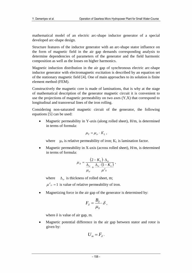
Boundary conditions, which are taken into account to solve the field problem, are
the following [4] :
- boundary conditions of the first kind on external (upper and lower)
borders of the simulated area (homogeneous) (see Fig. 3)are given by:
constU Bm .
- boundary conditions of the second kind on external (left and right)
borders of the simulated area (see Fig. 3) are determined in terms of:
0
B
m
n
U.
The last condition is true, when moving away the borders of the area for a
considerable distance from the field source.
It is necessary to maintain the continuity condition of magnetic scalar potential
and equality of normal and tangential derivatives on the interfacial area. In finite
element method these conditions are met automatically. Computational area of the
magnetic field studies with boundary conditions is shown in Fig. 3.
Figure 3
Research area of the magnetic field
Y. Dementyev et al. Operation of Gearless Micro Hydropower Plant for Small Water-Course
– 160 –
3 Results of Simulation Studies
3.1 Geometrical Parameters Impact on Machine Performance
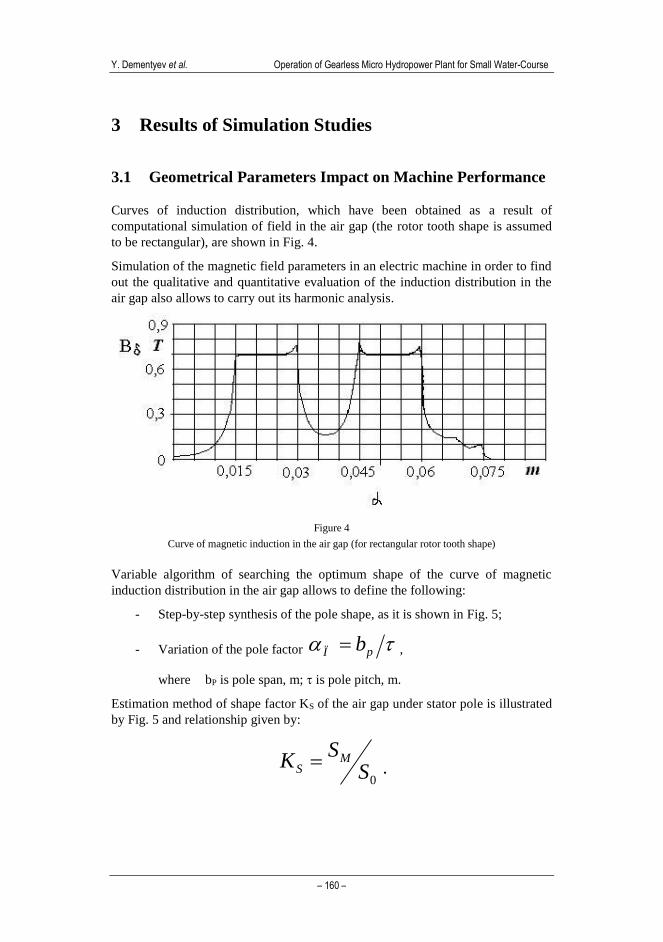
Curves of induction distribution, which have been obtained as a result of
computational simulation of field in the air gap (the rotor tooth shape is assumed
to be rectangular), are shown in Fig. 4.
Simulation of the magnetic field parameters in an electric machine in order to find
out the qualitative and quantitative evaluation of the induction distribution in the
air gap also allows to carry out its harmonic analysis.
Figure 4
Curve of magnetic induction in the air gap (for rectangular rotor tooth shape)
Variable algorithm of searching the optimum shape of the curve of magnetic
induction distribution in the air gap allows to define the following:
- Step-by-step synthesis of the pole shape, as it is shown in Fig. 5;
- Variation of the pole factor pÏ b ,
where bP is pole span, m; is pole pitch, m.
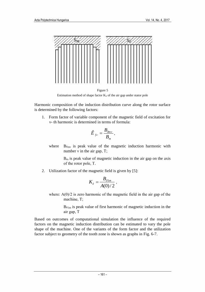
Estimation method of shape factor KS of the air gap under stator pole is illustrated
by Fig. 5 and relationship given by:
0SS
K MS .
Acta Polytechnica Hungarica Vol. 14, No. 4, 2017
– 161 –
Figure 5
Estimation method of shape factor KS of the air gap under stator pole
Harmonic composition of the induction distribution curve along the rotor surface
is determined by the following factors:
1. Form factor of variable component of the magnetic field of excitation for
ν- th harmonic is determined in terms of formula:
m
mf
B
BÊ
,
where Bmν is peak value of the magnetic induction harmonic with
number ν in the air gap, Т;
Bm is peak value of magnetic induction in the air gap on the axis
of the rotor pole, Т.
2. Utilization factor of the magnetic field is given by [5]:
2/)0(
1
A
BK m
è ,
where: А(0)/2 is zero harmonic of the magnetic field in the air gap of the
machine, Т;
B1m is peak value of first harmonic of magnetic induction in the
air gap, Т
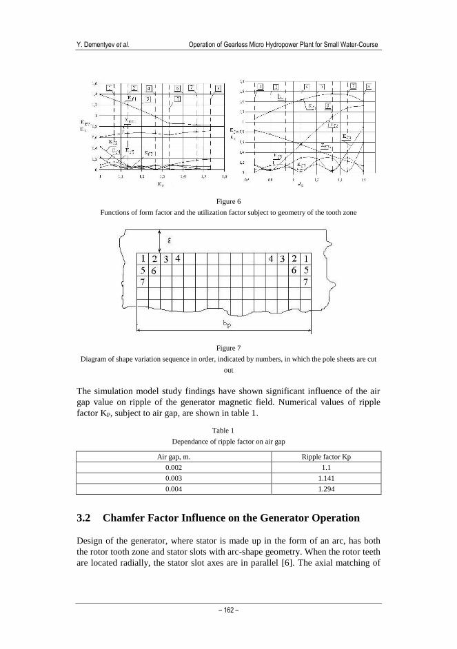
Based on outcomes of computational simulation the influence of the required
factors on the magnetic induction distribution can be estimated to vary the pole
shape of the machine. One of the variants of the form factor and the utilization
factor subject to geometry of the tooth zone is shown as graphs in Fig. 6-7.
Y. Dementyev et al. Operation of Gearless Micro Hydropower Plant for Small Water-Course
– 162 –
Figure 6
Functions of form factor and the utilization factor subject to geometry of the tooth zone
Figure 7
Diagram of shape variation sequence in order, indicated by numbers, in which the pole sheets are cut
out
The simulation model study findings have shown significant influence of the air
gap value on ripple of the generator magnetic field. Numerical values of ripple
factor KP, subject to air gap, are shown in table 1.
Table 1
Dependance of ripple factor on air gap
Air gap, m. Ripple factor Kp
0.002 1.1
0.003 1.141
0.004 1.294
3.2 Chamfer Factor Influence on the Generator Operation
Design of the generator, where stator is made up in the form of an arc, has both
the rotor tooth zone and stator slots with arc-shape geometry. When the rotor teeth
are located radially, the stator slot axes are in parallel [6]. The axial matching of
Acta Polytechnica Hungarica Vol. 14, No. 4, 2017
– 163 –
stator and rotor teeth, which are located in the middle of the arc, should be noted.
When moving along the rotor tooth axis to the edge of the arc, the slot chamfer
angle is increasing (Fig. 8, 9). It means that the slot chamfer angle is not a
constant, as in standard ac machines, but a variable that is altered 0 to its
maximum value [7]. Hereby the influence of the chamfer on the EMF of the
armature winding should be studied.
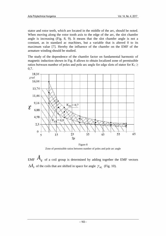
The study of the dependence of the chamfer factor on fundamental harmonic of
magnetic induction shown in Fig. 8 allows to obtain localized zone of permissible
ratios between number of poles and pole arc angle for edge slots of stator for КC ≥
0,7.
Figure 8
Zone of permissible ratios between number of poles and pole arc angle
EMF qÅ of a coil group is determined by adding together the EMF vectors
êÅ of the coils that are shifted in space for angle iñê (Fig. 10).
Y. Dementyev et al. Operation of Gearless Micro Hydropower Plant for Small Water-Course
– 164 –
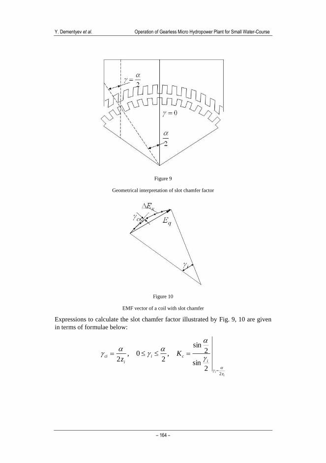
Figure 9
Geometrical interpretation of slot chamfer factor
Figure 10
EMF vector of a coil with slot chamfer
Expressions to calculate the slot chamfer factor illustrated by Fig. 9, 10 are given
in terms of formulae below:
ii
z
ici
i
ci Kz
22
sin
2sin
,2
0,2
Acta Polytechnica Hungarica Vol. 14, No. 4, 2017
– 165 –
20
2
0
2
0
2
0
cosln2
sin2
sin2sin2
2sin
2sin
2sin
2sin
zctgzecK
z
dz
x
dxdK
c
ii
c
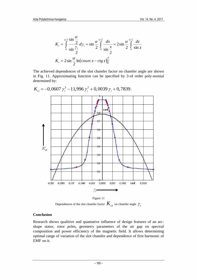
The achieved dependences of the slot chamfer factor on chamfer angle are shown
in Fig. 11. Approximating function can be specified by 3-rd order poly-nomial
determined by:
3 20,0607 11,996 0,0039 0,7839сi i i iK .
Figure 11
Dependences of the slot chamfer factor ciK on chamfer angle i
Conclusion
Research shows qualitive and quantative influence of design features of an arc-
shape stator, rotor poles, geometry parameters of the air gap on spectral
composition and power efficiency of the magnetic field. It allows determining
optimal range of variation of the slot chamfer and dependence of first harmonic of
EMF on it.
Y. Dementyev et al. Operation of Gearless Micro Hydropower Plant for Small Water-Course
– 166 –
Analysis of the obtained calculated and simulation data shows that the generator
output parameters (form factor, utilization factor, ripple factor) are influenced by
geometrical parameters of the machine. In addition, the impact of the the air gap
on the ripple factor is found to be significant.
Functional dependence of the slot chamfer factor on chamfer angle has been
found, which simplifies the problem of choosing reasonable, in terms of
efficiency, design parameters of the generator of a micro hydropower plant.
Acknowledgments
The research is funded from Tomsk Polytechnic University Competitiveness
Enhancement Program grant, Project Number TPU CEP_IPE_97\2017.
References
[1] Müller, G.a , Kauppert, K.b Performance characteristics of water wheels.
- Journal of Hydraulic Research. Volume 42, Issue 5, 2004, Pages 451-460.
[2] Anagnostopoulos, J.S. , Papantonis, D.E. Optimal sizing of a run-of-river
small hydropower plant. - Energy Conversion and Management. Volume
48, Issue 10, October 2007, Pages 2663-2670.
[3] Müller, G., Denchfield, S., Marth, R., Shelmerdine, R. Stream wheels for
applications in shallow and deep water (2007) Proc 32nd IAHR Congress,
Venice C (2c, Paper 291).
[4] Generator for micro power plant// V. M. Kuzmin, G. A. Sedov, V. I.
Suzdorf /Patent 39918 of Russian Federation, MPK H02P7/29. publ. in
bull. №23, 2004 (in Russian).
[5] Suzdorf V.I. Simulation of voltage sources for autonomous power supply
system. Education and science: actual state and outlook// Proceedings of
conference NTK 31st of July 2014: in 6 vol. Vol.3. Tambov: «Consulting
company Yukom», 2014.- p.128-130 (in Russian).
[6] Victor I. Suzdorf, Aleksandr S. Meshkov, Yuri N. Dementyev and Dmitriy
A. Kaftasyev Energy efficiency improvement of medical electric tools and
devices// The 2nd International Youth Forum “Smart Grids”, MATEC Web
of Conferences, Volume 19, 2014. -Published online: 15 December 2014.
[7] Quaranta, E. , Revelli, R. Performance characteristics, power losses and
mechanical power estimation for a breastshot water wheel. – Energy.
Volume 87, 1 July 2015, Pages 315-325.