Embed Size (px)
Citation preview
DEPARTMENT OF ENERGY ENERGY UTILIZATION MANAGEMENT BUREAU
Micro-hydropower Plant
Site Completion Test Manual
June 2009
MHP – 4

This manual was developed by the Department of Energy (DOE) through the technical assistance under the Project on “Sustainability Improvement of Renewable Energy Development for Village Electrification in the Philippines” which was provided by the Japan International Cooperation Agency (JICA).
Table of Contents
1 General......................................................................................................................... 1
2 Scope............................................................................................................................ 1
3 Objectives .................................................................................................................... 1
4 Implementation structure ............................................................................................. 1
4.1 Management structure ...................................................................................... 1
4.2 Roles and responsibilities ................................................................................. 2
5 Test Instruction ............................................................................................................ 3
5.1 Civil and metal structures ................................................................................. 3 5.1.1 Common ....................................................................................................... 3 5.1.2 Gate and stoplog ........................................................................................... 3 5.1.3 Concrete structures ....................................................................................... 4 5.1.4 Operation & maintenance manuals/instructions........................................... 4 5.1.5 Documents to be prepared ............................................................................ 4
5.2 Electro-mechanical equipment ......................................................................... 4 5.2.1 Inlet valve and drain valve for penstock water............................................. 4 5.2.2 Comprehensive test ...................................................................................... 4 5.2.3 Operation & maintenance manuals/instructions........................................... 6 5.2.4 Documents to be prepared ............................................................................ 6
5.3 Transmission and distribution facilities............................................................ 7 5.3.1 Common ....................................................................................................... 7 5.3.2 Operation and maintenance manuals/instructions ........................................ 7 5.3.3 Documents to be provided............................................................................ 7
6 Amendment of the manual........................................................................................... 8

LIST OF ANNEXES
ANNEX 1 : Appearance checklist for civil and metal structures ANNEX 2 : Example procedures of comprehensive test for
electro-mechanical equipment
1
1 General
This manual is intended to specify standardized test items and procedures for the completion test of micro-hydropower plants. Accordingly, an actual on-site test was conducted taking into account the real conditions of the plants which served as the reference basis for the test instructions and record forms shown in this manual.
2 Scope
This manual shall be used for the on-site completion test conducted in conjunction with the new construction of micro-hydropower plants. Users also may utilize this manual for performance tests after the rehabilitation and upgrade of existing micro-hydropower plants by choosing the appropriate test items.
3 Objectives
The objectives of this manual are: (1) to verify if the installed equipment meets the requirements, and (2) to secure the safety of the equipment and people after commissioning through
the precise implementation of a field performance test.
4 Implementation structure
4.1 Management structure
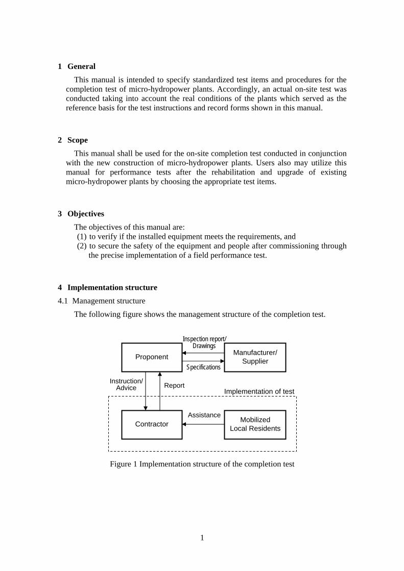
The following figure shows the management structure of the completion test.
Figure 1 Implementation structure of the completion test
Proponent
Contractor Mobilized
Local Residents
Assistance
ReportInstruction/
Advice Implementation of test
Manufacturer/ Supplier
Inspection report/ Drawings
Specifications
2
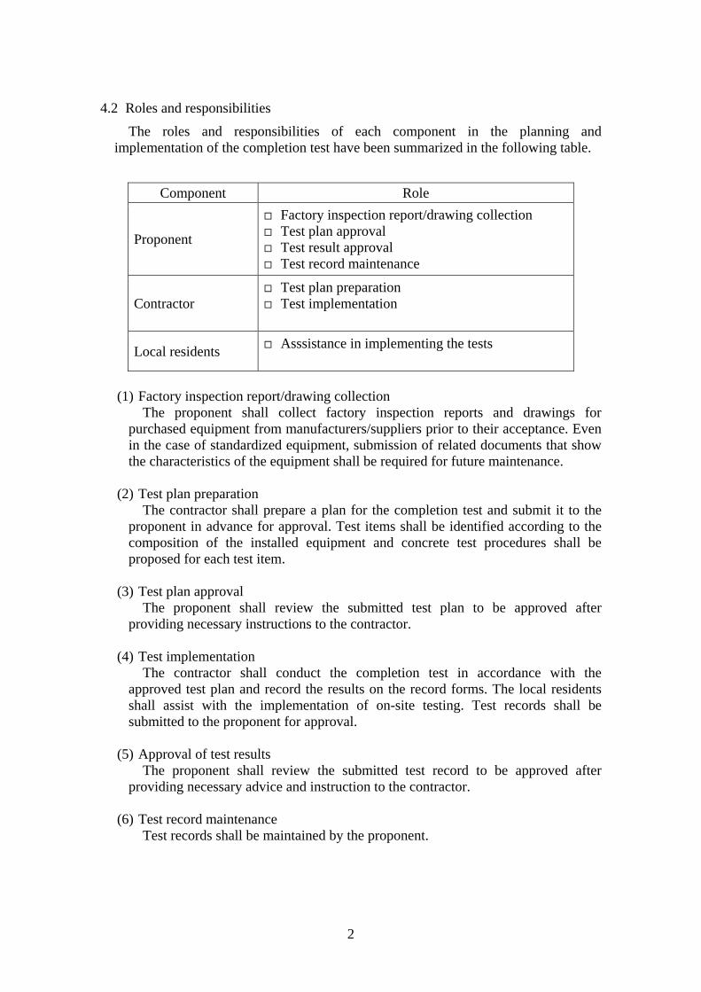
4.2 Roles and responsibilities
The roles and responsibilities of each component in the planning and implementation of the completion test have been summarized in the following table.
(1) Factory inspection report/drawing collection
The proponent shall collect factory inspection reports and drawings for purchased equipment from manufacturers/suppliers prior to their acceptance. Even in the case of standardized equipment, submission of related documents that show the characteristics of the equipment shall be required for future maintenance.
(2) Test plan preparation
The contractor shall prepare a plan for the completion test and submit it to the proponent in advance for approval. Test items shall be identified according to the composition of the installed equipment and concrete test procedures shall be proposed for each test item.
(3) Test plan approval
The proponent shall review the submitted test plan to be approved after providing necessary instructions to the contractor.
(4) Test implementation
The contractor shall conduct the completion test in accordance with the approved test plan and record the results on the record forms. The local residents shall assist with the implementation of on-site testing. Test records shall be submitted to the proponent for approval.
(5) Approval of test results
The proponent shall review the submitted test record to be approved after providing necessary advice and instruction to the contractor.
(6) Test record maintenance
Test records shall be maintained by the proponent.
Component Role
Proponent
Factory inspection report/drawing collection Test plan approval Test result approval Test record maintenance
Contractor Test plan preparation Test implementation
Local residents Asssistance in implementing the tests
3
5 Test Instruction
5.1 Civil and metal structures
5.1.1 Common
(1) Appearance check
Civil and metal structures shall be inspected visually to identify any defects and/or evidence of water leakage. Examples of checklist items are shown in ANNEX1.
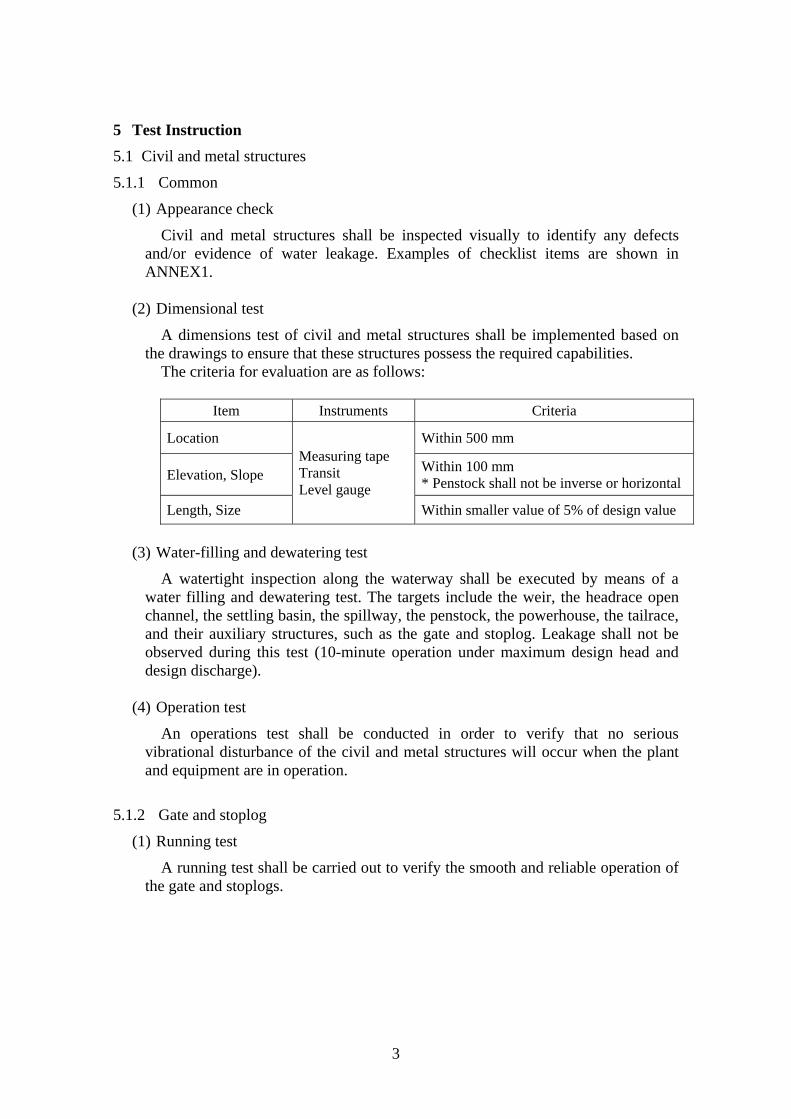
(2) Dimensional test
A dimensions test of civil and metal structures shall be implemented based on the drawings to ensure that these structures possess the required capabilities.
The criteria for evaluation are as follows:
Item Instruments Criteria
Location Within 500 mm
Elevation, Slope Within 100 mm * Penstock shall not be inverse or horizontal
Length, Size
Measuring tape Transit Level gauge
Within smaller value of 5% of design value
(3) Water-filling and dewatering test
A watertight inspection along the waterway shall be executed by means of a water filling and dewatering test. The targets include the weir, the headrace open channel, the settling basin, the spillway, the penstock, the powerhouse, the tailrace, and their auxiliary structures, such as the gate and stoplog. Leakage shall not be observed during this test (10-minute operation under maximum design head and design discharge).
(4) Operation test
An operations test shall be conducted in order to verify that no serious vibrational disturbance of the civil and metal structures will occur when the plant and equipment are in operation.
5.1.2 Gate and stoplog
(1) Running test
A running test shall be carried out to verify the smooth and reliable operation of the gate and stoplogs.
4
5.1.3 Concrete structures
(1) Crack inspection
No cracks larger than 0.4 mm shall be allowed on the concrete structures through which water is run such as the weir, the headrace open channel, the settling basin, the spillway, and the tailrace. Photographs and sketches are useful for monitoring development of the cracks.
5.1.4 Operation & maintenance manuals/instructions
The contractor shall submit operation and maintenance manuals/instructions. Methods and frequency of inspection, repair and maintenance (including painting of penstock, gate and screen, sand flushing valve etc.) shall be described in the manuals/instructions.
5.1.5 Documents to be prepared
The contractor shall provide the following documents one week prior to the completion test.
(1) As-built drawings (layout, major structures)
(2) Head-loss calculation
(3) Maximum output power calculation
5.2 Electro-mechanical equipment
5.2.1 Inlet valve and drain valve for penstock water
After the inlet and drain valve for the penstock have been installed, and before putting the unit into service, the following performance tests shall be carried out by the contractor.
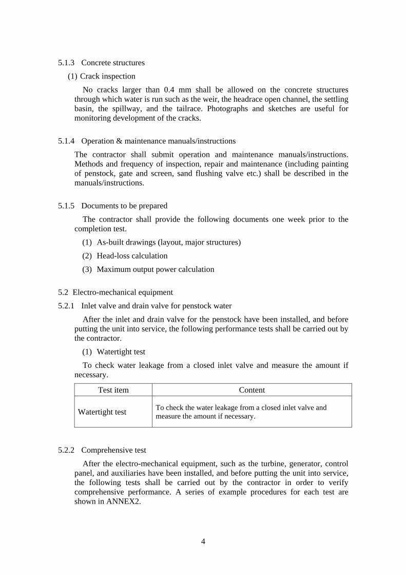
(1) Watertight test
To check water leakage from a closed inlet valve and measure the amount if necessary.
Test item Content
Watertight test To check the water leakage from a closed inlet valve and measure the amount if necessary.
5.2.2 Comprehensive test
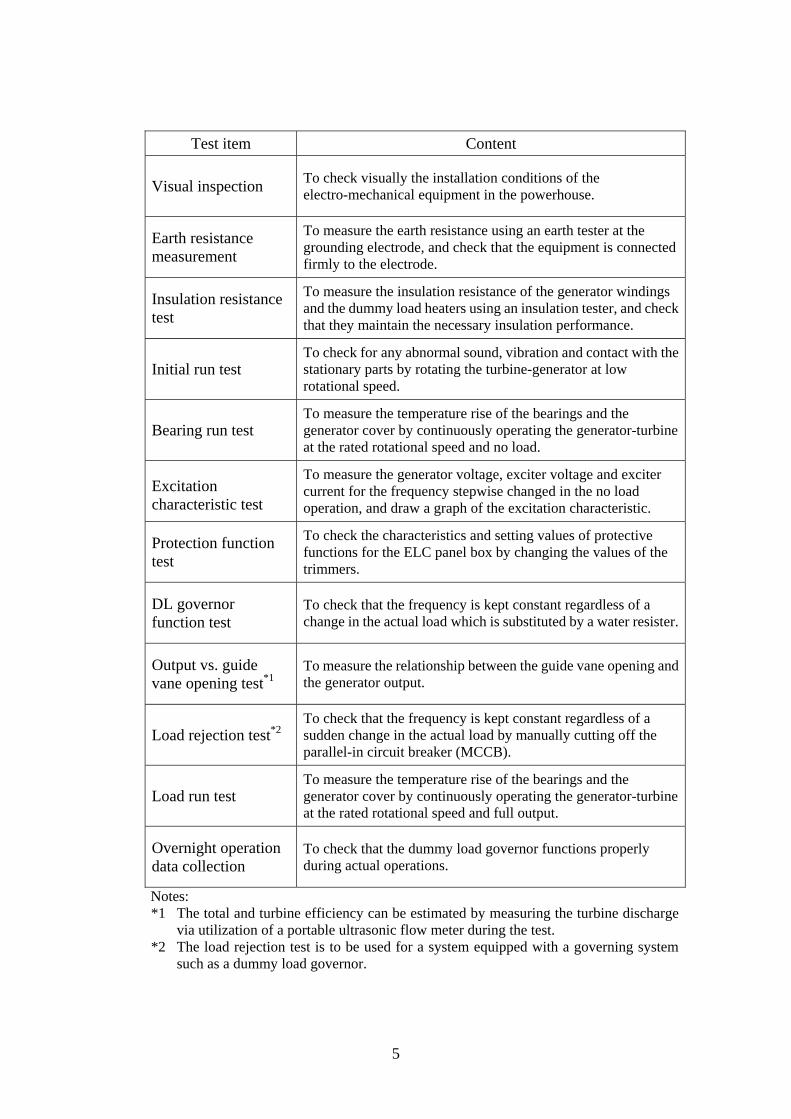
After the electro-mechanical equipment, such as the turbine, generator, control panel, and auxiliaries have been installed, and before putting the unit into service, the following tests shall be carried out by the contractor in order to verify comprehensive performance. A series of example procedures for each test are shown in ANNEX2.
5
Test item Content
Visual inspection To check visually the installation conditions of the electro-mechanical equipment in the powerhouse.
Earth resistance measurement
To measure the earth resistance using an earth tester at the grounding electrode, and check that the equipment is connected firmly to the electrode.
Insulation resistance test
To measure the insulation resistance of the generator windings and the dummy load heaters using an insulation tester, and check that they maintain the necessary insulation performance.
Initial run test To check for any abnormal sound, vibration and contact with the stationary parts by rotating the turbine-generator at low rotational speed.
Bearing run test To measure the temperature rise of the bearings and the generator cover by continuously operating the generator-turbine at the rated rotational speed and no load.
Excitation characteristic test
To measure the generator voltage, exciter voltage and exciter current for the frequency stepwise changed in the no load operation, and draw a graph of the excitation characteristic.
Protection function test
To check the characteristics and setting values of protective functions for the ELC panel box by changing the values of the trimmers.
DL governor function test
To check that the frequency is kept constant regardless of a change in the actual load which is substituted by a water resister.
Output vs. guide vane opening test*1
To measure the relationship between the guide vane opening and the generator output.
Load rejection test*2 To check that the frequency is kept constant regardless of a sudden change in the actual load by manually cutting off the parallel-in circuit breaker (MCCB).
Load run test To measure the temperature rise of the bearings and the generator cover by continuously operating the generator-turbine at the rated rotational speed and full output.
Overnight operation data collection
To check that the dummy load governor functions properly during actual operations.
Notes: *1 The total and turbine efficiency can be estimated by measuring the turbine discharge
via utilization of a portable ultrasonic flow meter during the test. *2 The load rejection test is to be used for a system equipped with a governing system
such as a dummy load governor.
6
5.2.3 Operation & maintenance manuals/instructions
The contractor shall submit operation and maintenance manuals/instructions. Assembling and disassembling methods, maintenance period, and the interval of
greasing, etc. for the following equipment and devices is described in the manuals/instructions.
(1) Turbine
(2) Generator
(3) Inlet valve
(4) Driving system
(5) Governing system (Electronic Load Controller: ELC)
(6) Automatic voltage regulator (AVR)
(7) Generator panel
5.2.4 Documents to be prepared
The contractor shall provide the following documents.
(1) Single line diagram – main & control circuits
(2) Power plant equipment layout drawings
(3) Specifications and generator panel drawing
(4) Unit control & protection system diagram
(5) Drawings of the dummy load heater
(6) Drawings of the inlet valve
(7) Drawings of the connecting pipe
(8) Connection diagrams of the generator panel
(9) Connection diagrams of the AVR
(10) Connection diagrams of the governor
(11) Connection diagrams of the control system
(12) Efficiency and output curve of the turbine
(13) Efficiency curves of the generator
(14) Test reports for all equipment/devices
(15) List of tools and spare parts
(16) Operation and maintenance manuals/instructions for all equipment/devices
7
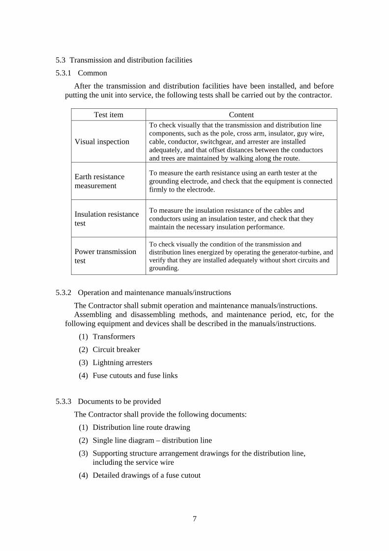
5.3 Transmission and distribution facilities
5.3.1 Common
After the transmission and distribution facilities have been installed, and before putting the unit into service, the following tests shall be carried out by the contractor.
Test item Content
Visual inspection
To check visually that the transmission and distribution line components, such as the pole, cross arm, insulator, guy wire, cable, conductor, switchgear, and arrester are installed adequately, and that offset distances between the conductors and trees are maintained by walking along the route.
Earth resistance measurement
To measure the earth resistance using an earth tester at the grounding electrode, and check that the equipment is connected firmly to the electrode.
Insulation resistance test
To measure the insulation resistance of the cables and conductors using an insulation tester, and check that they maintain the necessary insulation performance.
Power transmission test
To check visually the condition of the transmission and distribution lines energized by operating the generator-turbine, and verify that they are installed adequately without short circuits and grounding.
5.3.2 Operation and maintenance manuals/instructions
The Contractor shall submit operation and maintenance manuals/instructions. Assembling and disassembling methods, and maintenance period, etc, for the
following equipment and devices shall be described in the manuals/instructions.
(1) Transformers
(2) Circuit breaker
(3) Lightning arresters
(4) Fuse cutouts and fuse links
5.3.3 Documents to be provided
The Contractor shall provide the following documents:
(1) Distribution line route drawing
(2) Single line diagram – distribution line
(3) Supporting structure arrangement drawings for the distribution line, including the service wire
(4) Detailed drawings of a fuse cutout

8
(5) Detailed drawings of lightning arresters
(6) Specifications and drawings of conductors/cables
(7) Specifications and drawings of insulators and hardware (cross-arm, strap, u-bolts, bands, etc.)
(8) Test reports for all equipment/devices
(9) List of tools and spare parts
(10) Operation and maintenance manuals/instructions for all equipment/device
6 Amendment of the manual
The DOE shall review this manual annually, and amend it, if necessary, according to the surrounding circumstances in rural electrification of the country. The amended manual shall be fully authorized among the DOE and approved by Director of Energy Utilization Management Bureau of the DOE.
i
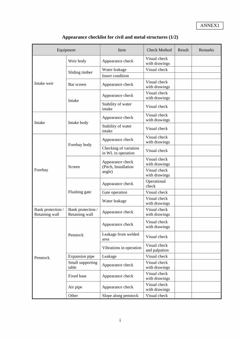
Appearance checklist for civil and metal structures (1/2)
Equipment Item Check Method Result Remarks
Weir body Appearance check Visual check with drawings
Water leakage Visual check Sliding timber
Insert condition
Bar screen Appearance check Visual check with drawings
Appearance check Visual check with drawings
Intake weir
Intake Stability of water intake
Visual check
Appearance check Visual check with drawings
Intake Intake body Stability of water intake
Visual check
Appearance check Visual check with drawings
Forebay body Checking of variation in WL in operation
Visual check
Visual check with drawings
Screen Appearance check (Pitch, Installation angle) Visual check
with drawings
Appearance check Operational check
Gate operation Visual check
Forebay
Flushing gate
Water leakage Visual check with drawings
Bank protection / Retaining wall
Bank protection / Retaining wall
Appearance check Visual check with drawings
Appearance check Visual check with drawings
Leakage from welded area
Visual check
Penstock
Vibrations in operationVisual check and palpation
Expansion pipe Leakage Visual check
Small supporting table
Appearance check Visual check with drawings
Fixed base Appearance check Visual check with drawings
Air pipe Appearance check Visual check with drawings
Penstock
Other Slope along penstock Visual check
ANNEX1
ii
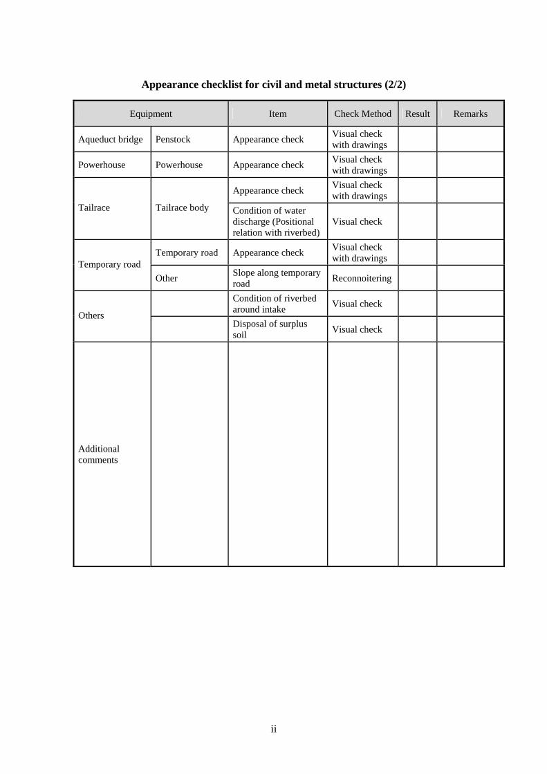
Appearance checklist for civil and metal structures (2/2)
Equipment Item Check Method Result Remarks
Aqueduct bridge Penstock Appearance check Visual check with drawings
Powerhouse Powerhouse Appearance check Visual check with drawings
Appearance check Visual check with drawings
Tailrace Tailrace body Condition of water discharge (Positional relation with riverbed)
Visual check
Temporary road Appearance check Visual check with drawings
Temporary road
Other Slope along temporary road
Reconnoitering
Condition of riverbed around intake
Visual check
Others
Disposal of surplus soil
Visual check
Additional comments
i
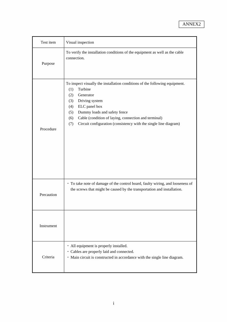
Test item Visual inspection
Purpose
To verify the installation conditions of the equipment as well as the cable
connection.
Procedure
To inspect visually the installation conditions of the following equipment.
(1) Turbine
(2) Generator
(3) Driving system
(4) ELC panel box
(5) Dummy loads and safety fence
(6) Cable (condition of laying, connection and terminal)
(7) Circuit configuration (consistency with the single line diagram)
Precaution
・ To take note of damage of the control board, faulty wiring, and looseness of
the screws that might be caused by the transportation and installation.
Instrument
Criteria
・ All equipment is properly installed.
・ Cables are properly laid and connected.
・ Main circuit is constructed in accordance with the single line diagram.
ANNEX2

ii
Test item Earth resistance measurement
Purpose
To verify the earth resistance of the grounding electrode and connections
between the electrode and equipment
Procedure
1. Earth resistance measurement
(1) To drive the auxiliary earthing rods P and C deep into the ground, at
intervals of 5 – 10 m (straight line) from the measurement object E
(2) Battery check
(3) Earth voltage check
(4) Auxiliary earthing resistance check
(5) Earth resistance measurement
2. Earthing connection check
(1) To set the tester to “connection check”
(2) To connect the two (2) lead wires to the grounding electrode and the
grounding terminal of the following equipment respectively
・ Generator stator winding
・ Base flame
・ ELC panel box
(3) To verify the connection of the grounding cable by the circuit tester
Precaution
Instrument
・ Earth tester
・ Circuit tester
Criteria
・ Earth resistance of the grounding electrode is at a sufficiently low setting
・ The equipment’s grounding terminal is firmly connected to the grounding
electrode.
iii
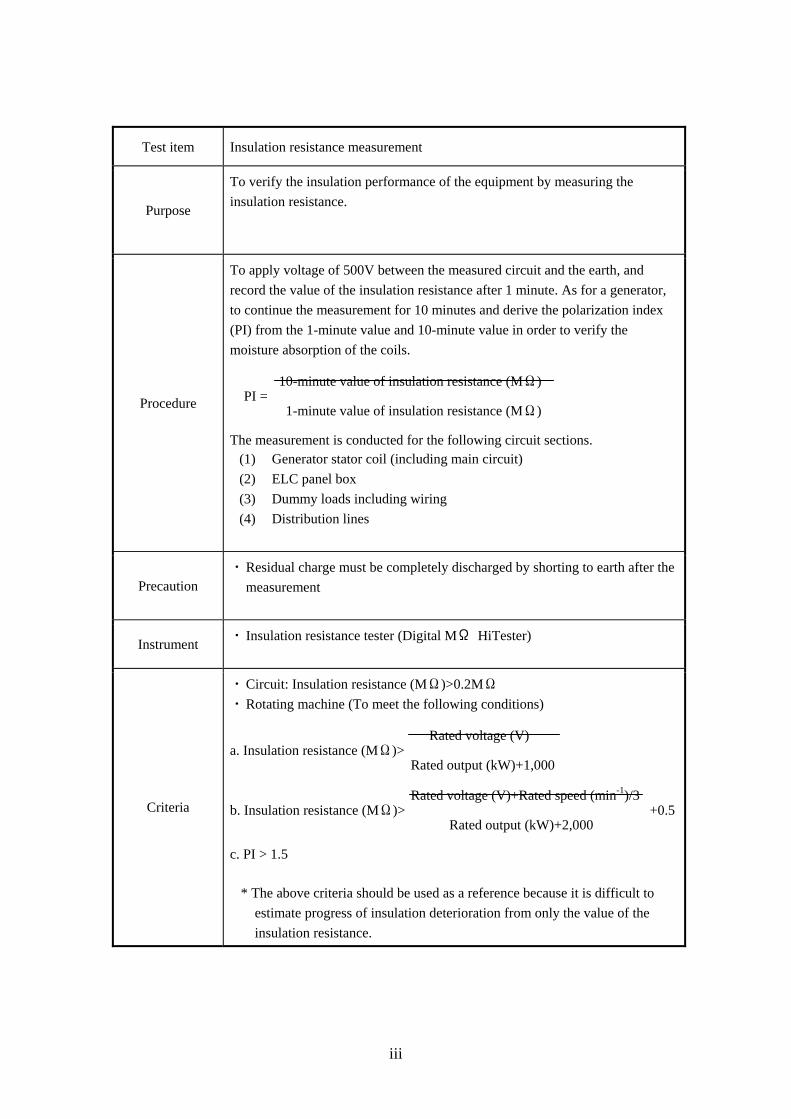
Test item Insulation resistance measurement
Purpose
To verify the insulation performance of the equipment by measuring the
insulation resistance.
Procedure
To apply voltage of 500V between the measured circuit and the earth, and
record the value of the insulation resistance after 1 minute. As for a generator,
to continue the measurement for 10 minutes and derive the polarization index
(PI) from the 1-minute value and 10-minute value in order to verify the
moisture absorption of the coils. 10-minute value of insulation resistance (MΩ)
PI = 1-minute value of insulation resistance (MΩ) The measurement is conducted for the following circuit sections.
(1) Generator stator coil (including main circuit)
(2) ELC panel box
(3) Dummy loads including wiring
(4) Distribution lines
Precaution ・ Residual charge must be completely discharged by shorting to earth after the
measurement
Instrument ・ Insulation resistance tester (Digital MΩ HiTester)
Criteria
・ Circuit: Insulation resistance (MΩ)>0.2MΩ
・ Rotating machine (To meet the following conditions)
Rated voltage (V) a. Insulation resistance (MΩ)>
Rated output (kW)+1,000
Rated voltage (V)+Rated speed (min-1)/3 b. Insulation resistance (MΩ)> +0.5
Rated output (kW)+2,000 c. PI > 1.5
* The above criteria should be used as a reference because it is difficult to
estimate progress of insulation deterioration from only the value of the
insulation resistance.
iv
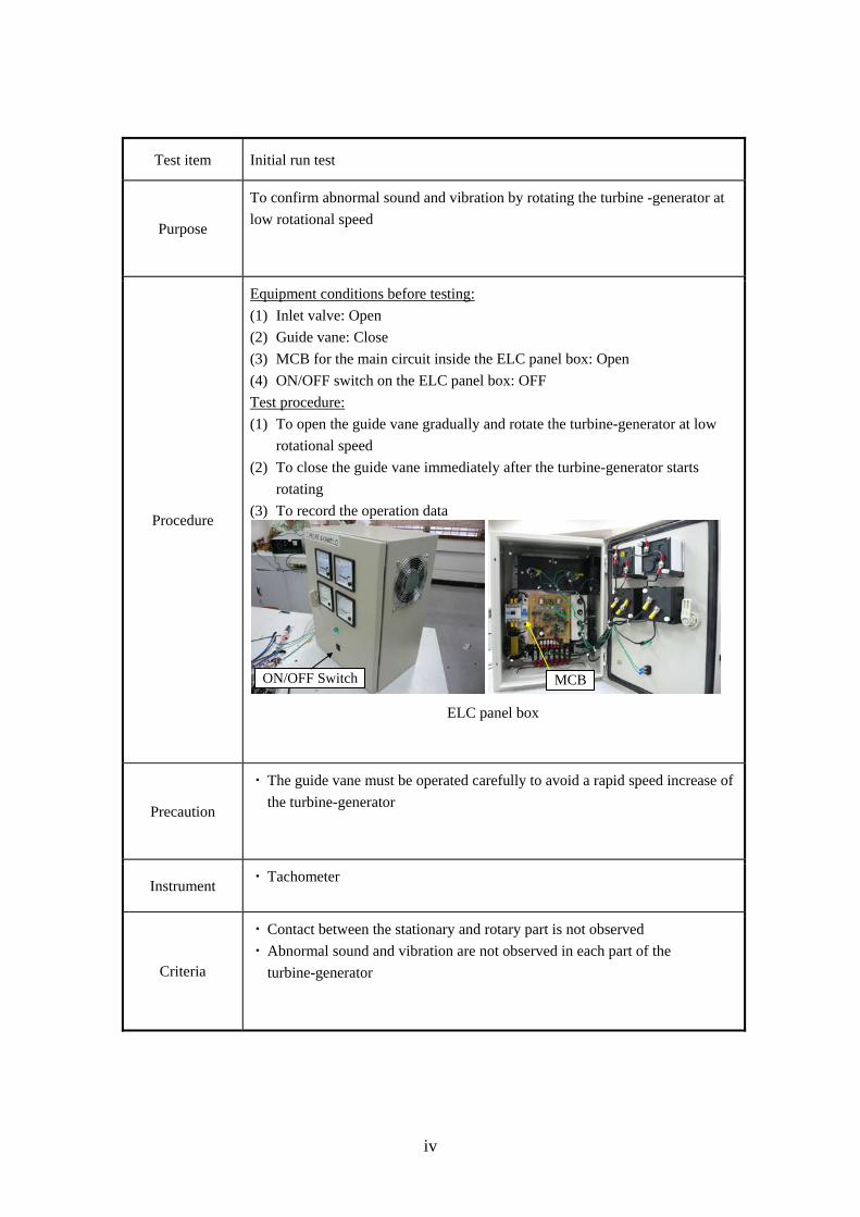
Test item Initial run test
Purpose
To confirm abnormal sound and vibration by rotating the turbine -generator at
low rotational speed
Procedure
Equipment conditions before testing:
(1) Inlet valve: Open
(2) Guide vane: Close
(3) MCB for the main circuit inside the ELC panel box: Open
(4) ON/OFF switch on the ELC panel box: OFF
Test procedure:
(1) To open the guide vane gradually and rotate the turbine-generator at low
rotational speed
(2) To close the guide vane immediately after the turbine-generator starts
rotating
(3) To record the operation data
Precaution
・ The guide vane must be operated carefully to avoid a rapid speed increase of
the turbine-generator
Instrument ・ Tachometer
Criteria
・ Contact between the stationary and rotary part is not observed
・ Abnormal sound and vibration are not observed in each part of the
turbine-generator
ELC panel box
ON/OFF Switch MCB
v
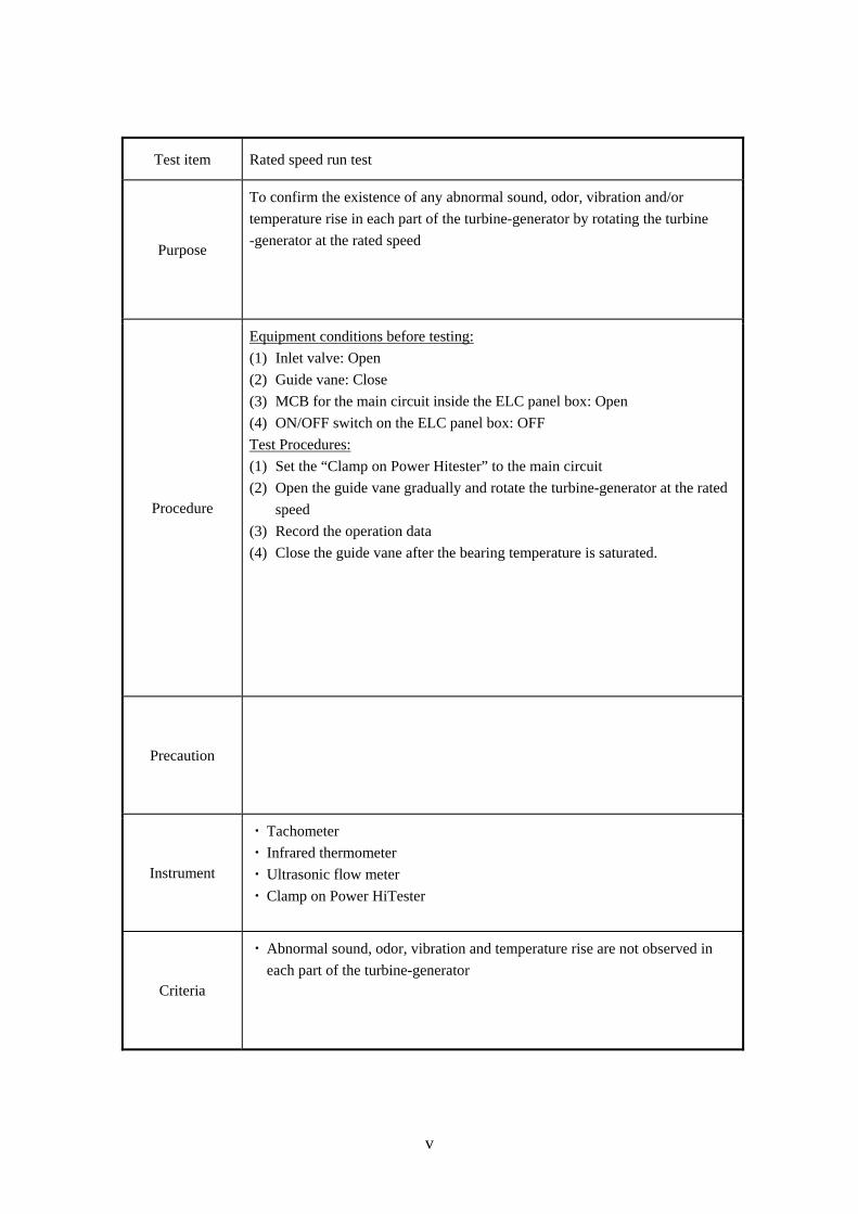
Test item Rated speed run test
Purpose
To confirm the existence of any abnormal sound, odor, vibration and/or
temperature rise in each part of the turbine-generator by rotating the turbine
-generator at the rated speed
Procedure
Equipment conditions before testing:
(1) Inlet valve: Open
(2) Guide vane: Close
(3) MCB for the main circuit inside the ELC panel box: Open
(4) ON/OFF switch on the ELC panel box: OFF
Test Procedures:
(1) Set the “Clamp on Power Hitester” to the main circuit
(2) Open the guide vane gradually and rotate the turbine-generator at the rated
speed
(3) Record the operation data
(4) Close the guide vane after the bearing temperature is saturated.
Precaution
Instrument
・ Tachometer
・ Infrared thermometer
・ Ultrasonic flow meter
・ Clamp on Power HiTester
Criteria
・ Abnormal sound, odor, vibration and temperature rise are not observed in
each part of the turbine-generator
vi
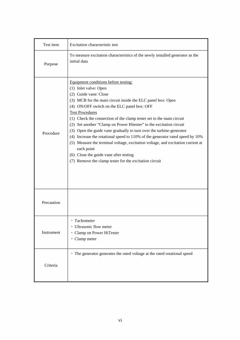
Test item Excitation characteristic test
Purpose
To measure excitation characteristics of the newly installed generator as the
initial data
Procedure
Equipment conditions before testing:
(1) Inlet valve: Open
(2) Guide vane: Close
(3) MCB for the main circuit inside the ELC panel box: Open
(4) ON/OFF switch on the ELC panel box: OFF
Test Procedures
(1) Check the connection of the clamp tester set to the main circuit
(2) Set another “Clamp on Power Hitester” to the excitation circuit
(3) Open the guide vane gradually to turn over the turbine-generator
(4) Increase the rotational speed to 110% of the generator rated speed by 10%
(5) Measure the terminal voltage, excitation voltage, and excitation current at
each point
(6) Close the guide vane after testing
(7) Remove the clamp tester for the excitation circuit
Precaution
Instrument
・ Tachometer
・ Ultrasonic flow meter
・ Clamp on Power HiTester
・ Clamp meter
Criteria
・ The generator generates the rated voltage at the rated rotational speed
vii
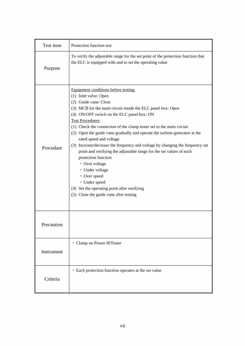
Test item Protection function test
Purpose
To verify the adjustable range for the set point of the protection function that
the ELC is equipped with and to set the operating value
Procedure
Equipment conditions before testing:
(1) Inlet valve: Open
(2) Guide vane: Close
(3) MCB for the main circuit inside the ELC panel box: Open
(4) ON/OFF switch on the ELC panel box: ON
Test Procedures:
(1) Check the connection of the clamp tester set to the main circuit
(2) Open the guide vane gradually and operate the turbine-generator at the
rated speed and voltage
(3) Increase/decrease the frequency and voltage by changing the frequency set
point and verifying the adjustable range for the set values of each
protection function
・ Over voltage
・ Under voltage
・ Over speed
・ Under speed
(4) Set the operating point after verifying
(5) Close the guide vane after testing
Precaution
Instrument
・ Clamp on Power HiTester
Criteria
・ Each protection function operates at the set value
viii
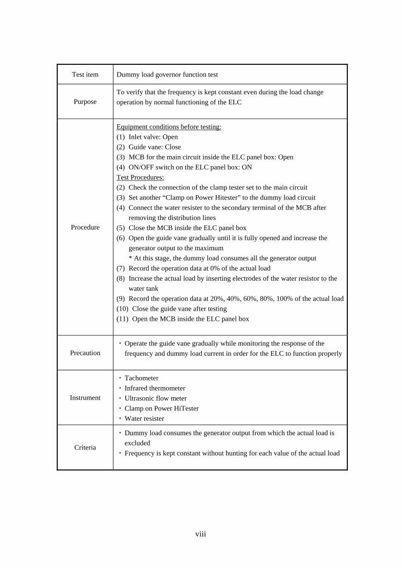
Test item Dummy load governor function test
Purpose To verify that the frequency is kept constant even during the load change
operation by normal functioning of the ELC
Procedure
Equipment conditions before testing:
(1) Inlet valve: Open
(2) Guide vane: Close
(3) MCB for the main circuit inside the ELC panel box: Open
(4) ON/OFF switch on the ELC panel box: ON
Test Procedures:
(2) Check the connection of the clamp tester set to the main circuit
(3) Set another “Clamp on Power Hitester” to the dummy load circuit
(4) Connect the water resister to the secondary terminal of the MCB after
removing the distribution lines
(5) Close the MCB inside the ELC panel box
(6) Open the guide vane gradually until it is fully opened and increase the
generator output to the maximum
* At this stage, the dummy load consumes all the generator output
(7) Record the operation data at 0% of the actual load
(8) Increase the actual load by inserting electrodes of the water resistor to the
water tank
(9) Record the operation data at 20%, 40%, 60%, 80%, 100% of the actual load
(10) Close the guide vane after testing
(11) Open the MCB inside the ELC panel box
Precaution ・ Operate the guide vane gradually while monitoring the response of the
frequency and dummy load current in order for the ELC to function properly
Instrument
・ Tachometer
・ Infrared thermometer
・ Ultrasonic flow meter
・ Clamp on Power HiTester
・ Water resister
Criteria
・ Dummy load consumes the generator output from which the actual load is
excluded
・ Frequency is kept constant without hunting for each value of the actual load
ix
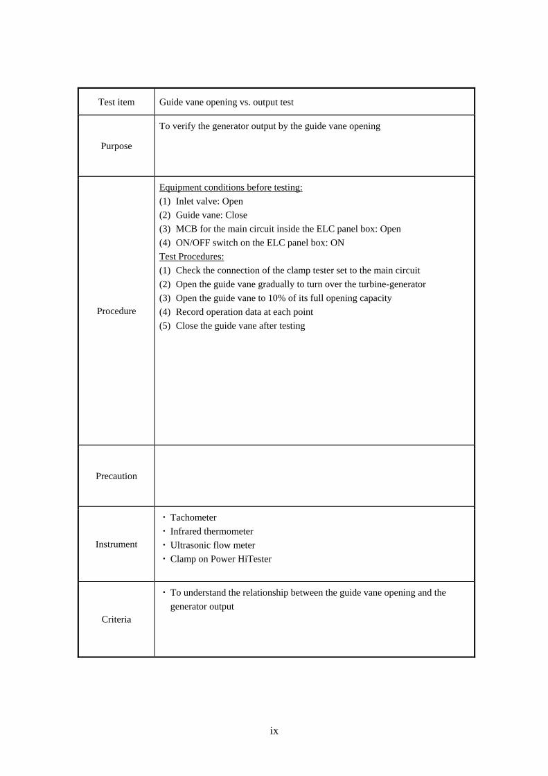
Test item Guide vane opening vs. output test
Purpose
To verify the generator output by the guide vane opening
Procedure
Equipment conditions before testing:
(1) Inlet valve: Open
(2) Guide vane: Close
(3) MCB for the main circuit inside the ELC panel box: Open
(4) ON/OFF switch on the ELC panel box: ON
Test Procedures:
(1) Check the connection of the clamp tester set to the main circuit
(2) Open the guide vane gradually to turn over the turbine-generator
(3) Open the guide vane to 10% of its full opening capacity
(4) Record operation data at each point
(5) Close the guide vane after testing
Precaution
Instrument
・ Tachometer
・ Infrared thermometer
・ Ultrasonic flow meter
・ Clamp on Power HiTester
Criteria
・ To understand the relationship between the guide vane opening and the
generator output
x
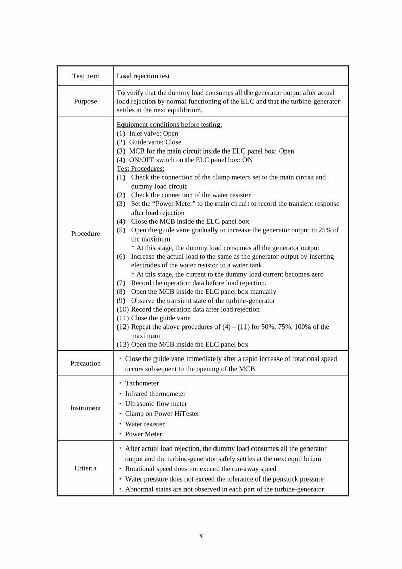
Test item Load rejection test
Purpose To verify that the dummy load consumes all the generator output after actual load rejection by normal functioning of the ELC and that the turbine-generator settles at the next equilibrium.
Procedure
Equipment conditions before testing: (1) Inlet valve: Open (2) Guide vane: Close (3) MCB for the main circuit inside the ELC panel box: Open (4) ON/OFF switch on the ELC panel box: ON Test Procedures: (1) Check the connection of the clamp meters set to the main circuit and
dummy load circuit (2) Check the connection of the water resister (3) Set the “Power Meter” to the main circuit to record the transient response
after load rejection (4) Close the MCB inside the ELC panel box (5) Open the guide vane gradually to increase the generator output to 25% of
the maximum * At this stage, the dummy load consumes all the generator output
(6) Increase the actual load to the same as the generator output by inserting electrodes of the water resistor to a water tank * At this stage, the current to the dummy load current becomes zero
(7) Record the operation data before load rejection. (8) Open the MCB inside the ELC panel box manually (9) Observe the transient state of the turbine-generator (10) Record the operation data after load rejection (11) Close the guide vane (12) Repeat the above procedures of (4) – (11) for 50%, 75%, 100% of the
maximum (13) Open the MCB inside the ELC panel box
Precaution ・ Close the guide vane immediately after a rapid increase of rotational speed
occurs subsequent to the opening of the MCB
Instrument
・ Tachometer
・ Infrared thermometer
・ Ultrasonic flow meter
・ Clamp on Power HiTester
・ Water resister
・ Power Meter
Criteria
・ After actual load rejection, the dummy load consumes all the generator
output and the turbine-generator safely settles at the next equilibrium
・ Rotational speed does not exceed the run-away speed
・ Water pressure does not exceed the tolerance of the penstock pressure
・ Abnormal states are not observed in each part of the turbine-generator
xi
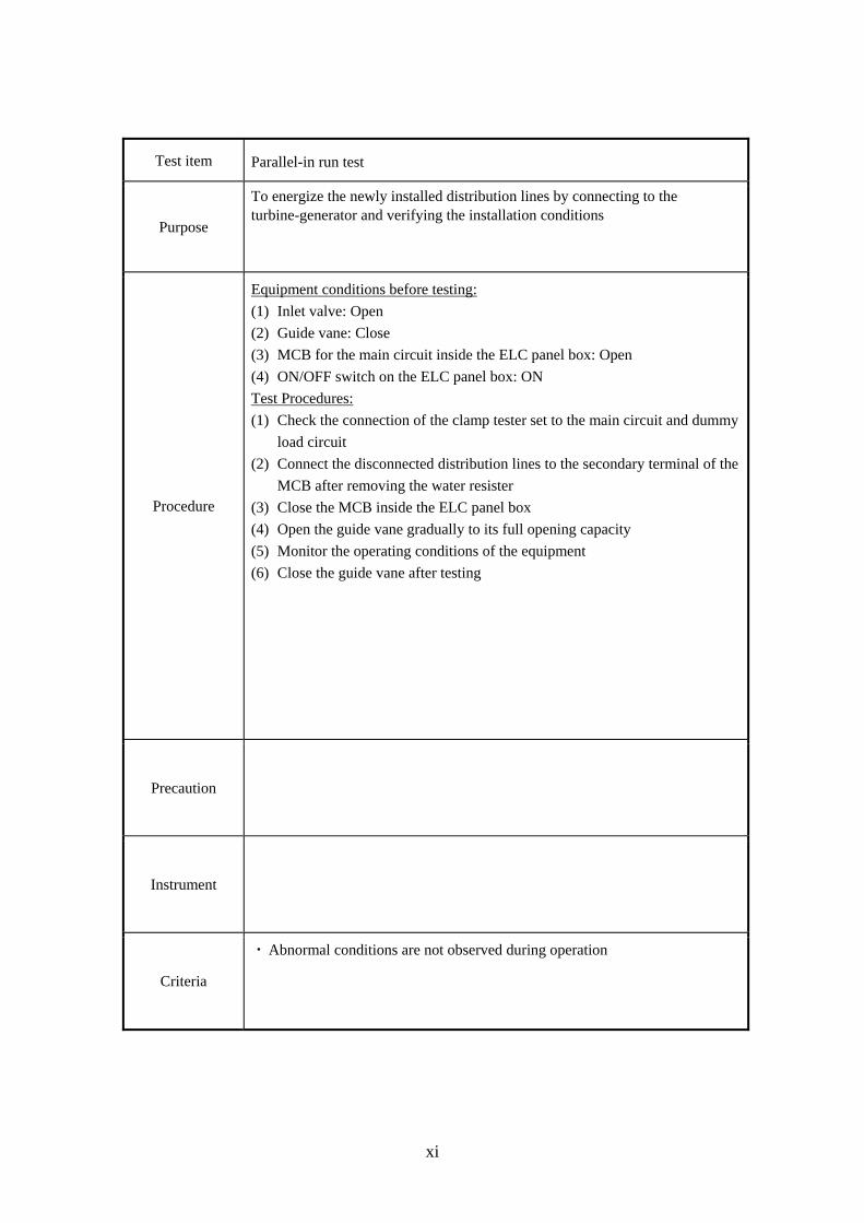
Test item Parallel-in run test
Purpose
To energize the newly installed distribution lines by connecting to the turbine-generator and verifying the installation conditions
Procedure
Equipment conditions before testing:
(1) Inlet valve: Open
(2) Guide vane: Close
(3) MCB for the main circuit inside the ELC panel box: Open
(4) ON/OFF switch on the ELC panel box: ON
Test Procedures:
(1) Check the connection of the clamp tester set to the main circuit and dummy
load circuit
(2) Connect the disconnected distribution lines to the secondary terminal of the
MCB after removing the water resister
(3) Close the MCB inside the ELC panel box
(4) Open the guide vane gradually to its full opening capacity
(5) Monitor the operating conditions of the equipment
(6) Close the guide vane after testing
Precaution
Instrument
Criteria
・ Abnormal conditions are not observed during operation
xii
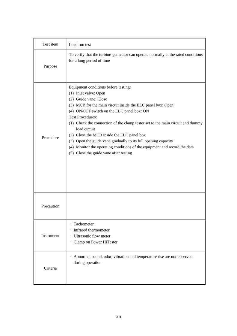
Test item Load run test
Purpose
To verify that the turbine-generator can operate normally at the rated conditions
for a long period of time
Procedure
Equipment conditions before testing:
(1) Inlet valve: Open
(2) Guide vane: Close
(3) MCB for the main circuit inside the ELC panel box: Open
(4) ON/OFF switch on the ELC panel box: ON
Test Procedures:
(1) Check the connection of the clamp tester set to the main circuit and dummy
load circuit
(2) Close the MCB inside the ELC panel box
(3) Open the guide vane gradually to its full opening capacity
(4) Monitor the operating conditions of the equipment and record the data
(5) Close the guide vane after testing
Precaution
Instrument
・ Tachometer
・ Infrared thermometer
・ Ultrasonic flow meter
・ Clamp on Power HiTester
Criteria
・ Abnormal sound, odor, vibration and temperature rise are not observed
during operation
xiii
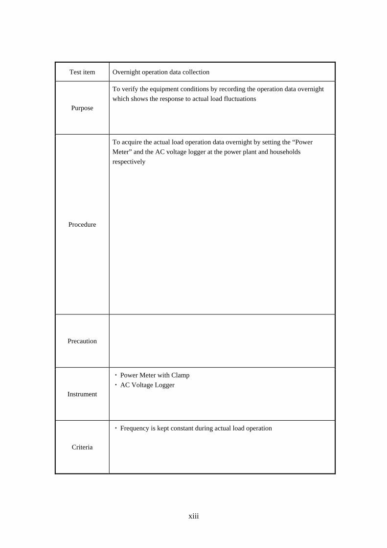
Test item Overnight operation data collection
Purpose
To verify the equipment conditions by recording the operation data overnight
which shows the response to actual load fluctuations
Procedure
To acquire the actual load operation data overnight by setting the “Power
Meter” and the AC voltage logger at the power plant and households
respectively
Precaution
Instrument
・ Power Meter with Clamp
・ AC Voltage Logger
Criteria
・ Frequency is kept constant during actual load operation

Department of Energy
Energy Complex Merritt Road, Fort Bonifacio, Taguig City, Metro Manila
TEL: 479-2900 FAX: 840-1817