Embed Size (px)
DESCRIPTION
GDS-2000A Series User Manual
Citation preview
Digital Storage Oscilloscope
GDS-2000A Series
USER MANUAL GW INSTEK PART NO. 82DS-2304AED1
ISO-9001 CERTIFIED MANUFACTURER
This manual contains proprietary information, which is protected by copyright. All rights are reserved. No part of this manual may be photocopied, reproduced or translated to another language without prior written consent of Good Will company.
The information in this manual was correct at the time of printing. However, Good Will continues to improve products and reserves the rights to change specification, equipment, and maintenance procedures at any time without notice.
Good Will Instrument Co., Ltd. No. 7-1, Jhongsing Rd., Tucheng Dist., New Taipei City 236, Taiwan
TABLE OF CONTENTS
3
Table of Contents SAFETY INSTRUCTIONS ................................................... 5
GETTING STARTED ......................................................... 10
GDS-2000A Series Overview................. 11
Appearance .......................................... 16
Set Up .................................................. 29
QUICK REFERENCE ......................................................... 41
Menu Tree / Operation Shortcuts ........ 43
Default Settings ................................... 61
Built-in Help ........................................ 63
MEASUREMENT .............................................................. 64
Basic Measurement ............................. 65
Automatic Measurement ...................... 72
Cursor Measurement ........................... 85
Math Operation ................................... 93
CONFIGURATION .......................................................... 101
Acquisition ........................................ 103
Segmented Memory Acquisition Overview .......................................................... 111
Display............................................... 124
Horizontal View ................................. 130
Vertical View (Channel) ...................... 137
Trigger ............................................... 144
Search ................................................ 163
System Info / Language / Clock ......... 168
OPTIONAL SOFTWARE and APPS. ................................. 174
Applications ....................................... 175
GDS-2000A Series User Manual
4
Optional Software .............................. 182
SAVE/RECALL ................................................................ 185
File Format/Utility ............................. 186
Create/Edit Labels .............................. 191
Save ................................................... 195
Recall ................................................. 202
Reference Waveforms ......................... 209
FILE UTILITIES ............................................................... 211
HARDCOPY KEY ............................................................. 218
REMOTE CONTROL CONFIG ......................................... 222
Interface Configuration ...................... 223
Web Server ......................................... 238
MAINTENANCE ............................................................. 241
FAQ ............................................................................... 246
APPENDIX ..................................................................... 249
GDS-2000A Specifications .................. 249
Probe Specifications .......................... 254
GDS-2000A Dimensions ..................... 256
Declaration of Conformity .................. 257
INDEX ............................................................................ 258

SAFETY INSTRUCTIONS
5
SAFETY INSTRUCTIONS This chapter contains important safety instructions that you must follow during operation and storage. Read the following before any operation to insure your safety and to keep the instrument in the best possible condition.
Safety Symbols
These safety symbols may appear in this manual or on the GDS-2000A.
WARNING Warning: Identifies conditions or practices that could result in injury or loss of life.
CAUTION Caution: Identifies conditions or practices that could result in damage to the GDS-2000A or to other properties.
DANGER High Voltage
Attention Refer to the Manual
Protective Conductor Terminal
Earth (ground) Terminal

GDS-2000A Series User Manual
6
Do not dispose electronic equipment as unsorted municipal waste. Please use a separate collection facility or contact the supplier from which this instrument was purchased.
Safety Guidelines
General Guideline
CAUTION
Make sure the BNC input voltage does not exceed 300V peak.
Never connect a hazardous live voltage to the ground side of the BNC connectors. It might lead to fire and electric shock.
Do not place any heavy object on the GDS-2000A.
Avoid severe impact or rough handling that leads to damaging the GDS-2000A.
Do not discharge static electricity to the GDS-2000A.
Use only mating connectors, not bare wires, for the terminals.
Do not block the cooling fan opening.
Do not perform measurement at a power source or building installation site (Note below).
Do not disassemble the GDS-2000A unless you are qualified.
(Measurement categories) EN 61010-1:2010 specifies the measurement categories and their requirements as follows. The GDS-2000A falls under category I.
Measurement category IV is for measurement performed at the source of low-voltage installation.
Measurement category III is for measurement performed in the building installation.
Measurement category II is for measurement performed on the circuits directly connected to the low voltage installation.
Measurement category I is for measurements performed on circuits not directly connected to Mains.

SAFETY INSTRUCTIONS
7
Power Supply
WARNING
AC Input voltage: 100 ~ 240V AC, 48 ~ 63Hz, auto selection. Power consumption: 96VA.
Connect the protective grounding conductor of the AC power cord to an earth ground, to avoid electrical shock.
Cleaning the GDS-2000A
Disconnect the power cord before cleaning.
Use a soft cloth dampened in a solution of mild detergent and water. Do not spray any liquid.
Do not use chemicals containing harsh materials such as benzene, toluene, xylene, and acetone.
Operation Environment
Location: Indoor, no direct sunlight, dust free, almost non-conductive pollution (Note below)
Relative Humidity: < 80%
Altitude: < 2000m
Temperature: 0°C to 50°C
(Pollution Degree) EN 61010-1:2001 specifies the pollution degrees and their requirements as follows. The GDS-2000A falls under degree 2.
Pollution refers to “addition of foreign matter, solid, liquid, or gaseous (ionized gases), that may produce a reduction of dielectric strength or surface resistivity”.
Pollution degree 1: No pollution or only dry, non-conductive pollution occurs. The pollution has no influence.
Pollution degree 2: Normally only non-conductive pollution occurs. Occasionally, however, a temporary conductivity caused by condensation must be expected.
Pollution degree 3: Conductive pollution occurs, or dry, non-conductive pollution occurs which becomes conductive due to condensation which is expected. In such conditions, equipment is normally protected against exposure to direct sunlight, precipitation, and full wind pressure, but neither temperature nor humidity is controlled.
Storage environment
Location: Indoor
Temperature: -10°C to 60°C
40°C /93% RH 41°C ~60°C /65% RH

GDS-2000A Series User Manual
8
Disposal
Do not dispose this instrument as unsorted municipal waste. Please use a separate collection facility or contact the supplier from which this instrument was purchased. Please make sure discarded electrical waste is properly recycled to reduce environmental impact.
SAFETY INSTRUCTIONS
9
Power cord for the United Kingdom
When using the oscilloscope in the United Kingdom, make sure the power cord meets the following safety instructions.
NOTE: This lead/appliance must only be wired by competent persons
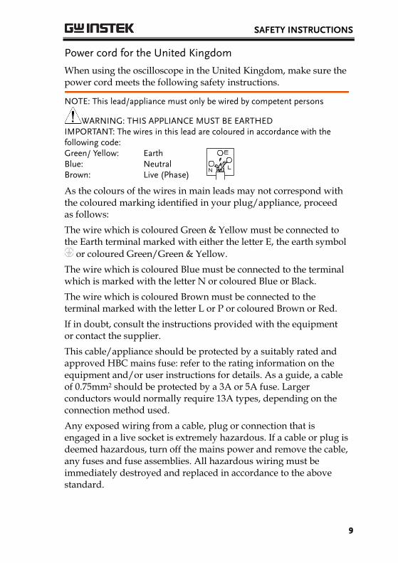
WARNING: THIS APPLIANCE MUST BE EARTHED IMPORTANT: The wires in this lead are coloured in accordance with the following code: Green/ Yellow: Earth
Blue: Neutral Brown: Live (Phase)
As the colours of the wires in main leads may not correspond with the coloured marking identified in your plug/appliance, proceed as follows:
The wire which is coloured Green & Yellow must be connected to the Earth terminal marked with either the letter E, the earth symbol
or coloured Green/Green & Yellow.
The wire which is coloured Blue must be connected to the terminal which is marked with the letter N or coloured Blue or Black.
The wire which is coloured Brown must be connected to the terminal marked with the letter L or P or coloured Brown or Red.
If in doubt, consult the instructions provided with the equipment or contact the supplier.
This cable/appliance should be protected by a suitably rated and approved HBC mains fuse: refer to the rating information on the equipment and/or user instructions for details. As a guide, a cable of 0.75mm2 should be protected by a 3A or 5A fuse. Larger conductors would normally require 13A types, depending on the connection method used.
Any exposed wiring from a cable, plug or connection that is engaged in a live socket is extremely hazardous. If a cable or plug is deemed hazardous, turn off the mains power and remove the cable, any fuses and fuse assemblies. All hazardous wiring must be immediately destroyed and replaced in accordance to the above standard.
GDS-2000A Series User Manual
10
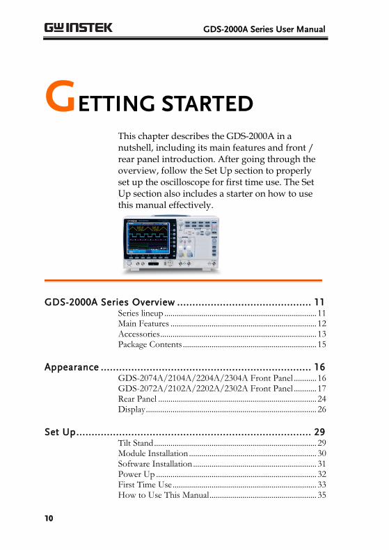
GETTING STARTED This chapter describes the GDS-2000A in a nutshell, including its main features and front / rear panel introduction. After going through the overview, follow the Set Up section to properly set up the oscilloscope for first time use. The Set Up section also includes a starter on how to use this manual effectively.
GDS-2000A Series Overview ............................................ 11 Series lineup .......................................................................... 11 Main Features ....................................................................... 12 Accessories ............................................................................ 13 Package Contents ................................................................. 15
Appearance ..................................................................... 16 GDS-2074A/2104A/2204A/2304A Front Panel ........... 16 GDS-2072A/2102A/2202A/2302A Front Panel ........... 17 Rear Panel ............................................................................. 24 Display ................................................................................... 26
Set Up ............................................................................. 29 Tilt Stand ............................................................................... 29 Module Installation .............................................................. 30 Software Installation ............................................................ 31 Power Up .............................................................................. 32 First Time Use ...................................................................... 33 How to Use This Manual .................................................... 35
GETTING STARTED
11
GDS-2000A Series Overview
Series lineup
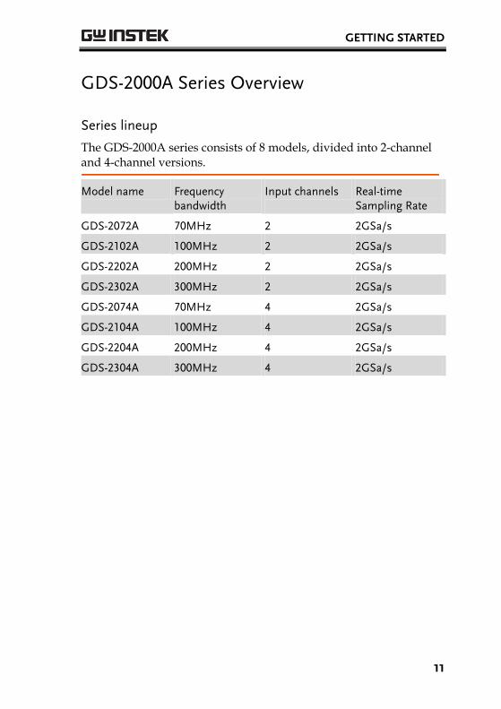
The GDS-2000A series consists of 8 models, divided into 2-channel and 4-channel versions.
Model name Frequency bandwidth
Input channels Real-time Sampling Rate
GDS-2072A 70MHz 2 2GSa/s
GDS-2102A 100MHz 2 2GSa/s
GDS-2202A 200MHz 2 2GSa/s
GDS-2302A 300MHz 2 2GSa/s
GDS-2074A 70MHz 4 2GSa/s
GDS-2104A 100MHz 4 2GSa/s
GDS-2204A 200MHz 4 2GSa/s
GDS-2304A 300MHz 4 2GSa/s
GDS-2000A Series User Manual
12
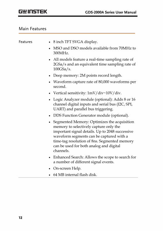
Main Features
Features 8 inch TFT SVGA display.
MSO and DSO models available from 70MHz to 300MHz.
All models feature a real-time sampling rate of 2GSa/s and an equivalent time sampling rate of 100GSa/s.
Deep memory: 2M points record length.
Waveform capture rate of 80,000 waveforms per second.
Vertical sensitivity: 1mV/div~10V/div.
Logic Analyzer module (optional): Adds 8 or 16 channel digital inputs and serial bus (I2C, SPI, UART) and parallel bus triggering.
DDS Function Generator module (optional).
Segmented Memory: Optimizes the acquisition memory to selectively capture only the important signal details. Up to 2048 successive waveform segments can be captured with a time-tag resolution of 8ns. Segmented memory can be used for both analog and digital channels.
Enhanced Search: Allows the scope to search for a number of different signal events.
On-screen Help.
64 MB internal flash disk.
GETTING STARTED
13
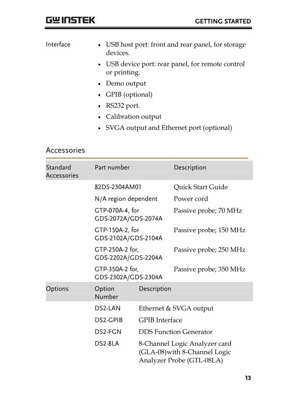
Interface USB host port: front and rear panel, for storage devices.
USB device port: rear panel, for remote control or printing.
Demo output
GPIB (optional)
RS232 port.
Calibration output
SVGA output and Ethernet port (optional)
Accessories
Standard Accessories
Part number Description
82DS-2304AM01 Quick Start Guide
N/A region dependent Power cord
GTP-070A-4, for GDS-2072A/GDS-2074A
Passive probe; 70 MHz
GTP-150A-2, for GDS-2102A/GDS-2104A
Passive probe; 150 MHz
GTP-250A-2 for, GDS-2202A/GDS-2204A
Passive probe; 250 MHz
GTP-350A-2 for, GDS-2302A/GDS-2304A
Passive probe; 350 MHz
Options Option Number
Description
DS2-LAN Ethernet & SVGA output
DS2-GPIB GPIB Interface
DS2-FGN DDS Function Generator
DS2-8LA 8-Channel Logic Analyzer card (GLA-08)with 8-Channel Logic Analyzer Probe (GTL-08LA)

GDS-2000A Series User Manual
14
DS2-16LA 16-Channel Logic Analyzer card (GLA-16)with 16-Channel Logic Analyzer Probe (GTL-16A)
Optional Accessories
Part number Description
GTC-001 Instrument cart, 470(W)x430(D)mm (U.S. type input socket)
GTC-002 Instrument cart, 330(W)x430(D)mm (U.S. type input socket)
GTL-110 test lead, BNC to BNC heads
GTL-232 RS-232C cable, 9-pin Female to 9-pin female, Null modem for computer
GTL-242 USB cable, USB2.0A-B type cable 4P
GTL-08LA 8-Channel Logic Analyzer Testing Probe
GTL-16LA 16-Channel Logic Analyzer Testing Probe
GLA-08 8-Channel Logic Analyzer Card
GLA-16 16-Channel Logic Analyzer Card
GTP-070A-4 Passive probe; 70 MHz
GTP-150A-2 Passive probe; 150 MHz
GTP-250A-2 Passive probe; 250 MHz
GTP-350A-2 Passive probe; 350 MHz
Drivers
USB driver LabVIEW driver
GETTING STARTED
15
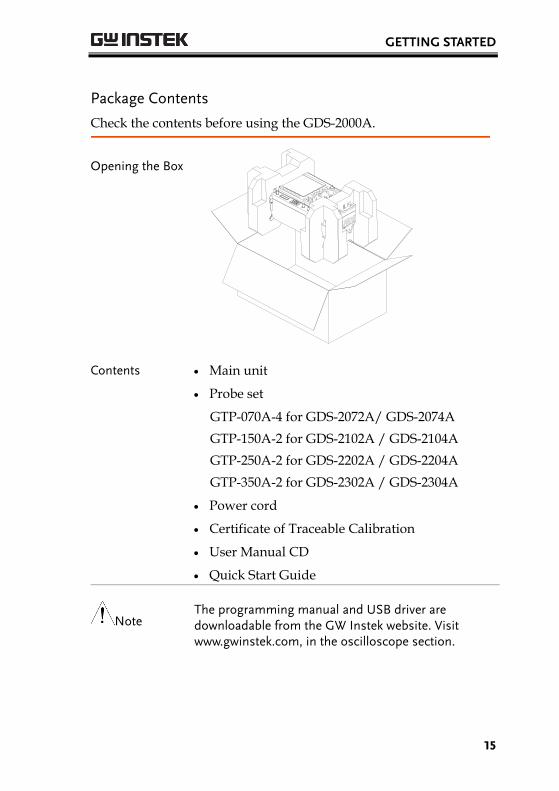
Package Contents
Check the contents before using the GDS-2000A.
Opening the Box
Contents Main unit
Probe set
GTP-070A-4 for GDS-2072A/ GDS-2074A
GTP-150A-2 for GDS-2102A / GDS-2104A
GTP-250A-2 for GDS-2202A / GDS-2204A
GTP-350A-2 for GDS-2302A / GDS-2304A
Power cord
Certificate of Traceable Calibration
User Manual CD
Quick Start Guide
Note The programming manual and USB driver are downloadable from the GW Instek website. Visit www.gwinstek.com, in the oscilloscope section.
GDS-2000A Series User Manual
16
Appearance
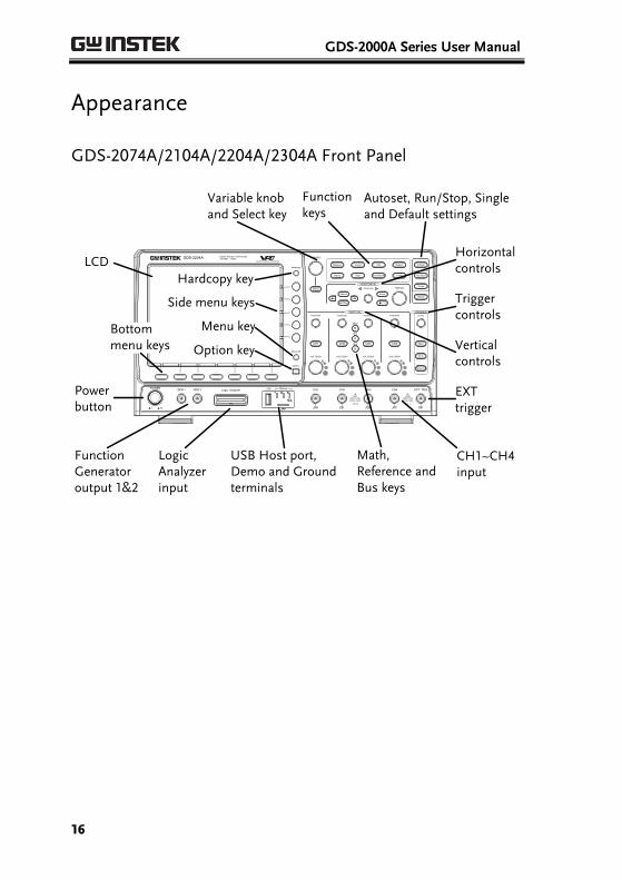
GDS-2074A/2104A/2204A/2304A Front Panel
POWER
CH1 CH2
POSITION TIME/DIV
POSITIONPOSITION
VOLTS/DIV VOLTS/DIV
Autoset
Menu
50 %
Force-Trig
Select
TRIGGER
HORIZONTAL
VARIABLE
Measure Cursor
Display Help Save/Recall Utility
Acquire
Single
Run/Stop
Search
Set/Clear
CH3 CH4
POSITION POSITION
VOLTS/DIV VOLTS/DIV
VERTICAL
M
R
B
Test
CH1 CH2 CH3 CH4 EXT TRIG
CAT
MW 16pF
300Vpk MAX.
1
CAT
MW 16pF
300Vpk MAX.
Hardcopy
Option
Menu Off
LEVEL
Zoom
MATH
REF
DemoLogic Analyzer
1
BUS
Digital Storage OscilloscopeGDS-2204A 200 MHz 2 GS/sVisual Persistence Oscilloscope
GEN 1 GEN 2
Default
LCD
Variable knob and Select key
Autoset, Run/Stop, Single and Default settings
CH1~CH4 input
Trigger controls
Function keys
USB Host port, Demo and Ground terminals
Function Generator output 1&2
Power button
Hardcopy key
Option key
Math, Reference and Bus keys
Bottom menu keys
Horizontal controls
Menu key
Vertical controls
Logic Analyzer input
EXT trigger
Side menu keys
GETTING STARTED
17
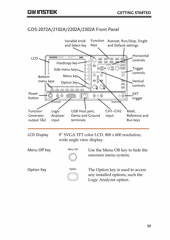
GDS-2072A/2102A/2202A/2302A Front Panel
CH1 CH2
POSITION TIME/DIV
POSITIONPOSITION
VOLTS/DIV VOLTS/DIV
Autoset
Menu
50 %
Force-Trig
Select
TRIGGER
HORIZONTAL
VARIABLE
Measure Cursor
Display Help Save/Recall Utility
Acquire
Single
Run/Stop
LEVEL
Search
Set/Clear
VERTICAL
Test
POWER 2V
Hardcopy
Option
Menu Off
Zoom
CAT
M 16pF
300Vpk MAX.
1
CAT
MW 16pF
300Vpk MAX.
1
M
R
B
MATH
REF
BUS
Default
Logic AnalyzerGEN 1 GEN 2 CH1 CH2 EXT TRIG
Digital Storage OscilloscopeGDS-2202A 200 MHz 2 GS/sVisual Persistence Oscilloscope
W
LCD
Variable knob and Select key
Autoset, Run/Stop, Single and Default settings
Math, Reference and Bus keys
Trigger controls
Function keys
USB Host port, Demo and Ground terminals
Function Generator output 1&2
Power button
Hardcopy key
Option key
CH1~CH2 input
Bottom menu keys
Horizontal controls
Menu key
Vertical controls
Logic Analyzer input
EXT trigger
Side menu keys
LCD Display 8” SVGA TFT color LCD. 800 x 600 resolution, wide angle view display.
Menu Off Key Menu Off
Use the Menu Off key to hide the onscreen menu system.
Option Key Option
The Option key is used to access any installed options, such the Logic Analyzer option.

GDS-2000A Series User Manual
18
Menu Keys The Side menu and Bottom menu keys are used to make selections from the soft-menus on the LCD user interface.
To choose menu items, use the 7 Bottom menu keys located on the bottom of the display panel.
To select a variable or option from a menu, use the Side menu keys on the side of the panel. See page 35 for details.
Hardcopy
Option
Menu Off
Side menu keys
Bottom menu keys
Hardcopy Key Hardcopy
The Hardcopy key is a quick-save or quick-print key, depending on its configuration. For more information see pages 220(save) or 219(print).
Variable Knob and Select Key
Select
VARIABLE
The Variable knob is used to increase/decrease values or to move between parameters.
The Select key is used to make selections.
Function Keys The Function keys are used to enter and configure different functions on the GDS-2000A.
GETTING STARTED
19
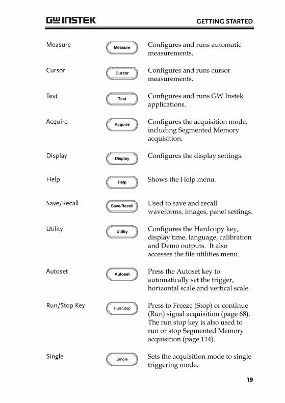
Measure Measure
Configures and runs automatic measurements.
Cursor Cursor
Configures and runs cursor measurements.
Test Test
Configures and runs GW Instek applications.
Acquire Acquire
Configures the acquisition mode, including Segmented Memory acquisition.
Display Display
Configures the display settings.
Help Help
Shows the Help menu.
Save/Recall Save/Recall
Used to save and recall waveforms, images, panel settings.
Utility Utility
Configures the Hardcopy key, display time, language, calibration and Demo outputs. It also accesses the file utilities menu.
Autoset Autoset
Press the Autoset key to automatically set the trigger, horizontal scale and vertical scale.
Run/Stop Key Run/Stop
Press to Freeze (Stop) or continue (Run) signal acquisition (page 68). The run stop key is also used to run or stop Segmented Memory acquisition (page 114).
Single Single
Sets the acquisition mode to single triggering mode.
GDS-2000A Series User Manual
20
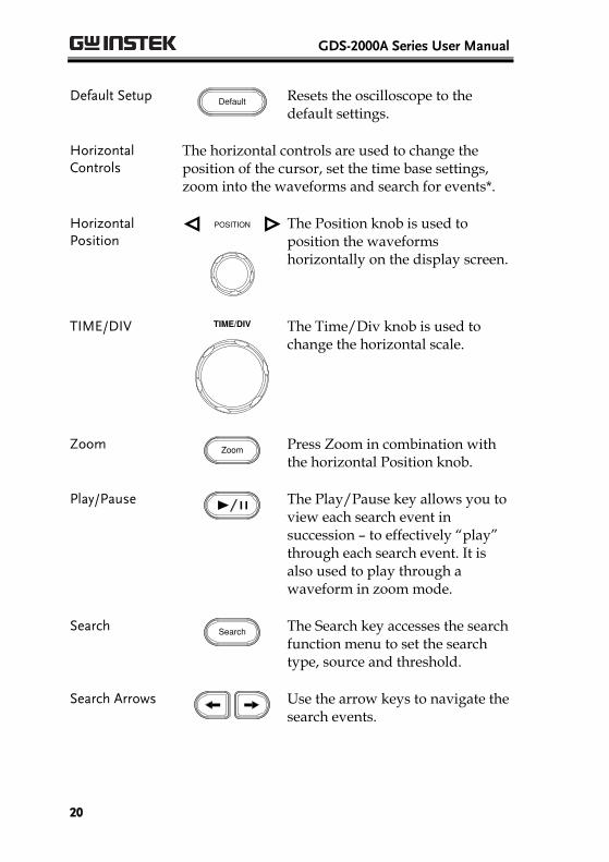
Default Setup Default
Resets the oscilloscope to the default settings.
Horizontal Controls
The horizontal controls are used to change the position of the cursor, set the time base settings, zoom into the waveforms and search for events*.
Horizontal Position
POSITION
The Position knob is used to position the waveforms horizontally on the display screen.
TIME/DIV TIME/DIV
The Time/Div knob is used to change the horizontal scale.
Zoom Zoom
Press Zoom in combination with the horizontal Position knob.
Play/Pause
The Play/Pause key allows you to view each search event in succession – to effectively “play” through each search event. It is also used to play through a waveform in zoom mode.
Search Search
The Search key accesses the search function menu to set the search type, source and threshold.
Search Arrows
Use the arrow keys to navigate the search events.
GETTING STARTED
21
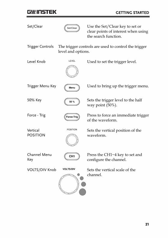
Set/Clear Set/Clear
Use the Set/Clear key to set or clear points of interest when using the search function.
Trigger Controls The trigger controls are used to control the trigger level and options.
Level Knob LEVEL
Used to set the trigger level.
Trigger Menu Key Menu
Used to bring up the trigger menu.
50% Key 50 %
Sets the trigger level to the half way point (50%).
Force - Trig Force-Trig
Press to force an immediate trigger of the waveform.
Vertical POSITION
POSITION
Sets the vertical position of the waveform.
Channel Menu Key
CH1
Press the CH1~4 key to set and configure the channel.
VOLTS/DIV Knob VOLTS/DIV
Sets the vertical scale of the channel.
GDS-2000A Series User Manual
22
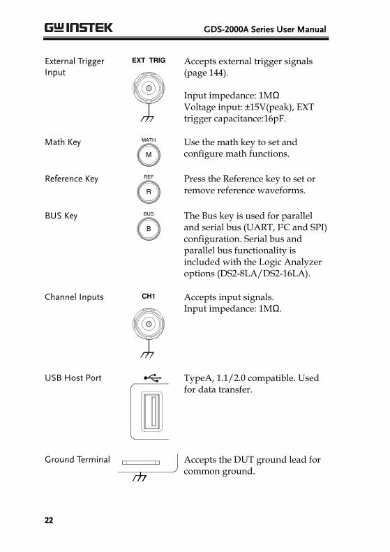
External Trigger Input
EXT TRIG
Accepts external trigger signals (page 144).
Input impedance: 1MΩ Voltage input: ±15V(peak), EXT trigger capacitance:16pF.
Math Key
M
MATH
Use the math key to set and configure math functions.
Reference Key
R
REF
Press the Reference key to set or remove reference waveforms.
BUS Key
B
BUS
The Bus key is used for parallel and serial bus (UART, I2C and SPI) configuration. Serial bus and parallel bus functionality is included with the Logic Analyzer options (DS2-8LA/DS2-16LA).
Channel Inputs CH1
Accepts input signals. Input impedance: 1MΩ.
USB Host Port Demo
TypeA, 1.1/2.0 compatible. Used for data transfer.
Ground Terminal
Demo
Accepts the DUT ground lead for common ground.
GETTING STARTED
23
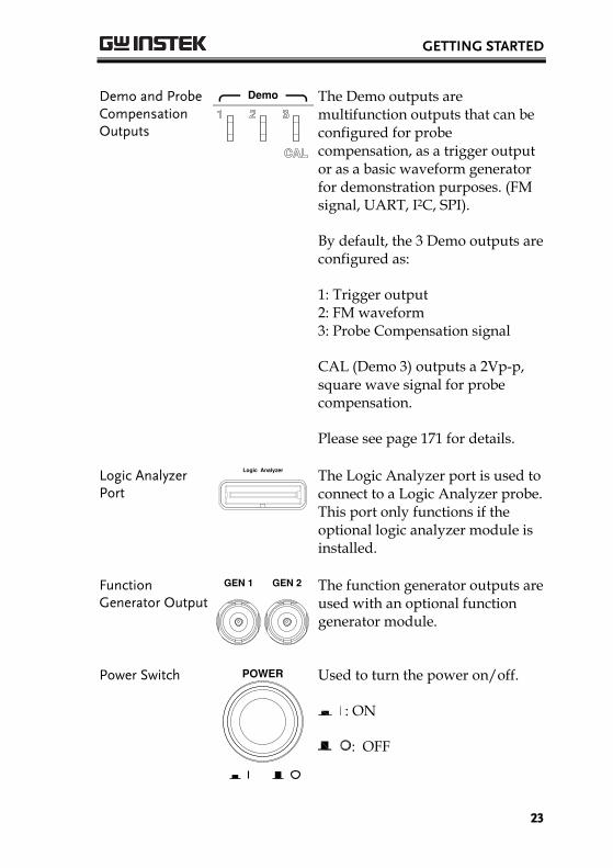
Demo and Probe Compensation Outputs
Demo
The Demo outputs are multifunction outputs that can be configured for probe compensation, as a trigger output or as a basic waveform generator for demonstration purposes. (FM signal, UART, I2C, SPI).
By default, the 3 Demo outputs are configured as:
1: Trigger output 2: FM waveform 3: Probe Compensation signal
CAL (Demo 3) outputs a 2Vp-p, square wave signal for probe compensation.
Please see page 171 for details.
Logic Analyzer Port
Logic Analyzer
The Logic Analyzer port is used to connect to a Logic Analyzer probe. This port only functions if the optional logic analyzer module is installed.
Function Generator Output
GEN 1 GEN 2
The function generator outputs are used with an optional function generator module.
Power Switch POWER
Used to turn the power on/off.
: ON
: OFF
GDS-2000A Series User Manual
24
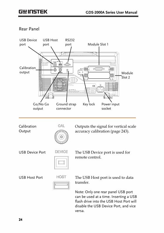
Rear Panel
LINE VOLTAGEAC 100 240V
RANGE
FREQUENCY 50 60Hz
POWER MAX. 55W 80VA
CAUTION
TO AVOID ELECTRIC SHOCK THE POWER CORD PROTECTIVE GROUNDING
DO NOT REMOVE COVERS. REFER SERVICING TO QUALIFIED PERSONNEL.
CONDUCTOR MUST BE CONNECTED TO GROUND.
Ser. No. Label
Calibration output
RS232 port Module Slot 1
Module Slot 2
Key lock Power input socket
Ground strap connector
Go/No Go output
USB Host port
USB Device port
Calibration Output
Outputs the signal for vertical scale accuracy calibration (page 243).
USB Device Port
The USB Device port is used for remote control.
USB Host Port
The USB Host port is used to data transfer.
Note: Only one rear panel USB port can be used at a time. Inserting a USB flash drive into the USB Host Port will disable the USB Device Port, and vice versa.
GETTING STARTED
25
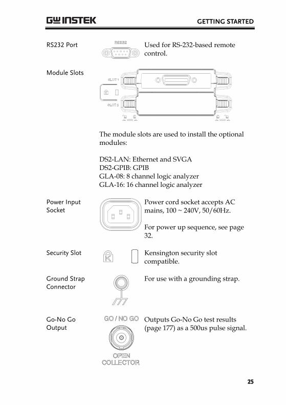
RS232 Port
Used for RS-232-based remote control.
Module Slots
The module slots are used to install the optional modules:
DS2-LAN: Ethernet and SVGA DS2-GPIB: GPIB GLA-08: 8 channel logic analyzer GLA-16: 16 channel logic analyzer
Power Input Socket
Power cord socket accepts AC mains, 100 ~ 240V, 50/60Hz.
For power up sequence, see page 32.
Security Slot
Kensington security slot compatible.
Ground Strap Connector
For use with a grounding strap.
Go-No Go Output
Outputs Go-No Go test results (page 177) as a 500us pulse signal.
GDS-2000A Series User Manual
26
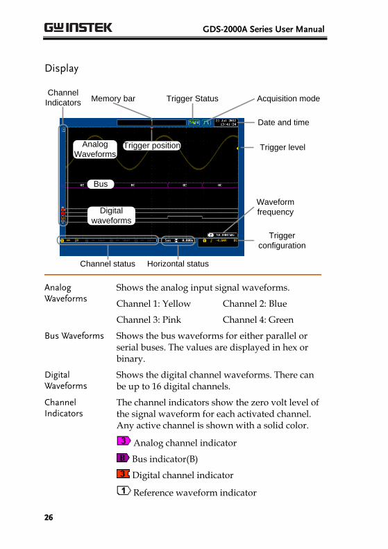
Display
Memory bar
Digital
waveforms
Analog
Waveforms
Bus
Channel status Horizontal status
Trigger
configuration
Waveform
frequency
Date and time
Trigger position
Acquisition modeTrigger Status
Trigger level
Channel
Indicators
Analog Waveforms
Shows the analog input signal waveforms.
Channel 1: Yellow Channel 2: Blue
Channel 3: Pink Channel 4: Green
Bus Waveforms Shows the bus waveforms for either parallel or serial buses. The values are displayed in hex or binary.
Digital Waveforms
Shows the digital channel waveforms. There can be up to 16 digital channels.
Channel Indicators
The channel indicators show the zero volt level of the signal waveform for each activated channel. Any active channel is shown with a solid color.
Analog channel indicator
Bus indicator(B)
Digital channel indicator
Reference waveform indicator
GETTING STARTED
27
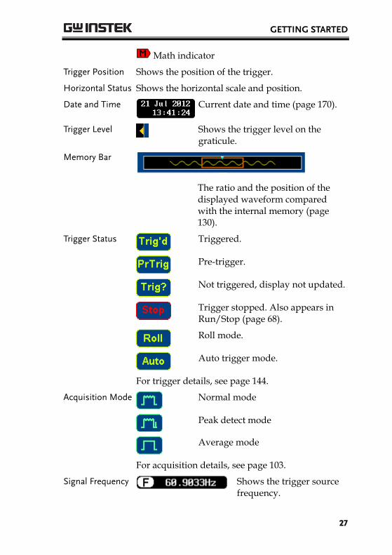
Math indicator
Trigger Position Shows the position of the trigger.
Horizontal Status Shows the horizontal scale and position.
Date and Time Current date and time (page 170).
Trigger Level
Shows the trigger level on the graticule.
Memory Bar
The ratio and the position of the displayed waveform compared with the internal memory (page 130).
Trigger Status
Triggered.
Pre-trigger.
Not triggered, display not updated.
Trigger stopped. Also appears in Run/Stop (page 68).
Roll mode.
Auto trigger mode.
For trigger details, see page 144.
Acquisition Mode
Normal mode
Peak detect mode
Average mode
For acquisition details, see page 103.
Signal Frequency
Shows the trigger source frequency.
GDS-2000A Series User Manual
28
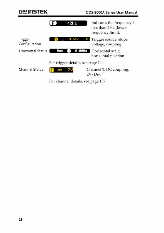
Indicates the frequency is less than 2Hz (lower frequency limit).
Trigger Configuration
Trigger source, slope, voltage, coupling.
Horizontal Status Horizontal scale, horizontal position.
For trigger details, see page 144.
Channel Status
Channel 1, DC coupling, 2V/Div.
For channel details, see page 137.
GETTING STARTED
29
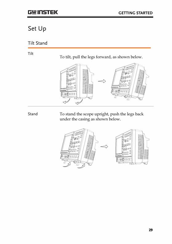
Set Up
Tilt Stand
Tilt To tilt, pull the legs forward, as shown below.
Stand To stand the scope upright, push the legs back under the casing as shown below.
GDS-2000A Series User Manual
30
Module Installation
Background The GDS-2000A has a number of optional modules that can be installed into the module slots on the rear panel. These modules must be installed before power up.
Note The modules are not hot-swappable. Please ensure the power is off before connecting or disconnecting any of the modules from the rear panel.
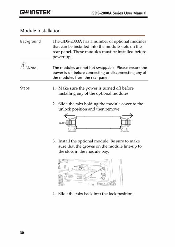
Steps 1. Make sure the power is turned off before installing any of the optional modules.
2. Slide the tabs holding the module cover to the unlock position and then remove
3. Install the optional module. Be sure to make sure that the groves on the module line-up to the slots in the module bay.
4. Slide the tabs back into the lock position.
GETTING STARTED
31
Software Installation
Background The GDS-2000A has optional software packages to expand the functionality of the standard GDS-2000A.An activation key is required to activate any optional software. A different activation key is required for each optional software package.
For the latest files and information regarding the optional software packages, see the GW Instek website: www.gwinstek.com or contact your nearest distributor.
Steps 1. Install any hardware modules if needed. See page 30 for installation details.
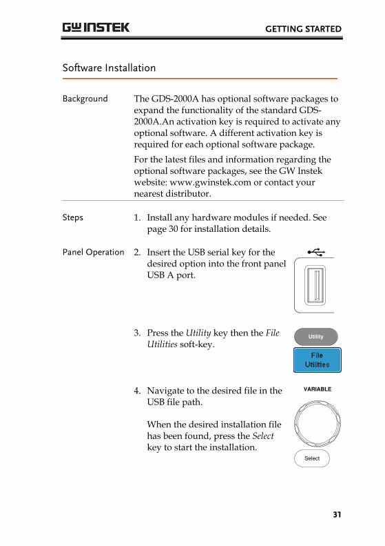
Panel Operation 2. Insert the USB serial key for the desired option into the front panel USB A port.
Demo
3. Press the Utility key then the File Utilities soft-key.
Utility
4. Navigate to the desired file in the USB file path.
When the desired installation file has been found, press the Select key to start the installation.
VARIABLE
Select
GDS-2000A Series User Manual
32
5. The installation will complete in a few seconds. When finished a pop-up message will appear asking you to restart the GDS-2000A.
6. Restart the GDS-2000A.
Power Up
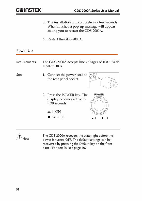
Requirements The GDS-2000A accepts line voltages of 100 ~ 240V at 50 or 60Hz.
Step 1. Connect the power cord to the rear panel socket.
2. Press the POWER key. The
display becomes active in ~ 30 seconds.
: ON
: OFF
POWER
Note The GDS-2000A recovers the state right before the power is turned OFF. The default settings can be recovered by pressing the Default key on the front panel. For details, see page 202.
GETTING STARTED
33
First Time Use
Background This section describes how to connect a signal, adjust the scale, and compensate the probe. Before operating the GDS-2000A in a new environment, run these steps to make sure the instrument performs at its full potential.
1. Power On Follow the procedures on the previous page.
2. Set the Date and Time
Set the date and time. Page 170
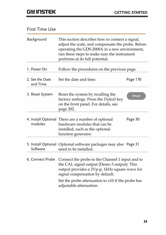
3. Reset System Reset the system by recalling the factory settings. Press the Default key on the front panel. For details, see page 202.
Default
4. Install Optional modules
There are a number of optional hardware modules that can be installed, such as the optional function generator.
Page 30
5. Install Optional Software
Optional software packages may also need to be installed.
Page 31
6. Connect Probe Connect the probe to the Channel 1 input and to the CAL signal output (Demo 3 output). This output provides a 2Vp-p, 1kHz square wave for signal compensation by default.
Set the probe attenuation to x10 if the probe has adjustable attenuation.

GDS-2000A Series User Manual
34
POSITION
CH1Demo
x1
x10X10
X1 CH1
Demo
6. Capture Signal (Autoset)
Press the Autoset key. A square waveform appears on the center of the screen. For Autoset details, see page 66.
Autoset
7. Select Vector Waveform
Press the Display key, and set the display to Vector on the bottom menu.
Display
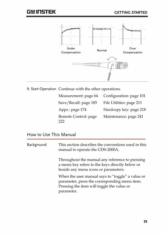
8. Compensate Probe
Turn the adjustment point on the probe to make the square waveform edge flat.
GETTING STARTED
35
Under Compensation
NormalOver
Compensation
9. Start Operation Continue with the other operations.
Measurement: page 64 Configuration: page 101
Save/Recall: page 185 File Utilities: page 211
Apps.: page 174 Hardcopy key: page 218
Remote Control: page 222
Maintenance: page 241
How to Use This Manual
Background This section describes the conventions used in this manual to operate the GDS-2000A.
Throughout the manual any reference to pressing a menu key refers to the keys directly below or beside any menu icons or parameters.
When the user manual says to “toggle” a value or parameter, press the corresponding menu item. Pressing the item will toggle the value or parameter.

GDS-2000A Series User Manual
36
Active parameters are highlighted for each menu item. For example in the example below, Coupling is currently set to DC.
If a menu item can be toggled from one value or parameter to another, the available options will be visible, with the current option highlighted. In the example below the slope can be toggled from a rising slope to a falling slope or either slop.
Menu item
Parameter
Menu item
Active
parameter
Optional
parameters
Menu item
Selecting a Menu Item, Parameter or Variable
When the user manual says to “select” a value from one of the side menu parameters, first press the corresponding menu key and use the Variable knob to either scroll through a parameter list or to increase or decrease a variable.
Example 1
1
23
1. Press a bottom menu key to access the side menu.
GETTING STARTED
37
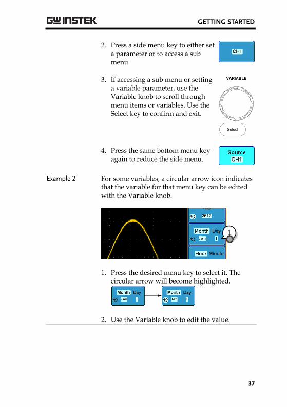
2. Press a side menu key to either set
a parameter or to access a sub menu.
3. If accessing a sub menu or setting
a variable parameter, use the Variable knob to scroll through menu items or variables. Use the Select key to confirm and exit.
VARIABLE
Select
4. Press the same bottom menu key
again to reduce the side menu.
Example 2 For some variables, a circular arrow icon indicates that the variable for that menu key can be edited with the Variable knob.
1
1. Press the desired menu key to select it. The
circular arrow will become highlighted.
2. Use the Variable knob to edit the value.
GDS-2000A Series User Manual
38
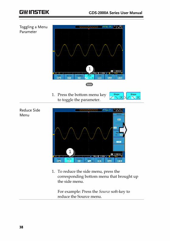
Toggling a Menu Parameter
1
1. Press the bottom menu key
to toggle the parameter.
Reduce Side Menu
1
1. To reduce the side menu, press the
corresponding bottom menu that brought up the side menu. For example: Press the Source soft-key to reduce the Source menu.
GETTING STARTED
39
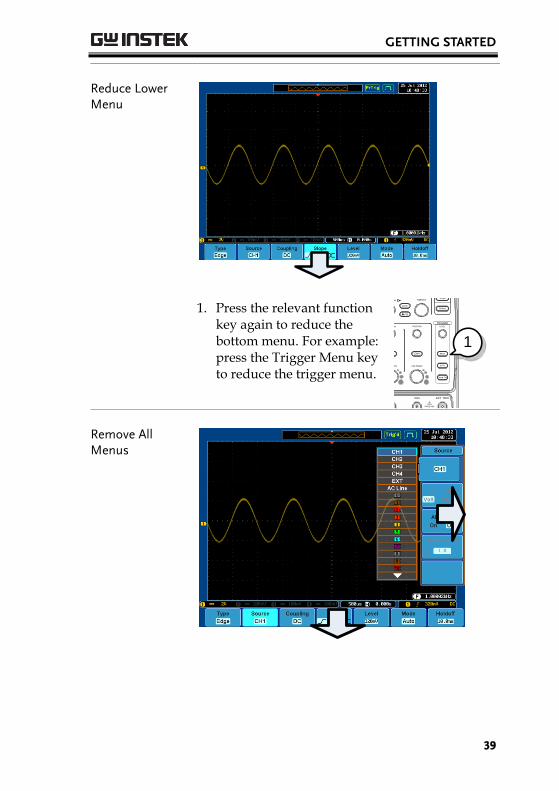
Reduce Lower Menu
1. Press the relevant function
key again to reduce the bottom menu. For example: press the Trigger Menu key to reduce the trigger menu.
POWER
CH1 CH2
POSITION TIME/DIV
POSITIONPOSITION
VOLTS/DIV VOLTS/DIV
Autoset
Menu
50 %
Force-Trig
Select
TRIGGER
HORIZONTAL
VARIABLE
Measure Cursor
Display Help Save/Recall Utility
Acquire
Single
Run/Stop
Search
Set/Clear
CH3 CH4
POSITION POSITION
VOLTS/DIV VOLTS/DIV
VERTICAL
M
R
B
Test
CH1 CH2 CH3 CH4 EXT TRIG
CAT
MW 16pF
300Vpk MAX.
1
CAT
MW 16pF
300Vpk MAX.
Hardcopy
Option
Menu Off
LEVEL
Zoom
MATH
REF
DemoLogic Analyzer
1
BUS
Digital Storage OscilloscopeGDS-2204A 200 MHz 2 GS/sVisual Persistence Oscilloscope
GEN 1 GEN 2
Default
1
Remove All Menus
GDS-2000A Series User Manual
40
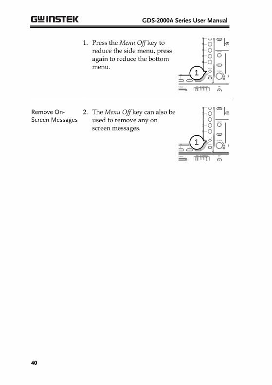
1. Press the Menu Off key to
reduce the side menu, press again to reduce the bottom menu.
POWER
CH1 CH2
POSITION TIME/DIV
POSITIONPOSITION
VOLTS/DIV VOLTS/DIV
Autoset
Menu
50 %
Force-Trig
Select
TRIGGER
HORIZONTAL
VARIABLE
Measure Cursor
Display Help Save/Recall Utility
Acquire
Single
Run/Stop
Search
Set/Clear
CH3 CH4
POSITION POSITION
VOLTS/DIV VOLTS/DIV
VERTICAL
M
R
B
Test
CH1 CH2 CH3 CH4 EXT TRIG
CAT
MW 16pF
300Vpk MAX.
1
CAT
MW 16pF
300Vpk MAX.
Hardcopy
Option
Menu Off
LEVEL
Zoom
MATH
REF
DemoLogic Analyzer
1
BUS
Digital Storage OscilloscopeGDS-2204A 200 MHz 2 GS/sVisual Persistence Oscilloscope
GEN 1 GEN 2
Default
1
Remove On-Screen Messages
2. The Menu Off key can also be used to remove any on screen messages.
POWER
CH1 CH2
POSITION TIME/DIV
POSITIONPOSITION
VOLTS/DIV VOLTS/DIV
Autoset
Menu
50 %
Force-Trig
Select
TRIGGER
HORIZONTAL
VARIABLE
Measure Cursor
Display Help Save/Recall Utility
Acquire
Single
Run/Stop
Search
Set/Clear
CH3 CH4
POSITION POSITION
VOLTS/DIV VOLTS/DIV
VERTICAL
M
R
B
Test
CH1 CH2 CH3 CH4 EXT TRIG
CAT
MW 16pF
300Vpk MAX.
1
CAT
MW 16pF
300Vpk MAX.
Hardcopy
Option
Menu Off
LEVEL
Zoom
MATH
REF
DemoLogic Analyzer
1
BUS
Digital Storage OscilloscopeGDS-2204A 200 MHz 2 GS/sVisual Persistence Oscilloscope
GEN 1 GEN 2
Default
1

QUICK REFERENCE
41
QUICK REFERENCE This chapter describes the GDS-2000A menu tree, shortcuts to major operations, built-in Help access, and default factory settings. Use them as a handy reference to get a quick access to the functionality.
Menu Tree / Operation Shortcuts .................................... 43 Convention ........................................................................... 43 Acquire Key .......................................................................... 44 Acquire Key - Segments ...................................................... 44 Autoset Key .......................................................................... 45 CH1 ~ 4 Key ........................................................................ 45 Cursor Key ............................................................................ 46 Display Key ........................................................................... 46 Help Key ............................................................................... 46 Math Key ............................................................................... 47 Measure Key ......................................................................... 48 Hardcopy Key ....................................................................... 49 Run/Stop Key ...................................................................... 49 REF Key ................................................................................ 49 Save/Recall Key ................................................................... 50 Test Key ................................................................................ 51 Test Key – Go-NoGo ......................................................... 51 Trigger Type Menu .............................................................. 52 Trigger Edge Menu .............................................................. 52 Trigger Delay Menu ............................................................. 53 Trigger Pulse Width Menu .................................................. 53 Trigger Video Menu ............................................................ 53 Trigger Pulse Runt Menu .................................................... 54 Trigger Rise & Fall Menu .................................................... 54 Trigger Timeout Menu ........................................................ 54 Utility Key ............................................................................. 55 Utility Key – I/O ................................................................. 56 Utility Key – File Utilities .................................................... 56
GDS-2000A Series User Manual
42
Utility Key – Wave Generator - Demo Outputs ............. 57 Search - Edge ........................................................................ 57 Search – Pulse Width ........................................................... 58 Search - Runt ........................................................................ 58 Search – Rise/Fall Time ...................................................... 59 Zoom Key ............................................................................. 59 Option Key ........................................................................... 60
Default Settings .............................................................. 61
Built-in Help ................................................................... 63
QUICK REFERENCE
43
Menu Tree / Operation Shortcuts
Convention
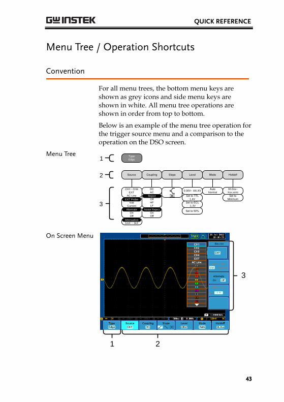
For all menu trees, the bottom menu keys are shown as grey icons and side menu keys are shown in white. All menu tree operations are shown in order from top to bottom.
Below is an example of the menu tree operation for the trigger source menu and a comparison to the operation on the DSO screen.
Menu Tree TypeEdge
Source Coupling Slope Level Mode Holdoff
CH1~ CH4EXT
AC Line
EXT Probe
Volt
Current
DCAC
0.00V~ XX.XV
Set to TTL1.4V
Set to ECL-1.3V
Set to 50%
AutoNormal
00.0ns~Xxx.xxns
Set toMinimumEXT Probe
On
Off
Alternate
1
2
3
1mX ~ 1kXAttenuation
Off
HF
LF
Reject
On
Off
Noise Reject
On Screen Menu
1 2
3
GDS-2000A Series User Manual
44
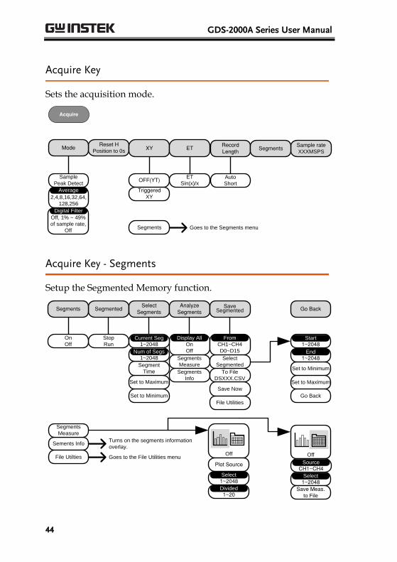
Acquire Key
Sets the acquisition mode.
Segments Goes to the Segments menu
Reset H Position to 0s
XY ET Sample rateXXXMSPS
OFF(YT)
TriggeredXY
ET
Sin(x)/x
Mode
Sample
Peak Detect
2,4,8,16,32,64,
128,256
Average
Off, 1% ~ 49%
of sample rate,
Off
Digital Filter
RecordLength
Auto
Short
Acquire
Segments
Acquire Key - Segments
Setup the Segmented Memory function.
SegmentedSelect
SegmentsAnalyze
SegmentsSave
SegmentedSegments
Stop
Run On
Off
Display All
1~2048Current Seg
Segment
Time
Go Back
On
Off
1~2048Num of Segs
Set to Maximum
Set to Minimum
Segments
Measure
Segments
Info
CH1~CH4
D0~D15
From
Select
Segmented
To File
DSXXX.CSV
Save Now
File Utilities
Sements InfoTurns on the segments information
overlay.
Segments
Measure
File Utilties Goes to the File Utilities menu
1~2048Start
1~2048End
Set to Minimum
Set to Maximum
Go Back
Off
Plot Source
1~2048Select
1~20Divided
Off
1~2048Select
Save Meas. to File
CH1~CH4Source
QUICK REFERENCE
45
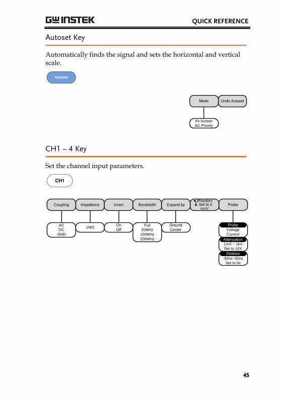
Autoset Key
Automatically finds the signal and sets the horizontal and vertical scale.
Undo AutosetMode
Fit Screen
AC Priority
Autoset
CH1 ~ 4 Key
Set the channel input parameters.
Voltage
Current
Probe
Impedence Invert Bandwidth Expand by Position/ Set to 0
xxxVProbe
OnOff
Coupling
AC
DC
GND
Full20MHz
100MHz
200MHz
1MΩ
1mX ~ 1kX
Set to 10X
Attenuation
-50ns~50ns
Set to 0s
Deskew
GroundCenter
CH1

GDS-2000A Series User Manual
46
Cursor Key
Set cursor positions.
V CursorH Cursor H UnitSet Cursor
Positions As 100%
Set Cursor Positions As
100%
SHz
%
˚
V Unit
Base%
Activates menu itemActivates menu
item
Cursor
Display Key
Set the display properties.
Dot Vector Persistence
DotVector
Clear Persistence
100ms~10s
Infinite
VPO Off
Time
Intensity
0%~100%
Waveform Intensity
10%~100%
Graticule Intensity
Waveform
Gray
Color
Graticule
Full
Grid
Cross Hair
Frame
Display
Help Key
Turn help mode On/Off.
Help
QUICK REFERENCE
47
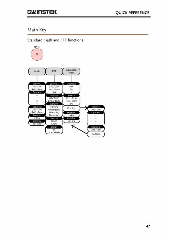
Math Key
Standard math and FFT functions.
FFTMath
CH1~CH4
Ref1~Ref4
Source 1
XXDiv
Position
+-×÷
Operator
CH1~CH4
Ref1~Ref4
Source 2
XX~XXV
Unit/Div
AdvancedMath
d/dt
∫dt
√
Operator
CH1~CH4
Ref1~Ref4
f(x)
Source
Edit f(x)
XXDiv
Position
XX~XX
Unit/Div
Hanning
Rectangular
Hamming
Blackman
Window
1X
X.XXXMHz
Zoom
CH1~CH4
Ref1~Ref4
f(x)
Source 1
dBV RMS
Linear RMS
Vertical
XXdB
XXDiv
Vertical
M
MATH
+-×÷
Operator
CH1~CH4
Source 2
Go Back
CH1~CH4
Source 2
GDS-2000A Series User Manual
48
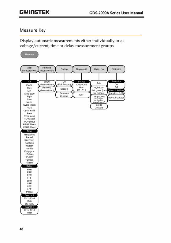
Measure Key
Display automatic measurements either individually or as voltage/current, time or delay measurement groups.
Remove Measurement
Gating Display All
Off
(Full Record)
Add Measurement
Pk-Pk
Max
Min
Amplitude
High
Low
Mean
Cycle Mean
RMS
Cycle RMS
Area
Cycle Area
ROVShoot
FOVShoot
RPREShoot
FPREShoot
V/I
Frequency
Period
RiseTime
FallTime
+Width
-Width
Dutycycle
+Pulses
-Pulses
+Edges
-Edges
Time
FRR
FRF
FFR
FFF
LRR
LRF
LFR
LFF
Phase
Delay
Screen
Between
Cursors
CH1~CH4
Math
D0~D15
Source 1
High-Low
Auto
High-Low:
Histogram (best
for pulses)
High-Low:Min-Max (all other
waveforms)
Set to
Defaults
CH1~CH4
Math
Source 2
Select
Measurement
Remove
Measurement
CH1~CH4
Math
D0~D15
Source
OFF
Statistics
On
Off
Statistics
Samples: 2~XX
Mean & Std Dev
Reset Statistics
Measure
QUICK REFERENCE
49
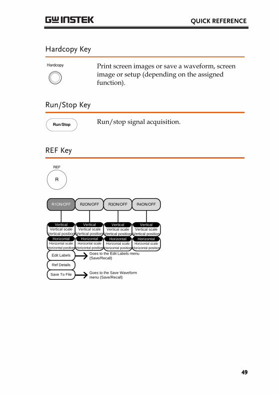
Hardcopy Key
Hardcopy
Print screen images or save a waveform, screen image or setup (depending on the assigned function).
Run/Stop Key
Run/Stop
Run/stop signal acquisition.
REF Key
R
REF
R2ON/OFF R3ON/OFF R4ON/OFFR1ON/OFF
Vertical scale
Vertical position
Vertical
Horizontal scale
Horizontal position
Horizontal
Edit Labels
Ref Details
Save To File Goes to the Save Waveform
menu (Save/Recall)
Goes to the Edit Labels menu
(Save/Recall)
Vertical scale
Vertical position
Vertical
Horizontal scale
Horizontal position
Horizontal
Vertical scale
Vertical position
Vertical
Horizontal scale
Horizontal position
Horizontal
Vertical scale
Vertical position
Vertical
Horizontal scale
Horizontal position
Horizontal
GDS-2000A Series User Manual
50
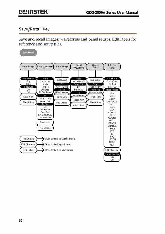
Save/Recall Key
Save and recall images, waveforms and panel setups. Edit labels for reference and setup files.
Save Waveform Save SetupRecall
WaveformRecallSetup
Edit FileLabel
Edit Label
Save Image
Png
Bmp
File Format
On
Off
Ink Saver
Save Now
File Utilites
Set1~Set20
Filename.set
CH1~CH4
Ref1~4
Set1~20
Label For
ACK
AD0
ADDR
ANALOG
BIT
CAS
CLK
CLOCK
CLR
COUNT
DATA
DTACK
ENABLE
HALT
INT
IN
IRQ
LATCH
LOAD
NMI
User Preset
Edit Character
CH1~CH4
Math
Ref1~4
D0~D15
All Displayed
From
Ref 1 ~ Ref4
Wave1~20
Lsf
Detail Csv
Fast Csv
LM Detail Csv
LM Fast Csv
To
To File
Save Now
File Utilites
Save Now
File Utilites
To File
To
Ref1~Ref4To
Wave1~20
Lsf
Fast Csv
From
From File
Recall Now
File Utilites
Edit Label
Set1~Set20
Filename.set
From File
From
Recall Now
File Utilites
Goes to the File Utilities menuFile Utilites
Goes to the Keypad menuEdit Character
Goes to the Edit label menuEdit Label
On
Off
Label Display
Save/Recall
QUICK REFERENCE
51
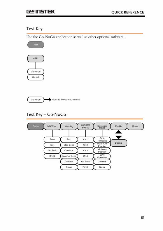
Test Key
Use the Go-NoGo application as well as other optional software.
APP.
Go-NoGo
Go-NoGo Goes to the Go-NoGo menu
Unistall
Test
Test Key – Go-NoGo
NG When ViolatingCompare
SourceReference
ModeEnableGoNo
CH1Enter Stop
Exit
Break
Go Back
Break
Stop Beep
Continue
Continue Beep
Go Back
Break
CH2
CH3
CH4
Go Back
Break
Auto
Tolerance
Maximum
Position
Minimum
Position
Save
Operation
Go Back
Break
Disable
GDS-2000A Series User Manual
52
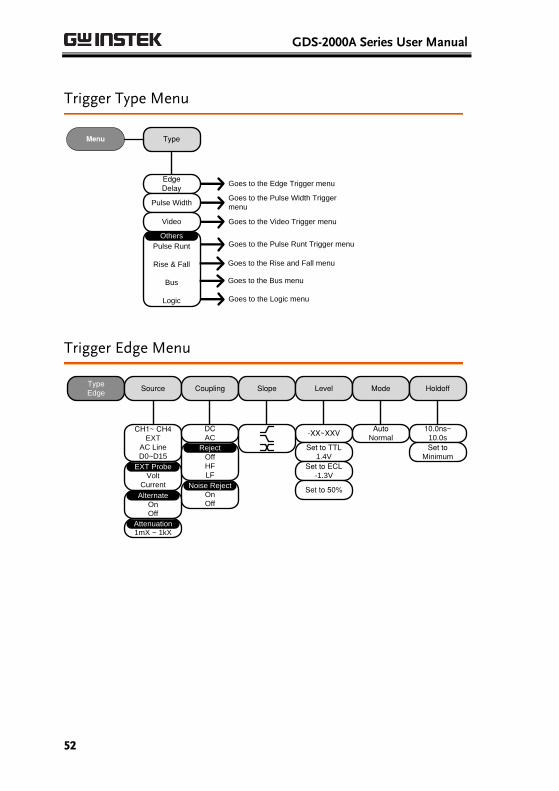
Trigger Type Menu
Menu Type
Pulse Runt
Rise & Fall
Bus
Logic
Others
EdgeDelay
Pulse Width
Video
Goes to the Edge Trigger menu
Goes to the Pulse Width Trigger
menu
Goes to the Video Trigger menu
Goes to the Pulse Runt Trigger menu
Goes to the Rise and Fall menu
Goes to the Bus menu
Goes to the Logic menu
Trigger Edge Menu
TypeEdge
Source Coupling Slope Level Mode Holdoff
CH1~ CH4EXT
AC Line
D0~D15
EXT Probe
Volt
Current
DCAC
-XX~XXV
Set to TTL1.4V
Set to ECL-1.3V
Set to 50%
AutoNormal
10.0ns~10.0s
Set toMinimum
EXT Probe
Off
HF
LF
Reject
On
Off
Noise Reject
On
Off
Alternate
1mX ~ 1kXAttenuation
QUICK REFERENCE
53
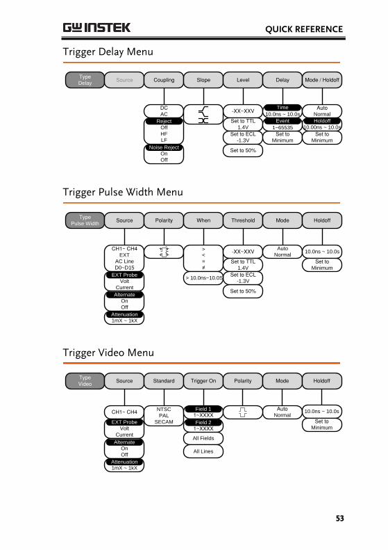
Trigger Delay Menu
DCAC
Off
HF
LF
Reject
On
Off
Noise Reject
TypeDelay
Source Coupling Slope Level Delay Mode / Holdoff
-XX~XXV
Set to TTL1.4V
Set to ECL-1.3V
Set to 50%
10.0ns ~ 10.0s
AutoNormal
Holdoff10.00ns ~ 10.0s
Set toMinimum
Time
1~65535
Event Holdoff
Set toMinimum
Trigger Pulse Width Menu
TypePulse Width
Source Polarity When Threshold Mode Holdoff
CH1~ CH4EXT
AC Line
D0~D15
><
=
≠
-XX~XXV
Set to TTL1.4V
Set to ECL-1.3V
Set to 50%
Auto
Normal10.0ns ~ 10.0s
> 10.0ns~10.0S EXT Probe
Volt
Current
EXT Probe
Set toMinimum
On
Off
Alternate
1mX ~ 1kXAttenuation
Trigger Video Menu
TypeVideo
Source Standard Trigger On Polarity Mode Holdoff
CH1~ CH4 NTSC
PAL
SECAM
1~XXXXAuto
Normal
All Fields
All Lines
EXT Probe
Volt
Current
EXT Probe
Field 1
1~XXXXField 2
10.0ns ~ 10.0s
Set toMinimum
On
Off
Alternate
1mX ~ 1kXAttenuation
GDS-2000A Series User Manual
54
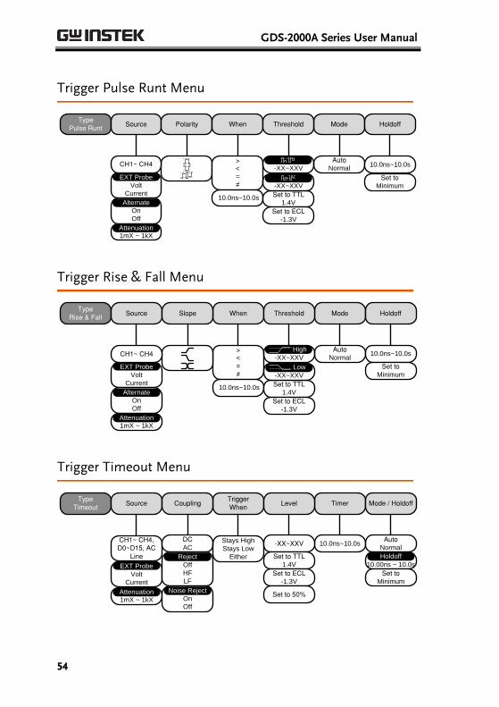
Trigger Pulse Runt Menu
TypePulse Runt
Source Polarity Mode Holdoff
AutoNormal
EXT Probe
Volt
Current
When
><
=
≠
10.0ns~10.0s
Threshold
Set to TTL1.4V
Set to ECL-1.3V
-XX~XXV
-XX~XXV
10.0ns~10.0s
Set toMinimum
On
Off
Alternate
CH1~ CH4
1mX ~ 1kXAttenuation
Trigger Rise & Fall Menu
TypeRise & Fall
Source Mode Holdoff
AutoNormal
When
><
=
≠
10.0ns~10.0s
Threshold
Set to TTL1.4V
Set to ECL-1.3V
-XX~XXV
-XX~XXV
Slope
High
Low
10.0ns~10.0s
Set toMinimum
EXT Probe
Volt
Current
On
Off
Alternate
CH1~ CH4
1mX ~ 1kXAttenuation
Trigger Timeout Menu
TypeTimeout
Source Timer
10.0ns~10.0s
TriggerWhen
EXT Probe
Volt
Current
CH1~ CH4, D0~D15, AC
Line
1mX ~ 1kXAttenuation
DCAC
Off
HF
LF
Reject
On
Off
Noise Reject
Coupling
Stays High
Stays Low
Either
Level
-XX~XXV
Set to TTL1.4V
Set to ECL-1.3V
Set to 50%
Mode / Holdoff
AutoNormal
Holdoff10.00ns ~ 10.0s
Holdoff
Set toMinimum
QUICK REFERENCE
55
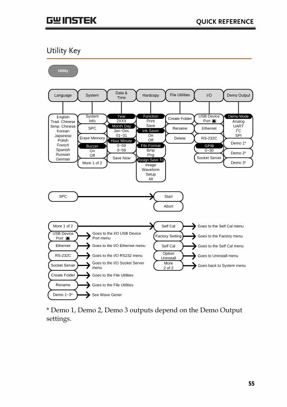
Utility Key
SystemData &Time
Hardcopy File Utilities I/OLanguage
English
Trad. Chinese
Simp. Chinese
Korean
Japanese
Polish
French
Spanish
Russian
German
Ethernet
RS-232C
System
Info
SPC
On
Off
Ink Saver
Save
FunctionCreate Folder
Rename
Delete
More 1 of 2
2XXXYear
Jan~Dec
01~31
Month Day
0~59
0~59
Hour Minute
Save Now
USB Device
Bmp
Png
File Format
Erase Memory
Image
Waveform
Setup
All
Assign Save ToSocket Server
More 1 of 2
Ethernet
RS-232C
USB Device
Port
Goes to the I/O USB Device
Port menu
Goes to the I/O Ethernet menu
Goes to the I/O RS232 menu
Socket Server
Create Folder
Goes to the I/O Socket Server
menu
Goes to the File Utilities
Rename Goes to the File Utilities
SPC Start
Abort
On
Off
Buzzer0~30GPIB
Demo Output
Analog
UART
I2C
SPI
Demo Mode
Demo 1*
Demo 2*
Demo 1~3* See Wave Gener
Self Cal
Factory Setting
Self Cal
Option
Uninstall
More
2 of 2 Goes back to System menu
Goes to Uninstall menu
Goes to the Self Cal menu
Goes to the Factory menu
Goes to the Self Cal menu
Utility
Port
Demo 3*
* Demo 1, Demo 2, Demo 3 outputs depend on the Demo Output settings.
GDS-2000A Series User Manual
56
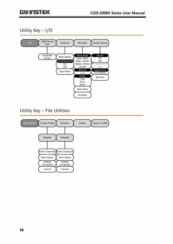
Utility Key – I/O
I/OUSB Device
PortEthernet RS-232C
Go Back
Save Now
On
Off
DHCP/BOOTP
2400, 4800,
9600, 19200,
38400, 57600,
115200
Baud Rate
1, 2
Stop Bit
Odd
Even
None
Parity
Back Space
Save Now
Socket Server
On
Off
Server
Current Port3000
0 to 65535Select Port
Set Port
ComputerPrinter
Utility Key – File Utilities
File Utilities Create Folder Rename Delete
Keypad
Enter Character
Back Space
Editing
Completed
Cancel
Keypad
Enter Character
Back Space
Editing
Completed
Cancel
Copy To USB
QUICK REFERENCE
57
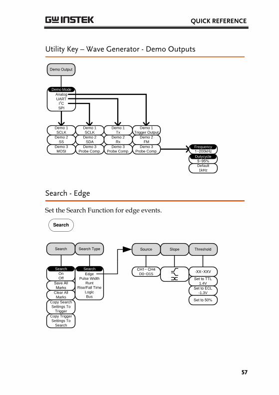
Utility Key – Wave Generator - Demo Outputs
Demo Output
Analog
UART
I2C
SPI
Demo Mode
Demo 1
SCLK
Demo 1
SCLK
Demo 1
Tx
Demo 1
Trigger Output
Demo 3
MOSI
Demo 3
Probe Comp.
Demo 3
Probe Comp.
Demo 3
Probe Comp.
Demo 2
SS
Demo 2
SDA
Demo 2
Rx
Demo 2
FM
1~200kHz
Default
1kHz
Frequency
5~95%Dutycycle
Search - Edge
Set the Search Function for edge events.
Search
On
Off
Search
Save All Marks
Clear All
Marks
Copy Trigger
Settings To
Search
Copy Search
Settings To
Trigger
Search Type
Edge
Pulse Width
Runt
Rise/Fall Time
Logic
Bus
Search
Slope Threshold
-XX~XXV
Set to TTL1.4V
Set to ECL-1.3V
Set to 50%
Search
Source
CH1~ CH4D0~D15
GDS-2000A Series User Manual
58
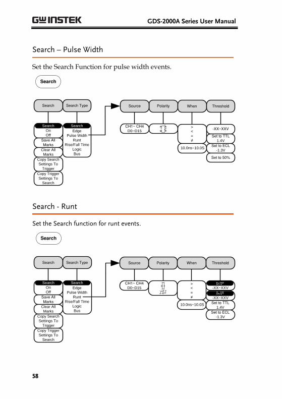
Search – Pulse Width
Set the Search Function for pulse width events.
Edge
Pulse Width
Runt
Rise/Fall Time
Logic
Bus
Search
Search
On
Off
Search
Save All Marks
Clear All
Marks
Copy Trigger
Settings To
Search
Copy Search
Settings To
Trigger
Search Type Polarity When
><
=
≠
10.0ns~10.0S
Threshold
-XX~XXV
Set to TTL1.4V
Set to ECL-1.3V
Set to 50%
Source
CH1~ CH4D0~D15
Search
Search - Runt
Set the Search function for runt events.
Edge
Pulse Width
Runt
Rise/Fall Time
Logic
Bus
Search
Polarity When
><
=
≠
10.0ns~10.0S
Threshold
Set to TTL1.4V
Set to ECL-1.3V
-XX~XXV
-XX~XXV
Search
On
Off
Search
Save All Marks
Clear All
Marks
Copy Trigger
Settings To
Search
Copy Search
Settings To
Trigger
Search Type
Search
Source
CH1~ CH4D0~D15
QUICK REFERENCE
59
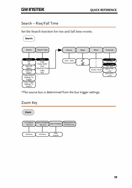
Search – Rise/Fall Time
Set the Search function for rise and fall time events.
Edge
Pulse Width
Runt
Rise/Fall Time
Logic
Bus
Search
Slope When
><
=
≠
10.0ns~10.0s
Threshold
Set to TTL1.4V
Set to ECL-1.3V
-XX~XXV
-XX~XXV
High
Low
Search
On
Off
Search
Save All Marks
Clear All
Marks
Copy Trigger
Settings To
Search
Copy Search
Settings To
Trigger
Search Type Source
CH1~ CH4
Search
*The source bus is determined from the bus trigger settings.
Zoom Key
H Position/
Set to 0
Zoom Position/ Set to 0
Zoom PositionReset Zoom &H POS to 0s
XXXXmsXXXXmsFine
Coarse
Zoom
GDS-2000A Series User Manual
60
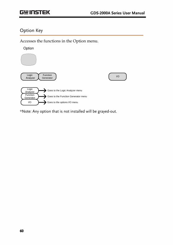
Option Key
Accesses the functions in the Option menu.
Function
GeneratorI/OLogic
Analyzer
Option
Logic
Analyzer
Function
Generator
Goes to the Logic Analyzer menu
Goes to the Function Generator menu
I/O Goes to the options I/O menu
*Note: Any option that is not installed will be grayed-out.
QUICK REFERENCE
61
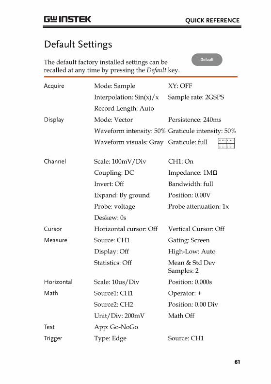
Default Settings
The default factory installed settings can be recalled at any time by pressing the Default key.
Default
Acquire Mode: Sample XY: OFF
Interpolation: Sin(x)/x Sample rate: 2GSPS
Record Length: Auto
Display Mode: Vector Persistence: 240ms
Waveform intensity: 50% Graticule intensity: 50%
Waveform visuals: Gray Graticule: full
Channel Scale: 100mV/Div CH1: On
Coupling: DC Impedance: 1MΩ
Invert: Off Bandwidth: full
Expand: By ground Position: 0.00V
Probe: voltage Probe attenuation: 1x
Deskew: 0s
Cursor Horizontal cursor: Off Vertical Cursor: Off
Measure Source: CH1 Gating: Screen
Display: Off High-Low: Auto
Statistics: Off Mean & Std Dev Samples: 2
Horizontal Scale: 10us/Div Position: 0.000s
Math Source1: CH1 Operator: +
Source2: CH2 Position: 0.00 Div
Unit/Div: 200mV Math Off
Test App: Go-NoGo
Trigger Type: Edge Source: CH1
GDS-2000A Series User Manual
62
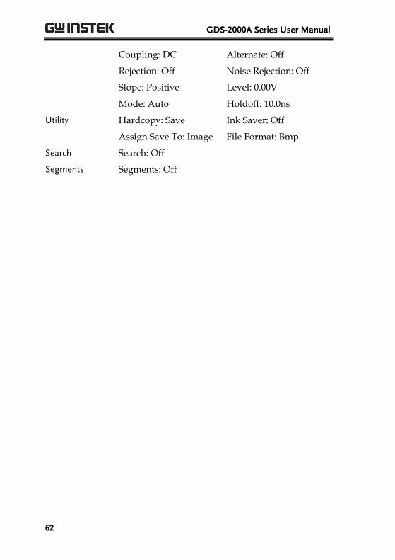
Coupling: DC Alternate: Off
Rejection: Off Noise Rejection: Off
Slope: Positive Level: 0.00V
Mode: Auto Holdoff: 10.0ns
Utility Hardcopy: Save Ink Saver: Off
Assign Save To: Image File Format: Bmp
Search Search: Off
Segments Segments: Off
QUICK REFERENCE
63
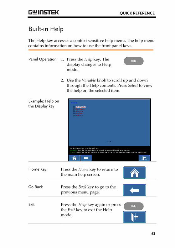
Built-in Help
The Help key accesses a context sensitive help menu. The help menu contains information on how to use the front panel keys.
Panel Operation 1. Press the Help key. The display changes to Help mode.
Help
2. Use the Variable knob to scroll up and down through the Help contents. Press Select to view the help on the selected item.
Example: Help on the Display key
Home Key Press the Home key to return to the main help screen.
Go Back Press the Back key to go to the previous menu page.
Exit Press the Help key again or press the Exit key to exit the Help mode.
Help
GDS-2000A Series User Manual
64
MEASUREMENT
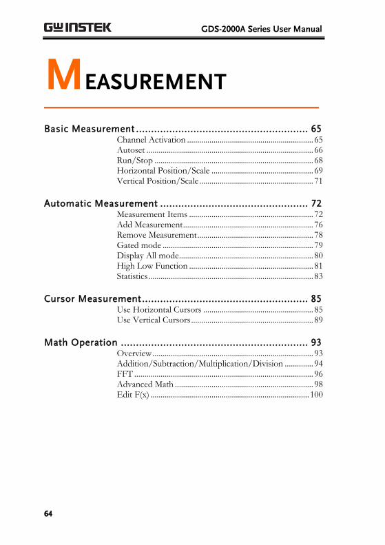
Basic Measurement ......................................................... 65 Channel Activation .............................................................. 65 Autoset .................................................................................. 66 Run/Stop .............................................................................. 68 Horizontal Position/Scale .................................................. 69 Vertical Position/Scale ........................................................ 71
Automatic Measurement ................................................. 72 Measurement Items ............................................................. 72 Add Measurement ................................................................ 76 Remove Measurement ......................................................... 78 Gated mode .......................................................................... 79 Display All mode .................................................................. 80 High Low Function ............................................................. 81 Statistics ................................................................................. 83
Cursor Measurement ....................................................... 85 Use Horizontal Cursors ...................................................... 85 Use Vertical Cursors ............................................................ 89
Math Operation .............................................................. 93 Overview ............................................................................... 93 Addition/Subtraction/Multiplication/Division .............. 94 FFT ........................................................................................ 96 Advanced Math .................................................................... 98 Edit F(x) .............................................................................. 100
MEASUREMENT
65
Basic Measurement This section describes the basic operations required in capturing and viewing the input signal. For more detailed operations, see the following chapters.
Cursor Measurement → from page 85
Configuration → from page 101
Before operating the oscilloscope, please see the Getting Started chapter, page 10.
Channel Activation
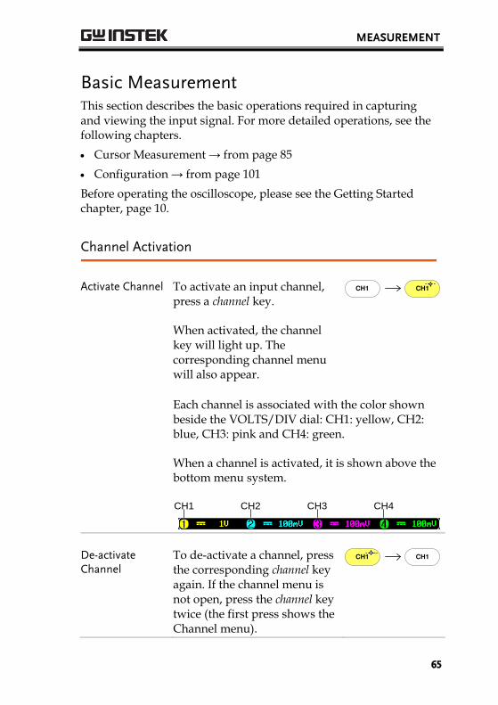
Activate Channel To activate an input channel, press a channel key.
When activated, the channel key will light up. The corresponding channel menu will also appear.
CH1CH1
Each channel is associated with the color shown beside the VOLTS/DIV dial: CH1: yellow, CH2: blue, CH3: pink and CH4: green.
When a channel is activated, it is shown above the bottom menu system.
CH1 CH3CH2 CH4
De-activate Channel
To de-activate a channel, press the corresponding channel key again. If the channel menu is not open, press the channel key twice (the first press shows the Channel menu).
CH1CH1
GDS-2000A Series User Manual
66
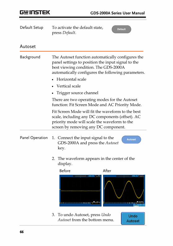
Default Setup To activate the default state, press Default.
Default
Autoset
Background The Autoset function automatically configures the panel settings to position the input signal to the best viewing condition. The GDS-2000A automatically configures the following parameters.
Horizontal scale
Vertical scale
Trigger source channel
There are two operating modes for the Autoset function: Fit Screen Mode and AC Priority Mode.
Fit Screen Mode will fit the waveform to the best scale, including any DC components (offset). AC priority mode will scale the waveform to the screen by removing any DC component.
Panel Operation 1. Connect the input signal to the GDS-2000A and press the Autoset key.
Autoset
2. The waveform appears in the center of the display.
Before
After
3. To undo Autoset, press Undo Autoset from the bottom menu.
MEASUREMENT
67
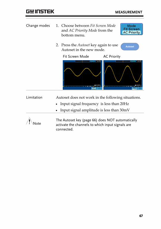
Change modes 1. Choose between Fit Screen Mode and AC Priority Mode from the bottom menu.
2. Press the Autoset key again to use Autoset in the new mode.
Autoset
Fit Screen Mode
AC Priority
Limitation Autoset does not work in the following situations.
Input signal frequency is less than 20Hz
Input signal amplitude is less than 30mV
Note The Autoset key (page 66) does NOT automatically activate the channels to which input signals are connected.
GDS-2000A Series User Manual
68
Run/Stop
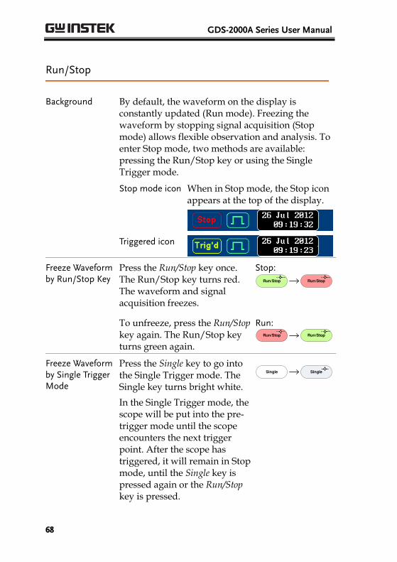
Background By default, the waveform on the display is constantly updated (Run mode). Freezing the waveform by stopping signal acquisition (Stop mode) allows flexible observation and analysis. To enter Stop mode, two methods are available: pressing the Run/Stop key or using the Single Trigger mode.
Stop mode icon When in Stop mode, the Stop icon appears at the top of the display.
Triggered icon
Freeze Waveform by Run/Stop Key
Press the Run/Stop key once. The Run/Stop key turns red. The waveform and signal acquisition freezes.
Stop: Run/Stop Run/Stop
To unfreeze, press the Run/Stop key again. The Run/Stop key turns green again.
Run: Run/Stop Run/Stop
Freeze Waveform by Single Trigger Mode
Press the Single key to go into the Single Trigger mode. The Single key turns bright white.
In the Single Trigger mode, the scope will be put into the pre-trigger mode until the scope encounters the next trigger point. After the scope has triggered, it will remain in Stop mode, until the Single key is pressed again or the Run/Stop key is pressed.
Single Single
MEASUREMENT
69
Waveform Operation
The waveform can be moved or scaled in both Run and Stop mode, but in different manners. For details, see page 130 (Horizontal position/scale) and page 137 (Vertical position/scale).
Horizontal Position/Scale
For more detailed configuration, see page 130.
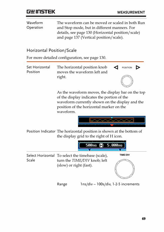
Set Horizontal Position
The horizontal position knob moves the waveform left and right.
POSITION
As the waveform moves, the display bar on the top of the display indicates the portion of the waveform currently shown on the display and the position of the horizontal marker on the waveform.
Position Indicator The horizontal position is shown at the bottom of the display grid to the right of H icon.
Select Horizontal Scale
To select the timebase (scale), turn the TIME/DIV knob; left (slow) or right (fast).
TIME/DIV
Range 1ns/div ~ 100s/div, 1-2-5 increments
GDS-2000A Series User Manual
70
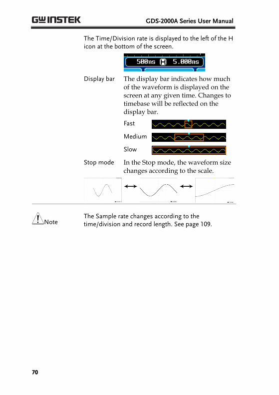
The Time/Division rate is displayed to the left of the H icon at the bottom of the screen.
Display bar The display bar indicates how much of the waveform is displayed on the screen at any given time. Changes to timebase will be reflected on the display bar.
Fast
Medium
Slow
Stop mode In the Stop mode, the waveform size changes according to the scale.
Note The Sample rate changes according to the time/division and record length. See page 109.
MEASUREMENT
71
Vertical Position/Scale
For more detailed configuration, see page 137.
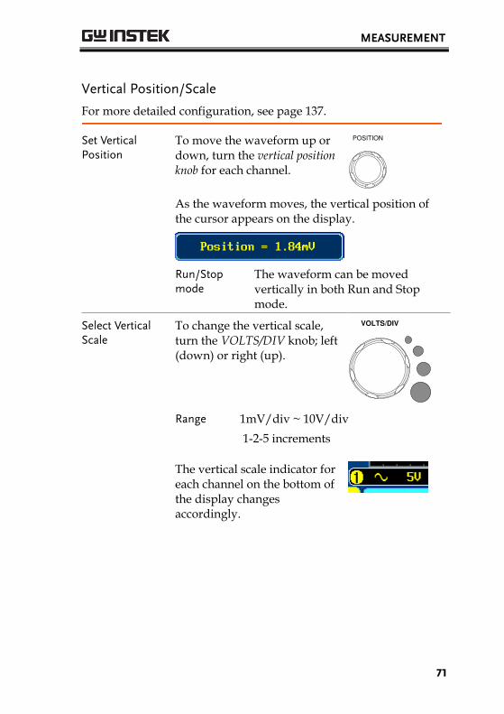
Set Vertical Position
To move the waveform up or down, turn the vertical position knob for each channel.
POSITION
As the waveform moves, the vertical position of the cursor appears on the display.
Run/Stop mode
The waveform can be moved vertically in both Run and Stop mode.
Select Vertical Scale
To change the vertical scale, turn the VOLTS/DIV knob; left (down) or right (up).
VOLTS/DIV
Range 1mV/div ~ 10V/div
1-2-5 increments
The vertical scale indicator for each channel on the bottom of the display changes accordingly.
GDS-2000A Series User Manual
72
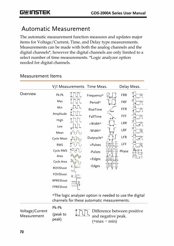
Automatic Measurement The automatic measurement function measures and updates major items for Voltage/Current, Time, and Delay type measurements. Measurements can be made with both the analog channels and the digital channels*, however the digital channels are only limited to a select number of time measurements. *Logic analyzer option needed for digital channels.
Measurement Items
V/I Measurements Time Meas. Delay Meas.
Overview
FPREShoot
RPREShoot
FOVShoot
ROVShoot
Cycle Area
Area
Cycle RMS
RMS
Cycle Mean
Mean
Low
High
Amplitude
Min
Max
Pk-Pk
Frequency*
Dutycycle*
-Width*
+Width*
FallTime
RiseTime
Period*
-Edges
+Edges
-Pulses
+Pulses
FRR
FRF
FFR
Phase
LFF
LFR
LRF
LRR
FFF
*The logic analyzer option is needed to use the digital channels for these automatic measurements.
Voltage/Current Measurement
Pk-Pk
(peak to peak)
Difference between positive and negative peak. (=max − min)
MEASUREMENT
73
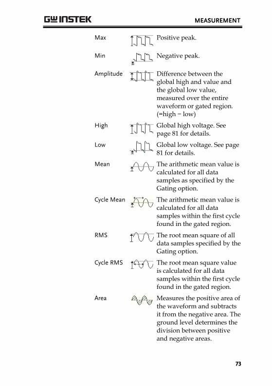
Max
Positive peak.
Min
Negative peak.
Amplitude
Difference between the global high and value and the global low value, measured over the entire waveform or gated region. (=high − low)
High
Global high voltage. See page 81 for details.
Low
Global low voltage. See page 81 for details.
Mean
The arithmetic mean value is calculated for all data samples as specified by the Gating option.
Cycle Mean
The arithmetic mean value is calculated for all data samples within the first cycle found in the gated region.
RMS
The root mean square of all data samples specified by the Gating option.
Cycle RMS
The root mean square value is calculated for all data samples within the first cycle found in the gated region.
Area
Measures the positive area of the waveform and subtracts it from the negative area. The ground level determines the division between positive and negative areas.
GDS-2000A Series User Manual
74
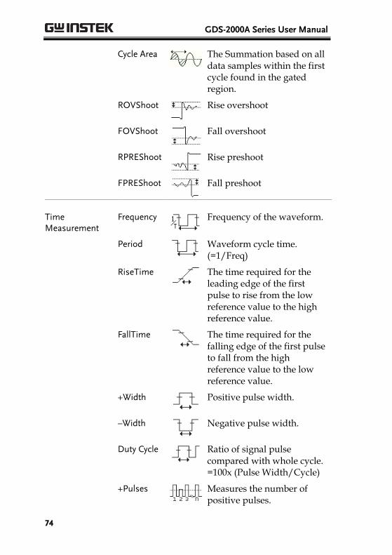
Cycle Area
The Summation based on all data samples within the first cycle found in the gated region.
ROVShoot
Rise overshoot
FOVShoot
Fall overshoot
RPREShoot
Rise preshoot
FPREShoot
Fall preshoot
Time Measurement
Frequency
Frequency of the waveform.
Period
Waveform cycle time. (=1/Freq)
RiseTime
The time required for the leading edge of the first pulse to rise from the low reference value to the high reference value.
FallTime
The time required for the falling edge of the first pulse to fall from the high reference value to the low reference value.
+Width
Positive pulse width.
–Width
Negative pulse width.
Duty Cycle
Ratio of signal pulse compared with whole cycle. =100x (Pulse Width/Cycle)
+Pulses
Measures the number of positive pulses.
MEASUREMENT
75
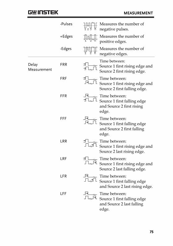
-Pulses
Measures the number of negative pulses.
+Edges
Measures the number of positive edges.
-Edges
Measures the number of negative edges.
Delay Measurement
FRR
Time between:
Source 1 first rising edge and Source 2 first rising edge.
FRF
Time between: Source 1 first rising edge and Source 2 first falling edge.
FFR
Time between: Source 1 first falling edge and Source 2 first rising edge.
FFF
Time between: Source 1 first falling edge and Source 2 first falling edge.
LRR
Time between: Source 1 first rising edge and Source 2 last rising edge.
LRF
Time between: Source 1 first rising edge and Source 2 last falling edge.
LFR
Time between: Source 1 first falling edge and Source 2 last rising edge.
LFF
Time between: Source 1 first falling edge and Source 2 last falling edge.
GDS-2000A Series User Manual
76
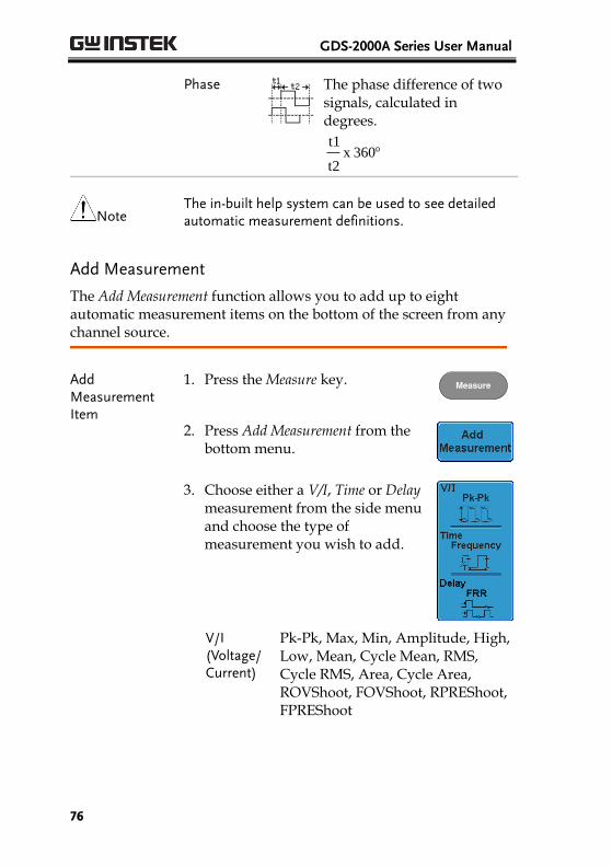
Phase
The phase difference of two signals, calculated in degrees.
360x t2
t1
Note The in-built help system can be used to see detailed automatic measurement definitions.
Add Measurement
The Add Measurement function allows you to add up to eight automatic measurement items on the bottom of the screen from any channel source.
Add Measurement Item
1. Press the Measure key. Measure
2. Press Add Measurement from the bottom menu.
3. Choose either a V/I, Time or Delay measurement from the side menu and choose the type of measurement you wish to add.
V/I (Voltage/ Current)
Pk-Pk, Max, Min, Amplitude, High, Low, Mean, Cycle Mean, RMS, Cycle RMS, Area, Cycle Area, ROVShoot, FOVShoot, RPREShoot, FPREShoot
MEASUREMENT
77
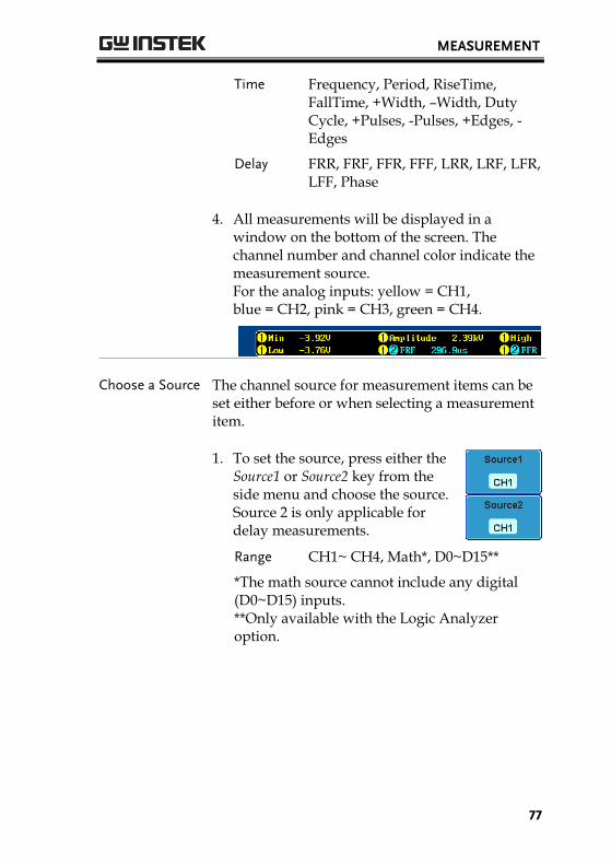
Time Frequency, Period, RiseTime, FallTime, +Width, –Width, Duty Cycle, +Pulses, -Pulses, +Edges, -Edges
Delay FRR, FRF, FFR, FFF, LRR, LRF, LFR, LFF, Phase
4. All measurements will be displayed in a window on the bottom of the screen. The channel number and channel color indicate the measurement source. For the analog inputs: yellow = CH1, blue = CH2, pink = CH3, green = CH4.
Choose a Source The channel source for measurement items can be set either before or when selecting a measurement item.
1. To set the source, press either the Source1 or Source2 key from the side menu and choose the source. Source 2 is only applicable for delay measurements.
Range CH1~ CH4, Math*, D0~D15**
*The math source cannot include any digital (D0~D15) inputs. **Only available with the Logic Analyzer option.
GDS-2000A Series User Manual
78
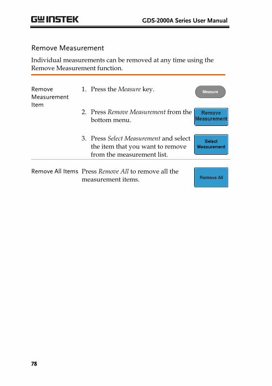
Remove Measurement
Individual measurements can be removed at any time using the Remove Measurement function.
Remove Measurement Item
1. Press the Measure key. Measure
2. Press Remove Measurement from the bottom menu.
3. Press Select Measurement and select the item that you want to remove from the measurement list.
Remove All Items Press Remove All to remove all the measurement items.
MEASUREMENT
79
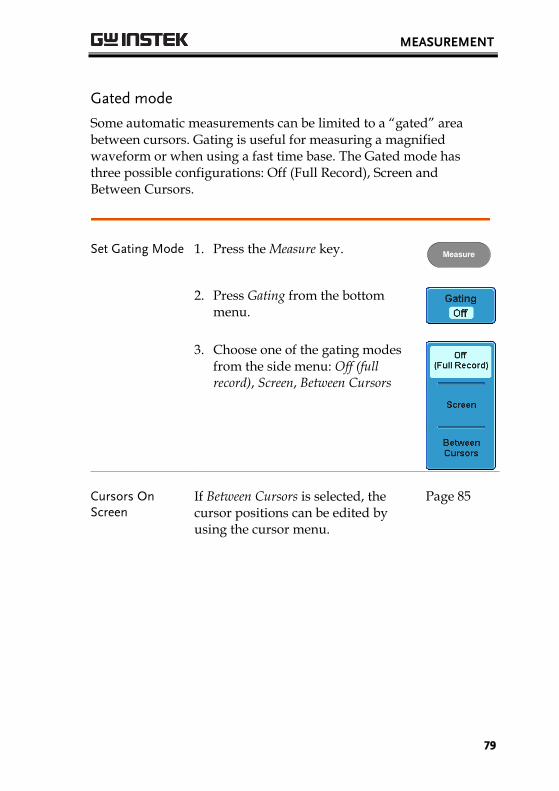
Gated mode
Some automatic measurements can be limited to a “gated” area between cursors. Gating is useful for measuring a magnified waveform or when using a fast time base. The Gated mode has three possible configurations: Off (Full Record), Screen and Between Cursors.
Set Gating Mode 1. Press the Measure key. Measure
2. Press Gating from the bottom menu.
3. Choose one of the gating modes from the side menu: Off (full record), Screen, Between Cursors
Cursors On Screen
If Between Cursors is selected, the cursor positions can be edited by using the cursor menu.
Page 85
GDS-2000A Series User Manual
80
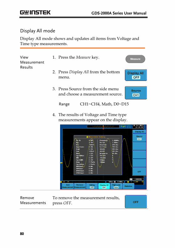
Display All mode
Display All mode shows and updates all items from Voltage and Time type measurements.
View Measurement Results
1. Press the Measure key. Measure
2. Press Display All from the bottom menu.
3. Press Source from the side menu and choose a measurement source.
Range CH1~CH4, Math, D0~D15
4. The results of Voltage and Time type measurements appear on the display.
Remove Measurements
To remove the measurement results, press OFF.
MEASUREMENT
81
Delay Measurements
Delay type measurement is not available in this mode as only one channel is used as the source. Use the Individual measurement mode (page 76) instead.
Digital Channels Only Frequency, Period, +Width, -Width and Duty Cycle measurements are supported for digital channels.
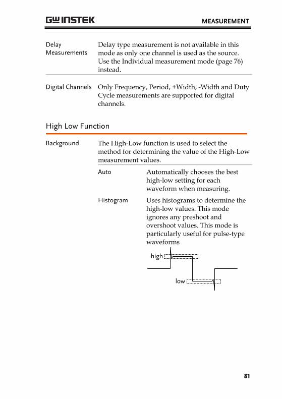
High Low Function
Background The High-Low function is used to select the method for determining the value of the High-Low measurement values.
Auto Automatically chooses the best high-low setting for each waveform when measuring.
Histogram Uses histograms to determine the high-low values. This mode ignores any preshoot and overshoot values. This mode is particularly useful for pulse-type waveforms
low
high

GDS-2000A Series User Manual
82
Min-max Sets the high-low values as the measured minimum or maximum measured values.
low
high
Set High-Low 1. Press the Measure key. Measure
2. Press High-Low from the bottom menu.
3. Select the type of High-Low settings from the side menu.
High-Low Settings: Histogram, Min-Max, Auto
Restore Default High-Low Settings
To return to the default High-Low settings, press Set to Defaults.
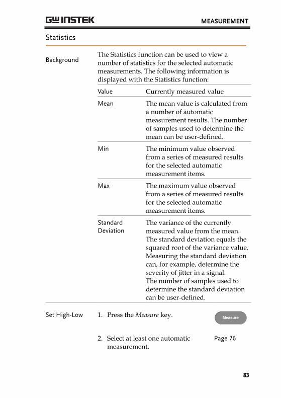
MEASUREMENT
83
Statistics
Background The Statistics function can be used to view a number of statistics for the selected automatic measurements. The following information is displayed with the Statistics function:
Value Currently measured value
Mean The mean value is calculated from a number of automatic measurement results. The number of samples used to determine the mean can be user-defined.
Min The minimum value observed from a series of measured results for the selected automatic measurement items.
Max The maximum value observed from a series of measured results for the selected automatic measurement items.
Standard Deviation
The variance of the currently measured value from the mean. The standard deviation equals the squared root of the variance value. Measuring the standard deviation can, for example, determine the severity of jitter in a signal. The number of samples used to determine the standard deviation can be user-defined.
Set High-Low 1. Press the Measure key. Measure
2. Select at least one automatic measurement.
Page 76
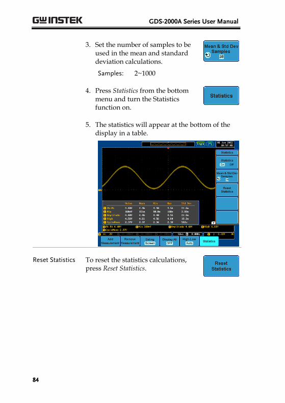
GDS-2000A Series User Manual
84
3. Set the number of samples to be used in the mean and standard deviation calculations.
Samples: 2~1000
4. Press Statistics from the bottom menu and turn the Statistics function on.
5. The statistics will appear at the bottom of the display in a table.
Reset Statistics To reset the statistics calculations, press Reset Statistics.

MEASUREMENT
85
Cursor Measurement Horizontal or vertical cursors are used to show the position and values of waveform measurements and math operation results. These results cover voltage, time, frequency and other math operations. When the cursors (horizontal, vertical or both) are activated, they will be shown on the main display unless turned off. (page 129).
Use Horizontal Cursors
Panel Operation/ Range
1. Press the Cursor key once. Cursor
2. Press H Cursor from the bottom menu if it is not already selected.
3. When the H Cursor is selected, repeatedly pressing the H Cursor key or the Select key will toggle which cursor is selected.
OR
Select
Range Description
Left cursor ( ) movable, right cursor position fixed
Right cursor ( ) movable, left cursor position fixed
Left and right cursor ( + ) movable together
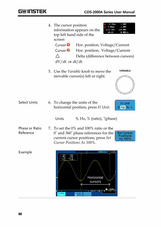
GDS-2000A Series User Manual
86
4. The cursor position
information appears on the top left hand side of the screen
Cursor Hor. position, Voltage/Current
Cursor Hor. position, Voltage/Current
Delta (difference between cursors)
dV/dt or dI/dt
5. Use the Variable knob to move the
movable cursor(s) left or right.
VARIABLE
Select Units 6. To change the units of the horizontal position, press H Unit.
Units S, Hz, % (ratio), ˚(phase)
Phase or Ratio Reference
7. To set the 0% and 100% ratio or the 0˚ and 360˚ phase references for the current cursor positions, press Set Cursor Positions As 100%.
Example
Horizontal
cursors
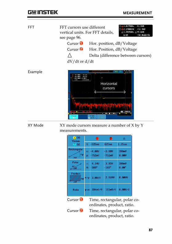
MEASUREMENT
87
FFT FFT cursors use different vertical units. For FFT details, see page 96.
Cursor Hor. position, dB/Voltage
Cursor Hor. Position, dB/Voltage
Delta (difference between cursors)
dV/dt or d/dt
Example
Horizontal
cursors
XY Mode XY mode cursors measure a number of X by Y measurements.
Cursor Time, rectangular, polar co-
ordinates, product, ratio.
Cursor Time, rectangular, polar co-ordinates, product, ratio.
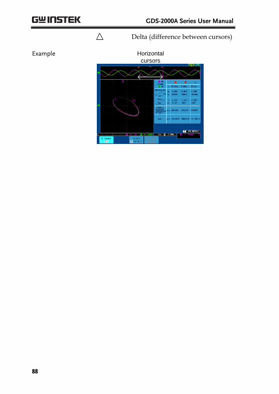
GDS-2000A Series User Manual
88
Delta (difference between cursors)
Example Horizontal
cursors
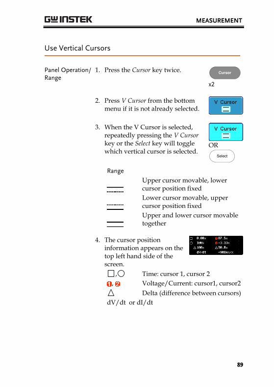
MEASUREMENT
89
Use Vertical Cursors
Panel Operation/ Range
1. Press the Cursor key twice. Cursor
x2
2. Press V Cursor from the bottom menu if it is not already selected.
3. When the V Cursor is selected, repeatedly pressing the V Cursor key or the Select key will toggle which vertical cursor is selected.
OR
Select
Range
Upper cursor movable, lower cursor position fixed
Lower cursor movable, upper cursor position fixed
Upper and lower cursor movable together
4. The cursor position
information appears on the top left hand side of the screen.
, Time: cursor 1, cursor 2
, Voltage/Current: cursor1, cursor2
Delta (difference between cursors)
dV/dt or dI/dt
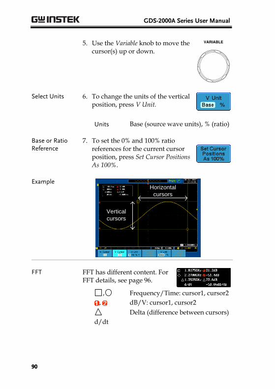
GDS-2000A Series User Manual
90
5. Use the Variable knob to move the
cursor(s) up or down.
VARIABLE
Select Units 6. To change the units of the vertical position, press V Unit.
Units Base (source wave units), % (ratio)
Base or Ratio Reference
7. To set the 0% and 100% ratio references for the current cursor position, press Set Cursor Positions As 100%.
Example Horizontal
cursors
Vertical
cursors
FFT FFT has different content. For FFT details, see page 96.
, Frequency/Time: cursor1, cursor2
, dB/V: cursor1, cursor2
Delta (difference between cursors)
d/dt
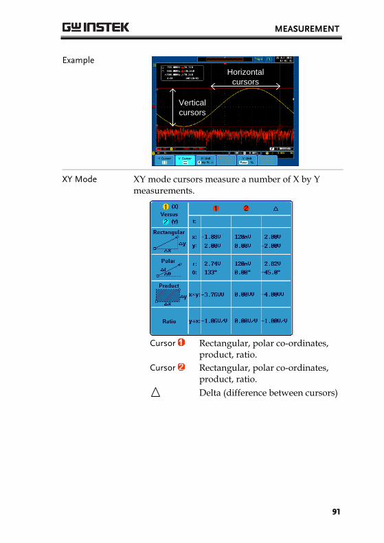
MEASUREMENT
91
Example
Horizontal
cursors
Vertical
cursors
XY Mode XY mode cursors measure a number of X by Y measurements.
Cursor Rectangular, polar co-ordinates,
product, ratio.
Cursor Rectangular, polar co-ordinates, product, ratio.
Delta (difference between cursors)
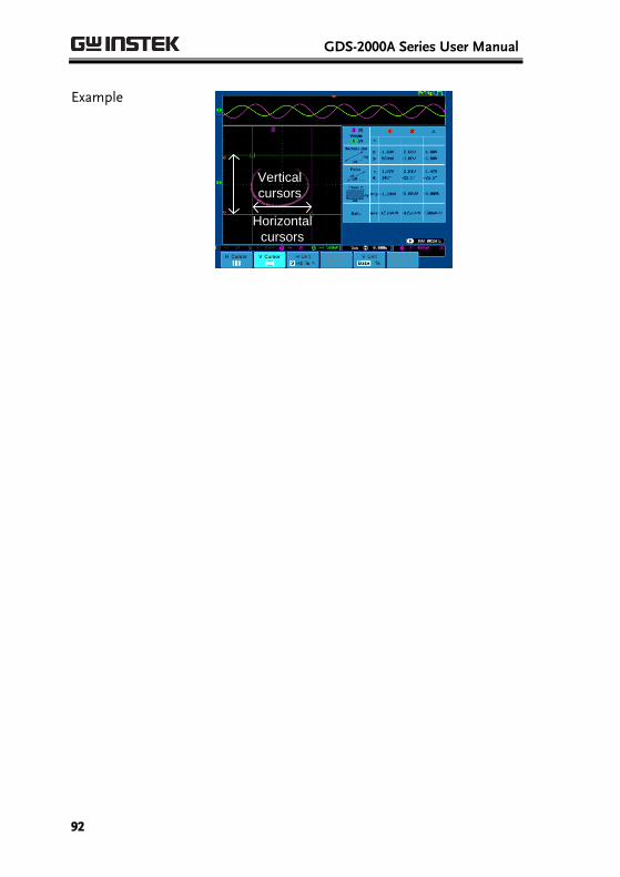
GDS-2000A Series User Manual
92
Example
Horizontal
cursors
Vertical
cursors
MEASUREMENT
93
Math Operation
Overview
Background Math operation runs addition, subtraction, multiplication, division, FFT, or certain advanced math functions for waveform manipulations using the input signals or reference waveforms (Ref1~4) and shows the result on the display. The resulted waveform characteristics can be measured using the cursors.
Addition (+) Adds the amplitude of two signals.
Source CH1~4, Ref1~4
Subtraction (–) Extracts the amplitude difference between two signals.
Source CH1~4, Ref1~4
Multiplication (×) Multiplies the amplitude of two signals.
Source CH1~4, Ref1~4
Division (÷) Divides the amplitude of two signals.
Source CH1~4, Ref1~4
FFT Runs FFT calculations on a signal. Four types of FFT windows are available: Hanning, Hamming, Rectangular, and Blackman.
Source CH1~4, Ref1~4, f(x)
d/dt Differentiate the source waveform.
Source CH1~4, Ref1~4, f(x)
∫dt Integrate the source waveform with respect to time.
Source CH1~4, Ref1~4, f(x)
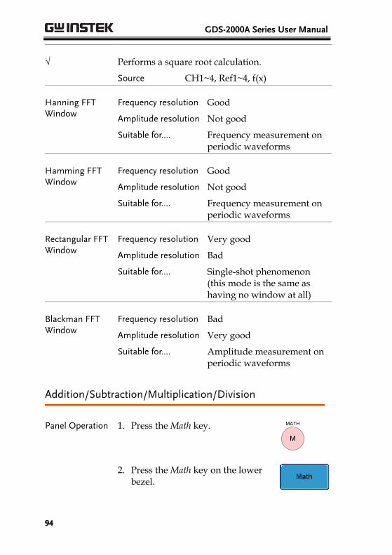
GDS-2000A Series User Manual
94
√ Performs a square root calculation.
Source CH1~4, Ref1~4, f(x)
Hanning FFT Window
Frequency resolution Good
Amplitude resolution Not good
Suitable for.... Frequency measurement on periodic waveforms
Hamming FFT Window
Frequency resolution Good
Amplitude resolution Not good
Suitable for.... Frequency measurement on periodic waveforms
Rectangular FFT Window
Frequency resolution Very good
Amplitude resolution Bad
Suitable for.... Single-shot phenomenon (this mode is the same as having no window at all)
Blackman FFT Window
Frequency resolution Bad
Amplitude resolution Very good
Suitable for.... Amplitude measurement on periodic waveforms
Addition/Subtraction/Multiplication/Division
Panel Operation 1. Press the Math key.
M
MATH
2. Press the Math key on the lower bezel.
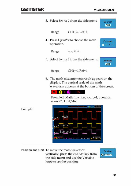
MEASUREMENT
95
3. Select Source 1 from the side menu
Range CH1~4, Ref~4
4. Press Operator to choose the math operation.
Range +, -, ×, ÷
5. Select Source 2 from the side menu.
Range CH1~4, Ref~4
6. The math measurement result appears on the display. The vertical scale of the math waveform appears at the bottom of the screen.
From left: Math function, source1, operator, source2, Unit/div
Example
Math
Source 2
Source 1
Position and Unit To move the math waveform vertically, press the Position key from the side menu and use the Variable knob to set the position.
GDS-2000A Series User Manual
96
Range –12.00 Div ~ +12.00 Div
To change the unit/div settings, press Unit/div, then use the Variable knob to change the unit/div.
The units that are displayed depend on which operator has been selected, and whether the probe for the selected channel has been set to voltage or current.
Operator: Unit/div:
Multiplication Division Addition/Subtraction
VV, AA or W V/V, A/A V or A
Turn Off Math To turn off the Math result from the display, press the Math key again. M
MATH
FFT
Panel Operation 1. Press the Math key.
M
MATH
2. Press FFT from the bottom menu.
3. Select the Source from the side menu.
Range CH1~4, Ref~4, f(x)*
*the f(x) source is set in the advanced math function, page 100.
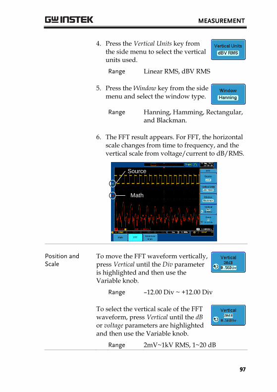
MEASUREMENT
97
4. Press the Vertical Units key from the side menu to select the vertical units used.
Range Linear RMS, dBV RMS
5. Press the Window key from the side menu and select the window type.
Range Hanning, Hamming, Rectangular, and Blackman.
6. The FFT result appears. For FFT, the horizontal scale changes from time to frequency, and the vertical scale from voltage/current to dB/RMS.
Source
Math
Position and Scale
To move the FFT waveform vertically, press Vertical until the Div parameter is highlighted and then use the Variable knob.
Range –12.00 Div ~ +12.00 Div
To select the vertical scale of the FFT waveform, press Vertical until the dB or voltage parameters are highlighted and then use the Variable knob.
Range 2mV~1kV RMS, 1~20 dB
GDS-2000A Series User Manual
98
Zoom and Offset To zoom into the FFT waveform, press Zoom until the x times parameter is highlighted and then use the Variable knob.
Range 1x ~ 20x
To horizontally offset the FFT waveform, press Zoom until the frequency parameter is highlighted and then use the Variable knob.
Clear FFT To clear the FFT result from the display, press the Math key again. M
MATH
Advanced Math
Background The advanced math function is used to perform a number of advanced math functions such as differentiation or integration of a source waveform.
The f(x) source function (as used in the FFT function) can also be set from the advanced menu.
Panel Operation 1. Press the Math key.
M
MATH
2. Press Advanced Math from the bottom menu.
3. Select the Operator from the side menu.
Range d/dt, ∫dt, √
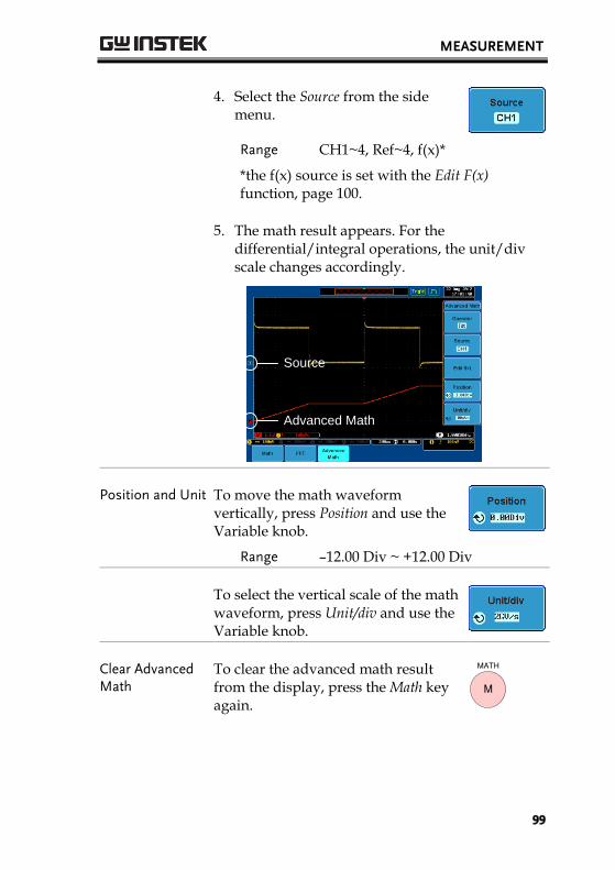
MEASUREMENT
99
4. Select the Source from the side menu.
Range CH1~4, Ref~4, f(x)*
*the f(x) source is set with the Edit F(x) function, page 100.
5. The math result appears. For the differential/integral operations, the unit/div scale changes accordingly.
Advanced Math
Source
Position and Unit To move the math waveform vertically, press Position and use the Variable knob.
Range –12.00 Div ~ +12.00 Div
To select the vertical scale of the math waveform, press Unit/div and use the Variable knob.
Clear Advanced Math
To clear the advanced math result from the display, press the Math key again.
M
MATH
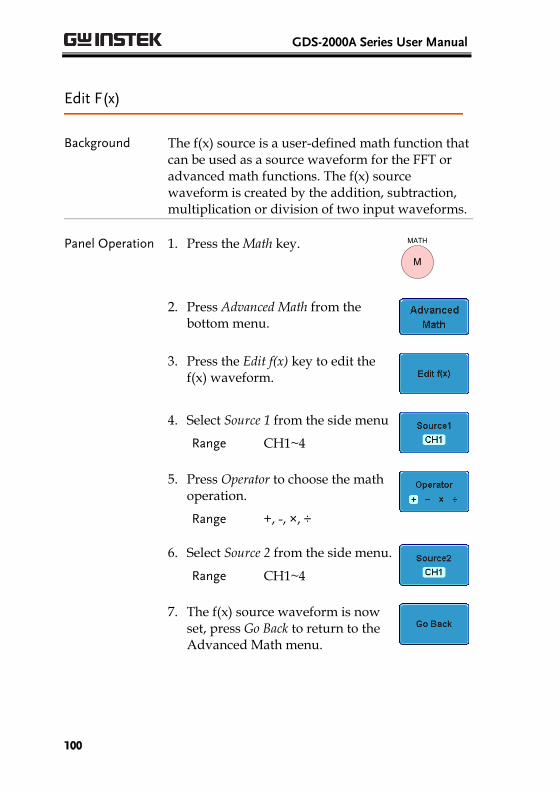
GDS-2000A Series User Manual
100
Edit F(x)
Background The f(x) source is a user-defined math function that can be used as a source waveform for the FFT or advanced math functions. The f(x) source waveform is created by the addition, subtraction, multiplication or division of two input waveforms.
Panel Operation 1. Press the Math key.
M
MATH
2. Press Advanced Math from the bottom menu.
3. Press the Edit f(x) key to edit the f(x) waveform.
4. Select Source 1 from the side menu
Range CH1~4
5. Press Operator to choose the math operation.
Range +, -, ×, ÷
6. Select Source 2 from the side menu.
Range CH1~4
7. The f(x) source waveform is now set, press Go Back to return to the Advanced Math menu.
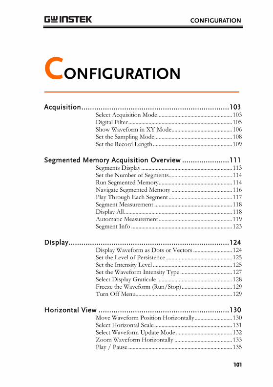
CONFIGURATION
101
CONFIGURATION
Acquisition ..................................................................... 103 Select Acquisition Mode .................................................... 103 Digital Filter ........................................................................ 105 Show Waveform in XY Mode .......................................... 106 Set the Sampling Mode ...................................................... 108 Set the Record Length ....................................................... 109
Segmented Memory Acquisition Overview ...................... 111 Segments Display ............................................................... 113 Set the Number of Segments ............................................ 114 Run Segmented Memory ................................................... 114 Navigate Segmented Memory .......................................... 116 Play Through Each Segment ............................................ 117 Segment Measurement ...................................................... 118 Display All ........................................................................... 118 Automatic Measurement ................................................... 119 Segment Info ...................................................................... 123
Display ........................................................................... 124 Display Waveform as Dots or Vectors ........................... 124 Set the Level of Persistence .............................................. 125 Set the Intensity Level ....................................................... 125 Set the Waveform Intensity Type .................................... 127 Select Display Graticule .................................................... 128 Freeze the Waveform (Run/Stop) ................................... 129 Turn Off Menu................................................................... 129
Horizontal View ............................................................. 130 Move Waveform Position Horizontally .......................... 130 Select Horizontal Scale ...................................................... 131 Select Waveform Update Mode ....................................... 132 Zoom Waveform Horizontally ........................................ 133 Play / Pause ........................................................................ 135
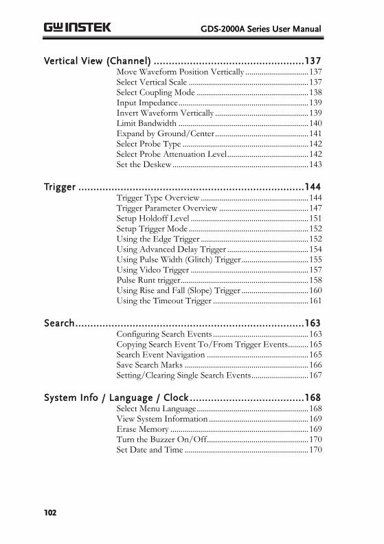
GDS-2000A Series User Manual
102
Vertical View (Channel) .................................................. 137 Move Waveform Position Vertically ............................... 137 Select Vertical Scale ........................................................... 137 Select Coupling Mode ....................................................... 138 Input Impedance ................................................................ 139 Invert Waveform Vertically .............................................. 139 Limit Bandwidth ................................................................ 140 Expand by Ground/Center .............................................. 141 Select Probe Type .............................................................. 142 Select Probe Attenuation Level ........................................ 142 Set the Deskew ................................................................... 143
Trigger ........................................................................... 144 Trigger Type Overview ..................................................... 144 Trigger Parameter Overview ............................................ 147 Setup Holdoff Level .......................................................... 151 Setup Trigger Mode ........................................................... 152 Using the Edge Trigger ..................................................... 152 Using Advanced Delay Trigger ........................................ 154 Using Pulse Width (Glitch) Trigger ................................. 155 Using Video Trigger .......................................................... 157 Pulse Runt trigger ............................................................... 158 Using Rise and Fall (Slope) Trigger ................................. 160 Using the Timeout Trigger ............................................... 161
Search ............................................................................ 163 Configuring Search Events ............................................... 163 Copying Search Event To/From Trigger Events .......... 165 Search Event Navigation .................................................. 165 Save Search Marks ............................................................. 166 Setting/Clearing Single Search Events ............................ 167
System Info / Language / Clock ...................................... 168 Select Menu Language ....................................................... 168 View System Information ................................................. 169 Erase Memory .................................................................... 169 Turn the Buzzer On/Off .................................................. 170 Set Date and Time ............................................................. 170
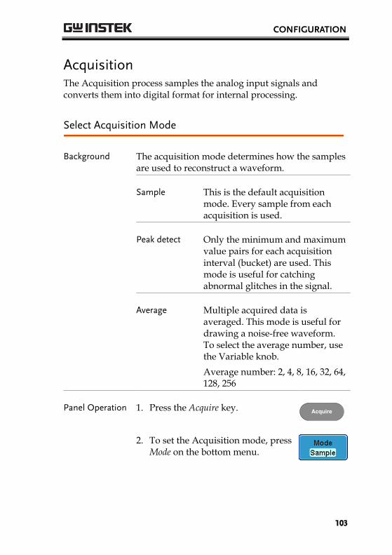
CONFIGURATION
103
Acquisition The Acquisition process samples the analog input signals and converts them into digital format for internal processing.
Select Acquisition Mode
Background The acquisition mode determines how the samples are used to reconstruct a waveform.
Sample This is the default acquisition
mode. Every sample from each acquisition is used.
Peak detect Only the minimum and maximum
value pairs for each acquisition interval (bucket) are used. This mode is useful for catching abnormal glitches in the signal.
Average Multiple acquired data is
averaged. This mode is useful for drawing a noise-free waveform. To select the average number, use the Variable knob.
Average number: 2, 4, 8, 16, 32, 64, 128, 256
Panel Operation 1. Press the Acquire key. Acquire
2. To set the Acquisition mode, press Mode on the bottom menu.

GDS-2000A Series User Manual
104
3. Select an acquisition mode from the side menu.
4. If Average was chosen, set the number of samples to be used for the average function.
Mode Sample, Peak Detect, Average
Average sample
2, 4, 8, 16, 32, 64, 128, 256
Example Sample
Peak Detect
Average (256 times)
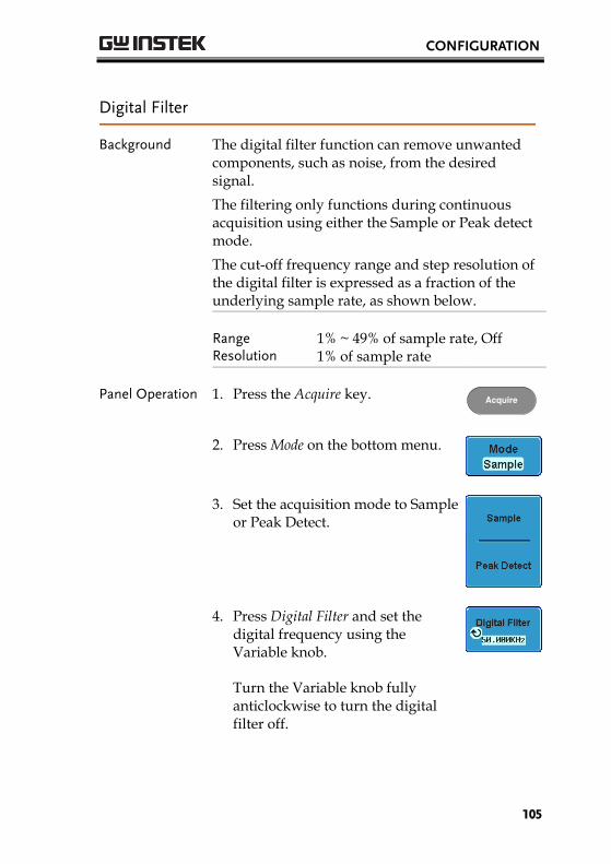
CONFIGURATION
105
Digital Filter
Background The digital filter function can remove unwanted components, such as noise, from the desired signal.
The filtering only functions during continuous acquisition using either the Sample or Peak detect mode.
The cut-off frequency range and step resolution of the digital filter is expressed as a fraction of the underlying sample rate, as shown below.
Range Resolution
1% ~ 49% of sample rate, Off 1% of sample rate
Panel Operation 1. Press the Acquire key. Acquire
2. Press Mode on the bottom menu.
3. Set the acquisition mode to Sample or Peak Detect.
4. Press Digital Filter and set the digital frequency using the Variable knob.
Turn the Variable knob fully anticlockwise to turn the digital filter off.
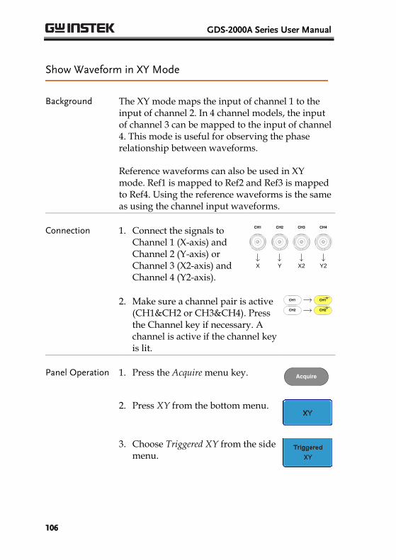
GDS-2000A Series User Manual
106
Show Waveform in XY Mode
Background The XY mode maps the input of channel 1 to the input of channel 2. In 4 channel models, the input of channel 3 can be mapped to the input of channel 4. This mode is useful for observing the phase relationship between waveforms.
Reference waveforms can also be used in XY mode. Ref1 is mapped to Ref2 and Ref3 is mapped to Ref4. Using the reference waveforms is the same as using the channel input waveforms.
Connection 1. Connect the signals to Channel 1 (X-axis) and Channel 2 (Y-axis) or Channel 3 (X2-axis) and Channel 4 (Y2-axis).
CH3CH2CH1 CH4
YX X2 Y2
2. Make sure a channel pair is active (CH1&CH2 or CH3&CH4). Press the Channel key if necessary. A channel is active if the channel key is lit.
CH1CH1 CH2CH2
Panel Operation 1. Press the Acquire menu key. Acquire
2. Press XY from the bottom menu.
3. Choose Triggered XY from the side menu.
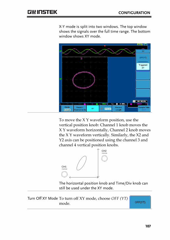
CONFIGURATION
107
X-Y mode is split into two windows. The top window shows the signals over the full time range. The bottom window shows XY mode.
To move the X Y waveform position, use the vertical position knob: Channel 1 knob moves the X Y waveform horizontally, Channel 2 knob moves the X Y waveform vertically. Similarly, the X2 and Y2 axis can be positioned using the channel 3 and channel 4 vertical position knobs.
POSITION
CH1
POSITION
CH2
The horizontal position knob and Time/Div knob can still be used under the XY mode.
Turn Off XY Mode To turn off XY mode, choose OFF (YT) mode.
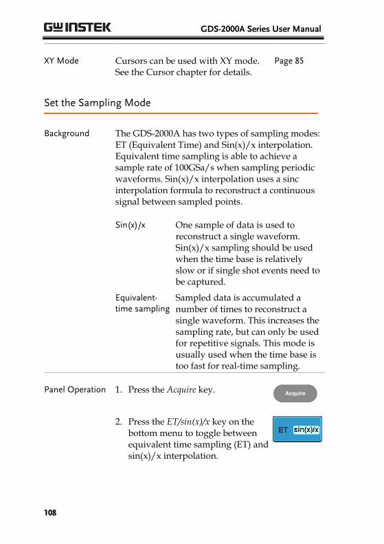
GDS-2000A Series User Manual
108
XY Mode Cursors can be used with XY mode. See the Cursor chapter for details.
Page 85
Set the Sampling Mode
Background The GDS-2000A has two types of sampling modes: ET (Equivalent Time) and Sin(x)/x interpolation. Equivalent time sampling is able to achieve a sample rate of 100GSa/s when sampling periodic waveforms. Sin(x)/x interpolation uses a sinc interpolation formula to reconstruct a continuous signal between sampled points.
Sin(x)/x One sample of data is used to reconstruct a single waveform. Sin(x)/x sampling should be used when the time base is relatively slow or if single shot events need to be captured.
Equivalent-time sampling
Sampled data is accumulated a number of times to reconstruct a single waveform. This increases the sampling rate, but can only be used for repetitive signals. This mode is usually used when the time base is too fast for real-time sampling.
Panel Operation 1. Press the Acquire key. Acquire
2. Press the ET/sin(x)/x key on the bottom menu to toggle between equivalent time sampling (ET) and sin(x)/x interpolation.
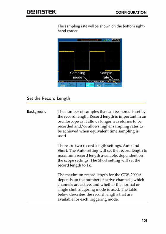
CONFIGURATION
109
The sampling rate will be shown on the bottom right-hand corner.
Sample
rate
Sampling
mode
Set the Record Length
Background The number of samples that can be stored is set by the record length. Record length is important in an oscilloscope as it allows longer waveforms to be recorded and/or allows higher sampling rates to be achieved when equivalent time sampling is used.
There are two record length settings, Auto and Short. The Auto setting will set the record length to maximum record length available, dependent on the scope settings. The Short setting will set the record length to 1 k.
The maximum record length for the GDS-2000A depends on the number of active channels, which channels are active, and whether the normal or single shot triggering mode is used. The table below describes the record lengths that are available for each triggering mode.
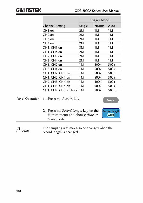
GDS-2000A Series User Manual
110
Channel Setting
Trigger Mode
Single Normal Auto
CH1 on 2M 1M 1M CH2 on 2M 1M 1M
CH3 on 2M 1M 1M CH4 on 2M 1M 1M CH1, CH3 on 2M 1M 1M
CH1, CH4 on 2M 1M 1M CH2, CH3 on 2M 1M 1M CH2, CH4 on 2M 1M 1M
CH1, CH2 on 1M 500k 500k CH3, CH4 on 1M 500k 500k CH1, CH2, CH3 on 1M 500k 500k
CH1, CH2, CH4 on 1M 500k 500k CH2, CH3, CH4 on 1M 500k 500k CH1, CH3, CH4 on 1M 500k 500k
CH1, CH2, CH3, CH4 on 1M 500k 500k
Panel Operation 1. Press the Acquire key. Acquire
2. Press the Record Length key on the bottom menu and choose Auto or Short mode.
Note The sampling rate may also be changed when the record length is changed.
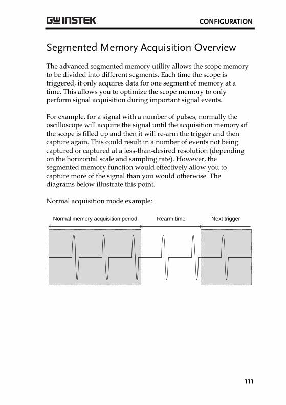
CONFIGURATION
111
Segmented Memory Acquisition Overview
The advanced segmented memory utility allows the scope memory to be divided into different segments. Each time the scope is triggered, it only acquires data for one segment of memory at a time. This allows you to optimize the scope memory to only perform signal acquisition during important signal events.
For example, for a signal with a number of pulses, normally the oscilloscope will acquire the signal until the acquisition memory of the scope is filled up and then it will re-arm the trigger and then capture again. This could result in a number of events not being captured or captured at a less-than-desired resolution (depending on the horizontal scale and sampling rate). However, the segmented memory function would effectively allow you to capture more of the signal than you would otherwise. The diagrams below illustrate this point.
Normal acquisition mode example:
Normal memory acquisition period Rearm time Next trigger

GDS-2000A Series User Manual
112
Segmented memory acquisition example:
Segment
n
Segment
n+1
Segment
n+2
Segment
n+3
Segment
n+4
Segment
n+5
As shown below, the memory is divided into segments to increase the number of events that can be effectively captured with the same acquisition memory. Also notice that the scope doesn’t need to rearm the trigger between each segment, this makes the segmented memory function especially useful for high speed signals. The time between each segment is also recorded so that accurate signal timing can also be measured.
The segmented memory function also supports automatic measurements for each segment or statistics for all the captured segments.
The Advanced Segment Memory Utility is applicable for both analog and digital channels.
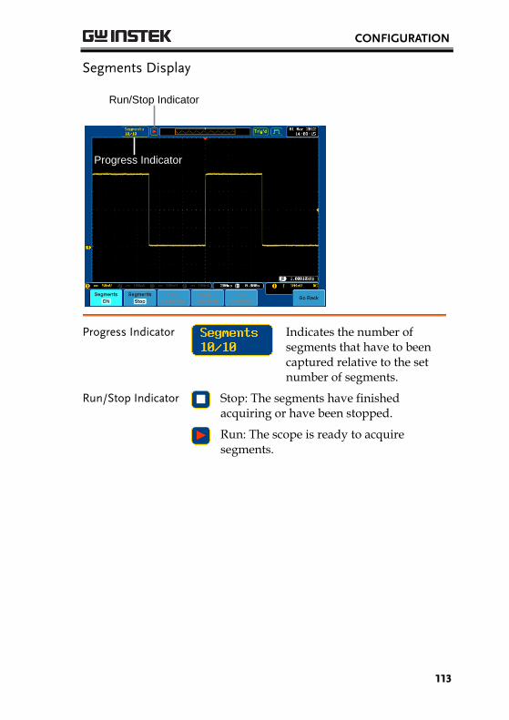
CONFIGURATION
113
Segments Display
Run/Stop Indicator
Progress Indicator
Progress Indicator
Indicates the number of segments that have to been captured relative to the set number of segments.
Run/Stop Indicator
Stop: The segments have finished acquiring or have been stopped.
Run: The scope is ready to acquire segments.
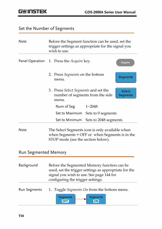
GDS-2000A Series User Manual
114
Set the Number of Segments
Note Before the Segment function can be used, set the trigger settings as appropriate for the signal you wish to use.
Panel Operation 1. Press the Acquire key. Acquire
2. Press Segments on the bottom menu.
3. Press Select Segments and set the number of segments from the side menu.
Num of Seg 1~2048
Set to Maximum Sets to 0 segments
Set to Minimum Sets to 2048 segments
Note The Select Segments icon is only available when when Segments = OFF or when Segments is in the STOP mode (see the section below).
Run Segmented Memory
Background Before the Segmented Memory function can be used, set the trigger settings as appropriate for the signal you wish to use. See page 144 for configuring the trigger settings.
Run Segments 1. Toggle Segments On from the bottom menu.
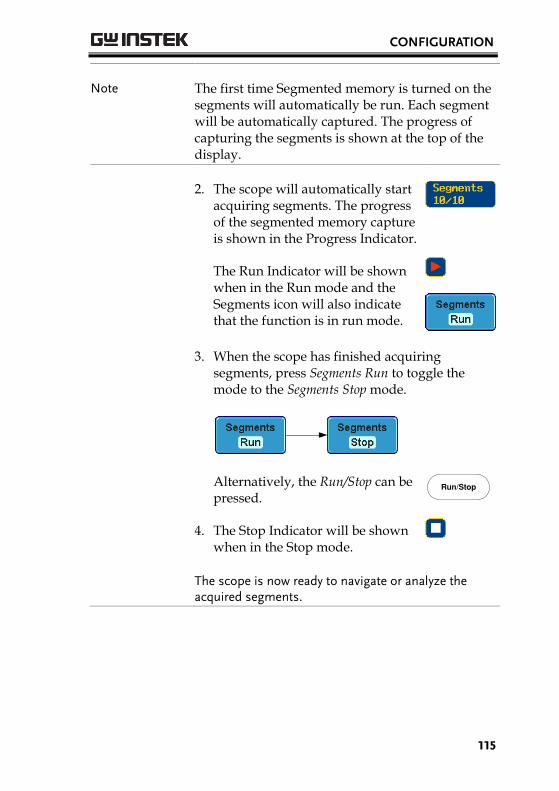
CONFIGURATION
115
Note The first time Segmented memory is turned on the segments will automatically be run. Each segment will be automatically captured. The progress of capturing the segments is shown at the top of the display.
2. The scope will automatically start acquiring segments. The progress of the segmented memory capture is shown in the Progress Indicator.
The Run Indicator will be shown when in the Run mode and the Segments icon will also indicate that the function is in run mode.
3. When the scope has finished acquiring segments, press Segments Run to toggle the mode to the Segments Stop mode.
Alternatively, the Run/Stop can be pressed.
4. The Stop Indicator will be shown when in the Stop mode.
Run/Stop
The scope is now ready to navigate or analyze the acquired segments.
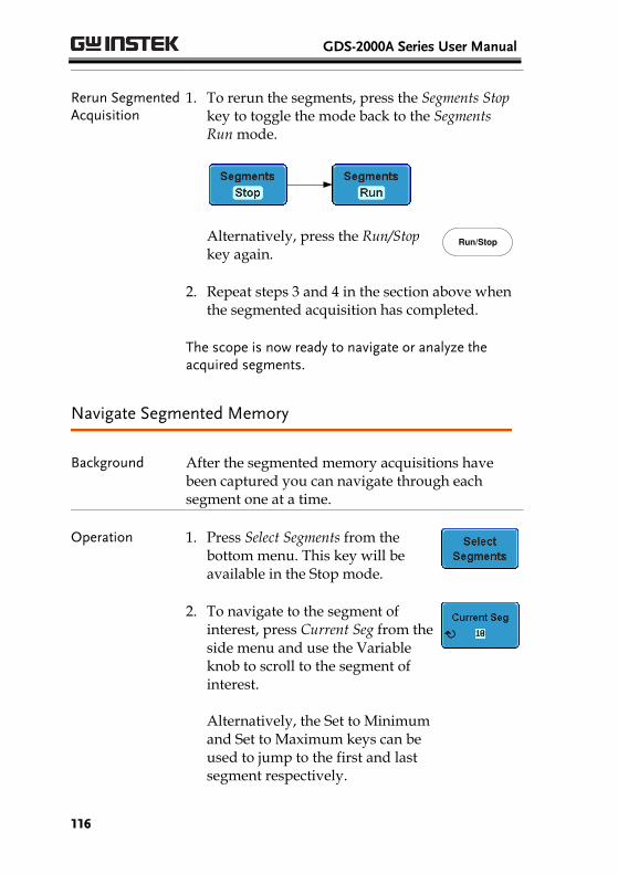
GDS-2000A Series User Manual
116
Rerun Segmented Acquisition
1. To rerun the segments, press the Segments Stop key to toggle the mode back to the Segments Run mode.
Alternatively, press the Run/Stop key again.
Run/Stop
2. Repeat steps 3 and 4 in the section above when the segmented acquisition has completed.
The scope is now ready to navigate or analyze the acquired segments.
Navigate Segmented Memory
Background After the segmented memory acquisitions have been captured you can navigate through each segment one at a time.
Operation 1. Press Select Segments from the bottom menu. This key will be available in the Stop mode.
2. To navigate to the segment of interest, press Current Seg from the side menu and use the Variable knob to scroll to the segment of interest. Alternatively, the Set to Minimum and Set to Maximum keys can be used to jump to the first and last segment respectively.
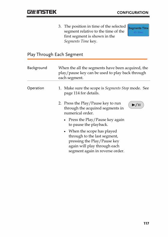
CONFIGURATION
117
3. The position in time of the selected segment relative to the time of the first segment is shown in the Segments Time key.
Play Through Each Segment
Background When the all the segments have been acquired, the play/pause key can be used to play back through each segment.
Operation 1. Make sure the scope is Segments Stop mode. See page 114 for details.
2. Press the Play/Pause key to run through the acquired segments in numerical order.
Press the Play/Pause key again to pause the playback.
When the scope has played through to the last segment, pressing the Play/Pause key again will play through each segment again in reverse order.
GDS-2000A Series User Manual
118
Segment Measurement
Background The Segmented memory function can be used in conjunction with the automatic measurements in the Measurement menu. Please note that digital channels are not supported for measurement using segments.
Display All The Display All function will show all
the acquired segments simultaneously.
Segments Measure
This function will either perform statistics calculations on the segments or tabulate a list of the measurement results.
Segments Info
Provides configuration information common for all the acquired memory segments.
Display All
Operation 1. Press Analyze Segments from the bottom menu. Note: This key will only be available in the Stop mode.
2. Press Display All
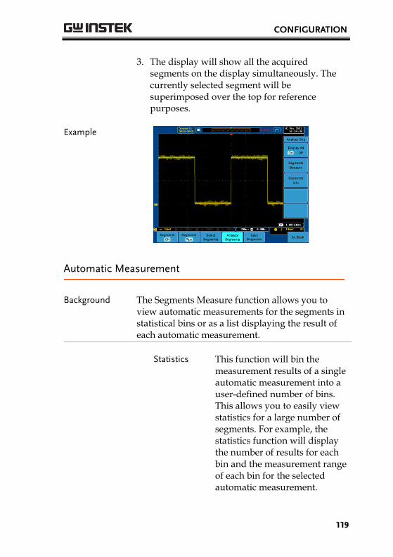
CONFIGURATION
119
3. The display will show all the acquired segments on the display simultaneously. The currently selected segment will be superimposed over the top for reference purposes.
Example
Automatic Measurement
Background The Segments Measure function allows you to view automatic measurements for the segments in statistical bins or as a list displaying the result of each automatic measurement.
Statistics This function will bin the
measurement results of a single automatic measurement into a user-defined number of bins. This allows you to easily view statistics for a large number of segments. For example, the statistics function will display the number of results for each bin and the measurement range of each bin for the selected automatic measurement.
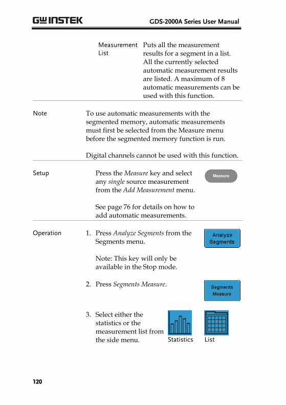
GDS-2000A Series User Manual
120
Measurement List
Puts all the measurement results for a segment in a list. All the currently selected automatic measurement results are listed. A maximum of 8 automatic measurements can be used with this function.
Note To use automatic measurements with the segmented memory, automatic measurements must first be selected from the Measure menu before the segmented memory function is run.
Digital channels cannot be used with this function.
Setup Press the Measure key and select any single source measurement from the Add Measurement menu. See page 76 for details on how to add automatic measurements.
Measure
Operation 1. Press Analyze Segments from the Segments menu. Note: This key will only be available in the Stop mode.
2. Press Segments Measure.
3. Select either the statistics or the measurement list from the side menu.
Statistics
List
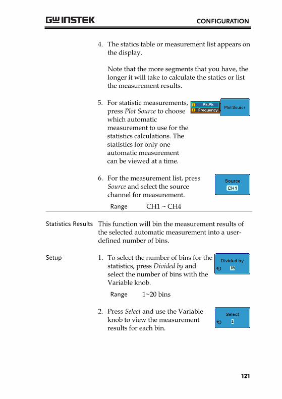
CONFIGURATION
121
4. The statics table or measurement list appears on the display.
Note that the more segments that you have, the longer it will take to calculate the statics or list the measurement results.
5. For statistic measurements, press Plot Source to choose which automatic measurement to use for the statistics calculations. The statistics for only one automatic measurement can be viewed at a time.
6. For the measurement list, press Source and select the source channel for measurement.
Range CH1 ~ CH4
Statistics Results This function will bin the measurement results of the selected automatic measurement into a user-defined number of bins.
Setup 1. To select the number of bins for the statistics, press Divided by and select the number of bins with the Variable knob.
Range 1~20 bins
2. Press Select and use the Variable knob to view the measurement results for each bin.
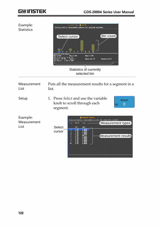
GDS-2000A Series User Manual
122
Example: Statistics
Statistics of currently
selected bin
Select cursor Bin count
Measurement List
Puts all the measurement results for a segment in a list.
Setup 1. Press Select and use the variable knob to scroll through each segment.
Example: Measurement List
Select
cursor
Measurement results
Measurement types
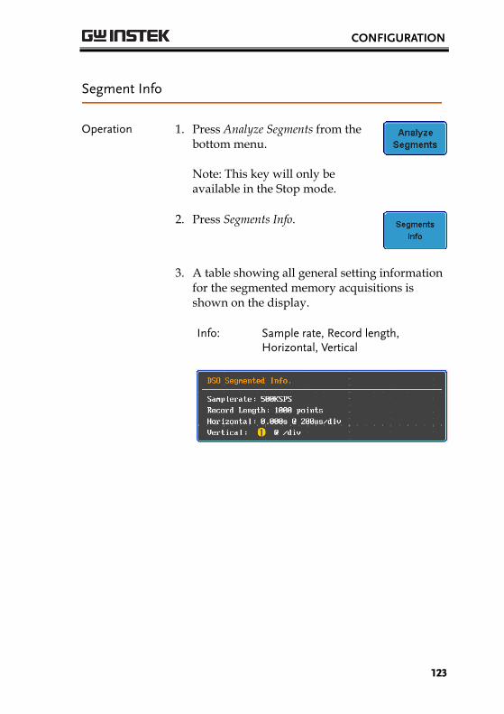
CONFIGURATION
123
Segment Info
Operation 1. Press Analyze Segments from the bottom menu. Note: This key will only be available in the Stop mode.
2. Press Segments Info.
3. A table showing all general setting information for the segmented memory acquisitions is shown on the display.
Info: Sample rate, Record length,
Horizontal, Vertical
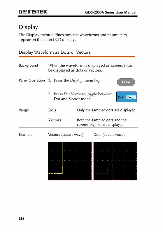
GDS-2000A Series User Manual
124
Display The Display menu defines how the waveforms and parameters appear on the main LCD display.
Display Waveform as Dots or Vectors
Background When the waveform is displayed on screen, it can be displayed as dots or vectors.
Panel Operation 1. Press the Display menu key. Display
2. Press Dot Vector to toggle between Dot and Vector mode.
Range Dots Only the sampled dots are displayed.
Vectors Both the sampled dots and the connecting line are displayed.
Example: Vectors (square wave) Dots (square wave)
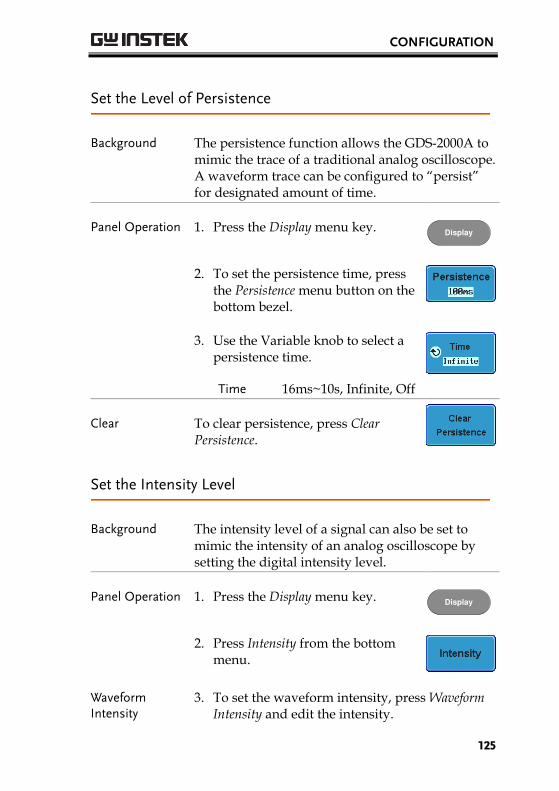
CONFIGURATION
125
Set the Level of Persistence
Background The persistence function allows the GDS-2000A to mimic the trace of a traditional analog oscilloscope. A waveform trace can be configured to “persist” for designated amount of time.
Panel Operation 1. Press the Display menu key. Display
2. To set the persistence time, press the Persistence menu button on the bottom bezel.
3. Use the Variable knob to select a persistence time.
Time 16ms~10s, Infinite, Off
Clear To clear persistence, press Clear Persistence.
Set the Intensity Level
Background The intensity level of a signal can also be set to mimic the intensity of an analog oscilloscope by setting the digital intensity level.
Panel Operation 1. Press the Display menu key. Display
2. Press Intensity from the bottom menu.
Waveform Intensity
3. To set the waveform intensity, press Waveform Intensity and edit the intensity.
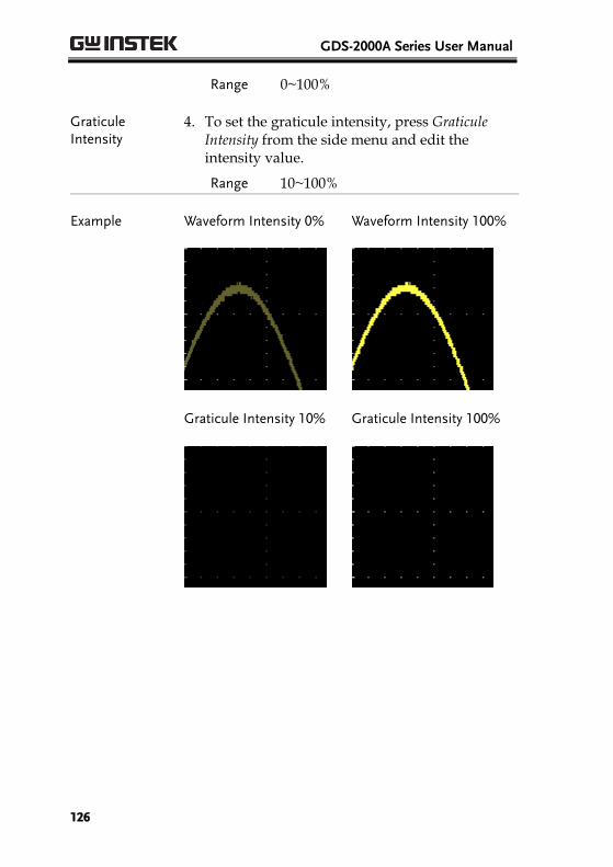
GDS-2000A Series User Manual
126
Range 0~100%
Graticule Intensity
4. To set the graticule intensity, press Graticule Intensity from the side menu and edit the intensity value.
Range 10~100%
Example Waveform Intensity 0% Waveform Intensity 100%
Graticule Intensity 10% Graticule Intensity 100%
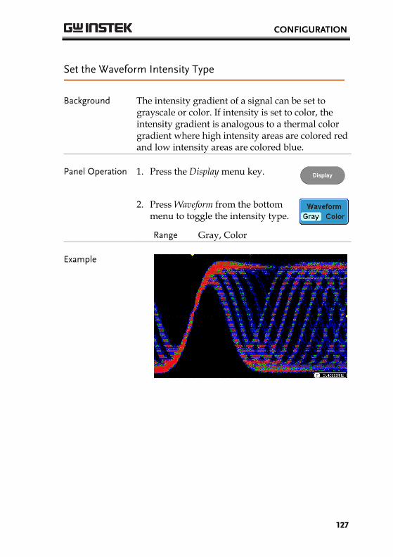
CONFIGURATION
127
Set the Waveform Intensity Type
Background The intensity gradient of a signal can be set to grayscale or color. If intensity is set to color, the intensity gradient is analogous to a thermal color gradient where high intensity areas are colored red and low intensity areas are colored blue.
Panel Operation 1. Press the Display menu key. Display
2. Press Waveform from the bottom menu to toggle the intensity type.
Range Gray, Color
Example
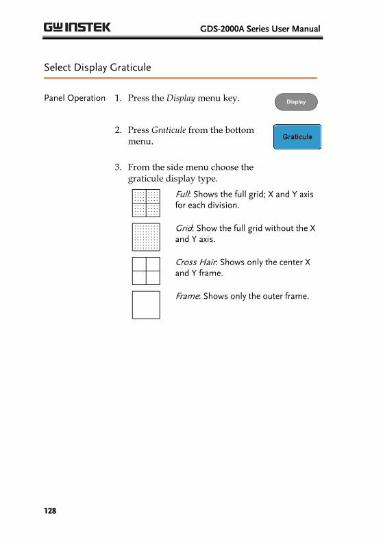
GDS-2000A Series User Manual
128
Select Display Graticule
Panel Operation 1. Press the Display menu key. Display
2. Press Graticule from the bottom menu.
3. From the side menu choose the graticule display type.
Full: Shows the full grid; X and Y axis for each division.
Grid: Show the full grid without the X and Y axis.
Cross Hair: Shows only the center X and Y frame.
Frame: Shows only the outer frame.
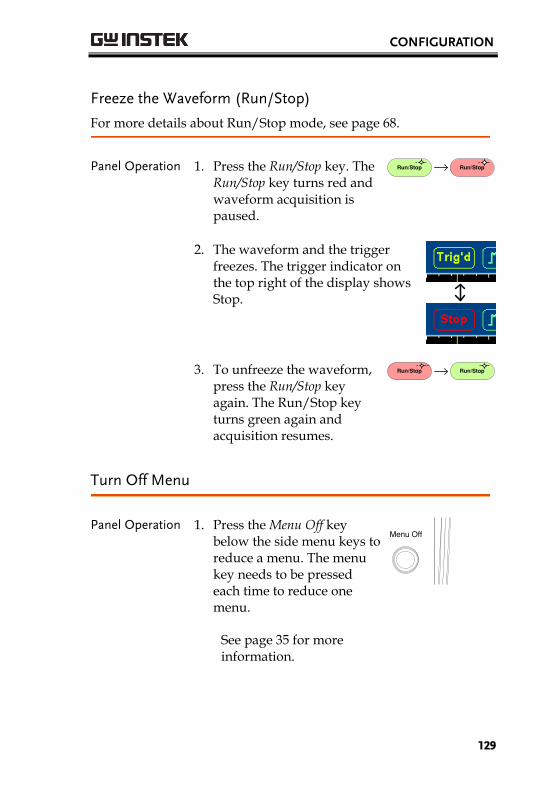
CONFIGURATION
129
Freeze the Waveform (Run/Stop)
For more details about Run/Stop mode, see page 68.
Panel Operation 1. Press the Run/Stop key. The Run/Stop key turns red and waveform acquisition is paused.
Run/Stop Run/Stop
2. The waveform and the trigger freezes. The trigger indicator on the top right of the display shows Stop.
3. To unfreeze the waveform, press the Run/Stop key again. The Run/Stop key turns green again and acquisition resumes.
Run/Stop Run/Stop
Turn Off Menu
Panel Operation 1. Press the Menu Off key below the side menu keys to reduce a menu. The menu key needs to be pressed each time to reduce one menu.
See page 35 for more information.
Menu Off
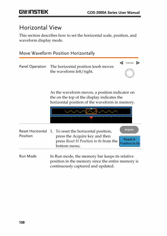
GDS-2000A Series User Manual
130
Horizontal View This section describes how to set the horizontal scale, position, and waveform display mode.
Move Waveform Position Horizontally
Panel Operation The horizontal position knob moves the waveform left/right.
POSITION
As the waveform moves, a position indicator on the on the top of the display indicates the horizontal position of the waveform in memory.
Reset Horizontal Position
1. To reset the horizontal position, press the Acquire key and then press Reset H Position to 0s from the bottom menu.
Acquire
Run Mode
In Run mode, the memory bar keeps its relative position in the memory since the entire memory is continuously captured and updated.
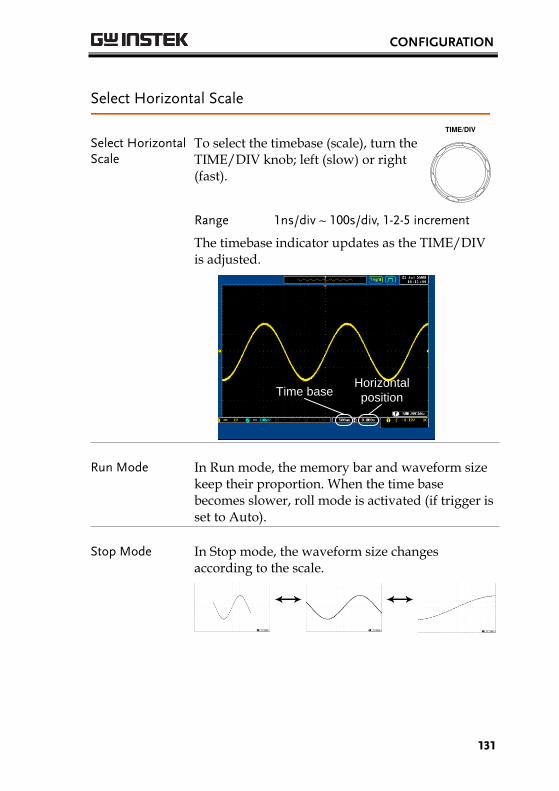
CONFIGURATION
131
Select Horizontal Scale
Select Horizontal Scale
To select the timebase (scale), turn the TIME/DIV knob; left (slow) or right (fast).
TIME/DIV
Range 1ns/div ~ 100s/div, 1-2-5 increment
The timebase indicator updates as the TIME/DIV is adjusted.
Horizontal
positionTime base
Run Mode In Run mode, the memory bar and waveform size keep their proportion. When the time base becomes slower, roll mode is activated (if trigger is set to Auto).
Stop Mode In Stop mode, the waveform size changes according to the scale.
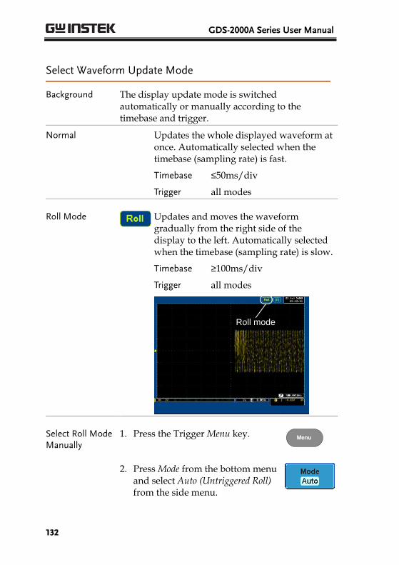
GDS-2000A Series User Manual
132
Select Waveform Update Mode
Background The display update mode is switched automatically or manually according to the timebase and trigger.
Normal Updates the whole displayed waveform at once. Automatically selected when the timebase (sampling rate) is fast.
Timebase ≤50ms/div
Trigger all modes
Roll Mode Updates and moves the waveform gradually from the right side of the display to the left. Automatically selected when the timebase (sampling rate) is slow.
Timebase ≥100ms/div
Trigger all modes
Roll mode
Select Roll Mode Manually
1. Press the Trigger Menu key. Menu
2. Press Mode from the bottom menu and select Auto (Untriggered Roll) from the side menu.

CONFIGURATION
133
Zoom Waveform Horizontally
Background When in Zoom mode, the screen is split into 2 sections. The top of the display shows the full record length, with the bottom of the screen showing the normal view.
Panel Operation 1. Press the Zoom key. Zoom
2. The Zoom mode screen appears.
Zoom time
base
Horizontal
position
Zoom
window
Horizontal Navigation
To scroll the waveform left or right, use the Variable Position knob.
VARIABLE
To reset the horizontal position, press H Position/Set to 0.
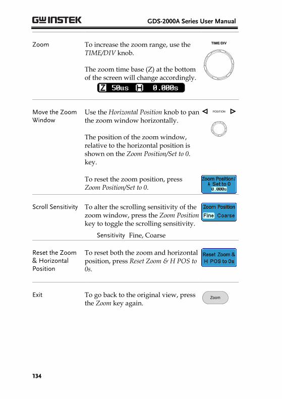
GDS-2000A Series User Manual
134
Zoom To increase the zoom range, use the TIME/DIV knob.
The zoom time base (Z) at the bottom of the screen will change accordingly.
TIME/DIV
Move the Zoom Window
Use the Horizontal Position knob to pan the zoom window horizontally. The position of the zoom window, relative to the horizontal position is shown on the Zoom Position/Set to 0. key.
POSITION
To reset the zoom position, press Zoom Position/Set to 0.
Scroll Sensitivity To alter the scrolling sensitivity of the zoom window, press the Zoom Position key to toggle the scrolling sensitivity.
Sensitivity Fine, Coarse
Reset the Zoom & Horizontal Position
To reset both the zoom and horizontal position, press Reset Zoom & H POS to 0s.
Exit To go back to the original view, press the Zoom key again.
Zoom
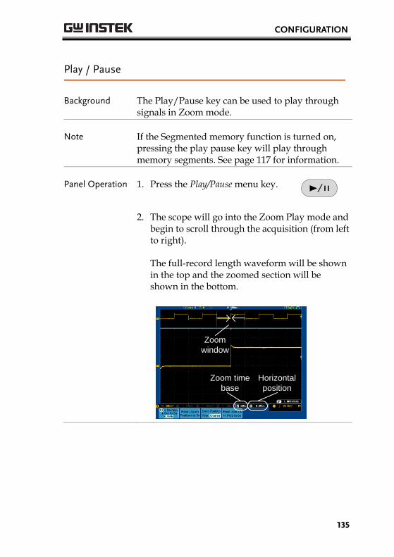
CONFIGURATION
135
Play / Pause
Background The Play/Pause key can be used to play through signals in Zoom mode.
Note If the Segmented memory function is turned on, pressing the play pause key will play through memory segments. See page 117 for information.
Panel Operation 1. Press the Play/Pause menu key.
2. The scope will go into the Zoom Play mode and begin to scroll through the acquisition (from left to right).
The full-record length waveform will be shown in the top and the zoomed section will be shown in the bottom.
Zoom time
base
Horizontal
position
Zoom
window
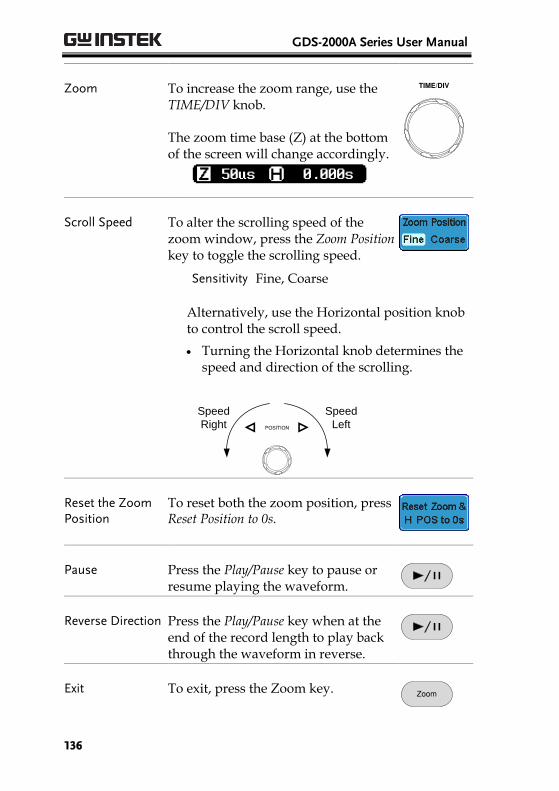
GDS-2000A Series User Manual
136
Zoom To increase the zoom range, use the TIME/DIV knob.
The zoom time base (Z) at the bottom of the screen will change accordingly.
TIME/DIV
Scroll Speed To alter the scrolling speed of the zoom window, press the Zoom Position key to toggle the scrolling speed.
Sensitivity Fine, Coarse
Alternatively, use the Horizontal position knob to control the scroll speed.
Turning the Horizontal knob determines the speed and direction of the scrolling.
POSITION
Speed
Left
Speed
Right
Reset the Zoom Position
To reset both the zoom position, press Reset Position to 0s.
Pause Press the Play/Pause key to pause or resume playing the waveform.
Reverse Direction Press the Play/Pause key when at the end of the record length to play back through the waveform in reverse.
Exit To exit, press the Zoom key. Zoom
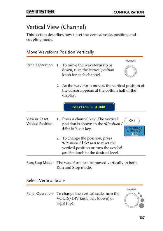
CONFIGURATION
137
Vertical View (Channel) This section describes how to set the vertical scale, position, and coupling mode.
Move Waveform Position Vertically
Panel Operation 1. To move the waveform up or down, turn the vertical position knob for each channel.
POSITION
2. As the waveform moves, the vertical position of the cursor appears at the bottom half of the display.
View or Reset Vertical Position
1. Press a channel key. The vertical position is shown in the Position /
Set to 0 soft key.
2. To change the position, press Position / Set to 0 to reset the
vertical position or turn the vertical position knob to the desired level.
CH1
Run/Stop Mode The waveform can be moved vertically in both Run and Stop mode.
Select Vertical Scale
Panel Operation To change the vertical scale, turn the VOLTS/DIV knob; left (down) or right (up).
VOLTS/DIV
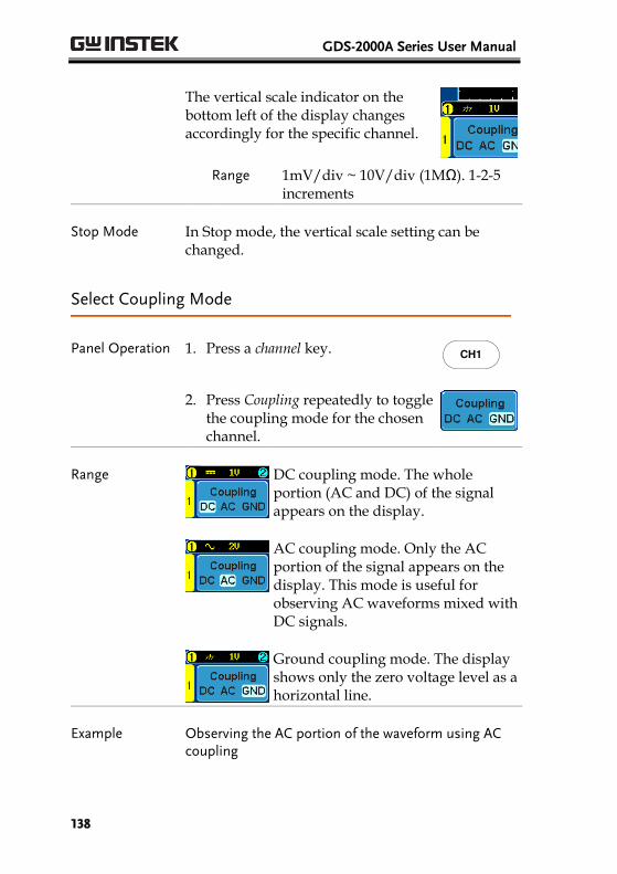
GDS-2000A Series User Manual
138
The vertical scale indicator on the bottom left of the display changes accordingly for the specific channel.
Range 1mV/div ~ 10V/div (1MΩ). 1-2-5 increments
Stop Mode In Stop mode, the vertical scale setting can be changed.
Select Coupling Mode
Panel Operation 1. Press a channel key. CH1
2. Press Coupling repeatedly to toggle the coupling mode for the chosen channel.
Range
DC coupling mode. The whole portion (AC and DC) of the signal appears on the display.
AC coupling mode. Only the AC portion of the signal appears on the display. This mode is useful for observing AC waveforms mixed with DC signals.
Ground coupling mode. The display shows only the zero voltage level as a horizontal line.
Example Observing the AC portion of the waveform using AC coupling
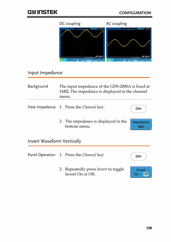
CONFIGURATION
139
DC coupling
AC coupling
Input Impedance
Background The input impedance of the GDS-2000A is fixed at 1MΩ. The impedance is displayed in the channel menu.
View Impedance 1. Press the Channel key. CH1
2. The impedance is displayed in the bottom menu.
Invert Waveform Vertically
Panel Operation 1. Press the Channel key. CH1
2. Repeatedly press Invert to toggle Invert On or Off.
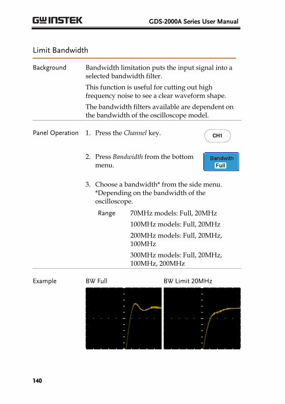
GDS-2000A Series User Manual
140
Limit Bandwidth
Background Bandwidth limitation puts the input signal into a selected bandwidth filter.
This function is useful for cutting out high frequency noise to see a clear waveform shape.
The bandwidth filters available are dependent on the bandwidth of the oscilloscope model.
Panel Operation 1. Press the Channel key. CH1
2. Press Bandwidth from the bottom menu.
3. Choose a bandwidth* from the side menu. *Depending on the bandwidth of the oscilloscope.
Range 70MHz models: Full, 20MHz
100MHz models: Full, 20MHz
200MHz models: Full, 20MHz, 100MHz
300MHz models: Full, 20MHz, 100MHz, 200MHz
Example BW Full
BW Limit 20MHz
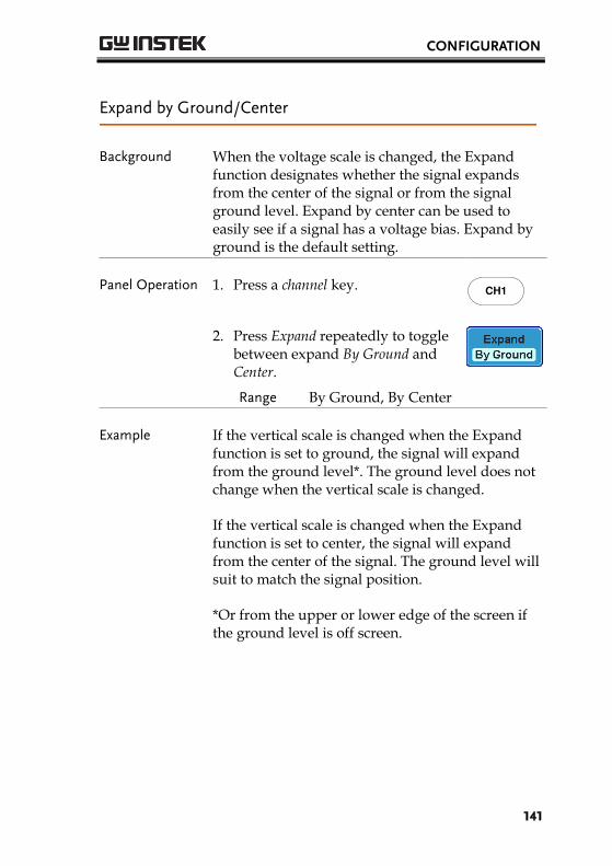
CONFIGURATION
141
Expand by Ground/Center
Background When the voltage scale is changed, the Expand function designates whether the signal expands from the center of the signal or from the signal ground level. Expand by center can be used to easily see if a signal has a voltage bias. Expand by ground is the default setting.
Panel Operation 1. Press a channel key. CH1
2. Press Expand repeatedly to toggle between expand By Ground and Center.
Range By Ground, By Center
Example If the vertical scale is changed when the Expand function is set to ground, the signal will expand from the ground level*. The ground level does not change when the vertical scale is changed.
If the vertical scale is changed when the Expand function is set to center, the signal will expand from the center of the signal. The ground level will suit to match the signal position.
*Or from the upper or lower edge of the screen if the ground level is off screen.
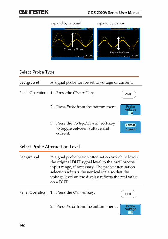
GDS-2000A Series User Manual
142
Expand by Ground
Expand by Ground
Expand by Center
Expand by Center
Select Probe Type
Background A signal probe can be set to voltage or current.
Panel Operation 1. Press the Channel key. CH1
2. Press Probe from the bottom menu.
3. Press the Voltage/Current soft-key to toggle between voltage and current.
Select Probe Attenuation Level
Background A signal probe has an attenuation switch to lower the original DUT signal level to the oscilloscope input range, if necessary. The probe attenuation selection adjusts the vertical scale so that the voltage level on the display reflects the real value on a DUT.
Panel Operation 1. Press the Channel key. CH1
2. Press Probe from the bottom menu.
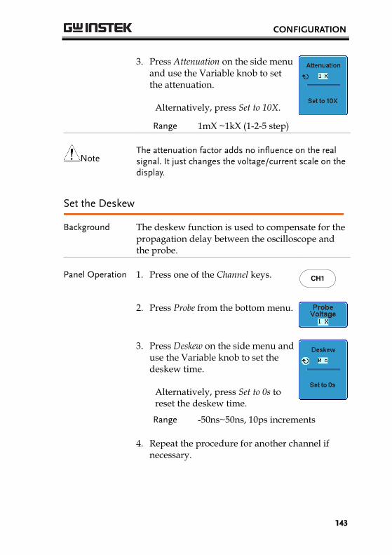
CONFIGURATION
143
3. Press Attenuation on the side menu and use the Variable knob to set the attenuation.
Alternatively, press Set to 10X.
Range 1mX ~1kX (1-2-5 step)
Note The attenuation factor adds no influence on the real signal. It just changes the voltage/current scale on the display.
Set the Deskew
Background The deskew function is used to compensate for the propagation delay between the oscilloscope and the probe.
Panel Operation 1. Press one of the Channel keys. CH1
2. Press Probe from the bottom menu.
3. Press Deskew on the side menu and use the Variable knob to set the deskew time.
Alternatively, press Set to 0s to reset the deskew time.
Range -50ns~50ns, 10ps increments
4. Repeat the procedure for another channel if necessary.
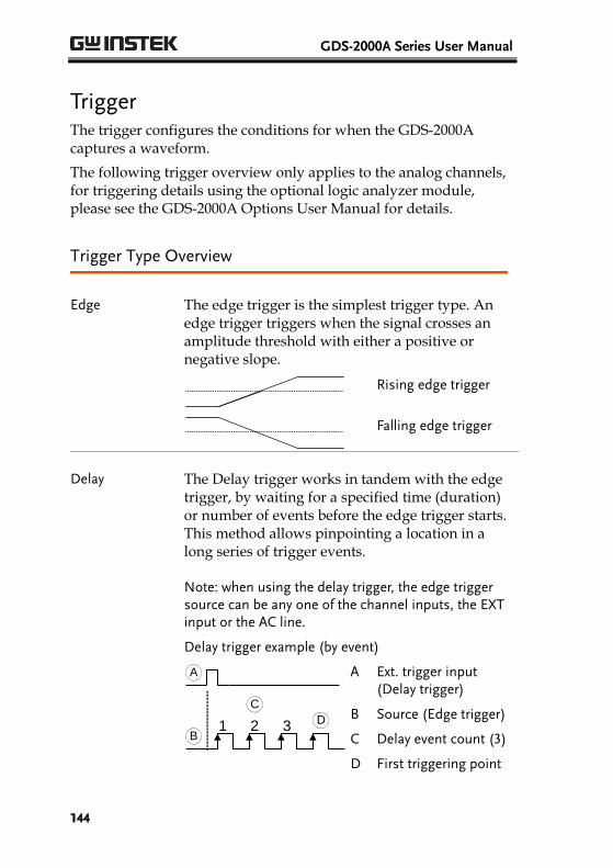
GDS-2000A Series User Manual
144
Trigger The trigger configures the conditions for when the GDS-2000A captures a waveform.
The following trigger overview only applies to the analog channels, for triggering details using the optional logic analyzer module, please see the GDS-2000A Options User Manual for details.
Trigger Type Overview
Edge The edge trigger is the simplest trigger type. An edge trigger triggers when the signal crosses an amplitude threshold with either a positive or negative slope.
Rising edge trigger
Falling edge trigger
Delay The Delay trigger works in tandem with the edge trigger, by waiting for a specified time (duration) or number of events before the edge trigger starts. This method allows pinpointing a location in a long series of trigger events.
Note: when using the delay trigger, the edge trigger source can be any one of the channel inputs, the EXT input or the AC line.
Delay trigger example (by event)
1 2 3
A
B
C
D
A Ext. trigger input (Delay trigger)
B Source (Edge trigger)
C Delay event count (3)
D First triggering point
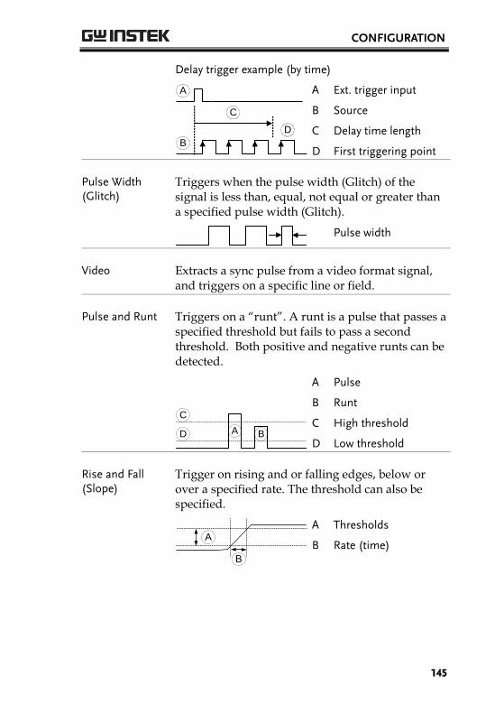
CONFIGURATION
145
Delay trigger example (by time)
A
B
C
D
A Ext. trigger input
B Source
C Delay time length
D First triggering point
Pulse Width (Glitch)
Triggers when the pulse width (Glitch) of the signal is less than, equal, not equal or greater than a specified pulse width (Glitch).
Pulse width
Video Extracts a sync pulse from a video format signal, and triggers on a specific line or field.
Pulse and Runt Triggers on a “runt”. A runt is a pulse that passes a specified threshold but fails to pass a second threshold. Both positive and negative runts can be detected.
A B
C
D
A Pulse
B Runt
C High threshold
D Low threshold
Rise and Fall (Slope)
Trigger on rising and or falling edges, below or over a specified rate. The threshold can also be specified.
B
A
A Thresholds
B Rate (time)
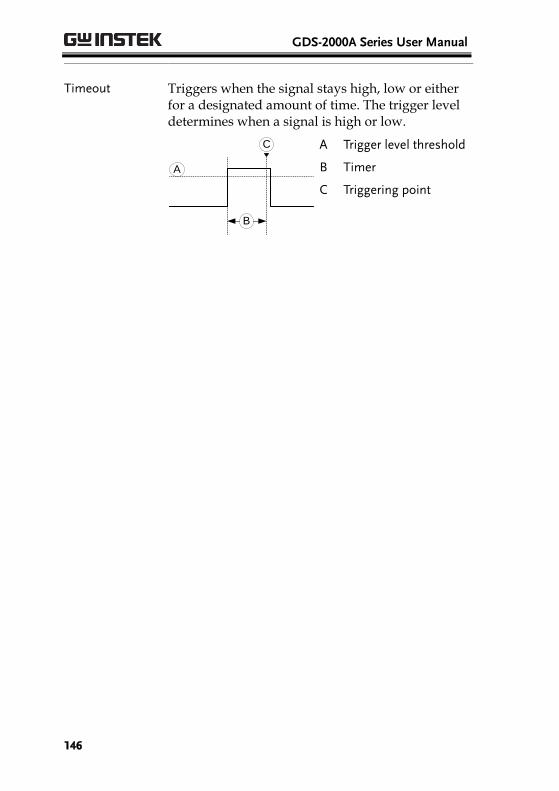
GDS-2000A Series User Manual
146
Timeout Triggers when the signal stays high, low or either for a designated amount of time. The trigger level determines when a signal is high or low.
A
B
C
A Trigger level threshold
B Timer
C Triggering point
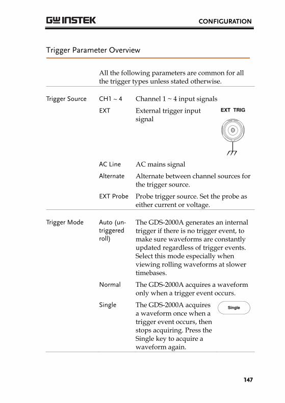
CONFIGURATION
147
Trigger Parameter Overview
All the following parameters are common for all the trigger types unless stated otherwise.
Trigger Source
CH1 ~ 4 Channel 1 ~ 4 input signals
EXT External trigger input signal
EXT TRIG
AC Line AC mains signal
Alternate Alternate between channel sources for the trigger source.
EXT Probe Probe trigger source. Set the probe as either current or voltage.
Trigger Mode
Auto (un-triggered roll)
The GDS-2000A generates an internal trigger if there is no trigger event, to make sure waveforms are constantly updated regardless of trigger events. Select this mode especially when viewing rolling waveforms at slower timebases.
Normal The GDS-2000A acquires a waveform only when a trigger event occurs.
Single The GDS-2000A acquires a waveform once when a trigger event occurs, then stops acquiring. Press the Single key to acquire a waveform again.
Single
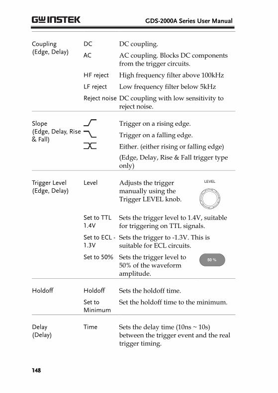
GDS-2000A Series User Manual
148
Coupling (Edge, Delay)
DC DC coupling.
AC AC coupling. Blocks DC components from the trigger circuits.
HF reject High frequency filter above 100kHz
LF reject Low frequency filter below 5kHz
Reject noise DC coupling with low sensitivity to reject noise.
Slope (Edge, Delay, Rise & Fall)
Trigger on a rising edge.
Trigger on a falling edge.
Either. (either rising or falling edge)
(Edge, Delay, Rise & Fall trigger type only)
Trigger Level (Edge, Delay)
Level Adjusts the trigger manually using the Trigger LEVEL knob.
LEVEL
Set to TTL 1.4V
Sets the trigger level to 1.4V, suitable for triggering on TTL signals.
Set to ECL -1.3V
Sets the trigger to -1.3V. This is suitable for ECL circuits.
Set to 50% Sets the trigger level to 50% of the waveform amplitude.
50 %
Holdoff Holdoff Sets the holdoff time.
Set to Minimum
Set the holdoff time to the minimum.
Delay (Delay)
Time Sets the delay time (10ns ~ 10s) between the trigger event and the real trigger timing.
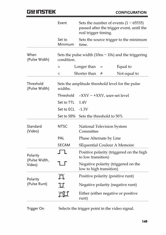
CONFIGURATION
149
Event Sets the number of events (1 ~ 65535) passed after the trigger event, until the real trigger timing.
Set to Minimum
Sets the source trigger to the minimum time.
When (Pulse Width)
Sets the pulse width (10ns ~ 10s) and the triggering condition.
> Longer than = Equal to
< Shorter than ≠ Not equal to
Threshold (Pulse Width)
Sets the amplitude threshold level for the pulse widths.
Threshold –XXV ~ +XXV, user-set level
Set to TTL 1.4V
Set to ECL -1.3V
Set to 50% Sets the threshold to 50%
Standard (Video)
NTSC National Television System Committee
PAL Phase Alternate by Line
SECAM SEquential Couleur A Memoire
Polarity (Pulse Width, Video)
Positive polarity (triggered on the high to low transition)
Negative polarity (triggered on the low to high transition)
Polarity (Pulse Runt)
Positive polarity (positive runt)
Negative polarity (negative runt)
Either (either negative or positive runt)
Trigger On Selects the trigger point in the video signal.
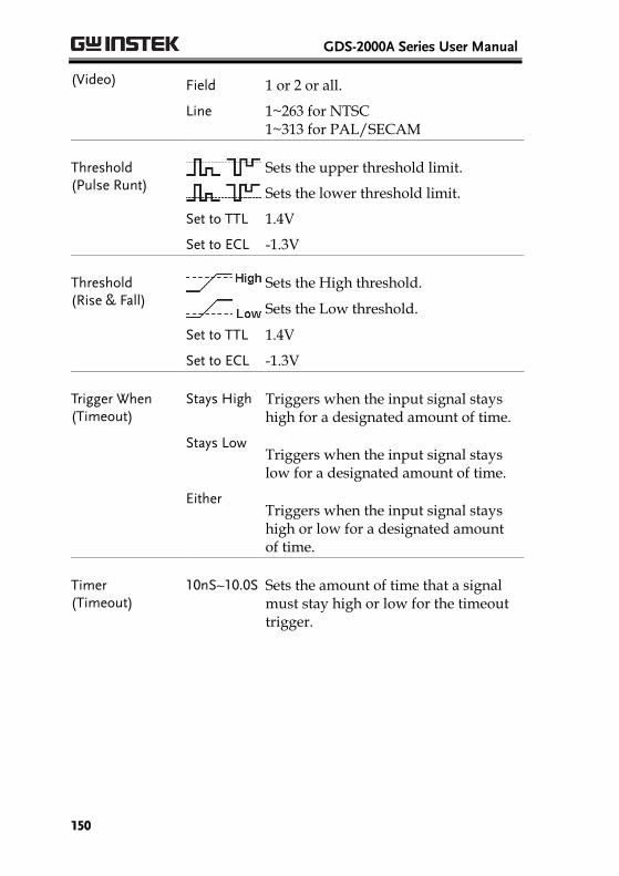
GDS-2000A Series User Manual
150
(Video) Field 1 or 2 or all.
Line 1~263 for NTSC 1~313 for PAL/SECAM
Threshold (Pulse Runt)
Sets the upper threshold limit.
Sets the lower threshold limit.
Set to TTL 1.4V
Set to ECL -1.3V
Threshold (Rise & Fall)
Sets the High threshold.
Sets the Low threshold.
Set to TTL 1.4V
Set to ECL -1.3V
Trigger When (Timeout)
Stays High Triggers when the input signal stays high for a designated amount of time.
Stays Low Triggers when the input signal stays low for a designated amount of time.
Either Triggers when the input signal stays high or low for a designated amount of time.
Timer (Timeout)
10nS~10.0S Sets the amount of time that a signal must stay high or low for the timeout trigger.
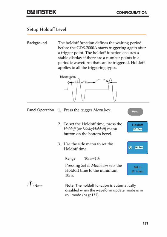
CONFIGURATION
151
Setup Holdoff Level
Background The holdoff function defines the waiting period before the GDS-2000A starts triggering again after a trigger point. The holdoff function ensures a stable display if there are a number points in a periodic waveform that can be triggered. Holdoff applies to all the triggering types.
Holdoff time
Trigger point
Panel Operation 1. Press the trigger Menu key. Menu
2. To set the Holdoff time, press the Holdoff (or Mode/Holdoff) menu button on the bottom bezel.
3. Use the side menu to set the Holdoff time.
Range 10ns~10s
Pressing Set to Minimum sets the Holdoff time to the minimum, 10ns.
Note
Note: The holdoff function is automatically disabled when the waveform update mode is in roll mode (page132).
GDS-2000A Series User Manual
152
Setup Trigger Mode
Background The trigger mode can be set to Normal or Auto (untriggered roll). The triggering mode applies to all the trigger types. See page 132.
Panel Operation 1. Press the Trigger menu key. Menu
2. Press Mode from the bottom menu to change the triggering mode.
3. Use the side panel to select Auto or Normal triggering modes.
Range Auto, Normal
Using the Edge Trigger
Panel Operation 1. Press the Trigger menu key. Menu
2. Press Type from the lower bezel menu.
3. Select Edge from the side menu. The edge trigger indicator appears at the bottom of the display.
From left: trigger source, slope, trigger level, coupling
4. Press Source to change the trigger source.
CONFIGURATION
153
5. Use the side menu to select the trigger source type.
Range Channel 1 ~ 4 (Alternate On/Off), EXT (Ext Probe: Volt/Current, Attenuation: 1mX~1kX ), AC Line
6. Press Coupling from the bottom bezel menu to select the trigger coupling or frequency filter settings.
7. Choose the coupling from the side menu.
Range DC, AC
8. Press Reject to toggle the rejection filter from the side menu.
Range HF Reject, LF Reject, Off
9. Toggle Noise Rejection On or Off from the side menu.
Range On, Off
10. From the bottom menu press Slope to toggle the slope type.
Range Rising edge, falling edge, either
11. To set the external trigger level, select Level from the bottom bezel menu.
GDS-2000A Series User Manual
154
12. Set the external trigger level using the side menu.
Range 00.0V~ 5 screen divisions
Set to TTL 1.4V
Set to ECL -1.3V
Set to 50%
Using Advanced Delay Trigger
Background The EXT trigger source is always used as the delay triggering source.
Panel Operation 1. Press the trigger Menu key. Menu
2. Press Type from the lower bezel menu.
3. Select Delay from the side menu. The delay + edge trigger indicator appears at the bottom of the display.
From left: delay trigger, delay source (external), delay coupling + edge source, edge slope, edge trigger level
4. To set the delay press Delay from the bottom bezel.
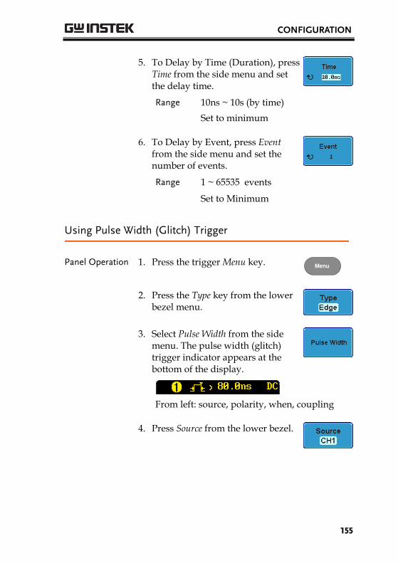
CONFIGURATION
155
5. To Delay by Time (Duration), press Time from the side menu and set the delay time.
Range 10ns ~ 10s (by time)
Set to minimum
6. To Delay by Event, press Event from the side menu and set the number of events.
Range 1 ~ 65535 events
Set to Minimum
Using Pulse Width (Glitch) Trigger
Panel Operation 1. Press the trigger Menu key. Menu
2. Press the Type key from the lower bezel menu.
3. Select Pulse Width from the side menu. The pulse width (glitch) trigger indicator appears at the bottom of the display.
From left: source, polarity, when, coupling
4. Press Source from the lower bezel.
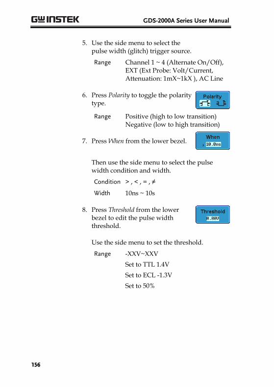
GDS-2000A Series User Manual
156
5. Use the side menu to select the pulse width (glitch) trigger source.
Range Channel 1 ~ 4 (Alternate On/Off), EXT (Ext Probe: Volt/Current, Attenuation: 1mX~1kX ), AC Line
6. Press Polarity to toggle the polarity type.
Range Positive (high to low transition) Negative (low to high transition)
7. Press When from the lower bezel.
Then use the side menu to select the pulse width condition and width.
Condition > , < , = , ≠
Width 10ns ~ 10s
8. Press Threshold from the lower bezel to edit the pulse width threshold.
Use the side menu to set the threshold.
Range -XXV~XXV
Set to TTL 1.4V
Set to ECL -1.3V
Set to 50%
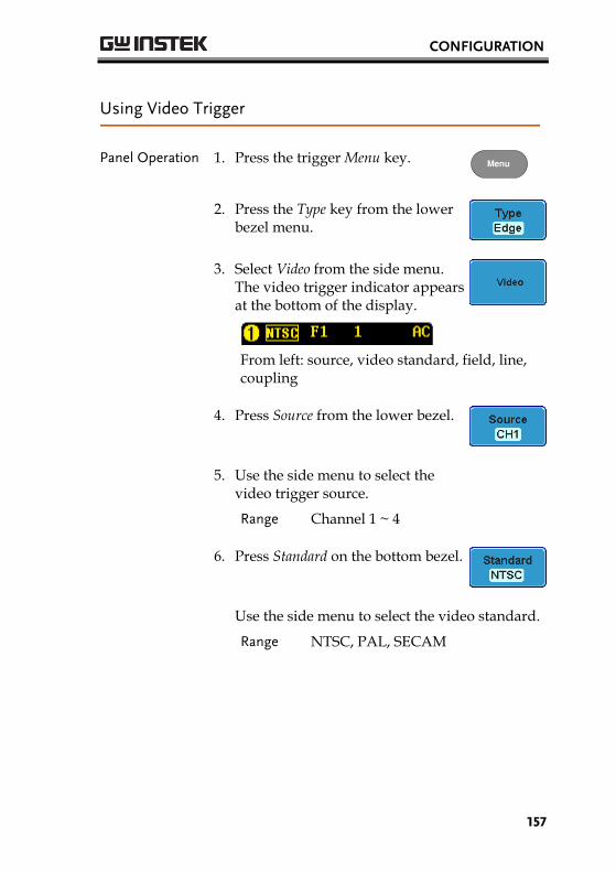
CONFIGURATION
157
Using Video Trigger
Panel Operation 1. Press the trigger Menu key. Menu
2. Press the Type key from the lower bezel menu.
3. Select Video from the side menu. The video trigger indicator appears at the bottom of the display.
From left: source, video standard, field, line, coupling
4. Press Source from the lower bezel.
5. Use the side menu to select the video trigger source.
Range Channel 1 ~ 4
6. Press Standard on the bottom bezel.
Use the side menu to select the video standard.
Range NTSC, PAL, SECAM
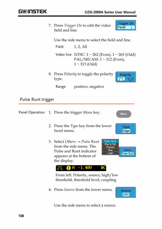
GDS-2000A Series User Manual
158
7. Press Trigger On to edit the video field and line.
Use the side menu to select the field and line.
Field 1, 2, All
Video line NTSC: 1 ~ 262 (Even), 1 ~ 263 (Odd) PAL/SECAM: 1 ~ 312 (Even), 1 ~ 313 (Odd)
8. Press Polarity to toggle the polarity type.
Range positive, negative
Pulse Runt trigger
Panel Operation 1. Press the trigger Menu key. Menu
2. Press the Type key from the lower bezel menu.
3. Select Others → Pulse Runt from the side menu. The Pulse and Runt indicator appears at the bottom of the display.
From left: Polarity, source, high/low threshold, threshold level, coupling
4. Press Source from the lower menu.
Use the side menu to select a source.
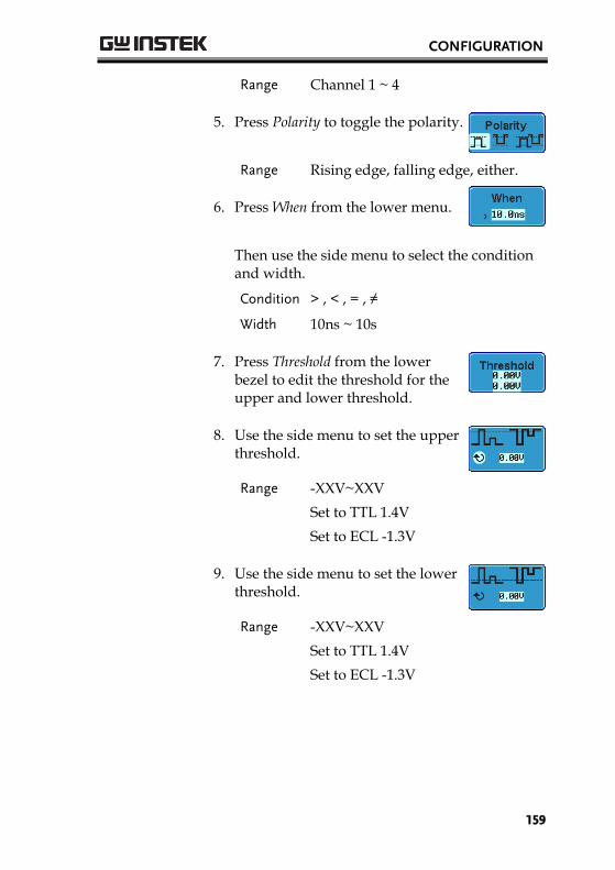
CONFIGURATION
159
Range Channel 1 ~ 4
5. Press Polarity to toggle the polarity.
Range Rising edge, falling edge, either.
6. Press When from the lower menu.
Then use the side menu to select the condition and width.
Condition > , < , = , ≠
Width 10ns ~ 10s
7. Press Threshold from the lower bezel to edit the threshold for the upper and lower threshold.
8. Use the side menu to set the upper threshold.
Range -XXV~XXV
Set to TTL 1.4V
Set to ECL -1.3V
9. Use the side menu to set the lower threshold.
Range -XXV~XXV
Set to TTL 1.4V
Set to ECL -1.3V
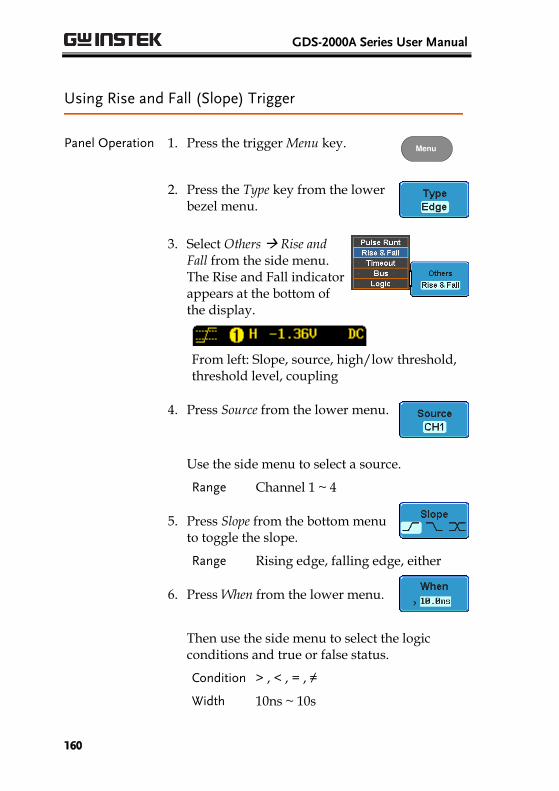
GDS-2000A Series User Manual
160
Using Rise and Fall (Slope) Trigger
Panel Operation 1. Press the trigger Menu key. Menu
2. Press the Type key from the lower bezel menu.
3. Select Others Rise and Fall from the side menu. The Rise and Fall indicator appears at the bottom of the display.
From left: Slope, source, high/low threshold, threshold level, coupling
4. Press Source from the lower menu.
Use the side menu to select a source.
Range Channel 1 ~ 4
5. Press Slope from the bottom menu to toggle the slope.
Range Rising edge, falling edge, either
6. Press When from the lower menu.
Then use the side menu to select the logic conditions and true or false status.
Condition > , < , = , ≠
Width 10ns ~ 10s
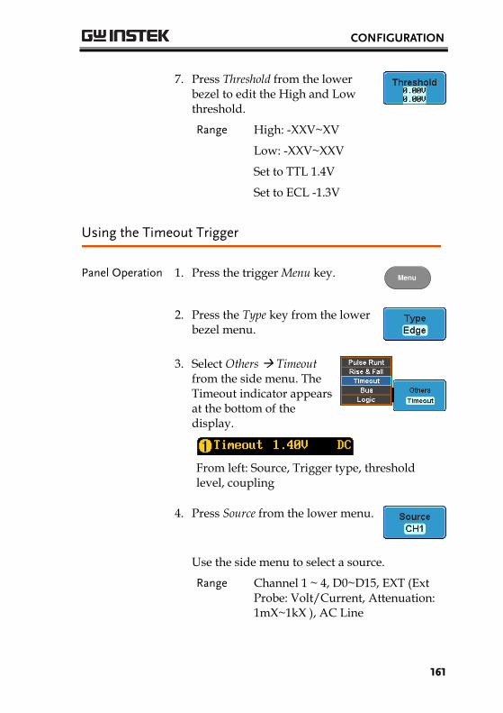
CONFIGURATION
161
7. Press Threshold from the lower bezel to edit the High and Low threshold.
Range High: -XXV~XV
Low: -XXV~XXV
Set to TTL 1.4V
Set to ECL -1.3V
Using the Timeout Trigger
Panel Operation 1. Press the trigger Menu key. Menu
2. Press the Type key from the lower bezel menu.
3. Select Others Timeout from the side menu. The Timeout indicator appears at the bottom of the display.
From left: Source, Trigger type, threshold level, coupling
4. Press Source from the lower menu.
Use the side menu to select a source.
Range Channel 1 ~ 4, D0~D15, EXT (Ext Probe: Volt/Current, Attenuation: 1mX~1kX ), AC Line
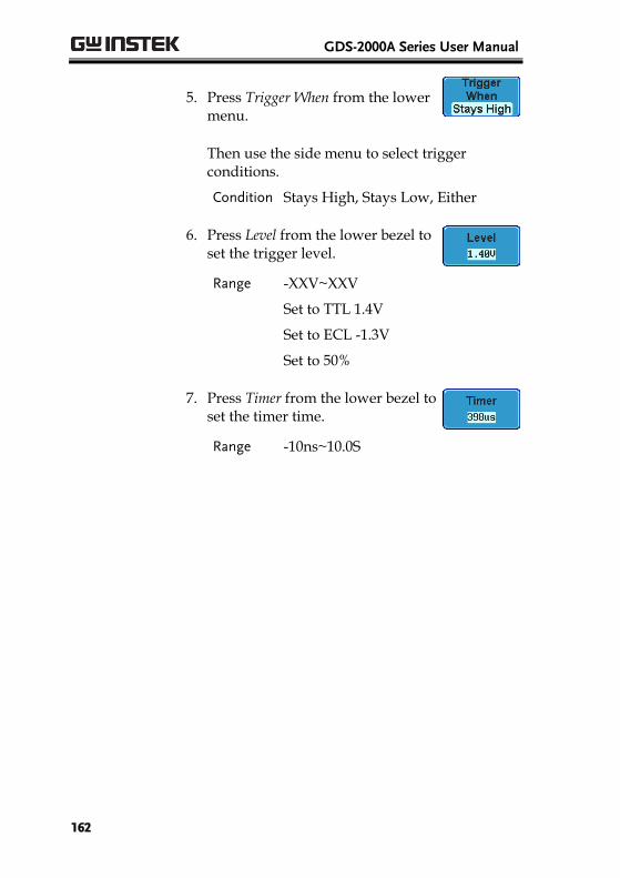
GDS-2000A Series User Manual
162
5. Press Trigger When from the lower menu.
Then use the side menu to select trigger conditions.
Condition Stays High, Stays Low, Either
6. Press Level from the lower bezel to set the trigger level.
Range -XXV~XXV
Set to TTL 1.4V
Set to ECL -1.3V
Set to 50%
7. Press Timer from the lower bezel to set the timer time.
Range -10ns~10.0S
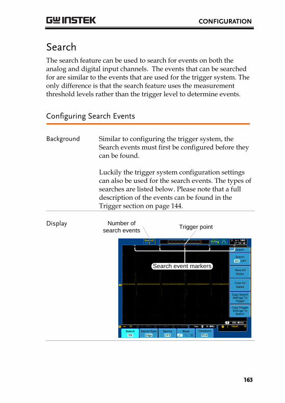
CONFIGURATION
163
Search The search feature can be used to search for events on both the analog and digital input channels. The events that can be searched for are similar to the events that are used for the trigger system. The only difference is that the search feature uses the measurement threshold levels rather than the trigger level to determine events.
Configuring Search Events
Background Similar to configuring the trigger system, the Search events must first be configured before they can be found.
Luckily the trigger system configuration settings can also be used for the search events. The types of searches are listed below. Please note that a full description of the events can be found in the Trigger section on page 144.
Display Number of
search events
Search event markers
Trigger point
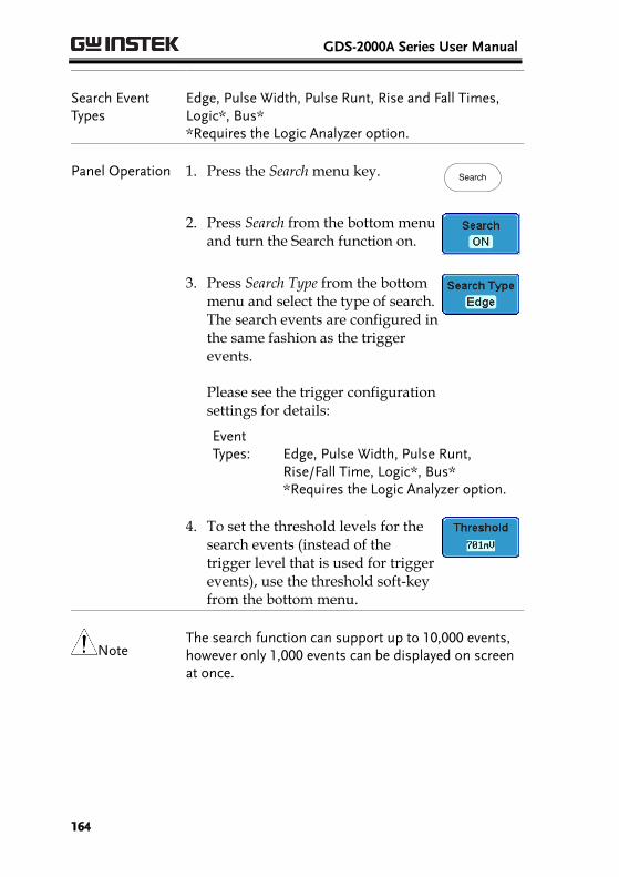
GDS-2000A Series User Manual
164
Search Event Types
Edge, Pulse Width, Pulse Runt, Rise and Fall Times, Logic*, Bus* *Requires the Logic Analyzer option.
Panel Operation 1. Press the Search menu key. Search
2. Press Search from the bottom menu and turn the Search function on.
3. Press Search Type from the bottom menu and select the type of search. The search events are configured in the same fashion as the trigger events.
Please see the trigger configuration settings for details:
Event Types:
Edge, Pulse Width, Pulse Runt, Rise/Fall Time, Logic*, Bus* *Requires the Logic Analyzer option.
4. To set the threshold levels for the search events (instead of the trigger level that is used for trigger events), use the threshold soft-key from the bottom menu.
Note The search function can support up to 10,000 events, however only 1,000 events can be displayed on screen at once.
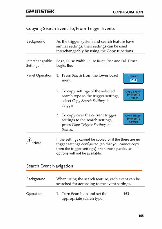
CONFIGURATION
165
Copying Search Event To/From Trigger Events
Background As the trigger system and search feature have similar settings, their settings can be used interchangeably by using the Copy functions.
Interchangeable Settings
Edge, Pulse Width, Pulse Runt, Rise and Fall Times, Logic, Bus
Panel Operation 1. Press Search from the lower bezel menu.
2. To copy settings of the selected search type to the trigger settings, select Copy Search Settings to Trigger.
3. To copy over the current trigger settings to the search settings, press Copy Trigger Settings to Search.
Note If the settings cannot be copied or if the there are no trigger settings configured (so that you cannot copy from the trigger settings), then those particular options will not be available.
Search Event Navigation
Background When using the search feature, each event can be searched for according to the event settings.
Operation 1. Turn Search on and set the appropriate search type.
163

GDS-2000A Series User Manual
166
2. Search events are marked by hollow white triangles at the top of the graticule.
3. Use the search arrow keys to move between each search event.
Search events can be navigated in both stop and run mode.
When using the arrow keys to navigate to each event, the “current event” will always be centered on the display.
Save Search Marks
Background The search events can be saved to the graticule display, allowing you to superimpose new search events. Search event are saved over the entire record length, with a maximum of 200 marks.
Save Marks 1. Press Search from the lower bezel menu.
2. Press the Save All Marks soft-key.
3. The search event markers will become solid white triangles to indicate that they have been saved.
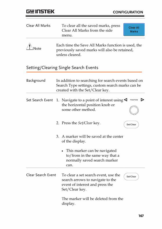
CONFIGURATION
167
Clear All Marks To clear all the saved marks, press Clear All Marks from the side menu.
Note Each time the Save All Marks function is used, the previously saved marks will also be retained, unless cleared.
Setting/Clearing Single Search Events
Background In addition to searching for search events based on Search Type settings, custom search marks can be created with the Set/Clear key.
Set Search Event 1. Navigate to a point of interest using the horizontal position knob or some other method.
POSITION
2. Press the Set/Clear key. Set/Clear
3. A marker will be saved at the center of the display.
This marker can be navigated to/from in the same way that a normally saved search marker can.
Clear Search Event To clear a set search event, use the search arrows to navigate to the event of interest and press the Set/Clear key.
The marker will be deleted from the display.
Set/Clear
GDS-2000A Series User Manual
168
System Info / Language / Clock This section describes how to set the interface, beeper, language, time/date, and probe compensation signal.
Select Menu Language
Parameter The following is a list of the languages available by default. Language selection may differ according to the region.
English Chinese (traditional)
Chinese (simplified) Korean
Japanese Polish
French Spanish
Russian German
Panel Operation 1. Press the Utility key. Utility
2. Select the language from the side menu.
Range* English, Trad. Chinese, Simp. Chinese, Korean, Japanese, Polish, French, Spanish, Russian, German.
*Language selection may differ based on region.
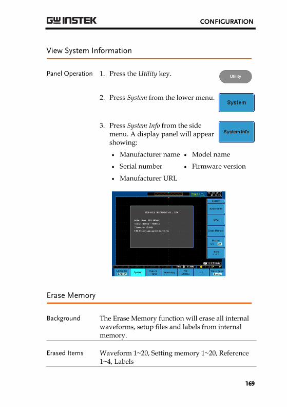
CONFIGURATION
169
View System Information
Panel Operation 1. Press the Utility key. Utility
2. Press System from the lower menu.
3. Press System Info from the side menu. A display panel will appear showing:
Manufacturer name Model name
Serial number Firmware version
Manufacturer URL
Erase Memory
Background The Erase Memory function will erase all internal waveforms, setup files and labels from internal memory.
Erased Items Waveform 1~20, Setting memory 1~20, Reference 1~4, Labels
GDS-2000A Series User Manual
170
Panel Operation 1. Press the Utility key. Utility
2. Press System from the lower menu.
3. Press Erase Memory from the side menu.
A message will prompt you to press Erase Memory again to confirm the process.
4. Press Erase Memory again.
Turn the Buzzer On/Off
Panel Operation 1. Press the Utility key. Utility
2. Press System from the lower menu.
3. Press Buzzer to toggle the buzzer sound on or off.
Set Date and Time
Panel Operation/ Parameter
1. Press the Utility key. Utility
2. Press Date & Time on the lower menu.
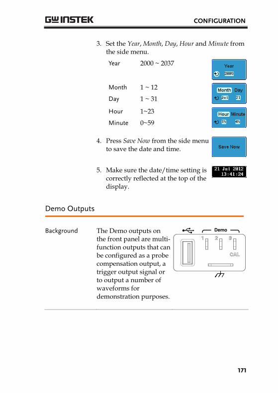
CONFIGURATION
171
3. Set the Year, Month, Day, Hour and Minute from the side menu.
Year 2000 ~ 2037
Month 1 ~ 12
Day 1 ~ 31
Hour 1~23
Minute 0~59
4. Press Save Now from the side menu to save the date and time.
5. Make sure the date/time setting is correctly reflected at the top of the display.
Demo Outputs
Background The Demo outputs on the front panel are multi-function outputs that can be configured as a probe compensation output, a trigger output signal or to output a number of waveforms for demonstration purposes.
Demo
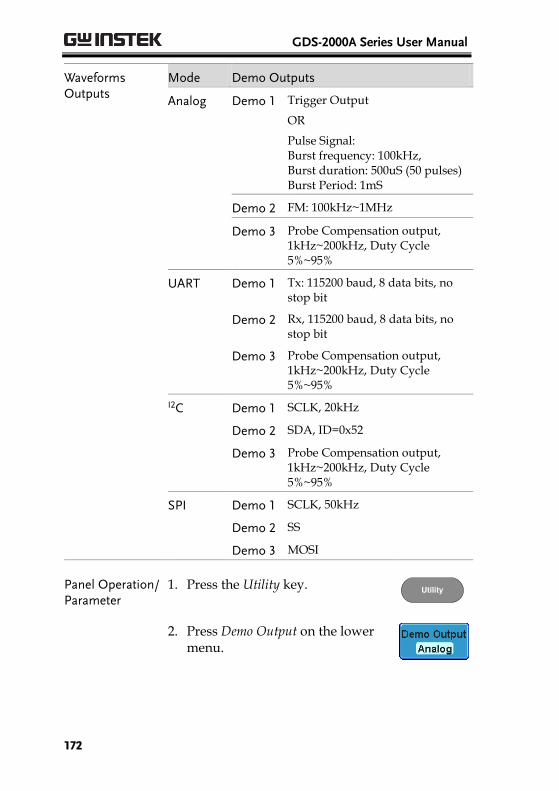
GDS-2000A Series User Manual
172
Waveforms Outputs
Mode Demo Outputs
Analog Demo 1 Trigger Output
OR
Pulse Signal: Burst frequency: 100kHz, Burst duration: 500uS (50 pulses) Burst Period: 1mS
Demo 2 FM: 100kHz~1MHz
Demo 3 Probe Compensation output, 1kHz~200kHz, Duty Cycle 5%~95%
UART Demo 1 Tx: 115200 baud, 8 data bits, no stop bit
Demo 2 Rx, 115200 baud, 8 data bits, no stop bit
Demo 3 Probe Compensation output, 1kHz~200kHz, Duty Cycle 5%~95%
I2C Demo 1 SCLK, 20kHz
Demo 2 SDA, ID=0x52
Demo 3 Probe Compensation output, 1kHz~200kHz, Duty Cycle 5%~95%
SPI Demo 1 SCLK, 50kHz
Demo 2 SS
Demo 3 MOSI
Panel Operation/ Parameter
1. Press the Utility key. Utility
2. Press Demo Output on the lower menu.
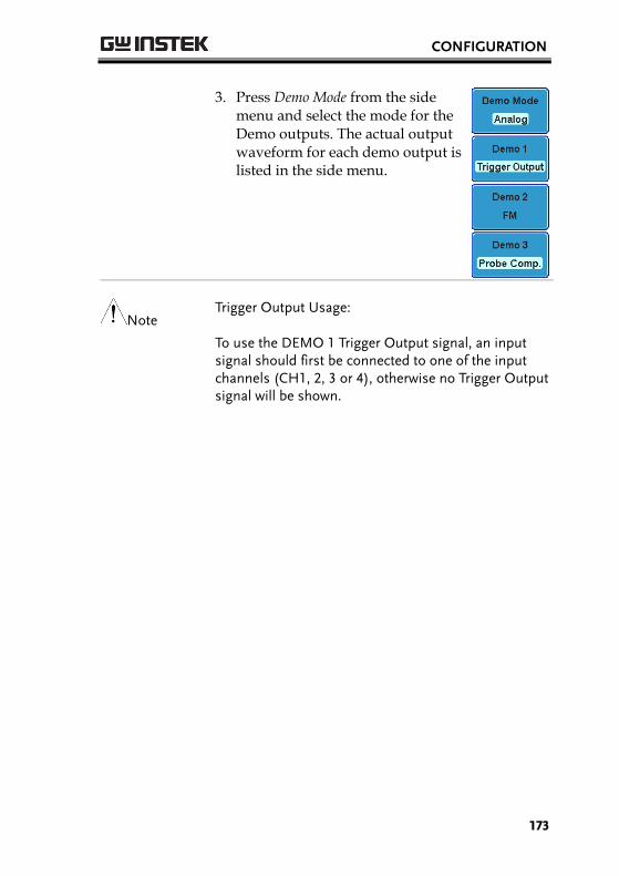
CONFIGURATION
173
3. Press Demo Mode from the side menu and select the mode for the Demo outputs. The actual output waveform for each demo output is listed in the side menu.
Note Trigger Output Usage:
To use the DEMO 1 Trigger Output signal, an input signal should first be connected to one of the input channels (CH1, 2, 3 or 4), otherwise no Trigger Output signal will be shown.
GDS-2000A Series User Manual
174
OPTIONAL SOFTWARE
and APPS.
Applications ................................................................... 175 Overview ............................................................................. 175 Running Applications ........................................................ 175 Uninstalling Applications .................................................. 176 Using Go-NoGo ................................................................ 177
Optional Software .......................................................... 182 Activating Optional Software ........................................... 182 Running Optional Software .............................................. 182 Uninstalling Optional Software ........................................ 183
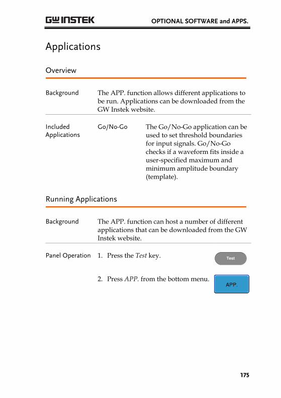
OPTIONAL SOFTWARE and APPS.
175
Applications
Overview
Background The APP. function allows different applications to be run. Applications can be downloaded from the GW Instek website.
Included Applications
Go/No-Go The Go/No-Go application can be used to set threshold boundaries for input signals. Go/No-Go checks if a waveform fits inside a user-specified maximum and minimum amplitude boundary (template).
Running Applications
Background The APP. function can host a number of different applications that can be downloaded from the GW Instek website.
Panel Operation 1. Press the Test key. Test
2. Press APP. from the bottom menu.
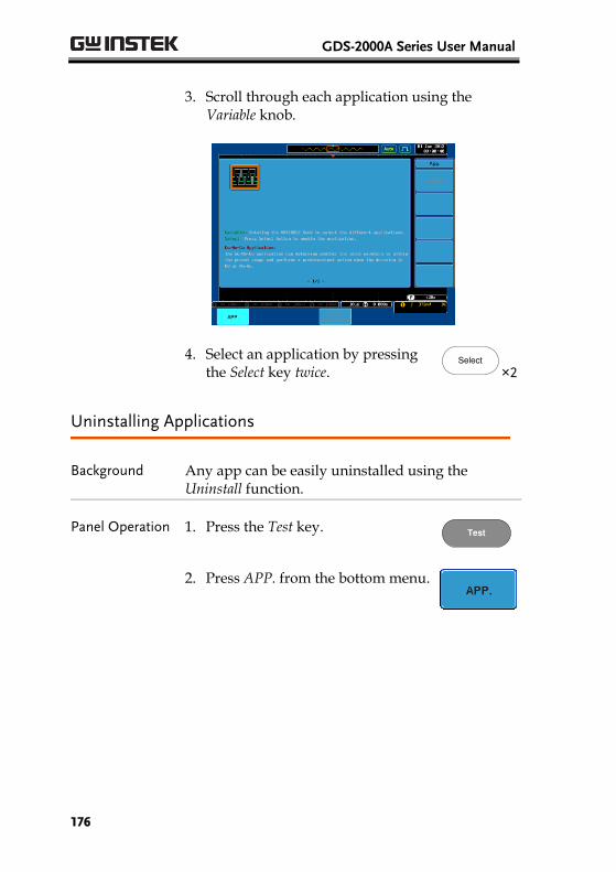
GDS-2000A Series User Manual
176
3. Scroll through each application using the Variable knob.
4. Select an application by pressing the Select key twice.
Select
×2
Uninstalling Applications
Background Any app can be easily uninstalled using the Uninstall function.
Panel Operation 1. Press the Test key. Test
2. Press APP. from the bottom menu.
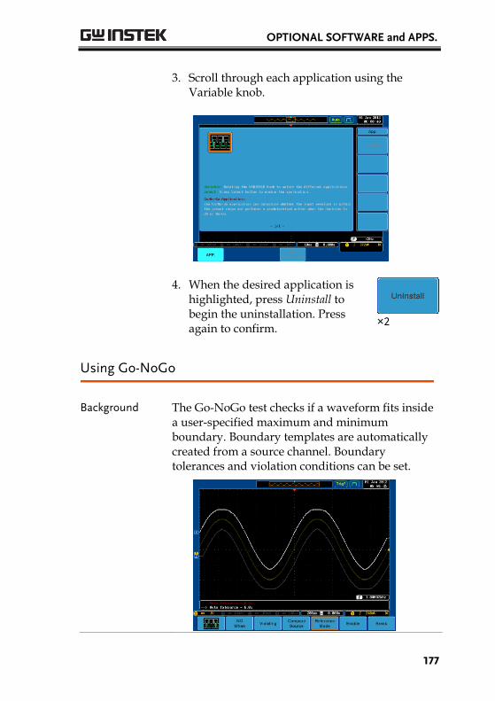
OPTIONAL SOFTWARE and APPS.
177
3. Scroll through each application using the Variable knob.
4. When the desired application is highlighted, press Uninstall to begin the uninstallation. Press again to confirm.
×2
Using Go-NoGo
Background The Go-NoGo test checks if a waveform fits inside a user-specified maximum and minimum boundary. Boundary templates are automatically created from a source channel. Boundary tolerances and violation conditions can be set.
GDS-2000A Series User Manual
178
Choose the Go_NoGo application from the APP. menu. See page 175.
Set Go-NoGo Conditions
Select the Go-NoGo conditions (NG When) and actions when a Go-NoGo condition has been met (Violating).
1. Press NG When from the bottom menu and select the NoGo conditions:
Enters: Sets the NoGo condition to when the input signal stays within the limit boundary.
Exits: Sets the NoGo condition to when the input signal exceeds the limit boundary.
2. Press Go Back to return to the previous menu.
Set Go-NoGo Actions
1. Press Violating to set what action to perform when a signal is violating the Go-NoGo conditions.
The waveform stops when the conditions are violated.
The waveform stops and a beep will be output when the conditions are violated.
Ignore violations and continue to monitor the signal.
Output a beep when a violation occurs, but continue to monitor the signal.
OPTIONAL SOFTWARE and APPS.
179
2. Press Go Back to return to the previous menu.
Set Go-NoGo Source
1. Press Compare Source from the bottom menu to set the Go-NoGo boundary source.
Sets CH1 as the source.
Sets CH2 as the source.
Sets CH3 as the source.
Sets CH4 as the source.
2. Press Go Back to return to the previous menu.
Set Boundary Tolerance
1. To set the Go-NoGo boundary tolerance, press Reference Mode.
Auto Tolerance 2. To set the boundary tolerance as a percentage offset from the source waveform, press Auto Tolerance and use the Variable knob.
VARIABLE
Offset 0.4% ~ 40% (.4% steps)
Maximum and Minimum Position
3. To manually set the template tolerance, press Minimum Position or Maximum Position and use the Variable knob to set the absolute minimum or maximum position.
or

GDS-2000A Series User Manual
180
Range Voltage division range
Save Boundary Template
4. Press Save Operation to save the tolerance boundaries.
5. The Maximum Position tolerance will be saved to reference waveform R1, and the Minimum Position tolerance to R2.
6. Press Go Back to return to the previous menu.
Note It may be necessary to save a reference waveform to R1 and R2 before the tolerance for Maximum and Minimum Position can be created. This can be done by first creating and saving the Auto Tolerance boundary.
Start Go-NoGo Press Enable to start the Go-NoGo test. The Enable button will change to Disable. Pressing Disable will stop the Go-NoGo test and toggle the button back to Enable.
If the Violating setting was set to Stop or Stop Beep, press Enable to restart the test after it has stopped.
Results When Go-NoGo is running, the pass/fail ratio is displayed in the bottom left-hand corner. The first digit represents the number of failed tests, and the right hand digit represents the number of tests.
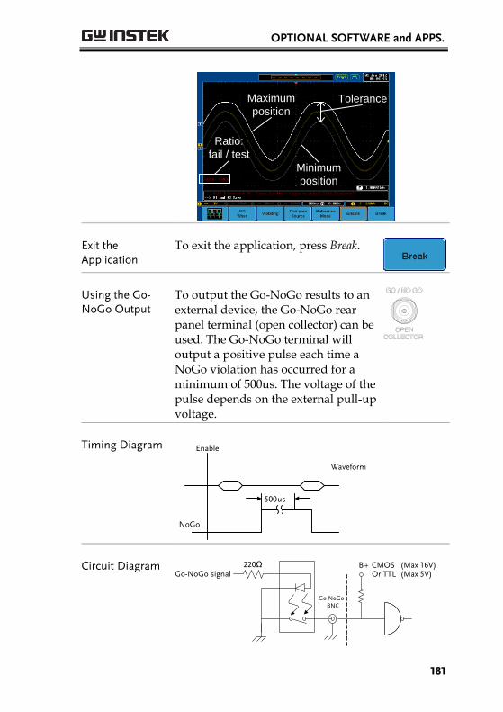
OPTIONAL SOFTWARE and APPS.
181
Ratio:
fail / test
Maximum
position
Minimum
position
Tolerance
Exit the Application
To exit the application, press Break.
Using the Go-NoGo Output
To output the Go-NoGo results to an external device, the Go-NoGo rear panel terminal (open collector) can be used. The Go-NoGo terminal will output a positive pulse each time a NoGo violation has occurred for a minimum of 500us. The voltage of the pulse depends on the external pull-up voltage.
Timing Diagram Enable
NoGo
500 us
Waveform
Circuit Diagram Go-NoGo signal 220 Ω
Go-NoGo BNC
B + CMOS (Max 16V) Or TTL (Max 5V)
GDS-2000A Series User Manual
182
Optional Software
Activating Optional Software
Background The GDS-2000A has optional software packages to expand the functionality of the standard GDS-2000A. An activation key is required to activate any optional software. A different activation key is required for each optional software package.
For the latest files and information regarding the optional software packages, see the GW Instek website: www.gwinstek.com or contact your nearest distributor.
Install Optional Hardware Modules
Please see page 30 for details on how to install optional hardware modules if the option software also requires option hardware modules.
Install Optional Software Modules
Please see page 31 for details on how to install the optional software packages.
Running Optional Software
Background Most of the optional software functions can be accessed via the Option key, located beside the bottom menu keys.
Panel Operation 1. Press the Option key. Option
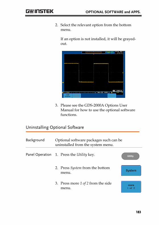
OPTIONAL SOFTWARE and APPS.
183
2. Select the relevant option from the bottom menu.
If an option is not installed, it will be grayed-out.
3. Please see the GDS-2000A Options User Manual for how to use the optional software functions.
Uninstalling Optional Software
Background Optional software packages such can be uninstalled from the system menu.
Panel Operation 1. Press the Utility key. Utility
2. Press System from the bottom menu.
3. Press more 1 of 2 from the side menu.
GDS-2000A Series User Manual
184
4. Press Option Uninstall on the side menu.
5. Select the optional software packages that you wish to uninstall from the side menu.
6. Use the Up and Down arrows on the side menu to select an option to uninstall.
7. Press Uninstall to uninstall the option.
SAVE/RECALL
185
SAVE/RECALL
File Format/Utility .......................................................... 186 Image File Format .............................................................. 186 Waveform File Format ...................................................... 186 Spreadsheet File Format.................................................... 187 Setup File Format ............................................................... 189
Create/Edit Labels .......................................................... 191
Save ............................................................................... 195 File Type/Source/Destination ......................................... 195 Save Image .......................................................................... 196 Save Waveform .................................................................. 198 Save Setup ........................................................................... 200
Recall ............................................................................. 202 File Type/Source/Destination ......................................... 202 Recall Default Panel Setting.............................................. 202 Recall Waveform ................................................................ 205 Recall Setup ......................................................................... 206
Reference Waveforms ..................................................... 209 Recall and Display Reference Waveforms ...................... 209

GDS-2000A Series User Manual
186
File Format/Utility
Image File Format
Format DSxxxx.bmp or DSxxxx.png
Contents The display image is 800 by 600 pixels. The background color can be inverted (Ink saver function). Each image file is saved to the current file path as a bitmap or PNG file.
Waveform File Format
Format DSxxxx.lsf, CH1~CH4.lsf
The LSF file format efficiently stores waveforms. This is the file format used for storing and recalling all waveforms that are be used with the GDS-2000A series.
Waveform Type CH1 ~ 4 Input channel signal
REF Reference waveform
Math Math operation result (page 93)
D0~D15 Digital channels* *For the logic analyzer options only.
Storage Location Wave1 ~ Wave20
Waveform files stored to the internal memory. Stored waveforms can be copied to Ref. 1 ~ 4 to be viewed on the display. (W1 ~ W20 waveforms cannot be directly recalled on the display).
SAVE/RECALL
187
Ref 1~4 Reference waveforms stored in the
internal memory, separate from W1 ~ W20. Reference waveforms (Ref 1 ~ 4) can be displayed directly onto the display with amplitude and frequency information. Ref 1~4 are useful for reference purposes. Other waveforms ( LSF and W1~20) must be recalled to R1~4 before being displayed.
Contents: Waveform Data
The waveform data can be used for detailed analysis. It consists of the horizontal and vertical data used by the waveform.
Spreadsheet File Format
Format DSxxxx.csv (Comma-separated values format, can be opened in spreadsheet applications such as Microsoft Excel).
CSV-formatted files can be stored in either a short-memory format or a long-memory format: Detail CSV, Fast CSV, LM Detail CSV and LM Fast CSV.
Detail CSV will record both the horizontal and vertical sample points of the waveform. All the points are recorded in scientific notation for analog data. CSV data will only record 5000 points of data.
Fast CSV will only record the vertical amplitude of the sample points. Fast CSV also contains data that enables the horizontal data points to be reconstructed, such as trigger position, etc. Fast CSV will only record 5000 points of data. Data is recorded as integers.
LM Detail CSV is similar to CSV but covers the entire long-memory (See page 109 for information on the record length). All points are recorded in scientific notation for analog data.
LM Fast CSV is similar to Fast CSV but covers the
GDS-2000A Series User Manual
188
entire long memory length (See page 109 for information on the record length). All points are recorded as integers.
Note, however, that only fast CSV can be recalled to the internal memory. Detailed CSV, LM Fast CSV and LM Detailed CSV cannot be recalled.
Waveform Type CH1 ~ 4 Input channel signal
Ref1~4 Reference waveform
Math Math operation result (page 93)
D0~D15 Digital channels
All Displayed
All the waveforms on the display.
Contents: Detail CSV & LM Detail CSV
Detail CSV waveform data contains channel information such as vertical and horizontal position of a signal for 5000 points.
The following information is included in Detail CSV, where applicable:
Format (scope type) Memory length
Trigger Level Source
Label Probe ratio
Vertical units Vertical scale
Vertical position Horizontal units
Horizontal scale Horizontal position
Horizontal mode Sampling period
Firmware Time
Mode Vertical data
Horizontal data
Contents: Fast CSV
The following information is included in the Fast CSV waveform files, where applicable:
SAVE/RECALL
189
& LM Fast CSV
Format (scope type)
Memory length
IntpDistance (input trigger distance)
Trigger address
Trigger level Source
Vertical units Vertical units div
Vertical units extend div
Label
Probe type Probe ratio
Vertical scale Vertical position
Horizontal units Horizontal scale
Horizontal position Horizontal mode
SincET mode (sampling mode)
Sampling period
Horizontal old scale Horizontal old position
Firmware Time
Mode Raw vertical waveform data
Setup File Format
Format DSxxxx.set (proprietary format)
The setup file saves or recalls the following settings.
Contents Acquire Mode
Sample rate
Digital Filter
XY
Sample mode
Record Length
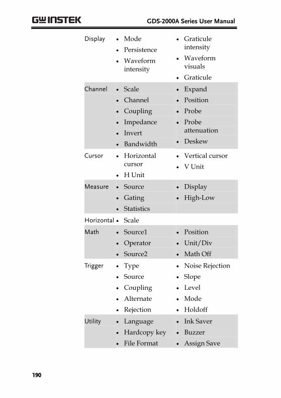
GDS-2000A Series User Manual
190
Display Mode
Persistence
Waveform intensity
Graticule intensity
Waveform visuals
Graticule
Channel Scale
Channel
Coupling
Impedance
Invert
Bandwidth
Expand
Position
Probe
Probe attenuation
Deskew
Cursor Horizontal cursor
H Unit
Vertical cursor
V Unit
Measure Source
Gating
Statistics
Display
High-Low
Horizontal Scale
Math Source1
Operator
Source2
Position
Unit/Div
Math Off
Trigger Type
Source
Coupling
Alternate
Rejection
Noise Rejection
Slope
Level
Mode
Holdoff
Utility Language
Hardcopy key
File Format
Ink Saver
Buzzer
Assign Save

SAVE/RECALL
191
Save/ recall
Image file format
Data file format
Create/Edit Labels
Overview Reference files, Setup files and the analog input channels can have individual file labels set.
For the analog channels and reference waveforms, the file label can be displayed next to the channel/reference indicator.
The file labels are also obviously used to identify reference files, setup files or channels when saving or recalling waveforms and setups.
Example
Label for CH1
Label for Ref 1
In the example above, the file label for channel 1 is displayed next to the channel indicator and is also displayed in the Save Waveform menu. The Ref_1 file label is shown next to the reference indicator.
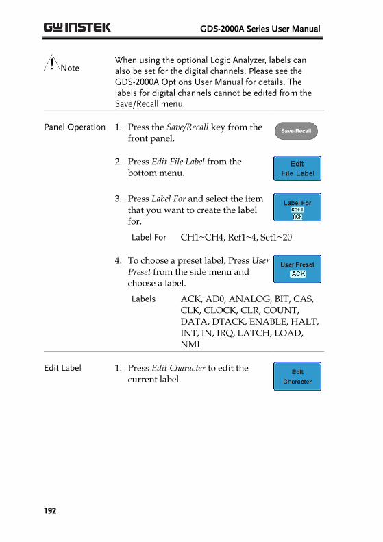
GDS-2000A Series User Manual
192
Note When using the optional Logic Analyzer, labels can also be set for the digital channels. Please see the GDS-2000A Options User Manual for details. The labels for digital channels cannot be edited from the Save/Recall menu.
Panel Operation 1. Press the Save/Recall key from the front panel.
Save/Recall
2. Press Edit File Label from the bottom menu.
3. Press Label For and select the item that you want to create the label for.
Label For CH1~CH4, Ref1~4, Set1~20
4. To choose a preset label, Press User Preset from the side menu and choose a label.
Labels ACK, AD0, ANALOG, BIT, CAS, CLK, CLOCK, CLR, COUNT, DATA, DTACK, ENABLE, HALT, INT, IN, IRQ, LATCH, LOAD, NMI
Edit Label 1. Press Edit Character to edit the current label.
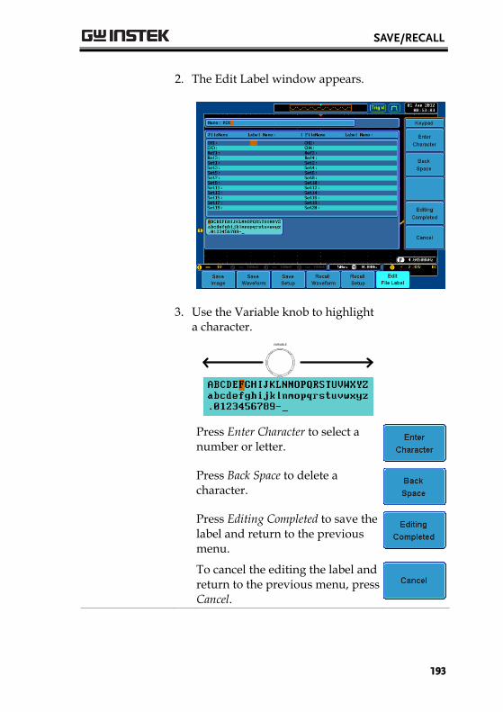
SAVE/RECALL
193
2. The Edit Label window appears.
3. Use the Variable knob to highlight a character.
VARIABLE
Press Enter Character to select a number or letter.
Press Back Space to delete a character.
Press Editing Completed to save the label and return to the previous menu.
To cancel the editing the label and return to the previous menu, press Cancel.

GDS-2000A Series User Manual
194
Display Label To display the currently selected file label on the screen next to its respective indicator, toggle Label Display to On.
Conversely, if you want to remove the currently selected file label from the display, toggle Label Display to Off.
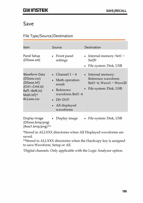
SAVE/RECALL
195
Save
File Type/Source/Destination
Item Source Destination
Panel Setup (DSxxxx.set)
Front panel settings
Internal memory: Set1 ~ Set20
File system: Disk, USB
Waveform Data (DSxxxx.csv) (DSxxxx.lsf) (CH1~CH4.lsf, Ref1~Ref4.lsf, Math.lsf)* ALLxxxx.csv
Channel 1 ~ 4
Math operation result
Reference waveform Ref1~4
D0~D151
All displayed waveforms
Internal memory: Reference waveform Ref1~4, Wave1 ~ Wave20
File system: Disk, USB
Display Image (DSxxxx.bmp/png) (Axxx1.bmp/png)**
Display image File system: Disk, USB
*Stored in ALLXXX directories when All Displayed waveforms are saved. **Stored in ALLXXX directories when the Hardcopy key is assigned to save Waveform, Setup or All.
1Digital channels. Only applicable with the Logic Analyzer option.
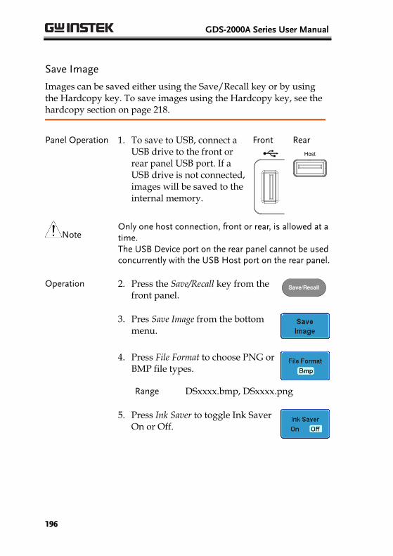
GDS-2000A Series User Manual
196
Save Image
Images can be saved either using the Save/Recall key or by using the Hardcopy key. To save images using the Hardcopy key, see the hardcopy section on page 218.
Panel Operation 1. To save to USB, connect a USB drive to the front or rear panel USB port. If a USB drive is not connected, images will be saved to the internal memory.
Front
Rear
Host
Note Only one host connection, front or rear, is allowed at a time. The USB Device port on the rear panel cannot be used concurrently with the USB Host port on the rear panel.
Operation 2. Press the Save/Recall key from the front panel.
Save/Recall
3. Pres Save Image from the bottom menu.
4. Press File Format to choose PNG or BMP file types.
Range DSxxxx.bmp, DSxxxx.png
5. Press Ink Saver to toggle Ink Saver On or Off.
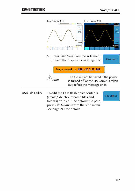
SAVE/RECALL
197
Ink Saver On
Ink Saver Off
6. Press Save Now from the side menu to save the display as an image file.
Note
The file will not be saved if the power is turned off or the USB drive is taken out before the message ends.
USB File Utility To edit the USB flash drive contents (create/ delete/ rename files and folders) or to edit the default file path, press File Utilities from the side menu. See page 211 for details.
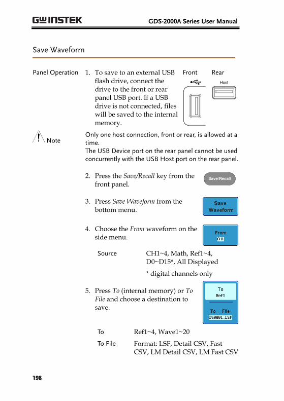
GDS-2000A Series User Manual
198
Save Waveform
Panel Operation 1. To save to an external USB flash drive, connect the drive to the front or rear panel USB port. If a USB drive is not connected, files will be saved to the internal memory.
Front
Rear
Host
Note Only one host connection, front or rear, is allowed at a time. The USB Device port on the rear panel cannot be used concurrently with the USB Host port on the rear panel.
2. Press the Save/Recall key from the front panel.
Save/Recall
3. Press Save Waveform from the bottom menu.
4. Choose the From waveform on the side menu.
Source CH1~4, Math, Ref1~4, D0~D15*, All Displayed
* digital channels only
5. Press To (internal memory) or To File and choose a destination to save.
To Ref1~4, Wave1~20
To File Format: LSF, Detail CSV, Fast CSV, LM Detail CSV, LM Fast CSV
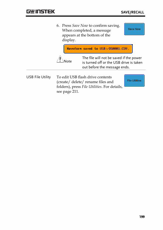
SAVE/RECALL
199
6. Press Save Now to confirm saving. When completed, a message appears at the bottom of the display.
Note
The file will not be saved if the power is turned off or the USB drive is taken out before the message ends.
USB File Utility To edit USB flash drive contents (create/ delete/ rename files and folders), press File Utilities. For details, see page 211.
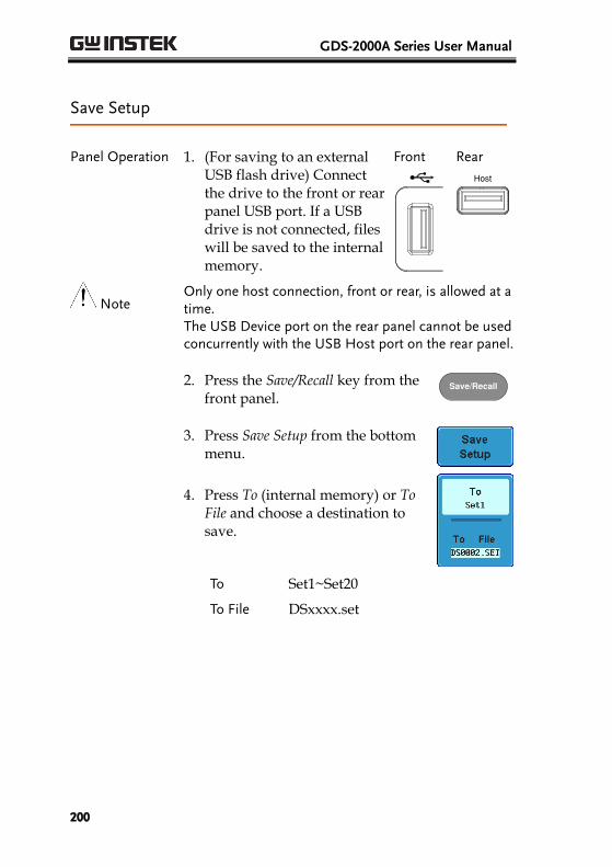
GDS-2000A Series User Manual
200
Save Setup
Panel Operation 1. (For saving to an external USB flash drive) Connect the drive to the front or rear panel USB port. If a USB drive is not connected, files will be saved to the internal memory.
Front
Rear
Host
Note Only one host connection, front or rear, is allowed at a time. The USB Device port on the rear panel cannot be used concurrently with the USB Host port on the rear panel.
2. Press the Save/Recall key from the front panel.
Save/Recall
3. Press Save Setup from the bottom menu.
4. Press To (internal memory) or To File and choose a destination to save.
To Set1~Set20
To File DSxxxx.set
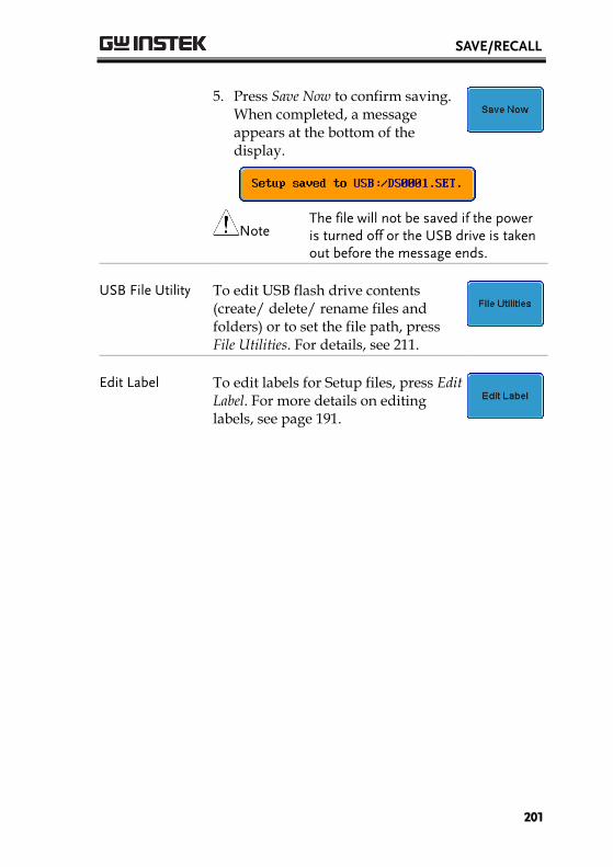
SAVE/RECALL
201
5. Press Save Now to confirm saving. When completed, a message appears at the bottom of the display.
Note
The file will not be saved if the power is turned off or the USB drive is taken out before the message ends.
USB File Utility To edit USB flash drive contents (create/ delete/ rename files and folders) or to set the file path, press File Utilities. For details, see 211.
Edit Label To edit labels for Setup files, press Edit Label. For more details on editing labels, see page 191.

GDS-2000A Series User Manual
202
Recall
File Type/Source/Destination
Item Source Destination
Default Panel Setup
Factory installed setting
Current front panel
Reference Waveform
Internal memory: Ref1~4
Current front panel
Panel Setup (DSxxxx.set)
Internal memory: S1 ~ S20
File system: Disk, USB
Current front panel
Waveform Data (DSxxxx.lsf, DSxxxx.csv**) (CH1~CH4.lsf, Ref1~Ref4.lsf, Math.lsf)*
Internal memory: Wave 1 ~ Wave20
File system: Disk, USB
Reference waveform 1 ~ 4
*Recalled from ALLXXX directories. Note that Allxxxx.csv cannot be recalled to the oscilloscope.
**Detail CSV, LM Detail CSV and LM Fast CSV files cannot be recalled to the oscilloscope.
Recall Default Panel Setting
Panel Operation 1. Press the Default key. Default
2. The screen will update with the default panel settings.

SAVE/RECALL
203
Setting Contents The following is the default (factory) setting contents.
Acquire Mode: Sample XY: OFF
Sample mode: Sinc Sample rate: 2GSPS
Digital filter: Off Record Length: Auto
Display Mode: Vector Persistence: 16ms
Waveform intensity: 50% Graticule intensity: 50%
Waveform visuals: Gray Graticule: full
Channel Scale: 100mV/Div CH1: On
Coupling: DC Impedance: 1MΩ
Invert: Off Bandwidth: full
Expand: By ground Position: 0.00V
Probe: voltage Probe attenuation: 1x
Deskew: 0s
Cursor Horizontal cursor: Off Vertical Cursor: Off
H Unit: S V Unit: Base
Measure Source 1: CH1 Source 2: CH2
Gating: Off Display: Off
High-Low: Auto Statistics: Off
Mean & Std: 2
Horizontal Scale: 10us/Div
Math Source1: CH1 Operator: +
Source2: CH2 Position: 0.00 Div
Unit/Div: 200mV Math Off
Test App: Go-NoGo
Trigger Type: Edge Source: CH1
Coupling: DC Alternate: Off
GDS-2000A Series User Manual
204
Rejection: Off Noise Rejection: Off
Slope: rising Level: 0.00V
Mode: Auto Holdoff: 10.0ns
Utility Language: English Hardcopy key: Save
Ink Saver: Off File Format: BMP
Assign Save To: Image Buzzer: Off
Save / Recall Image file format: Bmp Data file format: LSF
Search Search: Off
Segments Segments: Off
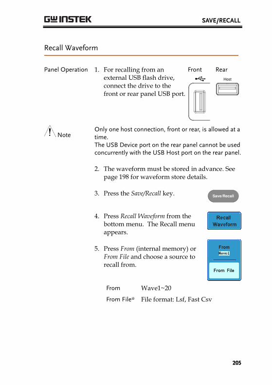
SAVE/RECALL
205
Recall Waveform
Panel Operation 1. For recalling from an external USB flash drive, connect the drive to the front or rear panel USB port.
Front
Rear
Host
Note Only one host connection, front or rear, is allowed at a time. The USB Device port on the rear panel cannot be used concurrently with the USB Host port on the rear panel.
2. The waveform must be stored in advance. See page 198 for waveform store details.
3. Press the Save/Recall key. Save/Recall
4. Press Recall Waveform from the bottom menu. The Recall menu appears.
5. Press From (internal memory) or From File and choose a source to recall from.
From Wave1~20
From File* File format: Lsf, Fast Csv
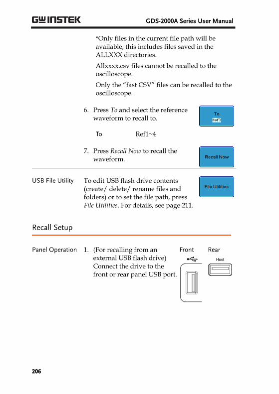
GDS-2000A Series User Manual
206
*Only files in the current file path will be available, this includes files saved in the ALLXXX directories.
Allxxxx.csv files cannot be recalled to the oscilloscope.
Only the “fast CSV” files can be recalled to the oscilloscope.
6. Press To and select the reference waveform to recall to.
To Ref1~4
7. Press Recall Now to recall the
waveform.
USB File Utility To edit USB flash drive contents (create/ delete/ rename files and folders) or to set the file path, press File Utilities. For details, see page 211.
Recall Setup
Panel Operation 1. (For recalling from an external USB flash drive) Connect the drive to the front or rear panel USB port.
Front
Rear
Host
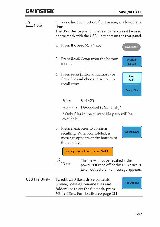
SAVE/RECALL
207
Note Only one host connection, front or rear, is allowed at a time. The USB Device port on the rear panel cannot be used concurrently with the USB Host port on the rear panel.
2. Press the Save/Recall key. Save/Recall
3. Press Recall Setup from the bottom menu.
4. Press From (internal memory) or From File and choose a source to recall from.
From Set1~20
From File DSxxxx.set (USB, Disk)*
* Only files in the current file path will be available.
5. Press Recall Now to confirm recalling. When completed, a message appears at the bottom of the display.
Note
The file will not be recalled if the power is turned off or the USB drive is taken out before the message appears.
USB File Utility To edit USB flash drive contents (create/ delete/ rename files and folders) or to set the file path, press File Utilities. For details, see page 211.

GDS-2000A Series User Manual
208
Edit Label To edit labels for Setup files, press Edit label. For more details on editing labels, see page 191.
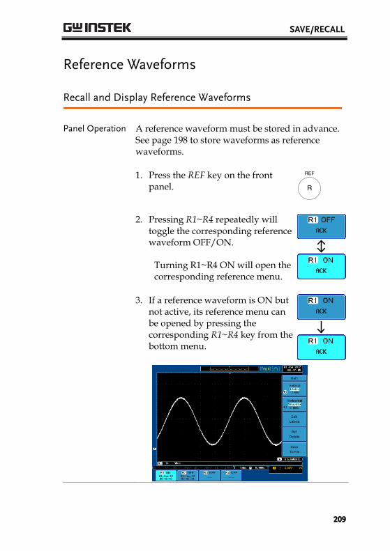
SAVE/RECALL
209
Reference Waveforms
Recall and Display Reference Waveforms
Panel Operation A reference waveform must be stored in advance. See page 198 to store waveforms as reference waveforms.
1. Press the REF key on the front panel. R
REF
2. Pressing R1~R4 repeatedly will toggle the corresponding reference waveform OFF/ON.
Turning R1~R4 ON will open the corresponding reference menu.
3. If a reference waveform is ON but not active, its reference menu can be opened by pressing the corresponding R1~R4 key from the bottom menu.
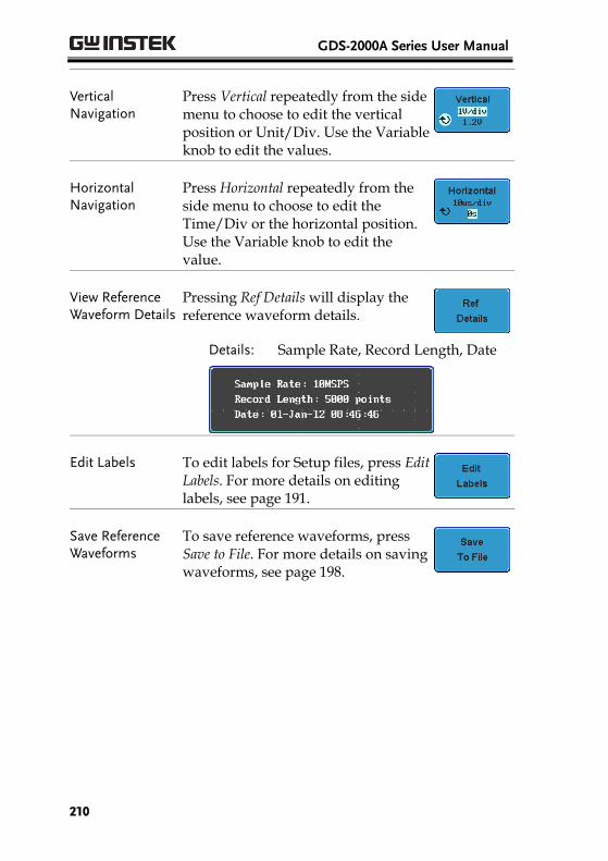
GDS-2000A Series User Manual
210
Vertical Navigation
Press Vertical repeatedly from the side menu to choose to edit the vertical position or Unit/Div. Use the Variable knob to edit the values.
Horizontal Navigation
Press Horizontal repeatedly from the side menu to choose to edit the Time/Div or the horizontal position. Use the Variable knob to edit the value.
View Reference Waveform Details
Pressing Ref Details will display the reference waveform details.
Details: Sample Rate, Record Length, Date
Edit Labels To edit labels for Setup files, press Edit Labels. For more details on editing labels, see page 191.
Save Reference Waveforms
To save reference waveforms, press Save to File. For more details on saving waveforms, see page 198.
FILE UTILITIES
211
FILE UTILITIES The file utilities are used each time files need to be saved to internal or external memory. The file utilities can create directories, delete directories, rename files as well as copy files from internal memory to USB. The File Utilities menu also sets the file path for saving and recalling files from the Save/Recall menu.
File Navigation ................................................................... 212 Create Folder ...................................................................... 214 Rename File ........................................................................ 215 Delete File ........................................................................... 216 Copy File to USB ............................................................... 217
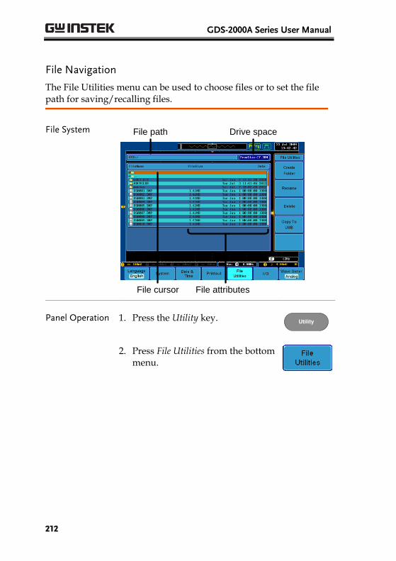
GDS-2000A Series User Manual
212
File Navigation
The File Utilities menu can be used to choose files or to set the file path for saving/recalling files.
File System File path Drive space
File cursor File attributes
Panel Operation 1. Press the Utility key. Utility
2. Press File Utilities from the bottom menu.
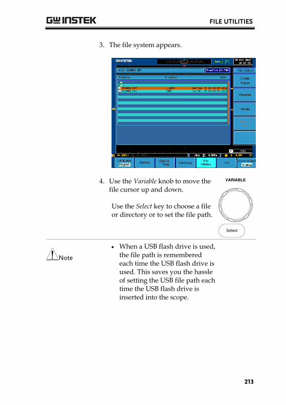
FILE UTILITIES
213
3. The file system appears.
4. Use the Variable knob to move the file cursor up and down.
Use the Select key to choose a file or directory or to set the file path.
VARIABLE
Select
Note
When a USB flash drive is used, the file path is remembered each time the USB flash drive is used. This saves you the hassle of setting the USB file path each time the USB flash drive is inserted into the scope.
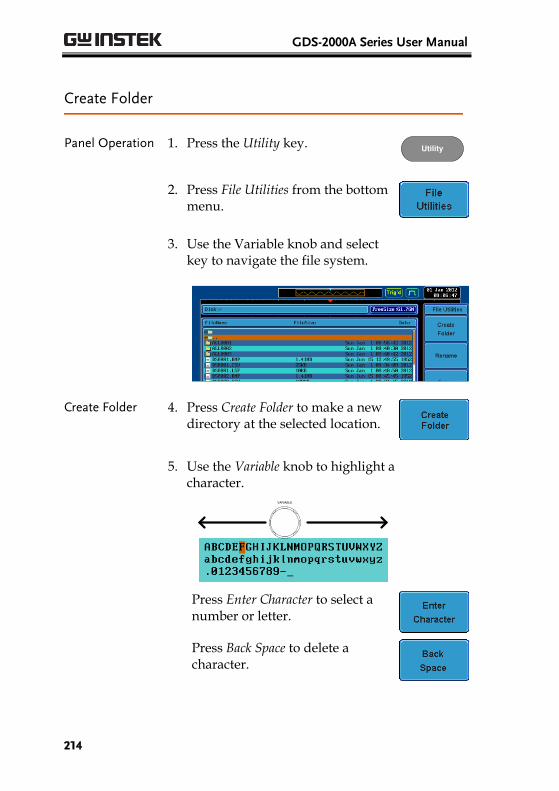
GDS-2000A Series User Manual
214
Create Folder
Panel Operation 1. Press the Utility key. Utility
2. Press File Utilities from the bottom menu.
3. Use the Variable knob and select key to navigate the file system.
Create Folder 4. Press Create Folder to make a new directory at the selected location.
5. Use the Variable knob to highlight a character.
VARIABLE
Press Enter Character to select a number or letter.
Press Back Space to delete a character.
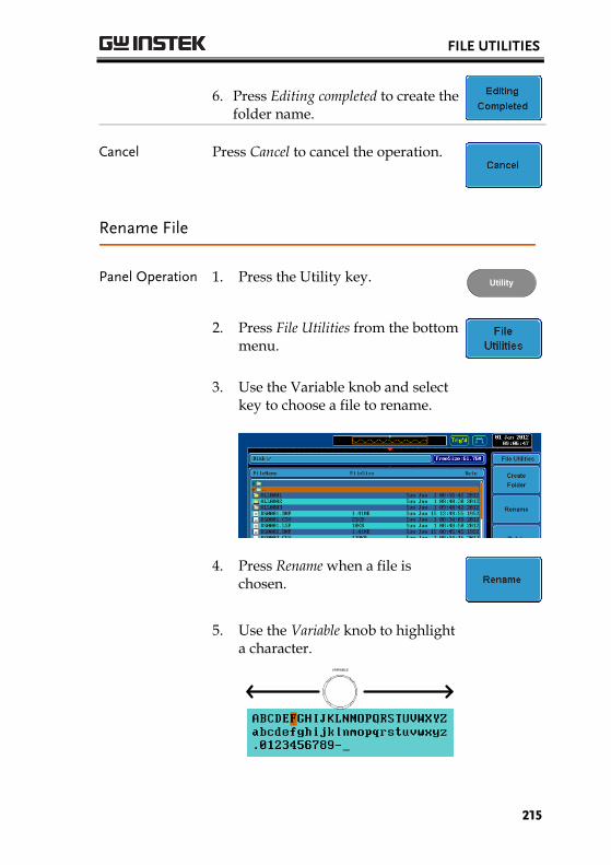
FILE UTILITIES
215
6. Press Editing completed to create the folder name.
Cancel Press Cancel to cancel the operation.
Rename File
Panel Operation 1. Press the Utility key. Utility
2. Press File Utilities from the bottom menu.
3. Use the Variable knob and select key to choose a file to rename.
4. Press Rename when a file is chosen.
5. Use the Variable knob to highlight a character.
VARIABLE
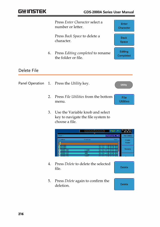
GDS-2000A Series User Manual
216
Press Enter Character select a number or letter.
Press Back Space to delete a character.
6. Press Editing completed to rename the folder or file.
Delete File
Panel Operation 1. Press the Utility key. Utility
2. Press File Utilities from the bottom menu.
3. Use the Variable knob and select key to navigate the file system to choose a file.
4. Press Delete to delete the selected file.
5. Press Delete again to confirm the deletion.
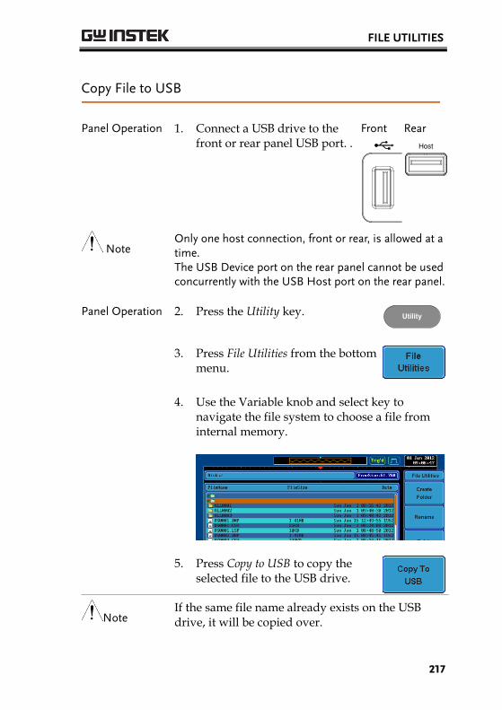
FILE UTILITIES
217
Copy File to USB
Panel Operation 1. Connect a USB drive to the front or rear panel USB port. .
Front
Rear
Host
Note Only one host connection, front or rear, is allowed at a time. The USB Device port on the rear panel cannot be used concurrently with the USB Host port on the rear panel.
Panel Operation 2. Press the Utility key. Utility
3. Press File Utilities from the bottom menu.
4. Use the Variable knob and select key to navigate the file system to choose a file from internal memory.
5. Press Copy to USB to copy the selected file to the USB drive.
Note If the same file name already exists on the USB drive, it will be copied over.
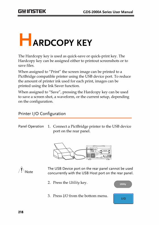
GDS-2000A Series User Manual
218
HARDCOPY KEY The Hardcopy key is used as quick-save or quick-print key. The Hardcopy key can be assigned either to printout screenshots or to save files.
When assigned to “Print” the screen image can be printed to a PictBridge compatible printer using the USB device port. To reduce the amount of printer ink used for each print, images can be printed using the Ink Saver function.
When assigned to “Save”, pressing the Hardcopy key can be used to save a screen shot, a waveform, or the current setup, depending on the configuration.
Printer I/O Configuration
Panel Operation
1. Connect a PictBridge printer to the USB device port on the rear panel.
Note The USB Device port on the rear panel cannot be used concurrently with the USB Host port on the rear panel.
2. Press the Utility key. Utility
3. Press I/O from the bottom menu.
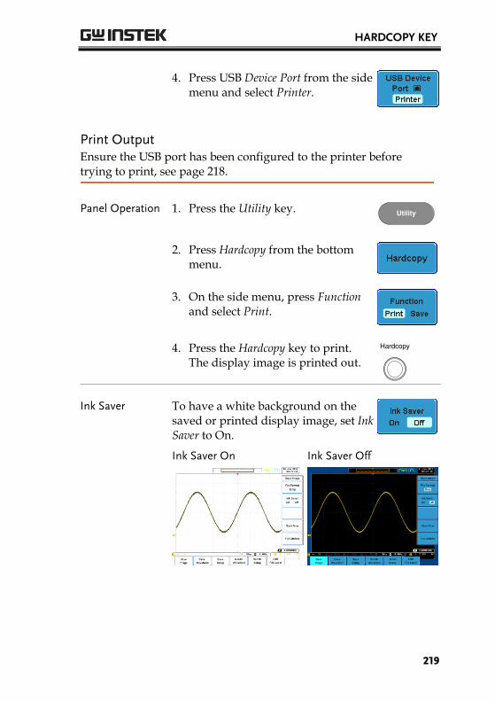
HARDCOPY KEY
219
4. Press USB Device Port from the side menu and select Printer.
Print Output Ensure the USB port has been configured to the printer before trying to print, see page 218.
Panel Operation 1. Press the Utility key. Utility
2. Press Hardcopy from the bottom menu.
3. On the side menu, press Function and select Print.
4. Press the Hardcopy key to print. The display image is printed out.
Hardcopy
Ink Saver To have a white background on the saved or printed display image, set Ink Saver to On.
Ink Saver On
Ink Saver Off
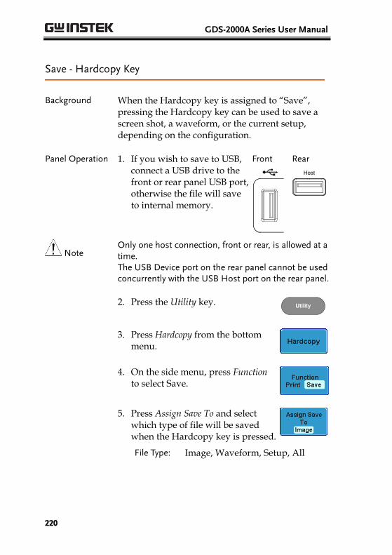
GDS-2000A Series User Manual
220
Save - Hardcopy Key
Background When the Hardcopy key is assigned to “Save”, pressing the Hardcopy key can be used to save a screen shot, a waveform, or the current setup, depending on the configuration.
Panel Operation 1. If you wish to save to USB, connect a USB drive to the front or rear panel USB port, otherwise the file will save to internal memory.
Front
Rear
Host
Note Only one host connection, front or rear, is allowed at a time. The USB Device port on the rear panel cannot be used concurrently with the USB Host port on the rear panel.
2. Press the Utility key. Utility
3. Press Hardcopy from the bottom menu.
4. On the side menu, press Function to select Save.
5. Press Assign Save To and select which type of file will be saved when the Hardcopy key is pressed.
File Type: Image, Waveform, Setup, All
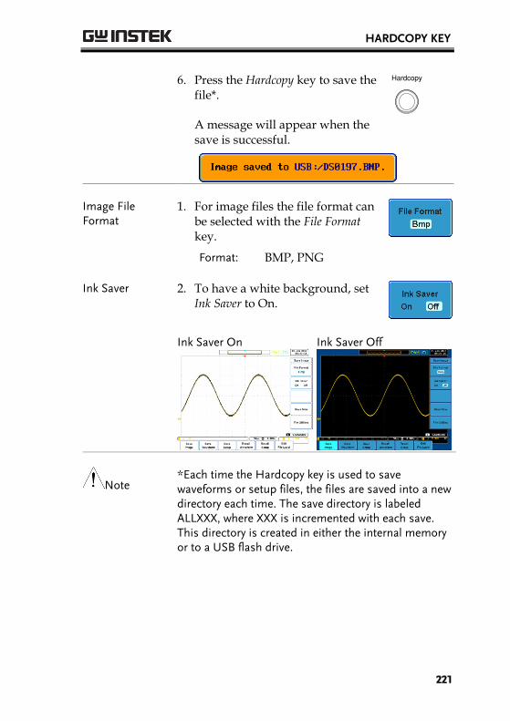
HARDCOPY KEY
221
6. Press the Hardcopy key to save the file*.
A message will appear when the save is successful.
Hardcopy
Image File Format
1. For image files the file format can be selected with the File Format key.
Format: BMP, PNG
Ink Saver 2. To have a white background, set Ink Saver to On.
Ink Saver On
Ink Saver Off
Note *Each time the Hardcopy key is used to save waveforms or setup files, the files are saved into a new directory each time. The save directory is labeled ALLXXX, where XXX is incremented with each save. This directory is created in either the internal memory or to a USB flash drive.
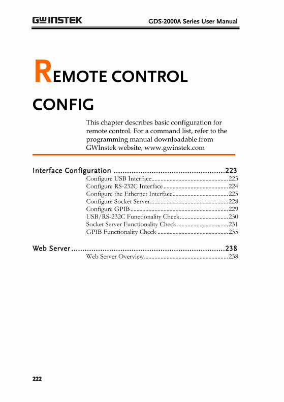
GDS-2000A Series User Manual
222
REMOTE CONTROL
CONFIG This chapter describes basic configuration for remote control. For a command list, refer to the programming manual downloadable from GWInstek website, www.gwinstek.com
Interface Configuration .................................................. 223 Configure USB Interface................................................... 223 Configure RS-232C Interface ........................................... 224 Configure the Ethernet Interface ..................................... 225 Configure Socket Server .................................................... 228 Configure GPIB ................................................................. 229 USB/RS-232C Functionality Check ................................ 230 Socket Server Functionality Check .................................. 231 GPIB Functionality Check ............................................... 235
Web Server ..................................................................... 238 Web Server Overview ........................................................ 238
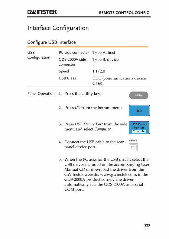
REMOTE CONTROL CONFIG
223
Interface Configuration
Configure USB Interface
USB Configuration
PC side connector Type A, host
GDS-2000A side connector
Type B, device
Speed 1.1/2.0
USB Class CDC (communications device class)
Panel Operation 1. Press the Utility key. Utility
2. Press I/O from the bottom menu.
3. Press USB Device Port from the side menu and select Computer.
4. Connect the USB cable to the rear panel device port.
5. When the PC asks for the USB driver, select the USB driver included on the accompanying User Manual CD or download the driver from the GW Instek website, www.gwinstek.com, in the GDS-2000A product corner. The driver automatically sets the GDS-2000A as a serial COM port.
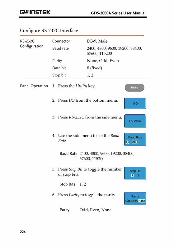
GDS-2000A Series User Manual
224
Configure RS-232C Interface
RS-232C Configuration
Connector DB-9, Male
Baud rate 2400, 4800, 9600, 19200, 38400, 57600, 115200
Parity None, Odd, Even
Data bit 8 (fixed)
Stop bit 1, 2
Panel Operation 1. Press the Utility key. Utility
2. Press I/O from the bottom menu.
3. Press RS-232C from the side menu.
4. Use the side menu to set the Baud Rate.
Baud Rate 2400, 4800, 9600, 19200, 38400, 57600, 115200
5. Press Stop Bit to toggle the number of stop bits.
Stop Bits 1, 2
6. Press Parity to toggle the parity.
Parity Odd, Even, None
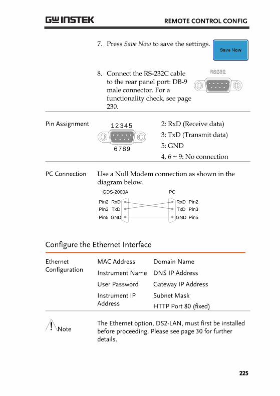
REMOTE CONTROL CONFIG
225
7. Press Save Now to save the settings.
8. Connect the RS-232C cable to the rear panel port: DB-9 male connector. For a functionality check, see page 230.
Pin Assignment 12 34 5
6789
2: RxD (Receive data)
3: TxD (Transmit data)
5: GND
4, 6 ~ 9: No connection
PC Connection Use a Null Modem connection as shown in the diagram below.
GDS-2000A PC
RxDPin2 RxD Pin2
GNDPin5 GND Pin5
TxD Pin3TxDPin3
Configure the Ethernet Interface
Ethernet Configuration
MAC Address Domain Name
Instrument Name DNS IP Address
User Password Gateway IP Address
Instrument IP Address
Subnet Mask
HTTP Port 80 (fixed)
Note The Ethernet option, DS2-LAN, must first be installed before proceeding. Please see page 30 for further details.
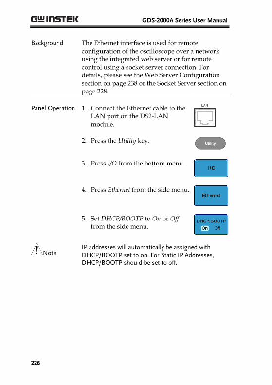
GDS-2000A Series User Manual
226
Background The Ethernet interface is used for remote configuration of the oscilloscope over a network using the integrated web server or for remote control using a socket server connection. For details, please see the Web Server Configuration section on page 238 or the Socket Server section on page 228.
Panel Operation 1. Connect the Ethernet cable to the LAN port on the DS2-LAN module.
2. Press the Utility key. Utility
3. Press I/O from the bottom menu.
4. Press Ethernet from the side menu.
5. Set DHCP/BOOTP to On or Off from the side menu.
Note IP addresses will automatically be assigned with DHCP/BOOTP set to on. For Static IP Addresses, DHCP/BOOTP should be set to off.
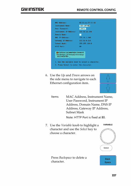
REMOTE CONTROL CONFIG
227
6. Use the Up and Down arrows on the side menu to navigate to each Ethernet configuration item.
Items MAC Address, Instrument Name, User Password, Instrument IP Address, Domain Name, DNS IP Address, Gateway IP Address, Subnet Mask
Note: HTTP Port is fixed at 80.
7. Use the Variable knob to highlight a character and use the Select key to choose a character.
VARIABLE
Select
Press Backspace to delete a character.
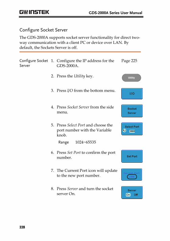
GDS-2000A Series User Manual
228
Configure Socket Server
The GDS-2000A supports socket server functionality for direct two-way communication with a client PC or device over LAN. By default, the Sockets Server is off.
Configure Socket Server
1. Configure the IP address for the GDS-2000A.
Page 225
2. Press the Utility key. Utility
3. Press I/O from the bottom menu.
4. Press Socket Server from the side menu.
5. Press Select Port and choose the port number with the Variable knob.
Range 1024~65535
6. Press Set Port to confirm the port number.
7. The Current Port icon will update to the new port number.
8. Press Server and turn the socket server On.
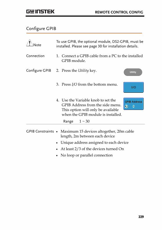
REMOTE CONTROL CONFIG
229
Configure GPIB
Note To use GPIB, the optional module, DS2-GPIB, must be installed. Please see page 30 for installation details.
Connection 1. Connect a GPIB cable from a PC to the installed GPIB module.
Configure GPIB 2. Press the Utility key. Utility
3. Press I/O from the bottom menu.
4. Use the Variable knob to set the GPIB Address from the side menu. This option will only be available when the GPIB module is installed.
Range 1 ~ 30
GPIB Constraints Maximum 15 devices altogether, 20m cable length, 2m between each device
Unique address assigned to each device
At least 2/3 of the devices turned On
No loop or parallel connection
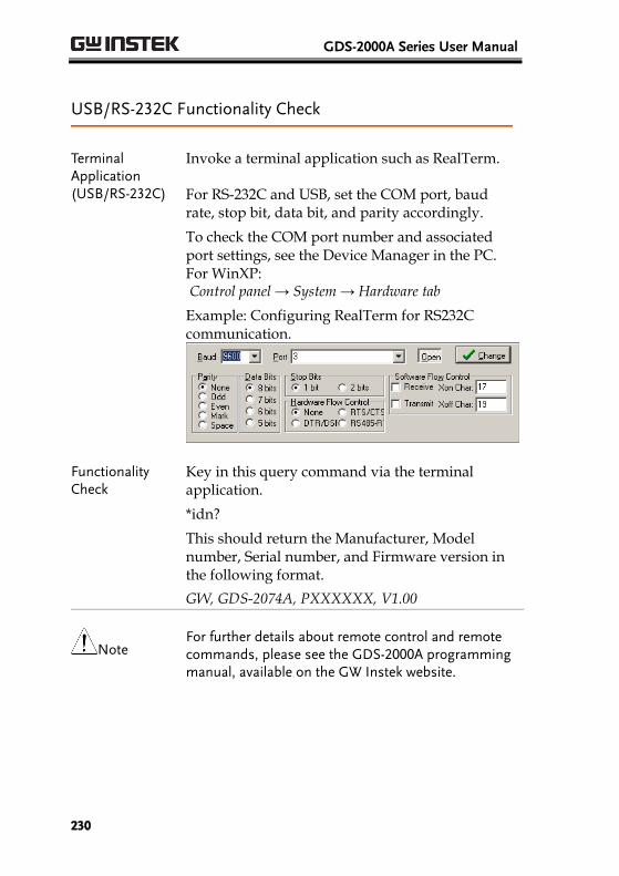
GDS-2000A Series User Manual
230
USB/RS-232C Functionality Check
Terminal Application (USB/RS-232C)
Invoke a terminal application such as RealTerm.
For RS-232C and USB, set the COM port, baud rate, stop bit, data bit, and parity accordingly.
To check the COM port number and associated port settings, see the Device Manager in the PC. For WinXP: Control panel → System → Hardware tab
Example: Configuring RealTerm for RS232C communication.
Functionality Check
Key in this query command via the terminal application.
*idn?
This should return the Manufacturer, Model number, Serial number, and Firmware version in the following format.
GW, GDS-2074A, PXXXXXX, V1.00
Note For further details about remote control and remote commands, please see the GDS-2000A programming manual, available on the GW Instek website.
REMOTE CONTROL CONFIG
231
Socket Server Functionality Check
NI Measurement and Automation Explorer
To test the socket server functionality, National Instruments Measurement and Automation Explorer can be used. This program is available on the NI website, www.ni.com.
Operation 1. Start the NI Measurement and Automation Explorer (MAX) program. Using Windows, press:
Start>All Programs>National Instruments>Measurement & Automation
2. From the Configuration panel access;
My System>Devices and Interfaces>Network Devices
3. Press Add New Network Device>Visa TCP/IP Resource…
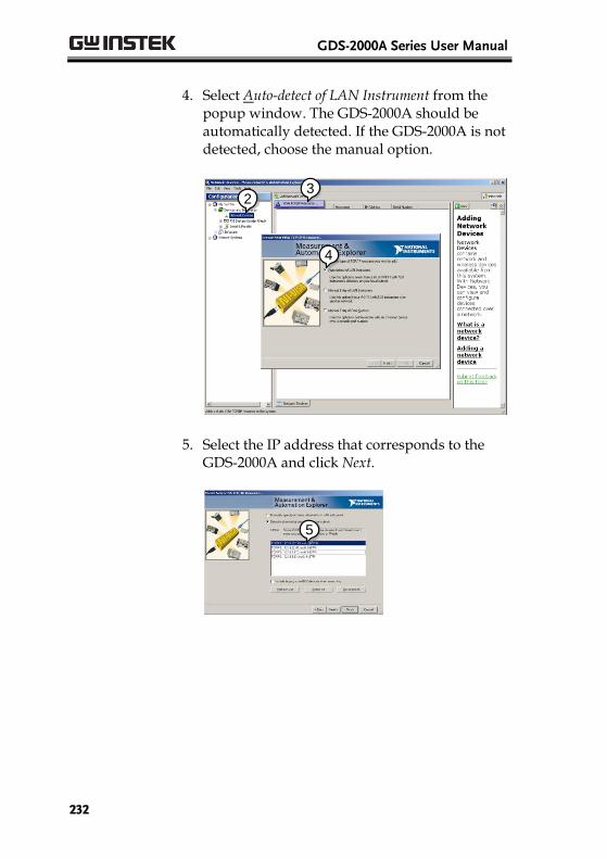
GDS-2000A Series User Manual
232
4. Select Auto-detect of LAN Instrument from the popup window. The GDS-2000A should be automatically detected. If the GDS-2000A is not detected, choose the manual option.
2
3
4
5. Select the IP address that corresponds to the GDS-2000A and click Next.
5

REMOTE CONTROL CONFIG
233
6. The GDS-2000A will now appear under Network Devices in the Configuration Panel.
Functionality Check
7. Click the Open Visa Test Panel to send a remote command to the GDS-2000A.
6
7
8. Click on the viWrite tab. The *IDN? query should already be in the buffer area.
9. Click Execute to execute the query.
8
9
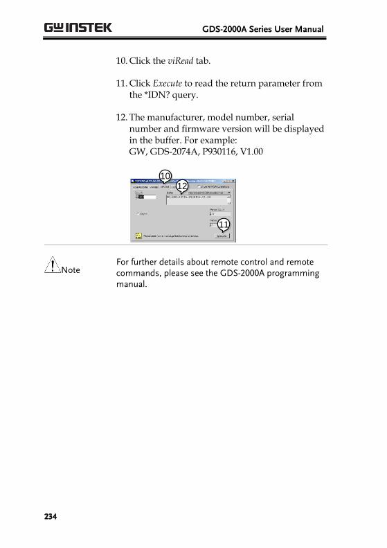
GDS-2000A Series User Manual
234
10. Click the viRead tab.
11. Click Execute to read the return parameter from the *IDN? query.
12. The manufacturer, model number, serial number and firmware version will be displayed in the buffer. For example: GW, GDS-2074A, P930116, V1.00
10
11
12
Note For further details about remote control and remote commands, please see the GDS-2000A programming manual.
REMOTE CONTROL CONFIG
235
GPIB Functionality Check
To check that the GPIB connection is working, National Instruments Measurement & Automation Explorer (MAX) can be used. The following function check is based on version 4.6.2.
For further information about National Instruments, please see the NI website at www.ni.com.
Operation 1. Start the NI Measurement and Automation Explorer (MAX) program. Using Windows, press:
Start>All Programs>National Instruments>Measurement & Automation
2. From the Configuration panel access;
My System>Devices and Interfaces>GPIB0
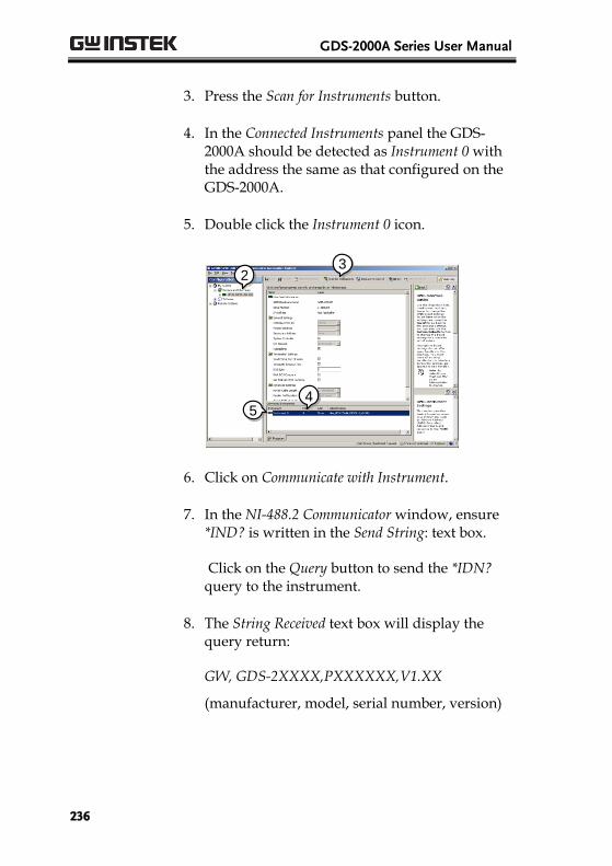
GDS-2000A Series User Manual
236
3. Press the Scan for Instruments button.
4. In the Connected Instruments panel the GDS-2000A should be detected as Instrument 0 with the address the same as that configured on the GDS-2000A.
5. Double click the Instrument 0 icon.
2
3
45
6. Click on Communicate with Instrument.
7. In the NI-488.2 Communicator window, ensure *IND? is written in the Send String: text box.
Click on the Query button to send the *IDN? query to the instrument.
8. The String Received text box will display the query return:
GW, GDS-2XXXX,PXXXXXX,V1.XX
(manufacturer, model, serial number, version)
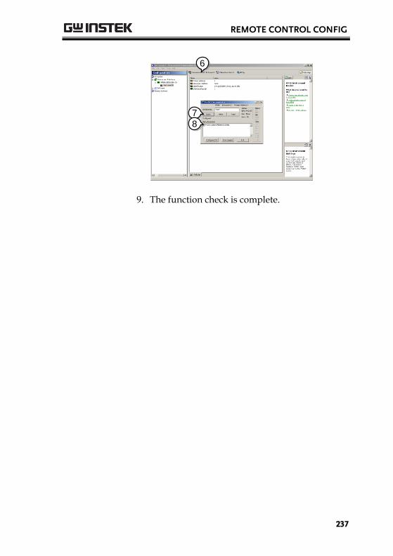
REMOTE CONTROL CONFIG
237
6
7
8
9. The function check is complete.
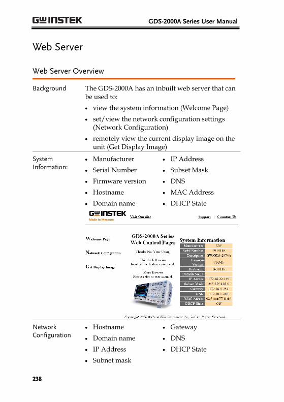
GDS-2000A Series User Manual
238
Web Server
Web Server Overview
Background The GDS-2000A has an inbuilt web server that can be used to:
view the system information (Welcome Page)
set/view the network configuration settings (Network Configuration)
remotely view the current display image on the unit (Get Display Image)
System Information:
Manufacturer
Serial Number
Firmware version
Hostname
Domain name
IP Address
Subset Mask
DNS
MAC Address
DHCP State
Network Configuration
Hostname
Domain name
IP Address
Subnet mask
Gateway
DNS
DHCP State
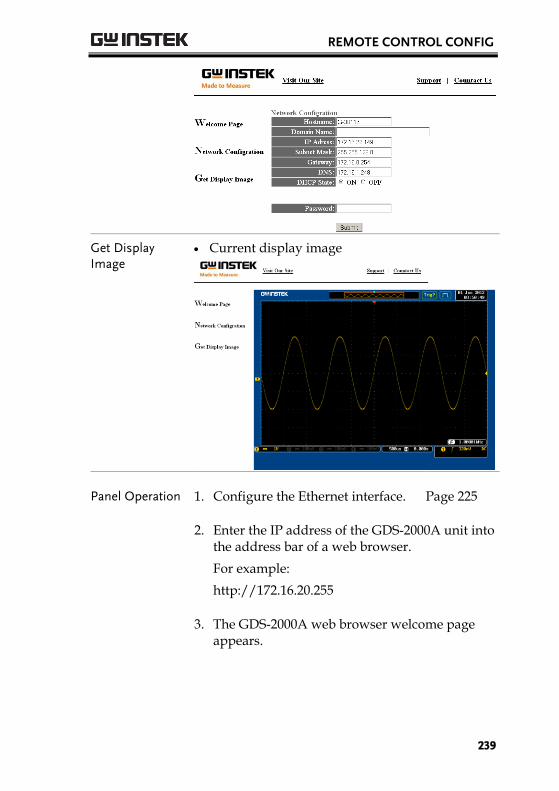
REMOTE CONTROL CONFIG
239
Get Display Image
Current display image
Panel Operation 1. Configure the Ethernet interface. Page 225
2. Enter the IP address of the GDS-2000A unit into the address bar of a web browser.
For example:
http://172.16.20.255
3. The GDS-2000A web browser welcome page appears.
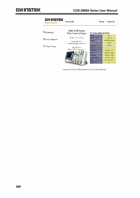
GDS-2000A Series User Manual
240
MAINTENANCE
241
MAINTENANCE Two types of maintenance operations are available: calibrate vertical accuracy, and compensate the probe. Run these operations when using the GDS-2000A in a new environment.
How to use SPC function ................................................. 242 Vertical Accuracy Calibration ........................................... 243 Probe Compensation ......................................................... 244
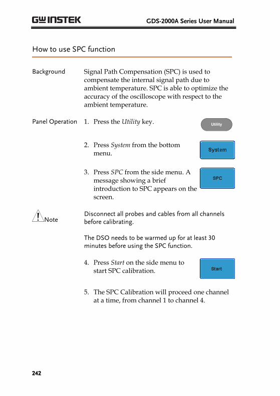
GDS-2000A Series User Manual
242
How to use SPC function
Background Signal Path Compensation (SPC) is used to compensate the internal signal path due to ambient temperature. SPC is able to optimize the accuracy of the oscilloscope with respect to the ambient temperature.
Panel Operation 1. Press the Utility key. Utility
2. Press System from the bottom menu.
3. Press SPC from the side menu. A message showing a brief introduction to SPC appears on the screen.
Note Disconnect all probes and cables from all channels before calibrating.
The DSO needs to be warmed up for at least 30 minutes before using the SPC function.
4. Press Start on the side menu to start SPC calibration.
5. The SPC Calibration will proceed one channel at a time, from channel 1 to channel 4.
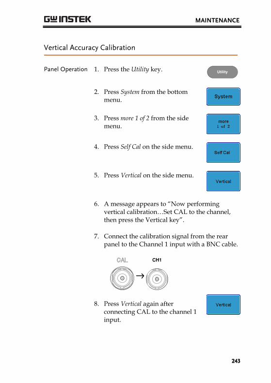
MAINTENANCE
243
Vertical Accuracy Calibration
Panel Operation 1. Press the Utility key. Utility
2. Press System from the bottom menu.
3. Press more 1 of 2 from the side menu.
4. Press Self Cal on the side menu.
5. Press Vertical on the side menu.
6. A message appears to “Now performing vertical calibration…Set CAL to the channel, then press the Vertical key”.
7. Connect the calibration signal from the rear panel to the Channel 1 input with a BNC cable.
CH1
8. Press Vertical again after connecting CAL to the channel 1 input.
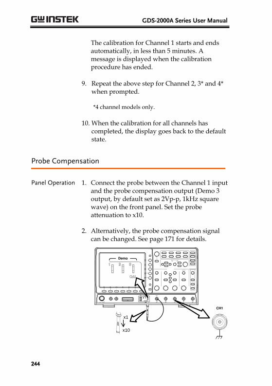
GDS-2000A Series User Manual
244
The calibration for Channel 1 starts and ends automatically, in less than 5 minutes. A message is displayed when the calibration procedure has ended.
9. Repeat the above step for Channel 2, 3* and 4* when prompted.
*4 channel models only.
10. When the calibration for all channels has completed, the display goes back to the default state.
Probe Compensation
Panel Operation 1. Connect the probe between the Channel 1 input and the probe compensation output (Demo 3 output, by default set as 2Vp-p, 1kHz square wave) on the front panel. Set the probe attenuation to x10.
2. Alternatively, the probe compensation signal can be changed. See page 171 for details.
POSITION
CH1Demo
x1
x10
X10
X1 CH1
Demo
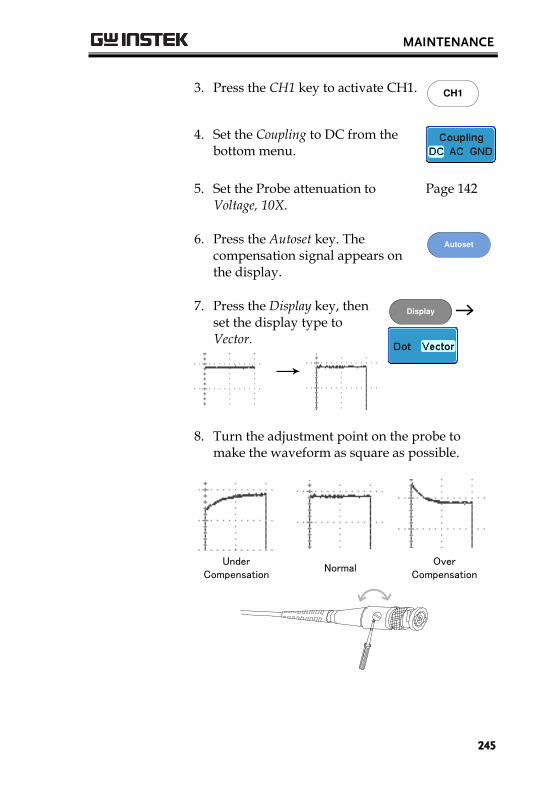
MAINTENANCE
245
3. Press the CH1 key to activate CH1. CH1
4. Set the Coupling to DC from the bottom menu.
5. Set the Probe attenuation to Voltage, 10X.
Page 142
6. Press the Autoset key. The compensation signal appears on the display.
Autoset
7. Press the Display key, then set the display type to Vector.
Display
8. Turn the adjustment point on the probe to make the waveform as square as possible.
Under Compensation
NormalOver
Compensation
GDS-2000A Series User Manual
246
FAQ
• I connected the signal but it does not appear on the display.
• I want to remove the (Measurement result / FFT result / Help contents) from the display.
• The waveform does not update (frozen).
• The probe waveform is distorted.
• Autoset does not catch the signal well.
• I can’t save files to the internal memory.
• The display image printout is too dark on the background.
• The date and time settings are not correct.
• The accuracy does not match the specification.
I connected the signal but it does not appear on the display.
Make sure you have activated the channel by pressing the Channel key (the channel key lights up).
I want to remove the (Measurement result / FFT result /
Help contents) from the display.
To clear automatic measurement results, press the Measure key, select Remove Measurement and choose Remove All. See page 78.
To clear individual measurements from the screen, press the Measure key, select Display All and choose Off. See page 80.
To clear the FFT result, press the Math key twice. See page 93 for details.
To clear Help result, press the Help key again. See page 63 for
FAQ
247
details.
The waveform does not update (frozen).
Press the Run/Stop key to unfreeze the waveform. See page 68 for details.
If this does not help, the trigger mode might be set to Single. Press the Single key to exit Single mode. See page 68 for Single trigger details.
The probe waveform is distorted.
You might need to compensate the probe. For details, see page 244.
Autoset does not catch the signal well.
The Autoset function cannot catch signals under 30mV or 20Hz. Please use the manual operation. See page 66 for Autoset details.
I can’t save files to the internal memory.
If a USB stick is inserted into one of the USB slots and you wish to save to the scope internal memory, press the Utilities key and set the file path to internal memory.
The display image printout is too dark on the background.
Use the Ink Saver function which reverses the background color. For details, see page 219.
The date and time settings are not correct.
For date and time setting details, please see page 170. If it does not help, the internal battery controlling the clock might be worn out. Contact your dealer or GWInstek.

GDS-2000A Series User Manual
248
The accuracy does not match the specification.
Make sure the device is powered On for at least 30 minutes, within +20°C~+30°C. This is necessary to stabilize the unit to match the specification.
For more information, contact your local dealer or GWInstek at www.gwinstek.com / [email protected].
APPENDIX
249
APPENDIX
GDS-2000A Specifications The specifications apply when the GDS-2000A is powered on for at least 30 minutes under +20°C~+30°C.
Model-specific
GDS-2072A Channels 2 + Ext Bandwidth DC ~ 70MHz (–3dB) GDS-2074A Channels 4 + Ext Bandwidth DC ~ 70MHz (–3dB) GDS-2102A Channels 2 + Ext Bandwidth DC ~ 100MHz (–3dB) GDS-2104A Channels 4 + Ext Bandwidth DC ~ 100MHz (–3dB) GDS-2202A Channels 2 + Ext Bandwidth DC ~ 200MHz (–3dB) GDS-2204A Channels 4 + Ext Bandwidth DC ~ 200MHz (–3dB) GDS-2302A Channels 2 + Ext Bandwidth DC ~ 300MHz (–3dB) GDS-2304A Channels 4 + Ext Bandwidth DC ~ 300MHz (–3dB)
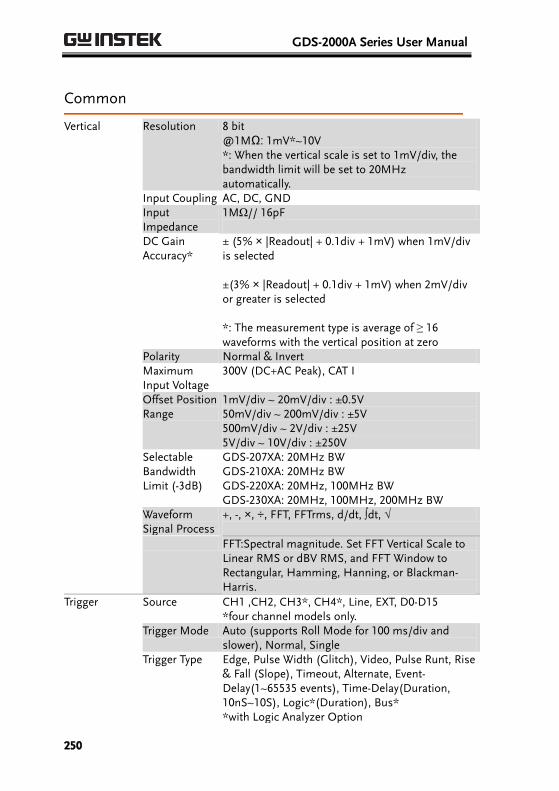
GDS-2000A Series User Manual
250
Common
Vertical Resolution 8 bit @1MΩ: 1mV*~10V *: When the vertical scale is set to 1mV/div, the bandwidth limit will be set to 20MHz automatically.
Input Coupling AC, DC, GND Input
Impedance 1MΩ// 16pF
DC Gain Accuracy*
± (5% × |Readout| + 0.1div + 1mV) when 1mV/div is selected ±(3% × |Readout| + 0.1div + 1mV) when 2mV/div or greater is selected *: The measurement type is average of ≥ 16 waveforms with the vertical position at zero
Polarity Normal & Invert Maximum
Input Voltage 300V (DC+AC Peak), CAT I
Offset Position Range
1mV/div ~ 20mV/div : ±0.5V 50mV/div ~ 200mV/div : ±5V 500mV/div ~ 2V/div : ±25V 5V/div ~ 10V/div : ±250V
Selectable Bandwidth Limit (-3dB)
GDS-207XA: 20MHz BW GDS-210XA: 20MHz BW GDS-220XA: 20MHz, 100MHz BW GDS-230XA: 20MHz, 100MHz, 200MHz BW
Waveform Signal Process
+, -, ×, ÷, FFT, FFTrms, d/dt, ∫dt, √
FFT:Spectral magnitude. Set FFT Vertical Scale to Linear RMS or dBV RMS, and FFT Window to Rectangular, Hamming, Hanning, or Blackman-Harris.
Trigger Source CH1 ,CH2, CH3*, CH4*, Line, EXT, D0-D15 *four channel models only.
Trigger Mode Auto (supports Roll Mode for 100 ms/div and slower), Normal, Single
Trigger Type Edge, Pulse Width (Glitch), Video, Pulse Runt, Rise & Fall (Slope), Timeout, Alternate, Event-Delay(1~65535 events), Time-Delay(Duration, 10nS~10S), Logic*(Duration), Bus* *with Logic Analyzer Option
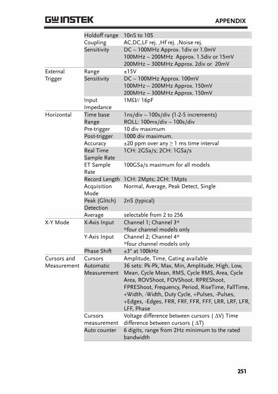
APPENDIX
251
Holdoff range 10nS to 10S Coupling AC,DC,LF rej. ,Hf rej. ,Noise rej. Sensitivity DC ~ 100MHz Approx. 1div or 1.0mV
100MHz ~ 200MHz Approx. 1.5div or 15mV 200MHz ~ 300MHz Approx. 2div or 20mV
External Trigger
Range ±15V Sensitivity DC ~ 100MHz Approx. 100mV
100MHz ~ 200MHz Approx. 150mV 200MHz ~ 300MHz Approx. 150mV
Input Impedance
1MΩ// 16pF
Horizontal Time base Range
1ns/div ~ 100s/div (1-2-5 increments) ROLL: 100ms/div ~ 100s/div
Pre-trigger 10 div maximum Post-trigger 1000 div maximum. Accuracy ±20 ppm over any ≥ 1 ms time interval Real Time
Sample Rate 1CH: 2GSa/s; 2CH: 1GSa/s
ET Sample Rate
100GSa/s maximum for all models
Record Length 1CH: 2Mpts; 2CH: 1Mpts Acquisition
Mode Normal, Average, Peak Detect, Single
Peak (Glitch) Detection
2nS (typical)
Average selectable from 2 to 256
X-Y Mode X-Axis Input Channel 1; Channel 3* *four channel models only
Y-Axis Input Channel 2; Channel 4* *four channel models only
Phase Shift ±3° at 100kHz
Cursors and Measurement
Cursors Amplitude, Time, Gating available Automatic Measurement
36 sets: Pk-Pk, Max, Min, Amplitude, High, Low, Mean, Cycle Mean, RMS, Cycle RMS, Area, Cycle Area, ROVShoot, FOVShoot, RPREShoot, FPREShoot, Frequency, Period, RiseTime, FallTime, +Width, -Width, Duty Cycle, +Pulses, -Pulses, +Edges, -Edges, FRR, FRF, FFR, FFF, LRR, LRF, LFR, LFF, Phase
Cursors measurement
Voltage difference between cursors ( ∆V) Time difference between cursors ( ∆T)
Auto counter 6 digits, range from 2Hz minimum to the rated bandwidth
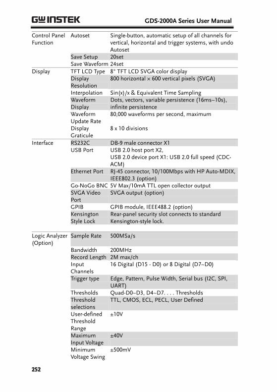
GDS-2000A Series User Manual
252
Control Panel Function
Autoset Single-button, automatic setup of all channels for vertical, horizontal and trigger systems, with undo Autoset
Save Setup 20set Save Waveform 24set
Display TFT LCD Type 8" TFT LCD SVGA color display Display
Resolution 800 horizontal × 600 vertical pixels (SVGA)
Interpolation Sin(x)/x & Equivalent Time Sampling Waveform
Display Dots, vectors, variable persistence (16ms~10s), infinite persistence
Waveform Update Rate
80,000 waveforms per second, maximum
Display Graticule
8 x 10 divisions
Interface RS232C DB-9 male connector X1 USB Port USB 2.0 host port X2,
USB 2.0 device port X1: USB 2.0 full speed (CDC-ACM)
Ethernet Port RJ-45 connector, 10/100Mbps with HP Auto-MDIX, IEEE802.3 (option)
Go-NoGo BNC 5V Max/10mA TTL open collector output SVGA Video
Port SVGA output (option)
GPIB GPIB module, IEEE488.2 (option) Kensington
Style Lock Rear-panel security slot connects to standard Kensington-style lock.
Logic Analyzer (Option)
Sample Rate 500MSa/s
Bandwidth 200MHz Record Length 2M max/ch Input
Channels 16 Digital (D15 - D0) or 8 Digital (D7~D0)
Trigger type Edge, Pattern, Pulse Width, Serial bus (I2C, SPI, UART)
Thresholds Quad-D0~D3, D4~D7. . . . Thresholds Threshold
selections TTL, CMOS, ECL, PECL, User Defined
User-defined Threshold Range
±10V
Maximum Input Voltage
±40V
Minimum Voltage Swing
±500mV
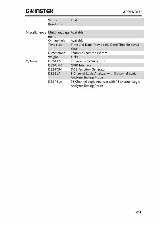
APPENDIX
253
Vertical Resolution
1 bit
Miscellaneous Multi-language
menu Available
On-line help Available Time clock Time and Date ,Provide the Date/Time for saved
data Dimensions 380mmX220mmX145mm Weight 4.2kg
Options DS2-LAN Ethernet & SVGA output DS2-GPIB GPIB Interface DS2-FGN DDS Function Generator DS2-8LA 8-Channel Logic Analyzer with 8-channel Logic
Analyzer Testing Probe DS2-16LA 16-Channel Logic Analyzer with 16-channel Logic
Analyzer Testing Probe
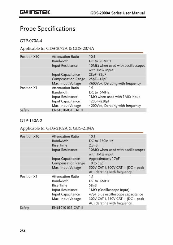
GDS-2000A Series User Manual
254
Probe Specifications
GTP-070A-4
Applicable to: GDS-2072A & GDS-2074A
Position X10 Attenuation Ratio 10:1 Bandwidth DC to 70MHz Input Resistance 10MΩ when used with oscilloscopes
with 1MΩ input. Input Capacitance 28pF~32pF Compensation Range 25pF~ 45pF Max. Input Voltage ≤600Vpk, Derating with frequency Position X1 Attenuation Ratio 1:1 Bandwidth DC to 6MHz Input Resistance 1MΩ when used with 1MΩ input Input Capacitance 120pF~220pF Max. Input Voltage ≤200Vpk, Derating with frequency Safety EN61010-031 CAT II
GTP-150A-2
Applicable to: GDS-2102A & GDS-2104A
Position X10 Attenuation Ratio 10:1 Bandwidth DC to 150MHz Rise Time 2.3nS Input Resistance 10MΩ when used with oscilloscopes
with 1MΩ input. Input Capacitance Approximately 17pF Compensation Range 10 to 35pF Max. Input Voltage 500V CAT I, 300V CAT II (DC + peak
AC) derating with frequency. Position X1 Attenuation Ratio 1:1 Bandwidth DC to 6MHz Rise Time 58nS Input Resistance 1MΩ (Oscilloscope Input) Input Capacitance 47pF plus oscilloscope capacitance Max. Input Voltage 300V CAT I, 150V CAT II (DC + peak
AC) derating with frequency. Safety EN61010-031 CAT II
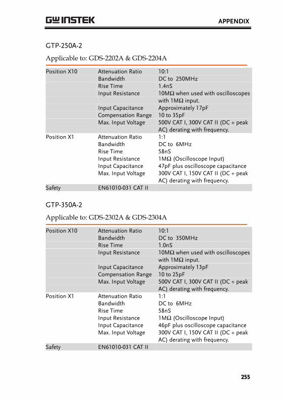
APPENDIX
255
GTP-250A-2
Applicable to: GDS-2202A & GDS-2204A
Position X10 Attenuation Ratio 10:1 Bandwidth DC to 250MHz Rise Time 1.4nS Input Resistance 10MΩ when used with oscilloscopes
with 1MΩ input. Input Capacitance Approximately 17pF Compensation Range 10 to 35pF Max. Input Voltage 500V CAT I, 300V CAT II (DC + peak
AC) derating with frequency. Position X1 Attenuation Ratio 1:1 Bandwidth DC to 6MHz Rise Time 58nS Input Resistance 1MΩ (Oscilloscope Input) Input Capacitance 47pF plus oscilloscope capacitance Max. Input Voltage 300V CAT I, 150V CAT II (DC + peak
AC) derating with frequency. Safety EN61010-031 CAT II
GTP-350A-2
Applicable to: GDS-2302A & GDS-2304A
Position X10 Attenuation Ratio 10:1 Bandwidth DC to 350MHz Rise Time 1.0nS Input Resistance 10MΩ when used with oscilloscopes
with 1MΩ input. Input Capacitance Approximately 13pF Compensation Range 10 to 25pF Max. Input Voltage 500V CAT I, 300V CAT II (DC + peak
AC) derating with frequency. Position X1 Attenuation Ratio 1:1 Bandwidth DC to 6MHz Rise Time 58nS Input Resistance 1MΩ (Oscilloscope Input) Input Capacitance 46pF plus oscilloscope capacitance Max. Input Voltage 300V CAT I, 150V CAT II (DC + peak
AC) derating with frequency. Safety EN61010-031 CAT II
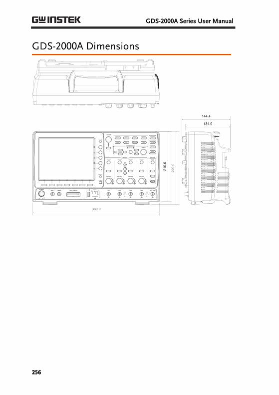
GDS-2000A Series User Manual
256
GDS-2000A Dimensions
POWER
CH1 CH2
POSITION TIME/DIV
POSITIONPOSITION
VOLTS/DIV VOLTS/DIV
Autoset
Menu
50 %
Force-Trig
Select
TRIGGER
HORIZONTAL
VARIABLE
Measure Cursor
Display Help Save/Recall Utility
Acquire
Single
Run/Stop
Search
Set/Clear
CH3 CH4
POSITION POSITION
VOLTS/DIV VOLTS/DIV
VERTICAL
M
R
B
Test
CH1 CH2 CH3 CH4 EXT TRIG
CAT
MW 16pF
300Vpk MAX.
1
CAT
MW 16pF
300Vpk MAX.
Hardcopy
Option
Menu Off
LEVEL
Zoom
MATH
REF
DemoLogic Analyzer
1
BUS
GEN 1 GEN 2
Default
380.0
210.
0
220.
0
134.0
144.4
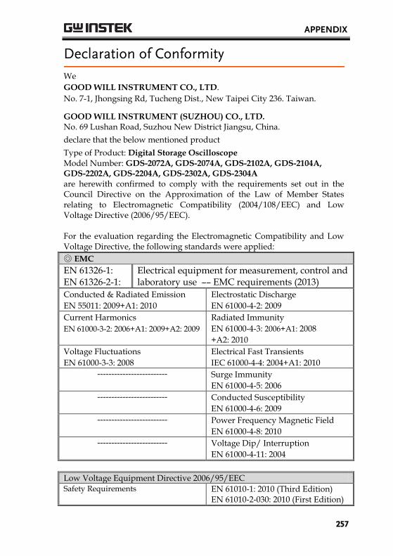
APPENDIX
257
Declaration of Conformity
We
GOOD WILL INSTRUMENT CO., LTD.
No. 7-1, Jhongsing Rd, Tucheng Dist., New Taipei City 236. Taiwan.
GOOD WILL INSTRUMENT (SUZHOU) CO., LTD. No. 69 Lushan Road, Suzhou New District Jiangsu, China.
declare that the below mentioned product
Type of Product: Digital Storage Oscilloscope
Model Number: GDS-2072A, GDS-2074A, GDS-2102A, GDS-2104A, GDS-2202A, GDS-2204A, GDS-2302A, GDS-2304A are herewith confirmed to comply with the requirements set out in the Council Directive on the Approximation of the Law of Member States relating to Electromagnetic Compatibility (2004/108/EEC) and Low Voltage Directive (2006/95/EEC). For the evaluation regarding the Electromagnetic Compatibility and Low Voltage Directive, the following standards were applied:
EMC
EN 61326-1: EN 61326-2-1:
Electrical equipment for measurement, control and laboratory use –– EMC requirements (20 13)
Conducted & Radiated Emission
EN 55011: 2009+A1: 2010
Electrostatic Discharge
EN 61000-4-2: 2009
Current Harmonics
EN 61000-3-2: 2006+A1: 2009+A2: 2009
Radiated Immunity
EN 61000-4-3: 2006+A1: 2008
+A2: 2010
Voltage Fluctuations
EN 61000-3-3: 2008
Electrical Fast Transients
IEC 61000-4-4: 2004+A1: 2010
------------------------- Surge Immunity
EN 61000-4-5: 2006
------------------------- Conducted Susceptibility
EN 61000-4-6: 2009
------------------------- Power Frequency Magnetic Field
EN 61000-4-8: 2010
------------------------- Voltage Dip/ Interruption
EN 61000-4-11: 2004
Low Voltage Equipment Directive 2006/95/EEC Safety Requirements EN 61010-1: 2010
EN 61010-2-030: 2010 (First Edition) (Third Edition)
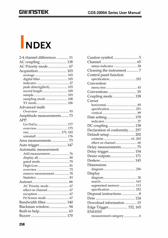
GDS-2000A Series User Manual
258
INDEX 2-4 channel differences ............. 11 AC coupling ............................. 138 AC Priority mode ...................... 67 Acquisition ............................... 103
average ......................................... 103 digital filter .................................. 105 indicator ......................................... 27 peak detect(glitch) ...................... 103 record length ............................... 109 sample .......................................... 103 sampling mode ........................... 108 XY mode ....................................... 106
Advanced math Overview ....................................... 93
Amplitude measurements ........ 73 APP.
Go-NoGo ...................................... 177 overview ...................................... 175 run ......................................... 175, 182 uninstall ....................................... 176
Area measurements .................. 73 Auto trigger .............................. 147 Automatic measurement
Add measurement ........................ 76 display all ....................................... 80 gated mode .................................... 79 High-Low ....................................... 81 overview ........................................ 72 remove measurement .................. 78 Statistics ......................................... 83
Autoset ........................................ 66 AC Priority mode ......................... 67 effect on channel ........................... 67 exception ........................................ 67 Fit Screen mode ............................ 67
Bandwidth filter....................... 140 Blackman window ..................... 94 Built-in help ................................ 63 Buzzer ....................................... 170
Caution symbol ............................ 5 Channel ....................................... 65
status indicator ............................. 28
Cleaning the instrument ............. 7 Control panel function
specification ................................. 252
Convention menu tree ....................................... 43
Conventions ............................... 35 Coupling mode ........................ 138 Cursor
horizontal ....................................... 85 specification ................................. 251 vertical ............................................ 89
Date setting ............................... 170 indicator ......................................... 27
DC coupling ............................. 138 Declaration of conformity ....... 257 Default setup ............................ 202
contents .................................. 61, 203 effect on channel ........................... 66
Delay measurements ................. 75 Delay trigger ............................. 154 Demo outputs ........................... 171 Deskew ...................................... 143 Dimensions
diagram ........................................ 256
Display diagram .......................................... 26 search ............................................ 163 segmented memory ................... 113 specification ................................. 252
Disposal instructions ................... 8 Dots ........................................... 124 Download information ............. 15 Edge Trigger ..................... 152, 165 EN61010
measurement category .................. 6
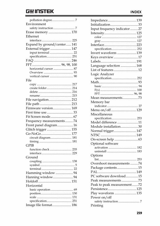
INDEX
259
pollution degree.............................. 7
Environment safety instruction ............................ 7
Erase memory .......................... 170 Ethernet
interface ........................................ 225
Expand by ground/center ...... 141 External trigger ........................ 147
input terminal ............................... 22 specification ................................. 251
FAQ ........................................... 246 FFT ................................. 96, 98, 100
horizontal cursor .......................... 87 Overview ....................................... 93 vertical cursor ............................... 90
File copy .............................................. 217 create folder ................................. 214 delete ............................................ 216 rename .......................................... 215
File navigation .......................... 212 File path .................................... 213 Firmware version ..................... 169 First time use .............................. 33 Fit Screen mode .......................... 67 Frequency measurements ......... 74 Front panel diagram .................. 16 Glitch trigger ............................ 155 Go-NoGo ................................... 177
circuit diagram ............................ 181 timing ........................................... 181
GPIB function check ............................. 235 interface ........................................ 229
Ground coupling ....................................... 138 symbol .............................................. 5 terminal .......................................... 22
Hamming window .................... 94 Hanning window ....................... 94 Holdoff ...................................... 151 Horizontal
basic operation .............................. 69 position ......................................... 130 scale .............................................. 131 specification ................................. 251
Image file format ...................... 186
Impedance ................................. 139 Initialization ................................ 33 Input frequency indicator ......... 27 Intensity ..................................... 125
color .............................................. 127 gray ............................................... 127
Interface ..................................... 223 specification ................................. 252
Invert waveform ...................... 139 Keys overview ............................ 17 Labels ......................................... 191 Language selection .................. 168 List of features ............................ 12 Logic Analyzer
specification ................................. 252
Math ............................................. 93 basic ................................................ 94 F(x) ................................................ 100 FFT ............................................ 96, 98
Mean measurements .................. 73 Memory bar
indicator ......................................... 27
Menu on/off ............................. 129 Miscellaneous
specification ................................. 253
Model difference ........................ 11 Module installation .................... 30 Normal trigger .......................... 147 NTSC ......................................... 149 On-screen help ........................... 63 Optional software
activation ..................................... 182 uninstall ....................................... 183
Options list .................................................. 253
Overshoot measurements ......... 74 Package contents ........................ 15 PAL ............................................ 149 PC software download .............. 15 Peak measurements ................... 73 Peak to peak measurement ....... 72 Persistence................................. 125 Play waveform ......................... 135 Power on/off
safety instruction ............................ 7
Printing
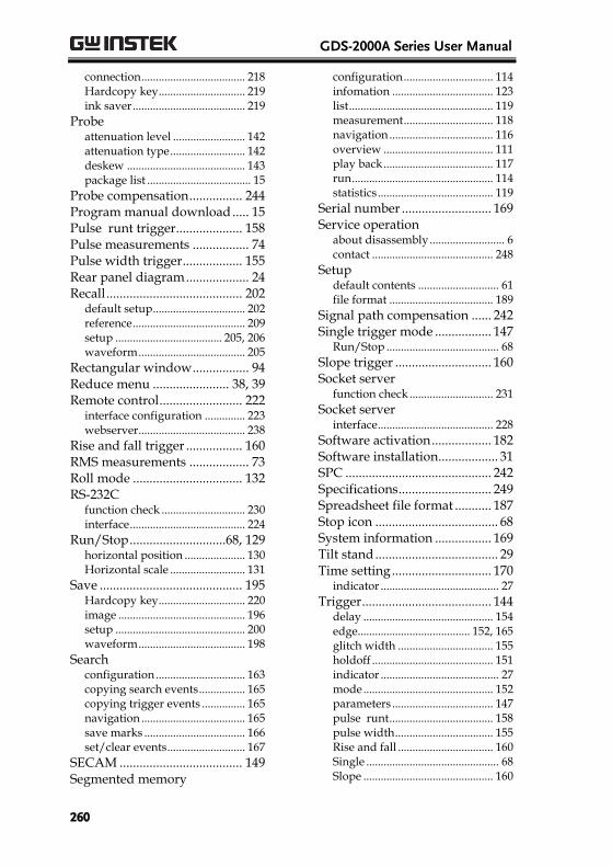
GDS-2000A Series User Manual
260
connection .................................... 218 Hardcopy key .............................. 219 ink saver ....................................... 219
Probe attenuation level ......................... 142 attenuation type .......................... 142 deskew ......................................... 143 package list .................................... 15
Probe compensation ................ 244 Program manual download ..... 15 Pulse runt trigger .................... 158 Pulse measurements ................. 74 Pulse width trigger .................. 155 Rear panel diagram ................... 24 Recall ......................................... 202
default setup ................................ 202 reference ....................................... 209 setup ..................................... 205, 206 waveform ..................................... 205
Rectangular window ................. 94 Reduce menu ....................... 38, 39 Remote control ......................... 222
interface configuration .............. 223 webserver ..................................... 238
Rise and fall trigger ................. 160 RMS measurements .................. 73 Roll mode ................................. 132 RS-232C
function check ............................. 230 interface ........................................ 224
Run/Stop .............................68, 129 horizontal position ..................... 130 Horizontal scale .......................... 131
Save ........................................... 195 Hardcopy key .............................. 220 image ............................................ 196 setup ............................................. 200 waveform ..................................... 198
Search configuration ............................... 163 copying search events ................ 165 copying trigger events ............... 165 navigation .................................... 165 save marks ................................... 166 set/clear events ........................... 167
SECAM ..................................... 149 Segmented memory
configuration ............................... 114 infomation ................................... 123 list .................................................. 119 measurement ............................... 118 navigation .................................... 116 overview ...................................... 111 play back ...................................... 117 run ................................................. 114 statistics ........................................ 119
Serial number ........................... 169 Service operation
about disassembly .......................... 6 contact .......................................... 248
Setup default contents ............................ 61 file format .................................... 189
Signal path compensation ...... 242 Single trigger mode ................. 147
Run/Stop ....................................... 68
Slope trigger ............................. 160 Socket server
function check ............................. 231
Socket server interface ........................................ 228
Software activation .................. 182 Software installation .................. 31 SPC ............................................ 242 Specifications ............................ 249 Spreadsheet file format ........... 187 Stop icon ..................................... 68 System information ................. 169 Tilt stand ..................................... 29 Time setting .............................. 170
indicator ......................................... 27
Trigger ....................................... 144 delay ............................................. 154 edge....................................... 152, 165 glitch width ................................. 155 holdoff .......................................... 151 indicator ......................................... 27 mode ............................................. 152 parameters ................................... 147 pulse runt .................................... 158 pulse width .................................. 155 Rise and fall ................................. 160 Single .............................................. 68 Slope ............................................. 160
INDEX
261
specification ................................. 250 status indicator ............................. 28 Timeout ........................................ 161
overview ................................. 150 video ............................................. 157
UK power cord ............................. 9 Uninstall applications ............. 176 Uninstall optional software .... 183 USB
driver download ........................... 15 function check ............................. 230 remote control interface ............ 223
Vectors....................................... 124 Vertical ...................................... 137
accuracy calibration ................... 243 basic operation .............................. 71 position ......................................... 137 scale .............................................. 137
specification ................................. 250
Video trigger ............................. 157 Warning symbol ........................... 5 Waveform
CSV file contents ......................... 188 file contents ................................. 187 how to recall ................................ 205 how to save .................................. 198 invert waveform ......................... 139 play/pause key ........................... 135 roll mode ...................................... 132 zoom mode .................................. 133
Waveform color .......................... 26 Waveform file format .............. 186 XY
specification ................................. 251
Zoom waveform ....................... 133