Embed Size (px)
Citation preview

Form 4D Microprocessor-based pole-mount recloser control installation and operation instructions
Figure 1. Form 4D microprocessor-based pole-mount recloser control
Applicable to the following serial numbers:
Type KME4DPA control: serial number CP571231477 and above, applies to Form 4D control for use with W, VS, and auxiliary-powered NOVA reclosers.
Type KME4DPB control: serial number CP571231527 and above, applies to control-powered NOVA Form 4D control for use with control-powered reclosers.
COOPER POWERSERIES
ReclosersMN280049EN
Effective September 2017 Supersedes January 2012 (S280-104-1)

DISCLAIMER OF WARRANTIES AND LIMITATION OF LIABILITY
The information, recommendations, descriptions and safety notations in this document are based on Eaton Corporation’s (“Eaton”) experience and judgment and may not cover all contingencies. If further information is required, an Eaton sales office should be consulted. Sale of the product shown in this literature is subject to the terms and conditions outlined in appropriate Eaton selling policies or other contractual agreement between Eaton and the purchaser.
THERE ARE NO UNDERSTANDINGS, AGREEMENTS, WARRANTIES, EXPRESSED OR IMPLIED, INCLUDING WARRANTIES OF FITNESS FOR A PARTICULAR PURPOSE OR MERCHANTABILITY, OTHER THAN THOSE SPECIFICALLY SET OUT IN ANY EXISTING CONTRACT BETWEEN THE PARTIES. ANY SUCH CONTRACT STATES THE ENTIRE OBLIGATION OF EATON. THE CONTENTS OF THIS DOCUMENT SHALL NOT BECOME PART OF OR MODIFY ANY CONTRACT BETWEEN THE PARTIES.
In no event will Eaton be responsible to the purchaser or user in contract, in tort (including negligence), strict liability or other-wise for any special, indirect, incidental or consequential damage or loss whatsoever, including but not limited to damage or loss of use of equipment, plant or power system, cost of capital, loss of power, additional expenses in the use of existing power facilities, or claims against the purchaser or user by its customers resulting from the use of the information, recommendations and descriptions contained herein. The information contained in this manual is subject to change without notice.
ioperation inStrUCtionS MN280049EN September 2017

Contents
DISCLAIMER OF WARRANTIES AND LIMITATION OF LIABILITY . . . . . . . . . . . . . . . . . . . . . . . . . . . . . . . . . . . . I
SAFETY INFORMATION . . . . . . . . . . . . . . . . . . . . . . . . . . . . . . . . . . . . . . . . . . . . . . . . . . . . . . . . . . . . . . . . . . . Iv
PRODuCT INFORMATION . . . . . . . . . . . . . . . . . . . . . . . . . . . . . . . . . . . . . . . . . . . . . . . . . . . . . . . . . . . . . . . . . . 1Introduction . . . . . . . . . . . . . . . . . . . . . . . . . . . . . . . . . . . . . . . . . . . . . . . . . . . . . . . . . . . . . . . . . . . . . . . . . . . . . . . . . . 1
ANSI and quality standards . . . . . . . . . . . . . . . . . . . . . . . . . . . . . . . . . . . . . . . . . . . . . . . . . . . . . . . . . . . . . . . . . . . . . . 1
Acceptance and initial inspection . . . . . . . . . . . . . . . . . . . . . . . . . . . . . . . . . . . . . . . . . . . . . . . . . . . . . . . . . . . . . . . . . . 1
Handling and storage . . . . . . . . . . . . . . . . . . . . . . . . . . . . . . . . . . . . . . . . . . . . . . . . . . . . . . . . . . . . . . . . . . . . . . . . . . . 1
Control power . . . . . . . . . . . . . . . . . . . . . . . . . . . . . . . . . . . . . . . . . . . . . . . . . . . . . . . . . . . . . . . . . . . . . . . . . . . . . . . . . 2
Battery replacement and disposal . . . . . . . . . . . . . . . . . . . . . . . . . . . . . . . . . . . . . . . . . . . . . . . . . . . . . . . . . . . . . . . . . 2
Operation upon loss of AC power . . . . . . . . . . . . . . . . . . . . . . . . . . . . . . . . . . . . . . . . . . . . . . . . . . . . . . . . . . . . . . . . . 2
Battery monitoring . . . . . . . . . . . . . . . . . . . . . . . . . . . . . . . . . . . . . . . . . . . . . . . . . . . . . . . . . . . . . . . . . . . . . . . . . . . . . 2
FORM 4D RECLOSER CONTROL DESCRIPTION . . . . . . . . . . . . . . . . . . . . . . . . . . . . . . . . . . . . . . . . . . . . . . . . 2Description . . . . . . . . . . . . . . . . . . . . . . . . . . . . . . . . . . . . . . . . . . . . . . . . . . . . . . . . . . . . . . . . . . . . . . . . . . . . . . . . . . . 2
Theory of operation . . . . . . . . . . . . . . . . . . . . . . . . . . . . . . . . . . . . . . . . . . . . . . . . . . . . . . . . . . . . . . . . . . . . . . . . . . . . 3
Control front panel . . . . . . . . . . . . . . . . . . . . . . . . . . . . . . . . . . . . . . . . . . . . . . . . . . . . . . . . . . . . . . . . . . . . . . . . . . . . . 4
Control features . . . . . . . . . . . . . . . . . . . . . . . . . . . . . . . . . . . . . . . . . . . . . . . . . . . . . . . . . . . . . . . . . . . . . . . . . . . . . . . 9
Communications . . . . . . . . . . . . . . . . . . . . . . . . . . . . . . . . . . . . . . . . . . . . . . . . . . . . . . . . . . . . . . . . . . . . . . . . . . . . . 11
Control information . . . . . . . . . . . . . . . . . . . . . . . . . . . . . . . . . . . . . . . . . . . . . . . . . . . . . . . . . . . . . . . . . . . . . . . . . . . . 12
Control side panel . . . . . . . . . . . . . . . . . . . . . . . . . . . . . . . . . . . . . . . . . . . . . . . . . . . . . . . . . . . . . . . . . . . . . . . . . . . . 12
INSTALLATION PROCEDuRE . . . . . . . . . . . . . . . . . . . . . . . . . . . . . . . . . . . . . . . . . . . . . . . . . . . . . . . . . . . . . . . 12Initial programming prior to installation . . . . . . . . . . . . . . . . . . . . . . . . . . . . . . . . . . . . . . . . . . . . . . . . . . . . . . . . . . . . 12
Control/Recloser compatibility . . . . . . . . . . . . . . . . . . . . . . . . . . . . . . . . . . . . . . . . . . . . . . . . . . . . . . . . . . . . . . . . . . . 13
Duty cycle monitor . . . . . . . . . . . . . . . . . . . . . . . . . . . . . . . . . . . . . . . . . . . . . . . . . . . . . . . . . . . . . . . . . . . . . . . . . . . . 13
Mounting the control . . . . . . . . . . . . . . . . . . . . . . . . . . . . . . . . . . . . . . . . . . . . . . . . . . . . . . . . . . . . . . . . . . . . . . . . . . 14
Control cable . . . . . . . . . . . . . . . . . . . . . . . . . . . . . . . . . . . . . . . . . . . . . . . . . . . . . . . . . . . . . . . . . . . . . . . . . . . . . . . . 15
Grounding the control . . . . . . . . . . . . . . . . . . . . . . . . . . . . . . . . . . . . . . . . . . . . . . . . . . . . . . . . . . . . . . . . . . . . . . . . . 15
Customer connections for AC power . . . . . . . . . . . . . . . . . . . . . . . . . . . . . . . . . . . . . . . . . . . . . . . . . . . . . . . . . . . . . . 17
Customer connections for contact I/O module . . . . . . . . . . . . . . . . . . . . . . . . . . . . . . . . . . . . . . . . . . . . . . . . . . . . . . 24
Before placing control and recloser into service . . . . . . . . . . . . . . . . . . . . . . . . . . . . . . . . . . . . . . . . . . . . . . . . . . . . . 26
ACCESSORIES . . . . . . . . . . . . . . . . . . . . . . . . . . . . . . . . . . . . . . . . . . . . . . . . . . . . . . . . . . . . . . . . . . . . . . . . . . 28Low voltage closing . . . . . . . . . . . . . . . . . . . . . . . . . . . . . . . . . . . . . . . . . . . . . . . . . . . . . . . . . . . . . . . . . . . . . . . . . . . 28
Cabinet ordering accessories . . . . . . . . . . . . . . . . . . . . . . . . . . . . . . . . . . . . . . . . . . . . . . . . . . . . . . . . . . . . . . . . . . . . 28
Incoming power receptacles . . . . . . . . . . . . . . . . . . . . . . . . . . . . . . . . . . . . . . . . . . . . . . . . . . . . . . . . . . . . . . . . . . . . 28
Internal voltage sensing . . . . . . . . . . . . . . . . . . . . . . . . . . . . . . . . . . . . . . . . . . . . . . . . . . . . . . . . . . . . . . . . . . . . . . . . 28
Cable locking sleeves . . . . . . . . . . . . . . . . . . . . . . . . . . . . . . . . . . . . . . . . . . . . . . . . . . . . . . . . . . . . . . . . . . . . . . . . . . 32
BCT Terminal blocks accessory . . . . . . . . . . . . . . . . . . . . . . . . . . . . . . . . . . . . . . . . . . . . . . . . . . . . . . . . . . . . . . . . . . . 32
Auxiliary terminal block accessory . . . . . . . . . . . . . . . . . . . . . . . . . . . . . . . . . . . . . . . . . . . . . . . . . . . . . . . . . . . . . . . . 32
120 VAC GFI Duplex outlet . . . . . . . . . . . . . . . . . . . . . . . . . . . . . . . . . . . . . . . . . . . . . . . . . . . . . . . . . . . . . . . . . . . . . . 32
Automation accessory packages . . . . . . . . . . . . . . . . . . . . . . . . . . . . . . . . . . . . . . . . . . . . . . . . . . . . . . . . . . . . . . . . . 32
Communication board accessories . . . . . . . . . . . . . . . . . . . . . . . . . . . . . . . . . . . . . . . . . . . . . . . . . . . . . . . . . . . . . . . 33
iioperation inStrUCtionS MN280049EN September 2017

Contents (continued)
TESTINg . . . . . . . . . . . . . . . . . . . . . . . . . . . . . . . . . . . . . . . . . . . . . . . . . . . . . . . . . . . . . . . . . . . . . . . . . . . . . . . 36Testing an installed control . . . . . . . . . . . . . . . . . . . . . . . . . . . . . . . . . . . . . . . . . . . . . . . . . . . . . . . . . . . . . . . . . . . . . . 36
Remove the control from service . . . . . . . . . . . . . . . . . . . . . . . . . . . . . . . . . . . . . . . . . . . . . . . . . . . . . . . . . . . . . . . . . 37
Preliminary testing with No AC Available . . . . . . . . . . . . . . . . . . . . . . . . . . . . . . . . . . . . . . . . . . . . . . . . . . . . . . . . . . . 38
Testing with type MET Tester . . . . . . . . . . . . . . . . . . . . . . . . . . . . . . . . . . . . . . . . . . . . . . . . . . . . . . . . . . . . . . . . . . . . 38
Closing the recloser during testing . . . . . . . . . . . . . . . . . . . . . . . . . . . . . . . . . . . . . . . . . . . . . . . . . . . . . . . . . . . . . . . 39
Battery test and charging procedures . . . . . . . . . . . . . . . . . . . . . . . . . . . . . . . . . . . . . . . . . . . . . . . . . . . . . . . . . . . . . 42
Return the control to service . . . . . . . . . . . . . . . . . . . . . . . . . . . . . . . . . . . . . . . . . . . . . . . . . . . . . . . . . . . . . . . . . . . . 44
ADDITIONAL PROCEDuRES . . . . . . . . . . . . . . . . . . . . . . . . . . . . . . . . . . . . . . . . . . . . . . . . . . . . . . . . . . . . . . . 44Using removable inserts . . . . . . . . . . . . . . . . . . . . . . . . . . . . . . . . . . . . . . . . . . . . . . . . . . . . . . . . . . . . . . . . . . . . . . . . 44
Remove existing module . . . . . . . . . . . . . . . . . . . . . . . . . . . . . . . . . . . . . . . . . . . . . . . . . . . . . . . . . . . . . . . . . . . . . . . 45
Install module . . . . . . . . . . . . . . . . . . . . . . . . . . . . . . . . . . . . . . . . . . . . . . . . . . . . . . . . . . . . . . . . . . . . . . . . . . . . . . . . 46
Additional information . . . . . . . . . . . . . . . . . . . . . . . . . . . . . . . . . . . . . . . . . . . . . . . . . . . . . . . . . . . . . . . . . . . . . . . . . . 46
Replacement kits . . . . . . . . . . . . . . . . . . . . . . . . . . . . . . . . . . . . . . . . . . . . . . . . . . . . . . . . . . . . . . . . . . . . . . . . . . . . . 46
Factory-Authorized service centers . . . . . . . . . . . . . . . . . . . . . . . . . . . . . . . . . . . . . . . . . . . . . . . . . . . . . . . . . . . . . . . 46
iii operation inStrUCtionS MN280049EN September 2017

The instructions in this manual are not intended as a substitute for proper training or adequate experience in the safe operation of the equipment described. Only competent technicians who are familiar with this equipment should install, operate, and service it.
A competent technician has these qualifications:
• Is thoroughly familiar with these instructions.
• Is trained in industry-accepted high and low-voltage safe operating practices and procedures.
• Is trained and authorized to energize, de-energize, clear, and ground power distribution equipment.
• Is trained in the care and use of protective equipment such as flash clothing, safety glasses, face shield, hard hat, rubber gloves, hotstick, etc.
Following is important safety information. For safe installation and operation of this equipment, be sure to read and understand all cautions and warnings.
Safety instructionsFollowing are general caution and warning statements that apply to this equipment. Additional statements, related to specific tasks and procedures, are located throughout the manual.
Safety for lifeEaton’s Cooper Power series products meet or exceed all applicable industry standards relating to product safety. We actively promote safe practices in the use and maintenance of our products through our service literature, instructional training programs, and the continuous efforts of all Eaton employees involved in product design, manufacture, marketing, and service.
We strongly urge that you always follow all locally approved safety procedures and safety instructions when working around high voltage lines and equipment and support our “Safety For Life” mission.
Safety information
DANgERHazardous voltage. Contact with hazardous voltage will cause death or severe personal injury. Follow all locally approved safety procedures when working around high- and low-voltage lines and equipment. g103.3
WARNINg Before installing, operating, maintaining, or testing this equipment, carefully read and understand the contents of this manual. Improper operation, handling or maintenance can result in death, severe personal injury, and equipment damage. g101.0
WARNINg This equipment is not intended to protect human life. Follow all locally approved procedures and safety practices when installing or operating this equipment. Failure to comply may result in death, severe personal injury and equipment damage. g102.1
WARNINg Before installing, operating, maintaining, or testing this Power distribution and transmission equipment must be properly selected for the intended application. It must be installed and serviced by competent personnel who have been trained and understand proper safety procedures. These instructions are written for such personnel and are not a substitute for adequate training and experience in safety procedures. Failure to properly select, install or maintain power distribution and transmission equipment can result in death, severe personal injury, and equipment damage. g122.3
This manual may contain four types of hazard statements:
DANgER Indicates an imminently hazardous situation which, if not avoided, will result in death or serious injury.
WARNINg Indicates a potentially hazardous situation which, if not avoided, could result in death or serious injury.
CAuTION Indicates a potentially hazardous situation which, if not avoided, may result in minor or moderate injury.
CAuTIONIndicates a potentially hazardous situation which, if not avoided, may result in equipment damage only.
Hazard Statement Definitions
!SAFETYFOR LIFE
!SAFETYFOR LIFE
ivoperation inStrUCtionS MN280049EN September 2017

Product information
IntroductionService Information MN280049EN provides installation and operation instructions for the Form 4D pole-mount recloser control.
Refer to Service Information S280-104-2 Form 4D Microprocessor-Based Recloser Control Programming Guide and S280-104-3 Form 4D Control Communications Information for additional information.
Read this manual firstRead and understand the contents of this manual and follow all locally approved procedures and safety practices before installing or operating this equipment.
Additional informationThese instructions cannot cover all details or vari ations in the equipment, procedures, or process described, nor provide directions for meeting every possible contin gency during installation, operation, or maintenance. When additional information is desired to satisfy a problem not cov ered sufficiently for the user’s purpose, contact your Eaton representative.
ANSI StandardsEaton’s Cooper Power series reclosers are designed and tested in accordance with applicable sections of the following ANSI standards: C37.60 and C37.85 and ANSI Guide C37.61.
Quality standardsISO 9001 Certified Quality Management System
Acceptance and initial inspectionEach Form 4D recloser control is completely assembled, tested, and inspected at the factory. It is carefully calibrated, adjusted and in good condition when accepted by the carrier for shipment.
Upon receipt, inspect the carton for signs of damage. Unpack the control and inspect it thoroughly for damage incurred during shipment. If damage is discovered, file a claim with the carrier immediately.
Handling and storageBe careful during handling and storage of the control to minimize the possibility of damage. If the control is to be stored for any length of time prior to installation, provide a clean, dry storage area. If storage is in a humid atmosphere, make provisions to keep the control circuitry energized.
otee:N To energize the control, apply AC power to the AC supply input terminal block located in the lower right hand corner of the back panel of the control. Refer to the Customer Connections for AC Power section in this manual.
otee:N When opened, both the cabinet door and the inside swing panel door lock into the open position. Lift the door or swing panel up to raise the hinge out of the locking position prior to closing the inside swing panel door or the cabinet door.
Control battery storage and chargingThe 24 VDC control battery in the Form 4D recloser control is shipped in a charged state that is ready for use.
IMPORTANTTo maintain sufficient charge to operate the control and prevent battery cell damage, the sealed lead-acid batteries should be charged after no more than three months of storage.
Temperature has an effect on battery life. Sealed lead acid batteries should be stored, fully charged, at room temperature. Avoid storing lead acid batteries at temperatures exceeding 47°C (117°F), as damage can result in approximately one month.
DANgERHazardous voltage. Do not connect potential transformer low-voltage secondaries to the control through cables or other wiring until the unit is installed in the field. Transformer high-voltage primary windings will become live when 120/240v AC is applied to the control from an alternate source if the transformer secondary is connected. Failure to comply may result in severe personal injury or death. T371.2
WARNINgHazardous voltage. Before applying power to the control, confirm that male pins of the input power receptacle are electrically insulated to prevent unintentional contact with 120/240v AC voltage. Failure to do so may result in severe personal injury or death. T372.1
To keep the battery charged, energize the control with AC power applied to the user AC supply input connector block TB1. See Customer Connections for AC Power. In addition, if power to the control is not possible a separate portable charger accessory is available. Catalog Number KA43ME7001 provides a 120 Volt battery charger to power individual batteries.
IMPORTANTConnect the control battery before AC power is connected to the control’s AC supply Input Terminal Block. The battery must be disconnected prior to shipping or storing the control.
otee:N When shipped from the factory the battery will be in the same carton as the control. The battery leads will be taped to the battery casing. Connect the battery plugs into the mating connectors to complete the battery circuit.
1operation inStrUCtionS MN280049EN September 2017
Form 4D Microprocessor-based pole-mount recloser control installation and operation instructions

IMPORTANTTo avoid damage to the wiring or batteries, do not transport the control with the batteries installed.
Control powerThe control voltage is auto-ranging from 96 to 265 VAC.
Battery replacement and disposalThe 24 VDC control battery has a life expectancy of four years. It is recommended that the battery be replaced after four years or if the battery fails a battery test (after sufficient recharge time) – whichever occurs first.
otee:N Battery life is decreased at higher temperatures.
Dispose expired batteries in an environmentally responsible manner. Consult local regulations for proper battery disposal.
Operation upon loss of AC powerThe control can be equipped with either an 8 Amp-Hour or 13 Amp-Hour 24 VDC lead acid battery for operation upon loss of AC power. The control maintains full operation from the battery for a period of time dependent upon the battery size:
8 Amp-Hour – 24 hour maximum (20°C)
13 Amp-Hour – 36 hour maximum (20°C)
The control continuously monitors the battery voltage. To prevent battery damage, the control shuts down automatically upon detection of low battery voltage (below 21 VDC) for 60 seconds. Refer to Testing section for additional battery monitoring information.
Control programming settings and parameters – including sequence of events recorder and data profiler – are stored in non-volatile memory and retained upon loss of control power. The time/date clock will continue to operate for approximately four days after loss of control power (battery and AC power). After this time period elapses, the control time will be set to 12:00 AM, Jan. 1, 1970.
The control clock may require resetting if the operating power has been disconnected for more than four days. Refer to Service Information S280-104-2 Form 4D Microprocessor-Based Recloser Control Programming Guide for information on setting the control clock.
otee:N When AC power is present, the control will operate regardless of back-up battery presence.
If B-phase (or the user-indicated phase) loses AC power and the applicable alarm is configured by the user, the ALARM red indicator LED will illuminate and the ALARM log on the LCD Display will indicate NO AC PRESENT.
IMPORTANTIf the control shuts down due to low battery voltage before AC power is restored, and the connected energized recloser is CLOSED, no operations are possible until AC power is restored or the battery is replaced and connected.
A control that has shut down due to low battery voltage before AC power is restored will have a blank LCD display (no text message shown).
Battery MonitoringBattery monitoring occurs whether AC power is being supplied or not.
Battery monitoring occurs every 1 – 2 seconds
This Battery monitoring does not take place during a battery test.
The BATTERY LED will illuminate for the following conditions:
Battery voltage rises above 37 volts.
Battery voltage drops below 22 volts for 60 seconds.
Form 4D control is operating on battery power only and battery voltage drops below 21 volts for 60 seconds. At this time, the battery disconnect alarm is issued.
Battery test failure.
If the Form 4D control is still operating on battery power and the battery voltage is still below 21 volts for 60 seconds after a battery disconnect alarm has been issued, the battery is disconnected from powering the control and the control shuts down.
The BATTERY LED will turn off if the battery voltage is below 37 volts and above 22 volts for 30 seconds.
Form 4D Recloser control description
DescriptionThe Form 4D pole-mount microprocessor-based recloser control includes extensive system protection functionality, including phase and ground overcurrent protection, over/underfrequency and voltage protection, sensitive ground fault, and sync check.
Analysis tools include sequence of events recording, TCC EditorTM II, and data profiler.
Metering functions include demand and instantaneous current on a per-phase basis, instantaneous voltage and power factor on a per-phase basis, and power (real, reactive, apparent) on a per phase or total basis. Symmetrical components for both voltage and current are displayed along with kilowatt-hours for energy metering. Harmonics from the 2nd to the 15th harmonic are also included.
2 operation inStrUCtionS MN280049EN September 2017
Form 4D Microprocessor-based pole-mount recloser control installation and operation instructions
The front panel LCD display is used to configure the operating settings for the control. It is also used to display metering, counter information, control parameters, alarms, and sequence of events.
Control parameters can also be programmed via a personal computer connected to the control through the front panel USB port or the communications boards. Control programming, interrogation, and operations are performed with Form 4D ProView NXGTM interface software on a computer.
ProView interface program software includes additional functions used to create and graphically display Time Current Curves, configurable sequence of events and alarm data, and selectable communication points for serial (DNP, Modbus, IEC 61850, 2179, IEC 60870-5-101) and Ethernet communication (DNP3 IP, IEC 60870-5-104).
The control operates on 50 and 60 Hz systems.
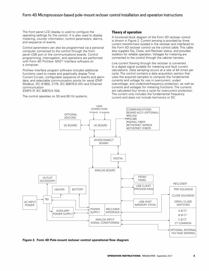
Theory of operationA functional block diagram of the Form 4D recloser control is shown in Figure 2. Current sensing is provided by three current transformers located in the recloser and interfaced to the Form 4D recloser control via the control cable. This cable also supplies Trip, Close, and Recloser status, and provides isolation for reliable operation. Voltages for metering are connected to the control through the cabinet harness.
Line current flowing through the recloser is converted to a digital signal suitable for metering and fault current calculations. Data sampling occurs at a rate of 64 times per cycle. The control contains a data acquisition section that uses the acquired samples to compute the fundamental currents and voltage for use in overcurrent, under/overvoltage, and under/overfrequency protection, as well as currents and voltages for metering functions. The currents are calculated four times a cycle for overcurrent protection. The current only includes the fundamental frequency current and does not include harmonics or DC.
TRIP SOLENOID
CLOSE SOLENOID
A Ø CT
B Ø CT
C Ø CT
OPEN / CLOSESWITCHES
CT COMMON
RECLOSER
AC INPUTPOWER
BATTERY
INTERCONNECTBOARD
I/O BOARD
FRONTPANEL
USB CLIENT(PROVIEW NXG)
USERCONNECTIONS COMMUNICATIONS
BOARD ACCY (OPTIONAL)•RS-232•RS-485•SERIAL FIBER•ETHERNET (WIRED)•ETHERNET (FIBER)
OPTIONAL INTERNALVOLTAGE SENSING
4 inputs 4 outputs
USB HOST(MEMORY STICK)
DIGITAL
ANALOG BOARD
POWERSUPPLY
RECLOSERINTERFACE
ANALOG INPUTSIGNAL CONDITIONING
TB1
OUTLETACCESSORY
I/O BOARD
OPTIONALADD-ONS
AUXILIARYPOWER SUPPLY
HEATER
Figure 2. Form 4D Pole-mount recloser control operational flow diagram
3operation inStrUCtionS MN280049EN September 2017
Form 4D Microprocessor-based pole-mount recloser control installation and operation instructions

When the phase or ground current exceeds its programmed minimum-trip value and associated time-current-curve (TCC) timing, the control initiates the programmed sequence of recloser tripping and reclosing operations. If the fault is temporary, the control ceases to command recloser operations after a successful reclose, and the control resets to the start of its operating sequence after a preset time delay. If the fault is permanent, the control performs its complete programmed sequence of reclose commands and locks out with the recloser open. Once locked out, the control must be closed via the operator panel or SCADA communications. This resets the control to the start of the operating sequence.
The following chain of events occurs for an operating sequence of two trips to lockout (one trip on TCC1, one trip on TCC2):
1. The overcurrent signal is integrated with time on the selected curve for the first trip operation (TCC1) to produce the signal which energizes the trip circuit.
2. Energizing the trip circuit connects the supply to the trip solenoid to open the recloser.
3. Upon opening, the control starts timing on the first reclosing interval-delay time.
4. Upon expiration of this reclosing interval-delay, a closing signal is issued from the control, closing the recloser, and selecting the time-current characteristics for the second trip operation (TCC2).
5. If current remains above the minimum-trip level, the recloser will trip on TCC2 and lockout the recloser.
Control front panelThe Form 4D control front panel is illustrated in Figure 3.
The front panel is separated into two clearly identified, color-coded sections:
Programming Panel: The top portion of the front panel is used for programming the control and providing LED status indication.
Operating Panel: The lower portion of the front operating panel is used for operating the control and recloser.
The control includes a Power Save feature that will turn off the LEDs and backlit LCD display after 15 minutes of inactivity at the front panel (no buttons pressed). The CONTROL OK and HOT LINE TAG LEDs are not affected by the power save mode. Pressing any key on the front panel will turn the LCD backlight on and restore all LEDs to their current on/off states.
The control includes a Reset Menu feature that will cause the LCD display to revert to the root menu after 15 minutes of inactivity.
Figure 3. Form 4D Pole-mount control front panel
Programming panel
CAuTIONEquipment misoperation. use of the control front panel HMI may result in several combinations of settings, configurations, and customizations. The user must ensure that a proper combination is created and downloaded for the appropriate device application. G163.0
The Programming panel has the following sections:
LCD display (Figure 4)The LCD display is a 4-line, 20-character display. The LCD display panel contrast is field-adjustable to allow for various mounting heights and applications. Press the FUNC key and UP or DOWN arrow simultaneously to increase or decrease contrast.
The keypad functionality is summarized as follows.
The (up) key can be used for the following tasks:
Scroll to the next item up on the current Menu level.
If already at the first item of the current Menu level, return to the last item of the current Menu.
4 operation inStrUCtionS MN280049EN September 2017
Form 4D Microprocessor-based pole-mount recloser control installation and operation instructions

DATA PORTS
ENTER
EDITESC
PHASE FAULT
A B C
GROUND FAULT
ABOVE MIN TRIP
LOCKOUT
OPEN
CLOSED
VOLTAGE TRIP
FREQUENCY TRIP
SENSITIVE GND
A B C
X Y Z
PHASE VOLTAGE
ALARM
BATTERY
AC POWER
CONTROL OK
ALTPROFILE 1
GND TRIPBLOCKED
NONRECLOSE
SUPER-VISORY
OFF
HOT LINETAGTRIP
OFF(LOCKOUT)
CLOSE
Figure 4. LCD Display and keypad functionality
When editing a selectable option parameter, scroll up to the next available option.
Change the numerical value from positive to negative or vice versa.
Change the case of a letter when editing Passwords.
The (down) key can be used to complete the following tasks:
Scroll to the next item down on current Menu level.
If scrolled past the last line of the current Menu level, return to the first line of the current Menu.
When editing a Selectable Option Parameter, scroll down to the next available option.
Change the numerical value from positive to negative or vice versa.
Change the case of a letter when editing Passwords.
The (left) key is used to go up one Menu level.
The (left) key is used to move left when editing parameters.
The (right) key is used to go down one Menu level.
The (right) key is used to move right when editing parameters.
The ESC (escape) key is used for the following tasks:
Go up one Menu level.
Cancel Edit mode when editing settings without changing the value.
The ENTER key is used for the following tasks:
Go down one Menu level.
Confirm settings change in the Edit mode.
Execute function codes.
Confirm resetting the Resettable Parameters.
Confirm passwords
The EDIT key is used for the following tasks:
Enter the Edit mode to make a change.
Enter the Reset mode to reset the Resettable Parameter.
The FUNC (function) key is used to enter the function code mode.
The ALPHANUMERIC keys are used for the following tasks:
Edit scalar parameters.
Enter function codes.
Enter security codes.
Function as shortcuts to Menu items.
The SYM key is used to enter special characters.
Status indicator LEDsThe status indicator LEDs (Figures 5 and 6) in the Programming section of the Operator Panel give instant information on the control and recloser status:
This information is indicated on the left side of the control: (Figure 5):
A PHASE FAULT
B PHASE FAULT
C PHASE FAULT
GROUND FAULT
SENSITIVE GND
These LED indicators illuminate when the control issues an overcurrent trip signal while the respective phase current or ground current exceeds the minimum pickup value.
FREQUENCY TRIP: This LED illuminates to indicate the recloser tripped due to an under or overfrequency condition.
VOLTAGE TRIP: This LED illuminates to indicate the recloser tripped due to an under or overvoltage condition.
5operation inStrUCtionS MN280049EN September 2017
Form 4D Microprocessor-based pole-mount recloser control installation and operation instructions
DATA PORTS
ENTER
EDITESC
PHASE FAULT
A B C
GROUND FAULT
ABOVE MIN TRIP
LOCKOUT
OPEN
CLOSED
VOLTAGE TRIP
FREQUENCY TRIP
SENSITIVE GND
A B C
X Y Z
PHASE VOLTAGE
ALARM
BATTERY
AC POWER
CONTROL OK
ALTPROFILE 1
GND TRIPBLOCKED
NONRECLOSE
SUPER-VISORY
OFF
HOT LINETAGTRIP
OFF(LOCKOUT)
CLOSE
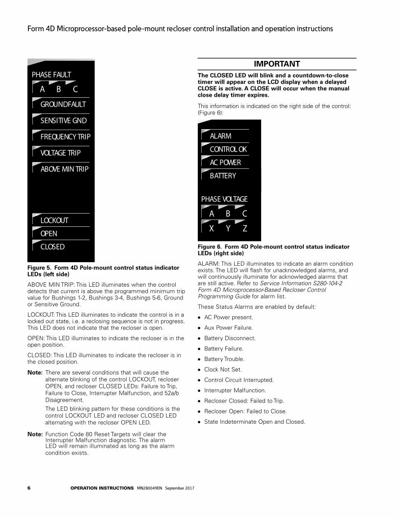
Figure 5. Form 4D Pole-mount control status indicator LEDs (left side)
ABOVE MIN TRIP: This LED illuminates when the control detects that current is above the programmed minimum trip value for Bushings 1-2, Bushings 3-4, Bushings 5-6, Ground or Sensitive Ground.
LOCKOUT: This LED illuminates to indicate the control is in a locked out state, i.e. a reclosing sequence is not in progress. This LED does not indicate that the recloser is open.
OPEN: This LED illuminates to indicate the recloser is in the open position.
CLOSED: This LED illuminates to indicate the recloser is in the closed position.
otee:N There are several conditions that will cause the alternate blinking of the control LOCKOUT, recloser OPEN, and recloser CLOSED LEDs: Failure to Trip, Failure to Close, Interrupter Malfunction, and 52a/b Disagreement.
The LED blinking pattern for these conditions is the control LOCKOUT LED and recloser CLOSED LED alternating with the recloser OPEN LED.
otee:N Function Code 80 Reset Targets will clear the Interrupter Malfunction diagnostic. The alarm LED will remain illuminated as long as the alarm condition exists.
IMPORTANTThe CLOSED LED will blink and a countdown-to-close timer will appear on the LCD display when a delayed CLOSE is active. A CLOSE will occur when the manual close delay timer expires.
This information is indicated on the right side of the control: (Figure 6):
DATA PORTS
ENTER
EDITESC
PHASE FAULT
A B C
GROUND FAULT
ABOVE MIN TRIP
LOCKOUT
OPEN
CLOSED
VOLTAGE TRIP
FREQUENCY TRIP
SENSITIVE GND
A B C
X Y Z
PHASE VOLTAGE
ALARM
BATTERY
AC POWER
CONTROL OK
ALTPROFILE 1
GND TRIPBLOCKED
NONRECLOSE
SUPER-VISORY
OFF
HOT LINETAGTRIP
OFF(LOCKOUT)
CLOSE
Figure 6. Form 4D Pole-mount control status indicator LEDs (right side)
ALARM: This LED illuminates to indicate an alarm condition exists. The LED will flash for unacknowledged alarms, and will continuously illuminate for acknowledged alarms that are still active. Refer to Service Information S280-104-2 Form 4D Microprocessor-Based Recloser Control Programming Guide for alarm list.
These Status Alarms are enabled by default:
AC Power present.
Aux Power Failure.
Battery Disconnect.
Battery Failure.
Battery Trouble.
Clock Not Set.
Control Circuit Interrupted.
Interrupter Malfunction.
Recloser Closed: Failed to Trip.
Recloser Open: Failed to Close.
State Indeterminate Open and Closed.
6 operation inStrUCtionS MN280049EN September 2017
Form 4D Microprocessor-based pole-mount recloser control installation and operation instructions

IMPORTANTTo enable or disable specific alarms, use the Proview NXG software to configure the alarms. Refer to Section 5e: Alarms in Service Information S280-104-2 Form 4D Microprocessor-Based Recloser Control Programming Guide. If alarms are not configured, the ALARM LED will not illuminate.
CAuTIONLoss of protection. Reconfigure the user settings. When the CONTROL OK LED is flashing, control protection is disabled. user protection profile settings must be reconfigured to enable protection. Loss of protection can result in personal injury and equipment damage. T360.1
CONTROL OK: This indicator illuminates to indicate that the control passed self-diagnostics and is capable of normal operation.
otee:N A flashing CONTROL OK LED indicates a problem with user settings. Default settings will be displayed under these circumstances, but protection has been disabled. User protection profile settings must be reconfigured to enable protection.
When the CONTROL OK LED is flashing, the following message appears on the LCD display upon power-up:
Protection Disabled. Change Protection Settings. Press ESC to Clear Message.
As soon as the HMI goes into power save mode (inactivity for 15 minutes) the message will no longer display on the LCD, but the CONTROL OK LED will continue to flash to indicate protection is disabled.
AC POWER: This indicator is illuminated when the presence of AC input power to the control is sensed.
BATTERY: This LED illuminates to indicate battery voltage is low or the battery failed a battery test.
PHASE VOLTAGE A PHASE VOLTAGE X
PHASE VOLTAGE B PHASE VOLTAGE Y
PHASE VOLTAGE C PHASE VOLTAGE Z
These LED indicators illuminate when the control detects the presence of voltage greater than the “V present” setting on the System Configuration dialog. The LED will go out if the voltage on that phase is less than 95% of the “V present” setting.
If the appropriate phantom phase reference value is above the specified “V present” setting, all three LEDs (source or load) will illuminate. All three LEDs will extinguish if the reference voltage falls below 95% of the “V present” setting.
Refer to Service Information S280-104-2 Form 4D Microprocessor-Based Recloser Control Programming Guide for information regarding nominal voltage specification via the System Configuration dialog in ProView NXG software.
DATA PORTSThe DATA PORTS section (Figure 7) on the front operating panel allows for direct connection to a personal computer.
DATA PORTS
ENTER
EDITESC
PHASE FAULT
A B C
GROUND FAULT
ABOVE MIN TRIP
LOCKOUT
OPEN
CLOSED
VOLTAGE TRIP
FREQUENCY TRIP
SENSITIVE GND
A B C
X Y Z
PHASE VOLTAGE
ALARM
BATTERY
AC POWER
CONTROL OK
ALTPROFILE 1
GND TRIPBLOCKED
NONRECLOSE
SUPER-VISORY
OFF
HOT LINETAGTRIP
OFF(LOCKOUT)
CLOSE
Figure 7. DATA PORTS section
The left port is a host port used for connecting to a USB flash memory device to upload or download data and settings files or to upgrade the firmware. All settings, metering, alarms, and sequence of events are available from this port.
The Data Port LED is illuminated when the USB memory stick is inserted and properly detected.
The right port is a client port used to communicate with the control from a personal computer. This port is used for accessing the control with ProView NXG application software. All settings, metering, alarms, and events are available from this port.
Operating panel
TRIP (Lockout) PushbuttonThe TRIP pushbutton (Figure 8) provides front-panel access to trip (lockout) the recloser. When pressed, the TRIP pushbutton opens the recloser and locks out the control. Control power is required for the TRIP button to issue a command to the recloser.
CLOSE PushbuttonWhen pressed, the CLOSE pushbutton (Figure 8) returns the control to the initial or home sequence position, closing the recloser. The control is ready for the start of a new trip/close sequence.
otee:N Pressing the CLOSE pushbutton from the Lockout position initiates Cold Load Pickup (CLPU) protection, if the feature is enabled, and the recloser has been open longer than the CLPU minimum open time.
HOT LINE TAg ON/OFF Toggle Switch and LED Indicator
WARNINgHazardous voltage. Do not use Hot Line Tag as a substitute for a visible disconnect. Always establish a visible disconnect prior to performing any work requiring a de-energized line. Failure to comply may cause death, severe personal injury, or equipment damage. T276.0
7operation inStrUCtionS MN280049EN September 2017
Form 4D Microprocessor-based pole-mount recloser control installation and operation instructions

IMPORTANTHot Line Tag activation does not cause the recloser to trip open. It only prevents the recloser from closing.
IMPORTANTHot Line Tag is intended solely for live-line work applications, such as maintenance, repairs or improvements to the distribution system, that occur while the line remains energized.
Hot Line Tag is provided for live-line work applications. All closing operations are disabled when the Hot Line Tag feature is activated.
Hot Line Tag prevents all closing attempts from the control and shifts protection to one trip-to-lockout on the composite curve of the Hot Line Tag definite time and the TCC1 curve (whichever is faster). Hot Line Tag takes precedence over Cold Load Pickup, Non-Reclosing, and Fast Trips Disabled.
Hot Line Tag is activated from either the operator panel toggle switch, local or remote communications, or configurable logic. All sources must be off to de-activate Hot Line Tag.
To activate the function from the operator panel, flip toggle switch up to the ON position. See Figure 8. The LED indicator circle that surrounds the button illuminates when the function is active.
The Hot Line Tag function may only be reset by the source which initiates it. For example, if Hot Line Tag is activated at the operator panel, the reset function is only possible at the operator panel.
IMPORTANTThe control includes a Power Save feature that will turn off the LEDs and backlit LCD display after 15 minutes of inactivity at the front panel (no buttons pressed). The CONTROL OK and HOT LINE TAg LEDs are not affected by the power save mode. Pressing any key on the front panel will turn the LCD backlight on and restore all LEDs to their current on/off states.
DATA PORTS
ENTER
EDITESC
PHASE FAULT
A B C
GROUND FAULT
ABOVE MIN TRIP
LOCKOUT
OPEN
CLOSED
VOLTAGE TRIP
FREQUENCY TRIP
SENSITIVE GND
A B C
X Y Z
PHASE VOLTAGE
ALARM
BATTERY
AC POWER
CONTROL OK
ALTPROFILE 1
GND TRIPBLOCKED
NONRECLOSE
SUPER-VISORY
OFF
HOT LINETAGTRIP
OFF(LOCKOUT)
CLOSE
Figure 8. TRIP (Lockout) pushbutton; CLOSE pushbutton; Hot Line Tag switch and indicator
One-touch function keysQuick access to frequently operated Form 4D control features is provided with function key pushbuttons on the control operator panel.
The Form 4D control operator panel one-touch function keys are illustrated in Figure 9.
DATA PORTS
ENTER
EDITESC
PHASE FAULT
A B C
GROUND FAULT
ABOVE MIN TRIP
LOCKOUT
OPEN
CLOSED
VOLTAGE TRIP
FREQUENCY TRIP
SENSITIVE GND
A B C
X Y Z
PHASE VOLTAGE
ALARM
BATTERY
AC POWER
CONTROL OK
ALTPROFILE 1
GND TRIPBLOCKED
NONRECLOSE
SUPER-VISORY
OFF
HOT LINETAGTRIP
OFF(LOCKOUT)
CLOSE
Figure 9. Form 4D pole-mount control operator panel one-touch function keys
LEDs located in the upper-left corner of each function key indicate the status of the function, regardless of local or remote activation. For example, if Ground Trip Blocked is activated from a SCADA signal, the indicator will illuminate even though it was not activated from the operator panel.
gnd trip blockedThe Ground Trip Blocked function blocks ground tripping in the control for the active profile. This indicator is illuminated when Ground Trip Block is activated via settings, remote communications, the interface software, locally (via the front panel), configurable logic, or via Contact I/O option causing the control to block all ground sensing.
otee:N When Ground Trip Blocked is asserted, ground metering values will still be displayed.
otee:N If the Ground Trip Blocked setting is enabled (Operations Parameter>Overcurrent Protection…, Block Ground Trips checkbox), it cannot be disabled by pressing the front panel GND TRIP BLOCKED button.
Non recloseThe control is operating in a non-reclosing mode when the NON RECLOSE indicator is illuminated. Non-reclosing mode disables any automatic reclosing operations. Activation is possible via remote communications, the interface software, locally (via the front panel), configurable logic, or via Contact I/O option.
Supervisory OFFWhen the SUPERVISORY OFF red indicator is illuminated, supervisory commands are blocked; however, supervisory functions through the USB data ports are not blocked. Communications through the front panel USB port remain active independent of the status of the SUPERVISORY OFF button. Activation of this function is restricted to the operator panel. Operational data and metering information are available while the control is in the SUPERVISORY OFF position.
ALT profile 1The Form 4D control has two protection profiles; a normal profile, and Alternate Profile 1. Either profile changes all
8 operation inStrUCtionS MN280049EN September 2017
Form 4D Microprocessor-based pole-mount recloser control installation and operation instructions

protection parameters for the control. When the operator panel display lights are active and the ALT PROFILE 1 indicator is not illuminated, the Normal profile is active. Only one profile can be active.
To select the alternate profile, press the ALT PROFILE 1 button.
To return to the Normal profile, press the ALT PROFILE 1 button to deselect it.
Protection profile selection can also be completed remotely via remote communications or configurable logic.
IMPORTANTIf unused, the alternate profile should be programmed with the same settings as the Normal profile. Default settings on the unused alternate profile can cause unnecessary outages if they are below normal system requirements.
IMPORTANTCheck minimum trip values prior to changing profiles to avoid misoperation of the control under load conditions.
Control featuresThe Form 4D pole-mount recloser control offers numerous standard features and accessories that allow the user the utmost flexibility applying the recloser control.
Control securityThe Form 4D pole-mount recloser control offers customer-programmable security codes to limit control programming and viewing function access to authorized personnel. The front panel Human-Machine Interface (HMI) includes a user-selected security code to access the settings. Plus, the ProView NXG interface software has it’s own security levels for multiple-user access.
Refer to Service Information S280-104-2 Form 4D Microprocessor-Based Recloser Control Programming Guide for additional information regarding how to set and change passwords.
Password recoveryIf your password is lost, contact your Eaton representative.
Protection profilesTwo protection profiles capable of fully specifying control operation are standard in the control. Each protection profile includes the following as a minimum:
Overcurrent Protection.
Over/Undervoltage Protection.
Over/Underfrequency Protection.
Hot Line Tag Functionality.
Sync Check.
Sensitive Earth Fault Protection.
Sequence Coordination.
Operation Settings.
Time current curvesTime-current curves are available for both fast and delayed operations for phase and ground protection. Each time-current curve is selected from a list of pre-defined and five user-defined curves which can be further customized by the user. The time-current curves can be viewed from a graphical TCC Editor II to visualize any modifications prior to configuring the control.
The time-current curves include the following modifications for phase and ground protection:
Time Multiplier with a range of 0.1 to 25.
Time Adder with a range of 0 to 30 seconds in .01 second increments.
Minimum Response Time with a range of 0.01 to 1 seconds.
High Current Trip multiplier with a range of 1 to 32 multipliers.
High Current Trip Time Delay with a range of 0.01 to .150 second.
Reset co-efficient with a range of 1e-06 to 30 seconds.
Sequence coordinationSequence Coordination eliminates nuisance tripping through trip coordination. It allows the control to step through selected operations in the operating sequence without tripping. The number of Sequence Coordination advances is programmable from one to three operations to provide trip coordination with a downline recloser. This feature is independently programmable for each protection profile.
Cold load pickupThe control includes a Cold Load Pickup feature to prevent the control from tripping due to inrush while energizing non-fault system loads. This feature has independently programmable minimum trip value, time-current curve, reclose interval, and number of operations to lockout for each protection profile. Cold Load Pickup also includes TCC Multipliers, TCC Adders, Minimum Response Time, Reset Co-efficient, and High Current Lockout. Also, direct values, not multiples of minimum trip, are provided for high current lockout. When enabled, Cold Load Pickup is active for any close operation.
Fast trips disabledThe control includes a Fast Trips Disabled feature to modify protection, so that all trip operations use the programmed Fast Trips Disabled (FTD) TCC. This feature is independently selectable for each protection profile. All trip operations will time on FTD TCC. Typically, TCC1 is fast and TCC2 is delayed. So, as an example, the control will change
9operation inStrUCtionS MN280049EN September 2017
Form 4D Microprocessor-based pole-mount recloser control installation and operation instructions

its sequence from 2 fast and 2 delayed operations to 2 operations on FTD TCC when Fast Trips Disabled is enabled.
High current tripThe High Current Trip (HCT) feature will trip at a selected multiple of minimum trip for phase and ground. The HCT definite time is programmed independently from the normal TCCs. This feature is independently selectable for each protection profile.
High current lockoutThe High Current Lockout feature will automatically lockout the control on the selected operation when current exceeds a programmable level. The active trip information for the lockout and current threshold for each operation are selectable for phase and ground. This feature is independently selectable for each protection profile.
Sensitive ground/earth fault operationThe control has a Sensitive Ground/Earth Fault Trip feature that provides tripping of the recloser after a programmable, definite time for ground currents below normal ground minimum trip levels. The feature has programmable operations to lockout and reclose intervals independent of the ground settings. This feature is independently selectable for each protection profile.
Thermostatically controlled heaterThe control has a standard thermostatically controlled heater for humidity control. The heater is powered from input voltage.
MeteringThe control provides instantaneous and/or demand metering with programmable integration intervals for the following functions:
Real, reactive, and apparent power for each phase and total, including power direction, on an individual phase basis.
Demand currents and power on a per phase basis.
Instantaneous currents, including ground current.
Instantaneous voltage on a per phase basis.
Instantaneous frequency.
Positive, negative, and zero sequence voltages.
Instantaneous power factor on a per phase basis.
Sync phase angle difference.
Sequence of events recorderThe Form 4D control contains capabilities to perform Sequence of Events with time-stamping.
Factory-defined event types include:
Phase Trip and Lockout. Local Trip/Lockout (Front Op. Panel). Frequency Trip.
Ext. Close Request. Phase Fault. Overcurrent Reset.
otee:N The user can select additional event types from alarm configuration.
The Event Recorder maintains a minimum of 1000 events. The most recent 50 events (event name and timestamp) are viewable on the front panel LCD display. Refer to S280-104-2 Form 4D Control Programming Guide for additional information.
Recloser duty monitorThe Form 4D recloser control software is equipped with a Recloser Interrupting Duty Monitor. The Duty Monitor accumulates the summation of Current1.5 for all interrupted currents on each phase. This feature permits programmable entries to preset the duty of an existing recloser. The recloser duty monitor displays interrupting duty in percent of duty used. If the duty cycle monitor exceeds 100%, the recloser should be examined for maintenance.
Contact I/O module optionThe base control has no I/O modules as part of the standard configuration. The add-on I/O module provides four configurable output status contacts and four configurable input control contacts. Each status contact is configurable using ProView NXG software to combine status functionality along with Boolean algebra. Default output status contacts for the first I/O card are: Lockout, Recloser Open, Recloser Closed, and Control OK. (Refer to Tables 4 and 5 for the whetting voltage range accepted by the contacts.) Default input control contacts for the first I/O card are: Ground Trip Block, Non-Reclose, Close, and Trip & Lockout.
Up to four I/O modules are available as options to provide up to 16 output status contacts and 16 input control contacts.
otee:N For every one terminal block accessory ordered, the maximum additional I/O allowed quantity is reduced by one.
The expansion I/O modules are completely user-configurable.
TCC Editor IICoordination and actual time current modifications are available with a graphic interactive TCC Editor or similar graphical software.
The TCC Editor II includes a complete database of industry-standard recloser time current curves (TCC), including ANSI and IEC types, along with the ability to customize TCCs with multipliers, constant time adders, or minimum response time adders. Also, the user is able to create custom time current curves through data point entry. Each modified TCC can be identified with a user-customized name. The grid and format for presenting the TCCs has a user-adjustable scale, including the option of presenting multiple TCCs in various user-configured colors.
10 operation inStrUCtionS MN280049EN September 2017
Form 4D Microprocessor-based pole-mount recloser control installation and operation instructions

Over/underfrequency protectionThe control includes six elements for underfrequency and overfrequency protection. A fixed time delay ranging from 0 to 3600 seconds in .01 second increments is available for both over and underfrequency. A frequency restoration function, enabled or disabled by the user, is provided to allow the recloser to automatically close should frequency return to within configured settings for a user-settable time. Over/Underfrequency Protection is included as part of each protection profile.
Over/undervoltage protectionThe control includes three stages of single-phase and three-phase under voltage tripping. The control also includes single-phase and three-phase overvoltage tripping. Both over and undervoltage functions include a pick-up setting and a time delay setting ranging from 0 to 3600 seconds in 0.1 second increments.
Sync checkSync Check is a permissive close feature used to qualify any close command. When enabled, all close commands are processed through the sync check arbitor. If all sync check parameters are satisfied, a close will be permitted.
Sync check allows closing for any combination of dead/hot bus/line, and to perform anticipatory closing for a hot bus/hot line condition by calculating slip and anticipating the mechanism closing delay. In addition to the anticipatory close calculation, the sync check system performs verification of line and bus voltage magnitudes and frequencies to determine that they are within pre-determined ranges, and that the angular difference between the two systems is also within the pre-determined range. For a hot bus/hot line close, where there is no slip between the systems, the sync check system allows permissive closing after the two systems are within frequency and voltage limits, and the angular difference between the systems has been within the allowable limits for a pre-determined time.
The Sync Check function requires the computation of the source-side frequency. In the System Configuration dialog in ProView NXG software, the Connected PT’s (Wye) must be properly configured (regardless of whether Phantom Phase is enabled) for this source-side frequency computation to occur. Refer to Service Information S280-104-2 Form 4D Microprocessor-Based Recloser Control Programming Guide for additional information.
Sync Check functionality includes the following applications: Hot Line/Hot Bus Closing; Dead Line/Hot Bus Closing; Hot Line/Dead Bus Closing; and Dead Line/Dead Bus Closing.
Sync Check Parameters include the following configurable settings: Voltage Angle; Mechanism Operating Delay; Static Angle Delay; Dead Threshold; Live Threshold; Upper Voltage Limit; Lower Voltage Limit; Upper Frequency Limit; Lower Frequency Limit; and Failed to Close Timer.
Data profilerA fully configurable data profiler is available which allows the user to collect information of the selected inputs by
sampling data at user-programmable intervals. These time-stamped values can then be viewed to determine weekly load profiles, daily harmonic disturbances or hourly voltage fluctuations. The number of days of information the data profiler can provide depends upon configuration parameters.
Refer to Service Information S280-104-2 Form 4D Microprocessor-Based Recloser Control Programming Guide for additional information.
Manual close time delayManual Close Time Delay provides a delay from the time that the manual CLOSE button is pushed to the time the manual close operation is performed.
The delay is programmable from 0 to 60 seconds in 1 second increments. A programmed delay value can be overridden for immediate closing by pressing the CLOSE button a second time.
An active Manual Close Time Delay can be canceled by pressing the TRIP/LOCKOUT button.
The default setting has the feature disabled (0 seconds).
The CLOSED LED blinks to indicate a close delay is active and a countdown-to-close timer will appear on the LCD display.
Removable insertsRemovable inserts are included with the control design for customization of specific protection requirements. Inserts are available for the status indicator LEDs and the operator panel function keys. Refer to using Removable Inserts section in this manual for additional information.
An electronic label template is included on the ProView NXG application software CD and, once installed on your PC, can be accessed through the following default address: C:\Program Files\Cooper\ProView NXG\Form 4D\Form 4D Control Customizable Inserts.doc
Lamp testLamp test feature tests all front panel LEDs of the Form 4D recloser control. This test can be performed in View, Operate, Modify, or Admin mode.
There are two ways to perform lamp test at the HMI:
Enter function code 88, “Test LED’s” and press “CONFIRM”.
or
Menu > Diagnostics > Test LED’s and press “CONFIRM”.
LEDs present on the front panel shall blink for three times when the CONFIRM button is pressed.
otee:N “Test LEDs” function can only be performed through HMI.
11operation inStrUCtionS MN280049EN September 2017
Form 4D Microprocessor-based pole-mount recloser control installation and operation instructions

Communications
Communication portsThe Form 4D control has a front panel configuration data port and provisions for two optional side-panel communication ports (Figure 10).
The front panel configuration data port is described in the Operating Panel section of this manual.
There are two standard USB ports (one host and one client), as well as any two of the following: RS-232, RS-485, Serial fiber, Ethernet wire, Ethernet fiber (MTRJ Multi-mode, SC Multi-mode, ST Multi-mode, and LC Single-mode).
Communication protocolsSeven native communication protocols are available for the Form 4D recloser control:
Serial protocols
DNP3
2179
MODBUS
IEC 60870-5-101
Ethernet protocols
DNP3 TCP/IP
MODBUS TCP/IP
IEC 70870-5-104
Any available communication protocol can be selected and configured by the user with the ProView NXG application software.
DNP3 is factory-defaulted to the communication ports on the side panel.
Ethernet Communications
ProView NXG over TCP/IP.
DNP3 IP.
IEC60870-5-104.
Ethernet connection allows for network application of the Form 4D pole-mount control for both DNP3 and ProView NXG protocols. In addition, the front panel data port can simultaneously communicate ProView NXG to the PC.
Ethernet configuration is accomplished via ProView NXG interface software. Refer to S280-104-2 Form 4D Control Programming Guide for Ethernet Configuration information.
The user can simultaneously communicate to the Form 4D control using both the front panel data port and the appropriate side panel communication port.
Control informationControl information includes firmware identification by catalog number and name, date code, and ProView NXG
release number. Control information is available through the NAMEPLATE DATA menu on the front panel (Figure 4).
Control side panelThe control side panel is easily accessible when the swing-panel of the control cabinet is opened.
Port 1: RS-232 Serial Communications option
Port 2: Serial Fiber, ST Communica-tions
Figure 10. Form 4D Pole-mount recloser control communication port identification
Installation procedure
Initial programming prior to installation
CAuTIONEquipment misoperation. Do not connect this control to an energized recloser until all control settings have been properly programmed and verified. Refer to the programming information for this control. Failure to comply can result in control and recloser misoperation, equipment damage, and personal injury. g110.3
CAuTIONLoss of protection. Reconfigure the user settings. When the CONTROL OK LED is flashing, control protection is disabled. user protection profile settings must be reconfigured to enable protection. Loss of protection can result in personal injury and equipment damage. T360.1
12 operation inStrUCtionS MN280049EN September 2017
Form 4D Microprocessor-based pole-mount recloser control installation and operation instructions

CAuTIONEquipment Misoperation. Check minimum trip values prior to changing an alternate profile. Failure to do so may cause misoperation of the recloser under load conditions. T280.1
IMPORTANTProgram all protection profiles. If unused, the alternate profile should be programmed with the same settings as the Normal profile. Default settings on the unused alternate profile can cause unnecessary outages if they are below normal system requirements.
The control must be programmed with all necessary operating settings, all alternate profiles, parameters, and alarms prior to operation with an energized recloser.
otee:N Initial programming of the control is the responsibility of a qualified technician or engineer familiar with control functions and programming parameters required for the specific recloser installation.
otee:N A flashing CONTROL OK LED indicates a problem with user settings. Default settings will be displayed under these circumstances, but protection has been disabled. User protection profile settings must be reconfigured to enable protection.
When the CONTROL OK LED is flashing, the following message appears on the LCD display upon power-up:
Protection Disabled. Change Protection Settings. Press ESC to Clear Message.
As soon as the HMI goes into power save mode (inactivity for 15 minutes) the message will no longer display on the LCD, but the CONTROL OK LED will continue to flash to indicate protection is disabled.
The control must be programmed with the Form 4D ProView NXG interface software. Refer to Service Information S280-104-2 Form 4D Microprocessor-Based Recloser Control Programming Guide for additional information.
Control/recloser compatibilityThe Form 4D pole-mount recloser control is adaptable to the following Eaton Cooper Power series reclosers:
WE*, WVE27, WVE38X, VWE, VWVE27, VWVE38X, VSA12, VSA16, VSA20, VSA12B, VSA20A, VS012, VS016, NOVA15, NOVA27, and NOVA38.
Eaton Cooper Power series reclosers manufactured prior to June 1989 are equipped with Type A bushing current transformers. These reclosers were designed for use with Form 2, Form 3, and Form 3A controls. Because the Form 4D recloser control is designed for use with reclosers equipped with Type B current-sensing Transformers, reclosers retrofitted with Form 4D recloser controls should be retrofitted with Type B current transformers. All Eaton Cooper Power series reclosers manufactured since June 1989 are equipped with Type B (1000:1, 1000/500:1, or 2000:1) sensing CTs.
* This control is not compatible with Form 1 Type WE reclosers below s/n 300 and RE reclosers below s/n 400.
Reclosers factory-equipped with Type B sensing CTs are compatible with all Eaton Cooper Power series recloser controls (Form 2, Form 3, Form 3A, Form 4A, Form 4C, FXA, FXB, Form 5, Form 5 LS/UDP, Form 6, and Form 4D recloser controls), and are identified with the following label prominently displayed on the recloser sleet hood or the front of the operator cabinet:
NOTICERecloser is equipped with type B sensing cts.
Recloser does not have a battery charger.
The Form 4D recloser control can be used with the old-style Type A CTs; however, the event recorder and duty cycle monitor will have limited accuracy for currents above 5000 Amps.
Retrofit kits with the new Type B sensing CTs are available to upgrade reclosers for operation with Form 4D recloser controls. For additional information, contact your Eaton representative.
For identification, Table 1 lists the serial number breaks between old-style Type A and the new-style Type B sensing CTs. Below this serial number, the recloser is equipped with the Type A CTs.
otee:N For reclosers shipped prior to June 1989 and not listed below, contact your Eaton representative with the recloser type and serial number for verification of type A or B bushing current transformers.
Table 1. Serial number break for reclosers with type a sensing CTs
Recloser Below serial number
WE 11199
WVE 3695
VWE 7199
VWVE27 7208
VWVE38 1204
All VSA12, VSA12B, VSA16, VSA20, and VSA20A reclosers are equipped with Type B Sensing CTs.
All VWVE38X and VWE38X reclosers are equipped with Type B Sensing CTs.
Duty cycle monitorThe Duty Cycle Monitor provides the following duty cycle information:
Measures and records duty for each individual phase in non-volatile memory.
The recloser duty is measured and stored on the basis of Current1.5 x Number of Operations for Each Phase (ANSI C37.61).
Readout is based on a percentage of total duty cycle for each phase.
Duty record can be adjusted or reset if recloser is changed-out, serviced, etc.
13operation inStrUCtionS MN280049EN September 2017
Form 4D Microprocessor-based pole-mount recloser control installation and operation instructions

Using Table 2, select the appropriate recloser interrupting duty cycle factor and enter that value via the ProView NXG interface software.
Table 2. Duty cycle factor.
Recloser typeInterrupting rating (rms sym Amps)
100% Duty cycle factor*
WE 12,000 @ 4.8 kV 257WE 10,000 @ 14.4 kV 196VWE
VWVE27
VWVE38X
12,000 1045
WVE27 8,000 140WVE38X 8,000 140VSA12 12,000 1045VSA16 16,000 1608VSA20
VSA20A20,000 2248
VSO12 12,000 1045VSO16 16,000 1608Auxiliary-Powered NOVA 12,500 1111
16,000 1608Control-Powered NOVA 12,500 1111
16,000 1608
*Duty Cycle Factor is Value x 105.
Mounting the control
WARNINgThis equipment is not intended to protect human life. Follow all locally approved procedures and safety practices when installing or operating this equipment. Failure to comply may result in death, severe personal injury and equipment damage. g102.1
Mount the Form 4D pole-mount recloser control in a convenient, accessible location. Mounting dimensions are provided in Figure 11.
otee:N Unless otherwise specified, dimensions shown in inches.
A hole and keyway in the control mounting bracket accommodates a 12 mm (0.50”) diameter bolt.
IMPORTANTWhen opened, both the cabinet door and the inside swing-panel door lock into the open position. Lift the door or swing-panel up to raise the hinge out of the locking position prior to closing the inside swing-panel door or the cabinet door. Instructions are indicated on the inside of the cabinet door.
20.19
1.45
PROVISIONS FORUP TO 5/8"MOUNTING HARDWARE.
QUARTER TURNLATCH WITHPADLOCKPROVISIONSRECOMMEND TOUSE THE SMALL DIAMETER HOLE (0.320 inch)
QUARTER TURNLATCH GROUND LUG FOR
#6 to #14 SOLID ORSTRANDED WIRE
LASER CUT VENT OPENINGS
OPENINGS FOR OPTIONAL RECEPTACLESUNDER STAINLESS COVERS, ACCESSABLE ONLY FROMINSIDE OF CABINET
FOR RADIO ANTENNARECEPTACLE
CONTROL POWER INPUT
RECEPTACLEFOR RECLOSERCONTROL CABLE
21.9418.00
13.40 1.25
15.07
1.13 LIFTINGLUG
Figure 11. Form 4D Pole-mount recloser control weights and dimensions
CONTROL WEIGHT: 29 kg (63 lbs.) without battery
8 AH BATTERY WEIGHT: 6 kg (13 lbs.)
13 AH BATTERY WEIGHT: 10 kg (24 lbs.)
(All weights are approximate.)
14 operation inStrUCtionS MN280049EN September 2017
Form 4D Microprocessor-based pole-mount recloser control installation and operation instructions
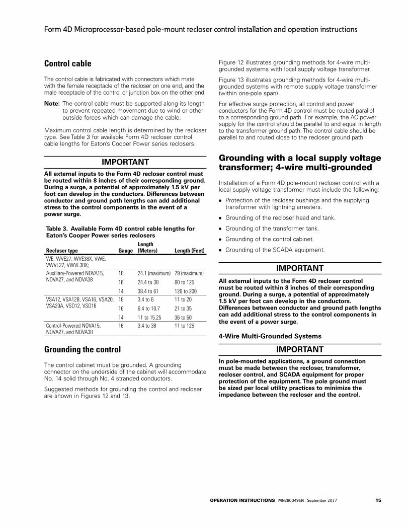
Control cable
The control cable is fabricated with connectors which mate with the female receptacle of the recloser on one end, and the male receptacle of the control or junction box on the other end.
otee:N The control cable must be supported along its length to prevent repeated movement due to wind or other outside forces which can damage the cable.
Maximum control cable length is determined by the recloser type. See Table 3 for available Form 4D recloser control cable lengths for Eaton’s Cooper Power series reclosers.
IMPORTANTAll external inputs to the Form 4D recloser control must be routed within 8 inches of their corresponding ground. During a surge, a potential of approximately 1.5 kv per foot can develop in the conductors. Differences between conductor and ground path lengths can add additional stress to the control components in the event of a power surge.
Table 3. Available Form 4D control cable lengths for Eaton’s Cooper Power series reclosers
Recloser type GaugeLength (Meters) Length (Feet)
WE, WVE27, WVE38X, VWE, VWVE27, VWVE38X;Auxiliary-Powered NOVA15, NOVA27, and NOVA38
18
16
14
24.1 (maximum)
24.4 to 38
38.4 to 61
79 (maximum)
80 to 125
126 to 200VSA12, VSA12B, VSA16, VSA20, VSA20A, VSO12, VSO16
18
16
14
3.4 to 6
6.4 to 10.7
11 to 15.25
11 to 20
21 to 35
36 to 50Control-Powered NOVA15, NOVA27, and NOVA38
16 3.4 to 38 11 to 125
Grounding the control
The control cabinet must be grounded. A grounding connector on the underside of the cabinet will accommodate No. 14 solid through No. 4 stranded conductors.
Suggested methods for grounding the control and recloser are shown in Figures 12 and 13.
Figure 12 illustrates grounding methods for 4-wire multi-grounded systems with local supply voltage transformer.
Figure 13 illustrates grounding methods for 4-wire multi-grounded systems with remote supply voltage transformer (within one-pole span).
For effective surge protection, all control and power conductors for the Form 4D control must be routed parallel to a corresponding ground path. For example, the AC power supply for the control should be parallel to and equal in length to the transformer ground path. The control cable should be parallel to and routed close to the recloser ground path.
Grounding with a local supply voltage transformer; 4-wire multi-grounded
Installation of a Form 4D pole-mount recloser control with a local supply voltage transformer must include the following:
Protection of the recloser bushings and the supplying transformer with lightning arresters.
Grounding of the recloser head and tank.
Grounding of the transformer tank.
Grounding of the control cabinet.
Grounding of the SCADA equipment.
IMPORTANT
All external inputs to the Form 4D recloser control must be routed within 8 inches of their corresponding ground. During a surge, a potential of approximately 1.5 kv per foot can develop in the conductors. Differences between conductor and ground path lengths can add additional stress to the control components in the event of a power surge.
4-Wire Multi-grounded Systems
IMPORTANT In pole-mounted applications, a ground connection must be made between the recloser, transformer, recloser control, and SCADA equipment for proper protection of the equipment. The pole ground must be sized per local utility practices to minimize the impedance between the recloser and the control.
15operation inStrUCtionS MN280049EN September 2017
Form 4D Microprocessor-based pole-mount recloser control installation and operation instructions

SurgeArrester
RecloserHead Ground
SurgeArresterTransformer
SurgeArrester
Arrester Ground
Recloser
Pole
SupplyVoltage
PoleGround
Form 4DControl
Customer Ground ConnectionAt External Lug
NE
UA
C
GNDNEUAC
InputTerminalBlock
ControlCable
AC
NEUTRAL
Form 4D ControlSupply Voltage
Transformer
ELECTRICAL CONNECTIONS Line to Neutral connected transformer
Input TerminalBlock TB1
External Ground Lug
Figure 12. Recommended grounding method for the Form 4D pole-mount recloser control installed on 4-wire multi-grounded, with local supply voltage transformer
WARNINgHazardous voltage. Recloser and control must be solidly grounded. Follow all locally approved procedures and safety practices when grounding this equipment. Improper grounding can result in contact with high voltage, which will cause death or severe personal injury. g115.1
Grounding with a remote supply voltage transformer; 4-wire multi-groundedInstallation of a Form 4D pole-mount recloser control with a remote supply voltage transformer must include the following:
Protection of the recloser bushings and the supplying transformer with lightning arresters.
Grounding of the recloser head and tank.
Grounding of the transformer tank.
Grounding of the control cabinet.
Grounding of the SCADA equipment.
IMPORTANTIn pole-mounted applications, a ground connection must be made between the recloser, transformer, recloser control, and SCADA equipment for proper protection of the equipment. The pole ground must be sized per local utility practices to minimize the impedance between the recloser and the control.
IMPORTANTAll external inputs to the Form 4D recloser control must be routed within 8 inches of their corresponding ground. During a surge, a potential of approximately 1.5 kv per foot can develop in the conductors. Differences between conductor and ground path lengths can add additional stress to the control components in the event of a power surge.
IMPORTANTDistance between transformer and recloser should be one pole span or less.
16 operation inStrUCtionS MN280049EN September 2017
Form 4D Microprocessor-based pole-mount recloser control installation and operation instructions

SurgeArrester
RecloserHeadGround
SupplyVoltage
PoleGround
Pole
Recloser
Pole
SurgeArrester
Transformer
ArresterGround
Form 4D Control
HOTNEUGND
NEU
AC
Input Terminal Block
Control Cable
SurgeArrester
ArresterGround
Customer Ground Connectionat External Lug
AC
NEUTRAL
Form 4D ControlSupply Voltage
Transformer
ELECTRICAL CONNECTIONS - Remote dedicated supply transformer
InputTerminalBlock TB1
ExternalGround Lug
Note: Distance between transformer and recloser should be one pole span or less.
System
Neutral
Figure 13. Recommended grounding method for the Form 4D recloser control installed on 4-wire multi-grounded with remote supply voltage transformer
WARNINgHazardous voltage. Recloser and control must be solidly grounded. Follow all locally approved procedures and safety practices when grounding this equipment. Improper grounding can result in contact with high voltage, which will cause death or severe personal injury.
Customer connections for AC power
CAuTIONEquipment damage. Do not drill connection holes into the top of the cabinet. Connection holes in the top of the cabinet will allow moisture to seep into the control and damage the components or cause control misoperation. Failure to comply will void the control’s factory warranty.
17operation inStrUCtionS MN280049EN September 2017
Form 4D Microprocessor-based pole-mount recloser control installation and operation instructions

Input power to the Form 4D pole-mount recloser control is connected to terminal block TB1 or AC input receptacle if provided.
DANgERHazardous voltage. Do not connect potential transformer low-voltage secondaries to the control through cables or other wiring until the unit is installed in the field. Transformer high-voltage primary windings will become live when 120/240v AC is applied to the control from an alternate source if the transformer secondary is connected. Failure to comply may result in severe personal injury or death. T371.2
WARNINgHazardous voltage. Before applying power to the control, confirm that male pins of the input power receptacle are electrically insulated to prevent unintentional contact with 120/240v AC voltage. Failure to do so may result in severe personal injury or death. T372.1
IMPORTANTuse a touch-safe DIN rail terminal block tool when working near terminal blocks. This tool is included with the control.
See Figures 14, 15, and 16 for single-phase incoming voltage supply for 120 VAC or 240 VAC.
Refer to Accessory section for 120 VAC or 240 VAC low voltage closing.
Input power is required:
To power the control. To provide voltage and power metering. To power the thermostatically controlled heater. For the low voltage closing accessory (optional). For the convenience outlet accessory (optional). Charge the battery(s).
Battery chargerThe battery charger is enabled whenever the Form 4D control is connected to incoming line power.
An 8 A-hr lead acid battery will fully charge in 24 hours or less, at 25°C.
A 13 A-hr lead acid battery will fully charge in 39 hours or less, at 25°C.
The charger includes a temperature-compensated design to optimally charge the control battery.
Terminal blocksOne terminal block is used for connection to the Form 4D recloser control. Input power and sensing voltage terminal blocks will allow a maximum wire size of #12 AWG.
Terminal Block TB1 provides power and sensing voltage to the Form 4D recloser control modules. Terminal Block TB1 is used to connect sensing transformer voltage. The wiring of the transformers should follow the application illustrations per Figures 14, 15, and 16.
The factory-default wiring from TB1-L1 to TB1-V2+ connects the metering B phase to the control power supply voltage.
If the incoming power supply voltage is not B phase, move the phase jumper on TB1 as follows:
For A-phase metering, connect TB1-L1 to TB1-V1+.
For C-phase metering, connect TB1-L1 to TB1-V3+.
otee:N Terminal Block positions TB1-N and TB1-N are factory-jumpered together.
otee:N Terminal Block positions TB1-L1 and TB1-L1 are factory-jumpered together.
Power connectionsThe transformer required for power should be a minimum of 5 kVA for low-voltage AC closing reclosers and 1 kVA for high voltage AC closing reclosers and NOVA reclosers.
External voltage sensingVoltage Sensing inputs are provided for customer connections to load-side and source-side PTs.
Input voltage range:
0 – 40 VAC (low range).
0 – 305 VAC (high range).
The input range is automatically selected based on V expected and PT ratio settings:
Low range is selected if V expected/PT Ratio is <= 20.
High range is selected if V expected/PT Ratio > 20.
To avoid erroneous metering values:
Do not exceed the input voltage range.
Set “PT Connection Type” in the ProView NXG software System Configuration dialog to “None” if external voltage sensing is not used. This will blank out the voltage sense readings.
Set the PT ratio to 1 for all unconnected voltage sense inputs.
Follow the grounding requirements shown on the Voltage Sensing wire diagram appropriate for your Wye or Delta application (Figures 17 or 18).
18 operation inStrUCtionS MN280049EN September 2017
Form 4D Microprocessor-based pole-mount recloser control installation and operation instructions

otee:N The Form 4D control only displays Line-to-Neutral voltages regardless of the system connection.
Refer to Service Information S280-104-2 Form 4D Microprocessor-Based Recloser Control Programming Guide for additional information.
Figure 14. 120 or 240 vAC 2-wire control power input (shown with default factory wiring connected to B-phase voltage metering with B-phase incoming supply)
19operation inStrUCtionS MN280049EN September 2017
Form 4D Microprocessor-based pole-mount recloser control installation and operation instructions

Figure 15. 120 or 240 vAC 2-wire with ground control power input (shown with default factory wiring connected to B-phase voltage metering with B-phase incoming supply)
20 operation inStrUCtionS MN280049EN September 2017
Form 4D Microprocessor-based pole-mount recloser control installation and operation instructions

Figure 16. 120/240 vAC 3-wire center-tapped PT control power input (shown with default factory wiring connected to B-phase voltage metering with B-phase incoming supply)
21operation inStrUCtionS MN280049EN September 2017
Form 4D Microprocessor-based pole-mount recloser control installation and operation instructions
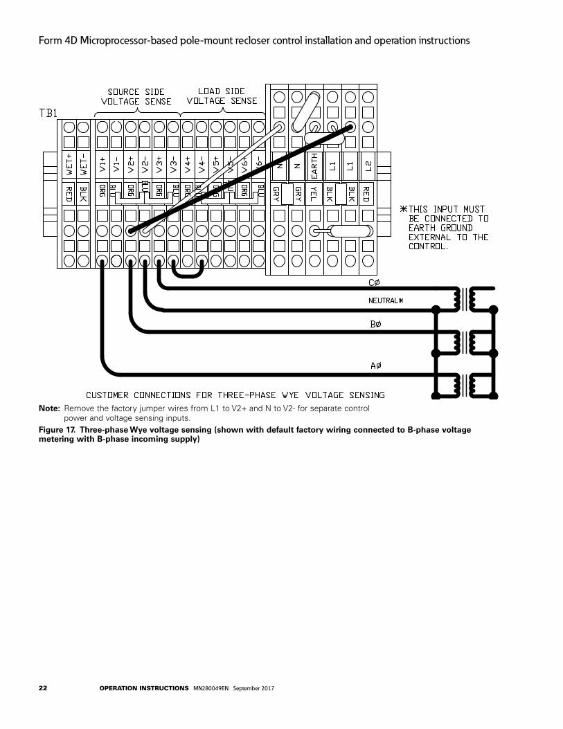
Figure 17. Three-phase Wye voltage sensing (shown with default factory wiring connected to B-phase voltage metering with B-phase incoming supply)
otee:N Remove the factory jumper wires from L1 to V2+ and N to V2- for separate control power and voltage sensing inputs.
22 operation inStrUCtionS MN280049EN September 2017
Form 4D Microprocessor-based pole-mount recloser control installation and operation instructions

Figure 18. Three-phase Delta voltage sensing (shown with default factory wiring connected to B-phase voltage metering with B-phase incoming supply). The Form 4D control only displays Line-to-Neutral voltages regardless of the system connection
ote
e:N
The
Form
4D
con
trol
onl
y di
spla
ys L
ine-
to-N
eutr
al v
olta
ges
rega
rdle
ss o
f th
e sy
stem
con
nect
ion.
ote
e:N
Rem
ove
the
fact
ory
jum
per
wire
s fr
om L
1 to
V2+
and
N t
o V
3+ f
or s
epar
ate
cont
rol p
ower
and
vol
tage
sen
sing
inpu
ts.
23operation inStrUCtionS MN280049EN September 2017
Form 4D Microprocessor-based pole-mount recloser control installation and operation instructions

Customer connections for contact i/o module option
CAuTIONEquipment damage. Do not drill connection holes into the top of the cabinet. Connection holes in the top of the cabinet will allow moisture to seep into the control and damage the components or cause control misoperation. Failure to comply will void the control’s factory warranty. T249.0
The Contact I/O module (Figure 19) permits connection of contact-type input devices (switches, relays) and indicating devices (relays, LEDs, lamps) to the Form 4D control to effect local Contact input/output (I/O). The Contact I/O module accessory is used for supplementing normal local controls and status indicators for Contact I/O functions. The first optional Contact I/O module inputs and outputs are factory-set and are shown in Figure 20.
Additional I/O modules require customer configuration to assign functionality for each contact input or output — via the ProView NXG software configurable logic tool. Refer to Service Information S280-104-2 Form 4D Microprocessor-Based Recloser Control Programming Guide for additional information.
IMPORTANT The control gives priority to TCC timing and issuing a trip signal rather than changing the status of a Contact I/O module output or responding to a Contact I/O module input. Refer to Table 4 for I/O response times.
The Contact I/O module for the first I/O card contains four factory-set inputs and four outputs for Contact I/O functions. Each Form 4D control can accommodate up to four Contact I/O modules.
Whetting voltage is supplied from TB1 for the Contact I/O inputs terminal block on the back panel as shown in Figure 20.
Two of the Contact I/O outputs are Form A relay contacts and two are Form C relay contacts. All four outputs are of non-latching type. Refer to Table 5 Output Ratings for output fusing recommendations.
otee:N Latching is defined as an output that retains its status when control power is removed.
Non-latching is defined as an output that returns to a default status when control power is removed.
otee:N Following a firmware upgrade the Contact I/O module output relays will revert to the de-energized state. Additionally, the Contact I/O module may need to be remapped.
NOTICEExternal leads must be shielded and the shield must be grounded at both ends. Terminate each lead with a 320 vAC, 150 Joules metal oxide resistor (MOv), or equivalent, at the remote end. Attach MOvs between the leads and ground. Failure to properly shield and protect leads can result in equipment damage and/or unintentional operation.
Figure 19. Contact I/O Module
24 operation inStrUCtionS MN280049EN September 2017
Form 4D Microprocessor-based pole-mount recloser control installation and operation instructions
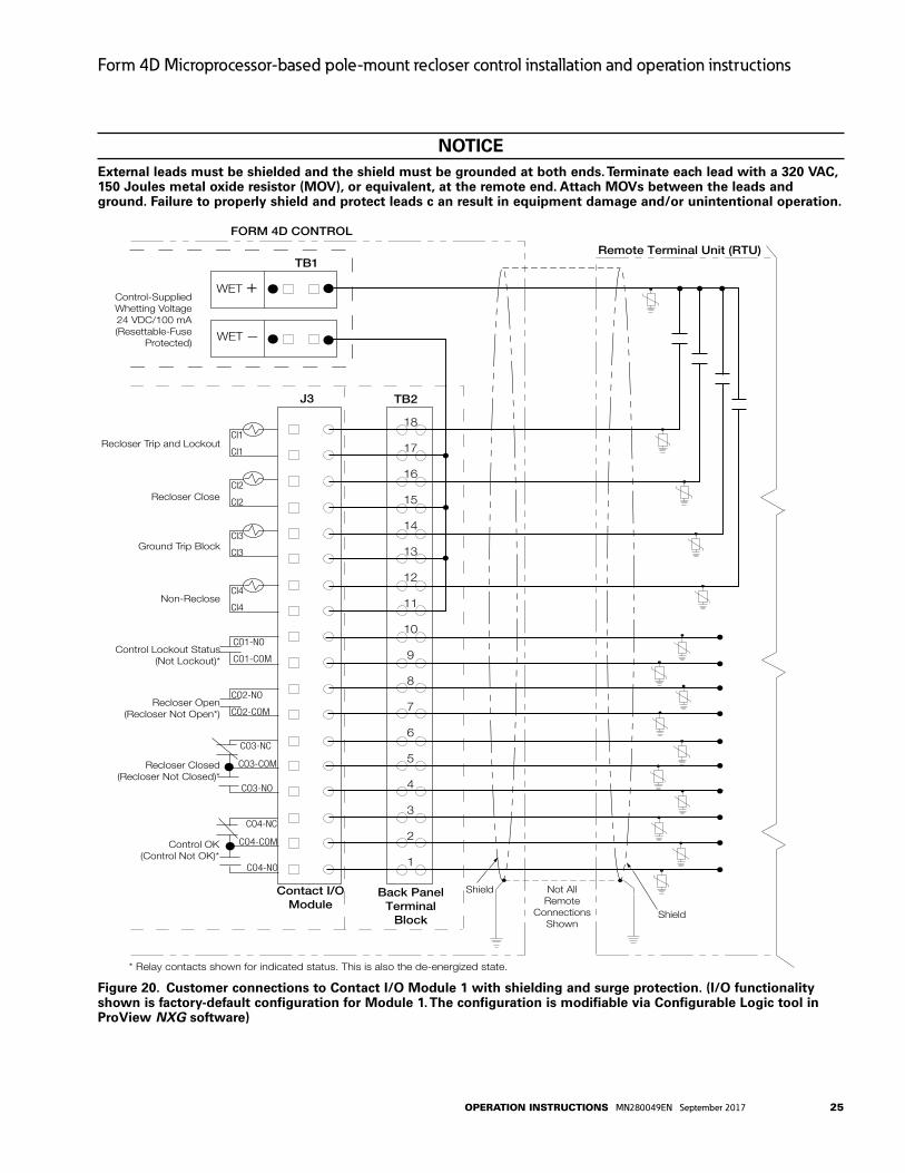
NOTICEExternal leads must be shielded and the shield must be grounded at both ends. Terminate each lead with a 320 vAC, 150 Joules metal oxide resistor (MOv), or equivalent, at the remote end. Attach MOvs between the leads and ground. Failure to properly shield and protect leads c an result in equipment damage and/or unintentional operation.
FORM 4D CONTROL
Remote Terminal Unit (RTU)
Not AllRemote
ConnectionsShown
Contact I/OModule
J3
Recloser Trip and Lockout
Recloser Close
Ground Trip Block
Non-Reclose
Control Lockout Status(Not Lockout)*
Recloser Open(Recloser Not Open*)
Recloser Closed(Recloser Not Closed)*
Control OK(Control Not OK)*
18
17
16
15
14
13
12
11
10
9
8
7
6
5
4
3
2
1
TB1
WET +
WET —
Control-SuppliedWhetting Voltage24 VDC/100 mA(Resettable-Fuse
Protected)
Shield
Shield
Back PanelTerminal
Block
TB2
CO4-NO
CI1
CI1
CI2
CI2
CI3
CI3
CI4
CI4
CO1-NO
CO1-COM
CO2-NO
CO2-COM
CO3-NO
CO3-NC
CO3-COM
CO4-NC
CO4-COM
* Relay contacts shown for indicated status. This is also the de-energized state.
Figure 20. Customer connections to Contact I/O Module 1 with shielding and surge protection. (I/O functionality shown is factory-default configuration for Module 1. The configuration is modifiable via Configurable Logic tool in Proview NXG software)
25operation inStrUCtionS MN280049EN September 2017
Form 4D Microprocessor-based pole-mount recloser control installation and operation instructions

Table 4. Contact I/O option module input ratings
Minimum Detection Level: 10 V (AC rms or DC) (50 or 60Hz) (Using control-supplied whetting Voltage is recommended)
Maximum Applied Voltage: 250 VAC, rms, or 125 VDCNominal Input Loading: 2 mA per input (internally current limited)Typical Control Response Time: 50 msec (Note: Protection tasks take priority over input activity.)Minimum Input Pulse Time: 250 msecMinimum Transition Time between Pulse Inputs: 250 msecInput Protection: Shunting type using MOVs and capacitors.
Optical Isolation from input to system. (1500 VAC, rms)Hi-Pot Capability: 3.150 kV DC for 1 second, from one input set to the next or from one pin to chassis, but not
across the two terminals of a single input (due to MOVs).
Table 5. Output ratings
Maximum Switching Voltage: 250 VAC, rms or 125 VDCMaximum Switching Loading: Refer to Figure 21.Maximum Pickup Time: 8 msec (not including control response time)Maximum Release Time: 15 msec (not including control response time)Output Protection: Shunting type using MOVs and capacitors. 1500 VAC, rms isolation between coil and contactsHi-Pot Capability: 3.150 kV DC for 1 second from one output to the next or from one pin to chassis, but not across two terminals of a
single output (due to output protection).Fusing: Outputs are not internally fuse-protected. Customer-supplied fusing is recommended.
AC
Res
istiv
e Lo
ad:
DC
Res
istiv
e Lo
ad:
Leg
end
Figure 21. Maximum output switching graph
Before placing the control and the recloser into service
CAuTIONEquipment misoperation. Do not connect this control to an energized recloser until all control settings have been properly programmed and verified. Refer to the programming information for this control. Failure to comply can result in control and recloser misoperation, equipment damage, and personal injury.
IMPORTANTTo avoid damage to the wiring or batteries, do not transport the control with the batteries installed.
otee:N When opened, both the cabinet door and the inside swing panel door lock into the open position. Lift the door or swing panel up to raise the hinge out of the locking position prior to closing the inside swing panel door or the cabinet door.
26 operation inStrUCtionS MN280049EN September 2017
Form 4D Microprocessor-based pole-mount recloser control installation and operation instructions

Prior to placing the control and recloser into service, the following installation procedures must be properly completed and verified:
1. Front panel label inserts changed (if applicable).
otee:N Refer to using Removable Inserts section in this manual for additional information.
2. Control properly mounted for the installation.
3. Recloser installed according to all locally approved standards and practices.
4. AC disconnect switches installed.
5. Control and recloser properly grounded in accordance with guidelines in this manual and the applicable recloser manual.
6. Control cable properly connected and supported.
7. Control battery connected and tested for proper operation.
otee:N The battery test runs within 60 seconds upon power-up of the control.
otee:N The battery cannot be tested when the control is powered from the battery only (no AC power). If a battery test is attempted with battery power only, the test results will display as ATTENTION – 4 (Battery Test Blocked).
View battery information and test battery operation as follows:
a. Scroll down the front panel HMI to the BATTERY menu item and press the ENTER button. Code 081 Battery Voltage and Current will be displayed:
VBat = XX.XX Volts
IBat = -X.XX Amps
b. Press the down arrow button to scroll to the Test Battery command. Press the ENTER button.
The following message will appear: 082 Test Battery (CONFIRM).
c. Press the ENTER key. The (TESTING...) message will appear. (The test duration is approximately five seconds.)
If the battery is OK, the (PASS) message will appear.
If the battery is not OK, one of these messages will appear:
“ATTENTION – 1” indicates Battery Test Trouble*“ATTENTION – 2” indicates Battery Test Failed
“ATTENTION – 3” indicates Battery TestCurrently Running
“ATTENTION – 4” indicates Battery TestBlocked**
d. The battery test results can be viewed by pressing the down arrow. The following information will be displayed:
VBat = XX.XX Volts
IBat = -X.XX Amps
8. AC power connected to the control.
otee:N The control includes a Power Save feature that will turn off the LEDs and backlit LCD display after 15 minutes of inactivity at the front panel (no buttons pressed). The CONTROL OK and HOT LINE TAG LEDs are not affected by the power save mode. Pressing any key on the front panel will turn the LCD backlight on and restore all LEDs to their current on/off states.
9. All control programming entered and verified by appropriate personnel.
otee:N Refer to Service Information S280-104-2 Form 4D Microprocessor-Based Recloser Control Programming Guide for additional information.
10. Control clock set to the correct time.
otee:N Refer to Service Information S280-104-2 Form 4D Microprocessor-Based Recloser Control Programming Guide Clock Menu for additional information.
NOTICEExternal leads must be shielded and the shield must be grounded at both ends. Terminate each lead with a 320 vAC, 150 Joules metal oxide resistor (MOv), or equivalent, at the remote end. Attach MOvs between the leads and ground. Failure to properly shield and protect leads can result in equipment damage and/or unintentional operation.
11. Customer connections for remote and supervisory operation checked and completed in accordance with proper shielding and surge protection (Figure 20).
* Battery Test Trouble indicates that the test results were not lower than battery failure voltage (15V) and not higher than the test voltage (22.8V).
** Battery Test Blocked indicates a battery test was attempted with battery power only. The battery cannot be tested when the control is powered from the battery only (no AC power).
27operation inStrUCtionS MN280049EN September 2017
Form 4D Microprocessor-based pole-mount recloser control installation and operation instructions
Accessories
These accessories are available. Contact your Eaton representative for additional information.
Low voltage closingThe Low Voltage Closing Accessory utilizes 120 or 240 VAC for closing power (Figures 22, 23, and 24). Multiple low voltage closing accessories are available for reclosers equipped with low voltage closing. The low voltage closing accessories available for the Form 4D recloser control include the appropriate receptacles and wiring based upon the input supply voltage. Table 6 lists the available low voltage closing input/output receptacles and cables for the Form 4D pole-mount recloser control.
Cabinet ordering accessories AISI 304 stainless steel cabinet construction.
Incoming power receptaclesThe Incoming Power Receptacle allows the user to conveniently plug the power cable into the control, eliminating the need for hardwiring to the control. Various options are available based upon the input power voltage, and phase sensing requirements. Table 6 includes the available input receptacles and cables for the Form 4D pole-mount recloser control.
Internal voltage sensingA four-wire cable and input receptacle accessory (Table 7) is required for Type NOVA three-phase reclosers with the internal voltage sensing (IVS) option. Internal voltage sensors, located on the source side, indicate voltage magnitude within an accuracy 2% or better and a phase degree accuracy within 1.5 degrees (includes sensor, cable, and control). The 4-pin receptacle accessory is pre-wired to the voltage inputs on the control. Refer to Service Instructions S280-42-1 NOVA Three-Phase Recloser Installation and Operation Instructions for additional setting information.
Table 6. Receptacles and wiring; input and low voltage closing cables*
Description Catalog number120 VAC low-voltage closing 2-pin input and 2-pin output receptacles KME4D-1775-A120 VAC low-voltage closing with 3-pin input and 2-pin output receptacles KME4D-1775-B120 VAC low-voltage closing with inlet hole and 2-pin output receptacle KME4D-1775-C240 VAC low-voltage closing with 2-pin input and 2-pin output receptacle KME4D-1775-D240 VAC low-voltage closing with 3-pin input and 2-pin output receptacle KME4D-1775-E240 VAC low voltage closing, for 2-wire with inlet hole and 2-pin output receptacle KME4D-1775-F240 VAC low-voltage closing, for 3-wire with inlet hole and 2-pin output receptacle KME4D-1775-G120 VAC or 240 VAC input receptacle, 2-pin KME4D-1775-H120 VAC input receptacle, 3-pin KME4D-1775-J 240 VAC input receptacle, 3-pin KME4D-1775-KAC Input Cable, 120 or 240 VAC, 2-wire for 2-pin input for use with KME4D-1775-A, KME4D-1775-D, or KME4D-1775-H receptacles. Replace X with desired length. Select from 10 to 80 feet.
KA11ME1-X
AC Input Cable, 240 VAC, 3-wire for 3-pin input for use with KME4D-1775-E or KME4D-1775-K receptacles. Replace X with desired length. Select from 10 to 80 feet.
KME4-67-2-X
AC Input Cable, 120 VAC, 3-wire for 3-pin input for use with KME4D-1775-B and KME4D-1775-J receptacles. Replace X with desired length. Select from 10 to 80 feet.
KME4-67-3-X
Low Voltage Closing Cable, 2-wire for use with KME4D-1775-A, KME4D-1775-B, KME4D-1775-C, KME4D-1775-D, KME4D-1775-E, KME4D-1775-F, and KME4D-1775-G low voltage closing receptacles. Replace X with desired length. Select from 10 to 80 feet.
KA13ME1-X
*Low-voltage closing receptacles are only applicable to Eaton’s Cooper Power series auxiliary and line-powered reclosers with 14-pin connection (WE,WVE27, WVE38X, VWE, VWVE27, VWVE38X, VSA12, VSA12B, VSA16, VSA20, VSA20A, VSO12, VSO16, NOVA15, NOVA27, NOVA38).
Table 7. Internal voltage sensingDescription Catalog numberInternal voltage sensing input receptacle, 4-pin KME4D-3799-A
otee:N Internal voltage sensing receptacle is only compatible with reclosers equipped with internal voltage sensors.
otee:N The internal voltage sensing cable (KA97ME) is ordered with the recloser. If a replacement cable is required, contact your Eaton representative.
28 operation inStrUCtionS MN280049EN September 2017
Form 4D Microprocessor-based pole-mount recloser control installation and operation instructions

DANgERHazardous voltage. Do not connect potential transformer low-voltage secondaries to the control through cables or other wiring until the unit is installed in the field. Transformer high-voltage primary windings will become live when 120/240v AC is applied to the control from an alternate source if the transformer secondary is connected. Failure to comply may result in severe personal injury or death. T371.2
WARNINgHazardous voltage. Before applying power to the control, confirm that male pins of the input power receptacle are electrically insulated to prevent unintentional contact with 120/240v AC voltage. Failure to do so may result in severe personal injury or death.
Figure 22. 120 or 240 vAC 2-wire control power input with low voltage closing (shown with default factory wiring connected to B-phase voltage metering with B-phase incoming supply)
29operation inStrUCtionS MN280049EN September 2017
Form 4D Microprocessor-based pole-mount recloser control installation and operation instructions
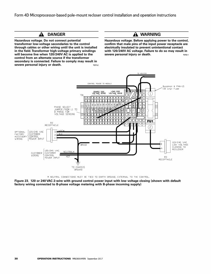
DANgERHazardous voltage. Do not connect potential transformer low-voltage secondaries to the control through cables or other wiring until the unit is installed in the field. Transformer high-voltage primary windings will become live when 120/240v AC is applied to the control from an alternate source if the transformer secondary is connected. Failure to comply may result in severe personal injury or death. T371.2
WARNINgHazardous voltage. Before applying power to the control, confirm that male pins of the input power receptacle are electrically insulated to prevent unintentional contact with 120/240v AC voltage. Failure to do so may result in severe personal injury or death. T372.1
Figure 23. 120 or 240 vAC 2-wire with ground control power input with low voltage closing (shown with default factory wiring connected to B-phase voltage metering with B-phase incoming supply)
30 operation inStrUCtionS MN280049EN September 2017
Form 4D Microprocessor-based pole-mount recloser control installation and operation instructions

WARNINgHazardous voltage. Before applying power to the control, confirm that male pins of the input power receptacle are electrically insulated to prevent unintentional contact with 120/240v AC voltage. Failure to do so may result in severe personal injury or death. T372.1
DANgERHazardous voltage. Do not connect potential transformer low-voltage secondaries to the control through cables or other wiring until the unit is installed in the field. Transformer high-voltage primary windings will become live when 120/240v AC is applied to the control from an alternate source if the transformer secondary is connected. Failure to comply may result in severe personal injury or death. T371.2
Figure 24. 120/240 vAC 3-wire center-tapped PT control power input with 240 vAC low voltage closing (shown with default factory wiring connected to B-phase voltage metering with B-phase incoming supply)
31operation inStrUCtionS MN280049EN September 2017
Form 4D Microprocessor-based pole-mount recloser control installation and operation instructions

Cable locking sleevesTo prevent detachment of the control cable from the control cabinet by unauthorized personnel, a cable-locking sleeve (Catalog Number KME4D-1772-X [replace X with quantity: maximum 5]) is available to enclose the cable plug. The plug is passed through the sleeve and the sleeve is then fastened from inside the control cabinet. There is no access to the cable receptacle without opening the locked cabinet door and detaching the sleeve.
BCT Terminal blocks accessories Separate BCT terminal blocks provide a connection point for external 600:5 or 1200:5 multi-ratio bushing current transformers. BCT terminal blocks are available for both the load or source sides and include wire for all ratios of the BCT. Refer to Table 8 and Figure 25.
Auxiliary ter minal block accessoryAn auxiliary terminal block and receptacle is available for three-stage auxiliary switch wiring. Refer to Table 8 and Figure 25.
Table 8. Terminal blocks (maximum 12-gauge wire)Description Catalog numberBCT shorting-type terminal block for (LOAD) bushings 2, 4, 6
KME4D-1773-A
BCT shorting-type terminal block for (SOURCE) bushings 1, 3, 5
KME4D-1773-B
Terminal block and receptacle for wiring of three-stage auxiliary switch, KA542R3
KME4D-1801-11
otee:N For every one terminal block accessory ordered, the maximum additional I/O allowed quantity is reduced by one.
Auxiliary Terminal Block Accessory
BCT Terminal
Blocks
Figure 25. Sample BCT terminal blocks configuration and positioning of auxiliary terminal block accessory
Table 9. Miscellaneous accessories
Description Catalog number
120 VAC battery charger for spare batteries KME5-60-1
Made in USA decal K89-407-1
120 VAC GFI Duplex outletThe GFI Duplex Outlet (Catalog Number KME4D-1776) is available for controls powered by 120 VAC or 240 VAC three-wire supply power. This convenience outlet is rated for 3 Amperes and is accessible through the front door in the control cabinet. The 120 VAC GFI Duplex Outlet is used for many applications such as power for the MET Tester, auxiliary measurement equipment, and supplemental lighting.
Automation accessory packagesThe Form 4D control includes an auxiliary power supply that provides a customer connection to 13.5VDC. This source is intended to be used to power radios and other communications support equipment for connection to SCADA and other remote communications systems. The power supply is backed up by the control batteries in the Form 4D control cabinet, and will continue to provide power to connected accessories under loss of AC line power to the recloser control. A maximum of 12W continuous and 30W peak (intermittent) power can be delivered to accessories connected to the auxiliary power supply.
A variety of automation packages are available to be used in conjunction with the auxiliary power supply to facilitate the mounting and proper connection of antennas to radios mounted in the control cabinet. Packages are available to support many popular radio technologies and frequency bands. See Table 10 for details on each of the available automation accessory packages.
Table 10. Automation accessory packages (A maximum of two accessories can be ordered. KME4D-1774-21 is not included in this maximum.) Description Catalog numberWireless communication provisions package 13.5 VDC interface board, radio mounting tray (Radio and communications interface cards not included)
KME4D-1774-21
Cellular communications connection and protection package 32” SMA(m)-N(m) coax pigtail, 700MHz - 2GHz PolyPhaser and mounting hardware, N(f)-type external termination
KME4D-1774-14*
WiFi/WiMax communications connection and protection package 32” SMA(m)-N(m) coax pigtail, 2GHz-6GHz Polyphaser and
mounting hardware, N(f)-type external termination, TNC(m)-SMA(m) inline coaxial adapter
KME4D-1774-15*
125MHz to 1GHz N-terminated radio connection and protection package 25” N(m)-N(m) coax pigtail, 125MHz to 1GHz PolyPhaser and mounting hardware, N(f)-type external termination
KME4D-1774-16*
700MHz to 2GHz TNC-terminated radio connection and protection package 32” TNC(m)-N(m) coax pigtail, 700MHz to 2GHz
PolyPhaser and mounting hardware, N(f)-type external termination
KME4D-1774-17*
PolyPhaser and mounting hardware - 125MHz-1GHz KME4D-1774-A*PolyPhaser and mounting hardware - 700MHz-2GHz KME4D-1774-B*PolyPhaser and mounting hardware - 2GHz-6GHz KME4D-1774-C** Requires that the KME4D-1774-21 wireless communication provisions
package also be ordered.
32 operation inStrUCtionS MN280049EN September 2017
Form 4D Microprocessor-based pole-mount recloser control installation and operation instructions

otee:N Corresponding communication interfaces from Port 1 and/or Port 2 must be ordered in conjunction with automation accessories.
Communication board accessoriesThe Form 4D pole-mount control is equipped with two communication board accessory expansion bays offering versatile support for modern communication media (Figure 26). Five distinct communication options (Figure 27) are available, providing two-way, real time digital communications with a remote terminal unit (RTU), wireless, telephone modem, Ethernet network, or other communication devices. Any combination of two communication boards can be installed. The following options are available:
RS-232 (isolated) Serial communication card.
RS-485 (isolated) Serial communication card.
Fiber-optic-based Serial communication card with ST Connectors.
10/100 Base-T/TX Ethernet communication card with RJ-45 connector.
100 Base-FX Ethernet communication card with four connector options supporting both single- and multi-mode.
Additional accessories are being continuously developed. Contact your Eaton representative for the latest information regarding particular media and communication protocol support.
Figure 26. Form 4D pole-mount recloser control side panel communication ports
Ethernet copper, RJ-45Ethernet fiber, ST
Ethernet fiber, MTRJ Serial, RS-232
Ethernet fiber, LC Serial, RS-485
Ethernet fiber, SC Serial fiber, STFigure 27. Side panel communication options
33operation inStrUCtionS MN280049EN September 2017
Form 4D Microprocessor-based pole-mount recloser control installation and operation instructions
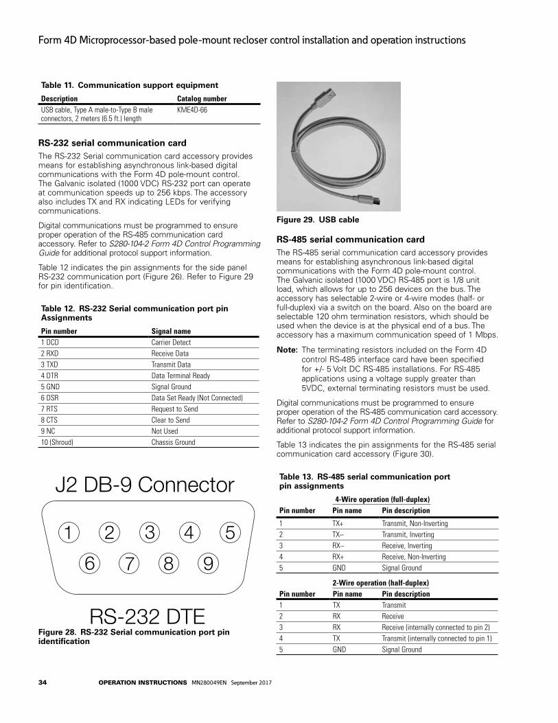
Table 11. Communication support equipment
Description Catalog numberUSB cable, Type A male-to-Type B male connectors, 2 meters (6.5 ft.) length
KME4D-66
RS-232 serial communication cardThe RS-232 Serial communication card accessory provides means for establishing asynchronous link-based digital communications with the Form 4D pole-mount control. The Galvanic isolated (1000 VDC) RS-232 port can operate at communication speeds up to 256 kbps. The accessory also includes TX and RX indicating LEDs for verifying communications.
Digital communications must be programmed to ensure proper operation of the RS-485 communication card accessory. Refer to S280-104-2 Form 4D Control Programming Guide for additional protocol support information.
Table 12 indicates the pin assignments for the side panel RS-232 communication port (Figure 26). Refer to Figure 29 for pin identification.
Table 12. RS-232 Serial communication port pin Assignments
Pin number Signal name1 DCD Carrier Detect2 RXD Receive Data3 TXD Transmit Data4 DTR Data Terminal Ready5 GND Signal Ground6 DSR Data Set Ready (Not Connected)7 RTS Request to Send8 CTS Clear to Send9 NC Not Used10 (Shroud) Chassis Ground
RS-232 DTE
J2 DB-9 Connector
1 2 3 4 5
6 7 8 9
Figure 28. RS-232 Serial communication port pin identification
Figure 29. uSB cable
RS-485 serial communication cardThe RS-485 serial communication card accessory provides means for establishing asynchronous link-based digital communications with the Form 4D pole-mount control. The Galvanic isolated (1000 VDC) RS-485 port is 1/8 unit load, which allows for up to 256 devices on the bus. The accessory has selectable 2-wire or 4-wire modes (half- or full-duplex) via a switch on the board. Also on the board are selectable 120 ohm termination resistors, which should be used when the device is at the physical end of a bus. The accessory has a maximum communication speed of 1 Mbps.
otee:N The terminating resistors included on the Form 4D control RS-485 interface card have been specified for +/- 5 Volt DC RS-485 installations. For RS-485 applications using a voltage supply greater than 5VDC, external terminating resistors must be used.
Digital communications must be programmed to ensure proper operation of the RS-485 communication card accessory. Refer to S280-104-2 Form 4D Control Programming Guide for additional protocol support information.
Table 13 indicates the pin assignments for the RS-485 serial communication card accessory (Figure 30).
Table 13. RS-485 serial communication port pin assignments
4-Wire operation (full-duplex)Pin number Pin name Pin description
1 TX+ Transmit, Non-Inverting2 TX– Transmit, Inverting3 RX– Receive, Inverting4 RX+ Receive, Non-Inverting5 GND Signal Ground
2-Wire operation (half-duplex)Pin number Pin name Pin description1 TX Transmit2 RX Receive3 RX Receive (internally connected to pin 2)4 TX Transmit (internally connected to pin 1)5 GND Signal Ground
34 operation inStrUCtionS MN280049EN September 2017
Form 4D Microprocessor-based pole-mount recloser control installation and operation instructions

Figure 30. Lefte: Location of TERMINATINg RESISTORS ON/OFF and HALF/FuLL DuPLEX switch on the RS-485 board Righte: RS-485 serial communication port pin identification.
Figure 31. ECHO ON/OFF switch location on the serial-fiber board
Fiber-optic based serial communication cardThe Fiber-Optic based serial communication card (Figure 31) offers means of establishing asynchronous (RS-232 like) digital communications through multi-mode fiber media. The use of the fiber-optic based serial communication card accessory can enhance communication reliability, and provides excellent electrical isolation thus protecting transmitted data from extraneous electrical interference.
A pair of industry standard ST type fiber-optic connectors are mounted on the back of the board enabling customer connection to a digital communication system using fiber-optic cables (customer-supplied).
The fiber-optic link has separate receive (RX) and transmit (TX) ports operating at 820nm. Typical transmission distance is 2000m with 62.5/125µm multi-mode fiber. Consult your Eaton representative for availability of long haul solutions. Link communication speed is controlled through software and can be set at: 1200, 2400, 4800, 9600, 19.2k, and 38.4k. Modbus can also be set at 57.6k.
Digital communications must be programmed to ensure proper operation of the serial fiber-optic accessory. Refer to Service Information S280-104-2 Form 4D Microprocessor-Based Recloser Control Programming Guide and S280-104-3 Form 4D Control Communications Information for additional information.
The fiber-optic based serial accessory includes TX and RX indicating LEDs for verifying communications along with an echo/non-echo switch for supporting ring/star fiber topologies.
When operated in a ring configuration, the toggle switch must be set in the ECHO position. In this mode, the fiber-optic card will repeat (pass through) all messages received on the RX fiber, and will respond to the Master station by first echoing the incoming command and then sending the response. This arrangement is best suited for creation of low cost multi device fiber loops. For reliable communications, the fiber loop system requires that all devices in the loop remain powered at all times, thus enabling unobstructed flow of information throughout the loop. A 3.6 V battery can be connected to the card to keep the loop active should the control lose power.
A more resilient system can be designed by using the fiber-optic ports in a point-to-point or multiple point-to-point (star) configuration. For this mode, the toggle switch must be set in the NON-ECHO mode. The Form 4D pole-mount control will respond to the Master station by sending a response only (total separation of Receive and Transmit fibers). Additional hardware (fiber-optic star coupler) is required to support the multiple point-to-point device configurations.
Ethernet communication cardsThe Ethernet communication card accessories bring Ethernet network connectivity to the Form 4D pole-mount recloser control platform. Ethernet is highly flexible, offering simultaneous support for multiple sessions, device management (ProView NXG over TCP/IP) and SCADA communications (DNP3 IP).
By natively supporting a set of widely accepted industry standards (TCP/IP, UDP/IP, OSI) the Ethernet communication accessory ensures seamless interoperability with other network devices.
The Ethernet communication card accessory is offered in 5 physical layer configurations (twisted pair and optical-fiber options) as shown in Table 14.
35operation inStrUCtionS MN280049EN September 2017
Form 4D Microprocessor-based pole-mount recloser control installation and operation instructions

Table 14. Ethernet communication card configurations
Type Card configurations
Output connectors
Communication speed
1 10/100 Base-T (wired) RJ-45 10/100MBps (auto-switching)
2 100 Base-FX (multi-mode fiber) MT-RJ 100MBps (full-duplex)
3 100 Base-FX (multi-mode fiber) SC 100MBps (full-duplex)
4 100 Base-FX (multi-mode fiber) ST 100MBps (full-duplex)
5 100 Base-FX, (single-mode fiber) LC 100MBps (full-duplex)
Maximum link length is determined by the use of the particular physical layer implementation, and can be further constrained by the actual network configuration. In case of the 100Base-FX MT-RJ connector based implementation, maximum link length in excess of 2000m can be achieved with 62.5/125µm multi-mode fiber. The fiber-optic link uses 1300nm wavelength, and can easily be interfaced to other 100Base-FX solutions (ST connector patch cord solution).
Table 15 indicates the pin assignments for the Ethernet (wired) communication card accessory (Figure 32).
Table 15. Ethernet (RJ-45) communication port pin assignments
Pin number Pin name Pin description
1 TX+ Transmit data (positive)2 TX– Transmit data (negative)3 RX+ Receive date (positive)4 NC No connection5 NC No connection6 RX– Receive data (negative)7 NC No connection8 NC No connection
J2 Connector
8 7 6 5 4 3 2 1
Figure 32. Ethernet (wired) communication port pin identification
Testing
CAuTIONEquipment misoperation. Do not connect this control to an energized recloser until all control settings have been properly programmed and verified. Refer to the programming information for this control. Failure to comply can result in control and recloser misoperation, equipment damage, and personal injury. G110.3
IMPORTANTThe Form 4D control can be taken out of service for testing and placed back into service without de-energizing its recloser and interrupting the system. However, during the time the control is out of service, the recloser is inoperative.
Testing an installed controlThe following tests to determine initial operation of the Form 4D pole-mount recloser control can be performed while connected to an operating recloser.
otee:N These are the only tests performed on an installed, operating control.
1. Verify operating status of all indicator lights by pressing any key to reactivate the display and active LEDs.
2. Check the operational values for currents, voltages, and other metering information.
otee:N Scroll through the LCD display messages by pressing the and cursor movement arrows underneath the LCD display on the programming panel (Figure 33).
DATA PORTS
ENTER
EDITESC
PHASE FAULT
A B C
GROUND FAULT
ABOVE MIN TRIP
LOCKOUT
OPEN
CLOSED
VOLTAGE TRIP
FREQUENCY TRIP
SENSITIVE GND
A B C
X Y Z
PHASE VOLTAGE
ALARM
BATTERY
AC POWER
CONTROL OK
ALTPROFILE 1
GND TRIPBLOCKED
NONRECLOSE
SUPER-VISORY
OFF
HOT LINETAGTRIP
OFF(LOCKOUT)
CLOSE
Figure 33. LCD display and cursor movement arrows
3. View battery information and test battery operation as follows:
a. Scroll down the front panel HMI to the BATTERY menu item and press the ENTER button. Code 081 Battery Voltage and Current will be displayed:
VBat = XX.XX Volts IBat = -X.XX Amps
36 operation inStrUCtionS MN280049EN September 2017
Form 4D Microprocessor-based pole-mount recloser control installation and operation instructions

b. Press the down arrow button to scroll to the Test Battery command. Press the ENTER button.
The following message will appear: 082 Test Battery (CONFIRM).
c. Press the ENTER key. The (TESTING...) message will appear. (The test duration is approximately five seconds.)
If the battery is OK, the (PASS) message will appear.
If the battery is not OK, one of these messages will appear:
“ATTENTION – 1” indicates Battery Test Trouble*
“ATTENTION – 2” indicates Battery Test Failed
“ATTENTION – 3” indicates Battery Test Currently Running
“ATTENTION – 4” indicates Battery Test Blocked**
d. The battery test results can be viewed by pressing the down arrow. The following information will be displayed:
VBat = XX.XX VoltsIBat = -X.XX Amps
4. Verify the Control OK LED is illuminated on the control operator panel. The AC POWER LED indicates the presence of AC power (Figure 34).
DATA PORTS
ENTER
EDITESC
PHASE FAULT
A B C
GROUND FAULT
ABOVE MIN TRIP
LOCKOUT
OPEN
CLOSED
VOLTAGE TRIP
FREQUENCY TRIP
SENSITIVE GND
A B C
X Y Z
PHASE VOLTAGE
ALARM
BATTERY
AC POWER
CONTROL OK
ALTPROFILE 1
GND TRIPBLOCKED
NONRECLOSE
SUPER-VISORY
OFF
HOT LINETAGTRIP
OFF(LOCKOUT)
CLOSE
Figure 34. Control OK and AC POWER LEDs
otee:N The control includes a Power Save feature that will turn off the LEDs and backlit LCD display after 15 minutes of inactivity at the front panel (no buttons pressed). The CONTROL OK and HOT LINE TAG LEDs are not affected by the power save mode. Pressing any key on the front panel will turn the LCD
backlight on and restore all LEDs to their current on/off states.
All other tests described in this TESTINg section require the Form 4D pole-mount recloser control to be removed from service, connected to a bypassed recloser, or tested at a location where the proper testing equipment is available.
Alarm Conditione: During a battery test a 5Ω, 55 watt resistor is placed
across the battery terminals for approximately 5 seconds. The Form 4D control measures the battery voltage, if the voltage drops below 22.8 VDC the BATTERY LED illuminates (Figure 34) and a battery alarm is issued, if configured, at the end of the test.
Remove the control from service
IMPORTANTDisconnect switches for AC sensing and power connections are necessary to isolate the Form 4D control for testing and servicing.
1. Enable GND TRIP BLOCKED to disable the ground element.
otee:N This prevents the control from tripping on imbalance as the control cable is connected and disconnected.
A. Press the GND TRIP BLOCKED button. The LED should be illuminated.
CAuTIONHazardous voltage. Open CT secondaries can generate high voltages. Contact with CT pins of the disconnected cable can cause electric shock and may result in personal injury. Open recloser contacts and open disconnect switches before disconnecting control cable. T204.3
CAuTIONHazardous voltage. Cable conductors attached to controls will remain at 53 vDC and 120/240 vAC potential while connected to the control. Contact with any pins at the end of the cable directly or indirectly connected to a control can result in personal injury or equipment damage. Disconnect battery and external power sources in the control then remove control cable at control end before disconnecting from recloser end. T312.2
2. Disconnect the 24V control battery.
3. Disconnect control cable from control.
4. Remove control AC sensing and power connections from the control.
5. Disconnect any serial communications ports connections (Figure 35).
6. Disconnect the ground from the control.* Battery Test Trouble indicates that the test results were not lower than
battery failure voltage (15V) and not higher than the test voltage (22.8V).** Battery Test Blocked indicates a battery test was attempted with battery
power only. The battery cannot be tested when the control is powered from the battery only (no AC power).
37operation inStrUCtionS MN280049EN September 2017
Form 4D Microprocessor-based pole-mount recloser control installation and operation instructions

7. Carefully transport the control to a suitable service facility.
Figure 35. Side swing-panel view of Form 4D pole-mount recloser control
Preliminary testing with no AC availableIf the Form 4D control is not in service and requires energization for preliminary testing, it can be powered up with battery power only.
1. Open the swing panel and locate the push-button switch recessed inside the control side panel (Figure 36).
Figure 36. Location of push-button switch on the Form 4D control side-panel for power-up with battery power only. (Insete: DIN rail terminal block tool)
2. Momentarily (4-5 seconds) press the switch with a non-conductive tool such as the DIN rail terminal block tool included with the control (Figure 36 inset). The control will power up.
3. To power down the Form 4D control, unplug the battery (disconnect the black/red battery connector).
4. Perform a battery charging cycle. Refer to Battery Charging in the Battery Test and Charging Procedures section of these instructions.
IMPORTANTWhile the Form 4D control is powered in this manner, the control battery is being continuously discharged. When the battery voltage drops below 21v DC for 60 seconds, the control will automatically power down.
If the battery is left in a discharged condition, the battery(s) will sustain permanent irreversible damage. Therefore, a battery charging cycle should always be performed after this procedure to bring the battery(s) back up to full charge.
Testing with type MET testerThe Type MET electronic recloser control tester (Figure 37) is used for testing the following functions of the Form 4D recloser control:
Overcurrent Timing. Reclose Time. Operating Sequence. Reset Time. Minimum Trip Current. High Current Trip and Lockout.
The MET Tester is completely self-contained, capable of performing all required checks and tests from a simple verification of operation to a complete verification of all operating parameters.
Refer to Service Information S280-76-1 Type MET Electronic Recloser Control Tester Operating Instructions for proper setup and use of the MET Tester.
Figure 37. Eaton’s Cooper Power series Type MET electronic recloser control tester
otee:N Setting the S2 switch of the MET Tester to the “CALIBRATE” position for more than three seconds [with the MET Tester in the OPEN state] will cause the Interrupter Malfunction diagnostic to become active. The control CLOSED and LOCKOUT LEDs will alternately blink with the OPEN LED. If the Interrupter Malfunction alarm is configured, the ALARM LED will also blink. The Interrupter Malfunction diagnostic state is kept in non-volatile memory, so it is not cleared when the control is rebooted. In order to reset the Interrupter
38 operation inStrUCtionS MN280049EN September 2017
Form 4D Microprocessor-based pole-mount recloser control installation and operation instructions

Malfunction diagnostic, go to Function Code 80 Reset Targets and press the ENTER button two times to reset targets.
Closing the recloser during testing
Electrical closing – solenoid-operated reclosersLine voltage is required for automatic recloser operation during testing of reclosers equipped with a closing solenoid (except for reclosers equipped with the low voltage closing accessory).
For on-line testing, bypass the recloser, open the load-side disconnects and keep the source-side disconnects closed. This will remove the recloser from service, but will keep line voltage supplied to the closing solenoid (Figure 38).
For shop testing, the closing solenoid voltage is supplied by back-feeding a transformer with a low-side rating equal to the voltage rating of an available power source, and a high-side rating equal to the voltage rating of the recloser (Figure 40). A 75 kA transformer of the proper voltage rating with an impedance drop of approximately 3% is satisfactory. The AC source must have a comparable impedance drop.
WARNINgHazardous voltage. Interconnect source leads X and Y and ground solidly to the recloser tank (Figure 40). Do not connect lead Z to any other phase or mechanical ground. Dangerous voltages to ground exist on the phase connected to lead Z. Solidly ground all equipment. Failure to comply can result in severe personal injury and/or equipment damage. T224.1
WARNINgHazardous voltage. The switchgear (apparatus and control) and high-voltage transformer must be in a test cage or similar protected area to prevent accidental contact with the high-voltage parts.
Solidly ground all equipment. Failure to comply can result in death, severe personal injury, and equipment damage. T221.5
A test circuit for these solenoid-closed reclosers is shown in Figure 40. The following equipment is required for the recommended shop testing setup:
otee:N Solenoid-closed reclosers equipped with a 120- or 240- VAC low-voltage closing coil accessory can be tested as shown in Figure 41.
Variable Autotransformer T1, 230 Volts, 20 Amps.
Low-Voltage transformer T2 to simulate fault conditions.
Ratio and size will depend upon the maximum current to be used. The recloser presents a low impedance to the transformer, so secondary voltage must be only high enough to force the required current through the secondary of the transformer and the recloser.
otee:N An alternative method of providing the necessary current through the transformer is shown in Figure 39.
High-Voltage T3 to operate the closing solenoid.
The closing coil requirement is approximately 200 kVA during the two-to-three cycle closing operation. The solenoid coil operating voltage must be maintained at the recloser bushings during the cycle interval the closing coil is energized. This procedure is not used on reclosers equipped with the low-voltage closing accessory.
Ammeter with a rating based on the level of test current.
Current-actuated timer.
5 6
3 4
1 2
C
B
A
BYPASS SWITCHES(CLOSED)
SOURCE SIDEDISCONNECT SWITCHES(CLOSED)
LOAD SIDEDISCONNECT SWITCHES(OPEN)
CLO
SIN
GC
OIL
LOA
D
SO
UR
CES
OU
RC
E
LOA
D
Figure 38. Closing source-side switches of a bypassed “on-line” recloser provides closing solenoid power for automatic operation during testing
39operation inStrUCtionS MN280049EN September 2017
Form 4D Microprocessor-based pole-mount recloser control installation and operation instructions

600:5RecloserBCT ON 600:5 Tap
Note: This test circuit can apply over 800 Amps to the recloser.
Note: Use at least 2/0 cable between bushings.
21
115Vac VariableAutotransformer (10 Amp)
Clamp-OnAmmeter
Figure 39. Alternate method of producing variable line current (substitute for T2 and W-X circuit in Figures 40 and 41)
3
6
4
T3Y
H*
X
Z
VOLTAGE RATING OFRECLOSER CLOSINGSOLENOID COIL
SENSING CTs (3) CLOSINGSOLENOIDCONTACTOR
ROTARYSOLENOID
MAINCONTACTS (S)
G* K*
A* B*
E* F*
TO240 OR480 VACSOURCE
TO240 VACSOURCE
CLOSINGSOLENOIDCOIL
TRIPSOLENOID
CONTROLCABLE RECEPTACLE
W
FORM 4DCONTROL
TOAMMETER AND RELAY TOOPERATE CYCLE COUNTEROR OTHER TIMING DEVICE
AC POWERVARIABLEAUTOTRANSFORMER240 VAC20 AMPS
T2
1 2
5
J*
T1
*Indicates control cable receptacle pin/socket designation.
Figure 40. Suggested test circuit for high voltage “shop-testing” solenoid-closing reclosers
40 operation inStrUCtionS MN280049EN September 2017
Form 4D Microprocessor-based pole-mount recloser control installation and operation instructions

Electrical closing – motor-operated low voltage closing solenoid/nova reclosers
WARNINgHazardous voltage. Solidly ground all equipment. Failure to comply can result in death, severe personal injury, and equipment damage. T223.2
High-voltage is not required for reclosers utilizing a motor-operated closing mechanism, low voltage closing, or NOVA recloser. For information on energizing the recloser, refer to the appropriate recloser installation manual. Low voltage supply can use either 120 or 240 VAC for input power. Check the name plate on the recloser to verify the correct closing power requirements.
Figure 41 shows a test circuit for motor-operated, low-voltage solenoid-closing, and NOVA reclosers. Since these reclosers require only a low voltage source for closing, high-voltage transformer T3 and its protective cage is eliminated. All other equipment is the same as the test equipment shown in Figure 40.
65
43
21
FORM 4DRECLOSERCONTROL
J
G K
H
X W
120/240 VACPOWERSUPPLY
T1 T2
240 VAC
VARIABLEAUTOTRANSFORMER240 VAC-20 A
AC POWER
TO AMMETERAND RELAYTO OPERATECYCLECOUNTER OROTHER TIMINGDEVICE
SENSING CTs (3)
NOT APPLICABLE FORCONTROL-POWEREDNOVA RECLOSERS
Figure 41. Suggested test circuit for motor-operated, solenoid-closing reclosers with low-voltage closing
Manual closing – solenoid-operated reclosers
WARNINgExplosion Hazard. Excessive Contact Arcing. Do not use the manual closing tool to close an oil-insulated energized recloser. Closing an energized oil-insulated recloser with a manual closing tool can cause excessive contact arcing, rapid build-up of gas within the equipment, and possible explosion which can cause death, severe personal injury, and equipment damage. T203.2
If high-voltage for operating the closing solenoid is not available, manual closing can be substituted for electrical closing. However, not all control settings can be checked since manual closing is not synchronized with the closing coil control circuit in the control.
Follow these steps to manually close the recloser:
1. Remove the closing tool port cover and gasket from the side of the recloser head casting.
CAuTIONEquipment damage. Do not turn the manual closing tool more than one-quarter turn clockwise. Forcing the tool beyond the mechanism stop may shear the pin on the closing shaft of the recloser. T222.0
2. Insert the tee-handled tool (available as an accessory) into the port, engaging the pin on the closing shaft (Figure 42).
3. Close the recloser by placing the yellow operating handle (located under the sleethood) into the up or CLOSED position and turning the closing tool one-quarter turn clockwise.
4. After each trip operation, about 1/2 second elapses while the closing solenoid plunger is moving upward to reset the main toggle latch.
5. After the main toggle latch resets, the recloser can be closed again by operating the manual closing tool.
6. Replace the gasket and port cover on the recloser head after testing has been completed.
Figure 42. using a manual closing tool to operate the recloser
41operation inStrUCtionS MN280049EN September 2017
Form 4D Microprocessor-based pole-mount recloser control installation and operation instructions

Battery test and charging procedures
Test procedure for installed batteryView battery information and test battery operation as follows:
1. Scroll down the front panel HMI to the BATTERY menu item and press the ENTER button. Code 081 Battery Voltage and Current will be displayed:
VBat = XX.XX Volts
IBat = -X.XX Amps
2. Press the down arrow button to scroll to the Test Battery command. Press the ENTER button.
The following message will appear: 082 Test Battery (CONFIRM).
otee:N The battery cannot be tested when the control is powered from the battery only (no AC power). If a battery test is attempted with battery power only, the test results will display as ATTENTION – 4 (Battery Test Blocked).
3. Press the ENTER key. The (TESTING...) message will appear. The test duration is approximately five seconds.
If the battery is OK, the (PASS) message will appear.
If the battery is not OK, one of these messages will appear:
“ATTENTION – 1” indicates Battery Test Trouble*
“ATTENTION – 2” indicates Battery Test Failed
“ATTENTION – 3” indicates Battery Test Currently Running
“ATTENTION – 4” indicates Battery Test Blocked**
4. The battery test results can be viewed by pressing the down arrow. The following information will be displayed:
VBat = XX.XX Volts
IBat = -X.XX Amps
Alarm conditione:
During a battery test a 5Ω, 55 watt resistor is placed across the battery terminals for approximately 5 seconds. The Form 4D control measures the battery voltage, if the voltage drops below 22.8 VDC the BATTERY LED illuminates (Figure 43) and a battery alarm is issued, if configured, at the end of the test.
DATA PORTS
ENTER
EDITESC
PHASE FAULT
A B C
GROUND FAULT
ABOVE MIN TRIP
LOCKOUT
OPEN
CLOSED
VOLTAGE TRIP
FREQUENCY TRIP
SENSITIVE GND
A B C
X Y Z
PHASE VOLTAGE
ALARM
BATTERY
AC POWER
CONTROL OK
ALTPROFILE 1
GND TRIPBLOCKED
NONRECLOSE
SUPER-VISORY
OFF
HOT LINETAGTRIP
OFF(LOCKOUT)
CLOSE
Figure 43. Battery alarm LED.
Test procedure for uninstalled batteryThe entire process should be conducted in a clean environment, such as a repair shop.
Refer to Table 16 and follow this procedure to perform a bench test on a control battery in a service shop:
1. Remove the control from service. Refer to Remove the Control from Service procedure within the Testing section of this manual.
2. Remove the battery from the control and carefully transport it to a suitable service facility.
3. Measure battery voltage.
4. Apply test load and measure battery voltage after 5 seconds of load to determine voltage drop. Refer to Table 16 for Bench Test Load Condition.
5. Remove test load.
If the battery fails the test or is at least four years old, it should be replaced. Refer to Table 16 for battery catalog part numbers.
Table 16. Control battery bench testing and replacement information
Control type Battery
Batterycatalogpart # Voltage Type Amp/Hour
Benchtest loadconditionfor 5 sec.
Acceptablevoltage dropat end oftest load
Form 4D Pole-Mount (standard capacity)
Hawker Cyclon
KME4-215 24v Lead Acid
8 5Ω 55 watt
3v or less
Form 4D Pole-Mount (high capacity)
Hawker Genesis
KME5-134-1 24v (two 12v batteries)
Lead Acid
13 5Ω 55 watt
2v or less
* Battery Test Trouble indicates that the test results were not lower than battery failure voltage (15V) and not higher than the test voltage (22.8V).
** Battery Test Blocked indicates a battery test was attempted with battery power only. The battery cannot be tested when the control is powered from the battery only (no AC power).
42 operation inStrUCtionS MN280049EN September 2017
Form 4D Microprocessor-based pole-mount recloser control installation and operation instructions

Battery chargingIf it is not possible to charge the battery with the control’s built-in charger, a KME5-60-1 (120 VAC) portable bench type battery charger kit is available, which includes the KA43ME7001 Battery Charger and the KME5-325-1 Adapter Cable. Refer to S280-79-14 KA43ME7001 Portable Lead Acid Battery Charger Instructions for additional information.
IMPORTANTDo not attempt to charge a lead acid battery below 2 vDC with the KA43ME7001 charger. The charger requires a minimal voltage to sense a battery is connected.
If the lead acid battery is below 19 vDC for over 2 days, replace the battery. The expired battery should be disposed of in an environmentally responsible manner. Consult local regulations for proper battery disposal.
Charge the battery with a KA43ME7001 (120 VAC) portable charger as applicable:
Form 4D Pole-Mount Recloser Control (Standard Capacity) – Connect the battery directly to the KA43ME7001 charger. The charger continuously monitors the battery voltage.
Form 4D Pole-Mount Recloser Control (High Capacity) – Use adapter KME5-325-1 to connect the two 12 volt batteries to the KA43ME7001 charger.
IMPORTANTNever connect a single 12 volt battery to the KA43ME7001 charger. use adapter KME5-325-1 with the battery assembly when connecting the charger to the two 12 volt batteries.
otee:N A yellow LED indicator on the body of the charger illuminates when charging. A green LED indicator illuminates when the charge is complete.
The charger senses when the battery voltage reaches 2.27 volts per cell, then the charge rate reduces to maintain a trickle charge.
The yellow LED flickers to indicate the battery has reached a full charge. This process can take up to 24 hours.
Refer to Table 17 for additional battery charging accessories.
Table 17. Battery charging accessories
Description Catalog number
120 VAC Battery charger for spare batteries . . . . KME5-60-1
Form 4D battery replacement procedure The 24 VDC control battery has a life expectancy of four years. It is recommended that the battery(s) be replaced after four years or if the battery(s) fails a battery test (after sufficient recharge time) - whichever occurs first.
otee:N Battery life is decreased at higher temperatures.
This procedure applies to a control with one or two batteries.
1. Follow all locally approved safety procedures.
2. Disconnect the control wiring to the battery(s) that will be replaced (Figure 44).
Figure 44. Battery connector
3. Loosen, but do not remove, the battery bracket two wing nuts located to the front-right of battery (Figure 45).
Thumb Screws
Wing Nuts
Figure 45. Loosen and lift battery bracket
4. Loosen, but do not remove, the two thumb screws for the battery brackets [located to the back-left of battery] (Figure 45).
5. Push up on the open notch end of the top battery bracket to release one end as shown in Figure 45.
(continued on next page)
43operation inStrUCtionS MN280049EN September 2017
Form 4D Microprocessor-based pole-mount recloser control installation and operation instructions

6. If there are two batteries, remove the top battery and dual battery wire assembly. Otherwise, proceed to the next step.
7. Push up on the open notch-end of the bottom battery bracket to release one end.
8. Remove the battery(s).
otee:N Dispose expired batteries in an environmentally responsible manner. Consult local regulations for proper battery disposal.
9. Place the replacement battery(s) in the location the previous battery(s) were in.
10. Re-install the battery brackets by sliding the open notch-end back into place (Figure 46).
11. Tighten down the two thumb screws (Figure 46).
12. Tighten down the two wing nuts for the battery brackets (Figure 46).
13. If there are two batteries, reconnect the dual battery wire assembly. Otherwise, proceed to next step.
14. Reconnect control wiring to replacement battery(s) (Figure 44).
15. Re-energize the control. Follow all locally approved safety procedures.
16. Perform a battery test on the new battery(s) (assuming it has been adequately charged) to confirm the state of the new battery(s) and wire assembly connections. Refer to Battery Test and Charging Procedures section of this manual.
Thumb Screws
Wing Nuts
Sliding open notch-end down back into place.
Figure 46. Reinstall battery bracket(s)
Return the control to serviceAfter the required work is completed, proceed as followse:
1. Remove AC power from the control.
2. Disconnect the control battery.
3. Disconnect the control from the test set.
Follow this procedure to return the control to servicee:
1. Appropriate personnel must verify that all control settings are correct.
2. Reconnect the ground cable to the control.
3. Control cable properly connected, fully tightened to ensure gasket seal, and supported on both ends.
4. Plug in the control battery.
otee:N The Form 4D pole-mount recloser control will not automatically power up until AC power is applied.
5. Apply AC power to the control.
6. Disable GND TRIP BLOCKED.
A. Depress the GND TRIP BLOCKED button.
7. Verify the control clock is set to the current time after AC power has been reapplied.
otee:N The control clock may require resetting if the operating power has been disconnected for more than thirty days. Refer to Service Information S280-104-2 Form 4D Microprocessor-Based Recloser Control Programming Guide for information on setting the control clock.
Additional procedures
using removable inserts
CAuTIONControl damage. De-energize both AC and DC power prior to removing or installing any internal connections or circuit boards in the control. Failure to comply can result in damage to the control. T241.1
1. Follow all locally approved safety procedures.
2. De-energize both AC and DC power.
A. Following established safety procedures, remove AC input power from TB1 or from AC input receptacle, if applicable.
B. Disconnect the control wiring to the battery(s) (Figure 44).
3. Loosen, but do not remove, the module swing panel ground link 3/8” nuts with 3/8” nut driver (Figure 47).
4. Use a 1/4” nut drive to loosen, but not remove, the three (3) nuts from the retaining bar (Figure 47).
5. Slide the retaining bar up to release the module.
44 operation inStrUCtionS MN280049EN September 2017
Form 4D Microprocessor-based pole-mount recloser control installation and operation instructions

6. Tilt back, but do not remove, the module from the swing panel (Figure 47).
otee:N Rest the lower portion of the module on the swing panel opening.
Module swing panel ground link nuts
Three (3) retaining bar nuts
Figure 47. Loosen retaining bar nuts and tilt module back
7. Remove the existing insert(s) intended for replacement by pulling on the tab(s) that extend out of the side of the module (Figure 48).
Figure 48. Remove existing insert
8. Slide the new insert(s) into the module and align so the text and LED slots are oriented in the window opening on the front panel.
An electronic label template is included on the ProView NXG application software CD and, once installed on your PC, can be accessed through the following default address: C:\Program Files\Cooper\ProView NXG\Form 4D\Form 4D Control Customizable Inserts.doc.
Two blank label templates are included with your control.
9. Position the ground link on the swing panel to line up with the ground lug on the module as it moves into position (Figure 49).
Ground link nut
Figure 49. Position the ground link on the swing panel to line up with the ground lug on the module
10. Lift up on the module until the ground link slides into place and continue lifting up until the module is firmly back into the swing panel.
11. Press into place as necessary.
12. Torque the nuts on the ground link to 24 in.-lbs. (Figure 49).
13. Slide the retaining bar down all the way over the module’s aluminum extrusion as much as possible.
14. Torque the three (3) nuts to 24 in.-lbs. (Figure 47).
15. Reconnect the battery (if used).
16. Reconnect AC input power to TB1 or to AC input receptacle, if applicable.
17. Verify the module powers up properly.
Remove Existing Module
CAuTIONEquipment misoperation. The control must be removed from service prior to performing any maintenance, testing, or programming changes and not (re)connected to an energized recloser until all settings have been verified. Failure to comply can result in equipment misoperation, equipment damage, and personal injury. g166.0
45operation inStrUCtionS MN280049EN September 2017
Form 4D Microprocessor-based pole-mount recloser control installation and operation instructions

CAuTIONControl damage. De-energize both AC and DC power prior to removing or installing any internal connections or circuit boards in the control. Failure to comply can result in damage to the control. T241.1
1. Retain the control settings by uploading the settings from the control. Refer to Upload Settings from Control section in S280-104-2 Form 4D Control Programming Guide for additional information.
2. Follow all locally approved safety procedures to remove the control from service.
3. De-energize both AC and DC power.
A. Following established safety procedures, remove AC input power from TB1 or from AC input receptacle, if applicable.
B. Disconnect the control wiring to the battery(s) (Figure 44).
4. Remove all wiring connections by unplugging each plug assembly from the side of the module (Figure 47).
5. Loosen, but do not remove, the module swing panel ground link 3/8” nuts with 3/8” nut driver (Figure 47).
6. Use a 1/4” nut drive to loosen, but not remove, the three (3) nuts from the retaining bar (Figure 47).
7. Slide the retaining bar up to release the module.
8. Remove the module from the swing panel.
Install module
CAuTIONEquipment misoperation. Do not connect this control to an energized recloser until all control settings have been properly programmed and verified. Refer to the programming information for this control. Failure to comply can result in control and recloser misoperation, equipment damage, and personal injury. g110.3
1. Align the bottom lip of the module with the lower edge of the swing panel.
2. Position the ground link on the swing panel to line up with the ground lug on the module as it moves into position (Figure 49).
3. Lift up on the module until the ground link slides into place and continue lifting up until the module is firmly back into the swing panel.
4. Press into place as necessary.
5. Slide the retaining bar down all the way over the module’s aluminum extrusion as much as possible.
6. Torque the three (3) nuts to 24 in.-lbs. (Figure 47).
7. Torque the nuts on the ground link to 24 in.-lbs.
8. Reconnect all wire connections to the side of the module.
9. Reconnect the battery (if used).
10. Reconnect AC input power to TB1 or to AC input receptacle, if applicable.
11. Verify the module powers up properly.
12. Download the desired settings to the control.
13. Verify control operation before returning to service. Refer to Before Placing Recloser and Control into Service procedure in this manual for additional information.
Additional information
CAuTIONThis equipment requires routine inspection and maintenance to ensure proper operation. If it is not maintained, it can fail to operate properly. Improper operation can cause equipment damage and possible personal injury. g105.1
Replacement kitsReplacement kits for the Form 4D pole-mount control are available through the factory Service Department. To order these kits, refer to the Replacement Parts price list for catalog numbers and pricing. Contact your Eaton representative for additional information and order procedures.
Factory-authorized service centersFactory-authorized service centers are located throughout the continental United States to provide maintenance, repair and testing services for Eaton’s Cooper Power series controls and reclosers. For further information, contact your Eaton representative.
Type MET Recloser control testerVersatile tool to check basic operation of the control including minimum trip, TCC curve operation, fault sequence, reclosing times, reset times.
otee:N MET tester is for basic operation testing and not to be used for determining TCC coordination and other precise measurements.
46 operation inStrUCtionS MN280049EN September 2017
Form 4D Microprocessor-based pole-mount recloser control installation and operation instructions

Eaton1000 Eaton BoulevardCleveland, OH 44122United StatesEaton.com
Eaton’s Power Systems Division2300 Badger DriveWaukesha, WI 53188United StatesEaton.com/cooperpowerseries
© 2017 EatonAll Rights ReservedPrinted in USAPublication No. MN280049ENSeptember 2017KA2048-0707 REV05
Eaton is a registered trademark.
All trademarks are property of their respective owners.
For Eaton’s Cooper Power series product information call 1-877-277-4636 or visit: www.eaton.com/cooperpowerseries.