Embed Size (px)
Citation preview

GISFI TS GICT.102 V1.1.0 (2014-04)Technical Specification
Global ICT Standardisation Forum for India;Technical Working Group Green ICT;
Metrics and Measurement Methods for Energy Efficiency: GSM Radio Base Station Equipment;
(Draft)

GISFI
GISFI office addressSuite 303, 3rd Floor, Tirupati Plaza, Plot No. 4, Sector 11,
Dwarka, New Delhi-110075, IndiaTel.: +91-11-47581800 Fax: +91-11-47581801
Internethttp://www.gisfi.org
E-mail: [email protected] Notification
The present document has been developed within GISFI and may be further elaborated for the purposes of GISFI.
No part may be reproduced except as authorized by written permission.The copyright and the foregoing restriction extend to reproduction in all media.
© 2014, GISFIAll rights reserved.

ContentsForeword.............................................................................................................................................................4
Introduction.........................................................................................................................................................5
1 Scope.........................................................................................................................................................6
2 References.................................................................................................................................................7
3 Definitions, symbols and abbreviations....................................................................................................83.1 Definitions...........................................................................................................................................................83.2 Abbreviations.......................................................................................................................................................9
4 Equipment Description...........................................................................................................................104.1 Radio Base Station Equipment..........................................................................................................................10
5 Metric Definition....................................................................................................................................11
5.1 GSM RBS Equipment Energy Efficiency Metric...................................................................................115.2 GSM RBS Site Level Energy Efficiency Metric...............................................................................................12
6 Method of Calculation of Energy Efficiency Metric..............................................................................136.1 GSM RBS equipment energy consumption.......................................................................................................136.1.1 Reference Configurations for Static Energy consumption..........................................................................136.1.2 Frequency bands for GSM/EDGE:..............................................................................................................136.2 GSM Load Models............................................................................................................................................146.2.1 Voice only traffic model..............................................................................................................................156.2.2 Data only traffic model................................................................................................................................156.2.3 Combined voice and data traffic model.......................................................................................................16
7 Measurement Methods............................................................................................................................177.1 Measurement and test equipment requirements................................................................................................177.2 UE Performance Requirements.........................................................................................................................187.3 RBS Configuration............................................................................................................................................187.4 Environmental Conditions.................................................................................................................................187.5 Power supply.....................................................................................................................................................187.6 Measurement Procedure....................................................................................................................................197.6.1 Static test and measurement procedure........................................................................................................197.6.2 Dynamic test and measurement procedure..................................................................................................20
8 Measurement Report...............................................................................................................................21
Annex A (normative):.....................................................................................................................................22
Annex B: Change history................................................................................................................................24
GISFI
GISFI TS GICT.102 V1.1.0 (2014-04)4Draft

ForewordThis Technical Specification has been produced by GISFI.
The contents of the present document are subject to continuing work within the Technical Working Group (TWG) and may change following formal TWG approval. Should the TWG modify the contents of the present document, it will be re-released by the TWG with an identifying change of release date and an increase in version number as follows:
Version x.y.z
where:
x the first digit shows the release to which the document belongs
y the second digit is incremented for all changes of substance, i.e. technical enhancements, corrections, updates, etc.
z the third digit is incremented when editorial only changes have been incorporated in the document.
.
GISFI
GISFI TS GICT.102 V1.1.0 (2014-04)5Draft

IntroductionIn mobile communication network, the energy consumption in the radio access network contributes a major share of the total network energy consumption. In the access network, the power consumption of the Radio Base Station (RBS) equipment is much greater than other components such as the Radio Network Control (RNC) nodes. The present document describes metrics and methods to assess the energy efficiency of RBS equipment.
GISFI
GISFI TS GICT.102 V1.1.0 (2014-04)6Draft

1 Scope The present document defines metric and methods to assess the energy efficiency of wireless access network equipment. Specifically, this document covers the GSM radio access technology. Energy consumption of the terminal equipment is outside the scope of the present document. The results may be used to assess the efficiency of wireless access network equipment featuring the same radio standard and the frequency band. This specification is intended for comparison of energy efficiency of GSM RBS equipment with comparable capabilities (e.g., Macro to Macro, Micro to Micro, Pico to Pico) etc. Static measurement procedures for energy efficiency testing are defined in this document. Dynamic measurements will be considered in the future versions of this document.
GISFI
GISFI TS GICT.102 V1.1.0 (2014-04)7Draft
2 ReferencesThe following documents contain provisions which, through reference in this text, constitute provisions of the present document.
[1] GISFI TR GICT.107 V1.0.0 (2013-08) Metrics and Measurement Methods for Energy Efficiency: Radio Base Stations; (Release 1)
[2] ETSI TS 102 706 V1.2.1; (10/2011); Environmental Engineering (EE); Measurement Method for Energy Efficiency of Wireless Access Network Equipment
[3] ITU Recommendation: L.1310; (11/2012); Energy efficiency metrics and measurement for telecommunication equipment
[4] ATIS-0600015.06.2011; (11/2011): Energy efficiency for telecommunication equipment: Methodology for measurement and reporting of radio base station metrics
[5] GISFI TS GICT.100 v1.0.0; (2013-01): Metrics and Measurement Methods for Energy Efficiency: General Requirements, Release 1
[6] 3GPP TS 45.005 V12.1.0 (2013-11); 3rd Generation Partnership Project; Technical Specification Group GSM/EDGE Radio Access Network; Radio transmission and reception (Release 12)
[7] 3GPP TS 51.021 V12.0.0 (2014-02); Base Station System (BSS) equipment specification; Radio aspects (Release 12)
[8] CENELEC EN 50160: "Voltage characteristics of electricity supplied by public electricity networks".
[9] ETSI EN 300 132-2: "Environmental Engineering (EE); Power supply interface at the input to telecommunications and datacom (ICT) equipment; Part 2: Operated by -48 V direct current (dc)".
[10] Input document to TEC Core Committee on Green Telecom, Source: Vihaan Networks Limited, 27th March 2014
GISFI
GISFI TS GICT.102 V1.1.0 (2014-04)8Draft

3 Definitions, symbols and abbreviations3.1 DefinitionsThis document defines the following items.
Busy hour: period during which occurs the maximum total load in a given 24-hour period
Busy hour load: in static measurement it is the highest measurement level of radio resource configuration and in dynamic measurement is the highest activity level
Distributed RBS: RBS architecture which contains remote radio heads (RRH) close to antenna element and a central element connecting RBS to network infrastructure
Dynamic measurement: power consumption measurement performed with different activity levels and path losses
Energy efficiency: relation between the useful output and energy/power consumption
Integrated RBS: RBS architecture in which all RBS elements are located close to each other for example in one or two cabinets
Low load: in static measurement it is the lowest measurement level of radio resource configuration and in dynamic measurement is the lowest activity level
Medium load: in static measurement it is the medium measurement level of radio resource configuration and in dynamic measurement is the medium activity level
Power consumption: power consumed by a device to achieve an intended application performance
Power saving feature: feature which contributes to decreasing power consumption compared to the case when the feature is not implemented
Radio Base Station (RBS): network component which serves one or more cells and interfaces the user terminal (through air interface) and a wireless network infrastructure
RBS test control unit: unit which can be used to control and manage RBS locally
Site correction factor: scaling factor to scale the RBS equipment power consumption for reference site configuration taking into account different power supply solutions, different cooling solutions and power supply losses
Static measurement: power consumption measurement performed with different radio resource configurations
Telecommunication network: network which provides telecommunications between Network Termination Points (NTPs)
Wide Area Base stations: Base Stations that are characterized by requirements derived from Macro Cell scenarios with a BS to UE minimum coupling loss equals to 70 dB according to 3GPP standardization
Wireless access network: telecommunications network in which the access to the network (connection between user terminal and network) is implemented without the use of wires
GISFI
GISFI TS GICT.102 V1.1.0 (2014-04)9Draft

3.2 AbbreviationsAC Alternating CurrentBCCH Broadcast Control ChannelBSC Base Station ControllerCS Circuit SwitchedDC Direct CurrentEDGE Enhanced Data rates for GSM EvolutionEE Energy EfficiencyGPRS General Packet Radio ServiceGSM Global System for Mobile communicationKbps Kilo Bits Per SecondNTP Network Termination PointPCM Pulse Code ModulationPS Packet SwitchedRBS Radio Base StationRF Radio FrequencyRNC Radio Network ControllerSDH Synchronous Digital HierarchyTS Time SlotUDP User Datagram ProtocolUE User Equipment
GISFI
GISFI TS GICT.102 V1.1.0 (2014-04)10Draft

4 Equipment Description
4.1 Radio Base Station Equipment[Editor’s Note: Input requested from members to complete this section]
The GSM RBS equipment is telecom network equipment that serves one or more sectors and interfaces with the mobile terminal through air interface and infrastructure component like Base Station Controller (BSC).
There are two typical configurations of RBS:1. Integrated RBS wherein the entire RBS hardware, both RF and digital is located in one location in a common
cabinet or a frame; and,2. Distributed RBS wherein the digital equipment is in a cabinet or frame at one location and the RF equipment is
located at other locations some distance from the digital equipment.
GISFI
GISFI TS GICT.102 V1.1.0 (2014-04)11Draft

5 Metric Definition
5.1 GSM RBS Equipment Energy Efficiency Metric
The RBS energy efficiency metric shall follow the general definition of energy efficiency metric as per GISFI TS on General Requirements [5].
Energ y¿ Efficiency= Useful Work DonePower Consumption
(1)
Where “Useful Work Done” is the voice call throughput (Erlangs) or the data throughput (kbps) and “Power Consumption” is the total input power to the GSM RBS equipment (Watts) measured over three traffic load levels.
The RBS energy efficiency equation can then be expressed as follows:
Energy Efficiency=T Erlangs
Pequipment , staticOr Energy Efficiency=
T kbps
P equipment ,static(2)
T Erlangs is the throughput in Erlangs averaged over three traffic load levelsT kbps is the throughput in kilobits per second averaged over three traffic load levels
T Erlangs=T BH . t BH+T med . tmed+T low .t low
tBH +t med+t lowOr T kbps=
T BH . tBH+T med . tmed+T low .t low
tBH+ tmed+t low(3)
Where T BH , T med, T low are 100% throughputs at the three different load levels (either voice call throughput or data throughput) offered to the RBS and tBH, tmed, t low are duration of the three different load levels
Pequipment , static is the average power consumption [W] of integrated RBS equipment in static method
Pequipment , static=PBH . t BH +Pmed . tmed+Plow . tlow
t BH+t med+ tlow(4)
Where PBH , Pmed, Plow are average power consumption [W] at the three different load levels (BH- Busy Hour, med – Medium Load, low- Low load) offered to the RBS and tBH , tmed, t low are duration of the three different load levels. For GSM RBS equipment, supporting distributed configuration, the above computation of the energy efficiency equipment can be expressed as follows:
The average power consumption [W] of the distributed RBS equipment in static method Pequipment , static is expressed as Pequipment , static=Pc , static+PRRH , static (5)
in which Pc , static and PRRH , static are average power consumption of central and remote parts in static method expressed as follows:
Pc , static=PBH ,C . t BH+Pmed ,C . tmed +Plow ,C . tlow
t BH+ tmed+ tlow(6)
GISFI
GISFI TS GICT.102 V1.1.0 (2014-04)12Draft

PRRH , static=PBH , RRH . tBH+Pmed, RRH . tmed+Plow, RRH .t low
tBH+tmed+ tlow(7)
In which tBH, tmed and t low are duration of different load levels.
5.2 GSM RBS Site Level Energy Efficiency Metric[Editor’s Note: Input requested from members to complete this section]
GISFI
GISFI TS GICT.102 V1.1.0 (2014-04)13Draft

6 Method of Calculation of Energy Efficiency Metric[Editor’s Note: Input requested from members to complete this section]
This clause provides the method of calculation of the energy efficiency metric that characterizes the GSM RBS. For static RBS equipment measurements the following items are specified for each system:
• Reference configuration(s)
• Frequency bands
• Load levels
6.1 GSM RBS equipment energy consumption
6.1.1 Reference Configurations for Static Energy consumptionPower Savings features implemented independently in RBS i.e. not requiring any other network element (for example BSC, RNC) to run the feature except activation and deactivation can be used during testing. Such features shall be listed in the measurement report with suitable details.
Reference configurations for GSM/EDGE:
• Number of sectors and carriers: Omni (Single carrier), 111 (1 carrier per sector, 3 sector), 222 (2 carriers per sector, 3 sectors), 444, 888.
• Power Input: -48 V DC, +24 V DC, 230 V AC.
• Nominal TX power to be used for Time slot (TS) with user traffic.
• RF output power level: Applicable range from 200mW to 50W.
6.1.2 Frequency bands for GSM/EDGE:The frequency band should be according to equipment specifications. For measurement, centre frequency of the specified band is used as a reference.
Table 1 gives examples of frequencies for bands defined in 3GPP TS 45.005 [6]:
Table 1: GSM/EDGE frequency bands
Band Uplink [MHz] Downlink [MHz]900 880 to 915 925 to 960
1 800 1 710 to 1 785 1 805 to 1 880
GISFI
GISFI TS GICT.102 V1.1.0 (2014-04)14Draft

6.2 GSM Load ModelsThe test model is derived from measurements used in clause 6.5.2 of 3GPP TS 51.021 [7].
Load allocation rules for GSM RBS
- Busy hour load: the active time slots are equally distributed over all TRX required for the relevant test case (Omni, 111, 222, 444, 888)
- Medium and low load: the number of active TRX can be optimized with the help of energy saving features available in the BTS.
Further, it may be noted that actual load level durations used for testing may be determined in one of the two methods:
i. Load level durations as per Table 3, 4, 6 may be used to subject the RBS to the appropriate load if the total duration of tests extends to 24 hours
ii. The weight factor as per Table 3, 4, 6 may be used to determine the actual duration of the load levels if the total duration of tests is lesser than 24 hours
Figure 1: Power levels for BCCH TRX (all TS active)
GISFI
GISFI TS GICT.102 V1.1.0 (2014-04)15Draft

6.2.1 Voice only traffic model Model for GSM subscriber and busy hour traffic:
CS voice traffic: 0,020 Erlangs/subscriber during Busy Hour.
Table 2: Busy hour traffic for GSM site
Model for busy hour average traffic load according to Table 1
Busy hour traffic
Omni TBD111 TBD
S222 18 Erlangs (3×6)S444 51 Erlangs (3×17)S888 123 Erlangs (3×41)
Table 3: Load model for voice only traffic for GSM
Low load Medium load Busy hour loadLoad for Omni BCCH: Figure 1 BCCH: Figure 1 BCCH: Figure 1Load for 111 BCCH: Figure 1 BCCH: Figure 1 BCCH: Figure 1Load for 222 BCCH: Figure 1
Other TRX: IdleBCCH: Figure 1Other TRX: idle.
BCCH: Figure 1 (TRX 1)Other TRX: 2 active TS per each sector at static power level. Other TS idle.
Load for 444 BCCH: Figure 1Other TRX: Idle
BCCH: Figure 1Other TRX 6 active TS per each sector at static power level. Other TS idle.
BCCH: Figure 1 (TRX 1)Other TRX 12 active TS per each sector at static power level. Other TS idle.
Load for 888 BCCH: Figure 1Other TRX: Idle
BCCH: Figure 1Other TRX 18 active TS per each sector at static power level. Other TS idle.
BCCH: Figure 1 (TRX 1)Other TRX 36 active TS per each sector at static power level. Other TS idle.
Load level duration, Weight factor
6 hours [0.25]
10 hours[0.40]
8 hours[0.35]
[Editor’s Note: Traffic model as per ETSI TS 102 706 is provided in Table 3, except for Omni, 111 configuration]
6.2.2 Data only traffic modelThe best effort traffic with UDP transport is chosen for data load model. The different data load levels under which the RBS shall be tested are as follows:
Table 4: Data traffic model for EDGE network
Configuration Busy Medium Low
Load Level 100% 50% 10%
Load Level Duration, Weight Factor
6 hours [0.25]
10 hours [0.4]
8 hours [0.35]
Vendor may choose the appropriate manner to load the time slots as per the configuration of the RBS. The same shall be documented in the measurement report appropriately.
GISFI
GISFI TS GICT.102 V1.1.0 (2014-04)16Draft

6.2.3 Combined voice and data traffic model
Model for GSM subscriber and busy hour traffic:
CS voice traffic: 0,025 Erlangs/subscriber for rural and 0,040 Erlangs/subscriber for urban during Busy Hour. Table 5: Busy hour traffic for GSM site @ 2% blocking
Table 5: Busy hour traffic for GSM site
Model for busy hour average traffic load according to table D.1
Busy hour traffic
Omni TBD111 TBD
S222 27 Erlangs (3×9)S444 66 Erlangs (3×22)S888 147 Erlangs (3×49)
Table 6: Load model for combined voice and data traffic for GSM
Low load Medium load Busy hour loadLoad for Omni BCCH: Figure 1 BCCH: Figure 1 BCCH: Figure 1Load for 111 BCCH: Figure 1 BCCH: Figure 1 BCCH: Figure 1Load for 222 BCCH: Figure 1
Other TRX: IdleBCCH: Figure 1Other TRX: idle.
BCCH: Figure 1 (TRX 1)Other TRX: 2 active TS per each sector at static power level. Other TS idle. 2TS ON for Data communications
Load for 444 BCCH: Figure 1Other TRX: Idle
BCCH: Figure 1Other TRX 6 active TS per each sector at static power level. Other TS idle. 2TS/TRX On for Data
BCCH: Figure 1 (TRX 1)Other TRX 12 active TS per each sector at static power level. Other TS idle. 2TS per TRX ON for Data Communications
Load for 888 BCCH: Figure 1Other TRX: Idle
BCCH: Figure 1Other TRX 21 active TS per each sector at static power level. Other TS idle. 2TS/TRX ON for Data
BCCH: Figure 1 (TRX 1)Other TRX 28 active TS per each sector at static power level. Other TS idle. 2TS per TRX ON for Data Communications.
Load level duration,Weight factor
6 hours[0.25]
10 hours[0.40]
8 hours[0.35]
[Editor’s Note: Table extract from [10], except for Omni, 111 configurations]
GISFI
GISFI TS GICT.102 V1.1.0 (2014-04)17Draft

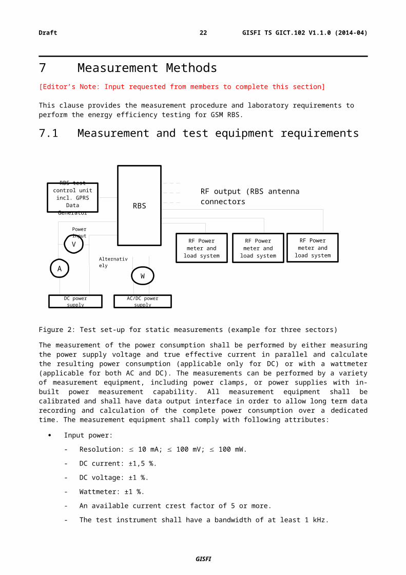
RBS
RBS test control unit incl. GPRS Data Generator
RF output (RBS antenna connectors
DC power supply
A
V
Power input
Alternatively
AC/DC power supply
W
RF Power meter and load system
RF Power meter and load system
RF Power meter and load system
7 Measurement Methods[Editor’s Note: Input requested from members to complete this section]
This clause provides the measurement procedure and laboratory requirements to perform the energy efficiency testing for GSM RBS.
7.1 Measurement and test equipment requirements
Figure 2: Test set-up for static measurements (example for three sectors)
The measurement of the power consumption shall be performed by either measuring the power supply voltage and true effective current in parallel and calculate the resulting power consumption (applicable only for DC) or with a wattmeter (applicable for both AC and DC). The measurements can be performed by a variety of measurement equipment, including power clamps, or power supplies with in-built power measurement capability. All measurement equipment shall be calibrated and shall have data output interface in order to allow long term data recording and calculation of the complete power consumption over a dedicated time. The measurement equipment shall comply with following attributes:
Input power:
- Resolution: 10 mA; 100 mV; 100 mW.
- DC current: ±1,5 %.
- DC voltage: ±1 %.
- Wattmeter: ±1 %.
- An available current crest factor of 5 or more.
- The test instrument shall have a bandwidth of at least 1 kHz.
RF Power Meter
- RF power options 5W, 20W, 50W, 100W
- RF output power: ±0,4 dB.
- Bandwidth: Broadband
GISFI
GISFI TS GICT.102 V1.1.0 (2014-04)18Draft

[Editor’s Note: Test setup and measurement equipment requirements as per [10]]
7.2 UE Performance RequirementsThe UE performance requirements as stated in 3GPP TS 45.005 on radio transmission and reception [6] shall be met. Only UEs that meet or exceed the required reference sensitivity shall be used for the test. The acceptable level of UE receiver sensitivity is specified in 3GPP TS 51.021 [7].
7.3 RBS ConfigurationThe RBS shall be tested under normal test conditions according to the information accompanying the equipment. The RBS, test configuration and mode of operation (baseband, control and RF part of the RBS as well as the software and firmware) shall represent the normal intended use and shall be recorded in the test report.
In case of multiple configurations of RBS a configuration with 3 sectors shall be used. The connection to the simulator via the RBS controller interface shall be an electrical or optical cable-based interface (e.g. PCM, SDH, and Ethernet) which is commercially offered along with the applied RBS configuration. Additional power consuming features like battery loading shall be switched off.
Downlink ciphering on the air-interface shall be used. The Power saving features, used software and hardware version have to be listed in the measurement report. The measurement report shall mention the configuration of the RBS including the type of RF signal combining (antenna network combining, air combining or multi-carrier).
7.4 Environmental ConditionsFor the power consumption measurements the environmental conditions under which the RBS has to be tested are defined as follows:
Table 1: RBS environmental conditions
Condition Minimum MaximumBarometric pressure 86 kPa (860 mbar) 106 kPa (1050 mbar)Relative Humidity 20 % 85 %Vibration NegligibleTemperature Static: +25 °C and +40 °C
Temperature accuracy ±2 °C
In the RBS equipment level energy efficiency measurements, the power consumption of the air cooling equipment at the site is not considered for computation of the metric. Thus, in the absence of a climate controlled chamber within which the tests may be performed, all measurements shall be performed at an ambient room temperature of +25 °C.
7.5 Power supplyFor measurements of the RBS power consumption the following operating voltage value shall be used (for non standard power supply voltages one should use operating voltage with 2,5 % tolerances).
For nominal value and operating value shall be according for AC testing to [8] and DC testing to [9].
The frequency of the power supply corresponding to the AC mains shall be according to [8].
GISFI
GISFI TS GICT.102 V1.1.0 (2014-04)19Draft

7.6 Measurement Procedure[Editor’s Note: Input requested from members to complete this section]
7.6.1 Static test and measurement procedureThe power consumption measurements shall be performed when stable temperature conditions inside the equipment are reached. For this purpose the RBS shall be placed in the environmental conditions for minimum two hours with a minimum operation time of one hour before doing measurements. Measurement results shall be captured earliest when the equipment including the selected load is in stable operating conditions as specified in Section 7.4.
The RF output powers as well as the corresponding power consumptions of the RBS shall be measured with respect to the RF output power levels which are needed to fulfill the requirements from the reference networks as well as the traffic profiles described in Section 6.2. The reference point for the RF output measurements is the antenna connector of the RBS. The power consumption of the RBS as well as the RF output power shall be given in Watts.
1. Identify RBS basic parameters for test setup 2. List RBS configuration and traffic load(s) for measurements 3. Configure the RBS according to the appropriate reference configurations listed in Section 64. Connect the RBS according to the test setup and allow the system to stabilize5. Measure RBS equipment power consumption for required load levels.
a. The recorded throughput is the summation of the throughput for all antenna ports on all sectors and the input power is the total input power consumed by the entire integrated RBS.
6. For GSM RBS equipment, compute the energy efficiency metric as per Section 6.2:a. Calculate EE metric for voice only traffic for GSM configurationb. Calculate EE metric for data only traffic for GPRS configurationc. Calculate EE metric for mixed traffic profile for GSM/GPRS configuration
7. Collect and report the measurement results according to guidelines in Section 8.
GISFI
GISFI TS GICT.102 V1.1.0 (2014-04)20Draft

7.6.2 Dynamic test and measurement procedure[Editor’s Note: Input requested from members to complete this section]
GISFI
GISFI TS GICT.102 V1.1.0 (2014-04)21Draft
8 Measurement Report[Editor’s Note: Input requested from members to complete this section]
The results of the assessments shall be reported in accordance with specific instructions as per this document. A list of reference parameters, measurement conditions, test results and derived calculation results which are to be reported is given in Annex A. Further guidelines on the test report may be found in GISFI TS GICT.100; Metrics and Measurement Methods for Energy Efficiency: General Requirements [5].
GISFI
GISFI TS GICT.102 V1.1.0 (2014-04)22Draft
Annex A (normative):
Measurement Reports
[Editor’s Note: Input requested from members to complete this section, the following tables are based on ETSI 102 706 recommendation]
Table A.1: Test general information
1) Document reference and version2) Date of the test3) Version of TS GICT.102 used4) Location of the test5) Name of test organization and responsible person6) Tested equipment
6.1) Tested HW unit names and serial numbers6.2) Software version of tested equipment
7) List of used measurements equipment including type, serial number and calibration information
Table A.2: GSM RBS reference parameters to be reported
Parameter Value Unit1) GSM RBS configuration
1.1) Number of sectors1.2) Number of Carriers per sector
1.2.1)Number of carriers the RBS is able to support
1.2.2)Number of carriers, for which the HW was enabled (independent whether or not the carriers were used for the test)
1.2.3) Number of carriers used during the test1.3) RX diversity1.4) Type of RF signal combining1.5) Remote Radio Head (Yes/No)
2) Frequency2.1) Downlink band MHz2.2) Uplink band MHz2.3) Chanel bandwidth MHz
3) Environment3.1) Temperature range °C
4) Features4.1) Power saving features (implemented
independently in RBS)4.2) Coverage and capacity features
GISFI
GISFI TS GICT.102 V1.1.0 (2014-04)23Draft

Table A.3: Measurements conditions and results to be reported in static method
Parameter Test case 25 °C Test case 40 °C Unit1) Test environment
1.1) Temperature during test (measured) °C
1.2) Pressure (measured) kPa1.3) Relative humidity (measured)
2) Downlink frequency used at test2.1) Centre frequency of low end channel MHz2.2) Centre frequency of middle channel MHz2.3) Centre frequency of high end channel MHz
3) Supply voltage3.1) DC voltage (measured) V3.2) AC voltage (measured, phase to neutral) V3.3) AC Frequency (measured) Hz
4) Static power consumption (measured)4.1) Busy hour load W4.2) Medium load W4.3) Low load W
5) TX output power (pilot signal only) W6) RX receiver sensitivity at middle channel dBm
Table A.4: Calculation results to be reported in static method
Parameter Value Unit1) Pequipment of integrated RBS power consumption at 25 °C W2) Pequipement of integrated RBS power consumption at
40 °CW
3) Pequipement of distributed RBS power consumption at 25 °C W3.1) Pequipement of distributed RBS power consumption at 25 °C for central part W3.2) Pequipement of distributed RBS power consumption at 25 °C for remote part W
4) Pequipement of distributed RBS power consumption at 40 °C W4.1) Pequipement of distributed RBS power consumption at 40 °C for central part W4.2) Pequipement of distributed RBS power consumption at 40 °C for remote part W
Table A.5: Energy Efficiency metric to be reported in static method
Parameter Value Unit1) EE of integrated GSM RBS for voice only traffic profile Erlangs/W2) EE of distributed GSM RBS for voice only traffic profile Erlangs/W3) EE of integrated GSM RBS for data only traffic profile (GPRS mode) Kbps/W4) EE of distributed GSM RBS for data only traffic profile (GPRS mode) Kbps/W5) EE of integrated GSM RBS for combined voice and data traffic profile Erlangs + Kbps / W6) EE of distributed GSM RBS for combined voice and data traffic profile Erlangs + Kbps / W
GISFI
GISFI TS GICT.102 V1.1.0 (2014-04)24Draft

Annex B: Change history
Change historyDate TSG # TSG Doc. CR Rev Subject/Comment Old New2013-11-25
Initial TOC and skeleton 0.0 0.1
2014-03-04
Content revision 0.1 0.2
2014-04-04
Sections 1 to 7 major content addition 0.2 0.3
2014-04-10
Section 8 and Annexure A updated 0.3 0.4
GISFI
GISFI TS GICT.102 V1.1.0 (2014-04)25Draft