Embed Size (px)
Citation preview
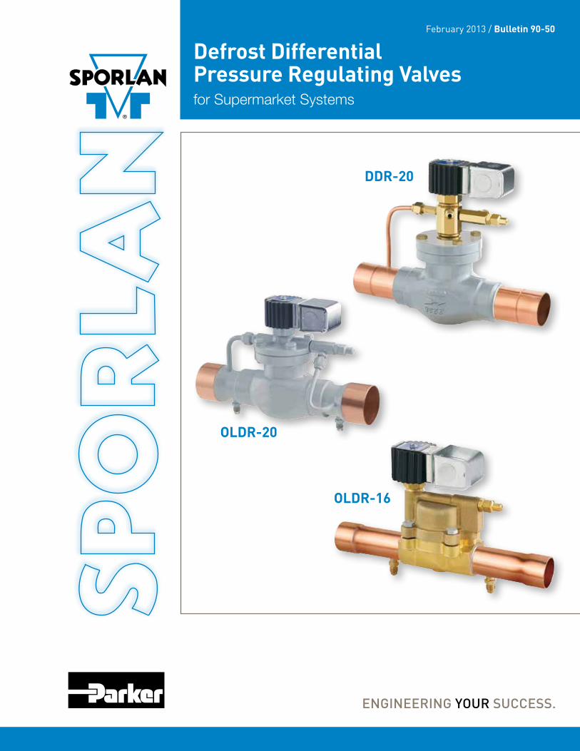
Defrost Differential Pressure Regulating Valvesfor Supermarket Systems
February 2013 / Bulletin 90-50
DDR-20
OLDR-16
OLDR-20

Page 2 – Bulletin 90-50
BENEFITS ■ Able to maintain a differential pressure between
the defrost header and the liquid header, allowing reverse flow during the defrost cycle.
■ Combines a liquid differential valve and a solenoid valve into one component, thus reducing piping costs.
■ Ability to adjust the differential setting from 5 to 50 psid.
In many supermarket applications refrigerant gas from the dis-charge line, or from the top of the receiver, is used for defrost. This method of defrost diverts a portion of the hot gas or latent gas (from the top of the receiver) to the suction line, and back through the evaporator being defrosted. The gas condenses in the evaporator and flows in reverse, through a check valve, around the TEV and liquid line solenoid valve. Liquid refrigerant then flows to the liquid header where it is distributed to evaporators not in the defrost cycle. In order for reverse flow to occur, the pressure of the defrost header must be greater than the pressure of the liquid header. The difference in pressure is known as the defrost differential.
Several methods are used to obtain the defrost differential. A common liquid line method is to install a differential check
Figure 2Differential
Figure 4Full Open
valve in parallel with a solenoid valve between the receiver and the liquid header. When the solenoid valve is closed dur-ing defrost, it allows the differential check valve to control the receiver at a greater pressure than the liquid header.
Sporlan offers the (O)LDR-16 and (O)LDR-20 valves for this application. The (O)LDR valve combines the features of the liquid differential check valve and the solenoid valve into a single component and are commonly called the liquid line dif-ferential valve.
A discharge line method is to install a discharge differential pressure regulating valve in the discharge line before the con-denser. In order for the reverse flow of hot gas to occur, the pressure of the discharge gas (defrost header) must be greater than the pressure of the receiver (liquid header). Sporlan offers the DDR-20 for this application. A solenoid feature allows the valve to control the differential when the coil is de-energized and to operate full open when the coil is energized.
OPERATIONOLDR - Valve Design & Operation The (O)LDR is designed to maintain a differential pressure between the receiver and the liquid header. A pilot differential valve controls the (O)LDR by varying the pressure on top of
Figure 1Full Open
Figure 3Differential
LDR
-16
OLD
R-1
6
MKC-1 Coil
OMKC-1 Coil
P2 Spring
P2 Spring
Pilot Port
Pilot Port
Pilot Differential Valve
Pilot Differential Valve
Pilot Differential Valve
Pilot Differential Valve
Strainer
Strainer
P3
P3
P1
P1
MKC-1 Coil
OMKC-1 Coil
P2 Spring
P2 Spring
Pilot Port
Pilot Port
P1
P1
Strainer
Strainer
P3
P3
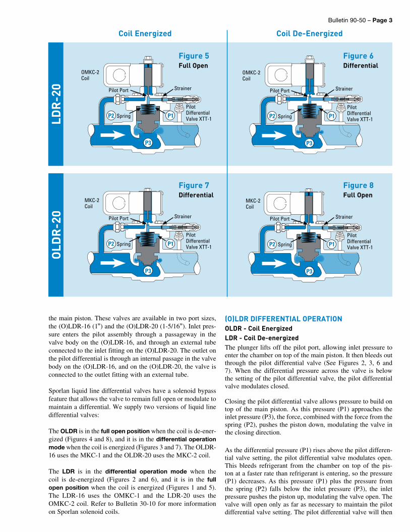
Coil Energized Coil De-Energized
Bulletin 90-50 – Page 3
the main piston. These valves are available in two port sizes, the (O)LDR-16 (1”) and the (O)LDR-20 (1-5/16”). Inlet pres-sure enters the pilot assembly through a passageway in the valve body on the (O)LDR-16, and through an external tube connected to the inlet fitting on the (O)LDR-20. The outlet on the pilot differential is through an internal passage in the valve body on the (O)LDR-16, and on the (O)LDR-20, the valve is connected to the outlet fitting with an external tube.
Sporlan liquid line differential valves have a solenoid bypass feature that allows the valve to remain full open or modulate to maintain a differential. We supply two versions of liquid line differential valves:
The OLDR is in the full open position when the coil is de-ener-gized (Figures 4 and 8), and it is in the differential operation mode when the coil is energized (Figures 3 and 7). The OLDR-16 uses the MKC-1 and the OLDR-20 uses the MKC-2 coil.
The LDR is in the differential operation mode when the coil is de-energized (Figures 2 and 6), and it is in the full open position when the coil is energized (Figures 1 and 5). The LDR-16 uses the OMKC-1 and the LDR-20 uses the OMKC-2 coil. Refer to Bulletin 30-10 for more information on Sporlan solenoid coils.
Figure 6Differential
Figure 8Full Open
Figure 5Full Open
Figure 7Differential
LDR
-20
OLD
R-2
0OMKC-2 Coil
MKC-2 Coil
OMKC-2 Coil
MKC-2 Coil
P2 Spring
P2 Spring
P2 Spring
P2 Spring
Pilot Port
Pilot Port
Pilot Port
Pilot Port
Pilot Differential Valve XTT-1
Pilot Differential Valve XTT-1
Pilot Differential Valve XTT-1
Pilot Differential Valve XTT-1
Strainer
Strainer
Strainer
Strainer
P3
P3
P3
P3
P1
P1
P1
P1
(O)LDR DIFFERENTIAL OPERATIONOLDR - Coil EnergizedLDR - Coil De-energized The plunger lifts off the pilot port, allowing inlet pressure to enter the chamber on top of the main piston. It then bleeds out through the pilot differential valve (See Figures 2, 3, 6 and 7). When the differential pressure across the valve is below the setting of the pilot differential valve, the pilot differential valve modulates closed.
Closing the pilot differential valve allows pressure to build on top of the main piston. As this pressure (P1) approaches the inlet pressure (P3), the force, combined with the force from the spring (P2), pushes the piston down, modulating the valve in the closing direction.
As the differential pressure (P1) rises above the pilot differen-tial valve setting, the pilot differential valve modulates open. This bleeds refrigerant from the chamber on top of the pis-ton at a faster rate than refrigerant is entering, so the pressure (P1) decreases. As this pressure (P1) plus the pressure from the spring (P2) falls below the inlet pressure (P3), the inlet pressure pushes the piston up, modulating the valve open. The valve will open only as far as necessary to maintain the pilot differential valve setting. The pilot differential valve will then
Coil Energized Coil De-Energized
Page 4 – Bulletin 90-50
P3
To Receiver
200 Mesh Strainer
Port A
PilotDifferential Valve XUL
P1
Port B
P2 (Spring)
Fitting “C” to Suction To Receiver
Port A
PilotDifferential Valve XUL
Port B
Fitting “C” to Suction
P3
P1
P2 (Spring)
200 Mesh Strainer
Figure 10Full Open
Figure 9Differential
DD
R-2
0 Fitting “C”
Top View
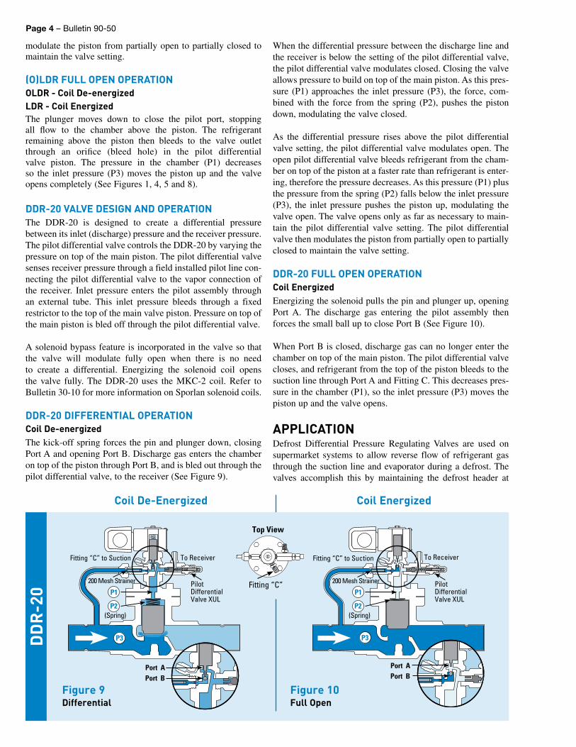
modulate the piston from partially open to partially closed to maintain the valve setting.
(O)LDR FULL OPEN OPERATIONOLDR - Coil De-energizedLDR - Coil EnergizedThe plunger moves down to close the pilot port, stopping all flow to the chamber above the piston. The refrigerant remaining above the piston then bleeds to the valve outlet through an orifice (bleed hole) in the pilot differential valve piston. The pressure in the chamber (P1) decreases so the inlet pressure (P3) moves the piston up and the valve opens completely (See Figures 1, 4, 5 and 8).
DDR-20 VALVE DESIGN AND OPERATIONThe DDR-20 is designed to create a differential pressure between its inlet (discharge) pressure and the receiver pressure. The pilot differential valve controls the DDR-20 by varying the pressure on top of the main piston. The pilot differential valve senses receiver pres sure through a field installed pilot line con-necting the pilot differential valve to the vapor connection of the receiver. Inlet pressure enters the pilot assembly through an external tube. This inlet pressure bleeds through a fixed restrictor to the top of the main valve piston. Pressure on top of the main piston is bled off through the pilot differential valve.
A solenoid bypass feature is incorporated in the valve so that the valve will modulate fully open when there is no need to create a differential. Energizing the solenoid coil opens the valve fully. The DDR-20 uses the MKC-2 coil. Refer to Bulletin 30-10 for more information on Sporlan solenoid coils.
DDR-20 DIFFERENTIAL OPERATIONCoil De-energizedThe kick-off spring forces the pin and plunger down, closing Port A and opening Port B. Discharge gas enters the chamber on top of the piston through Port B, and is bled out through the pilot differential valve, to the receiver (See Figure 9).
When the differential pressure between the dis charge line and the receiver is below the setting of the pilot differential valve, the pilot differential valve mod u lates closed. Closing the valve allows pressure to build on top of the main piston. As this pres-sure (P1) ap proach es the inlet pressure (P3), the force, com-bined with the force from the spring (P2), pushes the piston down, modulating the valve closed.
As the differential pressure rises above the pilot differential valve setting, the pilot differential valve modulates open. The open pilot differential valve bleeds refrigerant from the cham-ber on top of the pis ton at a faster rate than refrigerant is enter-ing, therefore the pressure decreases. As this pressure (P1) plus the pressure from the spring (P2) falls below the inlet pressure (P3), the inlet pressure pushes the piston up, modulating the valve open. The valve opens only as far as necessary to main-tain the pilot differential valve setting. The pilot differ en tial valve then mod u lates the piston from partially open to partially closed to maintain the valve setting.
DDR-20 FULL OPEN OPERATIONCoil En er gizedEnergizing the solenoid pulls the pin and plunger up, opening Port A. The discharge gas entering the pilot assembly then forces the small ball up to close Port B (See Figure 10).
When Port B is closed, discharge gas can no longer enter the chamber on top of the main piston. The pilot differential valve closes, and refrigerant from the top of the piston bleeds to the suction line through Port A and Fitting C. This decreases pres-sure in the cham ber (P1), so the inlet pressure (P3) moves the piston up and the valve opens.
APPLICATIONDefrost Differential Pressure Regulating Valves are used on supermarket systems to allow reverse flow of refrigerant gas through the suction line and evap o ra tor during a defrost. The valves accomplish this by maintaining the defrost header at
Coil EnergizedCoil De-Energized
Bulletin 90-50 – Page 5
TEV
TEV
ORIHead Pressure
Control Valve
ReplaceableCatch-All
See•All
Liquid LineSolenoid Valve
Liquid Line SolenoidValve with Check ValveFeature (CE Series)
Check Valve
Check Valve
Check Valve
Check Valve
Distributor
Def
rost
Hea
der
Suct
ion
Hea
der
Type ORD-4 Discharge Bypass ValveReceiver Pressurization Valve
8D, 12D, 16D,Heat Reclaim ValveDDR-20 Discharge
Differential Regulator
OCV Oil Check Valve
ReplaceableOil Filter Oil Separator
POROil Reservoir
OL-60Oil LevelControl
CDS Step MotorEvaporator Control Valve
2-Way Solenoid Defrost Valve
2-Way Solenoid Defrost Valve
SORIT EvaporatorPressure Regulator
Reclaim CondenserPump-out Solenoid Valve (normally open)
Restrictor of some type may be required
ReplaceableSuction Filter
Liquid Header
SuctionDischarge
OilLiquid Evaporator
Evaporator
Normal Condenser
Reclaim Condenser
PIPING KEY
Receiver
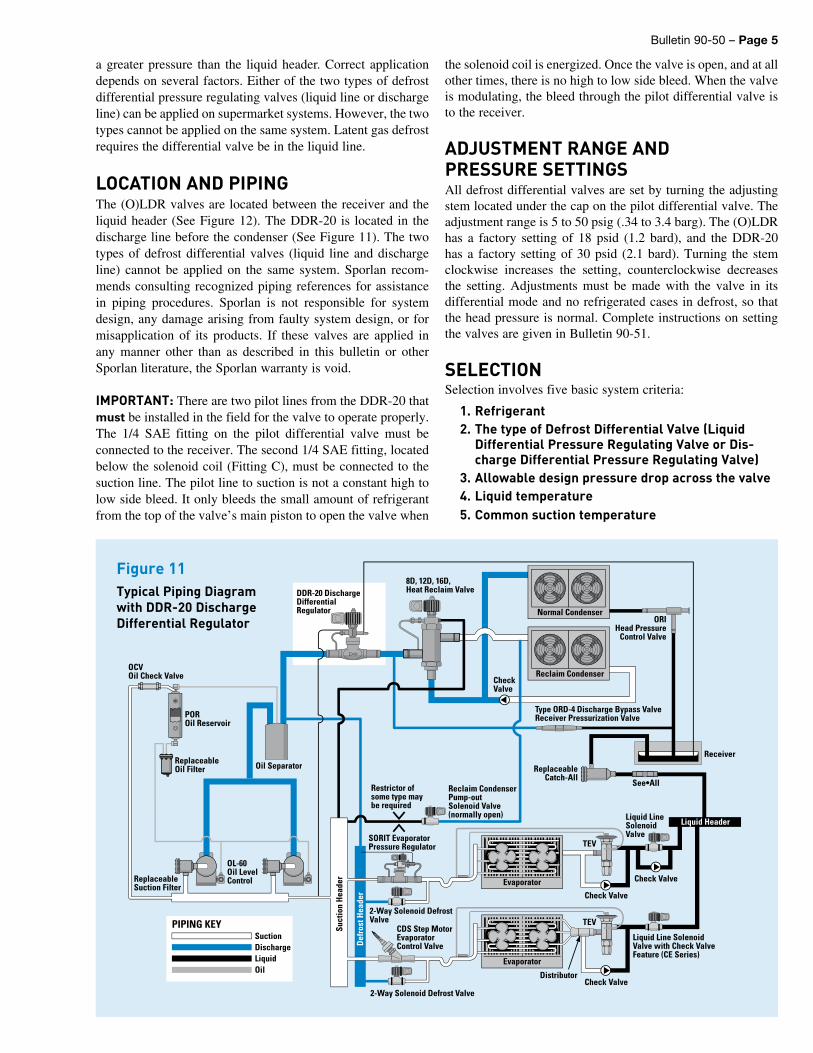
Figure 11Typical Piping Diagram with DDR-20 Discharge Differential Regulator
a greater pressure than the liquid header. Correct application depends on several factors. Either of the two types of defrost differential pres sure regulating valves (liquid line or discharge line) can be applied on supermarket systems. However, the two types cannot be applied on the same system. Latent gas defrost requires the differential valve be in the liquid line.
LOCATION AND PIPINGThe (O)LDR valves are located between the receiver and the liquid header (See Figure 12). The DDR-20 is lo cat ed in the discharge line before the condenser (See Figure 11). The two types of defrost differential valves (liquid line and discharge line) cannot be applied on the same system. Sporlan recom-mends consulting recognized piping references for assistance in piping procedures. Sporlan is not responsible for system design, any damage arising from faulty system design, or for misapplication of its products. If these valves are applied in any manner other than as described in this bulletin or other Sporlan literature, the Sporlan warranty is void.
IMPORTANT: There are two pilot lines from the DDR-20 that must be installed in the field for the valve to operate properly. The 1/4 SAE fitting on the pilot differential valve must be connected to the receiver. The second 1/4 SAE fitting, located below the solenoid coil (Fitting C), must be connected to the suc tion line. The pilot line to suction is not a constant high to low side bleed. It only bleeds the small amount of refrigerant from the top of the valve’s main piston to open the valve when
the solenoid coil is energized. Once the valve is open, and at all other times, there is no high to low side bleed. When the valve is modulating, the bleed through the pilot differential valve is to the receiver.
ADJUSTMENT RANGE ANDPRESSURE SETTINGSAll defrost differential valves are set by turning the adjusting stem located under the cap on the pilot differential valve. The adjustment range is 5 to 50 psig (.34 to 3.4 barg). The (O)LDR has a factory setting of 18 psid (1.2 bard), and the DDR-20 has a factory setting of 30 psid (2.1 bard). Turning the stem clockwise increases the setting, counterclockwise decreases the setting. Adjustments must be made with the valve in its differential mode and no refrigerated cases in defrost, so that the head pressure is normal. Complete instructions on setting the valves are given in Bulletin 90-51.
SELECTIONSelection involves five basic system criteria:
1. Refrigerant2. The type of Defrost Differential Valve (Liquid
Differential Pressure Regulating Valve or Dis-charge Differential Pressure Regulating Valve)
3. Allowable design pressure drop across the valve4. Liquid temperature5. Common suction temperature
Page 6 – Bulletin 90-50
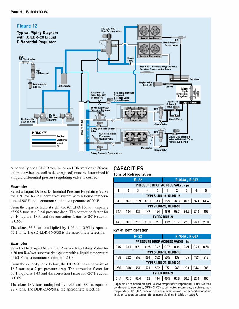
Figure 12Typical Piping Diagram with (O)LDR-20 Liquid Differential Regulator
TEV
TEV
ORI Head Pressure
Control Valve
Replaceable Catch-All
See•All
Liquid Line Solenoid Valve
Liquid Line Solenoid Valve with Check Valve Feature (CE Series)
Check Valve
Check Valve
Check Valve
Check Valve
Distributor
Def
rost
Hea
der
Suct
ion
Hea
der
Type ORD-4 Discharge Bypass ValveReceiver Pressurization Valve
8D, 12D, 16D, Heat Reclaim Valve
OCV Oil Check Valve
Replaceable Oil Filter Oil Separator
POROil Reservoir
OL-60Oil LevelControl
CDS Step MotorEvaporator Control Valve
2-Way Solenoid Defrost Valve
2-Way Solenoid Defrost Valve
SORIT EvaporatorPressure Regulator
Reclaim CondenserPump-out Solenoid Valve (normally open)
Restrictor of some type may be required
ReplaceableSuction Filter
Liquid Header
Suction Discharge
Oil Liquid Evaporator
Evaporator
Normal Condenser
Reclaim Condenser
PIPING KEY
Receiver
(O)LDRLiquid
DifferentialRegulator
A normally open OLDR version or an LDR ver sion (differen-tial mode when the coil is de-energized) must be determined if a liquid differential pressure regulating valve is desired.
Example:Select a Liquid Defrost Differential Pressure Regulating Valve for a 50 ton R-22 supermarket system with a liquid tempera-ture of 90°F and a common suction temperature of 20°F.
From the capacity table at right, the (O)LDR-16 has a capacity of 56.8 tons at a 2 psi pressure drop. The correction factor for 90°F liquid is 1.06, and the correction factor for 20°F suction is 0.95.
Therefore, 56.8 tons multiplied by 1.06 and 0.95 is equal to 57.2 tons. The (O)LDR-16-5/50 is the appropriate selection.
Example:Select a Discharge Differential Pressure Regulating Valve for a 20 ton R-404A supermarket system with a liquid temperature of 60°F and a common suction of -20°F.
From the capacity table below, the DDR-20 has a capacity of 18.7 tons at a 2 psi pres sure drop. The correction factor for 60°F liquid is 1.43 and the correction factor for -20°F suction is 0.85.
Therefore 18.7 tons multiplied by 1.43 and 0.85 is equal to 22.7 tons. The DDR-20-5/50 is the appropriate selection.
R- 22 R-404A / R-507PRESSURE DROP ACROSS VALVE - psi
1 2 3 4 5 1 2 3 4 5TYPES LDR-16, OLDR-16
38.9 56.8 70.9 83.0 93.7 25.5 37.3 46.5 54.4 61.4TYPES LDR-20, OLDR-20
73.4 104 127 147 164 48.6 68.7 84.2 97.3 109TYPES DDR-20
14.6 20.6 25.1 29.0 32.3 13.2 18.7 22.8 26.3 29.3
R- 22 R-404A / R-507PRESSURE DROP ACROSS VALVE - bar
0.07 0.14 0.21 0.28 0.35 0.07 0.14 0.21 0.28 0.35TYPES LDR-16, OLDR-16
138 202 252 294 332 90.5 132 165 193 218TYPES LDR-20, OLDR-20
260 368 451 521 582 172 243 298 344 385TYPES DDR-20
51.4 72.5 88.4 102 114 46.5 65.8 80.3 92.6 103Capacities are based on 40°F (4.4°C) evaporator temperature, 100°F (37.8°C) condenser temperature, 25°F (-3.9°C) superheated return gas, discharge gas temperature 50°F (10°C) above isentropic compression. For capacities at other liquid or evaporator tem per a tures use multipliers in table on page 7.
CAPACITIESTons of Refrigeration
kW of Refrigeration
Bulletin 90-50 – Page 7
EVAPORATOR TEMPERATURE °F-40 -30 -20 -10 0 10 20 30 40
MULTIPLIER 0.83 0.83 0.85 0.88 0.91 0.93 0.95 0.98 1.00
EVAPORATOR TEMPERATURE °C-40 -35 -30 -25 -20 -15 -10 -5 0 5
MULTIPLIER 0.89 0.90 0.91 0.93 0.94 0.95 0.97 0.98 0.99 1.00
DESIGNATION / ORDERING INSTRUCTIONSSelect from the capacity table above. When ordering be sure to give complete valve designation including voltage and cycles.
(O) LDR – 16 – 5/50 – 1-3/8 ODF – 120/50-60
NormallyOpen
Liquid DifferentialRegulator
Valve Size
AdjustmentRange - psi
Connections -Inches
Electrical Specifications
DDR – 20 – 5/50 – 1- 5/8 ODF – 120/50-60Discharge Differential
Regulator Valve Size AdjustmentRange - psi
Connections -Inches
Electrical Specifications
OLDR
DDR
EVAPORATOR TEMPERATURE CORRECTION FACTORS
VALVE TYPE PORT SIZE Inches (mm)
DIFFERENTIAL SETPOINT RANGE
CONNECTIONS - Inches Inlet x Outlet COIL
WEIGHT - lbs. (kg)*Net Shipping
OLDR-16 1(25.4)
5/50 psi(.34 / 3.4 bar)
1-1/8 ODF x 1-1/8 ODF or1-3/8 ODF x 1-3/8 ODF
MKC-1 4 (1.8) 5 (2.3)LDR-16 OMKC-1 4 (1.8) 5 (2.3)
OLDR-20 1-5/16(33.3)
1-5/8 ODF x 1-5/8 ODF or2-1/8 ODF x 2-1/8 ODF
MKC-2 9 (4.1) 10.5 (4.8)LDR-20 OMKC-2 9 (4.1) 10.5 (4.8)DDR-20 1-5/16 (33.3) 1-5/8 ODF x 1-5/8 ODF MKC-2 9.5 (4.3) 10.5 (4.8)
*Add 1 pound for solenoid coil.
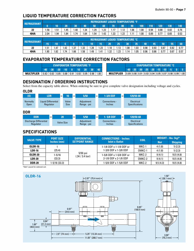
SPECIFICATIONS
REFRIGERANTREFRIGERANT LIQUID TEMPERATURE °F
0 10 20 30 40 50 60 70 80 90 100 110 120 130 14022 1.56 1.51 1.45 1.40 1.34 1.29 1.23 1.17 1.12 1.06 1.00 0.94 0.88 0.82 0.76
404A 2.04 1.94 1.84 1.74 1.64 1.54 1.43 1.33 1.22 1.11 1.00 0.89 0.77 0.65 0.53
REFRIGERANTREFRIGERANT LIQUID TEMPERATURE °C
-15 -10 -5 0 5 10 15 20 25 30 35 40 45 50 55 6022 1.51 1.47 1.42 1.37 1.33 1.28 1.23 1.18 1.13 1.08 1.03 0.98 0.93 0.87 0.82 0.77
404A 1.90 1.82 1.74 1.66 1.58 1.49 1.41 1.32 1.23 1.14 1.05 0.96 0.86 0.77 0.67 0.57
LIQUID TEMPERATURE CORRECTION FACTORS
0.97”(24.6 mm)
1.50”(38.1 mm)
0.84”(21.3 mm)1.60”
(40.6 mm)
11.05” (280.7 mm)2.9” (74 mm) 5.25” (13.34 mm) 3.00”
(76.2 mm)
6.65”(168.9 mm)
2.97” (75.4 mm)OLDR-16

Page 8 – Bulletin 90-50
Bulletin 90-50 / 22013© 2013 Parker Hannifin Corporation.
⚠WARNING – USER RESPONSIBILITYFailure or improper selection or improper use of the products described herein or related items can cause death, personal injury and property damage.
This document and other information from Parker Hannifin Corporation, its subsidiaries and authorized distributors provide product or system options for further investigation by users having technical expertise.
The user, through its own analysis and testing, is solely responsible for making the final selection of the system and components and assuring that all performance, endurance, maintenance, safety and warning requirements of the application are met. The user must analyze all aspects of the application, follow applicable industry standards, and follow the information concerning the product in the current product catalog and in any other materials provided from Parker or its subsidiaries or authorized distributors.
To the extent that Parker or its subsidiaries or authorized distributors provide component or system options based upon data or specifications provided by the user, the user is responsible for determining that such data and specifications are suitable and sufficient for all applications and reasonably foreseeable uses of the components or systems.
For safety information see the Safety Guide at www.parker.com/safety or call 1-800-CParker.
OFFER OF SALEThe items described in this document are hereby offered for sale by Parker Hannifin Corporation, its subsidiaries or its authorized distributors. This offer and its acceptance are governed by the provisions stated in the detailed “Offer of Sale” available at www.parker.com.
FOR USE ON REFRIGERATION and/or AIR CONDITIONING SYSTEMS ONLYBulletin 90-50, February 2013 supersedes Bulletin 90-50, April 2004 and all prior publications.
11.06” (280.9 mm)4.41” (112.0 mm)2.035”
(51.7 mm)
1.78”(45.2 mm)
7.45”(189.2 mm)
6.99” (177.5 mm)
3.19” (81.0 mm)2.06”
(52.3 mm)
8.56”(217.4 mm)
4.50”(114.3 mm) 1.80”
(45.7 mm)
5.53” (140.5 mm) 5.53” (140.5 mm)
4.44”(111.8 mm)
3.19” (81.0 mm)2.06”
(52.3 mm)
5.93”(150.6 mm)
5.87”(149.1 mm)
OLDR-20
DDR-20
SPECIFICATIONS
Parker Hannifin CorporationSporlan Division206 Lange Drive • Washington, MO 63090 USAphone 636 239 1111fax 636 239 9130www.sporlan.com