Embed Size (px)
Citation preview
RACE Catalogue 30-10 UK / Página 1
22, 134a, 401A, 402A, 404A, 407C, 502, 507 Types B6 and E6
Series
The right solenoid valve
for any job
April 2010 / RACE Catalogue 30-10 UK
Solenoid Valves
RACE Catalogue 30-10 UK / Page 1
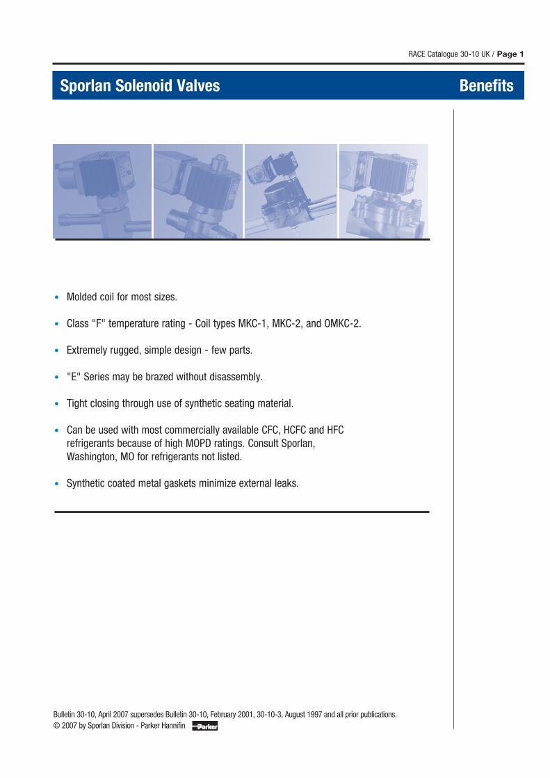
Sporlan Solenoid Valves Benefits
• Molded coil for most sizes.
• Class "F" temperature rating - Coil types MKC-1, MKC-2, and OMKC-2.
• Extremely rugged, simple design - few parts.
• "E" Series may be brazed without disassembly.
• Tight closing through use of synthetic seating material.
• Can be used with most commercially available CFC, HCFC and HFC
refrigerants because of high MOPD ratings. Consult Sporlan,
Washington, MO for refrigerants not listed.
• Synthetic coated metal gaskets minimize external leaks.
Bulletin 30-10, April 2007 supersedes Bulletin 30-10, February 2001, 30-10-3, August 1997 and all prior publications.
© 2007 by Sporlan Division - Parker Hannifin
Page 2 / RACE Catalogue 30-10 UK
SELECTION . . . . . . . . . . . . . . . . . . . . . . . . . . . . . . . . . . . . . . . . . . . . . . . . . . . . . . . . . . . . . . . . . 3
CAPACITIES
Liquid Line . . . . . . . . . . . . . . . . . . . . . . . . . . . . . . . . . . . . . . . . . . . . . . . . . . . . . . . . . . . . . . . 4
Suction Line . . . . . . . . . . . . . . . . . . . . . . . . . . . . . . . . . . . . . . . . . . . . . . . . . . . . . . . . . . . . . 6
Air & Water . . . . . . . . . . . . . . . . . . . . . . . . . . . . . . . . . . . . . . . . . . . . . . . . . . . . . . . . . . . . .19
Steam. . . . . . . . . . . . . . . . . . . . . . . . . . . . . . . . . . . . . . . . . . . . . . . . . . . . . . . . . . . . . . . . . . .19
Discharge Gas . . . . . . . . . . . . . . . . . . . . . . . . . . . . . . . . . . . . . . . . . . . . . . . . . . . . . . . . . . . 6
SPECIFICATIONS
Types A3, E3 and E5 Series . . . . . . . . . . . . . . . . . . . . . . . . . . . . . . . . . . . . . . . . . . . . . 8
Types B6 and E6 Series . . . . . . . . . . . . . . . . . . . . . . . . . . . . . . . . . . . . . . . . . . . . . . . . . 9
Types B9 and E9 Series . . . . . . . . . . . . . . . . . . . . . . . . . . . . . . . . . . . . . . . . . . . . . . . .10
Types B10 and E10 Series . . . . . . . . . . . . . . . . . . . . . . . . . . . . . . . . . . . . . . . . . . . . .11
Types B14 and E14 Series . . . . . . . . . . . . . . . . . . . . . . . . . . . . . . . . . . . . . . . . . . . . .12
Types B19 and E19 Series . . . . . . . . . . . . . . . . . . . . . . . . . . . . . . . . . . . . . . . . . . . . .13
Types B25 and E25 Series . . . . . . . . . . . . . . . . . . . . . . . . . . . . . . . . . . . . . . . . . . . . .14
Types E35 Series . . . . . . . . . . . . . . . . . . . . . . . . . . . . . . . . . . . . . . . . . . . . . . . . . . . . . . .15
Type E42 Series . . . . . . . . . . . . . . . . . . . . . . . . . . . . . . . . . . . . . . . . . . . . . . . . . . . . . . . .16
Built-In Check Valve Series . . . . . . . . . . . . . . . . . . . . . . . . . . . . . . . . . . . . . . . . . . . . .17
Industrial Solenoid Valves . . . . . . . . . . . . . . . . . . . . . . . . . . . . . . . . . . . . . . . . . . . . . .19
GENERAL . . . . . . . . . . . . . . . . . . . . . . . . . . . . . . . . . . . . . . . . . . . . . . . . . . . . . . . . . . . . . . . . . .21
DESIGN . . . . . . . . . . . . . . . . . . . . . . . . . . . . . . . . . . . . . . . . . . . . . . . . . . . . . . . . . . . . . . . . . . . .22
CONSTRUCTION DETAILS . . . . . . . . . . . . . . . . . . . . . . . . . . . . . . . . . . . . . . . . . . . . . . . . .23
NET and SHIPPING WEIGHTS. . . . . . . . . . . . . . . . . . . . . . . . . . . . . . . . . . . . . . . . . . . . . .23
ELECTRICAL SPECIFICATIONS. . . . . . . . . . . . . . . . . . . . . . . . . . . . . . . . . . . . . . . . . . . . .24
IDENTIFICATION . . . . . . . . . . . . . . . . . . . . . . . . . . . . . . . . . . . . . . . . . . . . . . . . . . . . . . . . . . .25
APPLICATION . . . . . . . . . . . . . . . . . . . . . . . . . . . . . . . . . . . . . . . . . . . . . . . . . . . . . . . . . . . . . .27
SOLENOID VALVES
Installation and Service Instructions . . . . . . . . . . . . . . . . . . . . . . . . . . . . . . . . . . . . . . . . . . . . Request Bulletin 30-11
3-Way Valves . . . . . . . . . . . . . . . . . . . . . . . . . . . . . . . . . . . . . . . . . . . . . . . . . . . . . . . . . . . . . . . . . Request Bulletin 30-20
NOT FOR USE WITH HAZARDOUS OR CORROSIVE FLUIDS
Contents Sporlan Solenoid Valves
Selection - Capacity Rating
RACE Catalogue 30-10 UK / Page 3
The following information should be available
when selecting a Sporlan Solenoid Valve:
• Refrigerant or fluid to be controlled.
• Capacity required.
• MOPD - Maximum Operating Pressure
Differential required.
• Electrical specifications - volts and cycles.
With this information, the correct valve can be
selected from the Selection Tables.
For Liquid Line capacity data, see Page 4 and 5
and individual specification pages.
For Suction Line capacity data, see capacity
tables Page 6 and 7.
For Discharge Gas capacity data, see capacity
tables Page 6 and 7.
All solenoid valves are tested and rated in accor-
dance with A.R.I. Standard No. 760-2001.
Experience
For more than sixty-five years Sporlan has pro-
vided sound engineering principles and crafts-
manship to produce top quality solenoid valves
and other flow control devices for the air condi-
tioning and refrigeration industry.
Continuing Research
Through continuing research Sporlan has
produced constant product improvements as
well as innovative designs. Examples of Sporlan’s
research developments include: synthetic coated
metal gaskets; solenoid pilot control; synthetic
seating; color coded lead wires; floating disc
construction; extended solder type connections;
Class "F" coil.
Peak Performance
To assure peak performance, Sporlan uses
thoroughly proven synthetic materials, result-
ing in lasting valve seat tightness. The high
MOPD ratings of most Sporlan Solenoid Valves
allow their use on any application using the
common refrigerants.
Unsurpassed Reliability
A combination of top quality materials used
in both the internal and external construction
ensures unsurpassed product reliability. This is
verified by periodic accelerated life tests.
Top Quality
Testing is performed during all phases of pro-
duction followed by 100% testing for body and
seat tightness, electrical characteristics and
valve operation.
Sporlan packaging protects this quality for the
ultimate user.
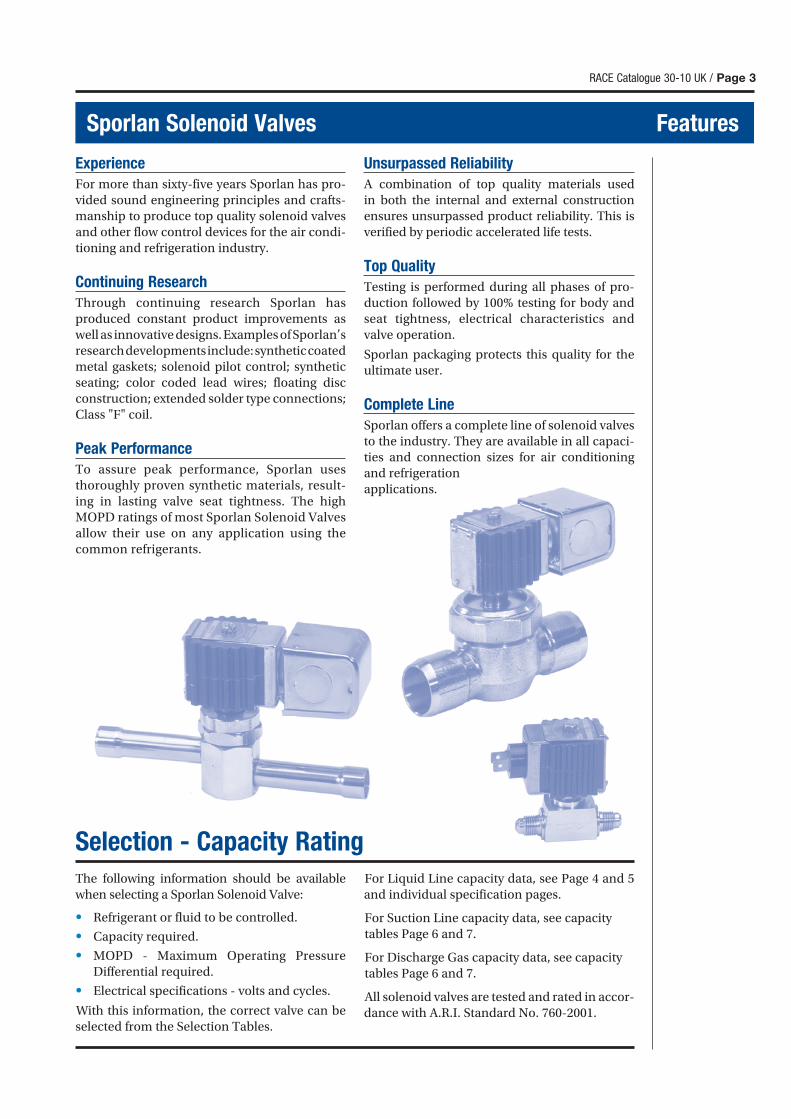
Complete Line
Sporlan offers a complete line of solenoid valves
to the industry. They are available in all capaci-
ties and connection sizes for air conditioning
and refrigeration
applications.
Sporlan Solenoid Valves Features
Page 4 / RACE Catalogue 30-10 UK
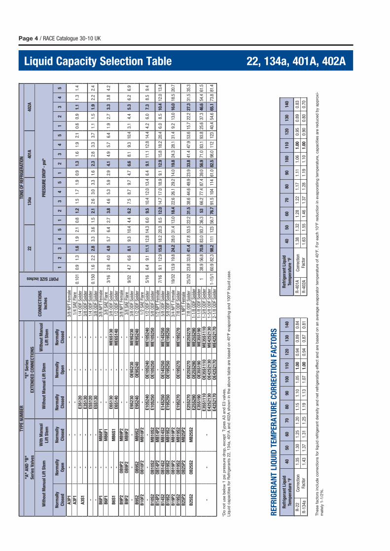
Liquid Capacity Selection Table 22, 134a, 401A, 402A
*Do
no
t use b
elo
w 1
psi p
ressure
dro
p,
excep
t T
yp
es A
3 a
nd
E3 v
alv
es.
Liq
uid
cap
acitie
s f
or
Refr
igera
nts
22,
134a,
401A
and
402A
sho
wn in t
he a
bo
ve t
ab
le a
re b
ased
on 4
0°F
evap
ora
ting
and
100°F
liq
uid
case.
These f
acto
rs inclu
de c
orr
ectio
ns f
or
liquid
refr
igera
nt
density a
nd
net
refr
igera
ting
eff
ect
and
are
based
on a
n a
vera
ge e
vap
ora
tor
tem
pera
ture
of
40°F
. F
or
each 1
0°F
red
uctio
n in e
vap
ora
ting
tem
pera
ture
, cap
acitie
s a
re r
ed
uced
by a
pp
roxi-
mate
ly 1
-1/2
%.
RE
FRIG
ER
AN
T L
IQU
ID T
EM
PE
RA
TU
RE
CO
RR
EC
TIO
N F
AC
TO
RS
TY
PE
NU
MB
ER
CO
NN
EC
TIO
NS
Inch
es
PORT SIZE inches
TON
S O
F R
EFR
IGER
ATIO
N"A
" A
ND
"B
"
Ser
ies
Va
lves
"E
" S
erie
s
EX
TE
ND
ED
CO
NN
EC
TIO
NS
2213
4a40
1A402A
Wit
ho
ut
Ma
nu
al
Lift
Ste
mW
ith
Ma
nu
al
Lift
Ste
mW
ith
ou
t M
an
ua
l Li
ft S
tem
Wit
hou
t M
an
ua
l
Lift
Ste
mP
RES
SU
RE
DR
OP
- p
si*
No
rma
lly
Clo
sed
No
rma
lly
Op
en
No
rma
lly
Clo
sed
No
rma
lly
Clo
sed
Norm
ally
Op
en
Norm
ally
Clo
sed
12
34
51
23
45
12
34
51
23
45
A3
P1
--
--
-3/8
NP
T Fe
mal
e
0.1
01
0.9
1.3
1.6
1.9
2.1
0.8
1.2
1.5
1.7
1.9
0.9
1.3
1.6
1.9
2.1
0.6
0.9
1.1
1.3
1.4
A3
F1-
--
--
1/4
SA
E Fl
are
A3
S1
--
E3
S1
20
--
1/4
OD
F S
olde
r-
-E
3S
13
0-
-3/8
OD
F S
olde
r-
--
E5
S1
20
--
1/4
OD
F S
olde
r0.1
50
1.6
2.2
2.8
3.3
3.6
1.5
2.1
2.6
3.0
3.3
1.6
2.3
2.8
3.3
3.7
1.1
1.5
1.9
2.2
2.4
--
-E
5S
13
0-
-3/8
OD
F S
olde
rB
6P
1-
MB
6P
1-
--
3/8
NP
T Fe
mal
e
3/1
62.
94.
04.
95.
76.
42.
73.
84.
65.
35.
92.
94.
14.
95.
76.
41
.92
.73.3
3.8
4.2
B6
F1-
MB
6F1
--
-3/8
SA
E Fl
are
B6
S1
-M
B6
S1
E6
S1
30
-M
E6S
130
3/8
OD
F S
olde
r-
E6
S1
40
-M
E6S
140
1/2
OD
F S
olde
rB
9P
2O
B9
P2
MB
9P
2-
--
3/8
NP
T Fe
mal
e
9/3
24.
76.
68.
19.
310
.44.
46.
27.
58.
79.
74.
76.
68.
19.
310
.43
.14
.45.3
6.2
6.9
B9
F2O
B9
F2M
B9
F2-
--
3/8
SA
E Fl
are
--
-E
9S
23
0O
E9S
230
ME
9S
230
3/8
OD
F S
olde
rB
9S
2O
B9
S2
MB
9S
2E
9S
24
0O
E9S
240
ME
9S
240
1/2
OD
F S
olde
rB
10
F2O
B1
0F2
MB
10
F2-
--
1/2
SA
E Fl
are
5/1
66.
49.
111
.112
.814
.36.
09.
510
.412
.013
.46.
49.
111
.112
.814
.44
.26
.07.3
8.5
9.4
--
-E
10
S2
40
OE
10S
240
ME
10S
240
1/2
OD
F S
olde
rB
10
S2
OB
10
S2
MB
10
S2
E1
0S
25
0O
E10S
250
ME
10S
250
5/8
OD
F S
olde
rB
14
P2
OB
14
P2
MB
14
P2
--
-1/2
NP
T Fe
mal
e7/1
69.
112
.915
.818
.220
.38.
512
.014
.717
.018
.99.
112
.915
.818
.220
.46
.08
.510
.412
.013
.4B
14
S2
OB
14
S2
MB
14
S2
E1
4S
25
0O
E14S
250
ME
14S
250
5/8
OD
F S
olde
rB
19
S2
OB
19
S2
MB
19
S2
E1
9S
25
0O
E19S
250
ME
19S
250
5/8
OD
F S
olde
r19/3
213
.919
.824
.228
.031
.413
.018
.422
.626
.129
.214
.019
.824
.328
.131
.49
.213
.016
.018
.520
.7B
19
P2
OB
19
P2
MB
19
P2
--
-3/4
NP
T Fe
mal
eB
19
S2
OB
19
S2
MB
19
S2
E1
9S
27
0O
E19S
270
ME
19S
270
7/8
OD
F S
olde
rB
25
P2
OB
25
P2
MB
25
P2
--
-1 N
PT
Fem
ale
25/3
223
.833
.841
.447
.853
.522
.231
.538
.644
.649
.923
.933
.841
.447
.953
.615
.722
.227
.331
.535
.3B
25
S2
OB
25
S2
MB
25
S2
E2
5S
27
0O
E25S
270
ME
25S
270
7/8
OD
F S
olde
rE
25
S2
90
OE
25S
290
ME
25S
290
1-1
/8 O
DF
Sol
der
--
-
E3
5S
19
0O
E35S
190
ME
35S
190
1-1
/8 O
DF
Sol
der
138
.956
.870
.983
.093
.736
.353
66.2
77.4
87.4
39.0
56.9
71.0
83.1
93.8
25.6
37.3
46.6
54.4
61.5
E3
5S
11
10
OE
35S
1110
ME
35S
1110
1-3
/8 O
DF
Sol
der
E4
2S
21
30
OE
42S
2130
ME
42S
2130
1-5
/8 O
DF
Sol
der
1-1
5/1
60.9
82.3
98.2
111
123
56.7
76.7
91.5
104
114
61.0
82.5
98.0
112
123
40.4
54.6
65.1
73.8
81.4
E4
2S
21
70
OE
42S
2170
ME
42S
2170
2-1
/8 O
DF
Sol
der R
efri
ger
an
t Li
qu
id
Tem
per
atu
re °
F40
50
60
70
80
90
100
110
120
130
140
R-4
01A
Cor
rect
ion
Fact
or
1.3
81.3
21.2
81.2
21.1
71.1
11.0
61.0
00.9
50.8
90.8
3
R-4
02A
1.6
31.5
51.4
61.3
71.2
81.1
91.1
01.0
00.9
00.8
00.7
0
Ref
rig
era
nt
Liq
uid
Tem
per
atu
re °
F4
05
06
07
08
09
0100
110
120
130
140
R-2
2C
orre
ctio
n
Fact
or
1.3
51
.30
1.2
51
.20
1.1
51
.10
1.0
51.0
00.9
40.8
90.8
4
R-1
34
a1
.43
1.3
71
.31
1.2
51
.19
1.1
31.0
71.0
00.9
40.8
70.8
1
RACE Catalogue 30-10 UK / Page 5
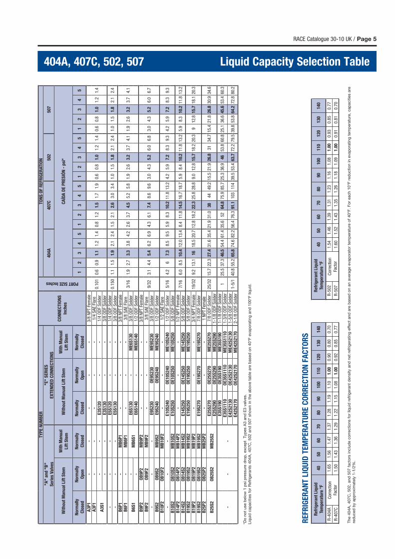
404A, 407C, 502, 507 Liquid Capacity Selection Table
TY
PE
NU
MB
ER
CO
NN
EC
TIO
NS
Inch
es
PORT SIZE Inches
TO
NS
OF
RE
FRIG
ER
ATIO
N"A
" a
nd
"B
"
Ser
ies
Va
lves
"E"
SE
RIE
S
EX
TE
ND
ED
CO
NN
EC
TIO
NS
404A
407C
502
507
Wit
ho
ut
Ma
nu
al
Lift
Ste
mW
ith
Ma
nu
al
Lift
Ste
mW
ith
ou
t M
an
ua
l Li
ft S
tem
Wit
h M
an
ua
l
Lift
Ste
mC
AÍD
A D
E P
RE
SIÓ
N -
psi
*
No
rma
lly
Clo
sed
No
rma
lly
Op
en
No
rma
lly
Clo
sed
No
rma
lly
Clo
sed
Norm
ally
Op
en
Norm
ally
Clo
sed
12
34
51
23
45
12
34
51
23
45
A3
P1
--
--
-3/8
NP
T Fe
mal
e
0.1
01
0.6
0.9
1.1
1.2
1.4
0.8
1.2
1.5
1.7
1.9
0.6
0.8
1.0
1.2
1.4
0.6
0.8
1.0
1.2
1.4
A3
F1-
--
--
1/4
SA
E Fl
are
A3
S1
--
E3
S1
20
--
1/4
OD
F S
olde
r-
-E
3S
13
0-
-3/8
OD
F S
olde
r-
--
E5
S1
20
--
1/4
OD
F S
olde
r0.1
50
1.1
1.5
1.9
2.1
2.4
1.5
2.1
2.6
3.0
3.4
1.0
1.5
1.8
2.1
2.4
1.0
1.5
1.8
2.1
2.4
--
-E
5S
13
0-
-3/8
OD
F S
olde
rB
6P
1-
MB
6P
1-
--
3/8
NP
T Fe
mal
e
3/1
61.
92.
73.
33.
84.
22.
63.
74.
55.
25.
81.
92.
63.
23.
74.
11.
92.
63.
23.
74.
1B
6F1
-M
B6
F1-
--
3/8
SA
E Fl
are
B6
S1
-M
B6
S1
E6
S1
30
-M
E6S
130
3/8
OD
F S
olde
r-
E6
S1
40
-M
E6S
140
1/2
OD
F S
olde
rB
9P
2O
B9
P2
MB
9P
2-
--
3/8
NP
T Fe
mal
e
9/3
23.
14.
45.
46.
26.
94.
36.
17.
48.
69.
63.
04.
35.
26.
06.
83.
04.
35.
26.
06.
7B
9F2
OB
9F2
MB
9F2
--
-3/8
SA
E Fl
are
--
-E
9S
23
0O
E9S
230
ME
9S
230
3/8
OD
F S
olde
rB
9S
2O
B9
S2
MB
9S
2E
9S
24
0O
E9S
240
ME
9S
240
1/2
OD
F S
olde
rB
10
F2O
B1
0F2
MB
10
F2-
--
1/2
SA
E Fl
are
5/1
64.
26
7.3
8.5
9.5
5.9
8.3
10.2
11.8
13.2
4.2
5.9
7.2
8.3
9.3
4.2
5.9
7.2
8.3
9.3
--
-E
10
S2
40
OE
10S
240
ME
10S
240
1/2
OD
F S
olde
rB
10
S2
OB
10
S2
MB
10
S2
E1
0S
25
0O
E10S
250
ME
10S
250
5/8
OD
F S
olde
rB
14
P2
OB
14
P2
MB
14
P2
--
-1/2
NP
T Fe
mal
e7/1
66.
08.
510
.412
.013
.48.
411
.814
.516
.718
.75.
98.
410
.211
.813
.25.
98.
310
.211
.813
.2B
14
S2
OB
14
S2
MB
14
S2
E1
4S
25
0O
E14S
250
ME
14S
250
5/8
OD
F S
olde
rB
19
S2
OB
19
S2
MB
19
S2
E1
9S
25
0O
E19S
250
ME
19S
250
5/8
OD
F S
olde
r19/3
29.
213
.116
18.5
20.7
12.8
18.2
22.3
25.8
28.8
9.0
12.8
15.7
18.2
20.3
912
.815
.718
.120
.3B
19
P2
OB
19
P2
MB
19
P2
--
-3/4
NP
T Fe
mal
eB
19
S2
OB
19
S2
MB
19
S2
E1
9S
27
0O
E19S
270
ME
19S
270
7/8
OD
F S
olde
rB
25
P2
OB
25
P2
MB
25
P2
--
-1 N
PT
Fem
ale
25/3
215
.722
.327
.431
.635
.421
.931
.038
4449
.215
.521
.926
.831
34.7
15.4
21.8
26.8
30.9
34.6
B2
5S
2O
B2
5S
2M
B2
5S
2E
25
S2
70
OE
25S
270
ME
25S
270
7/8
OD
F S
olde
rE
25
S2
90
OE
25S
290
ME
25S
290
1-1
/8 O
DF
Sol
der
--
-
E3
5S
19
0O
E35S
190
ME
35S
190
1-1
/8 O
DF
Sol
der
125
.537
.346
.554
.461
.435
.652
64.8
75.9
85.7
25.3
36.9
4653
.860
.825
.136
.645
.653
.460
.3E
35
S1
11
0O
E35S
1110
ME
35S
1110
1-3
/8 O
DF
Sol
der
E4
2S
21
30
OE
42S
2130
ME
42S
2130
1-5
/8 O
DF
Sol
der
1-5
/140
.855
.265
.874
.682
.256
.476
.391
.110
311
439
.553
.463
.772
.279
.539
.853
.864
.272
.880
.2E
42
S2
17
0O
E42S
2170
ME
42S
2170
2-1
/8 O
DF
Sol
der
*Do
no
t use b
elo
w 1
psi p
ressure
dro
p,
excep
t T
yp
es A
3 a
nd
E3 v
alv
es.
Liq
uid
cap
acitie
s f
or
Refr
igera
nts
404A
, 407C
, 502 a
nd
507 s
ho
wn in t
he a
bo
ve t
ab
le a
re b
ased
on 4
0°F
evap
ora
ting
and
100°F
liq
uid
.
The 4
04A
, 407C
, 502,
and
507 f
acto
rs inclu
de c
orr
ectio
ns f
or
liquid
refr
igera
nt
density a
nd
net
refr
igera
ting
eff
ect
and
are
based
on a
n a
vera
ge e
vap
ora
tor
tem
pera
ture
of
40°F
. F
or
each 1
0°F
red
uctio
n in e
vap
ora
ting
tem
pera
ture
, cap
acitie
s a
re
red
uced
by a
pp
roxim
ate
ly 1
-1/2
%.
RE
FRIG
ER
AN
T L
IQU
ID T
EM
PE
RA
TU
RE
CO
RR
EC
TIO
N F
AC
TO
RS
Ref
rig
era
nt
Liq
uid
Tem
per
atu
re °
F4
05
06
07
08
09
0100
110
120
130
140
R-4
04
AC
orre
ctio
n
Fact
or
1.6
51
.56
1.4
71
.37
1.2
81
.19
1.1
01.0
00.9
00.8
00.7
0
R-4
07
C1
.50
1.4
31
.36
1.2
91
.22
1.1
51
.08
1.0
00.9
20.8
50.7
7
Ref
rig
era
nt
Liq
uid
Tem
per
atu
re °
F40
50
60
70
80
90
100
110
120
130
140
R-5
02
Cor
rect
ion
Fact
or
1.5
41.4
61.3
91.3
11.2
31.1
61.0
81.0
00.9
30.8
50.7
7
R-5
07
1.6
01.5
21.4
31.3
51.2
61.1
81.0
91.0
00.9
10.8
10.7
0
Page 6 / RACE Catalogue 30-10 UK
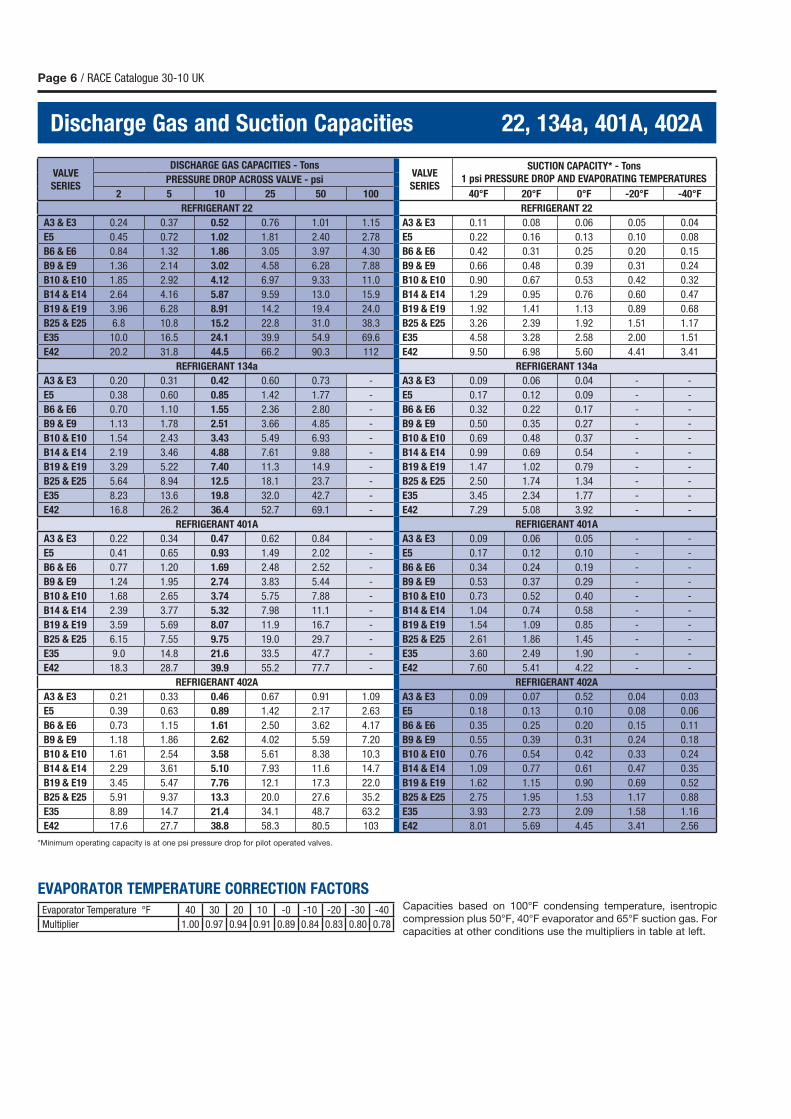
Discharge Gas and Suction Capacities 22, 134a, 401A, 402A
Capacities based on 100°F condensing temperature, isentropic
compression plus 50°F, 40°F evaporator and 65°F suction gas. For
capacities at other conditions use the multipliers in table at left.
EVAPORATOR TEMPERATURE CORRECTION FACTORS
*Minimum operating capacity is at one psi pressure drop for pilot operated valves.
VALVE
SERIES
DISCHARGE GAS CAPACITIES - TonsVALVE
SERIES
SUCTION CAPACITY* - Tons
1 psi PRESSURE DROP AND EVAPORATING TEMPERATURESPRESSURE DROP ACROSS VALVE - psi
2 5 10 25 50 100 40°F 20°F 0°F -20°F -40°F
REFRIGERANT 22 REFRIGERANT 22
A3 & E3 0.24 0.37 0.52 0.76 1.01 1.15 A3 & E3 0.11 0.08 0.06 0.05 0.04
E5 0.45 0.72 1.02 1.81 2.40 2.78 E5 0.22 0.16 0.13 0.10 0.08
B6 & E6 0.84 1.32 1.86 3.05 3.97 4.30 B6 & E6 0.42 0.31 0.25 0.20 0.15
B9 & E9 1.36 2.14 3.02 4.58 6.28 7.88 B9 & E9 0.66 0.48 0.39 0.31 0.24
B10 & E10 1.85 2.92 4.12 6.97 9.33 11.0 B10 & E10 0.90 0.67 0.53 0.42 0.32
B14 & E14 2.64 4.16 5.87 9.59 13.0 15.9 B14 & E14 1.29 0.95 0.76 0.60 0.47
B19 & E19 3.96 6.28 8.91 14.2 19.4 24.0 B19 & E19 1.92 1.41 1.13 0.89 0.68
B25 & E25 6.8 10.8 15.2 22.8 31.0 38.3 B25 & E25 3.26 2.39 1.92 1.51 1.17
E35 10.0 16.5 24.1 39.9 54.9 69.6 E35 4.58 3.28 2.58 2.00 1.51
E42 20.2 31.8 44.5 66.2 90.3 112 E42 9.50 6.98 5.60 4.41 3.41
REFRIGERANT 134a REFRIGERANT 134a
A3 & E3 0.20 0.31 0.42 0.60 0.73 - A3 & E3 0.09 0.06 0.04 - -
E5 0.38 0.60 0.85 1.42 1.77 - E5 0.17 0.12 0.09 - -
B6 & E6 0.70 1.10 1.55 2.36 2.80 - B6 & E6 0.32 0.22 0.17 - -
B9 & E9 1.13 1.78 2.51 3.66 4.85 - B9 & E9 0.50 0.35 0.27 - -
B10 & E10 1.54 2.43 3.43 5.49 6.93 - B10 & E10 0.69 0.48 0.37 - -
B14 & E14 2.19 3.46 4.88 7.61 9.88 - B14 & E14 0.99 0.69 0.54 - -
B19 & E19 3.29 5.22 7.40 11.3 14.9 - B19 & E19 1.47 1.02 0.79 - -
B25 & E25 5.64 8.94 12.5 18.1 23.7 - B25 & E25 2.50 1.74 1.34 - -
E35 8.23 13.6 19.8 32.0 42.7 - E35 3.45 2.34 1.77 - -
E42 16.8 26.2 36.4 52.7 69.1 - E42 7.29 5.08 3.92 - -
REFRIGERANT 401A REFRIGERANT 401A
A3 & E3 0.22 0.34 0.47 0.62 0.84 - A3 & E3 0.09 0.06 0.05 - -
E5 0.41 0.65 0.93 1.49 2.02 - E5 0.17 0.12 0.10 - -
B6 & E6 0.77 1.20 1.69 2.48 2.52 - B6 & E6 0.34 0.24 0.19 - -
B9 & E9 1.24 1.95 2.74 3.83 5.44 - B9 & E9 0.53 0.37 0.29 - -
B10 & E10 1.68 2.65 3.74 5.75 7.88 - B10 & E10 0.73 0.52 0.40 - -
B14 & E14 2.39 3.77 5.32 7.98 11.1 - B14 & E14 1.04 0.74 0.58 - -
B19 & E19 3.59 5.69 8.07 11.9 16.7 - B19 & E19 1.54 1.09 0.85 - -
B25 & E25 6.15 7.55 9.75 19.0 29.7 - B25 & E25 2.61 1.86 1.45 - -
E35 9.0 14.8 21.6 33.5 47.7 - E35 3.60 2.49 1.90 - -
E42 18.3 28.7 39.9 55.2 77.7 - E42 7.60 5.41 4.22 - -
REFRIGERANT 402A REFRIGERANT 402A
A3 & E3 0.21 0.33 0.46 0.67 0.91 1.09 A3 & E3 0.09 0.07 0.52 0.04 0.03
E5 0.39 0.63 0.89 1.42 2.17 2.63 E5 0.18 0.13 0.10 0.08 0.06
B6 & E6 0.73 1.15 1.61 2.50 3.62 4.17 B6 & E6 0.35 0.25 0.20 0.15 0.11
B9 & E9 1.18 1.86 2.62 4.02 5.59 7.20 B9 & E9 0.55 0.39 0.31 0.24 0.18
B10 & E10 1.61 2.54 3.58 5.61 8.38 10.3 B10 & E10 0.76 0.54 0.42 0.33 0.24
B14 & E14 2.29 3.61 5.10 7.93 11.6 14.7 B14 & E14 1.09 0.77 0.61 0.47 0.35
B19 & E19 3.45 5.47 7.76 12.1 17.3 22.0 B19 & E19 1.62 1.15 0.90 0.69 0.52
B25 & E25 5.91 9.37 13.3 20.0 27.6 35.2 B25 & E25 2.75 1.95 1.53 1.17 0.88
E35 8.89 14.7 21.4 34.1 48.7 63.2 E35 3.93 2.73 2.09 1.58 1.16
E42 17.6 27.7 38.8 58.3 80.5 103 E42 8.01 5.69 4.45 3.41 2.56
Evaporator Temperature °F 40 30 20 10 -0 -10 -20 -30 -40
Multiplier 1.00 0.97 0.94 0.91 0.89 0.84 0.83 0.80 0.78
RACE Catalogue 30-10 UK / Page 7
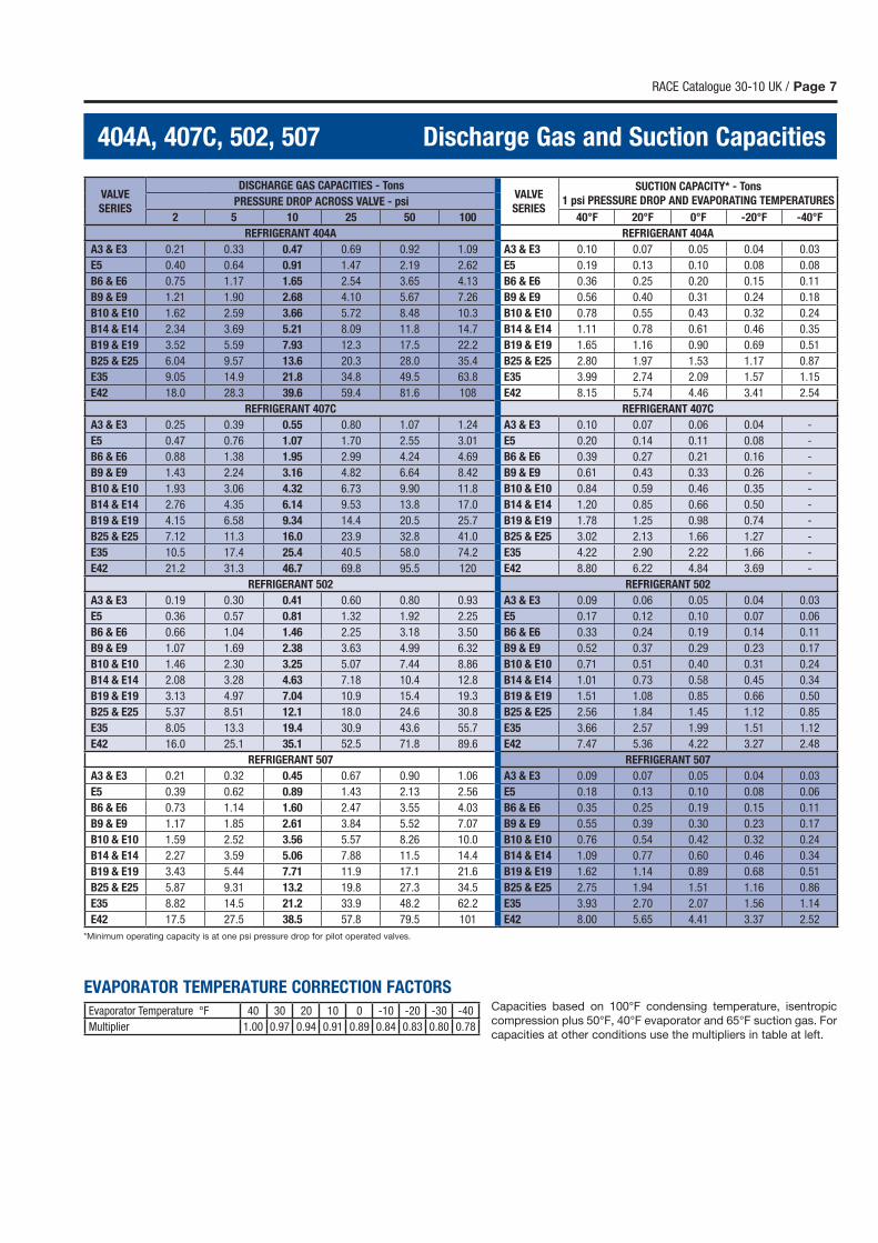
404A, 407C, 502, 507 Discharge Gas and Suction Capacities
Capacities based on 100°F condensing temperature, isentropic
compression plus 50°F, 40°F evaporator and 65°F suction gas. For
capacities at other conditions use the multipliers in table at left.
EVAPORATOR TEMPERATURE CORRECTION FACTORS
*Minimum operating capacity is at one psi pressure drop for pilot operated valves.
VALVE
SERIES
DISCHARGE GAS CAPACITIES - TonsVALVE
SERIES
SUCTION CAPACITY* - Tons
1 psi PRESSURE DROP AND EVAPORATING TEMPERATURESPRESSURE DROP ACROSS VALVE - psi
2 5 10 25 50 100 40°F 20°F 0°F -20°F -40°F
REFRIGERANT 404A REFRIGERANT 404A
A3 & E3 0.21 0.33 0.47 0.69 0.92 1.09 A3 & E3 0.10 0.07 0.05 0.04 0.03
E5 0.40 0.64 0.91 1.47 2.19 2.62 E5 0.19 0.13 0.10 0.08 0.08
B6 & E6 0.75 1.17 1.65 2.54 3.65 4.13 B6 & E6 0.36 0.25 0.20 0.15 0.11
B9 & E9 1.21 1.90 2.68 4.10 5.67 7.26 B9 & E9 0.56 0.40 0.31 0.24 0.18
B10 & E10 1.62 2.59 3.66 5.72 8.48 10.3 B10 & E10 0.78 0.55 0.43 0.32 0.24
B14 & E14 2.34 3.69 5.21 8.09 11.8 14.7 B14 & E14 1.11 0.78 0.61 0.46 0.35
B19 & E19 3.52 5.59 7.93 12.3 17.5 22.2 B19 & E19 1.65 1.16 0.90 0.69 0.51
B25 & E25 6.04 9.57 13.6 20.3 28.0 35.4 B25 & E25 2.80 1.97 1.53 1.17 0.87
E35 9.05 14.9 21.8 34.8 49.5 63.8 E35 3.99 2.74 2.09 1.57 1.15
E42 18.0 28.3 39.6 59.4 81.6 108 E42 8.15 5.74 4.46 3.41 2.54
REFRIGERANT 407C REFRIGERANT 407C
A3 & E3 0.25 0.39 0.55 0.80 1.07 1.24 A3 & E3 0.10 0.07 0.06 0.04 -
E5 0.47 0.76 1.07 1.70 2.55 3.01 E5 0.20 0.14 0.11 0.08 -
B6 & E6 0.88 1.38 1.95 2.99 4.24 4.69 B6 & E6 0.39 0.27 0.21 0.16 -
B9 & E9 1.43 2.24 3.16 4.82 6.64 8.42 B9 & E9 0.61 0.43 0.33 0.26 -
B10 & E10 1.93 3.06 4.32 6.73 9.90 11.8 B10 & E10 0.84 0.59 0.46 0.35 -
B14 & E14 2.76 4.35 6.14 9.53 13.8 17.0 B14 & E14 1.20 0.85 0.66 0.50 -
B19 & E19 4.15 6.58 9.34 14.4 20.5 25.7 B19 & E19 1.78 1.25 0.98 0.74 -
B25 & E25 7.12 11.3 16.0 23.9 32.8 41.0 B25 & E25 3.02 2.13 1.66 1.27 -
E35 10.5 17.4 25.4 40.5 58.0 74.2 E35 4.22 2.90 2.22 1.66 -
E42 21.2 31.3 46.7 69.8 95.5 120 E42 8.80 6.22 4.84 3.69 -
REFRIGERANT 502 REFRIGERANT 502
A3 & E3 0.19 0.30 0.41 0.60 0.80 0.93 A3 & E3 0.09 0.06 0.05 0.04 0.03
E5 0.36 0.57 0.81 1.32 1.92 2.25 E5 0.17 0.12 0.10 0.07 0.06
B6 & E6 0.66 1.04 1.46 2.25 3.18 3.50 B6 & E6 0.33 0.24 0.19 0.14 0.11
B9 & E9 1.07 1.69 2.38 3.63 4.99 6.32 B9 & E9 0.52 0.37 0.29 0.23 0.17
B10 & E10 1.46 2.30 3.25 5.07 7.44 8.86 B10 & E10 0.71 0.51 0.40 0.31 0.24
B14 & E14 2.08 3.28 4.63 7.18 10.4 12.8 B14 & E14 1.01 0.73 0.58 0.45 0.34
B19 & E19 3.13 4.97 7.04 10.9 15.4 19.3 B19 & E19 1.51 1.08 0.85 0.66 0.50
B25 & E25 5.37 8.51 12.1 18.0 24.6 30.8 B25 & E25 2.56 1.84 1.45 1.12 0.85
E35 8.05 13.3 19.4 30.9 43.6 55.7 E35 3.66 2.57 1.99 1.51 1.12
E42 16.0 25.1 35.1 52.5 71.8 89.6 E42 7.47 5.36 4.22 3.27 2.48
REFRIGERANT 507 REFRIGERANT 507
A3 & E3 0.21 0.32 0.45 0.67 0.90 1.06 A3 & E3 0.09 0.07 0.05 0.04 0.03
E5 0.39 0.62 0.89 1.43 2.13 2.56 E5 0.18 0.13 0.10 0.08 0.06
B6 & E6 0.73 1.14 1.60 2.47 3.55 4.03 B6 & E6 0.35 0.25 0.19 0.15 0.11
B9 & E9 1.17 1.85 2.61 3.84 5.52 7.07 B9 & E9 0.55 0.39 0.30 0.23 0.17
B10 & E10 1.59 2.52 3.56 5.57 8.26 10.0 B10 & E10 0.76 0.54 0.42 0.32 0.24
B14 & E14 2.27 3.59 5.06 7.88 11.5 14.4 B14 & E14 1.09 0.77 0.60 0.46 0.34
B19 & E19 3.43 5.44 7.71 11.9 17.1 21.6 B19 & E19 1.62 1.14 0.89 0.68 0.51
B25 & E25 5.87 9.31 13.2 19.8 27.3 34.5 B25 & E25 2.75 1.94 1.51 1.16 0.86
E35 8.82 14.5 21.2 33.9 48.2 62.2 E35 3.93 2.70 2.07 1.56 1.14
E42 17.5 27.5 38.5 57.8 79.5 101 E42 8.00 5.65 4.41 3.37 2.52
Evaporator Temperature °F 40 30 20 10 0 -10 -20 -30 -40
Multiplier 1.00 0.97 0.94 0.91 0.89 0.84 0.83 0.80 0.78
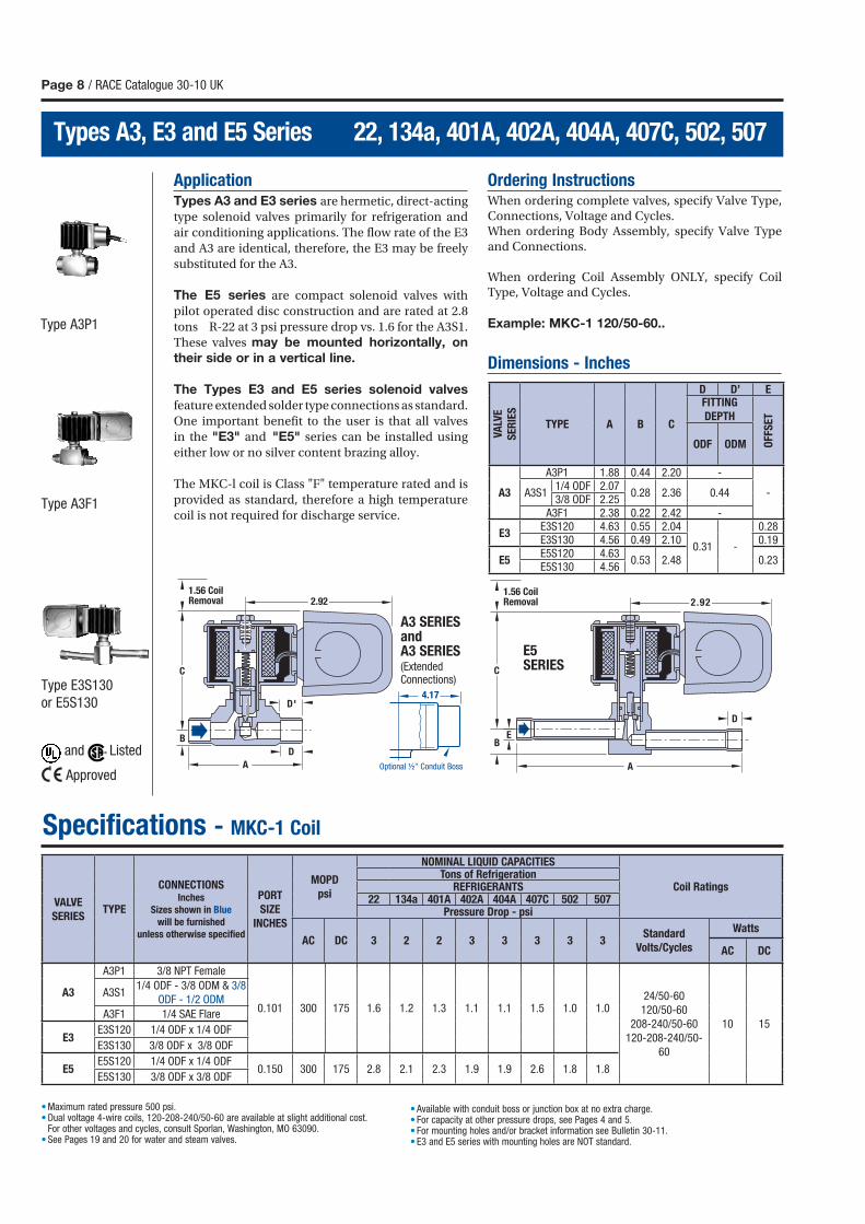
ApplicationTypes A3 and E3 series are hermetic, direct-acting
type solenoid valves primarily for refrigeration and
air conditioning applications. The flow rate of the E3
and A3 are identical, therefore, the E3 may be freely
substituted for the A3.
The E5 series are compact solenoid valves with
pilot operated disc construction and are rated at 2.8
tons R-22 at 3 psi pressure drop vs. 1.6 for the A3S1.
These valves may be mounted horizontally, on
their side or in a vertical line.
The Types E3 and E5 series solenoid valves
feature extended solder type connections as standard.
One important benefit to the user is that all valves
in the "E3" and "E5" series can be installed using
either low or no silver content brazing alloy.
The MKC-l coil is Class "F" temperature rated and is
provided as standard, therefore a high temperature
coil is not required for discharge service.
Ordering InstructionsWhen ordering complete valves, specify Valve Type, Connections, Voltage and Cycles.When ordering Body Assembly, specify Valve Type and Connections.
When ordering Coil Assembly ONLY, specify Coil Type, Voltage and Cycles.
Example: MKC-1 120/50-60..
Dimensions - Inches
Page 8 / RACE Catalogue 30-10 UK
Types A3, E3 and E5 Series 22, 134a, 401A, 402A, 404A, 407C, 502, 507
Specifications - MKC-1 Coil
C
D
EB
1.56 CoilRemoval 2.92
A
Type A3F1
Type E3S130
or E5S130
Type A3P1
• Maximum rated pressure 500 psi.• Dual voltage 4-wire coils, 120-208-240/50-60 are available at slight additional cost. For other voltages and cycles, consult Sporlan, Washington, MO 63090. • See Pages 19 and 20 for water and steam valves.
• Available with conduit boss or junction box at no extra charge.• For capacity at other pressure drops, see Pages 4 and 5.• For mounting holes and/or bracket information see Bulletin 30-11.• E3 and E5 series with mounting holes are NOT standard.
1.56 CoilRemoval 2.92
A
D'
D
C
B
4.17
Optional ½" Conduit Boss
A3 SERIES andA3 SERIES (Extended Connections)
E5 SERIES
and Listed
Approved
VA
LVE
SE
RIE
S
TYPE A B C
D D’ EFITTING
DEPTH
OFF
SE
T
ODF ODM
A3
A3P1 1.88 0.44 2.20 -
-A3S11/4 ODF 2.07
0.28 2.36 0.443/8 ODF 2.25
A3F1 2.38 0.22 2.42 -
E3E3S120 4.63 0.55 2.04
0.31 -
0.28E3S130 4.56 0.49 2.10 0.19
E5E5S120 4.63
0.53 2.48 0.23E5S130 4.56
VALVE
SERIESTYPE
CONNECTIONS Inches
Sizes shown in Blue
will be furnished
unless otherwise specifi ed
PORT
SIZE
INCHES
MOPD
psi
NOMINAL LIQUID CAPACITIES
Coil RatingsTons of Refrigeration
REFRIGERANTS22 134a 401A 402A 404A 407C 502 507
Pressure Drop - psi
AC DC 3 2 2 3 3 3 3 3Standard
Volts/Cycles
Watts
AC DC
A3
A3P1 3/8 NPT Female
0.101 300 175 1.6 1.2 1.3 1.1 1.1 1.5 1.0 1.024/50-60
120/50-60
208-240/50-60
120-208-240/50-
60
10 15
A3S11/4 ODF - 3/8 ODM & 3/8
ODF - 1/2 ODM
A3F1 1/4 SAE Flare
E3E3S120 1/4 ODF x 1/4 ODF
E3S130 3/8 ODF x 3/8 ODF
E5E5S120 1/4 ODF x 1/4 ODF
0.150 300 175 2.8 2.1 2.3 1.9 1.9 2.6 1.8 1.8E5S130 3/8 ODF x 3/8 ODF
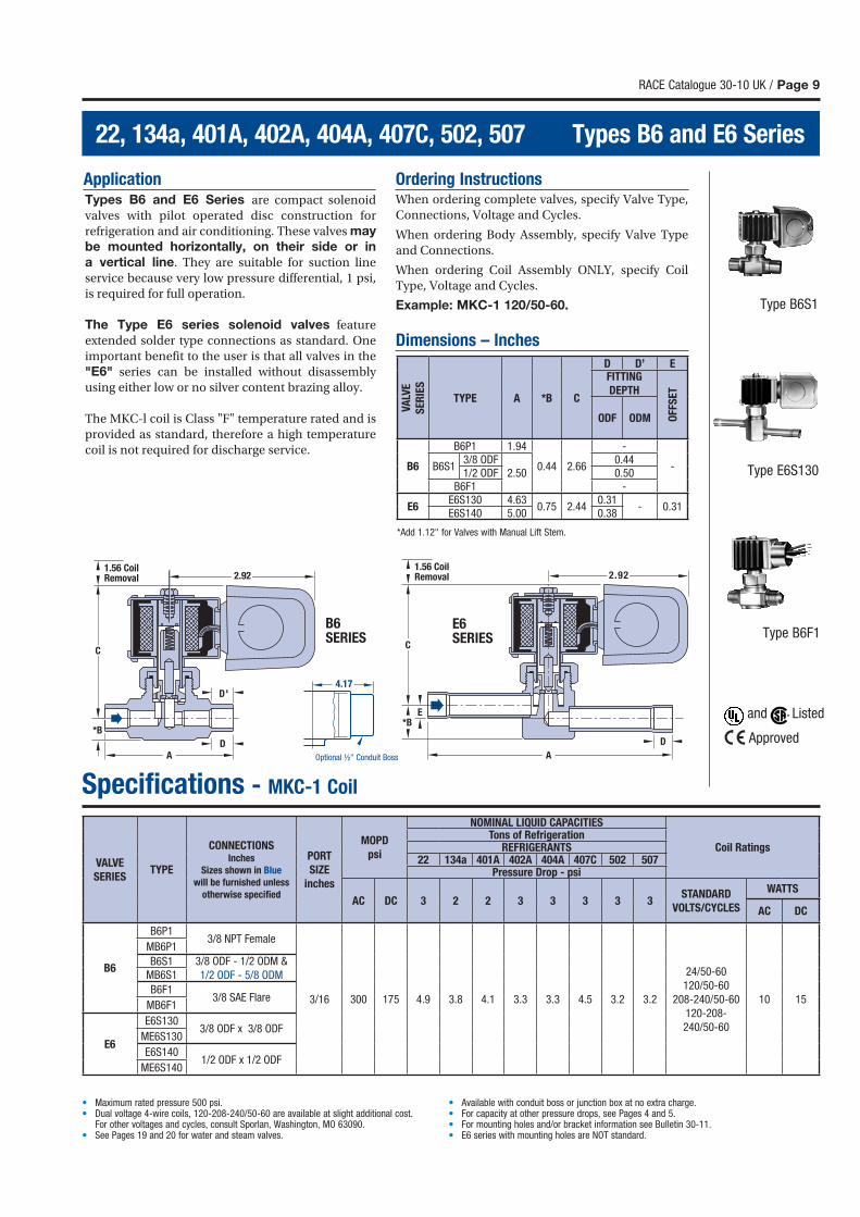
ApplicationTypes B6 and E6 Series are compact solenoid
valves with pilot operated disc construction for
refrigeration and air conditioning. These valves may
be mounted horizontally, on their side or in
a vertical line. They are suitable for suction line
service because very low pressure differential, 1 psi,
is required for full operation.
The Type E6 series solenoid valves feature
extended solder type connections as standard. One
important benefit to the user is that all valves in the
"E6" series can be installed without disassembly
using either low or no silver content brazing alloy.
The MKC-l coil is Class "F" temperature rated and is
provided as standard, therefore a high temperature
coil is not required for discharge service.
Ordering InstructionsWhen ordering complete valves, specify Valve Type,
Connections, Voltage and Cycles.
When ordering Body Assembly, specify Valve Type
and Connections.
When ordering Coil Assembly ONLY, specify Coil
Type, Voltage and Cycles.
Example: MKC-1 120/50-60.
Dimensions – Inches
RACE Catalogue 30-10 UK / Page 9
22, 134a, 401A, 402A, 404A, 407C, 502, 507 Types B6 and E6 Series
Specifications - MKC-1 Coil
1.56 CoilRemoval 2.92
A
D'
D
C
*B
Type B6S1
Type E6S130
Type B6F1
*Add 1.12" for Valves with Manual Lift Stem.
C
D
E*B
1.56 CoilRemoval 2.92
A
• Maximum rated pressure 500 psi.• Dual voltage 4-wire coils, 120-208-240/50-60 are available at slight additional cost. For other voltages and cycles, consult Sporlan, Washington, MO 63090. • See Pages 19 and 20 for water and steam valves.
• Available with conduit boss or junction box at no extra charge.• For capacity at other pressure drops, see Pages 4 and 5.• For mounting holes and/or bracket information see Bulletin 30-11.• E6 series with mounting holes are NOT standard.
4.17
Optional ½" Conduit Boss
B6 SERIES
E6 SERIES
VA
LVE
SE
RIE
S
TYPE A *B C
D D’ EFITTING
DEPTH
OFF
SE
T
ODF ODM
B6
B6P1 1.94
0.44 2.66
-
-B6S13/8 ODF
2.500.44
1/2 ODF 0.50B6F1 -
E6E6S130 4.63
0.75 2.440.31
- 0.31E6S140 5.00 0.38
VALVE
SERIESTYPE
CONNECTIONSInches
Sizes shown in Blue
will be furnished unless
otherwise specifi ed
PORT
SIZE
inches
MOPD
psi
NOMINAL LIQUID CAPACITIES
Coil RatingsTons of Refrigeration
REFRIGERANTS22 134a 401A 402A 404A 407C 502 507
Pressure Drop - psi
AC DC 3 2 2 3 3 3 3 3STANDARD
VOLTS/CYCLES
WATTS
AC DC
B6
B6P13/8 NPT Female
3/16 300 175 4.9 3.8 4.1 3.3 3.3 4.5 3.2 3.2
24/50-60
120/50-60
208-240/50-60
120-208-
240/50-60
10 15
MB6P1
B6S1 3/8 ODF - 1/2 ODM &
1/2 ODF - 5/8 ODMMB6S1
B6F13/8 SAE Flare
MB6F1
E6
E6S1303/8 ODF x 3/8 ODF
ME6S130
E6S1401/2 ODF x 1/2 ODF
ME6S140
and Listed
Approved
Page 10 / RACE Catalogue 30-10 UK
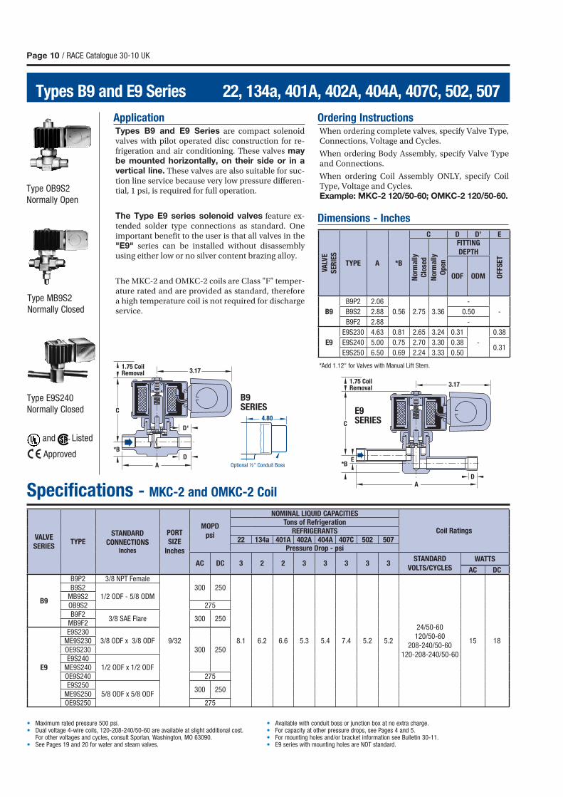
Types B9 and E9 Series 22, 134a, 401A, 402A, 404A, 407C, 502, 507
Specifications - MKC-2 and OMKC-2 Coil
Type MB9S2
Normally Closed
Type E9S240
Normally Closed
Type OB9S2
Normally Open
1.75 CoilRemoval
3.17
AD
*BE
C
E9 SERIES
1.75 CoilRemoval 3.17
A
D*B
D'
C4.80
Optional ½" Conduit Boss
B9 SERIES
ApplicationTypes B9 and E9 Series are compact solenoid valves with pilot operated disc construction for re-frigeration and air conditioning. These valves may be mounted horizontally, on their side or in a vertical line. These valves are also suitable for suc-tion line service because very low pressure differen-tial, 1 psi, is required for full operation.
The Type E9 series solenoid valves feature ex-tended solder type connections as standard. One important benefit to the user is that all valves in the "E9" series can be installed without disassembly using either low or no silver content brazing alloy.
The MKC-2 and OMKC-2 coils are Class "F" temper-ature rated and are provided as standard, therefore a high temperature coil is not required for discharge service.
Ordering InstructionsWhen ordering complete valves, specify Valve Type, Connections, Voltage and Cycles.
When ordering Body Assembly, specify Valve Type and Connections.
When ordering Coil Assembly ONLY, specify Coil Type, Voltage and Cycles.Example: MKC-2 120/50-60; OMKC-2 120/50-60.
Dimensions - Inches
*Add 1.12" for Valves with Manual Lift Stem.
VA
LVE
SE
RIE
S
TYPE A *B
C D D’ E
No
rma
lly
Clo
sed
No
rma
lly
Op
en
FITTING
DEPTH
OFF
SE
T
ODF ODM
B9
B9P2 2.06
0.56 2.75 3.36
-
-B9S2 2.88 0.50
B9F2 2.88 -
E9
E9S230 4.63 0.81 2.65 3.24 0.31
-
0.38
E9S240 5.00 0.75 2.70 3.30 0.380.31
E9S250 6.50 0.69 2.24 3.33 0.50
• Maximum rated pressure 500 psi.• Dual voltage 4-wire coils, 120-208-240/50-60 are available at slight additional cost. For other voltages and cycles, consult Sporlan, Washington, MO 63090. • See Pages 19 and 20 for water and steam valves.
• Available with conduit boss or junction box at no extra charge.• For capacity at other pressure drops, see Pages 4 and 5.• For mounting holes and/or bracket information see Bulletin 30-11.• E9 series with mounting holes are NOT standard.
VALVE
SERIESTYPE
STANDARD
CONNECTIONSInches
PORT
SIZE
Inches
MOPD
psi
NOMINAL LIQUID CAPACITIES
Coil RatingsTons of Refrigeration
REFRIGERANTS22 134a 401A 402A 404A 407C 502 507
Pressure Drop - psi
AC DC 3 2 2 3 3 3 3 3STANDARD
VOLTS/CYCLES WATTS
AC DC
B9
B9P2 3/8 NPT Female
9/32
300 250
8.1 6.2 6.6 5.3 5.4 7.4 5.2 5.2
24/50-60
120/50-60
208-240/50-60
120-208-240/50-60
15 18
B9S21/2 ODF - 5/8 ODMMB9S2
OB9S2 275B9F2
3/8 SAE Flare 300 250MB9F2
E9
E9S2303/8 ODF x 3/8 ODF
300 250ME9S230OE9S230E9S240
1/2 ODF x 1/2 ODFME9S240OE9S240 275E9S250
5/8 ODF x 5/8 ODF300 250
ME9S250OE9S250 275
and Listed
Approved
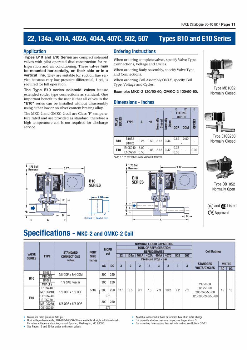
ApplicationTypes B10 and E10 Series are compact solenoid
valves with pilot operated disc construction for re-
frigeration and air conditioning. These valves may
be mounted horizontally, on their side or in a
vertical line. They are suitable for suction line ser-
vice because very low pressure differential, 1 psi, is
required for full operation.
The Type E10 series solenoid valves feature
extended solder type connections as standard. One
important benefit to the user is that all valves in the
"E10" series can be installed without disassembly
using either low or no silver content brazing alloy.
The MKC-2 and OMKC-2 coil are Class "F" tempera-
ture rated and are provided as standard, therefore a
high temperature coil is not required for discharge
service.
Ordering Instructions
When ordering complete valves, specify Valve Type,
Connections, Voltage and Cycles.
When ordering Body Assembly, specify Valve Type
and Connections.
When ordering Coil Assembly ONLY, specify Coil
Type, Voltage and Cycles.
Example: MKC-2 120/50-60; OMKC-2 120/50-60.
Dimensions - Inches
RACE Catalogue 30-10 UK / Page 11
22, 134a, 401A, 402A, 404A, 407C, 502, 507 Types B10 and E10 Series
1.75 CoilRemoval 3.17
A
D
C
*BE
1.75 CoilRemoval 3.17
A
D
D'
C
*B
Type MB10S2
Normally Closed
Type E10S250
Normally Closed
Type OB10S2
Normally Open
E10 SERIESB10
SERIES
4.80
Optional ½" Conduit Boss
Specifications - MKC-2 and OMKC-2 Coil
*Add 1.12" for Valves with Manual Lift Stem.
VA
LVE
SE
RIE
STYPE A *B
C D D’ E
No
rma
lly
Clo
sed
No
rma
lly
Op
en
FITTING
DEPTH
OFF
SE
T
ODF ODM
B10B10S2
3.25 0.59 3.15 3.440.62 0.50
-B10F2 -
E10E10S240 5.00
0.86 3.13 3.420.38
- 0.39E10S250 6.50 0.50
• Maximum rated pressure 500 psi.• Dual voltage 4-wire coils, 120-208-240/50-60 are available at slight additional cost. For other voltages and cycles, consult Sporlan, Washington, MO 63090. • See Pages 19 and 20 for water and steam valves.
• Available with conduit boss or junction box at no extra charge.• For capacity at other pressure drops, see Pages 4 and 5.• For mounting holes and/or bracket information see Bulletin 30-11.
VALVE
SERIESTYPE
STANDARD
CONNECTIONSInches
PORT
SIZE
Inches
MOPD
psi
NOMINAL LIQUID CAPACITIES
Coil RatingsTONS OF REFRIGERATIÓN
REFRIGERANTS22 134a 401A 402A 404A 407C 502 507
Pressure Drop - psi
AC DC 3 2 2 3 3 3 3 3STANDARD
VOLTS/CYCLES WATTS
AC DC
B10
B10S25/8 ODF x 3/4 ODM
5/16
300 250
11.1 8.5 9.1 7.3 7.3 10.2 7.2 7.2
24/50-60
120/50-60
208-240/50-60
120-208-240/50-60
15 18
MB10S2B10F2
1/2 SAE Roscar 300 250MB10F2
E10
E10S2401/2 ODF x 1/2 ODF
300 250ME10S240OE10S240 275E10S250
5/8 ODF x 5/8 ODF300 250
ME10S250OE10S250 275
and Listed
Approved

Page 12 / RACE Catalogue 30-10 UK
Types B14 and E14 Series 22, 134a, 401A, 402A, 404A, 407C, 502, 507
ApplicationTypes B14 and E14 Series are compact solenoid
valves with pilot operated disc construction for
refrigeration and air conditioning. These valves may
be mounted horizontally, on their side or in a vertical
line. These valves are also suitable for suction line
service because very low pressure differential, 1 psi,
is required for full operation.
The Type E14 series solenoid valves feature
extended solder type connections as standard. One
important benefit to the user is that all valves in the
"E14" series can be installed without disassembly
using either low or no silver content brazing alloy.
The MKC-2 and OMKC-2 coils are Class "F"
temperature rated and are provided as standard,
therefore a high temperature coil is not required for
discharge service.
Ordering InstructionsWhen ordering complete valves, specify Valve Type,
Connections, Voltage and Cycles.
When ordering Body Assembly, specify Valve Type
and Connections.
When ordering Coil Assembly ONLY, specify Coil
Type, Voltage and Cycles.
Example: MKC-2 120/50-60; OMKC-2 120/50-60.
Dimensions - Inches*
Specifications - MKC-2 and OMKC-2 Coil
Type MB14S2
Normally Closed
Type OB14S2
Normally Open
Type E14S250
Normally Closed
1.75 CoilRemoval 3.17
AD
*B
C
D'
1.75 CoilRemoval 3.17
A
D
*B
C
E14 SERIES
B14 SERIES
4.80
Optional 1/2" Conduit Boss
*Add 1.12" for Valves with Manual Lift Stem.
VA
LVE
SE
RIE
S
TYPE A *B
C D D’
No
rma
lly
Clo
sed
No
rma
lly
Op
en
FITTING
DEPTH
ODF ODM
B14B14P2 2.41
0.56 3.28 3.62-
B14S2 3.00 0.62 0.50
E14 E14S250 6.88 0.47 3.25 3.51 0.50 -
• Maximum rated pressure 500 psi.• Dual voltage 4-wire coils, 120-208-240/50-60 are available at slight additional cost. For other voltages and cycles, consult Sporlan, Washington, MO 63090.
• See Pages 19 and 20 for water and steam valves.• Available with conduit boss or junction box at no extra charge.• For capacity at other pressure drops, see Pages 4 and 5.• For mounting holes and/or bracket information see Bulletin 30-11.
VALVE
SERIESTYPE
STANDARD
CONNECTIONSInches
PORT
SIZE
Inches
MOPD
psi
NOMINAL LIQUID CAPACITIES
Coil RatingsTONS OF REFRIGERATION
REFRIGERANTS22 134a 401A 402A 404A 407C 502 507
Pressure Drop - psi
AC DC 3 2 2 3 3 3 3 3STANDARD
VOLTS/CYCLES WATTS
AC DC
B14
B14P2 1/2 NPT Female
7/16
300 250
15.8 12.0 12.9 10.4 10.4 14.5 10.2 10.2
24/50-60
120/50-60
208-240/50-60
120-208-240/50-60
15 18
B14S25/8 ODF - 7/8 ODM
300 250MB14S2OB14S2 275
E14
E14S2505/8 ODF x 5/8 ODF
300 250ME14S250OE14S250 275E14S270
7/8 ODF x 7/8 ODF 300 250ME14S270
and Listed
Approved
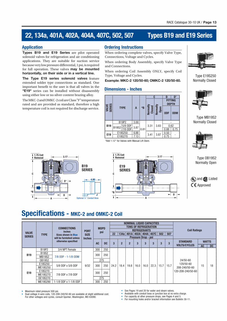
ApplicationTypes B19 and E19 Series are pilot operated
solenoid valves for refrigeration and air conditioning
applications. They are suitable for suction service
because very low pressure differential, 1 psi, is required
for full operation. These valves may be mounted
horizontally, on their side or in a vertical line.
The Type E19 series solenoid valves feature
extended solder type connections as standard. One
important benefit to the user is that all valves in the
"E19" series can be installed without disassembly
using either low or no silver content brazing alloy.
The MKC-2 and OMKC-2 coil are Class "F" temperature
rated and are provided as standard, therefore a high
temperature coil is not required for discharge service.
Ordering InstructionsWhen ordering complete valves, specify Valve Type,
Connections, Voltage and Cycles.
When ordering Body Assembly, specify Valve Type
and Connections.
When ordering Coil Assembly ONLY, specify Coil
Type, Voltage and Cycles.
Example: MKC-2 120/50-60; OMKC-2 120/50-60.
Dimensions - Inches
RACE Catalogue 30-10 UK / Page 13
22, 134a, 401A, 402A, 404A, 407C, 502, 507 Types B19 and E19 Series
1.75 CoilRemoval 3.17
D
D'
*B
C
A
1.75 CoilRemoval 3.17
D*B
C
A
Specifications - MKC-2 and OMKC-2 Coil
Type E19S250
Normally Closed
Type MB19S2
Normally Closed
Type OB19S2
Normally OpenE19 SERIES
B19 SERIES
4.80
Optional ½" Conduit Boss
*Add 1.12" for Valves with Manual Lift Stem.
VA
LVE
SE
RIE
STYPE A *B
C D D’
No
rma
lly
Clo
sed
No
rma
lly
Op
en
FITTING
DEPTH
ODF ODM
B19B19P2 3.00
0.813.31 3.83
-
B19S25/8 ODF
3.870.62
7/8 ODF 0.88 0.75
E19E19S250 6.88
3.41 3.870.50
-E19S270 7.13 0.75
• Maximum rated pressure 500 psi.• Dual voltage 4-wire coils, 120-208-240/50-60 are available at slight additional cost. For other voltages and cycles, consult Sporlan, Washington, MO 63090.
• See Pages 19 and 20 for water and steam valves.• Available with conduit boss or junction box at no extra charge.• For capacity at other pressure drops, see Pages 4 and 5.• For mounting holes and/or bracket information see Bulletin 30-11.
VALVE
SERIESTYPE
CONNECTIONSInches
Sizes shown in Blue
will be furnished unless
otherwise specifi ed
PORT
SIZE
Inches
MOPD
psi
NOMINAL LIQUID CAPACITIES
Coil RatingsTONS OF REFRIGERATION
REFRIGERANTS22 134a 401A 402A 404A 407C 502 507
Pressure Drop - psi
AC DC 3 2 2 3 3 3 3 3STANDARD
VOLTS/CYCLES WATTS
AC DC
B19
B19P2 3/4 NPT Female
9/32
300 250
24.2 18.4 19.8 16.0 16.0 22.3 15.7 15.7
24/50-60
120/50-60
208-240/50-60
120-208-240/50-60
15 18
B19S27/8 ODF - 1-1/8 ODM
300 250MB19S2OB19S2 275
E19
E19S2505/8 ODF x 5/8 ODF 300 250
ME19S250E19S270
7/8 ODF x 7/8 ODF300 250
ME19S270OE19S270 275ME19S290 1-1/8 ODF x 1-1/8 ODF 300 250
and Listed
Approved
Page 14 / RACE Catalogue 30-10 UK
Types B25 and E25 Series 22, 134a, 401A, 402A, 404A, 407C, 502, 507
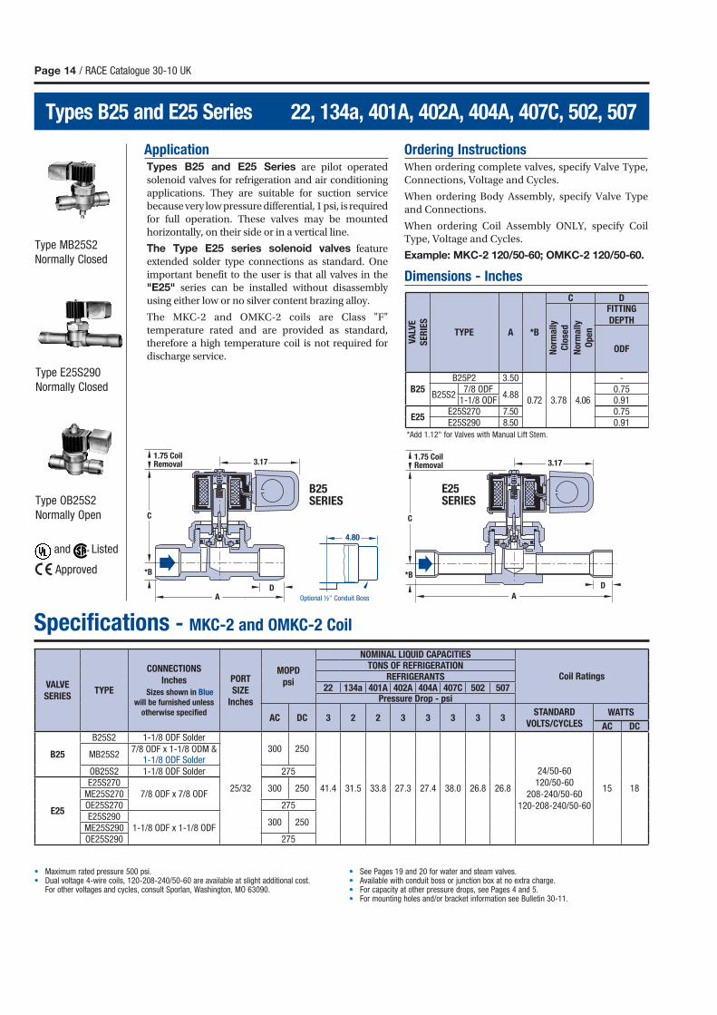
ApplicationTypes B25 and E25 Series are pilot operated
solenoid valves for refrigeration and air conditioning
applications. They are suitable for suction service
because very low pressure differential, 1 psi, is required
for full operation. These valves may be mounted
horizontally, on their side or in a vertical line.
The Type E25 series solenoid valves feature
extended solder type connections as standard. One
important benefit to the user is that all valves in the
"E25" series can be installed without disassembly
using either low or no silver content brazing alloy.
The MKC-2 and OMKC-2 coils are Class "F"
temperature rated and are provided as standard,
therefore a high temperature coil is not required for
discharge service.
Ordering InstructionsWhen ordering complete valves, specify Valve Type,
Connections, Voltage and Cycles.
When ordering Body Assembly, specify Valve Type
and Connections.
When ordering Coil Assembly ONLY, specify Coil
Type, Voltage and Cycles.
Example: MKC-2 120/50-60; OMKC-2 120/50-60.
Dimensions - Inches
Specifications - MKC-2 and OMKC-2 Coil
Type E25S290
Normally Closed
Type OB25S2
Normally Open
Type MB25S2
Normally Closed
1.75 CoilRemoval 3.17
D
*B
C
A
1.75 CoilRemoval 3.17
D
*B
C
A
B25 SERIES
4.80
Optional ½" Conduit Boss
E25 SERIES
*Add 1.12" for Valves with Manual Lift Stem.
VA
LVE
SE
RIE
S
TYPE A *B
C D
No
rma
lly
Clo
sed
No
rma
lly
Op
en
FITTING
DEPTH
ODF
B25B25P2 3.50
0.72 3.78 4.06
-
B25S27/8 ODF
4.880.75
1-1/8 ODF 0.91
E25E25S270 7.50 0.75E25S290 8.50 0.91
• Maximum rated pressure 500 psi.• Dual voltage 4-wire coils, 120-208-240/50-60 are available at slight additional cost. For other voltages and cycles, consult Sporlan, Washington, MO 63090.
• See Pages 19 and 20 for water and steam valves.• Available with conduit boss or junction box at no extra charge.• For capacity at other pressure drops, see Pages 4 and 5.• For mounting holes and/or bracket information see Bulletin 30-11.
VALVE
SERIESTYPE
CONNECTIONS
Inches
Sizes shown in Blue
will be furnished unless
otherwise specifi ed
PORT
SIZE
Inches
MOPD
psi
NOMINAL LIQUID CAPACITIES
Coil RatingsTONS OF REFRIGERATION
REFRIGERANTS22 134a 401A 402A 404A 407C 502 507
Pressure Drop - psi
AC DC 3 2 2 3 3 3 3 3STANDARD
VOLTS/CYCLES WATTS
AC DC
B25
B25S2 1-1/8 ODF Solder
25/32
300 250
41.4 31.5 33.8 27.3 27.4 38.0 26.8 26.8
24/50-60
120/50-60
208-240/50-60
120-208-240/50-60
15 18
MB25S27/8 ODF x 1-1/8 ODM &
1-1/8 ODF SolderOB25S2 1-1/8 ODF Solder 275
E25
E25S2707/8 ODF x 7/8 ODF
300 250ME25S270OE25S270 275E25S290
1-1/8 ODF x 1-1/8 ODF300 250
ME25S290OE25S290 275
and Listed
Approved
RACE Catalogue 30-10 UK / Page 15
22, 134a, 401A, 402A, 404A, 407C, 502, 507 Types E35 Series
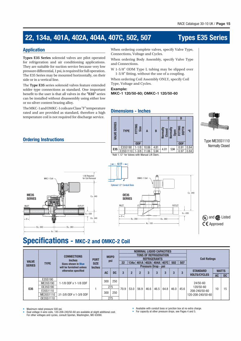
Application
Types E35 Series solenoid valves are pilot operated
for refrigeration and air conditioning applications.
They are suitable for suction service because very low
pressure differential, 1 psi, is required for full operation.
The E35 Series may be mounted horizontally, on their
side or in a vertical line.
The Type E35 series solenoid valves feature extended
solder type connections as standard. One important
benefit to the user is that all valves in the "E35" series
can be installed without disassembly using either low
or no silver content brazing alloy.
The MKC-1 and OMKC-1 coils are Class "F" temperature
rated and are provided as standard, therefore a high
temperature coil is not required for discharge service.
Ordering Instructions
When ordering complete valves, specify Valve Type,
Connections, Voltage and Cycles.
When ordering Body Assembly, specify Valve Type
and Connections.
W 1-5/8" ODM Type L tubing may be slipped over
1-3/8" fitting, without the use of a coupling.
When ordering Coil Assembly ONLY, specify Coil
Type, Voltage and Cycles.
Example:
MKC-1 120/50-60; OMKC-1 120/50-60
Dimensions - Inches
Specifications - MKC-2 and OMKC-2 Coil
Type ME35S1110
Normally Closed
OE35 SERIES
4.17
Optional 1/2" Conduit Boss
OMKC-1 Coil
INLET OUTLET
C± .040
E± .020
B± .060B± .060
A± .100
D
MKC-1 Coil
INLET OUTLET
C± .040
D± .040
E± .020
B± .060B± .060
A± .100
1.56 Requiredfor Coil Removal
D
ME35 SERIES
*Add 1.12" for Valves with Manual Lift Stem.
VA
LVE
SE
RIE
S
TYPE
FIT
TIN
G
Siz
e
A B
C D
*E
Norm
ally
Clo
sed
Norm
ally
Op
en
FITT
ING
DE
PT
H
ODF ODF
E35E35S190 1-1/8 10.06 4.81
4.81 5.940.91 0.84
E35S1110 1-3/8 11.06 5.94 0.97 0.84
• Maximum rated pressure 500 psi.• Dual voltage 4-wire coils, 120-208-240/50-60 are available at slight additional cost. For other voltages and cycles, consult Sporlan, Washington, MO 63090.
• Available with conduit boss or junction box at no extra charge.• For capacity at other pressure drops, see Pages 4 and 5.
VALVE
SERIESTYPE
CONNECTIONS
InchesSizes shown in Blue
will be furnished unless
otherwise specifi ed
PORT
SIZE
Inches
MOPD
psi
NOMINAL LIQUID CAPACITIES
Coil RatingsTONS OF REFRIGERATION
REFRIGERANTS22 134a 401A 402A 404A 407C 502 507
Pressure Drop - psi
AC DC 3 2 2 3 3 3 3 3STANDARD
VOLTS/CYCLES WATTS
AC DC
E35
E35S1901-1/8 ODF x 1-1/8 ODF
1
300 250
70.9 53.0 56.9 46.6 46.5 64.8 46.0 45.6
24/50-60
120/50-60
208-240/50-60
120-208-240/50-60
10 15
ME35S190OE35S190 275E35S1110
21-3/8 ODF x 1-3/8 ODF300 250
ME35S1110OE35S1110 275
and Listed
Approved
Page 16 / RACE Catalogue 30-10 UK
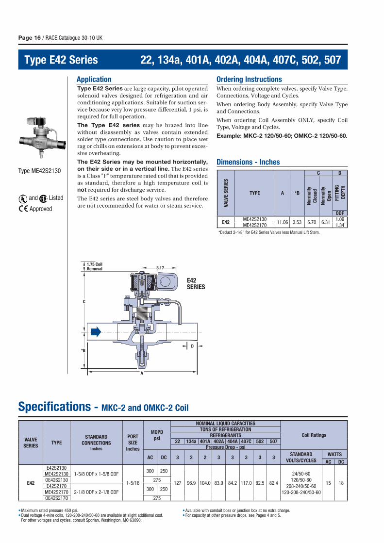
Type E42 Series 22, 134a, 401A, 402A, 404A, 407C, 502, 507
D
C
1.75 CoilRemoval 3.17
A
*B
ApplicationType E42 Series are large capacity, pilot operated
solenoid valves designed for refrigeration and air
conditioning applications. Suitable for suction ser-
vice because very low pressure differential, 1 psi, is
required for full operation.
The Type E42 series may be brazed into line
without disassembly as valves contain extended
solder type connections. Use caution to place wet
rag or chills on extensions at body to prevent exces-
sive overheating.
The E42 Series may be mounted horizontally,
on their side or in a vertical line. The E42 series
is a Class "F" temperature rated coil that is provided
as standard, therefore a high temperature coil is
not required for discharge service.
The E42 series are steel body valves and therefore
are not recommended for water or steam service.
Ordering InstructionsWhen ordering complete valves, specify Valve Type,
Connections, Voltage and Cycles.
When ordering Body Assembly, specify Valve Type
and Connections.
When ordering Coil Assembly ONLY, specify Coil
Type, Voltage and Cycles.
Example: MKC-2 120/50-60; OMKC-2 120/50-60.
Dimensions - InchesType ME42S2130
Specifications - MKC-2 and OMKC-2 Coil
E42 SERIES
*Deduct 2-1/8" for E42 Series Valves less Manual Lift Stem.
VA
LVE
SE
RIE
S
TYPE A *B
C D
No
rma
lly
Clo
sed
No
rma
lly
Op
en
FIT
TIN
G
DE
PT
H
ODF
E42ME42S2130
11.06 3.53 5.70 6.311.09
ME42S2170 1.34
• Maximum rated pressure 450 psi.• Dual voltage 4-wire coils, 120-208-240/50-60 are available at slight additional cost. For other voltages and cycles, consult Sporlan, Washington, MO 63090.
• Available with conduit boss or junction box at no extra charge.• For capacity at other pressure drops, see Pages 4 and 5.
VALVE
SERIESTYPE
STANDARD
CONNECTIONS Inches
PORT
SIZE
Inches
MOPD
psi
NOMINAL LIQUID CAPACITIES
Coil RatingsTONS OF REFRIGERATION
REFRIGERANTS22 134a 401A 402A 404A 407C 502 507
Pressure Drop - psi
AC DC 3 2 2 3 3 3 3 3STANDARD
VOLTS/CYCLES WATTS
AC DC
E42
E42S21301-5/8 ODF x 1-5/8 ODF
1-5/16
300 250
127 96.9 104.0 83.9 84.2 117.0 82.5 82.4
24/50-60
120/50-60
208-240/50-60
120-208-240/50-60
15 18
ME42S2130OE42S2130 275E42S2170
2-1/8 ODF x 2-1/8 ODF300 250
ME42S2170OE42S2170 275
and Listed
Approved
RACE Catalogue 30-10 UK / Page 17
22, 134a, 401A, 402A, 404A, 407C, 502, 507 Built-In Check Valve Series
Type CMB19S2
Type CE14S250
LIQUID
SUCTION
DISCHARGEFigure 2 Replaceable
Catch-All
See-All
Receiver
OLDRLiquidDifferentialValve
Liquid LineSolenoid Valve withCheck Valve Feature
Liquid LineSolenoid Valve
Check Valve
Check Valve
Evaporador
Check Valve
Evaporator
TEV
TEV
Distributor
Su
ctio
n H
ead
er
Def
rost
Hea
der
3-Way 10G711BDefrost Valve
2-Way Solenoid Defrost Valve
SORIT-, CDS-, SuctionThrottling Valves or Solenoid
Stop Valve for Defrost
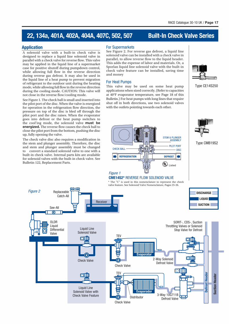
ApplicationA solenoid valve with a built-in check valve is designed to replace a liquid line solenoid valve in parallel with a check valve for reverse flow. This valve may be applied in the liquid line of a supermarket case for positive shutoff during pumpdown control, while allowing full flow in the reverse direction during reverse gas defrost. It may also be used in the liquid line of a heat pump to prevent migration of refrigerant to the outdoor unit during the heating mode, while allowing full flow in the reverse direction during the cooling mode. CAUTION: This valve will not close in the reverse flow/cooling mode.
See Figure 1. The check ball is small and inserted into the pilot port of the disc. When the valve is energized for operation in the refrigeration flow direction, the pressure on top of the disc is bled off through the pilot port and the disc raises. When the evaporator goes into defrost or the heat pump switches to the cool’ing mode, the solenoid valve must be energized. The reverse flow causes the check ball to close the pilot port from the bottom, pushing the disc up, fully opening the valve.
The check valve disc also requires a modification in the stem and plunger assembly. Therefore, the disc and stem and plunger assembly must be changed to convert a standard solenoid valve to one with a built-in check valve. Internal parts kits are available for solenoid valves with the built-in check valve. See Bulletin 122, Replacement Parts.
For SupermarketsSee Figure 2. For reverse gas defrost, a liquid line solenoid valve can be installed with a check valve in parallel, to allow reverse flow to the liquid header. This adds the expense of labor and materials. Or, a Sporlan liquid line solenoid valve with the built-in check valve feature can be installed, saving time and money
For Heat PumpsThis valve may be used on some heat pump
applications when sized correctly. (Refer to capacities
at 40°F evaporator temperature, see Page 18 of this
Bulletin.) For heat pumps with long lines that require
shut off in both directions, use two solenoid valves
with the outlets pointing towards each other.
Figure 1
CME14S2* REVERSE FLOW SOLENOID VALVE
Listed
REFRIGERATION
CHECK BALLPILOT PORT
DISC
DEFROST
STEM & PLUNGERASSEMBLY
* The "C" is used in this nomenclature to represent the check valve feature. See Solenoid Valve Nomenclature, Pages 25-26.
Page 18 / RACE Catalogue 30-10 UK
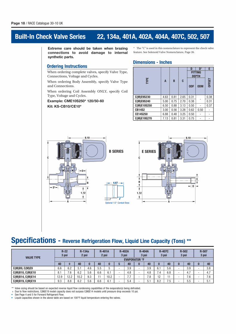
Built-In Check Valve Series 22, 134a, 401A, 402A, 404A, 407C, 502, 507
Extreme care should be taken when brazing
connections to avoid damage to internal
synthetic parts.
Ordering InstructionsWhen ordering complete valves, specify Valve Type,
Connections, Voltage and Cycles.
When ordering Body Assembly, specify Valve Type
and Connections.
When ordering Coil Assembly ONLY, specify Coil
Type, Voltage and Cycles.
Example: CME10S250* 120/50-60
Kit: KS-CB10/CE10*
* The "C" is used in this nomenclature to represent the check valve
feature. See Solenoid Valve Nomenclature, Page 26.
Dimensions - Inches
Specifications - Reverse Refrigeration Flow, Liquid Line Capacity (Tons) **
** Valve sizing should be based on expected reverse liquid flow condensing capabilities of the evaporator(s) being defrosted. + Due to flow restrictions, C(M)E19 model capacity does not surpass C(M)E14 models until pressure drop exceeds 10 psi.• See Page 4 and 5 for Forward Refrigerant Flow.• Liquid capacities shown in the above table are based on 100°F liquid temperature entering the valves.
8.10
A
D
D'
C
B
1.12
8.10
A
D
C
BE
1.12
B SERIES E SERIES
4.67
Optional 1/2" Conduit Boss
TY
PE
A B C
D D’ EFITTING
DEPTH
OFF
SE
T
ODF ODM
C(M)E9S230 4.63 0.81 2.65 0.31-
0.38
C(M)E9S240 5.00 0.75 2.70 0.38 0.31
C(M)E10S250 6.50 0.88 3.13 0.50 - 0.37
CB14S2 3.00 0.56 3.28 0.62 0.50 -
CE14S250 6.88 0.48 3.25 0.50 - -
C(M)E19S270 7.13 0.81 3.31 0.75 - -
VALVE TYPE
R-22
3 psi
R-134a
2 psi
R-401A
2 psi
R-402A
3 psi
R-404A
3 psi
R-407C
3 psi
R-502
3 psi
R-507
3 psi
EVAPORATOR °F
40 0 40 0 40 0 5 40 0 40 0 40 0 40 0 40
C(M)B9, C(M)E9 6.6 6.2 5.1 4.6 5.5 5 - 3.9 - 3.9 6.1 5.6 - 3.9 - 3.8
C(M)B10, C(M)E10 8.1 7.6 6.2 5.6 6.6 6.1 - 4.8 - 4.8 7.4 6.8 - 4.7 - 4.7
C(M)B14, C(M)E14 12.9 12.2 10.2 9.3 11 10.2 - 7.7 - 7.8 12 11 - 7.6 - 7.6
C(M)B19, C(M)E19 9.3 8.8 6.2 5.6 6.6 6.1 - 5.4 - 5.1 8.2 7.5 - 5.5 - 5.1
RACE Catalogue 30-10 UK / Page 19
for Air, Water, Steam and Light Oil Industrial Solenoid Valves
Specifications
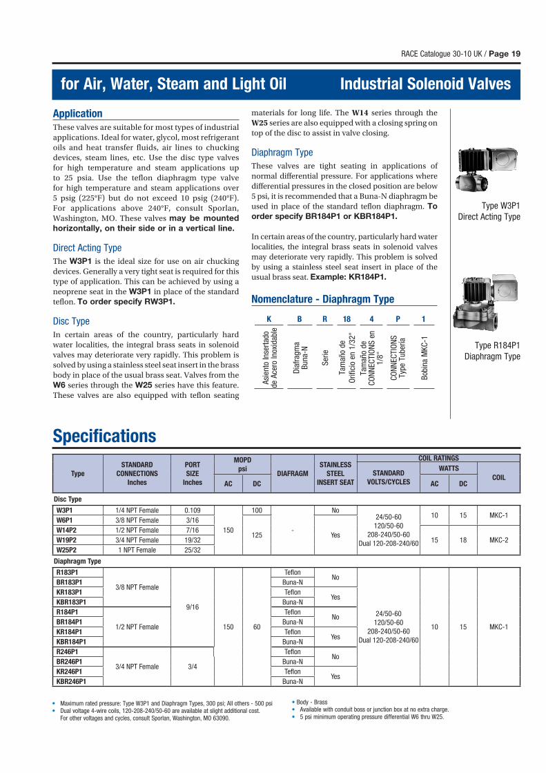
Type R184P1
Diaphragm Type
Type W3P1
Direct Acting Type
ApplicationThese valves are suitable for most types of industrial
applications. Ideal for water, glycol, most refrigerant
oils and heat transfer fluids, air lines to chucking
devices, steam lines, etc. Use the disc type valves
for high temperature and steam applications up
to 25 psia. Use the teflon diaphragm type valve
for high temperature and steam applications over
5 psig (225°F) but do not exceed 10 psig (240°F).
For applications above 240°F, consult Sporlan,
Washington, MO. These valves may be mounted
horizontally, on their side or in a vertical line.
Direct Acting Type
The W3P1 is the ideal size for use on air chucking
devices. Generally a very tight seat is required for this
type of application. This can be achieved by using a
neoprene seat in the W3P1 in place of the standard
teflon. To order specify RW3P1.
Disc Type
In certain areas of the country, particularly hard
water localities, the integral brass seats in solenoid
valves may deteriorate very rapidly. This problem is
solved by using a stainless steel seat insert in the brass
body in place of the usual brass seat. Valves from the
W6 series through the W25 series have this feature.
These valves are also equipped with teflon seating
materials for long life. The W14 series through the
W25 series are also equipped with a closing spring on
top of the disc to assist in valve closing.
Diaphragm Type
These valves are tight seating in applications of
normal differential pressure. For applications where
differential pressures in the closed position are below
5 psi, it is recommended that a Buna-N diaphragm be
used in place of the standard teflon diaphragm. To
order specify BR184P1 or KBR184P1.
In certain areas of the country, particularly hard water
localities, the integral brass seats in solenoid valves
may deteriorate very rapidly. This problem is solved
by using a stainless steel seat insert in place of the
usual brass seat. Example: KR184P1.
Nomenclature - Diaphragm Type
K B R 81 4 P 1
Asi
ento
Inse
rtad
o de
Ace
ro In
oxid
able
Dia
frag
ma
Bun
a-N
Ser
ie
Tam
año
de
Ori
ficio
en
1/3
2"
Tam
año
de
CO
NN
ECTI
ON
S e
n 1
/8"
CO
NN
ECTI
ON
S
Type
Tub
ería
Bob
ina
MK
C-1
Type
STANDARD
CONNECTIONS
Inches
PORT
SIZE
Inches
MOPD
psiDIAFRAGM
STAINLESS
STEEL
INSERT SEAT
COIL RATINGS
STANDARD
VOLTS/CYCLES
WATTS
COILAC DC AC DC
Disc Type
W3P1 1/4 NPT Female 0.109
150
100
-
No24/50-60
120/50-60
208-240/50-60
Dual 120-208-240/60
10 15 MKC-1W6P1 3/8 NPT Female 3/16
125 YesW14P2 1/2 NPT Female 7/16
15 18 MKC-2W19P2 3/4 NPT Female 19/32
W25P2 1 NPT Female 25/32
Diaphragm Type
R183P1
3/8 NPT Female
9/16
150 60
Tefl onNo
24/50-60
120/50-60
208-240/50-60
Dual 120-208-240/60
10 15 MKC-1
BR183P1 Buna-N
KR183P1 Tefl onYes
KBR183P1 Buna-N
R184P1
1/2 NPT Female
Tefl onNo
BR184P1 Buna-N
KR184P1 Tefl onYes
KBR184P1 Buna-N
R246P1
3/4 NPT Female 3/4
Tefl onNo
BR246P1 Buna-N
KR246P1 Tefl onYes
KBR246P1 Buna-N
• Maximum rated pressure: Type W3P1 and Diaphragm Types, 300 psi; All others - 500 psi• Dual voltage 4-wire coils, 120-208-240/50-60 are available at slight additional cost. For other voltages and cycles, consult Sporlan, Washington, MO 63090.
• Body - Brass• Available with conduit boss or junction box at no extra charge.• 5 psi minimum operating pressure differential W6 thru W25.
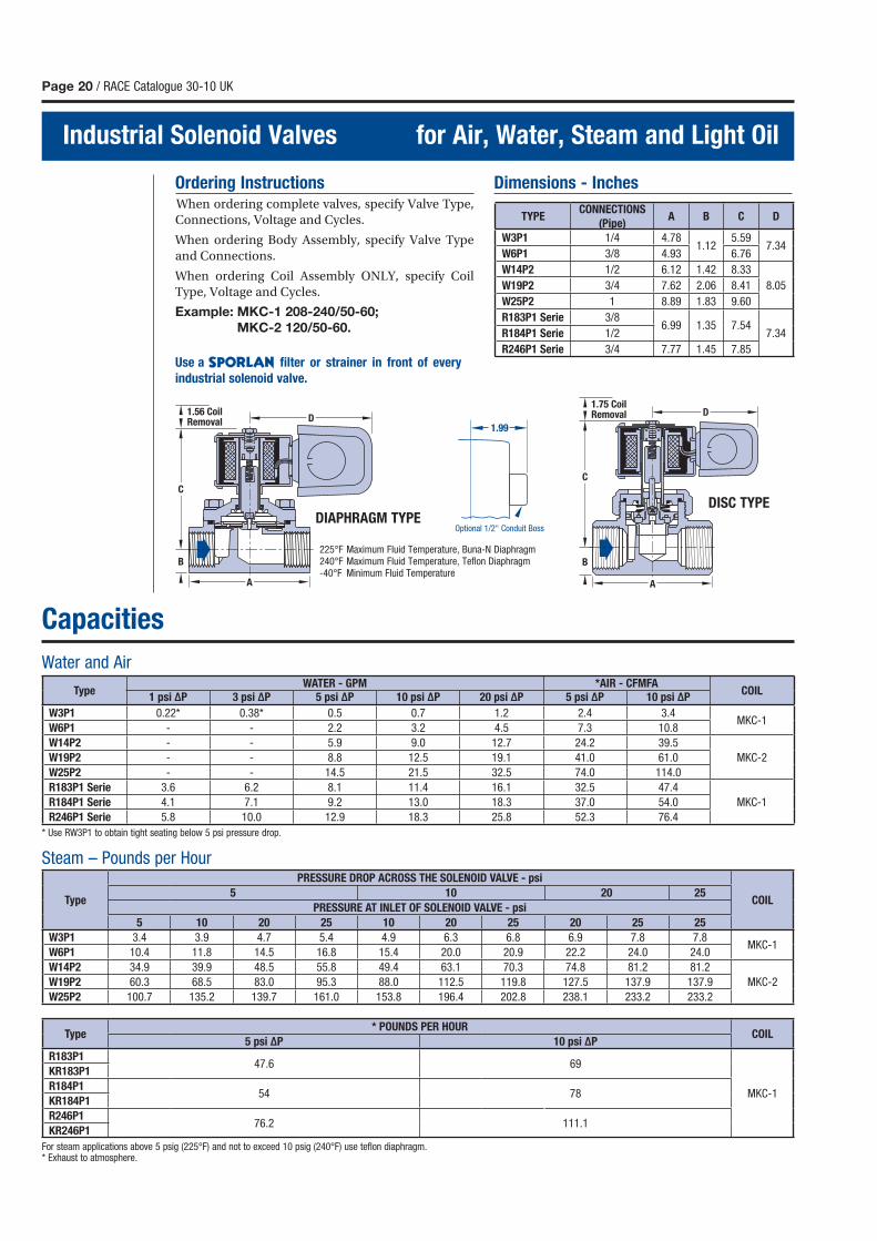
Page 20 / RACE Catalogue 30-10 UK
Industrial Solenoid Valves for Air, Water, Steam and Light Oil
1.56 CoilRemoval D
B
C
A
1.75 CoilRemoval D
DB
C
A
225°F Maximum Fluid Temperature, Buna-N Diaphragm 240°F Maximum Fluid Temperature, Teflon Diaphragm -40°F Minimum Fluid Temperature
Ordering Instructions
When ordering complete valves, specify Valve Type,
Connections, Voltage and Cycles.
When ordering Body Assembly, specify Valve Type
and Connections.
When ordering Coil Assembly ONLY, specify Coil
Type, Voltage and Cycles.
Example: MKC-1 208-240/50-60;
MKC-2 120/50-60.
Dimensions - Inches
Capacities
For steam applications above 5 psig (225°F) and not to exceed 10 psig (240°F) use teflon diaphragm.* Exhaust to atmosphere.
Steam – Pounds per Hour
Water and Air
* Use RW3P1 to obtain tight seating below 5 psi pressure drop.
DISC TYPEDIAPHRAGM TYPE
Optional 1/2" Conduit Boss
1.99
Use a filter or strainer in front of every
industrial solenoid valve.
TYPECONNECTIONS
(Pipe)A B C D
W3P1 1/4 4.781.12
5.597.34
W6P1 3/8 4.93 6.76
W14P2 1/2 6.12 1.42 8.33
8.05W19P2 3/4 7.62 2.06 8.41
W25P2 1 8.89 1.83 9.60
R183P1 Serie 3/86.99 1.35 7.54
7.34R184P1 Serie 1/2
R246P1 Serie 3/4 7.77 1.45 7.85
TypeWATER - GPM *AIR - CFMFA
COIL1 psi ΔP 3 psi ΔP 5 psi ΔP 10 psi ΔP 20 psi ΔP 5 psi ΔP 10 psi ΔP
W3P1 0.22* 0.38* 0.5 0.7 1.2 2.4 3.4MKC-1
W6P1 - - 2.2 3.2 4.5 7.3 10.8
W14P2 - - 5.9 9.0 12.7 24.2 39.5
MKC-2W19P2 - - 8.8 12.5 19.1 41.0 61.0
W25P2 - - 14.5 21.5 32.5 74.0 114.0
R183P1 Serie 3.6 6.2 8.1 11.4 16.1 32.5 47.4
MKC-1R184P1 Serie 4.1 7.1 9.2 13.0 18.3 37.0 54.0
R246P1 Serie 5.8 10.0 12.9 18.3 25.8 52.3 76.4
Type
PRESSURE DROP ACROSS THE SOLENOID VALVE - psi
COIL5 10 20 25
PRESSURE AT INLET OF SOLENOID VALVE - psi
5 10 20 25 10 20 25 20 25 25
W3P1 3.4 3.9 4.7 5.4 4.9 6.3 6.8 6.9 7.8 7.8MKC-1
W6P1 10.4 11.8 14.5 16.8 15.4 20.0 20.9 22.2 24.0 24.0
W14P2 34.9 39.9 48.5 55.8 49.4 63.1 70.3 74.8 81.2 81.2
MKC-2W19P2 60.3 68.5 83.0 95.3 88.0 112.5 119.8 127.5 137.9 137.9
W25P2 100.7 135.2 139.7 161.0 153.8 196.4 202.8 238.1 233.2 233.2
Type* POUNDS PER HOUR
COIL5 psi ΔP 10 psi ΔP
R183P147.6 69
MKC-1
KR183P1
R184P154 78
KR184P1
R246P176.2 111.1
KR246P1
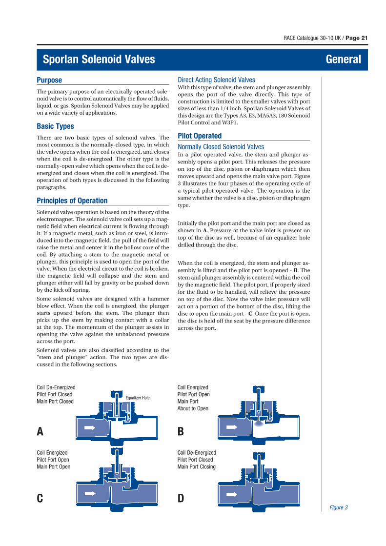
RACE Catalogue 30-10 UK / Page 21
Sporlan Solenoid Valves General
Purpose
The primary purpose of an electrically operated sole-
noid valve is to control automatically the flow of fluids,
liquid, or gas. Sporlan Solenoid Valves may be applied
on a wide variety of applications.
Basic Types
There are two basic types of solenoid valves. The
most common is the normally-closed type, in which
the valve opens when the coil is energized, and closes
when the coil is de-energized. The other type is the
normally-open valve which opens when the coil is de-
energized and closes when the coil is energized. The
operation of both types is discussed in the following
paragraphs.
Principles of Operation
Solenoid valve operation is based on the theory of the
electromagnet. The solenoid valve coil sets up a mag-
netic field when electrical current is flowing through
it. If a magnetic metal, such as iron or steel, is intro-
duced into the magnetic field, the pull of the field will
raise the metal and center it in the hollow core of the
coil. By attaching a stem to the magnetic metal or
plunger, this principle is used to open the port of the
valve. When the electrical circuit to the coil is broken,
the magnetic field will collapse and the stem and
plunger either will fall by gravity or be pushed down
by the kick off spring.
Some solenoid valves are designed with a hammer
blow effect. When the coil is energized, the plunger
starts upward before the stem. The plunger then
picks up the stem by making contact with a collar
at the top. The momentum of the plunger assists in
opening the valve against the unbalanced pressure
across the port.
Solenoid valves are also classified according to the
"stem and plunger" action. The two types are dis-
cussed in the following sections.
Direct Acting Solenoid ValvesWith this type of valve, the stem and plunger assembly
opens the port of the valve directly. This type of
construction is limited to the smaller valves with port
sizes of less than 1/4 inch. Sporlan Solenoid Valves of
this design are the Types A3, E3, MA5A3, 180 Solenoid
Pilot Control and W3P1.
Pilot Operated
Normally Closed Solenoid ValvesIn a pilot operated valve, the stem and plunger as-
sembly opens a pilot port. This releases the pressure
on top of the disc, piston or diaphragm which then
moves upward and opens the main valve port. Figure
3 illustrates the four phases of the operating cycle of
a typical pilot operated valve. The operation is the
same whether the valve is a disc, piston or diaphragm
type.
Initially the pilot port and the main port are closed as
shown in A. Pressure at the valve inlet is present on
top of the disc as well, because of an equalizer hole
drilled through the disc.
When the coil is energized, the stem and plunger as-
sembly is lifted and the pilot port is opened - B. The
stem and plunger assembly is centered within the coil
by the magnetic field. The pilot port, if properly sized
for the fluid to be handled, will relieve the pressure
on top of the disc. Now the valve inlet pressure will
act on a portion of the bottom of the disc, lifting the
disc to open the main port - C. Once the port is open,
the disc is held off the seat by the pressure difference
across the port.
Figure 3
Coil Energized
Pilot Port Open
Main Port
About to Open
B
Coil Energized
Pilot Port Open
Main Port Open
C
Coil De-Energized
Pilot Port Closed
Main Port Closing
D
Coil De-Energized
Pilot Port Closed
Main Port Closed
A
Equalizer Hole
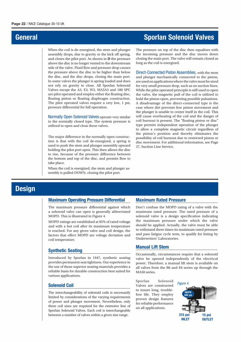
Maximum Operating Pressure Differential
The maximum pressure differential against which
a solenoid valve can open is generally abbreviated
MOPD. This is illustrated in Figure 4.
MOPD ratings are established at 85% of rated voltage
and with a hot coil after its maximum temperature
is reached. For any given valve and coil design, the
factors that effect MOPD are voltage deviation and
coil temperature.
Synthetic Seating
Introduced by Sporlan in 1947, synthetic seating
provides permanent seat tightness. Our experience in
the use of these superior seating materials provides a
reliable basis for durable construction best suited for
various applications.
Solenoid Coil
The interchangeability of solenoid coils is necessarily
limited by considerations of the varying requirements
of power and plunger movement. Nevertheless, only
three coil sizes are required for the extensive line of
Sporlan Solenoid Valves. Each coil is interchangeable
between a number of valves within a given size range.
Maximum Rated Pressure
Don’t confuse the MOPD rating of a valve with the
maximum rated pressure. The rated pressure of a
solenoid valve is a design specification indicating
the maximum pressure under which the valve
should be applied. Actually, the valve must be able
to withstand three times its maximum rated pressure
and pass fatigue cycle tests, to qualify for listing by
Underwriters’ Laboratories.
Manual Lift Stem
Occasionally, circumstances require that a solenoid
valve be opened independently of the electrical
power. Therefore, a manual lift stem is available on
all valves from the B6 and E6 series up through the
MA50 series.
Sporlan Solenoid
Valves are constructed
to insure long, trouble-
free life. They employ
proven design features
for reliable performance
on all applications.
Page 22 / RACE Catalogue 30-10 UK
General Sporlan Solenoid Valves
When the coil is de-energized, the stem and plunger
assembly drops, due to gravity or the kick off spring,
and closes the pilot port. As shown in D the pressure
above the disc is no longer vented to the downstream
side of the valve. Fluid flow and pressure drop causes
the pressure above the disc to be higher than below
the disc, and the disc drops, closing the main port.
In some valves the plunger is spring loaded and does not rely on gravity to close. All Sporlan Solenoid Valves except the A3, E3, W3, MA5A3 and 180 SPC are pilot operated and employ either the floating disc, floating piston or floating diaphragm construction. The pilot operated valves require a very low, 1 psi, pressure differential for full operation.
Normally Open Solenoid Valves operate very similar to the normally closed type. The system pressure is utilized to open and close these valves.
The major difference in the normally open construc-tion is that with the coil de-energized, a spring is used to push the stem and plunger assembly upward holding the pilot port open. This then allows the disc to rise, because of the pressure difference between the bottom and top of the disc, and permits flow to take place.
When the coil is energized, the stem and plunger as-sembly is pulled DOWN, closing the pilot port.
The pressure on top of the disc then equalizes with the incoming pressure and the disc moves down closing the main port. The valve will remain closed as long as the coil is energized.
Direct-Connected Piston Assemblies, with the stem and plunger mechanically connected to the piston, are used on applications where the valve must be sized for very small pressure drop, such as on suction lines. While the pilot operated principle is still used to open the valve, the magnetic pull of the coil is utilized to hold the piston open, preventing possible pulsations. A disadvantage of the direct-connected type is the case where dirt prevents free piston movement and the plunger is unable to center itself in the coil. This will cause overheating of the coil and the danger of coil burnout is present. The "floating piston or disc" type permits independent operation of the plunger to allow a complete magnetic circuit regardless of the piston’s position and thereby eliminates the possibility of coil burnout due to restricted piston or disc movement. For additional information, see Page 27, Suction Line Service.
Design
315 psi
INLET15 psi
OUTLET
Figure 4
MOPD300 psi
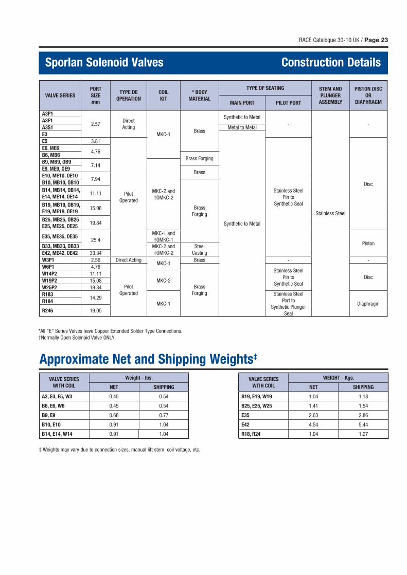
RACE Catalogue 30-10 UK / Page 23
Sporlan Solenoid Valves Construction Details
*All "E" Series Valves have Copper Extended Solder Type Connections.
†Normally Open Solenoid Valve ONLY.
Approximate Net and Shipping Weights‡
‡ Weights may vary due to connection sizes, manual lift stem, coil voltage, etc.
VALVE SERIES
PORT
SIZE
mm
TYPE DE
OPERATION
COIL
KIT
* BODY
MATERIAL
TYPE OF SEATING STEM AND
PLUNGER
ASSEMBLY
PISTON DISC
OR
DIAPHRAGMMAIN PORT PILOT PORT
A3P1
2.57Direct
Acting
MKC-1Brass
Synthetic to Metal
-
Stainless Steel
-A3F1
A3S1 Metal to Metal
E3
Synthetic to Metal
E5 3.81
Pilot
Operated
Stainless Steel
Pin to
Synthetic Seal
Disc
E6, ME64.76
B6, MB6Brass Forging
B9, MB9, OB97.14
MKC-2 and
†OMKC-2
E9, ME9, OE9Brass
E10, ME10, OE107.94
B10, MB10, OB10
Brass
Forging
B14, MB14, OB14,
E14, ME14, OE1411.11
B19, MB19, OB19,
E19, ME19, OE1915.08
B25, MB25, OB25
E25, ME25, OE2519.84
E35, ME35, OE3525.4
MKC-1 and
†OMKC-1Piston
B33, MB33, OB33 MKC-2 and
†OMKC-2
Steel
CastingE42, ME42, OE42 33.34
W3P1 2.56 Direct ActingMKC-1
Brass - -
W6P1 4.76
Pilot
Operated
Brass
Forging
Stainless Steel
Pin to
Synthetic Seal
DiscW14P2 11.11
MKC-2W19P2 15.08
W25P2 19.84
R18314.29
MKC-1
Stainless Steel
Port to
Synthetic Plunger
Seal
DiaphragmR184
R246 19.05
VALVE SERIES
WITH COIL
Weight - lbs. VALVE SERIES
WITH COIL
WEIGHT - Kgs.
NET SHIPPING NET SHIPPING
A3, E3, E5, W3 0.45 0.54 B19, E19, W19 1.04 1.18
B6, E6, W6 0.45 0.54 B25, E25, W25 1.41 1.54
B9, E9 0.68 0.77 E35 2.63 2.86
B10, E10 0.91 1.04 E42 4.54 5.44
B14, E14, W14 0.91 1.04 R18, R24 1.04 1.27
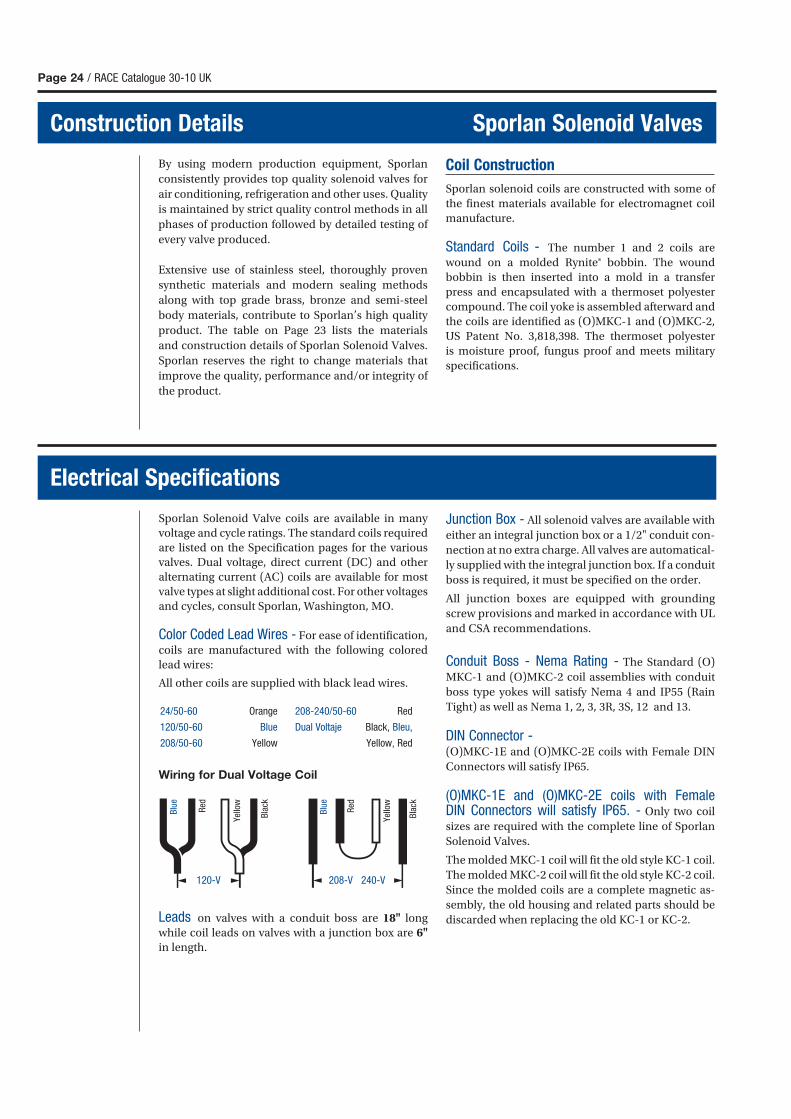
Page 24 / RACE Catalogue 30-10 UK
Construction Details Sporlan Solenoid Valves
By using modern production equipment, Sporlan
consistently provides top quality solenoid valves for
air conditioning, refrigeration and other uses. Quality
is maintained by strict quality control methods in all
phases of production followed by detailed testing of
every valve produced.
Extensive use of stainless steel, thoroughly proven
synthetic materials and modern sealing methods
along with top grade brass, bronze and semi-steel
body materials, contribute to Sporlan’s high quality
product. The table on Page 23 lists the materials
and construction details of Sporlan Solenoid Valves.
Sporlan reserves the right to change materials that
improve the quality, performance and/or integrity of
the product.
Coil Construction
Sporlan solenoid coils are constructed with some of
the finest materials available for electromagnet coil
manufacture.
Standard Coils - The number 1 and 2 coils are
wound on a molded Rynite® bobbin. The wound
bobbin is then inserted into a mold in a transfer
press and encapsulated with a thermoset polyester
compound. The coil yoke is assembled afterward and
the coils are identified as (O)MKC-1 and (O)MKC-2,
US Patent No. 3,818,398. The thermoset polyester
is moisture proof, fungus proof and meets military
specifications.
Sporlan Solenoid Valve coils are available in many
voltage and cycle ratings. The standard coils required
are listed on the Specification pages for the various
valves. Dual voltage, direct current (DC) and other
alternating current (AC) coils are available for most
valve types at slight additional cost. For other voltages
and cycles, consult Sporlan, Washington, MO.
Color Coded Lead Wires - For ease of identification,
coils are manufactured with the following colored
lead wires:
All other coils are supplied with black lead wires.
Wiring for Dual Voltage Coil
Leads on valves with a conduit boss are 18" long
while coil leads on valves with a junction box are 6"
in length.
Junction Box - All solenoid valves are available with
either an integral junction box or a 1/2" conduit con-
nection at no extra charge. All valves are automatical-
ly supplied with the integral junction box. If a conduit
boss is required, it must be specified on the order.
All junction boxes are equipped with grounding
screw provisions and marked in accordance with UL
and CSA recommendations.
Conduit Boss - Nema Rating - The Standard (O)
MKC-1 and (O)MKC-2 coil assemblies with conduit
boss type yokes will satisfy Nema 4 and IP55 (Rain
Tight) as well as Nema 1, 2, 3, 3R, 3S, 12 and 13.
DIN Connector -(O)MKC-1E and (O)MKC-2E coils with Female DIN
Connectors will satisfy IP65.
(O)MKC-1E and (O)MKC-2E coils with Female DIN Connectors will satisfy IP65. - Only two coil
sizes are required with the complete line of Sporlan
Solenoid Valves.
The molded MKC-1 coil will fit the old style KC-1 coil.
The molded MKC-2 coil will fit the old style KC-2 coil.
Since the molded coils are a complete magnetic as-
sembly, the old housing and related parts should be
discarded when replacing the old KC-1 or KC-2.
Electrical Specifications
120-V 208-V 240-V
Blu
e
Red
Yello
w
Bla
ck
Blu
e
Red
Yello
w
Bla
ck
24/50-60 Orange
120/50-60 Blue
208/50-60 Yellow
208-240/50-60 Red
Dual Voltaje Black, Bleu,
Yellow, Red
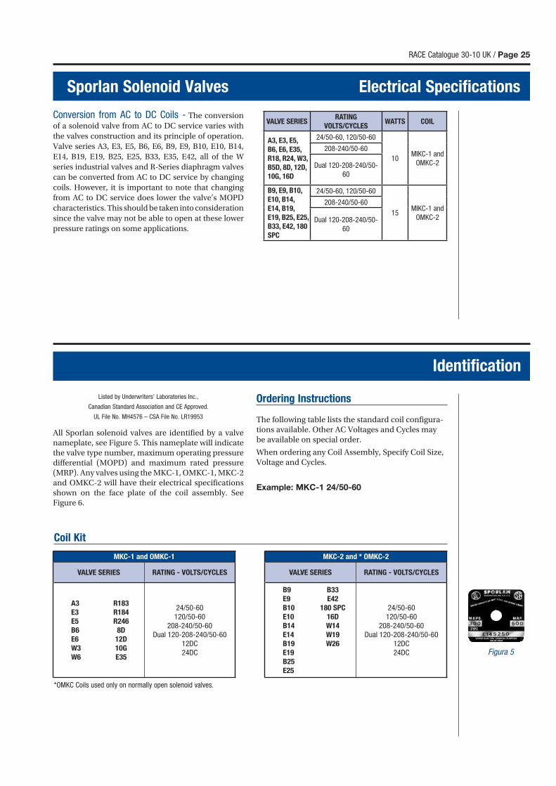
RACE Catalogue 30-10 UK / Page 25
Sporlan Solenoid Valves Electrical Specifications
Conversion from AC to DC Coils - The conversion
of a solenoid valve from AC to DC service varies with
the valves construction and its principle of operation.
Valve series A3, E3, E5, B6, E6, B9, E9, B10, E10, B14,
E14, B19, E19, B25, E25, B33, E35, E42, all of the W
series industrial valves and R-Series diaphragm valves
can be converted from AC to DC service by changing
coils. However, it is important to note that changing
from AC to DC service does lower the valve’s MOPD
characteristics. This should be taken into consideration
since the valve may not be able to open at these lower
pressure ratings on some applications.
Identification
Listed by Underwriters’ Laboratories Inc.,
Canadian Standard Association and CE Approved.
UL File No. MH4576 – CSA File No. LR19953
All Sporlan solenoid valves are identified by a valve nameplate, see Figure 5. This nameplate will indicate the valve type number, maximum operating pressure differential (MOPD) and maximum rated pressure (MRP). Any valves using the MKC-1, OMKC-1, MKC-2 and OMKC-2 will have their electrical specifications shown on the face plate of the coil assembly. See Figure 6.
Ordering Instructions
The following table lists the standard coil configura-tions available. Other AC Voltages and Cycles may be available on special order.
When ordering any Coil Assembly, Specify Coil Size, Voltage and Cycles.
Example: MKC-1 24/50-60
Figura 5
*OMKC Coils used only on normally open solenoid valves.
Coil Kit
VALVE SERIESRATING
VOLTS/CYCLESWATTS COIL
A3, E3, E5,
B6, E6, E35,
R18, R24, W3,
B5D, 8D, 12D,
10G, 16D
24/50-60, 120/50-60
10MIKC-1 and
OMKC-2
208-240/50-60
Dual 120-208-240/50-
60
B9, E9, B10,
E10, B14,
E14, B19,
E19, B25, E25,
B33, E42, 180
SPC
24/50-60, 120/50-60
15MIKC-1 and
OMKC-2
208-240/50-60
Dual 120-208-240/50-
60
MKC-1 and OMKC-1 MKC-2 and * OMKC-2
VALVE SERIES RATING - VOLTS/CYCLES VALVE SERIES RATING - VOLTS/CYCLES
A3 R183
E3 R184
E5 R246
B6 8D
E6 12D
W3 10G
W6 E35
24/50-60
120/50-60
208-240/50-60
Dual 120-208-240/50-60
12DC
24DC
B9 B33
E9 E42
B10 180 SPC
E10 16D
B14 W14
E14 W19
B19 W26
E19
B25
E25
24/50-60
120/50-60
208-240/50-60
Dual 120-208-240/50-60
12DC
24DC
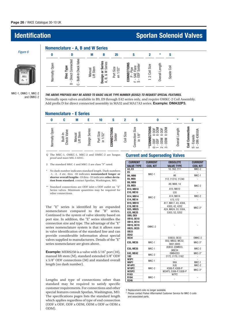
O D M B 52 S 2 * S
Page 26 / RACE Catalogue 30-10 UK
Identification Sporlan Solenoid Valves
MKC-1, OMKC-1, MKC-2
and OMKC-2
Figure 6Nomenclature - A, B and W Series
Nor
mal
ly O
pen
Dis
c T
ype
D -
Dire
ct C
onne
cted
C -
Built
-In C
heck
Val
ve
Man
ual
Lift
Ste
m
Des
ign
or
Ser
ies
A,
B,
& W
Ser
ies
Por
t S
ize
en 1
/32
"
CO
NN
EC
TIO
NS
P -
Pip
e
F -
SA
E Fl
are
S
- O
DF
Sol
der
1 2
Coi
l Siz
e
Ove
rall
Leng
th
Spa
de C
oil
THE ABOVE PREFIXES MAY BE ADDED TO BASIC VALVE TYPE NUMBER (B25S2) TO REQUEST SPECIAL FEATURES.
Normally open valves available in B9, E9 through E42 series only, and require OMKC-2 Coil Assembly.Add prefix D for direct connected assembly in MA32 and MA17A3 series. Example: DMA32P3.
Q The MKC-1, OMKC-1, MKC-2 and OMKC-2 are fungus
proof and meet MIL-I-631C.
2 The standard MKC-1 and MKC-2 are class "F" rated.
* No dash number indicates standard length. Dash numbers
-1, -2, -3 etc. thru -18 indicates nonstandard longer or
shorter overall lengths -19 thru -33 indicates other devia-
tion from standard, contact Sporlan, Washington, MO.
** Standard connections are ODF inlet x ODF outlet on ‘’E"
Series valves. Minimum quantities may be required for
other connections.
Nomenclature - E Series
O C M E 01 S 2 5 0 * S
Nor
mal
ly O
pen
Man
ual
Lift
Ste
m
Des
ign
Ser
ies
Por
t S
ize
in 1
/32
"
CO
NN
EC
TIO
NS
Sol
der
Coi
l Siz
e
Con
nect
ion
Siz
e
in 1
/8"
**C
ON
NE
CT
ION
S
0
- O
DF
X O
DF
1
- O
DF
X O
DM
2
- O
DM
X
OD
F
3
- O
DM
X
OD
M
Ove
rall
Leng
th
Co
il C
on
nec
tio
n
S
- E
spad
a
E
- D
IN 4
36
50
A
Bui
lt-In
Che
ck V
alve
The "E" series is identified by an expanded nomenclature compared to the "B" series. Continued is the system of valve identity based on port size. In addition, the "E" series identifies the connection size and type. The advantage of the "E" series nomenclature system is that it allows ease in valve identification of the standard line and can provide considerable information about special valves supplied to manufacturers. Details of the "E" series nomenclature are given above.
Example: MEl0S250 is a valve with 5/16" port (10), manual lift stem (M), standard extended 5/8" ODF x 5/8" ODF connections (50) and standard overall length (no dash number).
Lengths and type of connections other than standard may be required to satisfy specific customer requirements. For connections and other special features consult Sporlan, Washington, MO. The specifications pages lists the standard length which applies regardless of type of end connection (ODF x ODF, ODF x ODM, ODM x ODF or ODM x ODM).
† Replacement coils no longer available.
* Please contact Parker Aftermarket Customer Service for MKC-3 coils
and associated parts.
Current and Superseding Valves
CURRENT
VALVE TYPE
CURRENT
COIL KIT
OBSOLETE
VALVE TYPE
CURRENT
COIL KITA3, E3
MKC-1
10, †62, †11 MKC-2E5 - -
B6, MB6
E6, ME6
A6 MKC-1
†12, †1210, †1240 -
B9, MB9
E9, ME9
MKC-2
A9, MA9, 14MKC-2
B10, MB10
E10, ME10
A10, MA10
†20 -
B14, MB14
E14, ME14
A14, MA14 MKC-2
†73, †72 -
B19, MB19
E19, ME19
A17, MA17, 43, 4304,
4303, 42, 4202MKC-3*
B25, MB25
E25, ME25
A24, MA24, 53, 5304,
5303, 52, 5202OB9, OE9
OB10, OE10
OB14, OE14
OB19, OE19
OB25, OE25
OB33
OE42
OMKC-2- -
OE34 EOB33, OE33 OMKC-2
E35, ME35 MKC-1B32, MB32, MC32,
9001,9005MKC-3*
E35, ME35 MKC-1(E)B33, (E)MB33,
(M)E34MKC-2
E42, ME42MKC-2
EMB42S3 MKC-3*180 †172, †170, †162 -W3P1
MKC-1- -
W6P1 XKA MKC-1W14P2
MKC-2XJQ MKC-2
W19P2 4306-P, 4308-PMKC-3*
W25P2 W24P3, 5306-P, 5308-PR183
MKC-1W7P2
-R184-
R246
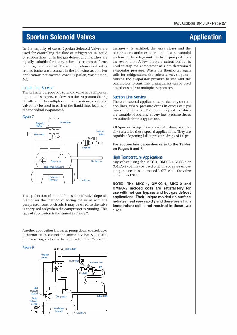
thermostat is satisfied, the valve closes and the
compressor continues to run until a substantial
portion of the refrigerant has been pumped from
the evaporator. A low pressure cutout control is
used to stop the compressor at a pre-determined
evaporator pressure. When the thermostat again
calls for refrigeration, the solenoid valve opens -
causing the evaporator pressure to rise and the
compressor to start. This arrangement can be used
on either single or multiple evaporators.
Suction Line ServiceThere are several applications, particularly on suc-tion lines, where pressure drops in excess of 2 psi cannot be tolerated. Therefore, only valves which are capable of opening at very low pressure drops are suitable for this type of use.
All Sporlan refrigeration solenoid valves, are ide-ally suited for these special applications. They are capable of opening full at pressure drops of 1.0 psi.
For suction line capacities refer to the Tables
on Pages 6 and 7.
High Temperature ApplicationsAny valves using the MKC-1, OMKC-1, MKC-2 or
OMKC-2 coil may be used on fluids or gases whose
temperature does not exceed 240°F, while the valve
ambient is 120°F.
NOTE: The MKC-1, OMKC-1, MKC-2 and
OMKC-2 molded coils are satisfactory for
use with hot gas bypass and hot gas defrost
applications. Their unique molded rib surface
radiates heat very rapidly and therefore a high
temperature coil is not required in these two
sizes.
RACE Catalogue 30-10 UK / Page 27
Sporlan Solenoid Valves Application
In the majority of cases, Sporlan Solenoid Valves are
used for controlling the flow of refrigerants in liquid
or suction lines, or in hot gas defrost circuits. They are
equally suitable for many other less common forms
of refrigerant control. These applications and other
related topics are discussed in the following section. For
applications not covered, consult Sporlan, Washington,
MO.
Liquid Line ServiceThe primary purpose of a solenoid valve in a refrigerant
liquid line is to prevent flow into the evaporator during
the off-cycle. On multiple evaporator systems, a solenoid
valve may be used in each of the liquid lines leading to
the individual evaporators.
Line VoltageMagnetic
Starter
Thermostat
Solenoid
Valve
Catch-All
Suction LineCompressor
Liquid Line
Condenser
Receiver
Dual Pressure Control
Figure 7
Figure 8
CondenserReceiver
Line Voltage
Magnetic
Starter
Catch-All
Suction LineCompressor
Liquid Line
Thermostat
DualPressure
Control
Water Solenoid
Control
Solenoid Valve
TEV
The application of a liquid line solenoid valve depends
mainly on the method of wiring the valve with the
compressor control circuit. It may be wired so the valve
is energized only when the compressor is running. This
type of application is illustrated in Figure 7.
Another application known as pump down control, uses
a thermostat to control the solenoid valve. See Figure
8 for a wiring and valve location schematic. When the
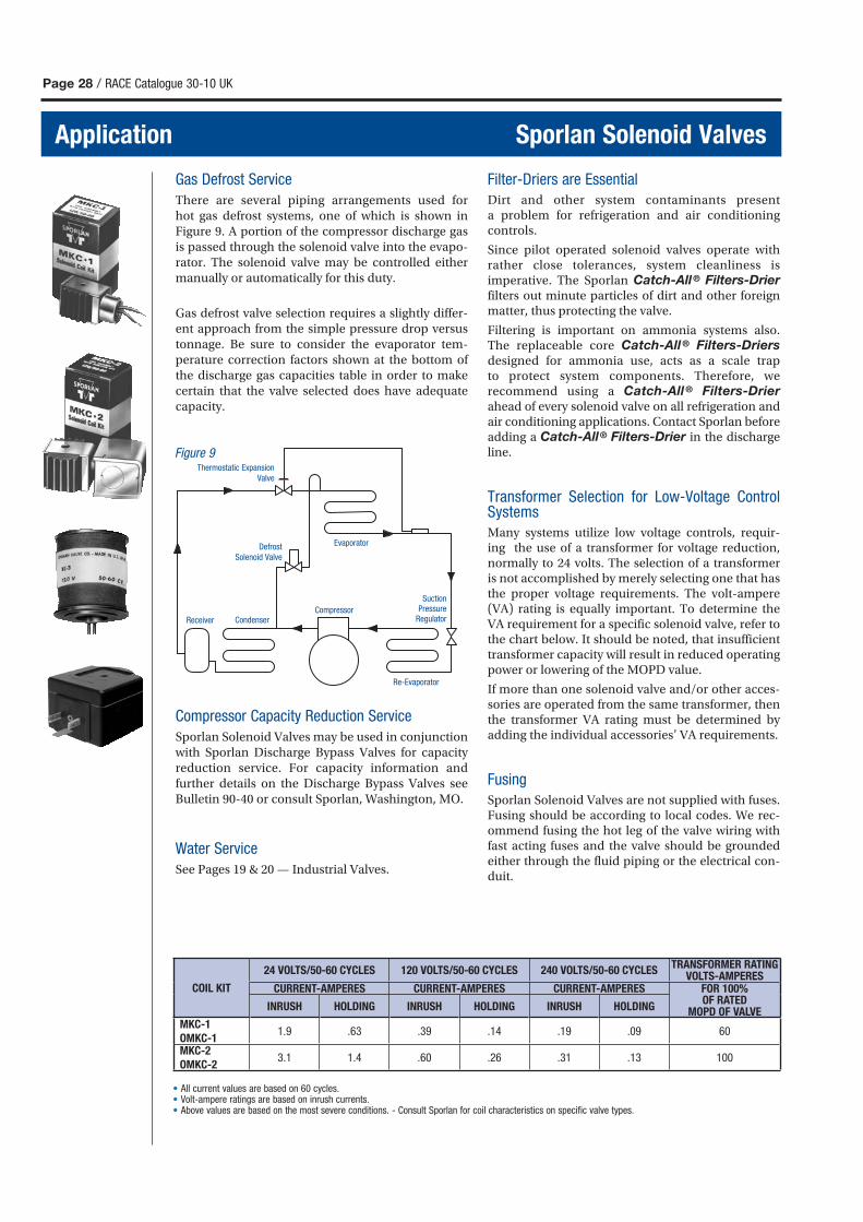
Page 28 / RACE Catalogue 30-10 UK
Application Sporlan Solenoid Valves
• All current values are based on 60 cycles.• Volt-ampere ratings are based on inrush currents.• Above values are based on the most severe conditions. - Consult Sporlan for coil characteristics on specific valve types.
Gas Defrost Service
There are several piping arrangements used for hot gas defrost systems, one of which is shown in Figure 9. A portion of the compressor discharge gas is passed through the solenoid valve into the evapo-rator. The solenoid valve may be controlled either manually or automatically for this duty.
Gas defrost valve selection requires a slightly differ-ent approach from the simple pressure drop versus tonnage. Be sure to consider the evaporator tem-perature correction factors shown at the bottom of the discharge gas capacities table in order to make certain that the valve selected does have adequate capacity.
Compressor Capacity Reduction Service
Sporlan Solenoid Valves may be used in conjunction with Sporlan Discharge Bypass Valves for capacity reduction service. For capacity information and further details on the Discharge Bypass Valves see Bulletin 90-40 or consult Sporlan, Washington, MO.
Water Service
See Pages 19 & 20 — Industrial Valves.
Filter-Driers are Essential
Dirt and other system contaminants present a problem for refrigeration and air conditioning controls.
Since pilot operated solenoid valves operate with rather close tolerances, system cleanliness is imperative. The Sporlan Catch-All® Filters-Drier filters out minute particles of dirt and other foreign matter, thus protecting the valve.
Filtering is important on ammonia systems also. The replaceable core Catch-All® Filters-Driers designed for ammonia use, acts as a scale trap to protect system components. Therefore, we recommend using a Catch-All ® Filters-Drier ahead of every solenoid valve on all refrigeration and air conditioning applications. Contact Sporlan before adding a Catch-All® Filters-Drier in the discharge line.
Transformer Selection for Low-Voltage Control Systems
Many systems utilize low voltage controls, requir-ing the use of a transformer for voltage reduction, normally to 24 volts. The selection of a transformer is not accomplished by merely selecting one that has the proper voltage requirements. The volt-ampere (VA) rating is equally important. To determine the VA requirement for a specific solenoid valve, refer to the chart below. It should be noted, that insufficient transformer capacity will result in reduced operating power or lowering of the MOPD value.
If more than one solenoid valve and/or other acces-sories are operated from the same transformer, then the transformer VA rating must be determined by adding the individual accessories’ VA requirements.
Fusing
Sporlan Solenoid Valves are not supplied with fuses. Fusing should be according to local codes. We rec-ommend fusing the hot leg of the valve wiring with fast acting fuses and the valve should be grounded either through the fluid piping or the electrical con-duit.
Figure 9
Evaporator
SuctionPressure
Regulator
Re-Evaporator
CompressorReceiver
Thermostatic Expansion
Valve
Defrost
Solenoid Valve
Condenser
COIL KIT
24 VOLTS/50-60 CYCLES 120 VOLTS/50-60 CYCLES 240 VOLTS/50-60 CYCLESTRANSFORMER RATING
VOLTS-AMPERESCURRENT-AMPERES CURRENT-AMPERES CURRENT-AMPERES FOR 100%
OF RATEDMOPD OF VALVEINRUSH HOLDING INRUSH HOLDING INRUSH HOLDING
MKC-1
OMKC-11.9 .63 .39 .14 .19 .09 60
MKC-2
OMKC-23.1 1.4 .60 .26 .31 .13 100
Parker Hannifi n Ltd
Climate and Industrial Controls Group
Refrigeration and Air Conditioning Europe
Cortonwood Drive, Brampton
South Yorkshire S73 OUF
United Kingdom
phone +44 (0) 1226 273400
fax +44 (0) 1226 273401
www.parker.com/race RACE Catalogue 30-10 UK - 04/2010 - Zalsman