Embed Size (px)
Citation preview

FLEXI/O AND FLEX EXSELECTION GUIDE
1794 selection guide cover.qxp 10/30/2007 3:10 PM Page 2

2
Publication 1794-SG002C-EN-P — October 2007
FLEX I/OOverview
FLEX I/O offers:
FLEX I/O complements all of our processor platforms and acts as local I/O forFlexLogix controllers, creating a tightly integrated control and I/O solution.
Flexible, low-cost, modular I/O for distributed applications. FLEX I/O offersall the functions of larger, rack-based I/O without the space requirements.Independently select the I/O, termination style, and network to meet your applicationneeds.
Two separate connection terminals for field power let you daisy-chain powerconnections to adjacent terminal bases.
One adapter communicates with up to eight I/O modules. Allows connectionto:
� 256 digital input/output points, or
� 96 analog input/output points, or
� mix of I/O to meet your needs.
Modularity of FLEX I/O system provides choice of network and ease of expansion.
The wiring terminations are done almost entirely on the terminal base.
Terminal base termination selection includes screw-clamp, spring-clamp, andcage-clamp to wire directly to 2-, 3-, or 4-wire devices. Additional options of D-shell,knife disconnect, and fused are available.
Adjustable keyswitch prevents incorrect module insertion into a preconfiguredterminal base.
Terminal bases can be exchanged without moving other bases in your system.

3
Publication 1794-SG002C-EN-P — October 2007
If desired, connect individual power supplies to each base to isolate modules.
Plug the I/O module into the terminal base to connect the I/O bus and fielddevices.
Remove and insert modules under power. No direct wiring to the moduleenables you to change modules without disturbing field wiring or system power.
Mix and match I/O modules. Wide variety of digital, analog, and specialty modules.
Conformal coating available in select FLEX I/O products.
Each FLEX I/O system contains at least one adapter, terminal base, and I/O module.You can power the system with a FLEX power supply (1794-PS13 or -PS3) or anyother compatible power source. Use the terminal block on the terminal base to wireyour field devices directly. Wiring directly saves you:
� installation and testing time
� multiple, long wiring runs and external terminal blocks
� control cabinet panel space
FLEX I/O provides additional savings if system problems develop. Combining yourfield-wiring terminations and the I/O interface into the same location saves you timeand money by making your system easier to maintain and troubleshoot. Additionally,the full-featured FLEX I/O system lets you, in non-hazardous location, remove andinsert modules under backplane power without disrupting your system.
Your FLEX I/O system can communicate on EtherNet/IP, ControlNet, DeviceNet, andmany other open networks including, but not limited, to Remote I/O, PROFIBUS DP,and Interbus-S. Adapters and other components are available for adding to yoursystem as your specific application requirements change.

4
Publication 1794-SG002C-EN-P — October 2007
FFLLEEXX II//OO GGeenneerraallSSppeecciiffiiccaattiioonnss
The following specifications apply to all FLEX I/O adapters, modules, and terminalbases. For all other specifications, refer to the specific product catalog numbersections in this selection guide.
�
Operating Temperature 0…55 °C (32…131 °F)
Non-Operating Temperature -40…85 °C (-40…185 °F)
Relative Humidity 5…95% non-condensing
Shock, Operating�✶ 30 g peak acceleration, 11(±1) ms pulse width✶
Shock, Non-Operating� 50 g peak acceleration, 11(±1) ms pulse width
Vibration Tested 5 g @ 10…500 Hz per IEC 68-2-6�
Wire Size22…12 AWG (0.34 mm2…2.5 mm2) stranded copper wire rated at 75 °C or higher 3/64 in (1.2 mm) insulation max.�
Certifications‡
UL Listed Industrial Control Equipment UL Listed for Class I, Division 2 Groups A, B, C, D Hazardous LocationsCE Marked for all applicable directivesCE / ATEXTCSA Certified Process Control Equipment for Class I, Division 2 Group A, B, C, D Hazardous LocationsC-Tick Marked for all applicable actsMarine CertificationSIL 2 CertificationODVAControlNet
✶ 1794-OW8 = 12 g peak acceleration, 11(±1) ms pulse width.� 1794-OW8 = Tested 2 g @ 10…500 Hz per IEC 68-2-6.‡When product is marked.§See the CE Marking - Declaration of Conformity (DoC) web site for details and a list of certified products.♣See the Certification for Marine and Off-shore Applications web site for details and a list of certified products.➤See the SIL 2 web site for details and a list of certified products.�To maintain these specifications, you must use DIN Rail locks.�For all other specifications including environmetal, refer to the product sections in this Selection Guide.
CCoonnffoorrmmaall CCooaatteeddFFlleexx II//OO
Selected products in the FLEX I/O product line are available conformally coated asstandard, stocked product. Catalog numbers of conformally coated product willinclude the designation “K” in the last position before the series identifier.
For example: A 1794 IB16/A Module with conformal coating would have the catalognumber 1794 IB16K/A.
FLEX I/O’s Conformal Coating meets or exceeds the following standards:
� ANSI / ISA-S71.04-1985; Class G1, G2 and G3 Environments
� CEI IEC 6065A-4; Class 1 and 2 Environments
� UL 746E
� MIL-1-46058C to ASTM-G21; (Tropicalization and fungicide)

5
Publication 1794-SG002C-EN-P — October 2007
These standards specify common emissions and classify their concentration levels ina number of industrial processes. Just a few of the common reactive agents A-B’sConformal Coating protects against are:
H2S – Hydrogen sulfide
SO2, SO3 – Sulfur dioxide
CnHn – Hydrocarbons
NOx – Oxides of nitrogen
CI2 – Wet Chlorine / Dry Chlorine
NH3 – Ammonia
The following is a list of the conformally coated FLEX I/O products available:
� 1794-ACN15
� 1794-ACNR15
� 1794-ADN
� 1794-ASB
� 1794-IE8
� 1794-IB16
� 1794-IRT8
� 1794-IJ2
� 1794-OB16P
� 1794-OE4
� 1794-OW8
� 1794-TB3
� 1794-TB3G
� 1794-TBN
� 1794-IA8
� 1794-OA8
� 1794-OB8EP

6
Publication 1794-SG002C-EN-P — October 2007
SSppeecciiffyyiinngg aa FFLLEEXXII//OO SSyysstteemm
Follow these steps as you specify your FLEX I/O system:
�� Step See Page1 Select a communication adapter
Choose the network for your operating system.
NetLinx Architecture 7Select a Network 8
2 Select I/O modules based on field devices
� location of the device� your application� number of points needed� number of points available per module� number of modules
Or use Integrated Architecture Builder available free atwww.ab.com/logix/iab.
Digital 16Analog 36Counter 57
3 Select a terminal base
Choose an appropriate terminal base for your modules.
Cross Reference 67Specifications 69Wiring Diagrams 70
4 Select power supplies and ensuresufficient power for the communication adapter andmodules
If power consumption exceeds the maximum for a singlepower supply, install additional power supplies.
Requirements and Sizing 81
5 Determine mounting requirements
Determine whether to panel mount or DIN Rail mount theFLEX I/O system and at what orientation (horizontal orvertical).
Mounting 82Extender Cables 83Mounting Kit 84DIN-Rail Locks 84Label Kit 84
6 Select software
Based on the system design, determine the software productsyou need to configure and program your application.
Select Software 85RSLogix 5 Software 86RSLogix 500 Software 86RSLogix 5000 Software 86Network Configuration 87RSWire Software 88ABECAD Software 88

7
Publication 1794-SG002C-EN-P — October 2007
Step 1 - Select:
� a communication adapter based onthe appropriate network
Selecting FLEX I/OCommunication AdaptersA FLEX I/O adapter module interfaces FLEX I/O modules to an I/O scanner port acrossa communication network. The FLEX I/O adapter module contains a built-in powersupply that converts 24V dc to 5V dc for the backplane to power the FLEX I/Omodules.
Your 1794 FLEX I/O system can communicate on:
� EtherNet/IP
� ControlNet, single media or redundant
� DeviceNet
� Many other open networks including, but not limited to Remote I/O, PROFIBUS DP,and others from Encompass partners
NNeettLLiinnxx AArrcchhiitteeccttuurree NetLinx™ open network architecture is the Rockwell Automation strategy of usingopen networking technology for seamless, top-floor to shop-floor integration. In theNetLinx architecture ⎯ EtherNet/IP, ControlNet, and DeviceNet ⎯ speak a commonlanguage and share a universal set of communication services. NetLinx architecture,part of the Integrated Architecture, seamlessly integrates all the components in anautomation system from the simplest device to the Internet ⎯ helping you to improveflexibility, reduce installation costs, and increase productivity.
� EtherNet/IP is an open industrial networking standard that supports implicit andexplicit messaging and uses commercial, off-the-shelf Ethernet equipment andphysical media.
� ControlNet allows intelligent, high-speed control devices to share the informationrequired for supervisory control, work-cell coordination, operator interface,remote device configuration, programming, and troubleshooting.
� DeviceNet offers high-speed access to plant-floor data from a broad range of plant-floor devices and a significant reduction in wiring.

8
Publication 1794-SG002C-EN-P — October 2007
Application Requirements Network✶ Select
� Plant management (material handling� Configuration, data collection, and control on a single, high-speed network� Time-critical applications with no established schedule� Data sent regularly� Internet/Intranet connection
EtherNet/IP 1794-AENT
� High-speed transfer of time-critical data between controllers and I/O devices� Deterministic and repeatable data delivery� Media redundancy
ControlNet 1794-ACN15 or -ACNR15
� Connections of low-level devices to plant floor controllers� More diagnostics for improved data collection and fault detection� Less wiring and reduced start-up time than a traditional, hard-wired system
DeviceNet 1794-ADN
� Connections to the FlexLogix system ⎯ 1794-FLA
� Connections to existing Remote I/O networks Remote I/O 1794-ASB or -ASB2
� Connections to existing PROFIBUS DP networks PROFIBUS DP 1794-APB
✶ Communication adapters and other components are available for adding to your system as your specific application requirements change. For more information, go towww.rockwellautomation.com/encompass and search for products under the platform FLEX I/O.
SSeelleeccttiinngg aa NNeettwwoorrkk You can configure your system for information exchange between a range of fielddevices and a specific scanner. You select the communication adapters for thenetworks that meet your needs:
Conformal coated versions of standard modules have the letter K in the last position ofthe catalog number, before the series designation. For more information, refer to theFLEX I/O Conformal Coating Brochure publication 1794-BR017.
CCoonnffoorrmmaall CCooaatteedd PPrroodduuccttss
Conformal Coated Description
1794-ACN15KANSI / ISA-S71.04-1985, Class G1, G2, and G3 environmentsCEI IEC 6065A-4 Class 1 and 2 environmentsUL 746E
1794-ACNR15K
1794-ADNK
1794-ASBK
9
Publication 1794-SG002C-EN-P — October 2007
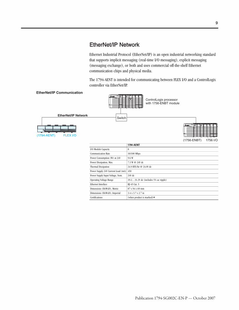
EEtthheerrNNeett//IIPP NNeettwwoorrkk
Ethernet Industrial Protocol (EtherNet/IP) is an open industrial networking standardthat supports implicit messaging (real-time I/O messaging), explicit messaging(messaging exchange), or both and uses commercial off-the-shelf Ethernetcommunication chips and physical media.
The 1794-AENT is intended for communicating between FLEX I/O and a ControlLogixcontroller via EtherNet/IP.
1794-AENTI/O Module Capacity 8
Communication Rate 10/100 Mbps
Power Consumption (W) at 24V 9.6 W
Power Dissipation, Max. 7.3 W @ 24V dc
Thermal Dissipation 24.9 BTU/hr @ 24.0V dc
Power Supply 24V Current Load (mA) 450
Power Supply Input Voltage, Nom. 24V dc
Operating Voltage Range 19.2…31.2V dc (includes 5% ac ripple)
Ethernet Interface RJ-45 Cat. 5
Dimensions (HxWxD), Metric 87 x 94 x 69 mm
Dimensions (HxWxD), Imperial 3.4 x 3.7 x 2.7 in
Certifications (when product is marked)✶

10
Publication 1794-SG002C-EN-P — October 2007
CCoonnttrroollNNeett NNeettwwoorrkk
ControlNet is a real-time control network that provides high-speed transport of bothtime-critical I/O and interlocking data and messaging data, includingupload/download of programming and configuration data on a single physical medialink. The ControlNet network’s highly efficient data transfer capability significantlyenhances I/O performance and peer-to-peer communication in any system orapplication where it is used.
The 1794-ACNR15 adapter is capable of accepting redundant ControlNet cable media.The 1794-ACN15 is a non-redundant version.
The following illustration shows the FLEX I/O platform on a ControlNet network.
1794-ACN15
1794-ACNR15I/O Module Capacity 8
Communication Rate 5 Mbps
Power Consumption (W) at 24V 7.9 W
Inrush Current at 24V 23 A for 2 ms
Power Dissipation, Max. 4.6 W @ 19.2V dc
Thermal Dissipation 15.7 BTU/hr @ 19.2V dc
Power Supply 24V Current Load (mA) 330
Power Supply 24V Output Current, Max. 450 mA
Power Supply Input Voltage, Nom. 24V dc
Operating Voltage Range 19.2…31.2V dc (includes 5% ac ripple)
ControlNet CableAllen-Bradley RG-6/U Quad Shield Coax, Part No. 1786-RG6 (standard-PVC CM-CL2) or1786-RG6F/A (high-flex)
Isolation Voltage Tested at 850V dc for 1 s, user power to system
Dimensions (HxWxD), Metric87 x 94 x 69 mm (1794-ACN15)87 x 94 x 69 mm (1794-ACNR15)
Dimensions (HxWxD), Imperial3.4 x 3.7 x 2.7 in (1794-ACN15)3.4 x 3.7 x 2.7 in (1794-ACNR15)
Certifications
ULCSA Class I Division 2 certifiedGroups A, B, C, D certifiedLCIE Class I Zone 2 Group IIC certifiedCEControlNet

11
Publication 1794-SG002C-EN-P — October 2007
DDeevviicceeNNeett NNeettwwoorrkk
The DeviceNet network is an open low-level network that provides connectionsbetween simple industrial devices (such as sensors and actuators) and higher-leveldevices (such as PLCs and computers). The DeviceNet network uses the provenCommon Industrial Protocol (CIP) to provide the control, configure, and datacollection capabilities for industrial devices. The DeviceNet network is a flexiblenetwork that works with devices from multiple vendors.
The following illustration shows the FLEX I/O platform on a DeviceNet network.
1794-ADNI/O Module Capacity 8
Communication Rate125 Kbps250 Kbps500 Kbps
Power Consumption (W) at 24V 7.9 W
Inrush Current at 24V 23 A for 2 ms
Power Dissipation, Max. 4.6 W @ 19.2V dc
Thermal Dissipation 15.7 BTU/hr @ 19.2V dc
Power Supply 24V Current Load (mA) 330
Power Supply 24V Output Current, Max. 450 mA
Power Supply Input Voltage, Nom. 24V dc
Operating Voltage Range 19.2…31.2V dc (includes 5% ac ripple)
DeviceNet CableAllen-Bradley part no. 1485C-P1-Cxxx. Refer to publication DN-2.5 for more information.Extended Local Cable: 1794-CE1 (0.3 m) or 1794-CE3 (0.9 m)
Isolation Voltage Tested at 850V dc for 1 s, user power to system
Dimensions (HxWxD), Metric 87 x 68 x 69 mm
Dimensions (HxWxD), Imperial 3.4 x 2.7 x 2.7 in
Certifications
ULCSA Class I Division 2 certifiedGroups A, B, C, D certifiedLCIE Class I Zone 2 Group IIC certifiedCEDeviceNet

12
Publication 1794-SG002C-EN-P — October 2007
OOtthheerr CCoommmmuunniiccaattiioonn OOppttiioonnss
Communication adapters and other components are available for adding to yoursystem as your specific application requirements change.
The 1794-FLA is an extended-local adapter for the FlexLogix controller. For moreinformation, refer to the FlexLogix Selection Guide, publication 1794-SG001.
OOtthheerr NNeettwwoorrkkss -- RReemmoottee II//OO
The 1794-ASB and -ASB2 adapters provide connection to the Remote I/O network.The 1794-ASB2 supports only two FLEX I/O modules. The 1794-ASBLT is only for usewith classic PLC 5/15 or PLC 5/25 processors.
DO NOT use these Remote I/O adapters (1794-ASB, Series E; 1794-ASBK, Series E,1794-ASB2, Series D; 1794-ASB2K, Series D) with the Classic PLC-5/15 or PLC-5/25processors. Improper operation of the remote I/O may result.
1794-FLA✶
I/O Module Capacity 8
Power Consumption (W) at 24V 6.5 W(250 mA)
Thermal Dissipation 25.6 BTU/hr @ 19.2V dc
Power Supply Input Voltage, Nom. 24V dc
Operating Voltage Range 19.2…31.2 V dc (includes 5% ac ripple)
Certifications
UL Listed Industrial Control EquipmentCE marked for all applicable directivesCSA Certified Process Control Equipment for Class I, Division 2, Groups A,B,C,D or NonhazardousLocationsC-Tick marked for all applicable acts
✶The 1794-FLA is a bus extender and adapter.

13
Publication 1794-SG002C-EN-P — October 2007
1794-ASB 1794-ASB2 1794-ASBLT✶
I/O Module Capacity 8 2 8
Communication Rate57.6 Kbps115.2 Kbps230.4 Kbps
57.6 Kbps115.2 Kbps230.4 Kbps
57.6 Kbps, 115.2 Kbps, 230.4 KbpsNOTE: PLC5/15 and PLC5/25 can only support 57.6kbps
Power Consumption (W) at 24V 7.9 W 4.2 W 7.9 W
Inrush Current at 24V 23 A for 2 ms 23 A for 2 ms 23 A for 2 ms
Power Dissipation, Max. 4.6 W @ 19.2V dc 3.4 W @ 19.2V dc 4.6 W @ 19.2V dc
Thermal Dissipation 15.7 BTU/hr @ 19.2V dc 11.6 BTU/hr @ 19.2V dc 1.7 BTU/hr @ 31.2V dc max
Power Supply 24V Current Load (mA) 330 175 330
Power Supply Input Voltage, Nom. 24V dc 24V dc 24V dc
Operating Voltage Range 19.2…31.2V dc (includes 5% ac ripple) 19.2…31.2V dc (includes 5% ac ripple) 19.2…31.2V dc (includes 5% ac ripple)
Cable Type
Remote I/O: Belden 9463 or equivalent as specified inA-BApproved Vendor List, publication ICCG-2.2A-B pin connector part no. 942029-03
Remote I/O: Belden 9463 or equivalent as specified inA-B Approved Vendor List, publication ICCG-2.2A-B pin connector part no. 942029-03
Remote I/O: Belden 9463 or equivalent as specified inA-B Approved Vendor List, publication ICCG-2.2A-B pin connector part no. 942029-03
Isolation Voltage Tested at 850V dc for 1 s, user power to system Tested at 850V dc for 1 s, user power to system50V (continuous), Basic Insulation TypeRoutine tested at 850V dc for 1 s, between user powerand system
Dimensions (HxWxD), Metric 87 x 68 x 69 mm 87 x 68 x 69 mm 87 x 69 x 69 mm
Dimensions (HxWxD), Imperial 3.4 x 2.7 x 2.7 in 3.4 x 2.7 x 2.7 in 3.4 x 2.7 x 2.7 in
Certifications
ULCSA Class I Division 2 certifiedGroups A, B, C, D certifiedLCIE Class I Zone 2 Group IIC certifiedC-TickCE
ULCSA Class I Division 2 certifiedGroups A, B, C, D certifiedLCIE Class I Zone 2 Group IIC certifiedC-TickCE
(when product is marked)�
✶ Only for use with Classic PLC 5/15 or PLC 5/25 processors.

14
Publication 1794-SG002C-EN-P — October 2007
Our Encompass partners offer adapters for connecting to RS-232/422/485,Serial/DF1, and Modbus. For details, go to www.rockwellautomation.com/encompassand search for products under the platform FLEX I/O.
OOtthheerr NNeettwwoorrkkss -- PPRROOFFIIBBUUSS DDPP
Use the 1794-APB adapter to connect to an existing PROFIBUS DP network.
1794-APBI/O Module Capacity 8
Communication Rate 57.6 Kbps; 115.2 Kbps; 230.4 Kbps
Power Consumption (W) at 24V 7.9 W
Inrush Current at 24V 23 A for 2 ms
Power Dissipation, Max. 5.3 W @ 19.2V dc
Thermal Dissipation 17.9 BTU/hr @ 19.2V dc
Power Supply 24V Current Load (mA) 450
Power Supply Input Voltage, Nom. 24V dc
Operating Voltage Range 19.2…31.2V dc (includes 5% ac ripple)
PROFIBUS Connector 9-pin D-shell
Cable Type PROFIBUS: Standard drop cable
Isolation Voltage Tested at 850V dc for 1 s, user power to system
Dimensions (HxWxD), Metric 87 x 68 x 69 mm
Dimensions (HxWxD), Imperial 3.4 x 2.7 x 2.7 in
Certifications
UL Listed Industrial Control EquipmentUL Listed for Class I, Division 2 Group A,B,C,D Hazardous LocationsCSA Certified Process Control Equipment for Class I, Division 2 Group A, B, C, DHazardous LocationsCE European Union 89/336/EEC EMC Directive, compliant with: EN 50081-2, IndustrialEmissions; EN 50082-2, Industrial Immunity; EN 61326, Meas./Control/Lab., IndustrialRequirements; 61000-6-2, Industrial ImmunityC-Tick: Australian Radiocommunications Act, compliant with: AS/NZS 2064; IndustrialEmissions✶
✶See the Product Certification link at www.ab.com for Declarations of Conformity, Certificates, and other certification details.
15
Publication 1794-SG002C-EN-P — October 2007
Step 2 - Select:
� I/O modulesSelecting FLEX I/O ModulesThe FLEX I/O module plugs into the terminal base, connecting to the I/O bus and fielddevices. Since there is no direct wiring to the I/O module, you can remove and insertmodules under backplane power, enabling you to change modules without disturbingfield wiring, other I/O modules, or FLEX backplane power. This eliminates costlydowntime and the inefficiencies of restarting a system.
The choices and flexibility you have with I/O types range from digital and analog totemperature and motion control. FLEX I/O allows you to use as many as eight terminalbases per adapter which can provide a maximum of 256 digital I/O points or 96analog channels per adapter. You can mix and match digital and analog I/O withmounting and wiring options, supplying you with a successful distributed systemsolution.
This flexibility gives you the following choices of I/O signal types:
� Digital: ac and dc voltage signals
� Analog: current or voltage
� Relay: normally open, 2 A capability
� Protected outputs: non-latching, latching, and with diagnostics
� Temperature: thermocouple or RTD
� Motion: high-speed counters, flow metering, and totalization
� Combo modules: combination of input and output capability
� Intrinsic Safety (IS): use FLEX Ex I/O in hazardous areas to connect to field devices

16
Publication 1794-SG002C-EN-P — October 2007
DDiiggiittaall II//OO MMoodduulleess Digital I/O modules interface with field devices such as:
- pushbutton and limit switches
- on/off actuators such as motor starters, pilot lights, and annunciators
- relay contacts
Features
� Modules are available in different densities ranging from 8 to 32 points.
� Digital I/O modules cover a wide electrical range:- 120V ac: Input/Output and Isolated Input/Output, 8 and 16 point- 220V ac: Input/Output, 8 point- 24V dc: Input/Output/Combination, Sink/Source, Protected, Electronically Fused,Diagnostic, 8, 16, and 32 point- 48V dc: Sink Input/Source Output, 16 point- Relay: Sink/Source, 8 point
� Isolated inputs and outputs can be used in applications such as motor controlcenters where individual control transformers are used.
� Protected outputs (P) have electronic protection which acts to shut the outputdown in reaction to a short circuit, overload, or over-temperature condition.Recovery from shutdown is automatic upon removal of the output fault. No faultstatus is provided to the processor.
� Electronic Fused (EP) module acts to open the output when a fault occurs. The"fuse" can be reset by operating a pushbutton, via software, or by cycling the inputpower. Fault status is provided to the processor.
� Diagnostic (D) modules detect, indicate, and report to the processor the followingfaults:- open input or output field devices or wiring- shorted output field devices- shorted input or output wiring- reverse polarity of user supply wiring
� Selectable input filter times from <1 to 60 ms.
� LED for each channel indicating status of:- corresponding input device- output signal

17
Publication 1794-SG002C-EN-P — October 2007
Digital I/O Module Summary
Cat. No. Description Number of Inputs Number of Outputs Terminal Base UnitAC Modules
1794-IA8 FLEX I/O 120V ac 8 Input Module 8
⎯
1794-TBN, 1794-TB2, 1794-TB3, 1794-TB3S,1794-TBKD✶.
1794-IA8I FLEX I/O 120V ac 8 Isolated Input Module 81794-TBN, 1794-TB2, 1794-TB3, 1794-TB3S,1794-TBKD�
1794-IA16 FLEX I/O 120V ac 16 Input Module 16 1794-TB3, 1794-TB3S, 1794-TBN�‡
1794-IM8 FLEX I/O 220V ac 8 Input Module 8 1794-TBN�
1794-OA8 FLEX I/O 120V ac 8 Output Module
⎯
81794-TBNF, 1794-TB2, 1794-TB3, 1794-TB3S,1794-TBN, 1794-TBKD�
1794-OA8I FLEX I/O 120V ac 8 Isolated Output Module 81794-TBNF, 1794-TB2, 1794-TB3, 1794-TB3S,1794-TBN, 1794-TBKD�
1794-OA16 FLEX I/O 120V ac 16 Output Module 161794-TB3, 1794-TB2, 1794-TB3S, 1794-TBN,1794-TBKD�§
1794-OM8 FLEX I/O 220V ac 8 Output Module 8 1794-TBNF, 1794-TBN�
DC Modules
1794-IB8 FLEX I/O 24V dc 8 Sink Input Module 8
⎯
1794-TB3, 1794-TB3S�
1794-IB16 FLEX I/O 24V dc 16 Sink Input Module 16 1794-TB3, 1794-TB3S�
1794-IB16D FLEX I/O 24V dc 16 channel digital input module with diagnostics 16 1794-TB32, 1794-TB32S�
1794-IB32 FLEX I/O 24V dc 32 Input Module 32 1794-TB32, 1794-TB32S�
1794-IV16 FLEX I/O 24V dc 16 Source Input Module 16 1794-TB2, 1794-TB3, 1794-TB3S, 1794-TBKD�
1794-IB10XOB6 FLEX I/O 24V dc 10 Input/6 2 A Output Combo Module 10 6 1794-TB3, 1794-TB3S�
1794-IB16XOB16P FLEX I/O 24V dc 16 Input/16 Protected Output Module 16 16 1794-TB32, TB32S�
1794-IC16 FLEX I/O 48V dc 16 Sink Input Module 16 ⎯ 1794-TB3, 1794-TB3S�
1794-OB8 FLEX I/O 24V dc 8 Source Output Module
⎯
8 1794-TB2, 1794-TB3, 1794-TB3S, 1794-TBKD�
1794-OB8EP FLEX I/O 24V dc Electronically Protected 8 Output Module 81794-TB3, 1794-TB2, 1794-TB3S, 1794-TBN,1794-TBKD�
1794-OB16 FLEX I/O 24V dc 16 Source Output Module 16 1794-TB2, 1794-TB3, 1794-TB3S, 1794-TBKD�
1794-OB16D FLEX I/O 24V dc 16 channel digital output module with diagnostics 16 1794-TB3, 1794-TB3S, 1794-TBKD�
1794-OB16P FLEX I/O 24V dc 16 Protected Source Output Module 16 1794-TB2, 1794-TB3, 1794-TB3S, 1794-TBKD�
1794-OB32P FLEX I/O 24V dc 32 Protected Source Output Module 32 1794-TB32, 1794-TB32S�
1794-OV16 FLEX I/O 24V dc 16 Sink Output Module 16 1794-TB3, 1794-TB3S�
1794-OV16P FLEX I/O 24V dc 16 Protected Sink Output Module 16 1794-TB3, 1794-TB3S�
1794-OC16 FLEX I/O 48V dc 16 Source Output Module 16 1794-TB3, 1794-TB2, 1794-TB3S, 1794-TBKD�
Relay Modules
1794-OW8 FLEX I/O 24V dc 8 Relay Sink/Source Output Module 81794-TBNF, 1794-TBN, 1794-TB2, 1794-TB3,1794-TB3S, 1794-TBKD�
✶Recommended terminal base is in bold text�Recommended terminal base is in bold text.‡Auxiliary terminal strips are required when using the 1794-TBN for the 1794-IA16 and 1794-IA16.§Auxiliary terminal strips are required when using the 1794-TBN for the 1794-OA16 and 1794-IA16.

18
Publication 1794-SG002C-EN-P — October 2007
Conformal coated versions of standard modules have the letter K in the last position ofthe catalog number, before the series designation.
Conformal Coated Description
1794-IA8KANSI / ISA-S71.04-1985, Class G1, G2, and G3 environmentsCEI IEC 6065A-4 Class 1 and 2 environmentsUL 746E
1794-IB16K
1794-OA8K
1794-OB16PK
1794-OB8EPKANSI / ISA-S71.04-1985, Class G1, G2, and G3 environmentsCEI IEC 6065A-4 Class 1 and 2 environmentsUL 746E
1794-ACN15 —
1794-ACNR15 —
1794-ADN —
1794-ASB —
1794-IE8 —
1794-IB16 —
1794-IRT8 —
1794-OB16 —
1794-OE4 —
1794-OW8 —
1794-TB3 —
1794-TB3G —
1794-TBN —
1794-IA8 —
1794-OA8 —
1794-OB8EP —
1794-IJ2 —
Input Filter Times - AC Modules
Filter Times forInputs
Maximum Times (ms)
OFF to ON ON to OFF
1794-IA8, -IA8I 1794-IA16, -IM8 1794-IA8, -IA8I 1794-IA16, -IM8
Filter Time 0 (default) 8.4✶ 7.5 26.4� 26.5
1 8.6 8 26.6 27
2 9 9 27 28
3 10 10 28 29
4 12 12 30 31
5 16 16 34 35
6 24 24.5 42 44
7 40 42 58 60.5
✶OFF to ON filter is 8 ms.�ON to OFF filter is 26 ms.

19
Publication 1794-SG002C-EN-P — October 2007
SSeelleeccttiinngg IInnppuutt FFiilltteerr TTiimmeess ffoorr DDiiggiittaall MMoodduulleess
Input filter times can be set to the following values (EtherNet I/P, ControlNet, andDeviceNet only):
Input Filter Times - DC Modules
Filter Times forInputs
Maximum Times (ms)
OFF to ON and ON to OFF
1794-IB8, -IB16, -IB32, -IV16, -IC16, -IB10XOB6, -IB16XOB16PFilter Time 0 (default) 0.25
1 0.5
2 1
3 2
4 4
5 8
6 16
7 32
Input Filter Times - AC Modules
Filter Times forInputs
Maximum Times (ms)
OFF to ON ON to OFF
1794-IA8, -IA8I 1794-IA16, -IM8 1794-IA8, -IA8I 1794-IA16, -IM8
Filter Time 0 (default) 8.4✶ 7.5 26.4� 26.5
1 8.6 8 26.6 27
2 9 9 27 28
3 10 10 28 29
4 12 12 30 31
5 16 16 34 35
6 24 24.5 42 44
7 40 42 58 60.5
✶OFF to ON filter is 8 ms.�ON to OFF filter is 26 ms.

20
Publication 1794-SG002C-EN-P — October 2007
FFLLEEXX II//OO DDiiggiittaall AACCIInnppuutt MMoodduulleess
1794-IA8 accepts 8 inputs from 120V ac field input devices that can have off-stateleakage as high as 2.5 mA. For noisy input signals, all input modules can beprogrammed with filter times from 10...60 ms.
1794-IA8I provides 8 isolated inputs with the same specifications as the 1794-IA8.
1794-IA16 is the 16 input version of the 1794-IA8.
1794-IM8 is the 220V ac version of the 1794-IA8.
1794-IA8 1794-IA8I 1794-IA16 1794-IM8Voltage, On-State Input, Nom. 120V ac 120V ac, isolated 120V ac 220V ac
Terminal Base Unit1794-TBN, 1794-TB2, 1794-TB3, 1794-TB3S, 1794-TBKD✶.
1794-TBN, 1794-TB2, 1794-TB3, 1794-TB3S, 1794-TBKD� 1794-TB3, 1794-TB3S, 1794-TBN�§ 1794-TBN�
Current, On-State Input, Nom. 12 mA @ 120V ac, 60 Hz 12 mA @ 120V ac, 60 Hz 12 mA @ 120V ac, 60 Hz 10 mA @ 220V ac, 60 Hz
Input Impedance, Nom. 10.6 kΩ 10.6 kΩ 10 kΩ 22.3 kΩ
Voltage, On-State Input, Min. 65V ac 65V ac 74V ac 159V ac
Voltage, Off-State Input, Max. 43V ac 43V ac 20V ac 40V ac
Current, On-State Input, Min.‡ 7.1 mA♣➤��� 7.1 mA♣➤��� 5.5 mA @ 74V ac, 47 Hz♣➤��� 5.3 mA @ 159V ac, 47 Hz♣➤���
Current, Off-State Input, Max. 2.9 mA 2.9 mA 2.9 mA 2.6 mA
Power Dissipation, Max. 4.5 W @ 132V ac 4.5 W @ 132V ac 6.4 W @ 132V ac 4.7 W @ 264V ac
Thermal Dissipation, Max. 15.3 BTU/hr @ 132V ac 15.3 BTU/hr @ 132V ac 21.8 BTU/hr @ 132V ac 16.2 BTU/hr @ 264V ac
Dimensions (HxWxD), Metric 46 x 94 x 53 mm 46 x 94 x 53 mm 46 x 94 x 53 mm 46 x 94 x 53 mm
Dimensions (HxWxD), Imperial 1.8 x 3.7 x 2.1 in 1.8 x 3.7 x 2.1 in 1.8 x 3.7 x 2.1 in 1.8 x 3.7 x 2.1 in
Isolation Voltage
120V continuousTested to 2150V dc for 1 s and 1250V acfor 60 s, I/O to system(No isloation between individualchannels)
120V continuousTested to 2150V dc for 1 s and 1250V acfor 60 s, I/O to systemand I/O to I/O
120V continuousTested to 2150V dc for 1 s and 1250V acfor 60 s, I/O to system(No isloation between individualchannels)
Tested at 2600V dc for 1 s, I/O to system(No isolation between individualchannels)
✶Recommended terminal base is in bold text�Recommended terminal base is in bold text.§Auxiliary terminal strips are required when using the 1794-TBN for the 1794-IA16 and 1794-IA16.♣AC inputs compatible with proximity switches with leakage ratings of I➤leak� < 2.5 mA and I�on� min = 5 mA.
1794-IM8 Derating Curve

21
Publication 1794-SG002C-EN-P — October 2007
FFLLEEXX II//OO DDiiggiittaall AACCOOuuttppuutt MMoodduulleess
1794-OA8 provides 8 120V ac 1/2 Amp outputs that can be used up to 1 Amp withlimitations.
1794-OA8I is the isolated version of the 1794-OA8.
1794-OA16 provides 16 1/4 Amp outputs with specified limitations when used at 1/2Amp.
1794-OM8 provides 8 220V ac outputs rated at 1/2 Amp each.
These modules are not fused. External channel fusing or use of fused terminal bases(TBNF) is required with the - point modules.
1794-OA8 1794-OA8I 1794-OA16 1794-OM8Voltage, On-State Output, Nom. 120V ac 120V ac, isolated 120V ac 220V ac
Terminal Base Unit✶1794-TBNF, 1794-TB2, 1794-TB3,1794-TB3S, 1794-TBN, 1794-TBKD
1794-TBNF, 1794-TB2, 1794-TB3,1794-TB3S, 1794-TBN, 1794-TBKD
1794-TB3, 1794-TB2, 1794-TB3S,1794-TBN, 1794-TBKD�
1794-TBNF, 1794-TBN
Current, On-State Output, Min. 5 mA per output 5 mA per output 5 mA per output 5 mA per output
Current, On-State Output, Max.
500 mA per output @ 55 °C (sufficientto operate an A-B Bulletin 500 NEMAsize 3 motor starter)750 mA per output @ 35 °C1.0 A on 4 nonadjacent outputs and500 mA on the remaining 4 outputs @30 °C
500 mA per output @ 55 °C (sufficientto operate an A-B Bulletin 500 NEMAsize 3 motor starter)750 mA per output @ 35 °C1.0A on 4 nonadjacent outputs and 500mA on the remaining 4 outputs @ 30°C
500 mA per output @ 55 °C‡♣ 500 mA @ 55 °C�
Current, On-State Output, per Module 4.0 A (8 outputs @ 500 mA) 4.0 A (8 outputs @ 500 mA) 4.0 A (16 outputs @ 250 mA) 4.0 A (8 outputs @ 500 mA)�
Leakage Current, Off-State Output, Max 2.25 mA 2.25 mA 2.25 mA 2.5 mA
Voltage Drop, On-State Output, Max. 1.0V @ 0.5 A 1.0V @ 0.5 A 1.5V @ 0.5 A 1.5 V @ 0.5 A
Output Surge Current, Max. 7 A for 45 ms, repeatable every 8 s 7 A for 45 ms, repeatable every 8 s 7 A for 40 ms, repeatable every 8 s 7 A for 40 ms, repeatable every 8 s
Voltage, On-State Output, Min.� 85V ac 85V ac 85V ac 159V ac
Voltage, On-State Output, Nom.� 120V ac 120V ac 120V ac 220V ac
Voltage, On-State Output, Max.� 132V ac 132V ac 132V ac 264V ac
Power Dissipation, Max.4.1 W @ 0.5 A6.3 W @ 0.75 A6.3 W @ 1.0 A
4.1 W @ 0.5 A6.3 W @ 0.75 A6.3 W @ 1.0 A
4.7 W @ 0.5 A 5 W @ 0.5 A
Thermal Dissipation14.0 BTU/hr @ 0.5 A21.1 BTU/hr @ 0.75 A21.4 BTU/hr @ 1.0 A
14.0 BTU/hr @ 0.5 A21.1 BTU/hr @ 0.75 A21.4 BTU/hr @ 1.0 A
16.1 BTU/hr @ 0.5 A 17.1 BTU/hr @ 0.5 A
Dimensions (HxWxD), Metric 46 x 94 x 53 mm 46 x 94 x 53 mm 46 x 94 x 53 mm 46 x 94 x 53 mm
Dimensions (HxWxD), Imperial 1.8 x 3.7 x 2.1 in 1.8 x 3.7 x 2.1 in 1.8 x 3.7 x 2.1 in 1.8 x 3.7 x 2.1 in
Isolation Voltage
120V continuousTested to 2150V dc for 1 s and 1250Vac for 60 s, I/O to system(No isolation between individualchannels)
120V continuousTested to 2150V dc for 1 s and 1250Vac for 60 s, channel to channel, I/O tosystem
120V continuousTested to 2150V dc for 1 s and 1250Vac for 60 s, I/O to system(No isolation between individualchannels)
Tested at 2600V dc for 1 s, I/O tosystem(No isolation between individualchannels)
✶Recommended terminal base is in bold text.�Auxiliary terminal strips are required when using the 1794-TBN for the 1794-OA16 and 1794-IA16.‡If using 0.5 A outputs, alternate wiring so that no two 0.5 A outputs are adjacent. See the 1794-OA16 derating curve for mounting other than normal horizonal.�See the 1794-OM8 derating curve.§Below 50 mA the voltage drop across the module will be higher and the voltage waveform may have some small oscillation (less than 5V).♣If using 0.5 A outputs, alternate wiring so that no two 0.5 A outputs are adjacent. See the 1794-OA16 derating curve for mounting other than normal horizontal.➤See the 1794-OM8 derating curve.�1794-OA8I also tested for isolation between channels.�The external ac supply voltage must be capable of a 50 A surge for 1/2 cycle at power-up.NNoottee:: The output signal delay, OFF to ON or ON to OFF is 1/2 cycle maximum.Modules have a yellow status indicator for each channel. These indicators are driven from the logic-side circuitry.Module outputs are not fused. Fusing of individual outputs is required. If applicable, the 1794-TBNF is recommended, otherwise you must provide external fusing. The following fuses are
recommended:� 1794-OA8, -OA8I - Use 1.6 A, 250V Slow-Blow, Littelfuse pt. no. 23901.6; San-o SD6-1.6 A; AB pt. no. 94171304. The 1794-TBNF comes with SD6-1.6 A fuses installed.� 1794-OA16 - Use 2.5 A, 150V MQ2 normal fuse.� 1794-OM8 - Use 0.8 A, 250V MQ4 normal fuse.

22
Publication 1794-SG002C-EN-P — October 2007
FFLLEEXX II//OO DDiiggiittaall AACCOOuuttppuutt MMoodduulleess
1794-OA8 provides 8 120V ac 1/2 Amp outputs that can be used up to 1 Amp withlimitations.
1794-OA8I is the isolated version of the 1794-OA8.
1794-OA16 provides 16 1/4 Amp outputs with specified limitations when used at 1/2Amp.
1794-OM8 provides 8 220V ac outputs rated at 1/2 Amp each.
These modules are not fused. External channel fusing or use of fused terminal bases(TBNF) is required with the - point modules.
1794-OA8 1794-OA8I 1794-OA16 1794-OM8Voltage, On-State Output, Nom. 120V ac 120V ac, isolated 120V ac 220V ac
Terminal Base Unit✶1794-TBNF, 1794-TB2, 1794-TB3,1794-TB3S, 1794-TBN, 1794-TBKD
1794-TBNF, 1794-TB2, 1794-TB3,1794-TB3S, 1794-TBN, 1794-TBKD
1794-TB3, 1794-TB2, 1794-TB3S,1794-TBN, 1794-TBKD�
1794-TBNF, 1794-TBN
Current, On-State Output, Min. 5 mA per output 5 mA per output 5 mA per output 5 mA per output
Current, On-State Output, Max.
500 mA per output @ 55 °C (sufficientto operate an A-B Bulletin 500 NEMAsize 3 motor starter)750 mA per output @ 35 °C1.0 A on 4 nonadjacent outputs and500 mA on the remaining 4 outputs @30 °C
500 mA per output @ 55 °C (sufficientto operate an A-B Bulletin 500 NEMAsize 3 motor starter)750 mA per output @ 35 °C1.0A on 4 nonadjacent outputs and 500mA on the remaining 4 outputs @ 30°C
500 mA per output @ 55 °C‡♣ 500 mA @ 55 °C�
Current, On-State Output, per Module 4.0 A (8 outputs @ 500 mA) 4.0 A (8 outputs @ 500 mA) 4.0 A (16 outputs @ 250 mA) 4.0 A (8 outputs @ 500 mA)�
Leakage Current, Off-State Output, Max 2.25 mA 2.25 mA 2.25 mA 2.5 mA
Voltage Drop, On-State Output, Max. 1.0V @ 0.5 A 1.0V @ 0.5 A 1.5V @ 0.5 A 1.5 V @ 0.5 A
Output Surge Current, Max. 7 A for 45 ms, repeatable every 8 s 7 A for 45 ms, repeatable every 8 s 7 A for 40 ms, repeatable every 8 s 7 A for 40 ms, repeatable every 8 s
Voltage, On-State Output, Min.� 85V ac 85V ac 85V ac 159V ac
Voltage, On-State Output, Nom.� 120V ac 120V ac 120V ac 220V ac
Voltage, On-State Output, Max.� 132V ac 132V ac 132V ac 264V ac
Power Dissipation, Max.4.1 W @ 0.5 A6.3 W @ 0.75 A6.3 W @ 1.0 A
4.1 W @ 0.5 A6.3 W @ 0.75 A6.3 W @ 1.0 A
4.7 W @ 0.5 A 5 W @ 0.5 A
Thermal Dissipation14.0 BTU/hr @ 0.5 A21.1 BTU/hr @ 0.75 A21.4 BTU/hr @ 1.0 A
14.0 BTU/hr @ 0.5 A21.1 BTU/hr @ 0.75 A21.4 BTU/hr @ 1.0 A
16.1 BTU/hr @ 0.5 A 17.1 BTU/hr @ 0.5 A
Dimensions (HxWxD), Metric 46 x 94 x 53 mm 46 x 94 x 53 mm 46 x 94 x 53 mm 46 x 94 x 53 mm
Dimensions (HxWxD), Imperial 1.8 x 3.7 x 2.1 in 1.8 x 3.7 x 2.1 in 1.8 x 3.7 x 2.1 in 1.8 x 3.7 x 2.1 in
Isolation Voltage
120V continuousTested to 2150V dc for 1 s and 1250Vac for 60 s, I/O to system(No isolation between individualchannels)
120V continuousTested to 2150V dc for 1 s and 1250Vac for 60 s, channel to channel, I/O tosystem
120V continuousTested to 2150V dc for 1 s and 1250Vac for 60 s, I/O to system(No isolation between individualchannels)
Tested at 2600V dc for 1 s, I/O tosystem(No isolation between individualchannels)
✶Recommended terminal base is in bold text.�Auxiliary terminal strips are required when using the 1794-TBN for the 1794-OA16 and 1794-IA16.‡If using 0.5 A outputs, alternate wiring so that no two 0.5 A outputs are adjacent. See the 1794-OA16 derating curve for mounting other than normal horizonal.�See the 1794-OM8 derating curve.§Below 50 mA the voltage drop across the module will be higher and the voltage waveform may have some small oscillation (less than 5V).♣If using 0.5 A outputs, alternate wiring so that no two 0.5 A outputs are adjacent. See the 1794-OA16 derating curve for mounting other than normal horizontal.➤See the 1794-OM8 derating curve.�1794-OA8I also tested for isolation between channels.�The external ac supply voltage must be capable of a 50 A surge for 1/2 cycle at power-up.NNoottee:: The output signal delay, OFF to ON or ON to OFF is 1/2 cycle maximum.Modules have a yellow status indicator for each channel. These indicators are driven from the logic-side circuitry.Module outputs are not fused. Fusing of individual outputs is required. If applicable, the 1794-TBNF is recommended, otherwise you must provide external fusing. The following fuses are
recommended:� 1794-OA8, -OA8I - Use 1.6 A, 250V Slow-Blow, Littelfuse pt. no. 23901.6; San-o SD6-1.6 A; AB pt. no. 94171304. The 1794-TBNF comes with SD6-1.6 A fuses installed.� 1794-OA16 - Use 2.5 A, 150V MQ2 normal fuse.� 1794-OM8 - Use 0.8 A, 250V MQ4 normal fuse.

23
Publication 1794-SG002C-EN-P — October 2007
1794-OA16 Derating Curve
1794-OM8 Derating Curve

24
Publication 1794-SG002C-EN-P — October 2007
FFLLEEXX II//OO DDiiggiittaall DDCCIInnppuutt MMoodduulleess
1794-IB8 & 1794-IB16 1794-IB32 1794-IV16 1794-IC16Voltage, On-State Input, Min. 10V dc, sinking 19.2V dc, sinking 10V dc, sourcing 30V dc, sinking
Voltage, On-State Input, Nom. 24V dc 24V dc 24V dc 48V dc
Voltage, On-State Input, Max. 31.2V dc 31.2V dc 31.2V dc 60V dc
Terminal Base Unit 1794-TB3, 1794-TB3S✶ 1794-TB32, 1794-TB32S✶1794-TB2, 1794-TB3, 1794-TB3S,1794-TBKD✶
1794-TB3, 1794-TB3S✶
Current, On-State Input, Nom. 8 mA @ 24V dc 4.1 mA @ 24V dc 8 mA @ 24V dc 5.0 mA at 48V dc
Current, On-State Input, Max. 11 mA 6.0 mA 11 mA 11.0 mA
Input Impedance, Max. 4.6 kΩ 6.0 kΩ 4.7 kΩ 11 kΩ
Voltage, On-State Input, Min. 10V dc 19.2V dc 10V dc 30V dc
Voltage, Off-State Input, Max. 5.0V dc 5.0V dc 5.0V dc 10.0V dc
Current, On-State Input, Min. 2.0 mA 2.0 mA 2.0 mA 2.0 mA
Current, Off-State Input, Max. 1.5 mA 1.5 mA 1.5 mA 1.5 mA
Power Dissipation, Max. 3.1 W @ 31.2V dc� 6.0 W @ 31.2V dc 5.7 W @ 31.2V dc 6.4 W @ 60V dc
Thermal Dissipation, Max. 11.9 BTU/hr @ 31.2V dc‡ 20.5 BTU/hr @ 31.2V dc 19.4 BTU/hr @ 31.2V dc 21.9 BTU/hr @ 60V dc
Dimensions (HxWxD), Metric 46 x 94 x 53 mm‡ 45.7 x 94.0 x 53.3 mm 46 x 94 x 53 mm 46 x 94 x 53 mm
Dimensions (HxWxD), Imperial 1.8 x 3.7 x 2.1 in‡ 1.8 x 3.7 x 2.1 in 1.8 x 3.7 x 2.1 in 1.8 x 3.7 x 2.1 in
Isolation VoltageTested at 850V dc for 1 s, I/O to system(No isolation between individualchannels)
Tested at 2121V dc for 1 s, I/O to system(No isolation between individualchannels)
Tested at 2121V dc for 1 s, I/O to system(No isolation between individualchannels)
Tested at 1900V dc for 1 s, I/O to system(No isolation between individualchannels)
✶Recommended terminal base is in bold text.�6.1 W @ 31.2V dc for 1794-IB16.‡20.8 BTU/hr @ 31.2V dc for 1794-IB16.NNoottee:: Do not put the 1794-IB8 module next to an output module in 8-point compact addressing with the 1794-ASB2/C or -ASB/D.Modules have a yellow status indicator for each channel. These indicators are driven from the customer field-side input device.
1794-IB16 Derating Curve

25
Publication 1794-SG002C-EN-P — October 2007
1794-IB16D Derating Curve

26
Publication 1794-SG002C-EN-P — October 2007
1794-IB32 Derating Curve
1794-IC16 Derating Curve
27
Publication 1794-SG002C-EN-P — October 2007
FFLLEEXX II//OO DDiiggiittaall DDCCOOuuttppuutt MMoodduulleess
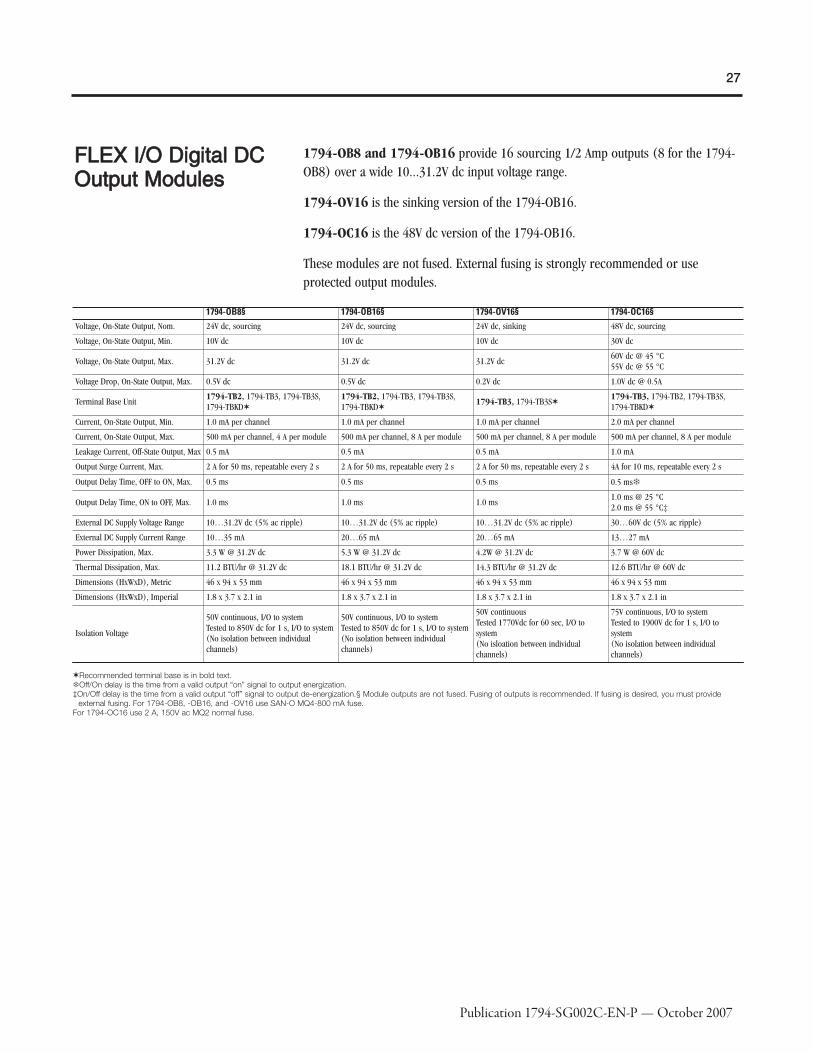
1794-OB8 and 1794-OB16 provide 16 sourcing 1/2 Amp outputs (8 for the 1794-OB8) over a wide 10...31.2V dc input voltage range.
1794-OV16 is the sinking version of the 1794-OB16.
1794-OC16 is the 48V dc version of the 1794-OB16.
These modules are not fused. External fusing is strongly recommended or useprotected output modules.
1794-OB8§ 1794-OB16§ 1794-OV16§ 1794-OC16§Voltage, On-State Output, Nom. 24V dc, sourcing 24V dc, sourcing 24V dc, sinking 48V dc, sourcing
Voltage, On-State Output, Min. 10V dc 10V dc 10V dc 30V dc
Voltage, On-State Output, Max. 31.2V dc 31.2V dc 31.2V dc60V dc @ 45 °C55V dc @ 55 °C
Voltage Drop, On-State Output, Max. 0.5V dc 0.5V dc 0.2V dc 1.0V dc @ 0.5A
Terminal Base Unit1794-TB2, 1794-TB3, 1794-TB3S,1794-TBKD✶
1794-TB2, 1794-TB3, 1794-TB3S,1794-TBKD✶
1794-TB3, 1794-TB3S✶1794-TB3, 1794-TB2, 1794-TB3S,1794-TBKD✶
Current, On-State Output, Min. 1.0 mA per channel 1.0 mA per channel 1.0 mA per channel 2.0 mA per channel
Current, On-State Output, Max. 500 mA per channel, 4 A per module 500 mA per channel, 8 A per module 500 mA per channel, 8 A per module 500 mA per channel, 8 A per module
Leakage Current, Off-State Output, Max 0.5 mA 0.5 mA 0.5 mA 1.0 mA
Output Surge Current, Max. 2 A for 50 ms, repeatable every 2 s 2 A for 50 ms, repeatable every 2 s 2 A for 50 ms, repeatable every 2 s 4A for 10 ms, repeatable every 2 s
Output Delay Time, OFF to ON, Max. 0.5 ms 0.5 ms 0.5 ms 0.5 ms�
Output Delay Time, ON to OFF, Max. 1.0 ms 1.0 ms 1.0 ms1.0 ms @ 25 °C2.0 ms @ 55 °C‡
External DC Supply Voltage Range 10…31.2V dc (5% ac ripple) 10…31.2V dc (5% ac ripple) 10…31.2V dc (5% ac ripple) 30…60V dc (5% ac ripple)
External DC Supply Current Range 10…35 mA 20…65 mA 20…65 mA 13…27 mA
Power Dissipation, Max. 3.3 W @ 31.2V dc 5.3 W @ 31.2V dc 4.2W @ 31.2V dc 3.7 W @ 60V dc
Thermal Dissipation, Max. 11.2 BTU/hr @ 31.2V dc 18.1 BTU/hr @ 31.2V dc 14.3 BTU/hr @ 31.2V dc 12.6 BTU/hr @ 60V dc
Dimensions (HxWxD), Metric 46 x 94 x 53 mm 46 x 94 x 53 mm 46 x 94 x 53 mm 46 x 94 x 53 mm
Dimensions (HxWxD), Imperial 1.8 x 3.7 x 2.1 in 1.8 x 3.7 x 2.1 in 1.8 x 3.7 x 2.1 in 1.8 x 3.7 x 2.1 in
Isolation Voltage
50V continuous, I/O to systemTested to 850V dc for 1 s, I/O to system(No isolation between individualchannels)
50V continuous, I/O to systemTested to 850V dc for 1 s, I/O to system(No isolation between individualchannels)
50V continuousTested 1770Vdc for 60 sec, I/O tosystem(No isloation between individualchannels)
75V continuous, I/O to systemTested to 1900V dc for 1 s, I/O tosystem(No isolation between individualchannels)
✶Recommended terminal base is in bold text.�Off/On delay is the time from a valid output “on” signal to output energization.‡On/Off delay is the time from a valid output “off” signal to output de-energization.§ Module outputs are not fused. Fusing of outputs is recommended. If fusing is desired, you must provide
external fusing. For 1794-OB8, -OB16, and -OV16 use SAN-O MQ4-800 mA fuse.For 1794-OC16 use 2 A, 150V ac MQ2 normal fuse.

28
Publication 1794-SG002C-EN-P — October 2007
DDiiggiittaall DDCC PPrrootteecctteeddOOuuttppuutt MMoodduulleess
1794-OB16P provides 16 sourcing 1/2 Amp outputs self-protected against shorts,overloads, and over temperature. The faulted output will automatically return when thefault is removed. No feedback to the processor is provided.
1794-OB8EP provides 8 sourcing 2 Amp outputs with electronic fuse type of overloadprotection, which opens when overloaded. The fuse can be 'reset' several ways. Faultstatus is provided to the processor.
1794-OB32P provides 32 self-protected sourcing 1/2 Amp outputs in 2 groups of 16outputs. Separate voltage sources can be used with each group.
1794-OV16P is the sinking version of the 1794-OB16P.
1794-OB16P 1794-OB8EP 1794-OB32P 1794-OV16PVoltage, On-State Output, Nom. 24V dc, sourcing 24V dc, sourcing 24V dc, sourcing 24V dc, sinking
Voltage, On-State Output, Min. 10V dc 19.2V dc 10V dc 10V dc
Voltage, On-State Output, Max. 31.2V dc✶ 31.2V dc 31.2V dc 31.2V dc
Voltage Drop, On-State Output, Max. 0.5V dc 0.2V dc 0.5V dc 0.2V dc
Terminal Base Unit1794-TB2, 1794-TB3, 1794-TB3S,1794-TBKD�
1794-TB3, 1794-TB2, 1794-TB3S,1794-TBN, 1794-TBKD� 1794-TB32, 1794-TB32S� 1794-TB3, 1794-TB3S�
Current, On-State Output, Min.§ 1.0 mA per channel 1.0 mA per channel 1.0 mA per channel 1.0 mA per channel
Current, On-State Output, Max. 500 mA per channel, 8 A per module 2.0 A per channel, 10 A per module500 mA per channel;14 A per module (6 A total for channels0…15; 8 A total for channels 16…31)
500 mA per channel, 8 A per module
Leakage Current, Off-State Output, Max 0.5 mA 0.5 mA 0.5 mA 0.5 mA
Output Surge Current, Max. 1.5 A for 50 ms, repeatable every 2 s 4 A for 10 ms, repeatable every 3 s‡ 2 A for 50 ms, repeatable every 2 s 2 A for 50 ms, repeatable every 2 s
External DC Supply Voltage Range 10…31.2V dc (5% ac ripple) 19.2…31.2V dc (5% ac ripple) 10…31.2V dc (5% ac ripple) 10…31.2V dc (5% ac ripple)
External DC Supply Current Range 25…75 mA 20…35 mA 103…273 mA 20…65 mA
Power Dissipation, Max. 5.0 W @ 31.2V dc 5.5 W @ 31.2V dc 5.3 W @ 31.2V dc 4.2 W @ 31.2V dc
Thermal Dissipation, Max. 17.0 BTU/hr @ 31.2V dc 18.8 BTU/hr @ 31.2V dc 18.1 BTU/hr @ 31.2V dc 14.3 BTU/hr @ 31.2V dc
Dimensions (HxWxD), Metric 46 x 94 x 53 mm 46 x 94 x 53 mm 45.7 x 94.0 x 53.3 mm 46 x 94 x 53 mm
Dimensions (HxWxD), Imperial 1.8 x 3.7 x 2.1 in 1.8 x 3.7 x 2.1 in 1.8 x 3.7 x 2.1 in 1.8 x 3.7 x 2.1 in
Isolation Voltage
50V (continuous), Basic InsulationTypeType tested at 2121V dc for 60 s,between field side and systemNo isolation between individualchannels
50V continuous, I/O to systemTested to 850V dc for 1 s, I/O to system(No isolation between individualchannels)
50V continuous, I/O to systemTested to 2150V ac for 1 s, I/O tosystem(No isolation between individualchannels)
50V continuousTested 1770Vdc for 60 sec, I/O tosystem(No isloation between individualchannels)
✶See 1794-OB16P Derating Curve�Recommended terminal base is in bold text.‡See 1794-OB8EP Output Minimum Surge chart.

29
Publication 1794-SG002C-EN-P — October 2007
1794-OB16P Derating Curve
1794-OB8EP Output Minimum Surge

30
Publication 1794-SG002C-EN-P — October 2007
FFLLEEXX II//OO DDiiggiittaall DDCCDDiiaaggnnoossttiicc MMoodduulleess
1794-IB16D is the diagnostic version of the 1794-IB16.
1794-OB16D is the diagnostic version of the 1794-OB16.
The modules can detect open wire, short circuit, and reverse polarity of externalpower. When a fault is detected, the module turns on the module fault LED, thecorresponding channel's red LED, and sets the corresponding module error bit (openwire, short circuit, or reverse power bit). The reporting function provides the resultsof the diagnostics as bits in the data table.
The modules can detect open wire, short-circuit, and reverse polarity of externalpower. When a fault is detected, the module turns on the module fault LED, thecorresponding channel's red LED, and sets the module error open wire, short-circuit,or reverse power error bit. The reporting function provides the results of thediagnostics as bits in its data table.
The modules have 16 bi-color channel status indicators and one red module statusindicator. These indicators are driven from the customer field side power.
1794-IB16DVoltage, On-State Input, Min. 10V dc, sinking
Voltage, On-State Input, Nom. 24V dc
Voltage, On-State Input, Max. 31.2V dc✶
Voltage, Off-State Input, Max. 5.0V dc
Current, On-State Input, Nom. 8.2 mA at 24V dc
Current, On-State Input, Max. 12.1 mA @ 31.2V dc
Current, On-State Input, Max. 12.1 mA @ 31.2V dc
Terminal Base Unit 1794-TB32, 1794-TB32S�
Input Impedance, Max. 3.1 kΩ
Current, On-State Input, Min. 2.0 mA at 10 dc
Current, Off-State Input, Max. 1.5 mA
Power Dissipation, Max. 8.5 W @ 31.2V dc
Thermal Dissipation, Max. 29 BTU/hr @ 31.2V dc
Detect Reverse Polarity Voltage =2,5100
Sensor Voltage Drop 2.2V dc max
Current, Sensor Source, Max. 50 mA max
Dimensions (HxWxD), Imperial =4,1070043
Dimensions (HxWxD), Imperial 1.8 x 3.7 x 2.1 in
Isolation VoltageTested at 2121V dc for 1 s, I/O to system(No isolation between individual channels)
✶See 1794-IB16D Input Voltage Derating chart.�Recommended terminal base is in bold text.

31
Publication 1794-SG002C-EN-P — October 2007
1794-OB16DVoltage, On-State Output, Min. 10V dc, sourcing
Voltage, On-State Output, Max. 31.2V dc
Voltage Drop, On-State Output, Max. 0.5V dc @ 0.5 A
Terminal Base Unit 1794-TB3, 1794-TB3S, 1794-TBKD✶
Current, On-State Output, Min.§ 2.0 mA per channel
Current, On-State Output, Max.500 mA per channel8 A per module
Leakage Current, Off-State Output, Max 0.5 mA
Output Surge Current, Max. 2 A for 50 ms, repeatable every 2 s
External DC Supply Voltage Range 10…31.2V dc (5% ac ripple)
External DC Supply Current Range 56…78 mA
Power Dissipation, Max. 4.8 W @ 31.2V dc
Thermal Dissipation, Max. 16.4 BTU/hr @ 31.2V dc
Short Circuit ProtectionThermal shutdown (auto reset)Detection condition: when external power active, output signal active, and output portvoltage less than 2V
Short Circuit ProtectionThermal shutdown (auto reset)Detection condition: when external power active, output signal active, and output portvoltage less than 2V
Open Wire Detect, Off-State Leakage Current 0.1 mA - When external power active and output signal inactive
Detect Reverse Polarity Voltage10V min.: Module must detect if the reverse polarity external power supply voltage isgreater than the value
Current, Sensor Source, Max. Yes
Dimensions (HxWxD), Metric =2,1070042
Dimensions (HxWxD), Metric 45.7 x 94.0 x 53.3 mm
Dimensions (HxWxD), Imperial 1.8 x 3.7 x 2.1 in
Isolation Voltage50V continuous, I/O to systemTested to 2121V dc for 1 s, I/O to system(No isolation between individual channels)
✶Recommended terminal base is in bold text.

32
Publication 1794-SG002C-EN-P — October 2007
DDeerraattiinngg CCuurrvveess11779944--IIBB1166DD IInnppuuttVVoollttaaggee

33
Publication 1794-SG002C-EN-P — October 2007
FFLLEEXX II//OO DDiiggiittaall DDCCCCoommbbiinnaattiioonnMMoodduulleess
The 1794-IB16XOB16P has ouptputs that are self-protected against shorts, overloads,and over temperature similar to the OB16P. The 1794-IB10XOB6 requires the use ofexternal fusing for individual outputs.
1794-IB10XOB6♣♣ 1794-IB16XOB16P➤
Terminal Base Unit 1794-TB3, 1794-TB3S✶ 1794-TB32, TB32S✶
Isolation Voltage
50V (continuous), Basic Insulation TypeType tested at 1250V ac for 60 s, between fieldside and systemRoutine tested at 2121V dc for 1 s, betweenfield side and systemNo isolation between individual channels
50V, Basic Insulation typeTested to 2121V dc for 1 s, system to I/O andinputs to outputs
Power Dissipation, Max. 6.0 W @ 31.2V dc 7.0 W @ 31.2V dc
Thermal Dissipation, Max. 20.3 BTU/hr @ 31.2V dc 23.9 BTU/hr @ 31.2V dc
Number of Inputs 10 16
Voltage, On-State Input, Min. 10V dc 10V dc�
Voltage, On-State Input, Nom. 24V dc 24V dc
Voltage, On-State Input, Max. 31.2V dc 31.2V dc�
Current, On-State Input, Min. 2.0 mA 2.0 mA
Current, On-State Input, Nom. 8.0 mA @ 24V dc 8.8 mA @ 24V dc
Current, On-State Input, Max. 11.0 mA 12.1 mA
Voltage, Off-State Input, Max. 5.0V dc 5.0V dc
Current, Off-State Input, Max. 1.5 mA 1.5 mA
Input Impedance, Max. 4.8 kΩ 2.5 kΩ
Number of Outputs 6 16
Voltage, On-State Output, Min. 10V dc 10V dc‡
Voltage, On-State Output, Nom. 24V dc 24V dc
Voltage, On-State Output, Max. 31.2V dc 31.2V dc‡
Voltage Drop, On-State Output, Max.1V dc @ 2 A0.5V dc @ 1 A
0.5V dc @ 0.5 A
Current, On-State Output, Min. 1.0 mA per channel 1.0 mA per channel
Current, On-State Output, Max.2.0 A per channel10 A per module
0.5 A per channel8 A per module
Voltage, Off-State Output, Max. 31.2V dc 31.2V dc
Leakage Current, Off-State Output,Max
0.5 mA 0.5 mA
Output Delay Time, OFF to ON, Max. 0.5 ms§ 0.5 ms
Output Delay Time, ON to OFF, Max. 1.0 ms§ 1.0 ms
Output Surge Current, Max. 4 A for 50 ms, repeatable every 2 s 1.5 A for 50 ms, repeatable every 2 s
Dimensions (HxWxD), Metric 46 x 94 x 53 mm 45.7 x 94.0 x 53.3 mm
Dimensions (HxWxD), Imperial 1.8 x 3.7 x 2.1 in 1.8 x 3.7 x 2.1 in
External DC Supply Voltage Range 10…31.2V dc (includes 5% ac ripple) 10…31.2V dc (includes 5% ac ripple)
External DC Supply Current Range
8 mA @ 10V dc15 mA @ 19.2V dc19 mA @ 24V dc25 mA @ 31.2V dc
78 mA @ 10V dc
✶Recommended terminal base is in bold text.�Refer to derating curve.‡Refer to the Derating Curve.§Output off-to-on or on-to-off delay is the time from the module issuing an output on or off until the output actually turns on or
off.♣ Module outputs are not fused. Fusing is recommended. If fusing is desired, you must supply external fusing. Use SAN-O MQ4-3A or Littelfuse 235-003.
➤ Outputs are electronically protected against overloads and shorts.

34
Publication 1794-SG002C-EN-P — October 2007
FFLLEEXX II//OO DDiiggiittaallCCoonnttaacctt OOuuttppuuttMMoodduullee ((RReellaayy)) ⎯⎯11779944--OOWW88
The 1794-OW8 module provides 8 isolated Form A (normally open) contacts capableof switching up to 2 A at up to 230V ac and 125V dc.
Do not attempt to increase load current or wattage capability beyond the maximumrating by connecting two or more outputs in parallel. The slightest variation in relayswitching time may cause one relay to momentarily switch the total load current. Applyonly +24V dc power to the power terminals on the terminal base. Make certain thatall relay wiring is properly connected before applying any power to the module.
Total current draw through the terminal base unit is limited to 10 A. Separate powerconnections to the terminal base unit may be necessary.
The use of external fuses or a fused terminal base is required for individual outputs.
Simplified Schematic of Relay Module
Load power can be obtained from a variety of sources, and can range from +5V dc to240V ac. Make certain that only 24V dc is applied to the module power terminals onthe module terminal base.

35
Publication 1794-SG002C-EN-P — October 2007
1794-OW8Number of Outputs 8
Terminal Base Unit 1794-TBNF, 1794-TBN, 1794-TB2, 1794-TB3, 1794-TB3S, 1794-TBKD✶
External DC Supply Voltage Range 19.2…31.2V dc (includes 5% ac ripple)
External DC Supply Current Range 125 mA, max
Leakage Current, Off-State Output, Max 1 mA @ 240V ac (through a snubber)
Output Delay Time, OFF to ON, Max. 10 ms�
Output Delay Time, ON to OFF 10 ms‡
Relay Output Current Rating, Resistive
2.0 A @ 5…30V dc (at rated power)0.5 A @ 48V dc (at rated power)0.25 A @ 125V dc (at rated power)2.0 A @ 125V ac (at rated power)2.0 A @ 240V ac (at rated power)
Relay Output Current Rating, Inductive
2.0 A @ 5…30V dc; L/R = 7 ms (at rated power)0.5 A @ 48V dc; L/R = 7 ms (at rated power)0.25 A @ 125V dc; L/R = 7 ms (at rated power)2.0 A @ 125V ac; 15 A make; PF = cos Θ = 0.4 (at rated power)2.0 A @ 240V ac; 15 A make; PF = cos Θ = 0.4 (at rated power)
Contact Resistance, Initial 30 mΩ
Switching Frequency (Hz) 0.3 Hz, (1 operation every 3 s)
Bounce Time, Mean 1.2 ms
Contact Load, Min. 100 μA @ 100 mV dc
Mechanical Life 100,000 operations at rated loads
Power Dissipation, Max. 5.5 W @ 31.2V dc
Thermal Dissipation, Max. 18.8 BTU/hr @ 31.2V dc
Dimensions (HxWxD), Metric 69 x 55 x 80 mm
Dimensions (HxWxD), Imperial 2.72 x 2.17 x 3.15 in
Fusing 3.0 A, 250V ac slow blow fuse (Littelfuse part number 239003)
✶Recommended terminal base is in bold text.�Time from valid output on signal to relay energization by module.‡Time from valid output off signal to relay deenergization by module.

36
Publication 1794-SG002C-EN-P — October 2007
AAnnaalloogg,,TThheerrmmooccoouuppllee,, aannddRRTTDD II//OO MMoodduulleess
Choose analog, thermocouple, and/or RTD I/O modules when you need:
� Individually configurable channels allow the module to be used with a varietyof sensors.
� On-line configuration. Modules can be configured in RUN mode usingprogramming software or the control program. This allows you to changeconfiguration while the system is operating.
� Selectable input filters on many modules allow you to select from severaldifferent filter frequencies for each channel that best meets the performance needsof your application. Lower filter settings provide greater noise rejection andresolution. Higher filter settings provide faster performance. Note: Isolated analogmodules have four filter selections; the thermocouple module has ten; and thecombined RTD/thermocouple module has eight.
� Ability to direct output device operation during an abnormal condition.Each channel of the output module can be individually configured to hold its lastvalue or assume a user-defined value on either a run-to-program or run-to-faultcondition. This feature allows you to set the condition of your analog devices, andtherefore your control process, which may help to ensure a reliable shutdown.
� Selectable response to broken input sensor. This feature provides feedback tothe controller that a field device is not connected. This allows you to specifycorrective action based on the channel condition.
� Single-ended or differential inputs depending on module. Analog moduleshave single-ended inputs while isolated analog and temperature modules havedifferential inputs. Single-ended voltage sensors reduce costs. Differential inputs aremore expensive, but are typically more noise immune.
� Over- and under-range detection and indication are available with mostmodules. This eliminates the need to test values in the control program. Whilestandard analog modules have limited diagnostics, temperature and isolated analogmodules provide over-range, under-range, and wire-off diagnostics with alarm bits.
� On-board scaling is performed by the temperature modules and is userconfigurable for either °C, °F, °K, Ohms, or mV. This eliminates the need to scalethe data in the user program.
� Accuracy and resolution varies by module and the associated application.Specifications are given for each module at it's operational conditions.
� Internal calibration is performed in the analog modules (1794-IE8, -OE4, and -IE4XOE2). User calibration is recommended (yearly) for isolated analog andtemperature modules. All modules come factory calibrated.

37
Publication 1794-SG002C-EN-P — October 2007
Analog Module Summary
Cat. No. Description Number of Inputs Number of Outputs Terminal Base Unit
1794-IE8FLEX I/O 24V dc Selectable Analog 8 InputModule
8
N/A
1794-TB3, 1794-TB2, 1794-TB3S, 1794-TB3T, 1794-TB3TS✶
1794-IE8HFLEX 1/O HART Enabled Analog 8 InputModule
8 single-ended 1794-TB3G or 1794-TB3GS
1794-IE12♠ FLEX I/O 12 Input Analog Module� 12 single-ended 1794-TB3G or 1794-TB3GS
1794-IF4IFLEX I/O 24V dc Source Isolated Analog 4Input Module
41794-TB3, 1794-TB2, 1794-TB3S, 1794-TB3T, 1794-TB3TS, 1794-TBN✶
1794-IR8 FLEX I/O 24V dc RTD Input Module 81794-TB3, 1794-TB2, 1794-TB3S, 1794-TB3T, 1794-TB3TS✶
1794-IRT8FLEX I/O 24V dc Thermocouple/RTD/mVInput Module
8 1794-TB3G, 1794-TB3GS✶
1794-IT8FLEX I/O 24V dc Thermocouple/mV InputModule
81794-TB3T, 1794-TB2, 1794-TB3, 1794-TB3S, 1794-TB3TS✶‡
1794-IE4XOE2FLEX I/O 24V dc 4 Input/2 Output AnalogCombo Module
42 single-ended with selectable channelconfiguration
1794-TB3, 1794-TB2, 1794-TB3S, 1794-TB3T, 1794-TB3TS✶
1794-IE8XOE4♠ FLEX I/O 24V dc 8 Input/4 Output AnalogCombo Module�
8 single-ended 4 single-ended 1794-TB3G or 1794-TB3GS
1794-IF2XOF2IFLEX I/O 24V dc 2 Input/2 Output IsolatedAnalog Combo Module
22 isolated outputs with selectable channelconfiguration
1794-TB3, 1794-TB2, 1794-TB3S, 1794-TB3T, 1794-TB3TS, 1794-TBN✶
1794-OE4FLEX I/O 24V dc Selectable Analog 4 OutputModule
NA
41794-TB3, 1794-TB2, 1794-TB3S, 1794-TB3T, 1794-TB3TS, 1794-TBN✶
1794-OE8H♠ FLEX I/O HART Enabled Analog OutputModule
8 single-ended 1794-TB3G or 1794-TB3GS
1794-OE12 FLEX I/O Output Analog Module� 12 single-ended 1794-TB3G or 1794-TB3GS
1794-OF4IFLEX I/O 24V dc Source Isolated Analog 4Output Module
41794-TB3, 1794-TB2, 1794-TB3S, 1794-TB3T, 1794-TB3TS, 1794-TBN✶
✶Recommended terminal base is in bold text.�Is not supported by 1747-SN or 1747-BSN for use on RIO with SLC's.‡You can use a 1794-TB2, 1794-TB3, or 1794-TB3S for mV inputs only.♠Do not exceed length of 30 m (100 ft) for signal cabling.
Conformal coated versions of standard modules have the letter K in the last position ofthe catalog number, before the series designation. For more information, refer to theFLEX I/O Conformal Coating Brochure publication 1794-BR017.

38
Publication 1794-SG002C-EN-P — October 2007
FFLLEEXX II//OO AAnnaallooggIInnppuutt MMoodduulleess
Cat. No. Input Signal Range Accuracy Drift w/Temp.External DC SupplyCurrent, Nom. Power Dissipation, Max.
Thermal Dissipation,Max.
1794-IE8✶
4…20 mA0…20 mA±10V0…10V
Current Input: 0.0407% FullScale/ºCVoltage Input: 0.0428% FullScale/°C
60 mA @ 24V dc 3 W @ 31.2V dc 10.2 BTU/hr @ 31.2V dc
1794-IE8H 4…20 mA0.05%/°C of output signalrange
295 mA @ 24V dc 3.9 W 13.5 BTU/hr
1794-IE124…20 mA (user configurable)0…20 mA (user configurable)
Current Input: 0.004% FullScale/°CVoltage Input: 0.004% FullScale/°C
30 mA @ 24V dc; 45 mA @10.0V dc
1.2 W @ 31.2V dc; 1.1 W @24V dc; 0.9 W @ 10.0V dc
—
1794-IF4I✶
4…20 mA0…20 mA±10V0…10V±5V0…5V
Current Input: 0.0038% FullScale/°CVoltage Input: 0.0028% FullScale/°C
80 mA @ 24V dc 2.0 W @ 31.2V dc 6.9 BTU/hr @ 31.2V dc
1794-IR8✶� 1…433 Ω�
⎯
140 mA @ 24V dc 3 W @ 31.2V dc 10.2 BTU/hr @ 31.2V dc
1794-IRT8✶�-40…+100 mV dc for thermocouples0…325 mV dc for RTDs0…500 Ω for resistance range�
85 mA @ 24V dc 3 W @ 31.2V dc 10.2 BTU/hr @ 31.2V dc
1794-IT8✶� ±76.5 mV� 150 mA @ 24V dc 3 W @ 31.2V dc 10.2 BTU/hr @ 31.2V dc
1794-IE8XOE44…20 mA (user configurable)0…20 mA (user configurable)
Current Input or Output:0.004% Full Scale @ 25 °CVoltage Input or Output:0.004% Full Scale @ 25 °C
140 mA @ 24V dc; 280 mA@ 10.0V dc
3.0 W @ 31.2V dc; 2.3 W @24V dc; 2.0 W @ 10.0V dc
—
1794-OE8H —0.010% per °C of outputsignal range
255 mA @ 24V dc 6.1 W 20.8 BTU/hr
1794-IE4XOE2✶
4…20 mA0…20 mA±10V0…10V
Current Input: 0.0407% FullScale/ºCVoltage Input: 0.0428% FullScale/°CCurrent Output: 0.0069% FullScale/°CVoltage Output: 0.0045% FullScale/°C
70 mA @ 24V dc 4.0 W @ 31.2V dc 13.6 BTU/hr @ 31.2V dc
1794-IF2XOF2I✶
4…20 mA0…20 mA±10V0…10V±5V0…5V
Current Input: 0.0038% FullScale/°CVoltage Input: 0.0028% FullScale/°CCurrent Output: 0.0025% FullScale/°CVoltage Output: 0.0012% FullScale/°C
150 mA @ 24V dc 3.3 W @ 31.2V dc 11 BTU/hr @ 31.2V dc
✶ Each module's channel is individually selectable or as a group of four.� For the accuracy calculation, refer to the module's user manual.

39
Publication 1794-SG002C-EN-P — October 2007
11779944--IIEE88 2244VV ddcc SSeelleeccttaabbllee AAnnaalloogg 88 IInnppuutt MMoodduullee
The 1794-IE8 is a voltage/current measurement module that works with a variety ofinput sensors to measure input voltage in ±10V range or input current in the 0 to 20mA range. Each channel is individually configurable for the desired input range. Usethe 1794-IE8 with 2-, 3-, and 4-wire input sensor field devices.
Only connect either a voltage input or a current input per channel, not both.
Use caution to prevent ground loops when using a common ground, since thechannels are not isolated.
1794-IE8Current Input, Maximum Overload 32 mA, single channel, continuous
Voltage Input, Maximum Overload 30V, single channel, continuous
Input Resolution
12 bits - Unipolar, 11 bits + sign - Bipolar5.13 μA/Cnt2.56 mV/Cnt - Unipolar5.13 mV/Cnt - Bipolar
Input ImpedanceCurrent Input: 238 ΩVoltage Input: 100 kΩ
Input ResistanceCurrent Input: 238 ΩVoltage Input: 200 kΩ
Data Format 16-bit 2’s complement, left-justified
Input Conversion Type Successive approximation
Input Conversion Rate 256 μs all channels
Normal Mode Rejection Ratio
Current Input:-3 dB @ 9 Hz; -20 dB/decade-15.3 dB @ 50 Hz-16.8 dB @ 60 HzVoltage Input:-3 dB @ 17 Hz; -20 dB/decade-10 dB @ 50 Hz-11.4 dB @ 60 Hz
Calibration None required
Step Response to 63% of FS, InputCurrent Input: 18.2 msVoltage Input: 9.4 ms
Dimensions (HxWxD), Metric 46 x 94 x 53 mm
Dimensions (HxWxD), Imperial 1.8 x 3.7 x 2.1 in
AccuracyCurrent Input: 0.20% Full Scale @ 25 °CVoltage Input: 0.20% Full Scale @ 25 °C✶
✶Includes offset, gain, non-linearity and repeatability error terms

40
Publication 1794-SG002C-EN-P — October 2007
11779944--IIEE88HH HHAARRTT EEnnaabblleedd AAnnaalloogg 88 IInnppuutt MMoodduullee
The 1794-IE8H is a HART enabled analog input module that works with HARTenabled input sensors with input current in the 0 to 20 mA range. Use the 1794-IE8Hwith 2 or 3 wire tramsmitters. This module provides wire-off detection on a per-channel basis. The HART analog modules can only be used on ControlNet orEtherNet/IP networks with one HART field device per channel.
1794-IE8HVoltage Input, Maximum Overload —
Current Input, Maximum Overload —
Isolation Voltage50V (continuous), Basic Insulation TypeRoutine tested at 850V dc for 1 s, between field side and systemNo isolation between individual channels
Input Resolution 16 bits
Input Resistance —
Data Format Configurable
Input Conversion Type —
Input Conversion Rate 10 ms (50 Hz) / 8.33 ms (60 Hz)
Normal Mode Rejection Ratio —
Step Response to 63% of FS, Input 80 ms to 99% of FS
Calibration —
Dimensions (HxWxD), Metric 46 x 94 75 mm
Dimensions (HxWxD), Imperial 1.8 x 3.7 x 2.95 in
Resolution16 bit unipolar15 bit + bipolar
Accuracy Current Input: 0.1% Full Scale @ 20 °C (68 °F)

41
Publication 1794-SG002C-EN-P — October 2007
11779944--IIEE1122 2244VV ddcc SSeelleeccttaabbllee AAnnaalloogg 1122 IInnppuuttMMoodduullee
The 1794-IE12 is a voltage or current measurement module that measures inuptvoltage in a ±10V range or current in the 0-20 MA range. Each channel isindividually configurable and the out-of-range notification is by channel.
1794-IE12Voltage Input, Maximum Overload 30V continuous, single channel
Current Input, Maximum Overload 32 mA continuous, single channel
Isolation Voltage50V (continuous), Basic Insulation TypeType tested at 850V dc for 60 s, between field side and systemNo isolation between individual channels
Input Resolution320 μV/cnt0.641 μA/cnt
Input Resistance —
Data Format 16 bit, 2's complement
Input Conversion Type Successive Approximation
Input Conversion Rate 8.0 ms all channels
Normal Mode Rejection Ratio
Voltage/Current Terminal:-3 dB @ 0.05 Hz; -20 db/decade-52 db @ 50 Hz; -54 db @ 60 HzVoltage/Current Terminal with Quick Step:-3 dB @ 1.5 Hz; -20 db/decade-29 db @ 50 Hz; -31 db @ 60 Hz
Step Response to 63% of FS, Input Current or Voltage Input: 1.3 s (0.09 s with Quick Step)
Calibration —
Dimensions (HxWxD), Metric —
Dimensions (HxWxD), Imperial —
Resolution16 bit unipolar15 bit + bipolar
AccuracyCurrent Input: 0.1% Full Scale @ 25 °CVoltage Input: 0.1% Full Scale @ 25 °C✶
✶Includes offset, gain, nonlinearity, and repeatability error terms.

42
Publication 1794-SG002C-EN-P — October 2007
11779944--IIFF44II 2244VV ddcc SSoouurrccee IIssoollaatteedd AAnnaalloogg 44 IInnppuuttMMoodduullee
The 1794-IF4I is an input module with channel-to-channel isolation that works with avariety of input sensors to measure input voltage in ±10V range or input current inthe 0 to 20 mA range. Each channel is individually configurable for the desired inputrange. Use the 1794-IF4I with 2-, 3-, and 4-wire input sensor field devices.
Only connect either a voltage input or a current input per channel, not both.
1794-IF4IVoltage Input, Maximum Overload 30V, single channel, continuous
Current Input, Maximum Overload 32 mA, single channel, continuous
Isolation Voltage
120V (continuous, when used with 1794-TB2, -TB3, -TB3S, -TB3T, or -TB3TS), Basic InsulationType250V (continuous, when used with 1794-TBN), Basic Insulation TypeTested to 1500Vac for 60s and 2550Vdc for 1s between channel to channel, channel to user,channel to system, and user power to system
Input Resolution
16 bits - Unipolar, 15 bits + sign - Bipolar0.320 μA/Cnt - Unipolar0.640 μA/Cnt - Bipolar0.156 mV/Cnt - Unipolar0.313 mV/Cnt - Bipolar
Input Resistance Current Input: <100 Ω✶Voltage Input: >10 MΩ
Data Format
2’s complement2’s complement percentbinaryoffset binary
Input Conversion Type Sigma Delta
Input Conversion Rate 2.5/5.0/7.5 ms all channels
Normal Mode Rejection Ratio-3 dB @ 12 Hz (300 Hz conversion rate)-80.0 dB @ 50 Hz (300 Hz conversion rate)
Step Response to 63% of FS, Input
Current or Voltage Input:1200 Hz conversion rate = 0.6 ms600 Hz conversion rate = 6.7 ms300 Hz conversion rate = 13.4 ms150 Hz conversion rate = 26.7 ms
Calibration Factory calibrated
Dimensions (HxWxD), Metric 46 x 94 x 53 mm
Dimensions (HxWxD), Imperial 1.8 x 3.7 x 2.1 in
Resolution16 bit unipolar15 bit + bipolar
AccuracyCurrent Input: 0.1% Full Scale @ 25 °CVoltage Input: 0.1% Full Scale @ 25 °C�
✶If 24V dc is removed from the module, input resistance = 10 kΩ.
�Includes offset, gain, non-linearity and repeatability error terms.

43
Publication 1794-SG002C-EN-P — October 2007
11779944--IIRR88 2244VV ddcc RRTTDD IInnppuutt MMoodduullee
The 1794-IR8 is a temperature-measuring module that accepts 2-, and 3-wire RTDs.Use the 1794-IR8 in applications where channel fast-update rate is not required. Ifyou need channel fast-update rates, use the 1794-IRT8 module.
1794-IR8
Input Resolution 16 bits across 435 Ω
Normal Mode Rejection Ratio 60 dB @ 60 Hz for A/D filter cutoff @ 15 Hz
Sensors Supported
Resistance:100 Ω Pt μ = 0.00385 Euro (-200…+870 °C)100 Ω Pt μ = 0.003916 U.S. (-200…+630 °C)200 Ω Pt μ = 0.00385 Euro (-200…+630 °C)500 Ω Pt μ = 0.00385 U.S. (-200…+630 °C)100 Ω Nickel μ = 0.00618 (-60…+250 °C)120 Ω Nickel μ = 0.00672 (-60…+250 °C)200 Ω Nickel μ = 0.00618 (-60…+250 °C)500 Ω Nickel μ = 0.00618 (-60…+250 °C)10 Ω Copper μ = 0.00427 (-200…+260 °C)
Data Format Left justified 16-bit 2’s complement or offset binary
Settling Time 100% of final value available at system throughput rate
Accuracy✶
Enhanced Mode (typical): 0.01% Full Scale (low humidity) withoutcalibrationNormal Mode (max): 0.05% Full Scale (low humidity) withoutcalibration
Common Mode Rejection Ratio-120 db @ 60 Hz-100 db @ 50 Hz with A/D filter cutoff @ 10 Hz
Common Mode Voltage 0V between channels (common return)
System Throughput
Enhanced Mode:Programmable from 56 ms/channel to 650 ms/channel650 ms (1 channel scanned)2.925 s (8 channels scanned)Normal Mode:Programmable from 28 ms/channel to 325 ms/channel325 ms (1 channel scanned)2.6 s (8 channels scanned)
Settling Time 100% of final value available at system throughput rate
Open RTD Detection Out of range upscale reading
Open Circuit Detection Type Available at system throughput rate
Overvoltage Capability35V dc, 25V ac continuous @ 25 °C250V peak transient
Channel Bandwidth dc to 2.62 Hz (-3 dB)
RTD Excitation Current 718.39 μA
RFI Immunity Error of <1% of range at 10V/m, 27…1000 MHz
Dimensions (HxWxD), Metric 49 x 94 x 53 mm
Dimensions (HxWxD), Imperial 1.8 x 3.7 x 2.1 in
Input Offset Drift with Temperature 1.5 mΩ /°C max
Gain Drift with TemperatureNormal mode: 20 ppm/ °C max.Enhanced mode: 10 ppm/ °C max.
✶ This number is based on the hardware of the module only. Additional errors are introduced depending on the sensor used,environment, and other factors. Contact tecnical support for more information.

44
Publication 1794-SG002C-EN-P — October 2007
1794-IR8 Derating Curve

45
Publication 1794-SG002C-EN-P — October 2007
The 1794-IRT8 is a high-speed, high-accuracy temperature/mV measuring modulethat accepts thermcouple inputs, 2-, 3-, and 4-wire RTD inputs, and mV source inputs.
The 1794-IRT8 offers the following:
� wire-off, over-range, and under-range detection
� good common mode rejection
� usage with long thermocouple wiring
� effective in noisy environments
� usage with grounded or ungrounded thermocouples
� more stability with ambient temperature changes than with the 1794-IR8 and the1794-IT8
Release of Series B version provides capability to work with grounded thermocouples
Use cold junction compensators (cat. no. 1794-CJC2) in thermocouple mode. Twocold junction compensators are shipped with the 1794-IRT8.
11779944--IIRRTT88 2244VV ddcc TThheerrmmooccoouuppllee//RRTTDD IInnppuutt MMoodduullee
The 1794-IRT8 is a high-speed, high-accuracy temperature/mV measuring modulethat accepts thermcouple inputs, 2-, 3-, and 4-wire RTD inputs, and mV sourceinputs.
The 1794-IRT8 offers the following:
� wire-off, over-range, and under-range detection
� good common mode rejection
� usage with long thermocouple wiring
� effective in noisy environments
� usage with grounded or ungrounded thermocouples
� more stability with ambient temperature changes than with the 1794-IR8 and the1794-IT8
Release of Series B version provides capability to work with grounded thermocouples
Use cold junction compensators (cat. no. 1794-CJC2) in thermocouple mode. Twocold junction compensators are shipped with the 1794-IRT8.

46
Publication 1794-SG002C-EN-P — October 2007
1794-IRT8Input Resolution 14 bits
Supported RTD Types
Resistance:100 Ω Pt μ = 0.00385 Euro (-200…+870 °C)100 Ω Pt μ = 0.003916 U.S. (-200…+630 °C)200 Ω Pt μ = 0.00385 Euro (-200…+400 °C)200 Ω Pt μ = 0.003916 U.S. (-200…+400 °C)100 Ω Nickel μ = 0.00618 (-60…+250 °C)120 Ω Nickel μ = 0.00672 (-80…+320 °C)200 Ω Nickel μ = 0.00618 (-60…+200 °C)10 Ω Copper μ = 0.00427 (-200…+260 °C)
Supported Thermocouple Types
Type B: 300…1800 °C (572…3272 °F)Type E: -270…1000 °C (-454…1832 °F)Type J: -210…1200 °C (-346…2192 °F)Type K: -270…1372 °C (-454…2502 °F)Type TXK/XK (L):-200…800 °C (-328…1472 °F)Type N: -270…1300 °C (-454…2372 °F)Type R: -50…1768 °C (-58…3214 °F)Type S: -50…1768 °C (-58…3214 °F)Type T: -270…400 °C (-454…752 °F)
Accuracy0.05% of full range in mV mode with filtering selectedHardware only = 0.10% of full range in mV mode
Common Mode Rejection Ratio -80 dB @ 5V peak-to-peak 50-60 Hz
Common Mode Input RangeSeries A: ±4VSeries B: ±15V
System Throughput
7.4 ms - mV8.0 ms - Ω - 2-wire10.0 ms - Ω - 3-wire10.4 ms - Ω - 4-wire8.0 ms - 2-wire RTD ( °F)10.4 ms - 4-wire RTD ( °F)8.8 ms - 2-wire RTD ( °C), ( °K)10.8 ms - 4-wire RTD ( °C), ( °K)9.8 ms - 3-wire RTD ( °F)10.0 ms - 3-wire RTD ( °C), ( °K)8.0 ms - Thermocouples ( °F)8.8 ms - Thermocouples ( °C), ( °K)✶
Open Circuit Detection Type
Series A: RTD and TC modes - Open Input - Module defaults to maxvalueSeries B: RTD mode - Open Input - Module defaults to max valueSeries B: TC mode - Open Input - Module defaults to min value
Excitation Current 630 μA
Overvoltage CapabilitySeries A: 7V dc continuous @ 25 °CSeries B: 15V dc continuous @ 25 °C
Open Input Detection Time0…3.8 s for Series A revision D or earlier Immediate detection (max 2 scans) for Series A revision E or laterimmediate detection (max 2 scans) for Series B
✶For max throughput short circuit all unused channels.
1794-IRT8
Cold Junction Compensation Range0…70 °C for firmware Series A revision D or earlier-20…100 °C for firmware Series A revision E or later-20…100 °C for firmware Series B
Cold Junction Compensation A-B Cold Junction Compensator Kit, 1794-CJC2✶
Data Format
°C (implied decimal point XXX.X)°F (implied decimal point XXX.X)°K (implied decimal point XXX.X)-32767…+327670…655350…5000 (Ω mode) (implied decimal point XXX.X)-4000…+10000 (mV mode) (implied decimalpoint XXX.XX)
RFI Immunity —
Dimensions (HxWxD), Metric 46 x 94 x 53 mm
Dimensions (HxWxD), Imperial 1.8 x 3.7 x 2.1 in
Overall Drift with Temperature, Max.Series A: 150 ppm/°C of spanSeries B: 50 ppm/°C of span
✶Kit supplied with the module and contains 2 compensators.

47
Publication 1794-SG002C-EN-P — October 2007
11779944--IITT88 2244VV ddcc TThheerrmmooccoouuppllee//mmVV IInnppuutt MMoodduullee
The 1794-IT8 module is a temperature/mV measuring module that accepts inputsfrom a variety of thermcouples and from the mV source in the range of ±76.5 mV.Choose the 1794-IT8 module when you need the following:
� A cost effective module.
Applications that don't require high accuracy or high speed.
Support for grounded or ungrounded thermocouples.
Use cold junction compensators (cat. no. 1794-CJC2) in thermocouple mode. Twocold junction compensators are shipped with the 1794-IT8 module. This module issuitable to work with grounded thermocouples, if certain guidelines are followed.Refer to the module's user manual for more information.
The FLEX I/O cold junction compensator kit, containing two compensators, is includedwith the 1794-IT8 modules. You can order additional compensators using the abovecatalog number.
1794-IT8
Input Resolution 16 bits (2.384 μV typical)
Supported Thermocouple Types
Type B: 300…1800 °C (572…3272 °F)Type C: 0…2315 °C (32…4199 °F)Type E: -270…1000 °C (-454…1832 °F)Type J: -210…1200 °C (-346…2192 °F)Type K: -270…1372 °C (-454…2502 °F)Type N: -270…1300 °C (-454…2372 °F)Type R: -50…1768 °C (-58…3214 °F)Type S: -50…1768 °C (-58…3214 °F)Type T: -270…400 °C (-454…752 °F)Type TXK/XK (L): -200…800 °C (-328…1472 °F)
Data Format 16-bit 2’s complement or offset binary (unipolar)
Accuracy✶With Filter (max): 0.025% Full Scale @ 24 °C (±0.5 °C)Without Filter (max): 0.05% Full Scale @ 24 °C (±0.5 °C)
Common Mode Rejection Ratio -115 dB @ 60 Hz; -100 dB @ 50 Hz
Normal Mode Rejection Ratio 60 dB @ 60 Hz
Common Mode Input Range ±10V
System Throughput325 ms (1 channel scanned), programmable to 28 ms2.6 s (8 channels scanned), programmable to 224 ms
Settling Time 100% of final value available at system throughput rate
Open Circuit Detection Type Out of range reading (upscale)
Open Input Detection Time Available at system throughput rate
Overvoltage Capability35V dc, 25V ac continuous @ 25 °C250V peak transient
Channel Bandwidth 0…2.62 Hz (-3 dB)
RFI Immunity Error of <1% of range at 10V/m, 27…1000 MHz
Input Offset Drift with Temperature +6 μV/°C max
Gain Drift with Temperature 10 ppm/°C max
Overall Drift with Temperature, Max. 50 ppm/°C of span
Dimensions (HxWxD), Metric 1.8 x 3.7 x 2.1 mm
Dimensions (HxWxD), Imperial 46 x 94 x 53 in
Cold Junction Compensation Range 0…70 °C
Cold Junction Compensation A-B Cold Junction Compensation Kit, 1794-CJC2�
✶ This accuracy is based on the hardware of the module only. Refer to the user manual for the complete error calculationprocedure.�Kit supplied with the module and contains 2 compensators.

48
Publication 1794-SG002C-EN-P — October 2007
1794-IT8 Derating Curve

49
Publication 1794-SG002C-EN-P — October 2007
11779944--IIEE44XXOOEE22 2244VV ddcc 44 IInnppuutt//22 OOuuttppuutt AAnnaallooggCCoommbboo MMoodduullee
The 1794-IE4XOE2 is a combination module with 4 inputs and 2 outputs. Inputs canbe configured individually for different modes. Inputs accept signals from a variety ofinputs sensors (2-, 3-, and 4-wire) in the range of ±10V or 0 to 20 mA. Outputs arealso individually configurable for different modes. Outputs produce signals in therange of ±10V or 0 to 20 mA.
1794-IE4XOE2Calibration None required
Input Conversion Type Successive approximation
Input Conversion Rate 256 μs all channels
Input Resolution
12 bits - Unipolar, 11 bits + sign - Bipolar5.13 μA/Cnt2.56 mV/Cnt - Unipolar5.13 mV/Cnt - Bipolar
Data Format 16-bit 2’s complement, left-justified
Step Response to 63% of FS, InputCurrent Input: 18.2 msVoltage Input: 9.4 ms
Accuracy
Current Input: 0.20% Full Scale @ 25 °CVoltage Input: 0.20% Full Scale @ 25 °CCurrent Output: 0.425% Full Scale @ 25 °CVoltage Output: 0.133% Full Scale @ 25 °C✶
Accuracy Drift w/Temp.
Current Input: 0.0407% Full Scale/ºCVoltage Input: 0.0428% Full Scale/°CCurrent Output: 0.0069% Full Scale/°CVoltage Output: 0.0045% Full Scale/°C
Normal Mode Rejection Ratio
Current Input:-3 dB @ 9 Hz; -20 dB/decade-15.3 dB @ 50 Hz-16.8 dB @ 60 HzVoltage Input:-3 dB @ 17 Hz; -20 dB/decade-10 dB @ 50 Hz-11.4 dB @ 60 Hz
Input ImpedanceCurrent Input: 238 ΩVoltage Input: 100 kΩ
Voltage Input, Maximum Overload 30V, single channel, continuous
Output Resolution12 bits + sign5.13 μA/Cnt2.56 mV/Cnt
Data Format 16-bit 2’s complement, left-justified
Output Conversion Type Pulse Width Modulation
Output Conversion Rate 1.024 ms all channels
Step Response to 63% of FS, Output Current or Voltage Output: 24 ms
Dimensions (HxWxD), Metric 46 x 94 x 53 mm
Dimensions (HxWxD), Imperial 1.8 x 3.7 x 2.1 in
Current Load on Voltage Output, Max. 3 mA
Resistive Load on Current Output 15…750 Ω
✶Includes offset, gain, non-linearity and repeatability error terms

50
Publication 1794-SG002C-EN-P — October 2007
11779944--IIEE88XXOOEE44 2244VV ddcc 88 IInnppuutt//44 OOuuttppuutt AAnnaallooggCCoommbboo MMoodduullee
The 1794-IE8XOE4 is a combination module with 8 inputs and 4 outputs. Inputs canbe configured individually for different modes, as can outputs. Inputs accept signalsfrom 2, 3, and 4 wire input sensors in the ranges of ±10V or 0 to 20 mA. Outputsproduce signals in the range of ±10V or 0 to 20 mA.
1794-IE8XOE4Calibration None required
Input Conversion Type Successive Approximation
Input Conversion Rate 8.0 ms all channels
Input Resolution stbUCString::convert: Character with charcode: "913" met
Data Format 16 bit, 2's complement
Step Response to 63% of FS, Input Current or Voltage Input: 1.3 s (0.09 s with Quick Step)
AccuracyCurrent Input or Output: 0.1% Full Scale @ 25 °CVoltage Input or Output: 0.1% Full Scale @ 25 °C✶
Accuracy Drift w/Temp.Current Input or Output: 0.004% Full Scale @ 25 °CVoltage Input or Output: 0.004% Full Scale @ 25 °C
Normal Mode Rejection Ratio
Voltage/Current Terminal:-3 dB @ 0.05 Hz; -20 db/decade-52 db @ 50 Hz; -54 db @ 60 HzVoltage/Current Terminal with Quick Step:-3 dB @ 1.5 Hz; -20 db/decade-29 db @ 50 Hz; -31 db @ 60 Hz
Input ImpedanceVoltage Input: Greater than 1 megohmCurrent Input: Less than 100 ohms�
Voltage Input, Maximum Overload 30V, single channel, continuous
Output Resolution stbUCString::convert: Character with charcode: "913" met
Data Format 16 bit, 2's complement
Output Conversion Type Digital-to-Analog Converter
Output Conversion Rate —
Step Response to 63% of FS, Output ~70% 1st convert; 96% 2nd convert; 100% 3rd convert
Dimensions (HxWxD), Metric 94.0 x 94.0 x 53.3 mm (with module installed in base)
Dimensions (HxWxD), Imperial 3.7 x 3.7 x 2.1 in (with module installed in base)
Current Load on Voltage Output, Max. 3 mA max
Resistive Load on Current Output 0…750 Ω over full power supply range
✶Includes offset, gain, non-linearity and repeatability error terms�If 24V dc is removed from the module, input resistance = 10 K ohms.

51
Publication 1794-SG002C-EN-P — October 2007
11779944--IIFF22XXOOFF22II 2244VV ddcc 22 IInnppuutt//22 OOuuttppuutt IIssoollaatteeddAAnnaalloogg CCoommbboo MMoodduullee
The 1794-IF2XOF2I is a combination module with 2 inputs and 2 outputs withisolated, individually-configurable channels. Inputs accept signals from a variety ofinput sensors (2-, 3-, and 4-wire) in the range of ±10V or ±20 mA. Outputs producesignals in the range of ±10V or 0 to 20 mA.
Only connect either a voltage input or a current input per channel, not both.
1794-IF2XOF2ICalibration Factory calibration
Input Conversion Type Sigma Delta
Isolation Voltage
120V continuous (when used with 1794-TB3, 1794-TB3S, 1794-TB2,1794-TB3T, or 1794-TB3TS)250V continuous (when used with -TBN)Tested at 1500V ac for 60 s and 2550V dc for 1 s, channel to channel,I/O to system.
Input Conversion Rate 2.5/5.0/7.5 ms all channels
Input Resolution
16 bits - Unipolar, 15 bits + sign - Bipolar0.320 μA/Cnt - Unipolar0.640 μA/Cnt - Bipolar0.156 mV/Cnt - Unipolar0.313 mV/Cnt - Bipolar
Data Format
2’s complement2’s complement percentbinaryoffset binary
Step Response to 63% of FS, Input
Current or Voltage Input:1200 Hz conversion rate = 0.6 ms600 Hz conversion rate = 6.7 ms300 Hz conversion rate = 13.4 ms150 Hz conversion rate = 26.7 ms
Accuracy
Current Input: 0.1% Full Scale @ 25 °CVoltage Input: 0.1% Full Scale @ 25 °CCurrent Output: 0.1% Full Scale @ 25 °CVoltage Output: 0.1% Full Scale @ 25 °C✶
Accuracy Drift w/Temp.
Current Input: 0.0038% Full Scale/°CVoltage Input: 0.0028% Full Scale/°CCurrent Output: 0.0025% Full Scale/°CVoltage Output: 0.0012% Full Scale/°C
Normal Mode Rejection Ratio-3 dB @ 12 Hz (300 Hz conversion rate)-80.0 dB @ 50 Hz (300 Hz conversion rate)
Voltage Input, Maximum Overload 30V, single channel, continuous
Output Resolution15 bits + sign0.656 μA/Cnt0.320 mV/Cnt
Data Format
2’s complement2’s complement percentbinaryoffset binary
Output Conversion Type Digital to analog converter
Output Conversion Rate 2.5/5.0 ms
Dimensions (HxWxD), Metric 46 x 94 x 53 mm
Dimensions (HxWxD), Imperial 1.8 x 3.7 x 2.1 in
Current Load on Voltage Output, Max. 3 mA
Resistive Load on Current Output 0…750 Ω
✶Includes offset, gain, non-linearity and repeatability error terms.

52
Publication 1794-SG002C-EN-P — October 2007
FFLLEEXX II//OO AAnnaallooggOOuuttppuutt MMoodduulleess
Cat. No. Number of Outputs Output Signal RangeExternal DC SupplyCurrent, Nom. Power Dissipation, Max.
Thermal Dissipation,Max.
1794-OE4 4 single-ended with selectable channel configuration
4…20 mA0…20 mA±10V0…10V
70 mA @ 24V dc✶ 4.5 W @ 31.2V dc 15.3 BTU/hr @ 31.2V dc
1794-OE8H 8 single-ended isolated with selectable channel configuration
4…20 mA (userconfigurable)0…20 mA (userconfigurable)
255 mA @ 24V dc 6.1 W 20.8 BTU/hr
1794-OE1212 single-ended isolated with selectable channelconfiguration
0 mA output until module isconfigured4…20 mA (userconfigurable)0…20 mA (userconfigurable)
320 mA @ 24V dc; 720 mA@ 10.0V dc
4.0 W @ 31.2V dc; 4.3 W @24V dc; 4.0 W @ 10.0V dc
—
1794-OF4I 4 isolated with selectable channel configuration
4…20 mA0…20 mA±10V0…10V±5V0…5V
210 mA @ 24V dc 4.7 W @ 31.2V dc 16 BTU/hr @ 31.2V dc
1794-IE8XOE4 4 single-ended isolated with selectable channel configuration —140 mA @ 24V dc; 280 mA@ 10.0V dc
3.0 W @ 31.2V dc; 2.3 W @24V dc; 2.0 W @ 10.0V dc
—
1794-IE4XOE2 2 single-ended with selectable channel configuration
4…20 mA0…20 mA±10V0…10V
70 mA @ 24V dc 4.0 W @ 31.2V dc 13.6 BTU/hr @ 31.2V dc
1794-IF2XOF2I 2 isolated outputs with selectable channel configuration
4…20 mA0…20 mA±10V0…10V±5V0…5V
150 mA @ 24V dc 3.3 W @ 31.2V dc 11 BTU/hr @ 31.2V dc
✶Not including outputs.

53
Publication 1794-SG002C-EN-P — October 2007
11779944--OOEE44 2244VV ddcc SSeelleeccttaabbllee AAnnaalloogg 44 OOuuttppuuttMMoodduullee
The 1794-OE4 module has 4 output, non-isolated, individually-configurable channels.Outputs are capable of driving the field devices that require a voltage of ±10V or acurrent of 0 to 20 mA.
1794-OE4
Output Resolution12 bits + sign5.13 μA/Cnt2.56 mV/Cnt
Output Resolution12 bits + sign5.13 μA/Cnt2.56 mV/Cnt
Data Format 16-bit 2’s complement, left-justified
Output Conversion Type Pulse Width Modulation
Output Conversion Rate 1.024 ms all channels
Step Response to 63% of FS, Output Voltage Output: 24 ms
Current Load on Voltage Output, Max. 3 mA
Resistive Load on Current Output 15…750 Ω
AccuracyCurrent Output: 0.425% Full Scale @ 25 °CVoltage Output: 0.133% Full Scale @ 25 °C✶.
Accuracy Drift w/Temp.Current Output: 0.0069% Full Scale/°CVoltage Output: 0.0045% Full Scale/°C
Calibration None required
Isolation Voltage50V continuous, I/O to systemTested to 850V dc for 1 s, I/O to system(No isolation between individual channels)
Power Dissipation, Max. 4.5 W @ 31.2V dc
Thermal Dissipation, Max. 15.3 BTU/hr @ 31.2V dc
Dimensions (HxWxD), Metric 46 x 94 x 53 mm
Dimensions (HxWxD), Imperial 1.8 x 3.7 x 2.1 in
Wire Size0.34... 2.5 mm2 (22...12 AWG) solid or stranded shielded copper wirerated at 75 °C (167 °F ) or greater 1.2 mm (3/64 in.) insulation max
Wiring Category2 - on signal ports2 - on power ports�
✶Includes offset, gain, non-linearity and repeatability error terms�Use this Conductor Category information for planning conductor routing. Refer to Industrial Automation Wiring and
Grounding Guidelines, publication 1770-4.1.
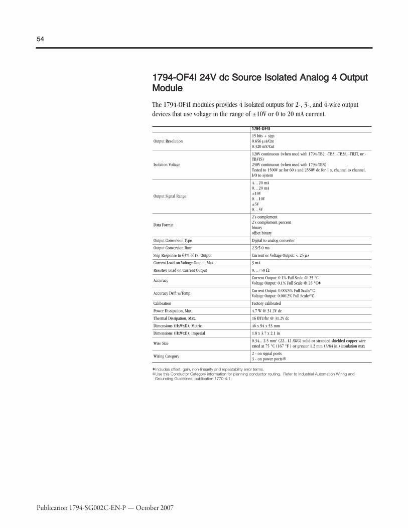
54
Publication 1794-SG002C-EN-P — October 2007
11779944--OOFF44II 2244VV ddcc SSoouurrccee IIssoollaatteedd AAnnaalloogg 44 OOuuttppuuttMMoodduullee
The 1794-OF4I modules provides 4 isolated outputs for 2-, 3-, and 4-wire outputdevices that use voltage in the range of ±10V or 0 to 20 mA current.
1794-OF4I
Output Resolution15 bits + sign0.656 μA/Cnt0.320 mV/Cnt
Isolation Voltage
120V continuous (when used with 1794-TB2, -TB3, -TB3S, -TB3T, or -TB3TS)250V continuous (when used with 1794-TBN)Tested to 1500V ac for 60 s and 2550V dc for 1 s, channel to channel,I/O to system
Output Signal Range
4…20 mA0…20 mA±10V0…10V±5V0…5V
Data Format
2’s complement2’s complement percentbinaryoffset binary
Output Conversion Type Digital to analog converter
Output Conversion Rate 2.5/5.0 ms
Step Response to 63% of FS, Output Current or Voltage Output: < 25 μs
Current Load on Voltage Output, Max. 3 mA
Resistive Load on Current Output 0…750 Ω
AccuracyCurrent Output: 0.1% Full Scale @ 25 °CVoltage Output: 0.1% Full Scale @ 25 °C✶
Accuracy Drift w/Temp.Current Output: 0.0025% Full Scale/°CVoltage Output: 0.0012% Full Scale/°C
Calibration Factory calibrated
Power Dissipation, Max. 4.7 W @ 31.2V dc
Thermal Dissipation, Max. 16 BTU/hr @ 31.2V dc
Dimensions (HxWxD), Metric 46 x 94 x 53 mm
Dimensions (HxWxD), Imperial 1.8 x 3.7 x 2.1 in
Wire Size0.34... 2.5 mm2 (22...12 AWG) solid or stranded shielded copper wirerated at 75 °C (167 °F ) or greater 1.2 mm (3/64 in.) insulation max
Wiring Category2 - on signal ports3 - on power ports�
✶Includes offset, gain, non-linearity and repeatability error terms.�Use this Conductor Category information for planning conductor routing. Refer to Industrial Automation Wiring and
Grounding Guidelines, publication 1770-4.1.

55
Publication 1794-SG002C-EN-P — October 2007
11779944--OOEE88HH HHAARRTT EEnnaabblleedd AAnnaalloogg 88 OOuuppuutt MMoodduullee
The 1794-OE8H is a HART enabled analog output module that works with HARTenabled field devices that use current in the 0 to 20 mA range. Use with 2 or 3 wiredevices. This module provides wire-off detection on a per-channel basis. This modulecan only be used on ControlNet or EtherNet/IP networks. One HART field device perchannel.
1794-OE8HOutput Resolution 13 bits
Isolation Voltage50V (continuous), Basic Insulation TypeRoutine tested at 850V dc for 1 s, between field side and systemNo isolation between individual channels
Output Signal Range4…20 mA (user configurable)0…20 mA (user configurable)
Data Format Configurable
Output Conversion Type —
Output Conversion Rate 10 ms for all channels
Step Response to 63% of FS, Output 13 ms to 99% of FS / 115 ms during HART comms
Current Load on Voltage Output, Max. 0…22 mA @ > 15V
Resistive Load on Current Output 0…680 Ω @ 22 mA, 0…770 Ω @ 20 mA
Accuracy 0.1% Full Scale @ 20 °C (68 °F)
Accuracy Drift w/Temp. 0.010% per °C of output signal range
Calibration —
Power Dissipation, Max. 6.1 W
Thermal Dissipation, Max. 20.8 BTU/hr
Dimensions (HxWxD), Metric 46 x 94 x 75 mm
Dimensions (HxWxD), Imperial 1.8 x 3.7 x 2.95 in
Wire Size0.34... 2.5 mm2 (22...12 AWG) solid or stranded shielded copper wirerated at 75 °C (167 °F ) or greater 1.2 mm (3/64 in.) insulation max
Wiring Category2 - on signal ports2 - on power ports✶
✶Use this Conductor Category information for planning conductor routing. Refer to Industrial Automation Wiring andGrounding Guidelines, publication 1770-4.1.

56
Publication 1794-SG002C-EN-P — October 2007
11779944--OOEE1122 2244VV ddcc SSeelleeccttaabbllee AAnnaalloogg 1122 OOuuttppuuttMMoodduullee
1794-OE12 module is a High Density analog output module, capable of providingcurrent in the range of 0 to 20mA or voltage in the range of +/-10V, depending on theuser configuration. Out of Range status bit exists for each channel.
1794-OE12Output Resolution stbUCString::convert: Character with charcode: "913" met
Isolation Voltage50V (continuous), Basic Insulation TypeType tested at 850V dc for 60 s, between field side and systemNo isolation between individual channels
Output Signal Range0 mA output until module is configured4…20 mA (user configurable)0…20 mA (user configurable)
Data Format Configurable
Output Conversion Type Digital-to-Analog Converter
Output Conversion Rate —
Step Response to 63% of FS, Output ~70% 1st convert; 96% 2nd convert; 100% 3rd convert
Current Load on Voltage Output, Max. 3 mA max
Resistive Load on Current Output 0…750 Ω over full power supply range
AccuracyCurrent Output: 0.1% Full Scale @ 25 °CVoltage Output: 0.1% Full Scale @ 25 °C
Accuracy Drift w/Temp.Current Output: 0.004% Full Scale/°CVoltage Output: 0.004% Full Scale/°C
Calibration None required
Power Dissipation, Max. 4.0 W @ 31.2V dc; 4.3 W @ 24V dc; 4.0 W @ 10.0V dc
Thermal Dissipation, Max. —
Dimensions (HxWxD), Metric 94.0 x 94.0 x 53.3 mm (with module installed in base)
Dimensions (HxWxD), Imperial 3.7 x 3.7 x 2.1 in (with module installed in base)
Wire Size0.34... 2.5 mm2 (22...12 AWG) solid or stranded shielded copper wirerated at 75 °C (167 °F ) or greater 1.2 mm (3/64 in.) insulation max
Wiring Category2 - on signal ports2 - on power ports✶
✶Use this Conductor Category information for planning conductor routing. Refer to Industrial Automation Wiring andGrounding Guidelines, publication 1770-4.1.
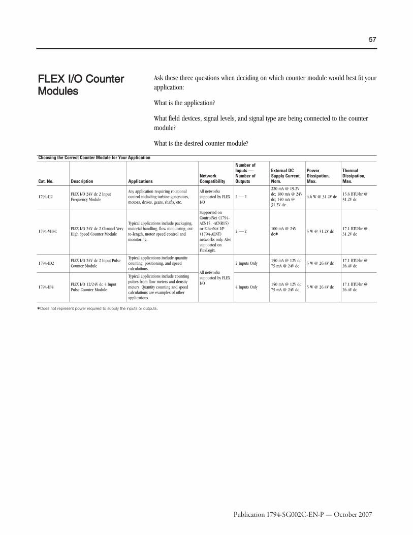
57
Publication 1794-SG002C-EN-P — October 2007
FFLLEEXX II//OO CCoouunntteerrMMoodduulleess
Ask these three questions when deciding on which counter module would best fit yourapplication:
What is the application?
What field devices, signal levels, and signal type are being connected to the countermodule?
What is the desired counter module?
Choosing the Correct Counter Module for Your Application
Cat. No. Description ApplicationsNetworkCompatibility
Number ofInputs ⎯⎯Number ofOutputs
External DCSupply Current,Nom.
PowerDissipation,Max.
ThermalDissipation,Max.
1794-IJ2FLEX I/O 24V dc 2 InputFrequency Module
Any application requiring rotationalcontrol including turbine generators,motors, drives, gears, shafts, etc.
All networkssupported by FLEXI/O
2 ⎯ 2
220 mA @ 19.2Vdc; 180 mA @ 24Vdc; 140 mA @31.2V dc
4.6 W @ 31.2V dc15.6 BTU/hr @31.2V dc
1794-VHSCFLEX I/O 24V dc 2 Channel VeryHigh Speed Counter Module
Typical applications include packaging,material handling, flow monitoring, cut-to-length, motor speed control andmonitoring.
Supported onControlNet (1794-ACN15, -ACNR15)or EtherNet I/P(1794-AENT)networks only. Alsosupported onFlexLogix.
2 ⎯ 2100 mA @ 24Vdc✶
5 W @ 31.2V dc17.1 BTU/hr @31.2V dc
1794-ID2FLEX I/O 24V dc 2 Input PulseCounter Module
Typical applications include quantitycounting, positioning, and speedcalculations.
All networkssupported by FLEXI/O
2 Inputs Only150 mA @ 12V dc75 mA @ 24V dc
5 W @ 26.4V dc17.1 BTU/hr @26.4V dc
1794-IP4FLEX I/O 12/24V dc 4 InputPulse Counter Module
Typical applications include countingpulses from flow meters and densitymeters. Quantity counting and speedcalculations are examples of otherapplications.
4 Inputs Only150 mA @ 12V dc75 mA @ 24V dc
5 W @ 26.4V dc17.1 BTU/hr @26.4V dc
✶Does not represent power required to supply the inputs or outputs.

58
Publication 1794-SG002C-EN-P — October 2007
Conformal Coated Description
1794-IJ2KANSI / ISA-S71.04-1985, Class G1, G2, and G3 environmentsCEI IEC 6065A-4 Class 1 and 2 environmentsUL 746E
11779944--IIJJ22 2244VV ddcc 22 IInnppuutt FFrreeqquueennccyy MMoodduullee
The 1794-IJ2 is essentially a tachometer with the capability of reporting frequency,acceleration, and direction. Outputs are activated by alarms. Input devices range frommagnetic pickup to flowmeters, to incremental encoders to proximity detectors.This intelligent I/O module is designed to perform high-speed frequency algorithms.The module provides 2 frequency inputs, 2 gate inputs, and 2 outputs. The frequencyinputs are capable of accepting frequencies up to 32KHz. The module accepts andreturns binary data.The 1794-IJ2 measures frequency over a user-specified time interval. A frequencycalculation can start before the time interval has elapsed, if a user-specified numberof frequency input pulses have occurred.The module's primary target is high-speed, accurate frequency measurement. As such,a high-speed internal clock is synchronized with the frequency input to count over auser-selected sampling time or a user-defined number of frequency input pulses.Power to the module is supplied from the external power supply. All power for inputdevices (24V dc) is supplied by the I/O module. Outputs are used to set alarmsdepending on the input conditions.
The 1794-IJ2 module accepts the following frequency inputs:
� 24V dc IEC1+ proximity switch as defined by standard IEC 1131-2
� 24V dc contact switch with wire off capability
� 500 mV ac magnetic pickup
� 50 mV ac magnetic pickup
� 6V ac vortex� 3V ac vortex
The 1794-IJ2 module accepts the following gate inputs:
� 24V dc IEC1+ proximity switch as defined by standard IEC 1131-2
� 24V dc contact switch
� 500 mV ac magnetic pickup
� 50 mV ac magnetic pickup
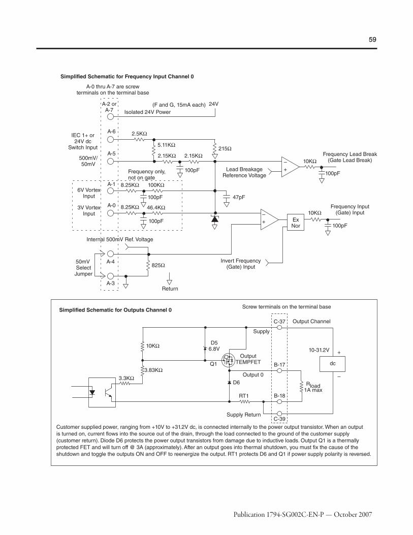
59
Publication 1794-SG002C-EN-P — October 2007

60
Publication 1794-SG002C-EN-P — October 2007

61
Publication 1794-SG002C-EN-P — October 2007
1794-IJ2
Processing Time ≤4 ms
Input Frequency, Max. 1…32 kHz w/sine wave; 1…32 kHz w/square wave input
Frequency Value, Max. 32,767 or 3,276.7 (dependent on range)
Input Pulse Width 20 μs min
Voltage, On-State Input, Min. 10V (24V IEC+1 proximity, encoder input or switch inputs)
Voltage, On-State Input, Nom. 24V dc
Voltage, On-State Input, Max. Limited to isolated 24V dc power supply
Current, On-State Input, Min. 2.0 mA
Current, On-State Input, Nom. 9.0 mA
Current, On-State Input, Max. 10.0 mA
Voltage, Off-State Input, Max. 5.0V dc on 24V dc IEC1+ Terminal
Current, Off-State Input, Max. 1.5 mA into 24V dc IEC1+ Terminal
Wire-Off Detection 0.4 mA for proximity, encoder, or contact switch with 50 kW shunt resistor
Impedance, Frequency Input
>5 kΩ for 50 mV extended magnetic pickup>5 kΩ for 500 mV magnetic pickup>10 kΩ for 3V vortex flowmeter>10 kΩ for 6V vortex flowmeter>2.5 kΩ for 24V dc IEC1+ proximity or encoder input>2.5 kΩ for 24V dc contact switch input
Impedance, Gate Input
>5 kΩ for 50 mV extended magnetic pickup>5 kΩ for 500 mV magnetic pickup>2.5 kΩ for 24V dc IEC1+ proximity or encoder input>2.5 kΩ for 24V dc contact switch input
Output Voltage Source Customer supplied
Voltage, On-State Output, Min. 10V dc
Voltage, On-State Output, Nom. 24V dc
Voltage, On-State Output, Max. 31.2V dc
Current, On-State Output, Min. 1.0 mA per output
Current, On-State Output, Max. 1.0 A per channel sourced out of module✶
Output Surge Current, Max. 2 A for 50 ms, repeatable every 2 s
Voltage Drop, On-State Output, Max. 0.9V dc @ 1 A
Dimensions (HxWxD), Metric 46 x 94 x 53 mm
Dimensions (HxWxD), Imperial 1.8 x 3.7 x 2.1 in
Output ControlOutputs individually assignable to:Frequency,% full scale, or acceleration alarm
Output Switching TimeTriggered by frequency alarm or acceleration alarmTurn On: < 0.5 msTurn Off: < 1 ms
✶Current Limited: All outputs can be on simultaneously without derating.

62
Publication 1794-SG002C-EN-P — October 2007
11779944--VVHHSSCC 2244VV ddcc 22 CChhaannnneell VVeerryy HHiigghh SSppeeeeddCCoouunntteerr MMoodduullee
A counter module has two incremental quadrature encoder interfaces each with threeinputs (A, B, and Z). Each input module has ± inputs for connection to pulsetransmitters with complementary or non-complementary signals.The counter can count pulses of one or two pulse trains for up/down counting anddetection of a selectable number of edges (X1, X2, X4). Each of the two counters hasan upper limit of 1MHz, a 24-bit counter register, a preset register, and a latchregister.Power to the module is supplied from an external 24V power supply. The 1794-VHSChas two outputs that can be configured for overlapping, multiple windows, and/orpulse width modulation.
When using ControlNet systems, this module must be used with 1794-ACN15 or -ACNR15 Series B or later ControlNet adapters. When using EtherNet/IP systems, thismodule must be used with a 1794-AENT/A module with firmware at revision 2.xx orlater, along with a FlexLogix local controller.
1794-VHSCInput Groups 2 groups of A/A, B/B, and Z/Z pairs with 5V dc or 15…24V dc terminations
Input Frequency, Max.1.0 MHz counter and encoder X1 (no filters)500 kHz encoder X2 (no filters)250 kHz encoder X4 (no filters)
Voltage, On-State Input, Min.5V dc terminations: >2.6V dc15…24V dc terminations: >12.5V dc
Voltage, On-State Input, Max.5V dc terminations: ±6V15…24V dc terminations: Refer to derating curve
Voltage, Off-State Input, Min.5V dc terminations: ≤1.25V dc15…24V dc terminations: ≤1.8V dc
Current, On-State Input, Min. >5 mA
Current, Off-State Input, Max. ≤0.250 mA
Input Filter Selections 5: Off, 10 μs, 100 μs, 1.0 ms, 10.0 ms per A/B/Z group
Output Control Outputs can be tied to 8 compare windows
Output Supply Voltage Range 5…7V dc or 10…31V dc
Leakage Current, Off-State Output, Max ≤0.3 mA
Voltage Drop, On-State Output, Max.5V operation - 0.5 A12…24V operation - 1.0 A
Current, On-State Output, Max.5V operation - 0.5 A12…24V operation - 1.0 A
Current per Output Pair, Max.5V operation - 0.9 A12…24V operation - 4.0 A
Short Circuit Current5V operation - 0.9V dc @ 0.5 A✶12…24V operation - 0.9V dc @ 1.0 A
Dimensions (HxWxD), Metric 45.7 x 94.0 x 53.3 mm
Dimensions (HxWxD), Imperial 1.8 x 3.7 x 2.1 in
Output Delay Time, OFF to ON 25 μs (load dependent)
Output Delay Time, ON to OFF 150 μs (load dependent)
✶Outputs are short circuit protected and turned off until power is cycled.
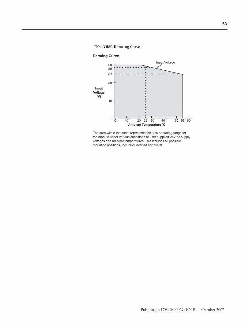
63
Publication 1794-SG002C-EN-P — October 2007
1794-VHSC Derating Curve

64
Publication 1794-SG002C-EN-P — October 2007
11779944--IIDD22 2244VV ddcc 22 IInnppuutt PPuullssee CCoouunntteerr MMoodduullee
The 1794-ID2 module is a 2-channel counter used in applications where pulsecounting is required. Typical input devices include quadrature incremental encoderswith or without reference and/or gate function and pulse transmitters. You can useone or two pulse trains.
1794-ID2Input Pulse Width Each signal condition must be stable for at least 2 ms to be recognized
Input Groups 2 groups of A, B, Z, G inputs
Counting Frequency (kHz), Max. 100
Cable Type Input: Belden 8761
Wiring Category 2✶
Conductor Length, Max 1000 ft (304.8 m)
Dimensions (HxWxD), Metric 46 x 94 x 53 mm
Dimensions (HxWxD), Imperial 1.8 x 3.7 x 2.1 in
Input Signal Range3 mA @ 6V dc9 mA @ 12V dc15 mA @ 24V dc
✶Use this conductor category information for planning conductor routing. Refer to publication 1770-4.1, Industrial AutomationWiring and Grounding Guidelines.
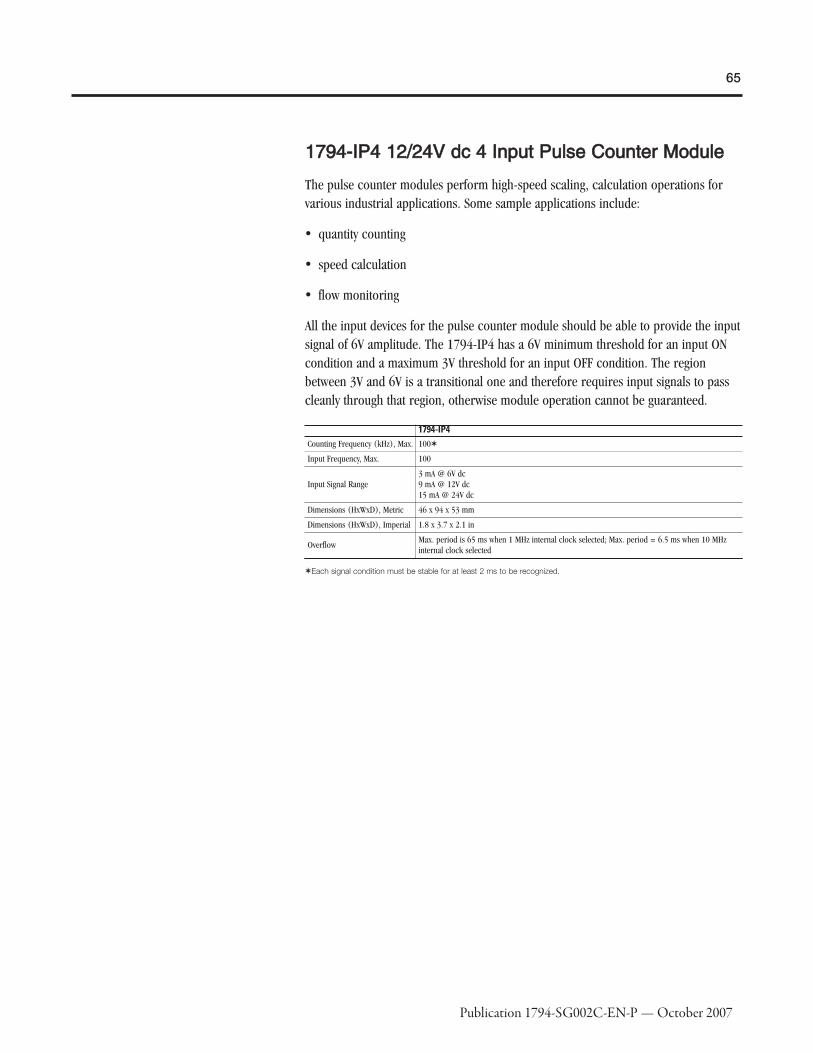
65
Publication 1794-SG002C-EN-P — October 2007
11779944--IIPP44 1122//2244VV ddcc 44 IInnppuutt PPuullssee CCoouunntteerr MMoodduullee
The pulse counter modules perform high-speed scaling, calculation operations forvarious industrial applications. Some sample applications include:
� quantity counting
� speed calculation
� flow monitoring
All the input devices for the pulse counter module should be able to provide the inputsignal of 6V amplitude. The 1794-IP4 has a 6V minimum threshold for an input ONcondition and a maximum 3V threshold for an input OFF condition. The regionbetween 3V and 6V is a transitional one and therefore requires input signals to passcleanly through that region, otherwise module operation cannot be guaranteed.
1794-IP4Counting Frequency (kHz), Max. 100✶
Input Frequency, Max. 100
Input Signal Range3 mA @ 6V dc9 mA @ 12V dc15 mA @ 24V dc
Dimensions (HxWxD), Metric 46 x 94 x 53 mm
Dimensions (HxWxD), Imperial 1.8 x 3.7 x 2.1 in
OverflowMax. period is 65 ms when 1 MHz internal clock selected; Max. period = 6.5 ms when 10 MHzinternal clock selected
✶Each signal condition must be stable for at least 2 ms to be recognized.
66
Publication 1794-SG002C-EN-P — October 2007
Step 3 - Select:
� the appropriate terminal base unitfor your module and system
Selecting a Terminal BaseUnitEach FLEX I/O module requires a terminal base unit that snaps onto the DIN Rail tothe right of the I/O adapter. The terminal bases provide terminal connection pointsfor I/O wiring and plug together to form the backplane. They are available with screwor spring terminations.
General Specifications
Cat. No.�� Description Purpose
1794-TB2FLEX I/O 2-WireCage-Clamp TerminalBase Unit
A generic version of the 1794-TB3 below
1794-TB3FLEX I/O 3-WireCage-Clamp TerminalBase Unit
Primarily intended for use with input modules when using 3-wire input proximity switches⎯ can also be used with output modules
1794-TB3SFLEX I/O 3-WireSpring-ClampTerminal Base Unit
A spring clamp version of the cage clamp 1794-TB3 above ⎯ provides faster, simpler wireinstallation
1794-TB32FLEX I/O 32-PointCage-Clamp TerminalBase Unit
A 32-point version of the 1794-TB3 to be used with 32-point digital modules and 1794-IB16D
1794-TB32SFLEX I/O 32-PointSpring-ClampTerminal Base Unit
A spring clamp version of the 1794-TB32
1794-TB3G
FLEX I/O 3-WireGrounded Cage-Clamp Terminal BaseUnit
A screw clamp terminal base unit with individual grounding used with certain analogmodules
1794-TB3GS
FLEX I/O 3-WireGrounded Spring-Clamp Terminal BaseUnit
A spring clamp version of the 1794-TB3G
1794-TB3TFLEX I/O Cage-ClampTemperatureTerminal Base Unit
Required with the 1794-IT8 module (when used in thermocouple mode) ⎯ also provideschassis ground connections for the 1794-IR8 and analog modules
1794-TB3TSFLEX I/O Spring-Clamp TemperatureTerminal Base Unit
A spring clamp version of the 1794-TB3T
1794-TBKDProposed Product:FLEX I/O Cage-ClampTerminal Base Unit
A spring clamp version of the 1794-TB3T
1794-TBNFLEX I/O Screw-Clamp Terminal BaseUnit
Provides screw terminals to accept larger gauge wires plus cover for I/O wiring
1794-TBNF✶FLEX I/O Screw-Clamp FusedTerminal Base Unit
Provides eight 5 x 20 mm fuses, screw terminals, plus a cover for I/O wiring ⎯ shippedwith fuses for the 1794-OA8 module; can be used to fuse the 1794-OM8 and -OW8modules with a replacement fuse (see the installation instructions)
✶Contains eight 5x20 mm fuses (one for each even-numbered terminal - 0 through 14 on row B). Shipped with 1.6 A, 250Vac Slow Blow fuses suitable for 1794-OA8 ac output module. Refer to individual installation instructions for fusingrecommendations for other modules. Littelfuse PN23901.6, A-B PN94171304, SAN-O PNSD6-1.6A.�Isolation Voltage, Channel to Channel is determined by the inserted module.

67
Publication 1794-SG002C-EN-P — October 2007
Conformal coated versions of standard modules have the letter K in the last position ofthe catalog number, before the series designation.
Conformal Coated Description
1794-TB3KANSI / ISA-S71.04-1985, Class G1, G2, and G3 environmentsCEI IEC 6065A-4 Class 1 and 2 environmentsUL 746E
1794-TB3GK
1794-TBNK
The following table illustrates the recommended FLEX I/O terminal base unit(s) foreach module. Many terminal base units can be used with most modules, but auxiliaryterminal strips may be required.

68
Publication 1794-SG002C-EN-P — October 2007
FLEX I/O Product Cat. No. Terminal Base Unit
120V ac Input Modules
1794-IA8 1794-TBN, 1794-TB2, 1794-TB3, 1794-TB3S, 1794-TBKD✶.
1794-IA8I 1794-TBN, 1794-TB2, 1794-TB3, 1794-TB3S, 1794-TBKD�
1794-IA16 1794-TB3, 1794-TB3S, 1794-TBN�‡
220V ac Input Module 1794-IM8 1794-TBN�
120V ac Output Modules
1794-OA8 1794-TBNF, 1794-TB2, 1794-TB3, 1794-TB3S, 1794-TBN, 1794-TBKD�
1794-OA8I 1794-TBNF, 1794-TB2, 1794-TB3, 1794-TB3S, 1794-TBN, 1794-TBKD�
1794-OA16 1794-TB3, 1794-TB2, 1794-TB3S, 1794-TBN, 1794-TBKD�§
220V ac Output Module 1794-OM8 1794-TBNF, 1794-TBN�
24V dc Input Modules
1794-IB8 1794-TB3, 1794-TB3S�
1794-IB16 1794-TB3, 1794-TB3S�
1794-IB16D 1794-TB32, 1794-TB32S�
1794-IB32 1794-TB32, 1794-TB32S�
1794-IV16 1794-TB2, 1794-TB3, 1794-TB3S, 1794-TBKD�
24V dc Input/Output Modules1794-IB10XOB6 1794-TB3, 1794-TB3S�
1794-IB16XOB16P 1794-TB32, TB32S�
48V dc Input Module 1794-IC16 1794-TB3, 1794-TB3S�
24V dc Output Modules
1794-OB8 1794-TB2, 1794-TB3, 1794-TB3S, 1794-TBKD�
1794-OB8EP 1794-TB3, 1794-TB2, 1794-TB3S, 1794-TBN, 1794-TBKD�
1794-OB16 1794-TB2, 1794-TB3, 1794-TB3S, 1794-TBKD�
1794-OB16D 1794-TB3, 1794-TB3S, 1794-TBKD�
1794-OB16P 1794-TB2, 1794-TB3, 1794-TB3S, 1794-TBKD�
1794-OB32P 1794-TB32, 1794-TB32S�
1794-OV16 1794-TB3, 1794-TB3S�
1794-OV16P 1794-TB3, 1794-TB3S�
48V dc Output Module 1794-OC16 1794-TB3, 1794-TB2, 1794-TB3S, 1794-TBKD�
Relay Module 1794-OW8 1794-TBNF, 1794-TBN, 1794-TB2, 1794-TB3, 1794-TB3S, 1794-TBKD�
24V dc Analog Input Modules
1794-IE8 1794-TB3, 1794-TB2, 1794-TB3S, 1794-TB3T, 1794-TB3TS�
1794-IF4I 1794-TB3, 1794-TB2, 1794-TB3S, 1794-TB3T, 1794-TB3TS, 1794-TBN�
1794-IR8 1794-TB3, 1794-TB2, 1794-TB3S, 1794-TB3T, 1794-TB3TS�
1794-IRT8 1794-TB3G, 1794-TB3GS�
1794-IT8 1794-TB3T, 1794-TB2, 1794-TB3, 1794-TB3S, 1794-TB3TS�♣
24V dc Analog Input/Output Modules
1794-IE4XOE2 1794-TB3, 1794-TB2, 1794-TB3S, 1794-TB3T, 1794-TB3TS�
1794-IF2XOF2I 1794-TB3, 1794-TB2, 1794-TB3S, 1794-TB3T, 1794-TB3TS, 1794-TBN�
24V dc Analog Output Modules
1794-OE4 1794-TB3, 1794-TB2, 1794-TB3S, 1794-TB3T, 1794-TB3TS, 1794-TBN�
1794-OF4I 1794-TB3, 1794-TB2, 1794-TB3S, 1794-TB3T, 1794-TB3TS, 1794-TBN�
Counter Modules
1794-IJ2 1794-TB3G, 1794-TB3GS�
1794-VHSC 1794-TB3G, 1794-TB3GS�➤�
1794-ID2 1794-TB3, 1794-TB3S, 1794-TBN, 1794-TBNF��
1794-IP4 1794-TB3, 1794-TB3S, 1794-TBN, 1794-TBNF��
SCANport Module 1203-FB1 1203-FB1
✶Recommended terminal base is in bold text�Recommended terminal base is in bold text.‡Auxiliary terminal strips are required when using the 1794-TBN for the 1794-IA16 and 1794-IA16.§Auxiliary terminal strips are required when using the 1794-TBN for the 1794-OA16 and 1794-IA16.♣You can use a 1794-TB2, 1794-TB3, or 1794-TB3S for mV inputs only.➤For use with 1794-ACN15, 1794-ANCR15, and 1794-AENT only.�Auxiliary terminal strips are required when using the 1794-TBN or 1794-TBNF for this catalog number.

69
Publication 1794-SG002C-EN-P — October 2007
General Specifications
Cat. No.�� Connections Ternination TypeUsed inApplications
CurrentCapacity, Max.
Dimensions(HxWxD), MetricDimensions(HxWxD), Imperial Wire Size Wiring Category Certifications
1794-TB2 16 I/O; 18 common; 2 +V
Up to 132V ac/156V dc
1094 x 94 x 69 mm3.7 x 3.7 x 2.7 in
22…12 AWG(0.34 mm2…2.5mm2) strandedcopper wire ratedat 75 °C or higher3/64 in (1.2 mm)insulation max.
2‡
UL, CSA, CE:Class I Division2 certifiedGroups A, B, C,D certifiedClass I Zone 2Group IICcertified
1794-TB316 I/O; 18 common; 18 +V
1794-TB3S
Moduledependent‡
1794-TB3232 I/O; 8 common; 8 +V
Up to 31.2V dc1794-TB32S
1794-TB3G 36 I/O; 2 common; 2 +V; 10chassis ground1794-TB3GS 2‡
1794-TB3T16 I/O; 10 common; 4 +V; 8chassis ground; 2 sets of CJCto be used with temperaturemodules
Up to 132V ac/156V dc
Moduledependent‡
1794-TB3TS 2‡
1794-TBN16 I/O; 2 common; 2 +V� 264V ac/dc
Moduledependent‡1794-TBNF✶
✶Contains eight 5x20 mm fuses (one for each even-numbered terminal - 0 through 14 on row B). Shipped with 1.6 A, 250V ac Slow Blow fuses suitable for 1794-OA8 ac output module. Referto individual installation instructions for fusing recommendations for other modules. Littelfuse PN23901.6, A-B PN94171304, SAN-O PNSD6-1.6A.�Isolation Voltage, Channel to Channel is determined by the inserted module.‡Use this conductor category information for planning conductor routing. Refer to publication 1770-4.1, "Industrial
Automation Wiring and Grounding Guidelines."

70
Publication 1794-SG002C-EN-P — October 2007
WWiirriinngg DDiiaaggrraammss 11779944--TTBB22,, --TTBB33,, aanndd --TTBB33SS

71
Publication 1794-SG002C-EN-P — October 2007
11779944--TTBB33TT aanndd --TTBB33TTSS

72
Publication 1794-SG002C-EN-P — October 2007
11779944--TTBB33GG aanndd --TTBB33GGSS

73
Publication 1794-SG002C-EN-P — October 2007

74
Publication 1794-SG002C-EN-P — October 2007
11773344--TTBB3322 aanndd --TTBB3322SS

75
Publication 1794-SG002C-EN-P — October 2007

76
Publication 1794-SG002C-EN-P — October 2007
11779944--TTBBNN aanndd --TTBBNNFF

77
Publication 1794-SG002C-EN-P — October 2007
11779944--TTBBNN aanndd --TTBBNNFF AAlltteerrnnaattee WWiirriinngg
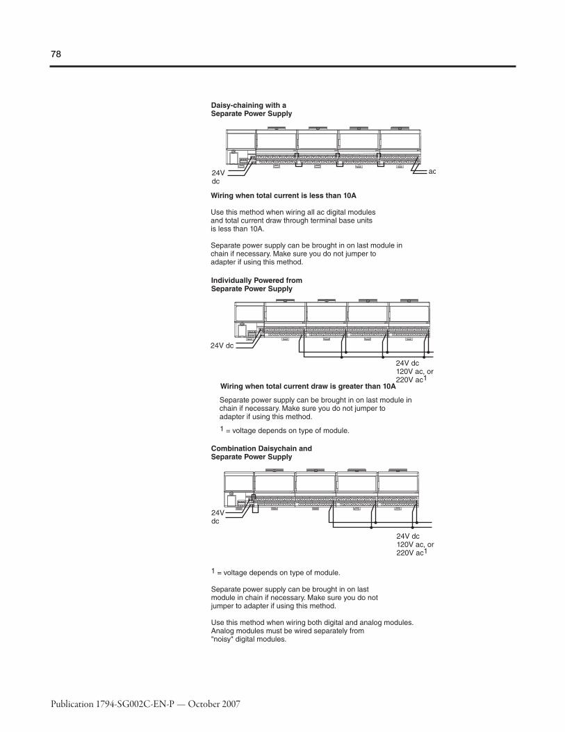
78
Publication 1794-SG002C-EN-P — October 2007

79
Publication 1794-SG002C-EN-P — October 2007
Step 4 - Select:
� if power consumption exceeds themaximum for a single power supply,install additional power supplies
Selecting a Power SupplyThe I/O modules are interfaced to the I/O link through an I/O adapter module with abuilt-in 24V dc input power supply. The I/O modules receive power from theadapter/power supply through the backplane. The 120V ac to 24V dc power supply(1794-PS13 or -PS3) is also available for powering the adapter/power supply. (Whenproviding power for the 1794-FLA extended-local I/O FlexLogix adapter, treat theadapter as a communication adapter, not as an I/O module.)
Cat. No.
Power SupplyInput Voltage,Nom.
Power SupplyInput Power
Apparent InputPower, Max.
Transformer Load,Max.
Output Current,Max.
Dimensions(HxWxD), Metric
Dimensions(HxWxD), Imperial
Output Voltage,Nom.
1794-PS3 120V/220V ac 86 W 205 VA 250 VA 3.0 A✶ 87 x 94 x 69 mm 3.4 x 3.7 x 2.7 in +24V dc
1794-PS13 120V/220V ac 36 W 53 VA 90 VA 1.3 A 87 x 68 x 69 mm 3.4 x 2.7 x 2.7 in +24V dc
✶Horizontal mount; 2.8 A all other mounting.
PPoowweerr SSuuppppllyy DDeeffiinniittiioonnssModule Supply Voltage ⎯ This is typically either 120V ac or 24V dc nominalvoltage that is supplied from an external power source wired to the module terminalbase.
FLEXBus Current ⎯ This is the logic current consumed by the module. The FLEXadapter provides a 5V dc supply via it's internal connector through the successivemodule terminal base connectors to which it is attached. FLEXBus current consumedby a module has NO affect on the sizing of the FLEX I/O power supply.
FLEX I/O chassis FLEXBus current is limited by what current the adapter 5V dc cansupport across the terminal base internal FLEXBus connectors. FLEX I/O 1794-ASB, -ACN15, and -ACNR15 adapters can supply a maximum of 640 mA at 5V dc. Since nomore than eight FLEX I/O modules can be connected to an adapter, no combination ofeight FLEX I/O modules will ever draw more than the adapter can supply.
The 1794-PS13 power supply is capable of supplying a maximum of 1.3 A at 24V dc.The output surge current is sufficient to drive four adapters with a surge of 23 A for 2ms each operating at 24V dc.
The 1794-PS3 power supply is capable of supplying a maximum of 3 A✶ at 24V dc.The output surge current is sufficient to drive six adapters with a surge of 23 A for 2ms each operating at 24V dc.
Non-Allen-Bradley dc power supplies can also be used, but should operate within thespecifications for the devices they are powering. Size the power supply by calculatingthe total current consumed by summing the currents for each of the modules used forthe power supply operating voltage applied.

80
Publication 1794-SG002C-EN-P — October 2007
Digital Input Modules require supplied 24V dc (19.2…3.12V dc) and consumethe currents listed in the module specifications.
Digital Output Module require supplied 24V dc (19.2…3.12V dc) and consumethe currents listed in the module specifications plus the total current consumed bytheir loads. The load current is limited by the maximum load current and surgelisted.
Combination Digital Modules have a combination of inputs and outputs. Thecurrent load should be determined as described for the combined input and outputspecifications listed.
Analog Input Modules require supplied 24V dc (19.2…3.12V dc) and consumethe currents listed in the module specifications. In addition, adequate power must besupplied to the 1794-IE8 and -IF4I transmitters to deliver input terminal voltage ordrive 20 mA into the input impedance listed. This power source may be the same asthe module power and can be included in the power supply calculation.
Analog Output Modules require supplied 24V dc (19.2…3.12V dc) and consumethe currents listed plus the total current consumed by their loads. The load current islimited by maximum current or resistive load permitted per channel.
Combination Analog Modules have a combination of analog inputs and outputs.The current load should be determined as described previously for the combinedmodule and output specifications listed. The output load current is limited by themaximum current or resistive load permitted per channel. In addition, adequatepower must be supplied to the 1794-IE8 and -IF4I transmitters to deliver inputterminal voltage or drive 20 mA into the input impedance listed. This power sourcemay be the same as the module power and can be included in the power supplycalculation.
Counter Modules require module power, transmitter input power, and in somecases output load power. If output load power is required, use a separate powersupply for output load power for noise immunity.
✶This refers to horizontal mounting: 2.8 A maximum for all other mountings. Refer tothe derating current in the installation instructions for that module.

81
Publication 1794-SG002C-EN-P — October 2007
PPoowweerr RReeqquuiirreemmeennttss aanndd TTrraannssffoorrmmeerr SSiizziinngg
� Use the real power value in watts for determining the amount of heat dissipation youwill have inside the enclosure.
� Use the apparent power value in VA for estimating power distribution sizing.
� Use the transformer load value in VA of each power supply plus all other loads on atransformer to determine the required transformer size.

82
Publication 1794-SG002C-EN-P — October 2007
Step 5 - Select:
� panel mount or DIN Rail mount
� appropriate number of panels orDIN Rails based on the number ofmodules and the physicalrequirements
� one end cap per controller system
Mounting the FLEX I/OSystemYou can horizontally or vertically mount the FLEX I/O or FLEX Ex system on a standard35 mm DIN Rail. The adapter and terminal base easily snap on the DIN Rail by hand.Use a flat-blade screwdriver to remove components from the DIN Rail.
Screw holes allow you to horizontally or vertically panel-mount your system in anenclosure. Maintain at least 25mm (1 inch) of air space around you Flex I/O system.Maintain at least 25 mm (1 inch) air space around your FLEX I/O system installation.

83
Publication 1794-SG002C-EN-P — October 2007
When properly installed, FLEX I/O and FLEX Ex are grounded through the DIN Rail tochassis ground. Use zinc-plated, yellow-chromated steel DIN Rail to assure propergrounding. Using other DIN Rail materials (e.g. aluminum, plastic, etc.) which cancorrode, oxidize, or are poor conductors can result in improper or intermittentplatform grounding.
If installing FLEX I/O or FLEX Ex on non-recommended DIN Rail materials, use themounting holes provided in each terminal base or a 1794-NM1 mounting kit withapproved mounting bracket. Use mounting screws with star washers to provide theFLEX I/O or FLEX Ex platform with a chassis ground connection that is not likely to beaffected by shock, vibration, or oxidation over time.
The hook (on the terminal base) and adjacent connection point (on thecommunication adapter) keep the terminal bases tight together. These componentsare capable of maintaining a reliable connection in case of shock and/or vibration.Refer to the environmental conditions informations in each module's specifications.
11779944--CCEE11 aanndd --CCEE33 EExxtteennddeerr CCaabblleess
Use the optional 1794-CE1 (0.3m, 1ft) or 1794-CE3 (0.9m, 3ft) extender cable (oneper system) to arrange your system in two rows or split your system into horizontaland vertical orientation. The cable can be used between any module or betweenadapters and modules.
These cables are also used to connect the 1794-FLA to a FlexLogix controller for anextended loacl FLEX rail.
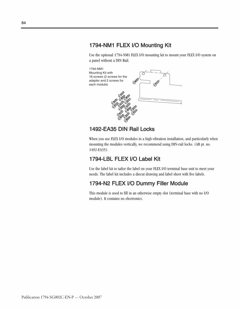
84
Publication 1794-SG002C-EN-P — October 2007
11779944--NNMM11 FFLLEEXX II//OO MMoouunnttiinngg KKiitt
Use the optional 1794-NM1 FLEX I/O mounting kit to mount your FLEX I/O system ona panel without a DIN Rail.
11449922--EEAA3355 DDIINN RRaaiill LLoocckkss
When you use FLEX I/O modules in a high-vibration installation, and particularly whenmounting the modules vertically, we recommend using DIN-rail locks. (AB pt. no.1492-EA35).
11779944--LLBBLL FFLLEEXX II//OO LLaabbeell KKiitt
Use the label kit to tailor the label on your FLEX I/O terminal base unit to meet yourneeds. The label kit includes a diecut drawing and label sheet with five labels.
11779944--NN22 FFLLEEXX II//OO DDuummmmyy FFiilllleerr MMoodduullee
This module is used to fill in an otherwise empty slot (terminal base with no I/Omodule). It contains no electronics.

85
Publication 1794-SG002C-EN-P — October 2007
Step 6 - Select:
� the appropriate bundle of RSLogix5,RSLogix500, or RSLogix 5000Enterprise series software
� other software packages for yourapplication
Selecting SoftwareYour selection of modules and network configuration determines what softwarepackages you need to configure and program your system.
If you have a: With this scanner: You need: Order this catalog number:
1794-AENT
ControlLogixFlexLogixCompactLogix
RSLinxRSLogix 5000
9357-ENETL3 individually9357-ANETL3 combined9355-WAB100ENE9324-RLD300ENE✶
1794-ACN15 or -ACNR15
PLC-5RSNetWorx for ControlNetRSLinxRSLogix5
9357-CNETL39355-WAB100ENE9324-RL5300ENE
ControlLogixFlexLogix
RSNetWorx for ControlNetRSLinxRSLogix 5000
9357-CNETL39355-WAB100ENE9324-RLD300ENE✶
SLCRSNetWorx for ControlNetRSLinxRSLogix500
9357-CNETL39355-WAB100ENE9324-RL0300ENE
1794-ADN
PLC-5RSNetWorx for DeviceNetRSLinxRSLogix5
9357-DNETL39355-WAB100ENE9324-RL5300ENE
ControlLogixFlexLogixCompactLogix
RSNetWorx for DeviceNet RSLinxRSLogix 5000
9357-DNETL39355-WAB100ENE9324-RLD300ENE✶
SLCRSNetWorx for DeviceNet RSLinxRSLogix500
9357-DNETL39355-WAB100ENE9324-RL0300ENE
1794-ASB or -ASB2
PLC-5RSLinxRSLogix5
9355-WAB100ENE9324-RL5300ENE
ControlLogixRSLinxRSLogix 5000
9355-WAB100ENE9324-RLD300ENE✶
SLCRSLinxRSLogix500
9355-WAB100ENE9324-RL0300ENE
1794-APBPLC-5ControlLogixSLC
Available through third party (SST Woodhead).
✶Order RSLogix 5000 bundled with RSNetWorx and RSLinx with cat. no. 9324-RLD300NXENE.

86
Publication 1794-SG002C-EN-P — October 2007
RRSSLLooggiixx 55PPrrooggrraammmmiinnggSSooffttwwaarree
RSLogix 5 programming software is designed to work with PLC-5 family of controllers.RSLogix 5 software is an IEC 61131-3 compliant software package that offers relayladder, structured text, function block diagram, and sequential function chart editorsfor you to develop application programs.
RSLogix 500 Software Requirements
Description ValuePersonal Computer Pentium 100 MHz minimum
Software RequirementsMicrosoft Windows 98, Microsoft Windows NT (version 4.0 or later SP5), or WindowsXP
RAM 64 Mbytes of RAM minimum
Hard Disk Space 43 Mbytes of free hard disk space (or more based on application requirements)
Video Requirements VGA or higher-resolution
OtherMicrosoft Internet Explorer 6.0Windows 2000 ready
RRSSLLooggiixx 550000PPrrooggrraammmmiinnggSSooffttwwaarree
The RSLogix 500 ladder logic programming package helps you maximizeperformance, save project development time, and improve productivity. SupportingAllen-Bradley's MicroLogix families of processors and SLC 500, RSLogix 500 was thefirst FLEX programming software to offer unbeatable productivity with an industry-leading user interface.
RSLogix 500 Software Requirements
Description ValuePersonal Computer Pentium 100 MHz minimum
Software RequirementsMicrosoft Windows 98, Microsoft Windows NT (version 4.0 or later SP5), or WindowsXP
RAM 64 Mbytes of RAM minimum
Hard Disk Space 43 Mbytes of free hard disk space (or more based on application requirements)
Video Requirements VGA or higher-resolution
OtherMicrosoft Internet Explorer 3.0Windows 2000 ready
RRSSLLooggiixx 55000000PPrrooggrraammmmiinnggSSooffttwwaarree
RSLogix 5000 Enterprise series software is designed to work with RockwellAutomation's Logix platforms and the Logix5000 family of controllers. RSLogix 5000Enterprise series software is an IEC 61131-3 compliant software package that offersrelay ladder, structured text, function block diagram, and sequential function charteditors for you to develop application programs. RSLogix 5000 Enterprise seriessoftware also includes axis configuration and programming support for motioncontrol.

87
Publication 1794-SG002C-EN-P — October 2007
RSLogix 5000 Software Requirements
Description Value
Personal ComputerPentium II 450 MHz minimum733 MHz recommended
Software RequirementsMicrosoft Windows NT version 4.0 with Service Pack 6A or greaterMicrosoft Windows 2000 with Service Pack 1 recommended
RAM128 Mbytes of RAM minimum256 Mbytes of RAM recommended
Hard Disk Space 100 Mbytes of free hard disk space (or more based on application requirements)
Video Requirements256-color VGA graphics adapter800 x 600 minimum resolution (1024 x 768 recommended)
OtherMicrosoft Internet Explorer 6.0Windows 2000 ready
NNeettwwoorrkkCCoonnffiigguurraattiioonnSSooffttwwaarree
RSNetWorx software for DeviceNet or ControlNet is the configuration tool for yourchosen network. RSNetWorx software lets you create a graphical representation ofyour network configuration and configure the parameters that define your network.
Each network scanner has its own scan list and memory mapping. This information isstored in the configuration files in the scanner. When changes are made to the scanlists, RSNetWorx software automatically calculates network bandwidth for the entirenetwork, as well as the bandwidth used by each network component.
RSLinx software is the communication package that provides the link between thescanner and the application software (RSNetWorx and RSLogix).
RSNetWorx Software Requirements
Description Value
Personal ComputerIBM compatible 120 MHz minimumPentium recommended
Software RequirementsMicrosoft Windows 98, or Windows NT version 6.0 with Service Pack 2 or greater, orMicrosoft Windows 2000 with Service Pack 1 or greater
RAM32 Mbytes of RAM minimum48 Mbytes of RAM recommended
Hard Disk Space65 ... 460 Mbytes of free hard disk space (or more based on applicationrequirements)
Video Requirements16-color VGA graphics adapter640 x 480 or greater resolution (256-color 800 x 600 minimum for optimalresolution)
88
Publication 1794-SG002C-EN-P — October 2007
RRSSWWiirree SSooffttwwaarree RSWire software is an application that runs on top of AutoCAD software to produceschematics with simultaneous manufacturing and support documentation. Use thissoftware to help you integrate project schematics and panel layouts.
AABBEECCAADD SSooffttwwaarree ABECAD software is a library of AutoCAD drawings of Allen-Bradley products. Itincludes many product drawings and an easy to use selection utility. You candownload ABECAD software from www.ab.com or install it from the RAISE cd-rom. Toobtain the RAISE cd-rom, request publication 6219-NP from your local salesperson ordistributor.

89
Publication 1794-SG002C-EN-P — October 2007
SummaryAs you select devices for your FLEX I/O system, keep in mind:
�� Step Remember to Select1 Select a communication adapter
Choose the network for your operating system.� the appropriate communication network and related adapter
2 Select I/O devices based on field devices
� location of the device� number of points needed� appropriate catalog number� number of points available per module� number of modules
� I/O modules
3 Select a terminal base
Choose an appropriate terminal base for your modules.� the appropriate terminal base unit(s) for your modules
4 Select power supplies and ensure sufficientpower for the communication adapter and modules
If power consumption exceeds the maximum for a single powersupply, install additional power supplies.
� additional power supplies as necessary
5 Determine mounting requirement
Determine whether to panel mount or DIN Rail mount the FLEXI/O system.
� panel mount or DIN Rail mount� appropriate number of panels or DIN Rail based on the
number of modules and the physical locations of thosemodules
6 Select software
Based on the system design, determine the software productsyou need to configure and program your application.
� software necessary to configure and program your I/Omodules
RReellaatteedd DDooccuummeennttaattiioonn
Additional user documentation presents information according to the tasks youperform and the programming environment you use. Refer to the table below forinformation on 1794 FLEX I/O publications.

90
Publication 1794-SG002C-EN-P — October 2007
FLEX I/O Related Publications✶
Cat. No. DescriptionInstallationInstructions User Manual
Adapters
1794-AENT FLEX I/O 24V dc EtherNet/IP Adapter 1794-5.14
⎯1794-ACN15 FLEX I/O 24V dc ControlNet Media Adapter1794-IN101
1794-ACNR15 FLEX I/O 24V dc ControlNet Redundant Media Adapter
1794-ADN FLEX I/O 24V dc DeviceNet Media Adapter 1794-IN099 1794-6.5.5
1794-ASB2 FLEX I/O 24V dc Remote I/O Adapter�1794-IN098 1794-6.5.9
1794-ASB FLEX I/O 24V dc Remote I/O Adapter‡
Bases
1794-TB3 FLEX I/O 3-Wire Cage-Clamp Terminal Base Unit
1794-IN092
⎯
1794-TB3S FLEX I/O 3-Wire Spring-Clamp Terminal Base Unit
1794-TB3T FLEX I/O Cage-Clamp Temperature Terminal Base Unit
1794-TB3TS FLEX I/O Spring-Clamp Temperature Terminal Base Unit
1794-TB3G FLEX I/O 3-Wire Grounded Cage-Clamp Terminal Base Unit
1794-TB3GS FLEX I/O 3-Wire Grounded Spring-Clamp Terminal Base Unit
1794-TBN FLEX I/O Screw-Clamp Terminal Base Unit
1794-TBNF FLEX I/O Screw-Clamp Fused Terminal Base Unit
1203-FB1 FLEX I/O SCANport Terminal Base 1203-5.7
AC
1794-IA8 FLEX I/O 120V ac 8 Input Module
1794-IN1021794-IA8I FLEX I/O 120V ac 8 Isolated Input Module
1794-IA16 FLEX I/O 120V ac 16 Input Module
1794-IM8 FLEX I/O 220V ac 8 Input Module 1794-5.57
1794-OA8 FLEX I/O 120V ac 8 Output Module
1794-IN1031794-OA8I FLEX I/O 120V ac 8 Isolated Output Module
1794-OA16 FLEX I/O 120V ac 16 Output Module
1794-OM8 FLEX I/O 220V ac 8 Output Module 1794-5.10
DC
1794-IB8 FLEX I/O 24V dc 8 Sink Input Module1794-IN093
1794-IB16 FLEX I/O 24V dc 16 Sink Input Module
1794-IB16D FLEX I/O 24V dc 16 channel digital input module with diagnostics 1794-IN096 1794-UM061
1794-IB32 FLEX I/O 24V dc 32 Input Module 1794-IN093
⎯
1794-IV16 FLEX I/O 24V dc 16 Source Input Module 1794-IN095
1794-IB10XOB6 FLEX I/O 24V dc 10 Input/6 2 A Output Combo Module1794-IN083
1794-IB16XOB16P FLEX I/O 24V dc 16 Input/16 Protected Output Module
1794-IC16 FLEX I/O 48V dc 16 Sink Input Module
1794-IN094
1794-OB8 FLEX I/O 24V dc 8 Source Output Module
1794-OB8EP FLEX I/O 24V dc Electronically Protected 8 Output Module
1794-OB16 FLEX I/O 24V dc 16 Source Output Module
1794-OB16D FLEX I/O 24V dc 16 channel digital output module with diagnostics 1794-UM061
1794-OB16P FLEX I/O 24V dc 16 Protected Source Output Module
⎯
1794-OB32P FLEX I/O 24V dc 32 Protected Source Output Module
1794-OV16 FLEX I/O 24V dc 16 Sink Output Module1794-IN095
1794-OV16P FLEX I/O 24V dc 16 Protected Sink Output Module
1794-OC16 FLEX I/O 48V dc 16 Source Output Module 1794-5.54
✶Contact your local A-B distributor for information on ordering any of the above publications.For electronic copies of these publications, go to http://www.ab.com/literature�Up to 2 modules.‡Up to 8 modules.

91
Publication 1794-SG002C-EN-P — October 2007
FLEX I/O Related Publications (Continued)✶
Cat. No. DescriptionInstallationInstructions User Manual
Analog
1794-IE8 FLEX I/O 24V dc Selectable Analog 8 Input Module
1794-IN100 1794-6.5.21794-OE4 FLEX I/O 24V dc Selectable Analog 4 Output Module
1794-IE4XOE2 FLEX I/O 24V dc 4 Input/2 Output Analog Combo Module
Isolated Analog
1794-IF4I FLEX I/O 24V dc Source Isolated Analog 4 Input Module 1794-IN038
1794-6.5.81794-OF4I FLEX I/O 24V dc Source Isolated Analog 4 Output Module 1794-IN037
1794-IF2XOF2I FLEX I/O 24V dc 2 Input/2 Output Isolated Analog Combo Module 1794-IN039
Relay 1794-OW8 FLEX I/O 24V dc 8 Relay Sink/Source Output Module 1794-IN019 ⎯
Specialty
1794-IR8 FLEX I/O 24V dc RTD Input Module 1794-IN021 1794-6.5.4
1794-IRT8 FLEX I/O 24V dc Thermocouple/RTD/mV Input Module 1794-IN050 1794-6.5.12
1794-IT8 FLEX I/O 24V dc Thermocouple/mV Input Module 1794-IN021 1794-6.5.7
1203-FM1 FLEX I/O SCANport Module 1203-5.8ML ⎯
Counters
1794-IJ2 FLEX I/O 24V dc 2 Input Frequency Module 1794-IN049 1794-6.5.11
1794-VHSC FLEX I/O 24V dc 2 Channel Very High Speed Counter Module 1794-5.67 1794-UM010
1794-ID2 FLEX I/O 24V dc 2 Input Pulse Counter Module 1794-IN063 1794-6.5.15
1794-IP4 FLEX I/O 12/24V dc 4 Input Pulse Counter Module 1794-IN064 1794-6.5.16
Power Supply 1794-PS13 FLEX I/O Power Supply Module 1794-IN069
⎯Accessories
1794-CE1 FLEX I/O 1 ft Extender Cable1794-5.12
1794-CE3 FLEX I/O 3 ft Extender Cable
1794-NM1 FLEX I/O Panel Mounting Kit 1794-2.13
✶Contact your local A-B distributor for information on ordering any of the above publications.For electronic copies of these publications, go to http://www.ab.com/literature�Up to 2 modules.‡Up to 8 modules.
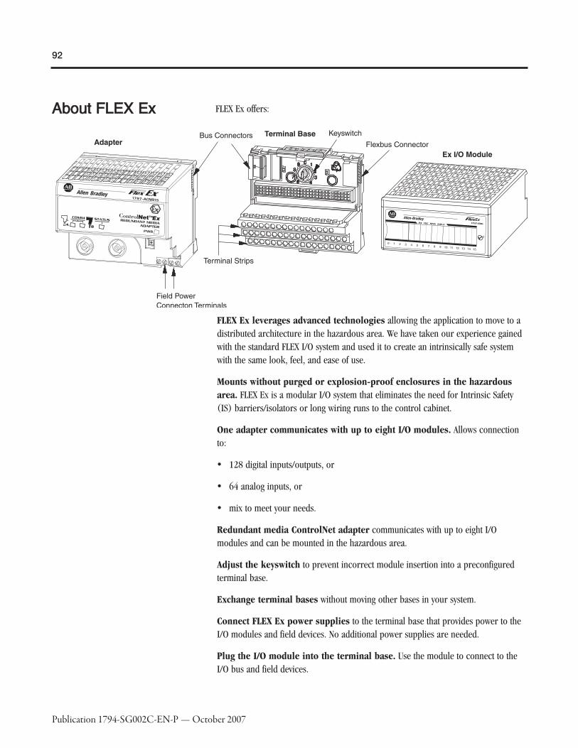
92
Publication 1794-SG002C-EN-P — October 2007
AAbboouutt FFLLEEXX EExx FLEX Ex offers:
FLEX Ex leverages advanced technologies allowing the application to move to adistributed architecture in the hazardous area. We have taken our experience gainedwith the standard FLEX I/O system and used it to create an intrinsically safe systemwith the same look, feel, and ease of use.
Mounts without purged or explosion-proof enclosures in the hazardousarea. FLEX Ex is a modular I/O system that eliminates the need for Intrinsic Safety(IS) barriers/isolators or long wiring runs to the control cabinet.
One adapter communicates with up to eight I/O modules. Allows connectionto:
� 128 digital inputs/outputs, or
� 64 analog inputs, or
� mix to meet your needs.
Redundant media ControlNet adapter communicates with up to eight I/Omodules and can be mounted in the hazardous area.
Adjust the keyswitch to prevent incorrect module insertion into a preconfiguredterminal base.
Exchange terminal bases without moving other bases in your system.
Connect FLEX Ex power supplies to the terminal base that provides power to theI/O modules and field devices. No additional power supplies are needed.
Plug the I/O module into the terminal base. Use the module to connect to theI/O bus and field devices.

93
Publication 1794-SG002C-EN-P — October 2007
Remove and insert modules under power. No direct wiring to the moduleenables you to change modules without disturbing field wiring or system power.
Mix and match I/O modules. Wide variety of digital, analog, temperature,frequency, and HART modules.
FLEXbus Isolator allows connection to standard FLEX I/O adapters and I/O thusproviding a choice of other networks.
Conformal coating on all modules meets the noxious gas requirement of ISA-S71.04-1985 severity level G3 for hydrogen sulfide, sulfur dioxide, chlorine, nitrogendioxide, hydrogen flouride, ammonia, and ozone.
FLEX Ex combines a terminal strip and intrinsic-safety isolation with an I/O interface.Use the terminal strip on the terminal base to wire your field devices directly. TheFLEX Ex design also offers these features:
� modularity for distributed IS systems
� all of the features of a larger, rack-based system
� installation near the field devices to reduce wiring costs and complexity
� terminations for field wiring eliminating the need for marshalling or extra terminalstrips
� ControlNet-based networking solution in the hazardous area with ControlNet Exproducts
� DIN-rail mounting
FLEX Ex provides additional value if system problems develop. The terminal base letsyou remove and insert I/O modules under power without rewiring or disrupting yoursystem. Combining your field-wiring terminations, IS isolation, and the I/O interfaceinto the same location saves you time, money, and makes your system easier tomaintain and troubleshoot. Additional benefits include:
� galvanic isolation between the I/O backplane, input circuitry, and power supply
� dual-fault protection IS circuits provide the highest fault tolerance
� I/O circuitry provides full IS field-device protection
� the modules themselves are IS protected for installation in hazardous environments
FLEX Ex modules may be removed and inserted while operating under power. Networkmodule maintenance and cable connections can be made in the hazardous area whilethe system is in operation and the area is hazardous.

94
Publication 1794-SG002C-EN-P — October 2007
TTyyppiiccaallCCoonnffiigguurraattiioonnss
The following are typical configurations of FLEX Ex I/O in an intrinsically safesystem:
� FLEX Ex I/O modules are interfaced through a ControlNet Ex I/O adapter module toa coax ControlNet segment that is confined to the hazardous area. This coaxControlNet Ex segment is interfaced through a ControlNet Ex coax drop repeatermodule and ControlNet Ex fiber media port adapter to a fiber-optic ControlNetsegment, which is fed through from the safe area. A FLEX Ex power supply powersthe repeater module, fiber media port adapter, ControlNet Ex I/O adapter module,and I/O modules individually. This configuration is best for long distances and alarge number of nodes.
� The FLEX Ex ControlNet barrier allows connection to a ControlNet Ex I/O adaptermodule in the hazardous area via coax directly from the safe area. The barrier ismounted in the safe area. This is more economical for intermediate distances andnodes.
� Sensors and actuators in a hazardous area can be connected to FLEX Ex I/Omodules, which are connected through a bus isolator module and connector to aFLEX I/O adapter in a safe area thus allowing connectivity to DeviceNet, ControlNet,Universal Remote I/O, and EtherNet/IP. This configuration may be most economicalfor low-point applications or when networks other than ControlNet are required.
� FLEX Ex I/O modules in a hazardous area can be connected through an extendercable to a FLEXBus feed-through connector in an explosion-proof enclosure. Insidethe enclosure, the feed-through connector is connected through a FLEX Ex extendercable, and then a bus isolator module and connector, to a FLEX I/O adapter.

95
Publication 1794-SG002C-EN-P — October 2007

96
Publication 1794-SG002C-EN-P — October 2007
EEnnttiittyy--BBaasseeddAArrcchhiitteeccttuurree
Entity parameters provide a system of quantifying and matching safe levels for voltage,current, inductance, and capacitance when connecting intrinsically safe field devicesand system devices together.
Configuration of the FLEX Ex system is based on the entity parameter method. Usingentity parameters allows high system flexibility in matching field and system devices.This provides maximum utility to the IS system designer and installer. For moreinformation, refer to the FLEX Ex System Certification Reference Manual, publication1797-6.5.6.
HHaazzaarrddoouuss AArreeaaDDeessiiggnnaattiioonn
A hazardous area is designated as any location in which a combustible material is ormay be present in the atmosphere in sufficient concentration to produce an ignitablemixture.
The North American method identifies these areas by Class, Division, and Group whilethe IEC (CENELEC) designates these areas by Zone and Gas Group.
Recently, North America has adopted the Zone method of identifying hazardouslocations as an option to the Division method.
CCllaassss DDeessiiggnnaattiioonn
Class identifies the type of hazardous atmosphere.
Class I Gas or vapor
Class II Dust
Class III Fiber or flying (no group designation)
DDiivviissiioonn//ZZoonnee DDeessiiggnnaattiioonnss
Division/Zone identifies the likelihood of a hazardous atmosphere being present.
Division Method (NorthAmerica) IEC Standard Zone Method
Ignitable mixture present continuously (long periods)Division 1
Zone 0 (Zone 20-Dust)
Ignitable mixture present intermittently Zone 1 (Zone 21-Dust)
Ignitable mixture is not normally present Division 2 Zone 2 (Zone 22-Dust)

97
Publication 1794-SG002C-EN-P — October 2007
GGaass//DDuusstt GGrroouuppss
Hazardous locations are grouped according to their ignition properties.
TypicalGas North American Gas Group IEC Gas GroupAcetylene A
IICHydrogen B
Ethylene C IIB
Propane D IIA
Methane✶ D✶ I
Metal Dust E
⎯Coal Dust F
Grain Dust G
✶Mining applications under jurisdiction of MSHA.
Use in North American Hazardous Locations
FLEX Ex modules are rated for installation in Class I Division 1 & 2, Groups A-Dhazardous areas. They are also rated to connect to field devices that are located inClass I, II, or III, Groups A-G hazardous areas.
If FLEX Ex components are to be installed in a Class II or III location in yourapplication, you must mount them in a suitable, dust-proof enclosure with theappropriate connectors, glans, and seals. For example, a NEMA 9 enclosure may beappropriate. The FLEX Ex modules are rated to connect to devices located in Class IIor III locations.
FLEX Ex modules are rated for installation in North American Class I Zone 1 & 2,Groups IIC, IIB, & IIA hazardous areas. They are also rated to connect to field devicesthat are located in North American Class I Zone 0, 1, & 2, Groups IIC, IIB, & IIAhazardous areas.
As always, observe local code requirements when applying your FLEX Ex application.For more information, refer to the FLEX Ex System Certification Reference Manual,publication 1797-6.5.6.
Use in CENELEC Hazardous Locations
FLEX Ex modules are rated for installation in European Zones 1, 2 and 22. They arealso rated to connect to field devices that are located in European Zones 0, 1, 2, 21and 22 hazardous areas. The FLEX Ex power supplies (1797-PS1E and -PS2E2) arerated for use in Zone 1 and 22.
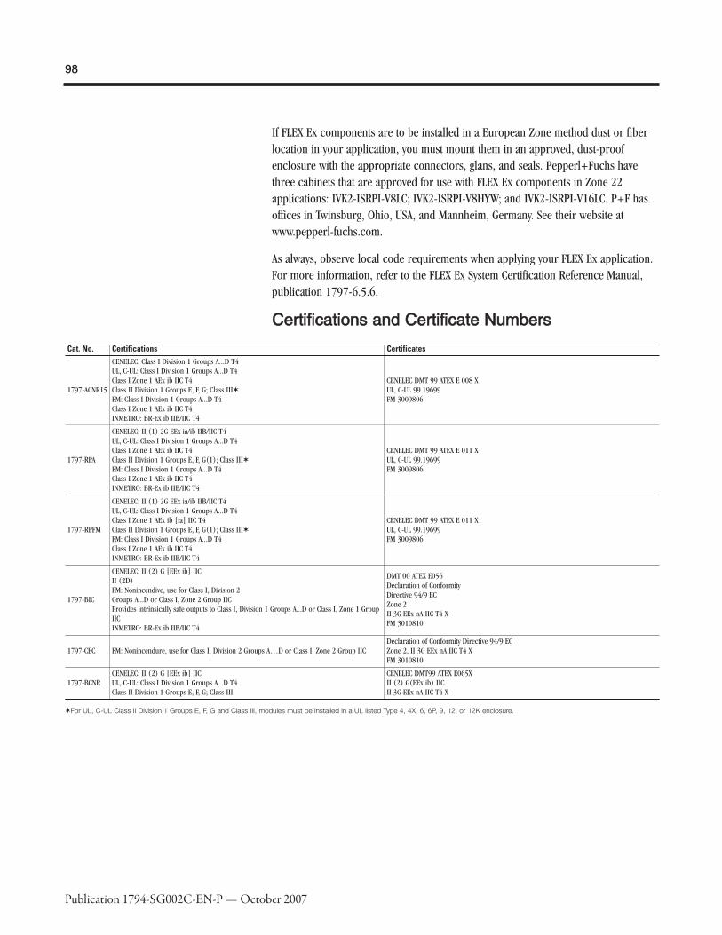
98
Publication 1794-SG002C-EN-P — October 2007
If FLEX Ex components are to be installed in a European Zone method dust or fiberlocation in your application, you must mount them in an approved, dust-proofenclosure with the appropriate connectors, glans, and seals. Pepperl+Fuchs havethree cabinets that are approved for use with FLEX Ex components in Zone 22applications: IVK2-ISRPI-V8LC; IVK2-ISRPI-V8HYW; and IVK2-ISRPI-V16LC. P+F hasoffices in Twinsburg, Ohio, USA, and Mannheim, Germany. See their website atwww.pepperl-fuchs.com.
As always, observe local code requirements when applying your FLEX Ex application.For more information, refer to the FLEX Ex System Certification Reference Manual,publication 1797-6.5.6.
CCeerrttiiffiiccaattiioonnss aanndd CCeerrttiiffiiccaattee NNuummbbeerrss
Cat. No. Certifications Certificates
1797-ACNR15
CENELEC: Class I Division 1 Groups A...D T4UL, C-UL: Class I Division 1 Groups A...D T4Class I Zone 1 AEx ib IIC T4Class II Division 1 Groups E, F, G; Class III✶FM: Class I Division 1 Groups A...D T4Class I Zone 1 AEx ib IIC T4INMETRO: BR-Ex ib IIB/IIC T4
CENELEC DMT 99 ATEX E 008 XUL, C-UL 99.19699FM 3009806
1797-RPA
CENELEC: II (1) 2G EEx ia/ib IIB/IIC T4UL, C-UL: Class I Division 1 Groups A...D T4Class I Zone 1 AEx ib IIC T4Class II Division 1 Groups E, F, G(1); Class III✶FM: Class I Division 1 Groups A...D T4Class I Zone 1 AEx ib IIC T4INMETRO: BR-Ex ib IIB/IIC T4
CENELEC DMT 99 ATEX E 011 XUL, C-UL 99.19699FM 3009806
1797-RPFM
CENELEC: II (1) 2G EEx ia/ib IIB/IIC T4UL, C-UL: Class I Division 1 Groups A...D T4Class I Zone 1 AEx ib [ia] IIC T4Class II Division 1 Groups E, F, G(1); Class III✶FM: Class I Division 1 Groups A...D T4Class I Zone 1 AEx ib IIC T4INMETRO: BR-Ex ib IIB/IIC T4
CENELEC DMT 99 ATEX E 011 XUL, C-UL 99.19699FM 3009806
1797-BIC
CENELEC: II (2) G [EEx ib] IICII (2D)FM: Nonincendive, use for Class I, Division 2Groups A...D or Class I, Zone 2 Group IICProvides intrinsically safe outputs to Class I, Division 1 Groups A...D or Class I, Zone 1 GroupIICINMETRO: BR-Ex ib IIB/IIC T4
DMT 00 ATEX E056Declaration of ConformityDirective 94/9 ECZone 2II 3G EEx nA IIC T4 XFM 3010810
1797-CEC FM: Nonincendure, use for Class I, Division 2 Groups A…D or Class I, Zone 2 Group IICDeclaration of Conformity Directive 94/9 ECZone 2, II 3G EEx nA IIC T4 XFM 3010810
1797-BCNRCENELEC: II (2) G [EEx ib] IICUL, C-UL: Class I Division 1 Groups A...D T4Class II Division 1 Groups E, F, G; Class III
CENELEC DMT99 ATEX E065XII (2) G(EEx ib) IICII 3G EEx nA IIC T4 X
✶For UL, C-UL Class II Division 1 Groups E, F, G and Class III, modules must be installed in a UL listed Type 4, 4X, 6, 6P, 9, 12, or 12K enclosure.

99
Publication 1794-SG002C-EN-P — October 2007
Cat. No. Certifications Certificates
1797-IBN16
CENELEC: II (1) 2G EEx ia/ib IIB/IIC T4II (1D) (2D)UL, C-UL: Class I Division 1 Groups A...D T4Class I Zone 1 AEx ib[ia] IIC T4Class II Division 1 Groups E, F, G(1); Class III✶FM: Class I Division 1 Groups A...D T4Class I Zone 1 AEx ib/[ia] IIC T4INMETRO: BR-Ex ib IIB/IIC T4
CENELEC DMT 98 ATEX E 013 XUL, C-UL 99.19699FM 3009806
1797-OB4D
CENELEC: II (1) 2G EEx ia/ib IIB/IIC T4II (1D) (2D)UL, C-UL: Class I Division 1 Groups A...D T4Class I Zone 1 AEx ib[ia] IIC T4Class II Division 1 Groups, E, F, G; Class IIIFM: Class I Division 1 Groups A...D T4Class I Zone 1 AEx ib/[ia] IIC T4INMETRO: BR-Ex ib IIB/IIC T4
CENELEC DMT 98 ATEX E 040 XUL, C-UL 99.19699FM 3009806
1797-IE8
CENELEC: II (1) 2G EEx ia/ib IIB/IIC T4II (1D) (2D)UL, C-UL: Class I Division 1 Groups A...D T4Class I Zone 1 AEx ib/[ia] IIC T4Class II Division 1 Groups E, F, G; Class IIIFM: Class I Division 1 Groups A...D T4Class I Zone 1 AEx ib/[ia] IIC T4INMETRO: BR-Ex ib IIB/IIC T4
CENELEC DMT 98 ATEX E 020 XUL, C-UL 99.19699, Class I Division 1 HazardousFM 3009806
1797-IE8H
CENELEC: II (1) 2G EEx ia/ib IIB/IIC T4II (1D) (2D)UL, C-UL: Class I Division 1 Groups A...D T4Class I Zone 1 AEx ib/[ia] IIC T4Class II Division 1 Groups E, F, G; Class IIIFM: Class I Division 1 Groups A...D T4Class I Zone 1 AEx ib/[ia] IIC T4
CENELEC DMT 98 ATEX E 020 XUL, C-UL 99.19699FM 3009806
1797-IE8NF
CENELEC: II (1) 2G EEx ia/ib IIB/IIC T4II (1D) (2D)UL, C-UL: Class I Division 1 Groups A...D T4Class I Zone 1 AEx ib/[ia] IIC T4Class II Division 1 Groups E, F, G; Class IIIFM: Class I Division 1 Groups A...D T4Class I Zone 1 AEx ib/[ia] IIC T4
CENELEC DMT 98 ATEX E 020 XUL, C-UL 99.19699, Class I Division 1 HazardousFM 3009806 1797-IE8NF
1797-IRT8
CENELEC: II (1) 2G EEx ia/ib IIB/IIC T4II (1D) (2D)UL, C-UL: Class I Division 1 Groups A...D T4Class I Zone 1 AEx ib/[ia] IIC T4Class II Division 1 Groups E, F, G; Class IIIFM: Class I Division 1 Groups A...D T4Class I Zone 1 AEx ib/[ia] IIC T4INMETRO: BR-Ex ib IIB/IIC T4
CENELEC DMT 98 ATEX E 023 XUL, C-UL 99.19699FM 3009806
1797-OE8
CENELEC: II (1) 2G EEx ia/ib IIB/IIC T4II (1D) (2D)UL, C-UL: Class I Division 1 Groups A...D T4Class I Zone 1 AEx ib/[ia] IIC T4Class II Division 1 Groups E, F, G; Class IIIFM: Class I Division 1 Groups A...D T4Class I Zone 1 AEx ib/[ia] IIC T4INMETRO: BR-Ex ib IIB/IIC T4
CENELEC DMT 00 ATEX E 042 XUL, C-UL 99.19699, Class I Division 1 HazardousFM 3009806
1797-OE8H CENELEC: II (1) 2G EEx ia/ib IIB/IIC T4, II (1D)(2D)
CENELEC: II (1) 2G EEx ia/ib IIB/IIC T4II (1D) (2D)UL, C-UL: Class I Division 1 Groups A...D T4Class I Zone 1 AEx ib/[ia] IIC T4Class II Division 1 Groups E, F, G; Class IIIFM: Class I Division 1 Groups A...D T4Class I Zone 1 AEx ib/[ia] IIC T4
1797-IJ2
CENELEC: II (1) 2G EEx ia/ib IIB/IIC T4II (1D) (2D)UL, C-UL: Class I Division 1 Groups A...D T4Class I Zone 1 AEx ib/[ia] IIC T4Class II Division 1 Groups E, F, G; Class IIIFM: Class I Division 1 Groups A...D T4Class I Zone 1 AEx ib/[ia] IIC T4INMETRO: BR-Ex ib IIB/IIC T4
CENELEC DMT 98 ATEX E 033 XUL, C-UL 99.19699FM 3009806
✶For UL, C-UL Class II Division 1 Groups E, F, G and Class III, modules must be installed in a UL listed Type 4, 4X, 6, 6P, 9, 12, or 12K enclosure.

100
Publication 1794-SG002C-EN-P — October 2007
Cat. No. Certifications Certificates
1797-TB3
CENELEC: II 2G EEx ia IIC T4UL, C-UL: Class I Division 1 & 2 Groups A...D T4Class I Zone 1 & 2 AEx ia IIC T4Class II Division 1 Groups E, F, G; Class III✶FM: Class I Division 1 Groups A...D T4Class I Zone 1 AEx ib [ia] IIC T4INMETRO: BR-Ex ib IIB/IIC T4
CENELEC DMT 98ATEX E 012 XUL, C-UL 99.19699FM 3009806
1797-TB3S
CENELEC: II 2G EEx ia IIC T4UL, C-UL: Class I Division 1 & 2 Groups A...D T4Class I Zone 1 & 2 AEx ia IIC T4Class II Division 1 Groups E, F, G; Class III✶FM: Class I Division 1 Groups A...D T4Class I Zone 1 AEx ib [ia] IIC T4INMETRO: BR-Ex ib IIB/IIC T4
CENELEC DMT 98 ATEX E 012 XUL, C-UL 99.19699FM 3009806
1797-PS1N
UL, C-UL: Class I Division 1 Groups A...DClass II Division 1 Groups E, F, G; Class IIIFM: Mounting - Class I Division 1 Groups B...D T4IS Power - Class I Division 1 Groups A...D T4Class I Zone 1 AEx [ib] IIC
UL, C-ULUL File Number E197983C-UL-US
1797-PS1E
CENELEC: Series A - EEx de [ib] IIC T4Series B - II 2G EEx de [ib] IIC T4II 3D IP54 T90 °CINMETRO: BR-Ex ib IIB/IIC T4
—
1797-PS2N2
UL, C-UL: Class I Division 1 Groups B…D T4Class I Division 2 Groups A…D T4FM: Mounting - Class I Division 1Groups B…D T4, Class I Division 2,Groups A…D, T4, Class I Zone 1 IICIS Power - Class I Division 1&2Groups A…G T4Class I Zone 1 AEx [ib] IIC
UL, C-UL 99.19699FM 3009806
1797-PS2E2CENELEC: II 2G EEx de [ib] IIC T4II 3D IP54 T90 °CINMETRO: BR-Ex ib IIB/IIC T4
BVS 98.D.2055X
✶For UL, C-UL Class II Division 1 Groups E, F, G and Class III, modules must be installed in a UL listed Type 4, 4X, 6, 6P, 9, or 12K enclosure.
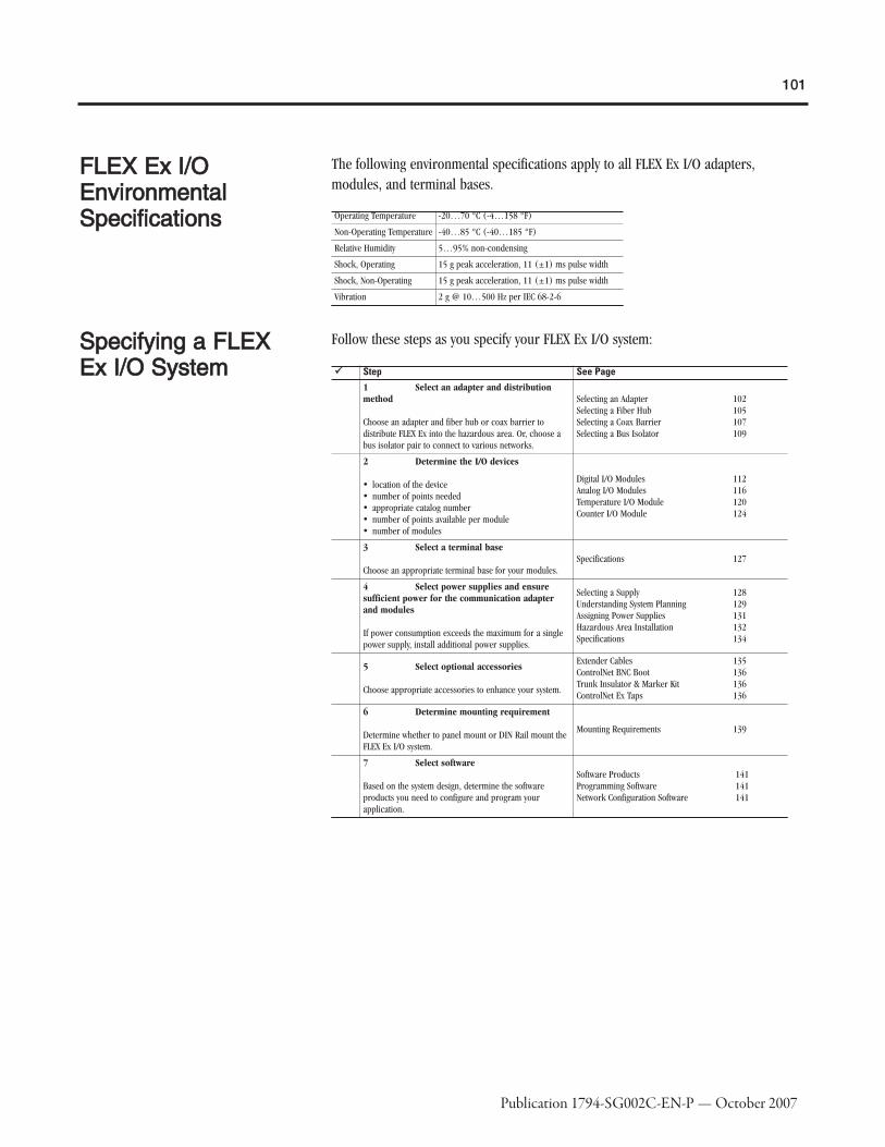
101
Publication 1794-SG002C-EN-P — October 2007
FFLLEEXX EExx II//OOEEnnvviirroonnmmeennttaallSSppeecciiffiiccaattiioonnss
The following environmental specifications apply to all FLEX Ex I/O adapters,modules, and terminal bases.
Operating Temperature -20…70 °C (-4…158 °F)
Non-Operating Temperature -40…85 °C (-40…185 °F)
Relative Humidity 5…95% non-condensing
Shock, Operating 15 g peak acceleration, 11 (±1) ms pulse width
Shock, Non-Operating 15 g peak acceleration, 11 (±1) ms pulse width
Vibration 2 g @ 10…500 Hz per IEC 68-2-6
SSppeecciiffyyiinngg aa FFLLEEXXEExx II//OO SSyysstteemm
Follow these steps as you specify your FLEX Ex I/O system:
�� Step See Page1 Select an adapter and distributionmethod
Choose an adapter and fiber hub or coax barrier todistribute FLEX Ex into the hazardous area. Or, choose abus isolator pair to connect to various networks.
Selecting an Adapter 102Selecting a Fiber Hub 105Selecting a Coax Barrier 107Selecting a Bus Isolator 109
2 Determine the I/O devices
� location of the device� number of points needed� appropriate catalog number� number of points available per module� number of modules
Digital I/O Modules 112Analog I/O Modules 116Temperature I/O Module 120Counter I/O Module 124
3 Select a terminal base
Choose an appropriate terminal base for your modules.Specifications 127
4 Select power supplies and ensuresufficient power for the communication adapterand modules
If power consumption exceeds the maximum for a singlepower supply, install additional power supplies.
Selecting a Supply 128Understanding System Planning 129Assigning Power Supplies 131Hazardous Area Installation 132Specifications 134
5 Select optional accessories
Choose appropriate accessories to enhance your system.
Extender Cables 135ControlNet BNC Boot 136Trunk Insulator & Marker Kit 136ControlNet Ex Taps 136
6 Determine mounting requirement
Determine whether to panel mount or DIN Rail mount theFLEX Ex I/O system.
Mounting Requirements 139
7 Select software
Based on the system design, determine the softwareproducts you need to configure and program yourapplication.
Software Products 141Programming Software 141Network Configuration Software 141
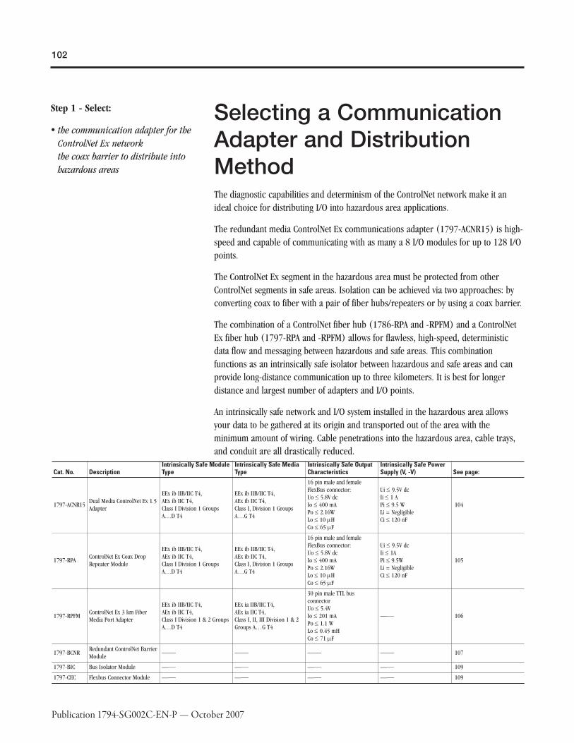
102
Publication 1794-SG002C-EN-P — October 2007
Step 1 - Select:
� the communication adapter for theControlNet Ex networkthe coax barrier to distribute intohazardous areas
Selecting a CommunicationAdapter and DistributionMethodThe diagnostic capabilities and determinism of the ControlNet network make it anideal choice for distributing I/O into hazardous area applications.
The redundant media ControlNet Ex communications adapter (1797-ACNR15) is high-speed and capable of communicating with as many a 8 I/O modules for up to 128 I/Opoints.
The ControlNet Ex segment in the hazardous area must be protected from otherControlNet segments in safe areas. Isolation can be achieved via two approaches: byconverting coax to fiber with a pair of fiber hubs/repeaters or by using a coax barrier.
The combination of a ControlNet fiber hub (1786-RPA and -RPFM) and a ControlNetEx fiber hub (1797-RPA and -RPFM) allows for flawless, high-speed, deterministicdata flow and messaging between hazardous and safe areas. This combinationfunctions as an intrinsically safe isolator between hazardous and safe areas and canprovide long-distance communication up to three kilometers. It is best for longerdistance and largest number of adapters and I/O points.
An intrinsically safe network and I/O system installed in the hazardous area allowsyour data to be gathered at its origin and transported out of the area with theminimum amount of wiring. Cable penetrations into the hazardous area, cable trays,and conduit are all drastically reduced.
Cat. No. DescriptionIntrinsically Safe ModuleType
Intrinsically Safe MediaType
Intrinsically Safe OutputCharacteristics
Intrinsically Safe PowerSupply (V, -V) See page:
1797-ACNR15Dual Media ControlNet Ex 1.5Adapter
EEx ib IIB/IIC T4,AEx ib IIC T4,Class I Division 1 GroupsA…D T4
EEx ib IIB/IIC T4,AEx ib IIC T4,Class I, Division 1 GroupsA…G T4
16 pin male and femaleFlexBus connector:Uo ≤ 5.8V dcIo ≤ 400 mAPo ≤ 2.16WLo ≤ 10 μHCo ≤ 65 μF
Ui ≤ 9.5V dcIi ≤ 1 APi ≤ 9.5 WLi = NegligibleCi ≤ 120 nF
104
1797-RPAControlNet Ex Coax DropRepeater Module
EEx ib IIB/IIC T4,AEx ib IIC T4,Class I Division 1 GroupsA…D T4
EEx ib IIB/IIC T4,AEx ib IIC T4,Class I, Division 1 GroupsA…G T4
16 pin male and femaleFlexBus connector:Uo ≤ 5.8V dcIo ≤ 400 mAPo ≤ 2.16WLo ≤ 10 μHCo ≤ 65 μF
Ui ≤ 9.5V dcIi ≤ 1APi ≤ 9.5WLi = NegligibleCi ≤ 120 nF
105
1797-RPFMControlNet Ex 3 km FiberMedia Port Adapter
EEx ib IIB/IIC T4,AEx ib IIC T4,Class I Division 1 & 2 GroupsA…D T4
EEx ia IIB/IIC T4,AEx ia IIC T4,Class I, II, III Division 1 & 2Groups A…G T4
30 pin male TTL busconnectorUo ≤ 5.4VIo ≤ 201 mAPo ≤ 1.1 WLo ≤ 0.45 mHCo ≤ 71 μF
—⎯ 106
1797-BCNRRedundant ControlNet BarrierModule
—⎯ —⎯ —⎯ —⎯ 107
1797-BIC Bus Isolator Module —⎯ —⎯ —⎯ —⎯ 109
1797-CEC Flexbus Connector Module —⎯ —⎯ —⎯ —⎯ 109

103
Publication 1794-SG002C-EN-P — October 2007

104
Publication 1794-SG002C-EN-P — October 2007
11779977--AACCNNRR1155 DDuuaall MMeeddiiaa CCoonnttrroollNNeett EExx 11..55AAddaapptteerr
The 1797-ACNR15 interfaces FLEX Ex I/O modules to a coax segment of a ControlNetEx I/O link. It provides power to the backplane to run bus interface circuitry aboardI/O modules and is capable of dual ControlNet Ex cable media.
1797-ACNR15I/O Module Capacity 8
Communication Interface Quad-shield RG-6 coax
Communication Rate 5 Mbps
Noxious Gas Exposure Tested to severity level G3, ISA-S71.04-1985
Power Dissipation 8.5 W
Dimensions (HxWxD), Metric 94 x 94 x 91 mm
Dimensions (HxWxD), Imperial 3.7 x 3.7 x 3.58 in
Weight, Metric 0.2 kg
Thermal Dissipation 29 BTU/hr

105
Publication 1794-SG002C-EN-P — October 2007
11779977--RRPPAA CCoonnttrroollNNeett EExx CCooaaxx DDrroopp RReeppeeaatteerrMMoodduullee
The 1797-RPA functions as part of the fiber repeater hub within the hazardous area toextend the length of the ControlNet Ex segments to interlink systems all operatingwithin the area. It functions as the intelligent starter block for a multiport repeaterand is configured with at least one media adapter.
1797-RPAFiber Media Port Adapter Capacity 2
ControlNet Cable Quad-shield RG-6 coax
Communication Rate 5 Mbps
Noxious Gas Exposure Tested to severity level G3, ISA-S71.04-1985
Power Dissipation 8.5 W
Dimensions (HxWxD), Metric 94 x 94 x 91 mm
Dimensions (HxWxD), Imperial 3.7 x 3.7 x 3.58 in
Weight, Metric 0.2 kg
Thermal Dissipation 29 BTU/hr

106
Publication 1794-SG002C-EN-P — October 2007
11779977--RRPPFFMM CCoonnttrroollNNeett EExx 33 kkmm FFiibbeerr MMeeddiiaa PPoorrttAAddaapptteerr
The 1797-RPFM (part of the fiber repeater hub) functions as a non-intelligent fiber tobackplane conversion device and converts glass fiber infrared LED media signals tobackplane signals for use by the 1797-RPA repeater module.
1797-RPFMCommunication Interface Fiber optic cable
Fiber Type 62.5/125 mm
Fiber Termination Type ST (plastic or ceramic)
Communication Rate 5 Mbps
Noxious Gas ExposureTested to severity level G3,ISA-S71.04-1985
Power Dissipation Included in 1797-RPA
Dimensions (HxWxD), Metric 94 x 94 x 91 mm
Dimensions (HxWxD), Imperial 3.7 x 3.7 x 3.58 in
Weight, Metric 0.1 kg
Thermal Dissipation Included in 1797-RPA

107
Publication 1794-SG002C-EN-P — October 2007
11779977--BBCCNNRR CCooaaxx BBaarrrriieerr MMoodduullee
The redundant media ControlNet coax barrier (1797-BCNR) isolates the ControlNetsegment in the safe area from that in the hazardous area. It allows connection into thehazardous area without converting to/from fiber media. The barrier can support up to20 adapters and distances up to 500 meters. Thus, it addresses intermediate sizeapplications in a highly cost-effective manner. The barrier can be mounted in safe,Division 2 or Zone 2 areas.
When using a 1797-BCNR, the total allowable length of a segment containing standardRG-6 quad-shield cable depends on the number of taps in your segment. There is nominimum trunk-cable section length requirement. The maximum allowable length of asegment that contains a 1797-BCNR is 500m (1640 ft) with two taps connected. Eachadditional tap decreases the maximum length of the segment according to the chart.The maximum number of taps allowed on a segment is 20 with a maximum length of250m (820 ft).

108
Publication 1794-SG002C-EN-P — October 2007
1797-BCNR
ControlNet Ex System CharacteristicsUo = 7 VIo = 55 mA @ 52 KHzPo = negligible
Non Ex ControlNet Characteristics
Un = 5VUm = 253V acI = not definedP = not defined
ControlNet Communication Rate 5 M bit/s5 Mbps
Transmission Attenuation -7.84 dB
Noxious Gas Exposure —
Dimensions (HxWxD), Metric 7 x 10 x 9 cm
Dimensions (HxWxD), Imperial 2.76 x 3.94 x 3.55 in
Weight, Metric 200 g
IS Module Type EEx [ib] IIC

109
Publication 1794-SG002C-EN-P — October 2007
11779977--BBIICC BBuuss IIssoollaattoorr MMoodduullee aanndd 11779977--CCEECCFFlleexxbbuuss CCoonnnneeccttoorr
The bus isolator modules, 1797-BIC and -CEC, allow you to configure FLEX Exmodules and FLEX I/O modules on the DIN Rail when attached to the same adapterand grouped together on appropriate sides of the bus isolator module. This highlyflexible, cost-effective solution combines intrinsically safe and non-intrinsically safesystems.
Intermixed system can be configured for use in the:
� safe area much like traditional IS and I/O systems
� hazardous and safe control equipment where the distance of physical separation isshort
� FLEX Ex I/O with communication adapters that are not intrinsically safe
� for use with FlexLogix on its local rail, however cannot be used with the 1794-FLAadapter (secondary rail)

110
Publication 1794-SG002C-EN-P — October 2007
The 1797-BIC and -CEC modules provide an IS-compatible mechanism to separate twosections of the backplane, allowing IS and non-IS field-device wiring to the same I/Ogroup. It converts hazardous power to IS-safe power to run one side of the busreceiver/transmitter circuitry and IS-safe power to slave side modules. A total of eightI/O modules (1794 FLEX or 1797 FLEX Ex) may be attached to the adapter.
When combining 1794 FLEX and 1797 FLEX Ex I/O, the 1794 FLEX I/O modules areplaced to the left of the 1797-BIC and -CEC modules while the 1797 FLEX Ex I/Omodules are placed on the right.
� IMPORTANT: A FLEX Ex power supply (1797-PSxxx)must be used to power the 1797 FLEX Ex I/O regard-less of where they are located.

111
Publication 1794-SG002C-EN-P — October 2007
1797-BICI/O Module Capacity 8✶
Isolation Voltage System to System and System Slave Side to Power Supply: Galvanic to DIN EN 50020
Power Consumption, Max. 0.15 A @ 18…32V dc
Power Source Failure, Maximum Input Um = 253V ac
Noxious Gas Exposure Tested to severity level G3, ISA-S71.04-1985
Power Dissipation 2.1 W
Thermal Dissipation 7.2 BTU/hr
Dimensions (HxWxD), Metric 87 x 94 x 75 mm
Dimensions (HxWxD), Imperial 3.4 x 3.7 x 2.95 in
Weight, Metric 0.2 kg
IS Module Type [EEx ib] IIC
✶8 FLEX Ex modules. Note that a total of eight I/O modules can be attached to a 1794 FLEX I/O adapter. The 1797-BIC and1797-CEC are not included in this number. In intermixed systems, the number of 1797 FLEX Ex I/O modules (attached ontothe 1797-BIC) plus the number of 1794 FLEX I/O modules (connected between the adapter and the 1797-CEC) cannotexceed eight.
Use the optional Bus Isolator 1797-CE1S (0.3m, 1 ft) or 1797-CE3S (0.9m, 3 ft)extender cable to mix systems in the hazardous area within a purged or explosion-proof enclosure.
FFLLEEXXBBuuss FFeeeedd TThhrroouugghhss
For Metric Threads on the Connector
Part Number ManufacturerRS-FEED.M Pepperl+Fuchs
For NPT Threads on the Connector
Part Number ManufacturerRS-FEED.NPT Pepperl+Fuchs
Agency CertificationCENELEC: EEx d IIC T6IBEx U 98 ATEX 1033UFM: Approved per J.I. 3002937
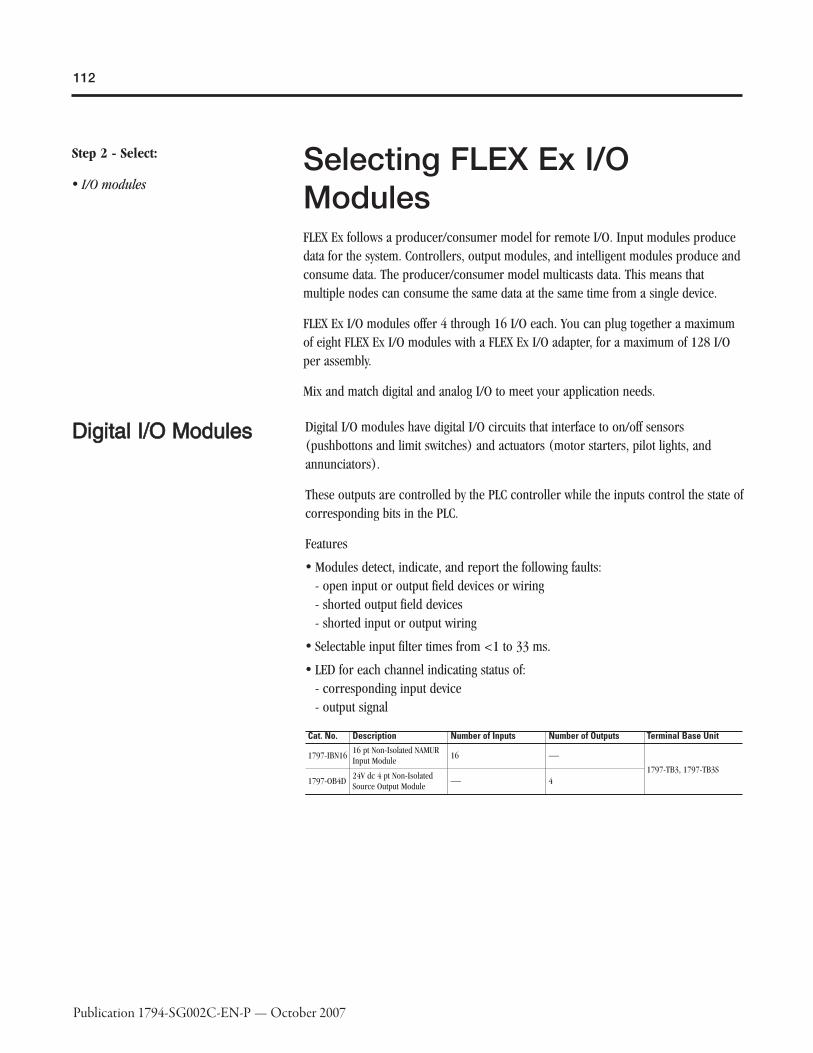
112
Publication 1794-SG002C-EN-P — October 2007
Step 2 - Select:
� I/O modulesSelecting FLEX Ex I/OModulesFLEX Ex follows a producer/consumer model for remote I/O. Input modules producedata for the system. Controllers, output modules, and intelligent modules produce andconsume data. The producer/consumer model multicasts data. This means thatmultiple nodes can consume the same data at the same time from a single device.
FLEX Ex I/O modules offer 4 through 16 I/O each. You can plug together a maximumof eight FLEX Ex I/O modules with a FLEX Ex I/O adapter, for a maximum of 128 I/Oper assembly.
Mix and match digital and analog I/O to meet your application needs.
DDiiggiittaall II//OO MMoodduulleess Digital I/O modules have digital I/O circuits that interface to on/off sensors(pushbottons and limit switches) and actuators (motor starters, pilot lights, andannunciators).
These outputs are controlled by the PLC controller while the inputs control the state ofcorresponding bits in the PLC.
Features
� Modules detect, indicate, and report the following faults:- open input or output field devices or wiring- shorted output field devices- shorted input or output wiring
� Selectable input filter times from <1 to 33 ms.
� LED for each channel indicating status of:- corresponding input device- output signal
Cat. No. Description Number of Inputs Number of Outputs Terminal Base Unit
1797-IBN1616 pt Non-Isolated NAMURInput Module
16 ⎯1797-TB3, 1797-TB3S
1797-OB4D24V dc 4 pt Non-IsolatedSource Output Module
⎯ 4

113
Publication 1794-SG002C-EN-P — October 2007
11779977--IIBBNN1166 1166 pptt NNoonn--IIssoollaatteedd NNAAMMUURR IInnppuuttMMoodduullee
� Fault detection, fault bits in data table and LED (per channel) blinking red (1 Hz)
� Lead brekage defeat on four-channel group basis via module DIP switch selection
� Fault detection can be disabled via data table
� Programmable digital input filtering 1...33 ms (OFF to ON and ON to OFF)
� All modules updated to flexbus ≤ 500 μs
� Compatible with NAMUR sensors and dry contacts
1797-IBN16Number of Inputs 16
Input Type DIN19234, NAMUR compatible
Current, On-State Input, Min. 2.1 mA
Current, Off-State Input, Max. 1.2 mA
Hysteresis 0.2 mA
Input Frequency, Max. 1000 Hz
Input Pulse Width > 500 μs, on or off
Load Voltage, Max. U/V = 7.5V dc
Short Circuit Current 7.5 mA
Short Circuit Threshold Current > 6 mA
Lead Breakage Threshold Current < 0.35 mA
Input Delay Time, OFF to ON 1 ms, 2 ms, 3 ms, 5 ms, 9 ms, 17 ms, 33 ms✶
Input Delay Time, ON to OFF 1 ms, 2 ms, 3 ms, 5 ms, 9 ms, 17 ms, 33 ms�
Intrinsically Safe Input TypeEEx ia IIB/IIC T4, AEx ia IIC T4, Class I, II, III Division 1Groups A…G T4
Intrinsically Safe Input Characteristics
16 pin male and female FlexBus connector:Ui ≤ 5.8V dcIi ≤ 400 mALi = NegligibleCi = Negligible
Noxious Gas Exposure Tested to severity level G3, ISA-S71.04-1985
FLEX Ex Power Consumption (W) at 24V 2.8
Power Dissipation 2.8 W
Dimensions (HxWxD), Metric 46 x 94 x 75 mm
Dimensions (HxWxD), Imperial 1.8 x 3.7 x 2.95 in
Weight, Metric 0.2 kg
Thermal Dissipation, Max. 9.6 BTU/hr
✶1 ms default - selectable through output image table (see "Setting Input Filter Times").�1 ms default - selectable through output image table.

114
Publication 1794-SG002C-EN-P — October 2007
11779977--OOBB44DD 2244VV DDCC 44 pptt NNoonn--IIssoollaatteedd SSoouurrcceeOOuuttppuutt MMoodduullee
� 4 output channels referenced to a single supply
� Yellow LED to indicate output state, output ON = LED ON
� Fault indication, signal to the backplane and LED (per channel) blinking red forfault
� Output wire-off detection
� Output wire-off detection on per channel basis via module data bit
� Electronically short-circuit protected, fault reported to controller
� All channels updated from the backplane every 2 ms
� Output fault state programmable
1797-OB4DNumber of Outputs 4
Output Load Range 30…5000 Ω
Fault Detection Fault bits in data table and LED (per channel) blinking red (1 Hz)
Protection Lead break, overload, short circuit
Output Delay Time, OFF to ON, Max. ≤ 1.2 ms
Output Delay Time, ON to OFF, Max. ≤1.2 ms
Intrinsically Safe Output TypeEEx ia IIB/IIC T4,AEx ia IIC T4,Class I, II, III Division 1 & 2 Groups A…G T4
Intrinsically Safe Output Characteristics
16 pin male and female FlexBus connector:Ui ≤ 5.8V dcIi ≤ 400 mALi = NegligibleCi ≤ 1.35 μF
Noxious Gas Exposure Tested to severity level G3, ISA-S71.04-1985
FLEX Ex Power Consumption (W) at 24V 7.5
Power Dissipation 5 W
Dimensions (HxWxD), Metric 46 x 94 x 75 mm
Dimensions (HxWxD), Imperial 1.8 x 3.7 x 2.95 in
Weight, Metric 0.2 kg
Thermal Dissipation, Max. 17.07 BTU/hr

115
Publication 1794-SG002C-EN-P — October 2007
1797-OB4D Output Voltage/Current Capability

116
Publication 1794-SG002C-EN-P — October 2007
AAnnaalloogg II//OO MMoodduulleess Choose analog I/O modules when you need:
� Configurable channels allow the module to be used with a variety of sensors.
� On-board scaling eliminates the need to scale the data in the controller.Controller processing time and power are preserved for more important tasks, suchas I/O control, communications, or other user-driven functions.
� On-line configuration. Modules can be configured in the RUN mode using theprogramming software or the control program. This allows you to changeconfiguration while the system is operating. For example, the input filter for aparticular channel could be changed, or a channel could be disabled based on abatch condition.
� Over- and under-range detections and indications eliminates the need to testvalues in the control program, saving valuable processing power of the controller.In addition, since alarms are handled by the module, the response is faster and onlya single bit needs to be monitored to determine if an error condition has occurred.
� Ability to direct output device operation during an abnormal condition.Each channel of the output module can be individually configured to hold its lastvalue or assume a user-defined value on either a run-to-program or run-to-faultcondition. This feature allows you to set the condition of your analog devices, andtherefore your control process, which may help to ensure a reliable shutdown.
� Selectable input filters allows you to select from several different filterfrequencies for each channel that best meets the performance needs of yourapplication based on environmental limitations. Lower filter settings provide greaternoise rejection and resolution. Higher filter settings provide faster performance.
� Selectable response to broken input sensor. This feature provides feedback tothe controller that a field device is not connected or operating properly. This allowsyou to specify corrective action based on the bit or channel condition.
Cat. No. Description Number of Inputs Number of Outputs Terminal Base Unit
1797-IE88 pt 16 bit Single-EndedNon-Isolated Analog InputModule
8 ⎯
1797-TB3, 1797-TB3S
1797-IE8H8 pt 16 bit Single-EndedNon-Isolated Analog InputModule with HART capability
1797-IE8NF8 pt 16 bit Single-EndedNon-Isolated Analog InputModule with Noise Filter
1797-IRT88 pt 16 bit Non-Isolated RTDThermocouple/mV InputModule
1797-OE88 pt 13 bit Single-EndedNon-Isolated Analog OutputModule
⎯ 8
1797-OE8H8 pt 16 bit Single-EndedNon-Isolated Analog InputModule with HART capability

117
Publication 1794-SG002C-EN-P — October 2007
FFLLEEXX EExx II//OO AAnnaallooggIInnppuutt MMoodduulleess
11779977--IIEE88,, --IIEE88HH ((HHAARRTT)),, aanndd --IIEE88NNFF ((WWiitthh NNooiisseeFFiilltteerr)) 88 pptt 1166 BBiitt SSiinnggllee--EEnnddeedd NNoonn--IIssoollaatteedd AAnnaallooggIInnppuutt MMoodduulleess
� Eight single-ended input channels referenced to a single common
� 3-wire input for 2- and 3-wire transmitters
� Functional data: normal inputinput current = 4...20 mA, full-current range0...22 mA to allow for over and underrange indication
� Wire-off detection, signal to the backplane and LED (per channel) blinking red forfault
� Wire-off detection on per channel basis via module data bits
� Input filter cutoff programmable
� Resolution: 16 bits
� Accuracy: 0.1%
� The 1797-IE8 is typically used to act on change-of-state and high-speed applications.It is not compatible with HART handheld devices.
� The 1797-IE8NF has additional hardware filtering that damps out spurious signalsand can be used for slower changing, steady-state processes. It has slower samplingthan the 1797-IE8 (100 ms versus 1 ms). It is compatible with HART handhelddevices.
� The 1797-IE8H is similar to the 1797-IE8NF with real time data table updates. Italso supports pass-through of HART commands as unscheduled ControlNetmessages. It is compatible with FDT software packages.

118
Publication 1794-SG002C-EN-P — October 2007
1797-IE8 1797-IE8H 1797-IE8NFInput Resolution 16 bits 16 bits 16 bits
Input Signal Range 0…20 mA 0…20 mA 0…20 mA
Transfer Characteristics, Accuracy 0.1% of output signal range at 20 °C (68 °F) 0.1% of output signal range at 20 °C (68 °F) 0.1% of output signal range at 20 °C (68 °F)
Transfer Characteristics, Temperature Drift 0.005%/°C of output signal range 0.05%/°C of output signal range 0.005%/°C of output signal range
Functional Data Range> 15V @ 22 mA> 21.5V @ 0 mA
> 17V @ 22 mA> 23V @ 0 mA
> 15V @ 22 mA> 21.5V @ 0 mA
Data Format Configurable Configurable Configurable
Step Response to 99% of Full Scale 4 ms 80 ms 80 ms
Update Time, Module from Adapter 200…1600 μs 200…1600 μs 200…1600 μs
Noxious Gas Exposure Tested to severity level G3, ISA-S71.04-1985 Tested to severity level G3, ISA-S71.04-1985 Tested to severity level G3, ISA-S71.04-1985
FLEX Ex Power Consumption (W) at 24V 7.5 7.1 7.5
Power Dissipation 5.2 W 5.2 W 5.2 W
Thermal Dissipation, Max. 17.75 BTU/hr 17.75 BTU/hr 17.75 BTU/hr
Dimensions (HxWxD), Metric 46 x 94 x 75 mm 46 x 94 x 75 mm 46 x 94 x 75 mm
Dimensions (HxWxD), Imperial 1.8 x 3.7 x 2.95 in 1.8 x 3.7 x 2.95 in 1.8 x 3.7 x 2.95 in
Weight, Metric 0.2 kg 0.2 kg 0.2 kg
Intrinsically Safe Input Type
Uo ≤ 23.7VIo ≤ 93.5 mAPo ≤ 555 mWEEx ia IIB/IIC (CENELEC)AEx ia IIC (US)Ex ia IIC (Canada)Class I, Zone 0, Groups IIC, IIB, IIAClass I, Division 1, Groups A, B, C, DClass II, Division 1, Groups E, F, GClass III, Division 1
Uo ≤ 24.4VIo ≤ 92.5 mAPo ≤ 565 mWEEx ia IIB/IIC T4
Uo ≤ 23.7VIo ≤ 93.5 mAPo ≤ 555 mWEEx ia IIB/IIC (CENELEC)AEx ia IIC (US)Ex ia IIC (Canada)Class I, Zone 0, Groups IIC, IIB, IIAClass I, Division 1, Groups A, B, C, DClass II, Division 1, Groups E, F, GClass III, Division 11
Intrinsically Safe Input Characteristics
16 pin male and female FlexBus connector:Ui ≤ 5.8V dcIi ≤ 400 mALi = NegligibleCi ≤ 1.35 μF
16 pin male and female FlexBus connector:Ui ≤ 5.8V dcIi ≤ 400 mALi = NegligibleCi ≤ 1.35 μF
16 pin male and female FlexBus connector:Ui ≤ 5.8V dcIi ≤ 400 mALi = NegligibleCi ≤ 1.35 μF
119
Publication 1794-SG002C-EN-P — October 2007
HHAARRTT IInntteerrffaaccee MMoodduulleess FLEX and FLEX Ex HART analog modules (IE8H and OE8H) are ideal for use inapplications that need connection with FDT (Field Device Tool) compatible assetmanagement software, such as Rockwell Software FieldCare HART Communicationbundle or Endress + Hauser Fieldcare. For HART Device Type Management (DTM)programs and drivers, go to http://www.ab.com/io, and select Configurations Files,DTM files for HART.
� FLEX HART analog modules can be used on ControlNet or EtherNet/IP. The FLEXEthernet adapter requires firmware v3.1 or later, which is flash upgradeable, tosupport these modules.
� Each HART field device is wired to its own input or output channel:� 8 single-ended channels
does not support multi-drop2 or 3 wire devices
� For use with FlexLogix, the modules must be used on a distributed rail with aControlNet adapter and not on a local rail.
� HART commands cand be transmitted by unscheduled message:� sample RLL subroutines are available.
currently limited to one instance of RLL subroutine per module, one channel at atime.

120
Publication 1794-SG002C-EN-P — October 2007
11779977--IIRRTT88 88 pptt 1166 BBiitt NNoonn--IIssoollaatteedd RRTTDDTThheerrmmooccoouuppllee//mmVV IInnppuutt MMoodduullee
� input channels referenced to a single common
� RTD mode⎯ 2-, 3-, and 4-wire connection⎯ sensor lead breakage and short circuit detection all 4 leads⎯ measuring resistance 0 to 500Ω⎯ accuracy: 0.1% of span at 20°C, filter cutoff < 1 Hz
� mV mode⎯ input voltage -40 to 100 mV differential sensing⎯ sensor breakage detection
� thermocouple mode⎯ types B, E, J, K, TXK/XK (L), N, R, S, T⎯ cold junction compensation (CJC)⎯ external reference junction (programmable)⎯ sensor breakage detection⎯ accuracy: 0.1% of span, filter cutoff < 1 Hz⎯ accuracy of CJC: ± 1 C/K

121
Publication 1794-SG002C-EN-P — October 2007
1797-IRT8
Input TypeSuitable for Pt 100, Pt200, Ni 100, Ni120, Ni200, 10CuRTD, Thermocouple Type B, E, J, K, N, R, S, T, XK/XK (L)Configuration via internal bus
Input Signal Range
0…500 Ω-40…100 mVTCRTD
Settling Time 8 ms to 99% of final value (mV mode, °F thermocouple)
Open RTD Detection Out of range upscale reading
Lead Resistance Compensation <15 Ω total
Transfer Characteristics, AccuracyRTDs: 0.1% of span @ 20 °C, filter cutoff < 1 HzThermocouples: 0.1% of span @ 20 °C, filter cutoff < 1 Hz
Transfer Characteristics, Temperature DriftCold junction compensation = +1 °C150ppm/ °C (primary range)
Data Organization
Overrange Alarm - Individually for each channelLead Breakage Alarm - Individually for each channelFault State - Individually for each channel (includes overrange, lead breakage and short circuit)Sensor Mode RTD 2, 3, or 4-wire - Common to groups of 4 channels (ch 0-3, ch 4-7)TC Sensor Type (e.g. TC, Type B, E, J..., RTD or mV) - Common to groups of 4 channels (ch 0-3, ch 4-7)Internal Reference Junction (TC mode) - Common to all channels (0 °C, 20 °C, 25 °C, 30 °C, 40 °C, 50 °C, 60 °C, 70 °C selectable
Noxious Gas Exposure Tested to severity level G3, ISA-S71.04-1985
FLEX Ex Power Consumption (W) at 24V 1.6
Power Dissipation 1.6 W
Thermal Dissipation, Max. 5.46 BTU/hr
Dimensions (HxWxD), Metric 46 x 94 x 75 mm
Dimensions (HxWxD), Imperial 1.8 x 3.7 x 2.95 in
Weight, Metric 0.2 kg
Intrinsically Safe Input Characteristics
16 pin male and female FlexBus connector:Ui ≤ 5.8V dcIi ≤ 400 mALi = NegligibleCi ≤ 1.35 μF

122
Publication 1794-SG002C-EN-P — October 2007
FFLLEEXX EExx II//OO AAnnaallooggOOuuttppuutt MMoodduulleess
11779977--OOEE88 aanndd --OOEE88HH ((HHAARRTT)) 88 pptt 1133 BBiitt SSiinnggllee--EEnnddeedd NNoonn--IIssoollaatteedd AAnnaalloogg 44 OOuuttppuutt MMoodduullee
� Eight dual-ended output channels referenced over sense resistors to a singlecommon
� Functional data:normal outputcurrent = 4...20 mA, full currentrange = 0...22 mA to allow for over- and under-range indication
� Output wire-off detection, LED (per channel) blinking red for fault, threshold < 2mA
� Output wire-off detection on per channel basis via module data bits
� All channels updated to the backplane every ≤ 4 ms
� Resolution: 13 bits
� Accuracy: 0.1%
� One power supply loop for one module
� Output fault state programmable
� The 1797-OE8 can be used in digital mode for low energy digital field devices.
� The 1797-OE8H is similar to the 1797-OE8 with real time data table updates. It alsosupports pass-through of HART commands as unscheduled ControlNet messages. Itis compatible with FDT software packages.

123
Publication 1794-SG002C-EN-P — October 2007
1797-OE8 1797-OE8HOutput Resolution 13 bits 13 bits
Transfer Characteristics, Accuracy 0.1% of output signal at 20 °C (68 °F) 0.1% of output signal at 20 °C (68 °F)
Transfer Characteristics, Temperature Drift 0.010%/C of output signal range 0.010%/C of output signal range
Output Load Range0…500 Ω @ 22 mA>11V @ 22 mA
0…500 Ω @ 22 mA>11V @ 22 mA
Step Response to 99% of Full Scale 4 ms 4 ms
Intrinsically Safe Output Type
EEx ia IIB/IIC T4, (CENELEC)AEx ia IIC T4 (US),Class I, II, III Division 1 Groups A…G T4 (Canada)Class I, Zone 0, Groups IIC, IIB, IIAClass I, Division 1, Groups A, B, C, DClass II, Division 1, Groups E, F, GClass III, Division 1
EEx ia IIB/IIC T4
Intrinsically Safe Output Characteristics
Ch 0…7Terminals: 0…1; 4…5; 8…9; 12…13; 17…18; 21…22; 25…26; 29…30Uo ≤ 21VIo ≤ 100 mAPo ≤ 520 mW
Ch 0…7Terminals: 0…1; 4…5; 8…9; 12…13; 17…18; 21…22; 25…26; 29…30Uo ≤ 21.6VIo ≤ 92 mAPo ≤ 500 mW
Noxious Gas Exposure Tested to severity level G3, ISA-S71.04-1985 Tested to severity level G3, ISA-S71.04-1985
FLEX Ex Power Consumption (W) at 24V 6.3 6.1
Power Dissipation 5.4 W 6.1 W
Dimensions (HxWxD), Metric 46 x 94 x 75 mm 46 x 94 x 75 mm
Dimensions (HxWxD), Imperial 1.8 x 3.7 x 2.95 in 1.8 x 3.7 x 2.95 in
Weight, Metric 0.2 kg 0.2 kg
Thermal Dissipation, Max. 18.4 BTU/hr 20.8 BTU/hr
1797-OE8 and -OE8H Output Voltage/Current Capability

124
Publication 1794-SG002C-EN-P — October 2007
CCoouunntteerr II//OO MMoodduullee Ideal for applications requiring rotational control, the FLEX Ex counter is essentially atachometer with the capability of reporting frequency, acceleration, and direction.Outputs are activated by alarms. Input devices range from magnetic pickup toflowmeters, to incremental encoders to proximity detectors.
This intelligent I/O module is designed to perform high-speed frequency algorithms.The module provides two frequency inputs, two gate inputs, and two outputs. Thefrequency inputs are capable of accepting frequencies up to 32 KHz. The moduleaccepts and returns binary data.
The counter measures frequency over a user-specified time interval. A frequencycalculation can start before the time interval clock is synchronized with the frequencyinput to count over a user-selected sampling time or a user-defined number offrequency input pulses. All power for input devices (24V dc) is supplied by themodule.
11779977--IIJJ22 22 IInnppuutt FFrreeqquueennccyy CCoouunntteerr MMoodduullee
� Software configurable frequency operating mode, with independent selections perfrequency input
� Frequency inputs, two gate inputs, and two outputs
� Functional data: four selectable ranges: 50 mV; 500 mV (magnetic pickup);flowmeter; and NAMUR
� Provides IS power to drive up to two NAMUR and two flowmeter frequency inputsand/or contact switches and NAMUR gate inputs
� NAMUR lead breakage indication for any lead, signal to the backplane and LED (perchannel) blinking red for fault
� NAMUR lead breakage defeat on per channel basis via module data table (NAMURinputs only)
� Frequency count range up to 32 kHz
� Calculate frequency on time interval or input count
� Programmable scaling
� Acceleration value calculated
� Maximum frequency or acceleration alarms
� All channels updated to the backplane every ≤4 ms (according to sampling time)

125
Publication 1794-SG002C-EN-P — October 2007

126
Publication 1794-SG002C-EN-P — October 2007
1797-IJ2Number of Inputs 2
Flowmeter Input Signal Threshold 3V or 6V selectable
Flowmeter Input Voltage Available > 15V @ 20 mA
Magnetic Pickup Input Signal 50 mV or 500 mV, selectable
Processing Time ≤ 4 ms
Input Frequency Range 1.0…32,767 Hz
Frequency Resolution, Min.
Sampling Time - Accuracy2 ms - 0.043%4 ms - 0.033%5 ms - 0.031%10 ms - 0.027%20 ms - 0.025%50 ms - 0.023%100 ms - 0.023%200 ms - 0.023%500 ms - 0.023%1000 ms - 0.023%
Frequency Input, CharacteristicsMagnetic pickup: 50 mV, 500 mVNAMUR: 8V, 8 mAFlowmeter: low ≥ 3V, high ≤ 6V
Impedance, Frequency Input> 5 kΩ magnetic pickup> 10 kΩ flowmeter
Intrinsically Safe Input TypeEEx ia IIB/IIC T4,AEx ia IIC T4,Class I, II, III Division 1 Groups A…G T4
Intrinsically Safe Input Characteristics DIN19234 (NAMUR)
Number of Outputs 2
Noxious Gas Exposure Tested to severity level G3, ISA-S71.04-1985
FLEX Ex Power Consumption (W) at 24V 4.25
Power Dissipation 4.25 W
Dimensions (HxWxD), Metric 46 x 94 x 75 mm
Dimensions (HxWxD), Imperial 1.8 x 3.7 x 2.95 in
Weight, Metric 0.2 kg
Thermal Dissipation, Max. 14.5 BTU/hr

127
Publication 1794-SG002C-EN-P — October 2007
Step 3 - Select:
� the appropriate terminal base unitfor your module and system
Selecting a Terminal BaseUnitEach FLEX Ex I/O module requires a FLEX Ex terminal base unit that snaps onto theDIN Rail to the right of the I/O adapter. The terminal bases provide terminalconnection points for I/O wiring and plug together to form the backplane. They areavailable with screw and spring terminations.
Cat. No.Number ofTerminals Wire Size
Dimensions(HxWxD),Metric
Dimensions(HxWxD),Imperial Weight, Metric
Terminal BaseScrew Torque,Imperial
1797-TB3
1 row of 162 rows of 18
22…12 AWG(0.34 mm2…2.5mm2) strandedcopper wire ratedat 75 °C or higher1.2 mm (3/64 in)insulation max.
94 x 94 x 69 mm3.7 x 3.7 x 2.7in✶
0.2 kg
7…9 lb•in
1797-TB3S ⎯

128
Publication 1794-SG002C-EN-P — October 2007
Step 4 - Select:
� if power consumption exceeds themaximum for a single power supply,install additional power supplies
Selecting a Power SupplyThe power supply is an essential component in the operation of an intrinsically safesystem. It must isolate the unsafe incoming power from the control system and limitthe available energy to IS-safe levels.
FLEX Ex power supplies provide power for the FLEX Ex ControlNet network,communication adapter, I/O modules, fiber hub, and IS field devices. No other powersources are needed to operate any components attached to the FLEX Ex system in thehazardous area. Power for valves, actuators, or transmitters come from the FLEX Exmodules.
No other power sources are needed to operate any components attached to the FLEXEx system in the hazardous area. Power for valves, actuators, and transmitters comefrom the FLEX Ex modules.
There are two types of enclosures: (N-Type) explosion-proof with 1 in. conduit pipethread input/output terminations that are certified in North America and (E-Type)flame-proof with increased safety input/output terminations that are certified toEuropean standards. Each type is available in 24V dc or 85...253V ac for supplysources.
Common features include:
� four channels, 8.5W output each channel
� dual power feeds for source input redundancy
� outputs are IS galvanically isolated from the source
� all channels are independently IS limited
Cat. No. Description Input Voltage, Max.Power Supply Output Power(W)
Dimensions (HxWxD),Metric/Imperial Weight, Metric/Imperial
1797-PS1NFLEX Ex 85-250V AC In/Quad-Ex DCOut Power Supply
250V ac 34 W✶174 x 174 x 128 mm6.9 x 6.9 x 5.04 in
7.3 kg16 lb
1797-PS1EFLEX Ex 85-253V AC In/Quad-Ex DCOut Power Supply
253V ac 34 W✶174 x 174 x 280 mm6.9 x 6.9 x 11.0 in
7.7 kg17 lb
1797-PS2N2FLEX Ex Power Supply in explosionproof enclosure
40V dc 34 W✶174 x 174 x 128 mm6.9 x 6.9 x 5.04 in
7.3 kg16 lb
1797-PS2E2FLEX Ex Power Supply in explosionproof enclosure
40V dc 34 W✶174 x 174 x 280 mm6.9 x 6.9 x 11.0 in
7.7 kg17 lb
✶8.5 W at each of 4 outputs.

129
Publication 1794-SG002C-EN-P — October 2007
EE TTyyppee PPoowweerr SSuuppppllyy
NN TTyyppee PPoowweerr SSuuppppllyy
UUnnddeerrssttaannddiinngg SSyysstteemm PPllaannnniinngg
Part of system planning is determining what modules are needed for the application,how many power supplies are needed, how to best partition the system, and where tolocate the system cabinets.
A key task in the development cycle is determining the number of power supplyoutputs (thus power supplies) you will need.
Each power supply has four independent IS power outputs capable of 8.5W each. Inthis example, we required eleven IS power outputs so three power supplies weresufficient.
Modules RequiresFiber Hub 8.5W
Two ControlNet Adapters 8.5W each
Two Analog Inputs 7.5W each
Two Analog Outputs 6.3W each
Two Thermocouple Inputs 1.6W each
Two Digital Outputs 7.5W each
Three NAMUR Digital Inputs 2.8W each
Two Counter Inputs 4.25W each
The total number of power supplies needed depends on the modules used and thetotal system configuration. The following illustration shows how this example may beconfigured.
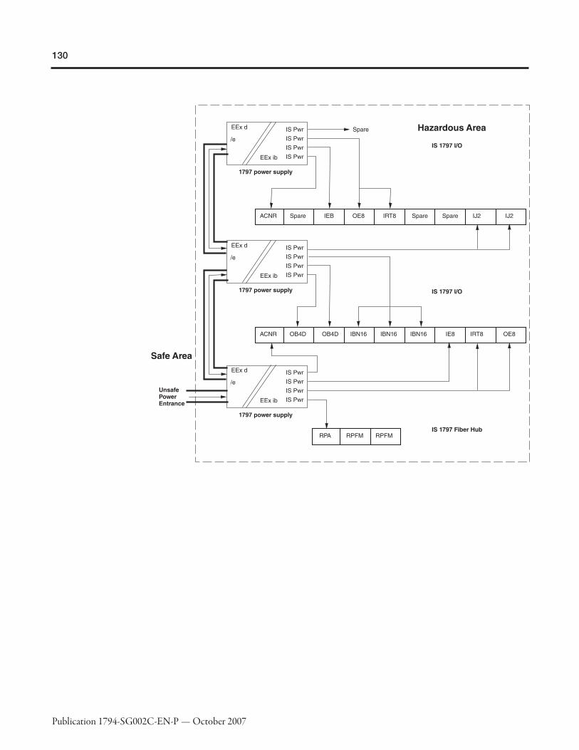
130
Publication 1794-SG002C-EN-P — October 2007

131
Publication 1794-SG002C-EN-P — October 2007
AAssssiiggnniinngg PPoowweerr SSuupppplliieess
Note the amount of power each module requires and assign it to a power supplyoutput. Continue to assign modules to the power supply output until the supply'soutput power rating is consumed.
Each power supply output in the FLEX Ex system is rated for 8.5W. Modules can beattached to the output until their combined power equals that number. Do not exceedthe power supply maximum of 8.5W.

132
Publication 1794-SG002C-EN-P — October 2007
HHaazzaarrddoouuss AArreeaa IInnssttaallllaattiioonn
The following illustration provides an example of how power supplies are arrangedwithin the FLEX Ex system when using fiber hubs.
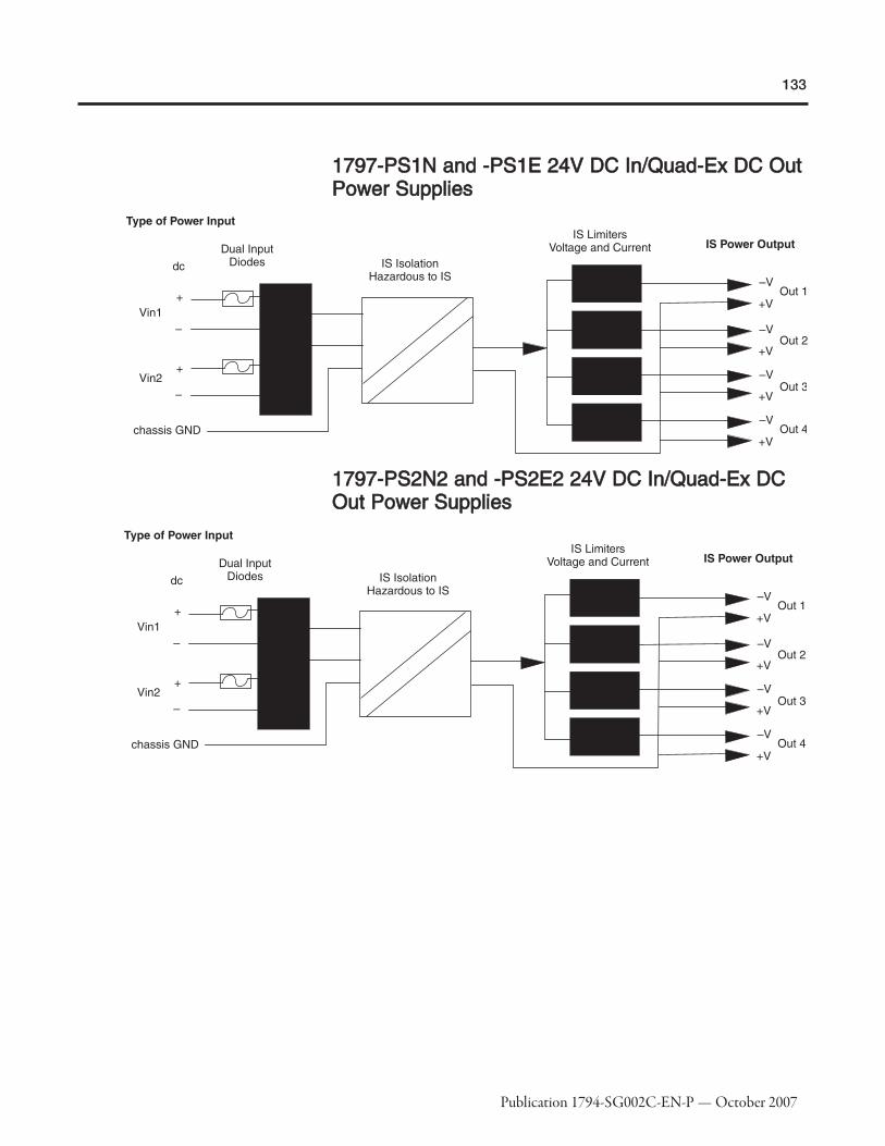
133
Publication 1794-SG002C-EN-P — October 2007
11779977--PPSS11NN aanndd --PPSS11EE 2244VV DDCC IInn//QQuuaadd--EExx DDCC OOuuttPPoowweerr SSuupppplliieess
11779977--PPSS22NN22 aanndd --PPSS22EE22 2244VV DDCC IInn//QQuuaadd--EExx DDCCOOuutt PPoowweerr SSuupppplliieess

134
Publication 1794-SG002C-EN-P — October 2007
1797-PS1N 1797-PS1E 1797-PS2N2 1797-PS2E2
Intrinsically Safe Module Type
Class I, Division 1, Groups A…D T4 (ULand C-UL)Class II, Division 1 Groups E…G (UL andC-UL)Class III (UL and C-UL)
EEx de [ib] IIC T4
Class I Division 1 Groups A…D T4 (UL,C-UL and FM)Class II Division 1 Groups E…G (UL, C-UL)Class III
Zone 1: II 2G EEx de [ib] IIC T4 (DMT02 ATEX E253 X)Zone 22: II 3D IP54 T90C
Intrinsically Safe Output TypeClass I, II, III, Division 1 & 2, GroupsA…G (UL and C-UL)
EEx ib IICClass I, II, III Division 1 & 2Groups A…G (UL, C-UL, and FM)
EEx ib IIC
Input Connector Terminals Terminals 1, 2, 4, 5 Terminals 1, 2, 4, 5 (earth symbol) Terminals 1, 2, 4, 5 Terminals 1, 2, 4, 5
Operating Voltage Range85…250V ac120…250V dc
85…253V ac 19…32V dc 18…32V dc
Current Consumption 0.35…0.9 A 0.9 A 3.1 A 1.3…1.6 A
Ripple — — 5% ac 5% ac
Input Power Entry1 in NPT, ≤ 6 in conduit allowed betweenpower supply and seal (UL and C-UL)
Increased safety
1 in NPT, 6 in conduit allowed betweenpower supply and seal (UL and C-UL)1 in NPT, 0 in conduit allowed betweenpower supply and seal (FM)
Increased safety
Output Connector Terminals Terminals 10…17 Terminals 10…17 Terminals 10…17 Terminals 10…17
Power Supply Output Power (W) 34 W✶ 34 W✶ 34 W✶ 34 W✶
Input Voltage, Max. 250V ac 253V ac 40V dc 40V dc
Voltage UO ≤ 9.5V ≤ 9.5V ≤ 9.5V ≤ 9.5V
Current IO ≤ 1 A ≤ 1 A ≤ 1 A ≤1 A
CO (IIC) ≤ 500 nF ≤ 500 nF ≤ 500 nF ≤ 500 nF
LO (IIC) ≤ 8 μH ≤ 8 μH ≤ 8 μH ≤ 8 μH
Output Cable Resistance, Max. ≤ 0.1 Ω (both directions) ≤ 0.1 Ω (both directions) ≤ 0.1 Ω (both directions) ≤ 0.1 Ω
Power Supply Input Power 55 W 55 W 55 W 55 W
Power Dissipation 21 W 21 W 21 W 21 W
Thermal Dissipation, Max. 71.67 BTU/hr 71.67 BTU/hr 71.67 BTU/hr 71.67 BTU/hr
Dimensions (HxWxD), Metric 174 x 174 x 128 mm 174 x 174 x 280 mm 174 x 174 x 128 mm 174 x 174 x 280 mm
Dimensions (HxWxD), Imperial 6.9 x 6.9 x 5.04 in 6.9 x 6.9 x 11.0 in 6.9 x 6.9 x 5.04 in 6.9 x 6.9 x 11.0 in
Weight, Metric 7.3 kg 7.7 kg 7.3 kg 7.7 kg
Protections Class IP 66/NEMA 7B IP 65/NEMA 7B IP 66/NEMA 7B IP 65/NEMA 7B
✶8.5 W at each of 4 outputs.

135
Publication 1794-SG002C-EN-P — October 2007
Step 5 - Select:
� optional FLEX Ex accessoriesSelecting FLEX ExAccessories11779944--CCEE11 aanndd --CCEE33 EExxtteennddeerr CCaabblleess
Use the optional 1794-CE1 (0.3m, 1ft) or 1794-CE3 (0.9m, 3ft) extender cable (oneper system) to arrange your system in two rows or split your system into horizontaland vertical orientation. The cable can be used between any module or adapter.

136
Publication 1794-SG002C-EN-P — October 2007
11779977--BBOOOOTT CCoonnttrroollNNeett BBNNCC BBoooott
Use the ControlNet BNC boot, trunk isolator, and marking kit in your cableconnections.
The 1797-BOOT covers the BNC connector on the ControlNet Ex trunk cable. The kitcontains 50 pieces.
11779977--IINNSS TTrruunnkk IInnssuullaattoorr aanndd 11779977--EEXXMMKK MMaarrkkiinnggKKiitt
The 1797-INS is a bag of 50 assorted insulators that you can use to replace thoseshipped with the product. The 1797-EXMK is a marking kit for FLEX Ex cable,containing 100 pieces.
CCoonnttrroollNNeett EExx TTaappss
1797-TPS ControlNet Ex Straight T-Tap

137
Publication 1794-SG002C-EN-P — October 2007
1797-TPR ControlNet Ex Right-Angle T-Tap
1797-TPYS ControlNet Ex Straight Y-Tap
1797-TPYR ControlNet Ex Right-Angle Y-Tap
1797-XT ControlNet Ex 75Ω Terminator
The terminator is sold in lots of 50.

138
Publication 1794-SG002C-EN-P — October 2007
1797-TCAP ControlNet Tap Terminator
This kit contains five pieces.
1786-RG6 Coax Trunk Cable
The 1786-RG6 Coas Trunk Cable can be used in Flex Ex applications in hazardousareas.

139
Publication 1794-SG002C-EN-P — October 2007
Step 6 - Select:
� panel mount or DIN Rail mount
� appropriate number of panels orDIN Rails based on the number ofmodules and the physicalrequirements
� one end cap per controller system
Mounting the FLEX ExSystemYou can horizontally or vertically mount the FLEX Ex system on a standard 35 mm DINRail. The adapter and terminal base easily snap on the DIN Rail by hand. Use a flat-blade screwdriver to remove components from the DIN Rail.
Screw holes allow you to horizontally or vertically panel-mount your system in anenclosure. An example of a FLEX Ex DIN-Rail mounted system is shown in 30239.

140
Publication 1794-SG002C-EN-P — October 2007
When properly installed, FLEX Ex is grounded through the DIN Rail to chassis ground.Use zinc-plated, yellow-chromated steel DIN Rail to assure proper grounding. Usingother DIN Rail materials (e.g. aluminum, plastic, etc.) which can corrode, oxidize, orare poor conductors can result in improper or intermittent platform grounding.
If installing FLEX Ex on non-recommended DIN Rail materials, use the mountingholes provided in each terminal base or a 1794-NM1 mounting kit with approvedmounting bracket. Use mounting screws with star washers to provide the FLEX Explatform with a chassis ground connection that is not likely to be affected by shock,vibration, or oxidation over time.
The hook (on the terminal base) and adjacent connection point (on thecommunication adapter) keep the terminal bases tight together. These componentsare capable of maintaining a reliable connection in case of shock and/or vibration.Refer to the environmental conditions information in each module's specifications.
The hook (on the terminal base) and adjacent connection point (on thecommunication adapter) keep the terminal bases tight together. These componentsare capable of maintaining a reliable connection in case of shock and/or vibration.Refer to the environmental conditions informations in each module's specifications.

141
Publication 1794-SG002C-EN-P — October 2007
Step 7 - Select:
� the ControlNet Ex networkSelecting SoftwareYour selection of modules and network configuration determines what softwarepackages you need to configure and program your system.
If you have a: Use this network: You need: Order this catalog number:
1797-ACNR15ControlNet Ex
RSNetWorx for ControlNetRSLinxRSLogix 5000
9357-CNETL39355-WAB100ENE9324-RL5300ENE
1797-BIC and -CEC
EtherNet/IP
RSNetWorx for EtherNet/IP
RSLinxRSLogix 5000
9357-ENETL3 individually9357-ANETL3 combined9355-WAB100ENE9324-RLD300ENE✶
DeviceNetRSNetWorx for DeviceNet RSLinxRSLogix 5000
9357-DNETL39355-WAB100ENE9324-RLD300ENE✶
Remote I/ORSLinxRSLogix 5000
9355-WAB100ENE9324-RLD300ENE✶
✶Order RSLogix 5000 bundled with RSNetWorx and RSLinx with catalog number 9324-RLD300NXENE.
RRSSLLooggiixx 55000000PPrrooggrraammmmiinnggSSooffttwwaarree
RSLogix 5000 Enterprise series software is designed to work with RockwellAutomation's Logix platforms and the Logix5000 family of controllers. RSLogix 5000Enterprise series software is an IEC 61131-3 compliant software package that offersrelay ladder, structured text, function block diagram, and sequential function charteditors for you to develop application programs. RSLogix 5000 Enterprise seriessoftware also includes axis configuration and programming support for motioncontrol.
RSLogix 5000 Software Requirements
Description Value
Personal ComputerPentium II 450 MHz minimum733 MHz recommended
Software RequirementsMicrosoft Windows NT version 4.0 with Service Pack 6A or greaterMicrosoft Windows 2000 with Service Pack 1 recommended
RAM128 Mbytes of RAM minimum256 Mbytes of RAM recommended
Hard Disk Space 100 Mbytes of free hard disk space (or more based on application requirements)
Video Requirements256-color VGA graphics adapter800 x 600 minimum resolution (1024 x 768 recommended)
NNeettwwoorrkkCCoonnffiigguurraattiioonnSSooffttwwaarree
RSNetWorx software for ControlNet (9357-CNETxx) is the configuration tool for yourControlNet Ex networks. RSNetWorx software lets you create a graphicalrepresentation of your network configuration and configure the parameters that defineyour network.
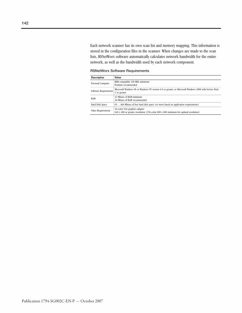
142
Publication 1794-SG002C-EN-P — October 2007
Each network scanner has its own scan list and memory mapping. This information isstored in the configuration files in the scanner. When changes are made to the scanlists, RSNetWorx software automatically calculates network bandwidth for the entirenetwork, as well as the bandwidth used by each network component.
RSNetWorx Software Requirements
Description Value
Personal ComputerIBM compatible 120 MHz minimumPentium recommended
Software RequirementsMicrosoft Windows 98 or Windows NT version 6.0 or greater, or Microsoft Windows 2000 with Service Pack1 or greater
RAM32 Mbytes of RAM minimum48 Mbytes of RAM recommended
Hard Disk Space 65 ... 460 Mbytes of free hard disk space (or more based on application requirements)
Video Requirements16-color VGA graphics adapter640 x 480 or greater resolution (256-color 800 x 600 minimum for optimal resolution)

143
Publication 1794-SG002C-EN-P — October 2007
SummaryAs you select devices for your FLEX Ex system, keep in mind:
�� Step Remember to Select1 Select a communication adapter and fiberhub
Choose the adapter and optional fiber hub to extend the lengthof the ControlNet Ex segments.
� the appropriate communication network and related adapter
2 Select devices for an intermixed system
Choose the proper devices to create an intermixed system usingthe same communication adapter.
� the appropriate devices to create a system with 1794 and1797 I/O modules
3 Select I/O devices based on field devices
� location of the device� number of points needed� appropriate catalog number� number of points available per module� number of modules
� I/O modules
4 Select a terminal base
Choose an appropriate terminal base for your modules.� the appropriate terminal base unit(s) for your modules
5 Select power supplies and ensuresufficient power for the communication adapter andmodules
If power consumption exceeds the maximum for a single powersupply, install additional power supplies.
� additional power supplies as necessary
6 Select optional accessories
Choose appropriate accessories to enhance your system.� optional accessories as necessary
7 Determine mounting requirements
Determine whether to panel mount or DIN Rail mount the FLEXEx system.
� panel mount or DIN Rail mount� appropriate number of panels or DIN Rail based on the
number of modules and the physical locations of thosemodules
8 Select software
Based on the system design, determine the software productsyou need to configure and program your application.
� software necessary to configure and program your I/Omodules

144
Publication 1794-SG002C-EN-P — October 2007
RReellaatteedd DDooccuummeennaattiioonn
Additional user documentation presents information according to the tasks youperform and the programming environment you use. Refer to the table below forinformation on 1794 FLEX I/O publications.
FLEX Ex Related Publications✶
Cat. No. Description Pub.No.FLEX Ex System 1797 Series FLEX Ex System Certification Reference Manual 1797-6.5.6
Communication
1797-ACNR15 Dual Media ControlNet Ex 1.5 Adapter 1797-5.14
1797-RPA ControlNet Ex Coax Drop Repeater Module1797-5.15
1797-RPFM ControlNet Ex 3 km Fiber Media Port Adapter
Intermixed
1797-BIC Bus Isolator Module1797-5.13
1797-CEC Flexbus Connector Module
1797-BCNR Redundant ControlNet Barrier Module 1797-5.35
Bases1797-TB3 3-Tier Screw Clamp Terminal Base Unit
1797-5.11797-TB3S 3-Tier Spring-Clamp Terminal Base Unit
Digital1797-IBN16 16 pt Non-Isolated NAMUR Input Module 1797-5.7
1797-OB4D 24V dc 4 pt Non-Isolated Source Output Module 1797-5.6
Analog
1797-IE8 8 pt 16 bit Single-Ended Non-Isolated Analog Input Module
1797-5.51797-6.5.1
1797-IE8H8 pt 16 bit Single-Ended Non-Isolated Analog Input Modulewith HART capability
1797-IE8NF8 pt 16 bit Single-Ended Non-Isolated Analog Input Modulewith Noise Filter
1797-IRT88 pt 16 bit Non-Isolated RTD Thermocouple/mV InputModule
1797-5.4
1797-OE8 8 pt 13 bit Single-Ended Non-Isolated Analog Output Module1797-5.31797-6.5.11797-OE8H
8 pt 16 bit Single-Ended Non-Isolated Analog Input Modulewith HART capability
Counter 1797-IJ2 2 Input Frequency Module 1797-5.9
Power Supplies
1797-PS1N FLEX Ex 85-250V AC In/Quad-Ex DC Out Power Supply 1797-5.34
1797-PS1E FLEX Ex 85-253V AC In/Quad-Ex DC Out Power Supply 1797-5.33
1797-PS2N2 FLEX Ex Power Supply in explosion proof enclosure 1797-5.12
1797-PS2E2 FLEX Ex Power Supply in explosion proof enclosure 1797-5.8
Accessories
1797-CE1S FLEX Ex Bus Isolator Extender Cable, 0.3 m (1 ft)1797-5.20
1797-CE3S FLEX Ex Bus Isolator Extender Cable, 0.9 m (3 ft)
1797-EXMK FLEX Ex Cable Marking Kit 1797-5.23
1797-TCAP ControlNet Tap Terminator 1797-5.30
✶Contact your local A-B distributor for information on ordering any of the above publications.For electronic copies of these publications, go to http://www.ab.com/literature