Embed Size (px)
Citation preview

A0A091 264 ACKENHEIL AND ASSOCIATES INC BALTIMORE MD F/G 13/13
NATIONAL DAN INSPECTION PROGRAM. UNIVERSITY OF MARYLAND BALTIMO--ETC(U)AUG 80 J 0 HAINLEY, T E DEBES DACW31-80-C-0026UNCLASSIFIED NL
1m1mmh1hhhhhhmmlE -E-/mhE///IllEiliIIIhIl'mIIIIIII

ci) IMOALkOD T
mVPAS OF INSPCTIOJNP
PREARD PORT
B ALTMOE DISRICTIORON GIER
0 BALTIMOPREP ARYLD F2

I P REFACE
This report is prepared under guidance contained in the RecommendedGuidelines for Safety Inspection of Dams, for Phase 1 investigations.Copies of these guidelines may be obtained from the Department of theArmy, Office of Chief of Engineers, Washington, D.C. 20314.
The purpose of a Phase I investigation is to identify expeditiouslythose dams which may pose hazards to human life or property. Theassessment of the general condition of the dam is based upon visualobservations and review of available data. Detailed investigation andanalyses involving topographic mapping, subsurface investigations,material testing, and detailed computational evaluations are beyondthe scope of a Phase 1 investigation; however, the inspection is intendedto identify any need for such studies which should be performed by theowner.
In reviewing this report, it should be realized that the reportedcondition of the dam is based on observations of field conditions atthe time of inspection along with data available to the inspectionteam. In cases where the reservoir was lowered or drained prior toinspection, such action, while improving the stability of the dam,removes the normal load on the structure and may obscure certain condi-tions which might otherwise be detectable if inspected under the normaloperating environment of the structure.
It is important to note-that the condition of the dam depends onnumerous and constantly changing internal and external factors whichare evolutionary in nature. It would be incorrect to assume that thepresent condition of the'dam will continue to represent the conditionof the dam at some point in the future. Only through frequent inspec-tions can unsafe conditions be detected and only through continued careand maintenance can these conditions be prevented or corrected.
Phase 1 inspections are not intended to provide detailed hydrologicand hydraulic analyses. In accordance with the established Guidelines,the spillway design flood- is based on the estimated "Probable MaximumFlood" (PMF) for the region (greatest reasonably possible storm runoff),or fractions thereof. The spillway design flood provides a measure ofrelative spillway capacity and serves as an aid in determining the needfor more detailed hydrologic and hydraulic studies, considering thesize of the dam, its general condition, and the downstream damagepotential.
t
7 @

PHASE 1 INSPECTION REPORTNATIONAL DAM INSPECTION PROGRAM
SYNOPSIS OF ASSESSMENT AND RECOMMENDATIONS
NAME OF DAM: University of MarylandBaltimore County Dam
STATE LOCATED: MarylandCOUNTY LOCATED: BaltimoreSTREAM: West Branch of Herbert Run,
a tributary of the Patapsco RiverDATES OF INSPECTIONS: May 15, 1980 and July 31, 1980 -
COORDINATES: Lat. 76%. 42.2'; Long. 39* 15.7'
ASSESSMENT
LI4BC Dam is classified as a "small" size, "high" hazard dam in accordancewith U. S. Army Corps of Engineers damn safety critera.
Based on the evaluation of available design information and visual observa-tions of conditions as they existed on the dates of the field reconnaissances,the general condition of tJMBC Dam is considered to be good. However, theaccumulated debris and sediment obstructing the principal spillway entrancestructure is considered to represent a potential hazard to the dam.Immediate removal of the debris and sediment and construction of an improvedtrash rack(s) or cage is advised. The presence of surface erosion on theembankment-spillway abutment and around the impact stilling basin, and treeand woody shrub growth located along the enibankment-spillway abutment,downstream slope and exit channel, are considered minor deficiencies inneed of maintenance.
Guideline criteria recommends spillway design floods from 0.5 PMF to thePMF for "small" size, "high" hazard dams. Based on the observed downstreamhazard, a PMF spillway design flood is considered appropriate for UMBC Dam.Review of available hydrologic/hydraulic design calculations indicate theemergency spillway can pass the PMF without overtopping the dam embankment.Therefore, spillway capacity is assessedadequate in accordance withrecommended guideline criteria.
RECOMMENDATIONS
The following recommendations should be implemented as soon as possible:
1. Develop and institute a flood surveillance, warning, and evacuationplan.
2. Remove accumulated debris and sediment from impoundment basin andtrash rack, and downstream exit channel.
3. Replace the existing damaged trash rack with a larger and more durableone.

4. Remove tree and woody shrub growth from upstream embankment-spillway
abutment.
5. Install anchor bolts and secure principal spillway access ladder
co riser wall.
6. Periodically observe areas where wet zones were encountered, Note any
change in condition and ascertain cause of intermittent ponded water.
7. Repair protective screen fence at impact stilling basin.
""'a Maryland Registrati o. 5284Vice President
At,
Timothy E.(Uft4, .E. Date
Maryland Regist ation No. 12020Project Engineer
APPROVED B:W.PECK ate
olonel, Corps of Engineers
istrict Engineer
7Accession_ For.
7SGRA&Io
TAB
] .-_ i . .. ... .. . . - - --t MI. 'nc,
St- .
iiii

UNIVERSITY OF MARYLANDBALTIMORE COUNTY
DAM
j Overview of Dam
iv

TABLE OF CONTENTS
Page
PREFACE .. .. .... ...... ...... ..... .... i
SYNOPSIS OF ASSESSMENT AND RECOMMENDATIONS. .. ..... ... ii
OVERVIEW PHOTOGRAPH .. .. ..... ..... ...... ... iv
SECTION 1 - PROJECT INFORMATION -
1.1 General .. ..................... 11.2 Description of Project .. ... *.. .*..............11.3 Pertinent Data .. .. ..... ..... ...... ... 2
SECTION 2 - ENGINEERING DATA
2.1 Design. .. ... ...... ..... ...... .... 42.2 Construction .. .. ..... ..... ...... .... 52.3 Operation. .. ..... ...... ...... ...... 52.4 Evaluation .. .. ..... ..... ...... ...... 5
SECTION 3 - VISUAL INSPECTION
3.1 Findings. .. ... ...... ..... ...... ... 73.2 Evaluation .. .. ..... ..... ...... ...... 8
SECTION 4 - OPERATIONAL FEATURES
4.1 Procedure .. ... ...... ...... ..... ... 94.2 Maintenance of Dam ... ... ...... ..... .... 94.3 Inspection of Dam .. ................. 94.4 Maintenance of Operating Faciiiies............94.5 Warning System .. .. ..... ..... ...... ... 94.6 Evaluation .. .. ..... ...... ..... ...... 9
SECTION 5 - HYDROLOGY AND HYDRAULICS
5.1 Evaluation of Features. .. ... ...... ........ 10
SECTION 6 - STRUCTURAL STABILITY
6.1 Evaluation of Structural Stability. .. ... ........ 12
v

TABLE OF CONTENTS (cont'd)
Page
SECTION 7 - ASSESSMENT AND RECOMMENDATIONS
7.1 Dam Assessment ..... ..................... .... 147.2 Recommendations ...... .................... ... 15
APPENDIX A - VISUAL OBSERVATIONS CHECK LIST AND FIELD SKETCHVisual Observations Check List .... ......... AlField Sketch ................... AOField Profile and Section ........... All
APPENDIX B - ENGINEERING DATA CHECK LIST ... .......... B1APPENDIX C - PHOTOGRAPHS
Photograph Key Map ...... ............... ClPhotographs 1 through 8 ...... ............ C2
APPENDIX D - HYDROLOGIC AND HYDRAULIC ENGINEERING DATAHydrologic and Hydraulic Engineering Data . . D1Hydrology Review .... ................ ... D2PMF and 100 yr. Design Calculations and
Flood Hydrograph ... ............... .... D3APPENDIX E - LOCATION PLAN AND PLATES
Location Plan ....... ................. ElPlates 1 through 6 ... ............... .... E2
APPENDIX F - REGIONAL GEOLOGYRegional Geology ...... ................ FlGeologic Map ....... .................. F2
vi

PHASE 1 REPORTNATIONAL DAM INSPECTION PROGRAM
UNIVERSITY OF MARYLANDBALTIMORE COUNTY
DAMNDI ID. NO. MD 34
SECTION 1
PROJECT INFORMATION
1.1 GENERAL
A. AUTHORITY: This study was performed pursuant to the authoritygranted by the National Dam Inspection Act, Public Law 92-367,to the Secretary of the Army, through the Corps of Engineers, toconduct inspections of dams throughout the United States.
B. PURPOSE: The purpose of this study is to determine if the damEonstitutes a hazard to human life or property.
1.2 DESCRIPTION OF PROJECT
A. DAM AND APPURTENANCES
1. Embankment: 'ihe UMBC Dam was constructed as a zonedearthfill structure. The dam is approximately 255 ft.long, with a maximum toe to crest height of 41 ft. and acrest width of 20 ft. The upstream embankment slope has aninclination of 3H:1V. The downstream embankment slope hasinclinations of approximately 20H:1V from the embankmenttoe to 26 ft. below the dam crest and 3H:lV from this pointto the dam crest. Riprap protection is provided on thedownstream embankment-spillway abutment.
2. Seepage Control Provisions: According to design drawings,seepage control is provided by a cutoff trench and a filterdrain. The cutoff trench is located at the dam centerlineand is-continuous with-the embankment-core.- Seepage iscollected by a filter drain located along the side walls ofthe impact stilling basin. The collected seepage isdischarged into the downstream channel by outlet pipesexiting through the impact stilling basin side walls.
3. Flood Discharge Facilities: Flood discharge facilitiesconsist of a principal spillway outlet pipe and an emergencyspillway channel.
The principal spillway consists of a reinforced concreteentrance structure, a 259 ft. long 72 in. dia. reinforcedconcrete outlet pipe and a reinforced concrete impactstilling basin.
The emergency spillway channel is excavated into naturalearth and is located at the left abutment. The spillwaychannel is approximately 150 ft. wide with a 30 ft. longlevel control section at the dam centerline.
1

B. LOCATION: The UMBC Dam is situated across the west branch ofHe-rbe-rt Run. The darn is located on the UMBC campus approximately0.5 miles northwest of Arbutus, Maryland in Baltimore County.
C. SIZE CLASSIFICATION: The dan has a maximum temporary storagecapacity of 185 ac. -ft. and a toe to crest height of 41 ft.Based on this criteria, the dam is classified as a "small" sizestructure.
D. HAZARD CLASSIFICATION: The UMBC Dam is classified as a "high"hazard structure. In the event of a dam failure, more than 25inhabited structures are expected to be subject to substantialdamage and loss of life along an approximate 3.5 mile channelreach of Herbert Run from the damn to the Patapsco River.
E. OWNERSHIP: UMBC Dam is owned by the University of Maryland, -
Coll~ege Park, Maryland 20742. All correspondence concerningthe maintenance and operation of the dam should be directed toLeon Herring, Director, Physical Plant Department, University ofMaryland, Baltimore County, 5401 Wilkins Avenue, Catonsville,Maryland 21228. Inquiries concerning the safety operation ofthe dam should be directed to Robert Schirmer, Safety Engineer,Department of Public Safety.
F. PURPOSE OF DAM: UMBC Darn was constructed for use as a floodcontrol structure.
G. DESIGN AND CONSTRUCTION HISTORY: The dam was designed by Rummel,Klepper & Kahl, Consulting Engineers, Baltimore, Maryland withthe assistance of the Soil Conservation Service. The dam wasconstructed by Harry T. Campbell & Sons Co. under the supervi-sion of the State of Maryland, Department of General Servicesand the design engineer. Construction of the dam took placebetween June 1975 and September 1976.
FH. NORMAL OPERATING PROCEDURES: Under normal operating conditions,normal stream base flow is discharged through the principalspillway pipe.
1.3 PERTINENT DATA
A. DRAINAGE AREA 1.2 sq. mi.
B. DISCHARGE AT DAM FACILITY
Maximum known flood at dam facility UnknownMaximum spillway capacity at El. 175.0,3 ft. below top of dam 11,700 cfs
C. ELEVATION (FEET ABOVE MSL)
Const-.ucted top of dam El. 178.0Design high water El. 175.0Normal pool None
2

C. ELEVATION (FEET ABOVE MSL. CONT.)
Emerqency spillway crest El. 166.5Maximum tailwater UnknownUpstream invert of principal spillway pipe El. 139.5Downstream invert of principal spillway pipe El. 136.9Streambed at dam centerline El. 140+Downstream toe of dam El. 1371
D. RESERVOIR LENGTH
Length of maximum pool 1,733 ft.Length of normal pool N/A
E. STORAGE CAPACITY
Constructed top of dam 185 ac.-ft.Emergency spillway crest level 90 ac.-ft.
F. RESERVOIR SURFACE
Constructed top of dam 12 acresEmergency spillway crest level 10 acres
G. DAM EMBANKMENT
Type EarthfillLength 255 ft.Height 41 ft.Top width 20 ft.Side slopes
Downstream . 3H:1V from dam crest to26 ft. below crest,
20H:1V from 26 ft. belowdam crest to embankment toe
Upstream 3H:1VZoning YesImpervious core YesCutoff provisions Cutoff trenchGrout curtain No
H. EMERGENCY SPILLWAY CHANNEL
Type Trapezoidal earth channelWidth 150 ft.Crest elevation 166.5 ft.Gate NoneUpstream channel Vegetated earth with a
negative 2 percent slopeControl crest length 30 ft.Downstream channel Vegetated earth with a
positive 2 percent slopeLength of channels 694 ft., curved
3

SECTION 2ENGINEERING DATA
2.1 DESIGN
A. DATA AVAILABLE: The following available data may be obtainedfrom the Dam Safety Division, Maryland Water Resources Admini-stration.
1. Hydrology and Hydraulics: Available information includes ai statistical data sheet, Peak Discharge versus Storm Recurrence
Interval Plot, 25 yr. and 50 yr. flood plain delineationmaps, Drainage Study, West Branch of Herbert Run preparedby Van-Reuth & Weidner, Inc., 6 hr. 100 yr. and PMPhydrological calculations and flood hydrographs, stage-storage and stage-area curves, reservoir routing calcula-tions, and a dam breach analysis.
2. Embankment: Design information includes constructiondrawings, an environmental impact statement on proposedconstruction, geological investigation summary, laboratorytest data, stability analysis, and drilling and test pitlogs. Information included in Geotechnical Investigationand Design Recommendations for a Proposed Impoundment atThe University of Maryland, Baltimore County Campus, datedJune 1974. Report is available from Rummel, Klepper &Kahl.
3. Appurtenant Structures: Design information is limited toconstruction drawings and principal spillway pipe designcalculations.
B. DESIGN FEATURES: Dam and appurtenances were designed in accord-ance with Soil Conservation Service structure classification "C"criteria ("high" hazard).
1. Embankment: The zoned earthfill dam structure consists ofa semi-impervious core, and upstream and downstream embank-ment shells. The embankment core extends from the cutofftrench to 12 ft. below the dam crest. Core side slopestaper on a 2H:1.5V inclination from a 34 ft. wide base to atop width of 10 ft. Select borrow, obtained from excavationof the impoundment basin and left side slope, was used toconstruct the embankment shells and core.
A two (2) ft. thick blanket of riprap was placed around theprincipal spillway entrance structure and impact stillingbasin on the upstream and downstream embankment slopesrespectively.
2. Seepage Control Provisions: According to design drawings,the earthfill cutoff trenci was constructed as a continua-tion of the embankment core. The cutoff trench has a base
4
4 ). 2

width of 20 ft., increasing to a top width of 60 ft., withlH:l.5V side slopes. Select borrow, obtained from sourcesidentified above, was used to backfill the trench excavation.
A filter drain was installed around the side walls of theimpact stilling basin. The drain consists of a 6 in. dia.perforated pipe imbedded in coarse filter material, protectedby a 1 foot thick blanket of fine filter material. Drainoutlets are located at the end of each impact stillingbasin wing wall.
Three (3) anti-seep collars were installed around theprincipal spillway outlet pipe. Anti-seep collars werelocated at impoundment base line Stations 19+55, 19+75 and19+95.
3. Flood Discharge Facilities: The 72 in. dia. principalspillway outlet pipe is supported by a continuous concrete -
cradle. The outlet pipe end section is supported andconnected to the reinforced concrete inlet wall of theimpact stilling basin. Outlet pipe flow is discharged intothe basin baffle block, through the basin outlets and intothe exit stream channel.
The emergency spillway is trapezoidal in shape with rightand left side slope inclinations of 3H:1V and 2.5H:1V,respectively. The overall length of the curved spillwaycrest and channels is 694 ft. The upstream spillwaychannel is approximately 370 ft. long with a negative2.0 percent slope. The downstream spillway channel isapproximately 304 ft. long with a positive 2.0 percentslope. The right side slopes of the spillway channel andthe exit stream channel are lined with a (two) 2 ft. thickblanket of riprap. Spillway flows are discharged directlyinto the downstream channel approximately 250 ft. downstreamof the dam centerline.
2.2 CONSTRUCTION: Based on review of available design drawings andfield observations, it may be concluded that the dam and appurtenanceswere constructed in general accordance with the intended designdrawings.
2.3 OPERATION: The UMBC dam is an uncontrolled, storm water managementfacility. The University of Maryland, Baltimore County Campus isresponsible for maintaining the principal spillway pipe and emergencyspillway channel.
2.4 EVALUATION
A. AVAILABILITY: Available design drawings and information wereobtained fr-om the Dam Safety Division, Maryland Water ResourcesAdministration and Rummel, Klepper & Kahl.
B. ADEQUACY: The design data provided is reasonably documented andcs onsidered adequate to evaluate the dam and appurtenant
structures in accordance with the scope of a Phase 1 study.
5

Based on the review of this data, the dam and appurtenantstructures are considered to have been designed in generalconformance with accepted engineering practice.
C. VALIDITY: Based on the available data, there is no reason toquestion the validity of the obtained design information ordrawings.
6

SECTION 3VISUAL INSPECTION
3.1 FINDINGS
A. GENERAL: The on-site reconnaissance of UMBC Dam consisted of:
1. Visual observations of the earth emban kment, abutments, andspillway channel.
2. Visual observations of exposed sections of the principalspillway pipe, impact stilling basin, impoundment basinand slopes, and downstream channel.
3. Visual search for hazardous conditions and safety defi-ciencies.
4. Evaluation of the downstream hazard potential.
5. Transit stadia survey of relative elevations along theembankment crest centerline, spillway, and across theembankment slopes.
Visual surveys were performed during periods when there wasno water impounded behind the dam structure.
A visual observation check list and field sketch are given inAppendix A. Specific observations are illustrated in photographsof Appendix C.
B. EMBANKMENT: Embankment slopes had fi'eld measured inclinationsapproximating 3H:1V and a crest width of 20 ft. Embankmentcrest and slopes had a dense grass covering and appearedstable. Trees and woody shrubs were located along the embankment-spillway abutment, extending from dam centerline to the impactstilling basin. Eroded tire ruts were observed along the damcrest, bottom of the spillway channel, and embankment-spillwayabutment (see field sketch).
C. APPURTENANT STRUCTURES
1. Pricial Spillway: The principal spillway entrancestructure trash rack was severely obstructed by wood,debris, and sediment. Trash rack cross members were badlydamaged and twisted.
Exposed concrete surfaces were observed free of spallingand cracking, and appeared in good condition.
2. Impact Stilling Basin: The concrete stilling basin appearedto be in good structural condition. Shallow soil erosionwas evident along the upstream sidewall. Stilling basinand baffle block discharge section were observed free ofdebris and flow obstructions.
7

The 6 in. dia. perforated pipe outlets could not be locatedunderneath the riprap protection. However, no drainage wasdiscernible near the stilling basin wing walls where thepipe outlets are supposedly located. Tree growth andsediment has accumulated in the exit channel directlydownstream of the stilling basin.
3. Emergency Spillway: Spillway channel bottoms and sideslopes are vegetated with a dense grass and appear stable.The right downstream channel side slope has riprap extendingfrom the channel bottom to about 6 ft. below the dam crest.Left and right spillway side slopes have field measuredinclinations of 2.5H:1V and 3H:1V respectively.
D. IMPOUNDMENT BASIN: Impoundment basin side slopes have moderateto steep inclinations and are well covered with vegetation andtrees. Appreciable quantities of debris and sediment haveaccumulated in the impoundment basin and approach channel withinapproximately 200 ft. upstream of the entrance structure.
E. DOWNSTREAM CHANNEL: The immediate downstream channel reach isabout 10 ft. wid~e and has stable side slopes. Channel sideslopes and banks are lined with grass, trees and thick brush
[ cover. No conditions were observed in the downstream channelthat might cause significant flow obstruction and present hazardto the dam.
Downstream from the dam, the west branch of Herbert Run flowsapproximately 3 miles south to its confluence with the PatapscoRiver. The commiunities of Arbutus and Cowdensville are respec-tively located approximately 0.5 and 1 mile downstream of thedam. In the event of a dam failure, more than 25 inhabitedstructures are expected to be subject to substantial damag andloss of life.
3.2 EVALUATION
A. EMBANKMENT: In general, the dam embankment is adequatelymaintained and appears in good condition. The eroded tire ruts,observed on the embankment-spillway abutment, are consideredsurficial deficiencies in need of maintenance. Trees and woodyshrubs located along the embankment-spillway abutment willrequire removal.
B. APPURTENANT STRUCTURES: Accumulated debris and sediment,obstructing the entrance structure and encroaching upon thedownstream channel, should be removed and disposed of properly.The entrance structure trash rack should be removed and a largerand more durable trash rack provided.
In general, the spillway channel, principal spillway pipeand impact stilling basin appear to be in good condition.
8
*.J

SECTION 4OPERATIONAL FEATURES
4.1 PROCEDURE: The dam was designed as an uncontrolled structure andimpounds water only during flood conditions. The emergency spillwayis ungated and does not require a dam tender.
4.2 MAINTENANCE OF DAM: The dam embankment and appurtenant structuresare maintained by-the UMBC Physical Plant Department. Normal main-tenance includes periodically mowing the embankment slope and emergencyspillway channel and clearing the impoundment basin and trash rack ofdebris and sediment.
4.3 INSPECTION OF DAM: The dam is inspected by the UMBC Physical PlantDepartment periodically and after significant storms. UMBC campus -
police monitor the dam during periods of unusually heavy rainfall.Inspections generally consist of visually examining the embankmentand appurtenant structures and providing repair recommendations.
4.4 MAINTENANCE OF OPERATING FACILITIES: There are no operationalfacilities at the dam.
4.5 WARNING SYSTEM: The UMBC, Department of Public Safety, directed bythe Safe-ty Engineer would alert Baltimore County Police, MarylandState Police, and Civil Defense authorities in the event the emergencyspillway was activated. However, there is no formal flood warningplan presently in effect.
4.6 EVALUATION: Except for the condition of the approach channel andentrance structure trash rack, and the lack of a formal warningsystem, the maintenance and operational procedures in effect at thedam are considered adequate. However, a formal flood surveillance,warning and evacuation plan is needed for the protection of down-streami inhabitants. Also, a more thorough maintenance program isneeded to regularly remove collected debris and sediment from theprincipal spillway entrance structure.
9

SECTION 5
HYDROLOGY/HYDRAUL ICS
5.1 EVALUATION OF FEATURES
A. DESIGN DATA:. UMBC Dam has a watershed drainage area of750 acres vegetated primarily by grassland (65%) and woodland(15%) with some urban development (20%). Topographic reliefranges from El. 136 to El. 480. Hydrologic analyses were basedon Soil Conservation Service structure classification "C"criteria ("high" hazard).
The principal spillway pipe was sized to pass the runoff re-sulting from a 100 yr., 6 hr. storm without activating the -
emergency spillway. Estimated maximum pipe outflow is 700 cfs.Expected pool elevation for the 100 yr. storm is 166.5 ft., thelevel of the emergency spillway control crest.
The hydraulic capacity of the emergency spillway channel isreported to be 11,700 cfs when impounded storm water is atEl. 175.0, three (3) ft. below dam crest. Spillway capacity wasdesigned to pass a flood corresponding to 24.2 in. of runoff in6 hours without overtopping the dan embankment.
According to guideline criteria, "small" size, "high" hazarddamns have recommended spillway design floods ranging from0.5 PMF to the PMF. Based on the downstream hazard potential aPMF spillway design flood is considered appropriate for the damfacility. Routing calculations reviewed by this study indicatedam storage~and emergency spillway discharge capacity areadequate to pass 100 percent of the PMF.
The reviewed hydrologic/hydraulic design information is inaccordance with accepted engineering practice and is consideredto be adequate for the scope of a Phase 1 study.
B. EXPERIENCED DATA: Records are not kept of water impoundmentelevations or rainfall amounts. There is no record or report ofthe emergency spillway ever being activated.
C. VISUAL OBSERVATIONS: The principal spillway entrance structurewas severely obstructed by debris and sediment. Such an obstruc-tion is undesirable and may pose a potential hazard to the dam.
*1 Accumulated sediment was also found deposited directly downstreamof the impact stilling basin. Although these sediment deposits arenot considered to represent a significant hazard at this time,immediate removal of the sediment and debris at both the entrancestructure and stilling basin is recommended. Tree and woodyshrub growth along the embankment-spillway abutment may affectspillway hydraulic performance and should be removed.
10

D. OVERTOPPING POTENTIAL: Hydromneteorological Report No. 33indicates the adjuste 6 hr. PMF direct rainfall for the subjectsite area is 21.7 in. Routing calculations indicate dami storageand emergency spillway discharge capacity is adequate to pass aflood corresponding to 24.2 in. of runoff in 6 hrs. withoutIovertopping the dam crest. Based on this data, it is consideredunlikely the dam embankment will be overtopped.
E. EMERGENCY SPILLWAY ADEQUACY: The data previously developedindicates that impoundment storage and spillway hydrauliccapacity is adequate to pass 100 percent of the PMF. The damand spillway are therefore considered adequate and in accordancewith recommended criteria.
F. DOWNSTREAM CONDITIONS: Downstream of the dam, Herbert Runempties into the Patapsco River directly south of Relay, Maryland.In this approximate 3 mile channel reach and estimated floodplain, more than 25 inhabited structures are expected to besubject to substantial damage and loss of life in the event of adam failure.
Herbert Run has a natural channel gradient of about 1.0 percent,and underpasses ten state and county bridges before merging withthe Patapsco River.

SECTION 6STRUCTURAL STABILITY
6.1 EVALUATION OF STRUCTURAL STABILITY
A. VISUAL OBSERVATIONS
1. Embankment: Embankment deficiencies identified in Section3.1-B are not considered to have a significant affect ondam stability. In general, the structural condition of theembankment slopes is assessed as good at the presenttime.
2. Appurtenant Structures: Visual observation of tile spillwaychannel did not reveal evidence of structural distress thatwould significantly affect dam stability. However, thedebris and sediment obstructing the entrance structureshould be immnediately removed to reduce the risk of cloggingduring a flood.
B. DESIGN AND CONSTRUCTION DATA
1. Subsurface Exploration: Design drawings indicate 16 augerbo-rings and 25 standard test borings were drilled in thevicinity of the proposed dam site and upstream and downstreamchannels. In addition, 13 test pits were excavated in thesame general area. Test boring and test pit logs indicatethe predominant presence of silt, clay, and sand soilmixtures between 0 and 8 ft. below ground surface. Below 4to 8 ft., a cobble and gravel layer, mixed with silt andclay was encountered.
2. Slope Stability Analysis: Slope stability of upstream anddownstream embankment -slopes was evaluated using a computercircular arc method. The analysis considered a 40 ft. highzoned earthfill embankment with 3H:1V side slopes. Analyseswere based on the dam cross section at the location of theprinciple spillway pipeline. Critical factor of safetyvalues against shear failure of 3.18 and 1.44 were obtainedfor steady state seepage conditions of the downstream slopeand normal pool conditions for the upstream slope, respec-tively.
.13. Seepage Analysis: No calculations or references were found.
4. Laboratory Testing: Classification, compacted dry densityan sWe-ar strengt tests were performed on selected samplesof foundation and proposed borrow soils. Soil samples wereobtained by split spoon samplers and from test pit excavations.
Results of classification tests indicate GM, SC, SM, CH,and CL-ML soils are predominant at the dam site. Consolidatedquick direct shear tests were performed to estimate the
12

shear strength of compacted borrow soils. Test resultsindicate shear strength values of =11%, c = 2,400 psf,and 6 = 25% c = 1,200 psf for clay and general excavationsoils.
5. Appurtenant Structures: The available principal spillwayentrance structure, pipe, and impact stilling basin designdrawings and calculations, were reviewed for structuraladequacy. Based upon this review and reported performancehistory, these structures are considered structurallyadequate with the exception of the entrance structure trashrack.
C. OPERATING RECORDS: Operating records are not maintained.
D. POST-CONSTRUCTION CHANGES: There have been no reports orevidence of post-construction changes at this dam facility.
E. SEISMIC STABILITY: Based on visual observations, review ofstatic slope stability analyses, and the past performancehistory of the dam, the static stability of the embankmentslopes is considered to be adequate.
According to guideline criteria, the dam is located in a SeismicZone 1 area (low seismic probability). Based upon this lowseismic probability, the static stability of the dam, and therecommended criteria for evaluating the seismic stability ofdams, the seismic stability of the dam is presumed to be adequate.
13

SECTION 7ASSESSMENT AND RECOMMENDATIONS
7.1 DAM ASSESSMENT
A. EVALUATION
1. Embankment: The observed deficiencies presented in Section3.1-A aesurficial in scope and are not considered torepresent a hazard to the darn at this time. However, necessaryrepairs or corrections should be made. In general, visualobservations indicate the dam embankment crest and slopesare adequately maintained and in good condition.
2. Appurtenant Structures: Accumulated debris and sediment,obstructing the entrance structure and encroaching upon thedownstream channel, should be removed and disposed ofproperly. The entrance structure trash rack should beremoved and a larger and more durable one provided.
In general, the principal spillway entrance structure andimpact stilling basin are assessed in fair and good condi-tion respectively.
3. Overtopping Potential: U.S. Army Corps of Engineers damsfty criteria recommends a spillway design flood ranging
from 0.5 PMF to the PMF. Based on the observed downstreamhazard, a PMF design flood is considered appropriatefor U.RBC Darn. Hydrologic/hydraulic calculations reviewedby this study indicate the dam can pass 100 percent of thePMF without overtopping the dam.
4. Spillway Adequacy: Based on the data presented above androuting calculations, emergency spillway capacity isI? assessed adequate and in accordance with recommended dam
B. ADEQUACY OF INFORMATION: The design drawings and hydrologic/hiydraulic design data available for this review were of sufficientdetail to adequately conduct a Phase 1 study.
C. NECESSITY FOR FURTHER INVESTIGATION: The owner should developmethods to reduce the quantity of tash and debris that frequentlycollects on, and obstructs the principal spillway entrancestructure and trash rack.
0. URGENCY: Although no urgency exists for instituting the remedialmeasures recommended, these measures should be accomplished assoon as possible.
14

7.2 RECOMMENDATIONS: The following recommendations are presented based
on the data oliained:
A. DAM AND APPURTENANT STRUCTURES
1. Remove accumulated debris and sediment from impoundmentbasin and trash rack, and the downstream exit channel.
2. Replace the existing damaged trash rack with a larger andmore durable one.
3. Develop methods of reducing the quantity of trash anddebris that frequently collects on, and obstructs theprincipal spillway entrance structure and trash rack.
4. Repair and seed surface erosion along the embankment-spillway-,abutment.
5. Remove tree and woody shrub growth located along embankment-spillway abutment, downstream embankment slope, and exitchannel side slopes.
B. OPERATION AND MAINTENANCE PROCEDURES
1. Develop a formal flood surveillance and warning plan. Planto include, but not limited to, the following:
a) Surveillance: Around-the-clock surveillance ofspillway channel discharge during periods of unusuallyheavy rainfall.
b) Warning System: Formal warning procedures to alertdownstream residents in the event or threat of a damfailure.
c) Evacuation Plans: Adequate emergency contingencyplans to evacuate downstream residents in the event orthreat of a dam failure.
2. Develop a more thorough maintenance program to regularlyremove collected debris and sediment from the principalspillway entrance structure.
15
, I ".I- -

APPENDIX A
VISUAL OBSERVATIONS CHECK LIST AND FIELD SKETCH1I
4I

0
C:,C
0 0
4 J 4 4J)
0.4)
4-3 LL 4-.to E
LUU
E 0U
4.) a <
-U -I=0
a, 4-
r- 4-) -"
30 0U L
L- 4- Ed -..
LO 4-. C-4 0 -
>) +j EU"E4-i 4) to r-:
1- 4- i C3 F-U>
A0 = d C C
-) 0.4 t 0~
E 4 4-i4-
-0 > 0 EU
to 4-4J4ca ~ - 0 (A u-J (
w 01 0
r= 06 4J 0 0 $AM.- c- 0 _ w ~ C
Gir 5- .g ai EU 0

E 4-- CD
Z~4 L ) U
cx o C -0-4
CDJ 0 Ei (~ -0 -M U.
Id >)C S. aw 3C CV -0. 0) J
4-; CE co0) C0)r_ 0 C
En 4-3 c1 vto E 4-
43 01 c.c 0E CE
4.)0 (a o
M) 0 0~ 4~ 0) )0 g.-4o +E 4--3)
4-) E LE 3:0)~c 0)0
V) 33 E
tD US-
C 4-) 4-3 4-
EnJ -0 c 0 0En 00 Co L-
4-0)
- cm c)0
> > w-- - 4-CS- C- - 0 -E
Eo) 4-- .-(M 4-2 C4--)O
0 CO 0c L (VaU. 00 -1-)
40 0 0- S-S -
4-) =~
C ) M) C E 0)
Le C) C) - CD.-C ) *U 0) *-o 6-1L O
En0~w Cn =4)0 -
xC) oCc 000C: F). - EO4=EC
) c
C-) = -ccEa
0~I ii V)

CD.
-4
x 0 S
0) -
CKE a)
cc to 0
C-) Ec
LLJ
0 - 1-'CU -0
- 0J- -)r_ LC 0 'L
4- E0 )
-o00 u
L-) > 4- C
00a -00t
M 4-3 3 4- 33) a)Cf
C) (U -3m -'>t 0
a) Ea
i S... 0)0) fo
coa r_40Ca)a) 0-
M.~i- W .
+i E0 a) tor
S- 00 (Aa 4-'
cu) 'a) -
Li Li$0 3 (AC. aa-)4-
4-C r_ D
(U~~a L)c 0tcCaur_4-) C
a). <- C -.
C ) c/I :3 <
0: -j CC
C a) .- 4 w) a)
< X:. CO C 4'0
LL-0<
CDCD L LiJ
z-J 0LJ 0
o C3 ~ Li-
LLI =3= 2t oLLL -. <<ulc

C)C
0 r_: '+- to
4- 0Y)0) 0.0-Li 0 - E E
-a)'"0 41 4- x "
4D - 0) OCL.) r-i - S-Ca
0) E OL (a-c '4- >. = -C.-
(A 4 - "0 a "-.>- -- U
CD o tA3E m E
0 - -0 4) C *-,
0 "
E4- 0" - -
E.0 M.-S- -. -( C-
Lii 41-to4- E Lii.-3
CZ 0 - 3 0o to 0 ) 0
'a.-t 0 (Al 00 to. C0 CL .- c S- C
o - "0 "0 . !"L) -04-) 4Af
U~ _ t' "o -
-0-0 W0M0) 4-3 r_ (V00 c C" E4- 0-- ' I
0 m 0-00 u4-)0.C" 0 E fur-CO .- *ct
4- to0) = C -00t :-S_ -- 0 0. S.- . (
.m-I 0 . 00fa >i 0) E >i 0)Iv
-0 3 4-) 4-) r-4- t.D (V a 4A CU
> L045- to CL0o)C u aCo 4- CL>i) fa E u0. faO4)0 . 0) 4- I- to
C 0 to )0 $.- E rS. -*me c $- 0) I (
to 0 ) V) UU r *CL IA'- a)= S.. 1 )04- t JC -0 L CL)I
C) 0 aL fa~ 0 0 -C 0to - 00 4- -43C
LLIi 1 4- CE c~ Co 0 I-... J CS -a Uc-. C v 4- MI-= 0- w. ~ 0 " f 00
0D Lii A - 4- .4 0'Ato .0) -CDVJ - in. S0 r 01.. 4- 3cl0
(n I Q) &- ) 4- (A4-toCO 4-) w. CIAL43 -)(
u-- 4-) m EC:C3r- 4-) EI 0~- 3
00 )".0 .P0) t01to4- '0 - =) 4- 04)
(A W '- 0 4- .4-0CI4- '0 4o 0) C .) Q
(AO 4-3 s-lI 0oaoi~ W-00 U)I 4- 4
U- (5 - - -o r_00 o= OS
LL- 0C-1
l u'--
LiS L)L). L
L) U -J c

0 4
o '4-
CD 0
0)0
-
.00
4J 0 C*A 00
u 000
0 L0
C))0)4-)
Cn 0
I+--
la a)rC
0 > .
I.. L.L4-
20 (V 4
*I CA0
'4 -o t 0)
0 0-0i 064 0
VC) M0)
L05-
o 4-JLLP-2!:
0-0 0)003 C O
w0
O.InI
CD 0CC 9=' ICCo

Cl
L±J
Cie.
-J
-
co
LL
0--4
L<ii
-3 L.s 1-93 kn 0-
co Lii

V)
!;-
LUJ
V)
V)
0 0i
LUL
LUL
Coc
LUL
I-J C- I--
= LL z LV) 0 n
CD co U)0 3 LC

(ib
E
00
LAJCA
4-3 4 0) )n 0.~ >
0 w' UUo wo. E
a) 0to 00) 0
0LJo 4-)
V) CD 0 u-c
It. - ID
) I 0) 4- w
00)0 CL( or
0)0) -r c
o) S.> 0 0
4- E 0ZO. (
to- 0) 0)
o (./1 r- DC> UA
Cl.
LWI-CS- /14-
4-D 0 '01C 00.

4- 4-)
- t-o 4J
. ,-"U) r--, Oo °r-n W *
S 4.) •4-).
o ; .,.,-,.I(1-3 - 4.. t
LLn 4J -0Li4AE Q C S_ 41
04 * 1 - -c (AU .- .- 4J)
o-- . U.-- 3.. mn" 3OJ
• I #10 =- E m-
E = -00 4 S-1C
cc a 4-3CD 4A0)
u t LA.o c- U
bz 4. - - . a ) (" 1.U -
. .0 0 - E0.-
0 CA a a)
CC 4; 4-)0) 0)
0.4-30,U4-) fa" 0
O .C .E
0. 4. OL w=
1. O"I-- r- nCi
-- -4-) 10
100
_j 3c a-( C wfl"0 t
0)105.. .e--. ,- -
U--
0°
I..(
0 - 0 4
In go 0 L.. w .0 . .... 4J. -0
:43. *0341C=M
n Im -14-."

KHd5AFOTWooI
NATIONAL~/t. DA INPCTO PROGRA
9.mmOEAU.18 AINLDMISETO RGA U.M.B.C. DAM.
DW. JLM IC: TED ACKENHEIL & ASSOCIATES jFEDSECOWO. NO. A- 1O BACNLTIMORE MD.EE

rI
~~F90
WOO~Ny~PLWA%

FP-)Lo LX
________ l___________ >..IPM~ O!'go
Dprr.-
C NBoLJMN sma"Rft I Io~r~~4

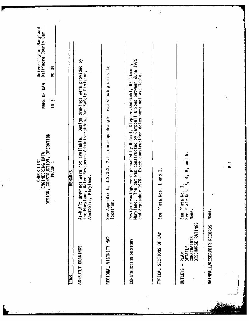
APPENDIX B
CHECK LISTENGINEERING DATA
DESIGN, CONSTRUCTION, OPERATIONPHASE 1
fuE
-0
00
S-o
W).- .cr wc 0))-
c~ M .- 0_IAE)
co > 0 .- = )
-o a to> M)
C to0
o4- 3 .C0)E0) .C d 4-)
Li 4ft 0)-V)n(A CO Oc
CCE E 1.-
0) M.-
3-- En
M C 0) a) a)00- r-- - 4-
0E~ 0
0O EEiSu00 LA c4) -a. .- <E -o
>n In - $C-- 0to al CO W 4) U
-E~V EuE S.- A&n CD0 v- 0.EnU (a) cL4A
")&J (D0- 0biL= t-C. L r 0) 4)3 u o
0-4f u ~ 3)0 En S- x
3e O =n- = 3) 4)( L At L .) CCe En1 S--x4
=*: - - 'Ai S-03-0 C.S 4) r-*En t
= : I toE r- .- r0) 0 00
fLJ c0 M 0 0 5-
1-E a x *3 - .a) 0 0 0
*-0 0 to-' EO4-J >-r- ) c 0) n 'aC.43 - -
5- CL 0 c.- 0L (dtot
CL 4-J En- V c- 0 CC
En.C 00 Wto a 0) 0))0 0
in 4 L"Of
CD w a- = m
C3 w
co~
CA La CD0l

CL
L.
E
E.0
4-W)E
4C,
.- S-
4->
> .c
to9- a) 0V-- S- to m
'V0
WIto 4-)4-
03W S- (r_ -0 0 a,
*L 0 4'- 0.0
C)/
uAJ
in4 I--C )(U).. I- > ) LJ
0. 1-4CD'-4
Cl (D C0 V)U) I-: C-L LLJ ) -J U)
LO LL I-- -CC0 w Wc )C
oD m. C3 vico40
x~u -j "- 0

IT
4l: 4-'
0 0
i0 0.
C C
'-4 0
LLI (
>- -o
U, I a - L
I---0 = Ut
C) u. C zcc~~- L)C)C )0 )"(
93- L)- UJ VJ-4 3LL. P0 cw -
oV -) 0)A 4- LJIU
a- 0A 0a- Lim JUCJ
...... ......

N.a
Cl)
-4
Lii0:: CAi
0 0 0
a) (3 )
V) d* j=i vii x
LL L/LJd
-CC
I--
.L C LLJ V)
C:))

APPENDIX C
PHOTOGRAPHS

3PHOTOGRAPH.
KEY MAP'
L .E AG.8,180 NATIONAL DAM INSPECTION PROGRAM .BcDASCALL-NONE I..C DAMDOR: JLM ICK:TED ACKENI4EIL & ASSOCIATES IST
ICONSULTING EINGINEERS STDWG. NO. C - I BALT IMORE, MO. j

-L-S- 4-)0.
CL)-~~ 0
0 f) 0 C4. 4- ) 4-3
4.D C) I-
E J to
-h r_, r
S E
-.. 0 ( -
CC) .0,'-
E 0 0
0 4-) 3 3
#a-) S - t,- 0 Inv0--' -
CL. 0- 0 (v Q
04 0,r r- E
_ 000 0
0,>4- 1 044
3 0 0 0
>.. r_ >) C))
-'r S- - 4 'r -)>)~ E- > -
C)
C)0 C0 C)

j*16 ~
c-I
C,
.........

4-) Cn4J) to 0=C
a- Wi 4-)
u ~ 4-)D
UQ m
4- 4-)0 C
CL 0
a-a)
4-) 4-)
a %-.~ to
Ct 0.003C- 0
0'S E- 4- 4-)c.u 04-) 0" 0E 10 LA N
30 300
4- * to.-000> >- ES
>4- SW 4.03D -0 WE Cii
UlI tl c'-Co
to CD Lo ~ CD
CD CD DC

'ftr

APPENDIX D
HYDROLOGIC AND HYDRAULICENGINEERING DATA
- * '

HYDROLOGIC AND HYDRAULICENGINEERING DATA
DRAINAGE AREA CHARACTERISTICS: Grassland (65%), urban development (20%),
woodland (15%).
ELEVATION TOP NORMAL POOL (STORAGE CAPACITY): N/A
ELEVATION TOP FLOOD CONTROL POOL (STORAGE CAPACITY): El. 178.0 (185.0 ac.-ft.)
ELEVATION MAXIMUM DESIGN POOL: El. 178.0
ELEVATION TOP DAM: El. 175.0
EMERGENCY SPILLWAY
a. Elevation El. 166.5b. Type Trapezodial Earth Channelc. Width 150 ft.d. Length 694 ft.e. Location Left abutmentf. Number and Type of Gates None
OUTLET WORKS
a. Type 36 in. dia, R.C. pipeb. Location 120 ft. left of right abutmentc. Entrance Invert El. 139.5d. Exit Invert El.,136.9e. Emergency Drawdown Facilities None
HYDROMETEOROLOGICAL GAGES
a. Type Noneb. Location Nonec. Records None
MAXIMUM NON-DAMAGING DISCHARGE 11,700 cfs
D-1

U.M.B.C. DAMHYDROLOGY REVIEW
Determine rainfall amount for PMF spillway design flood.
A. PMF rainfall for Baltimore County, Maryland
Approximately, 24 in./24 hr.
Rainfall obtained from Hydrometeorological Report No. 33.Based on 200 sq. mi. watershed.
B. Adjust rainfall for 6 hr. duration
Watershed area = 1.2 sq. mi.
Dam site located in Zone 6, therefore
24 in./24 hr. x 113% = 27.1 in./6 hr.
Adjustment factor obtained from Depth-Area-Duration Relation-ships, Hydrometeorological Report No. 33.
C. Adjust rainfall for drainage area.
Reduction factor = 0.8 (for watershed areas 10 sq. mi. or less)
Therefore, adjusted PMF rainfall =
0.8 x 27.1 in./6 hr. = 21.7 in./6 hr.
D-2
................... aw.

CHKD. BY ------- DATE --------- ------ ---- -, LJOS NO ................
U--
.. U5._ -. 5 , ,S-.t.:-;- eLT ?irM.
4. , C $ .c ,t4hTioMA.L E-NG.. 4'', ,-l , ---r 4 'to.,,Qo
WA.-c_- IA- C>
C, '7 . le
. .( t) 75
D-3
-'li lU ll lfll'lll I Vll I

CHKO. BY ------- DATE --------- JOB NO -------.----
-Tr -7 . ""F, - 7;.: - .
-.Aj -- t
vTp-mr, 7o A.7- 7 ooOC
.0 .1 0 o
z .6a .00i .Z74 7
4 I.3. c). , o O
-. 3.3 .047 I & -Z
4. @Zo i.7 44
c,44
to s -1>4 Z3 z-Z--0Z S&
I I T-. o z.z.4 zI.GC>
7.Z .Z4S Z..47 (700
-r.gZ. .I71 Z.47 Ioto
14.%24 Z.ez2.
VI tO.~~C. 1070 .b4C
8 .- Z .0(. 1.SZ- 477z-
IIs .01-1 4.04 se
RUMMEL. KLEPPR ft KAHL ENGINEERS D-4
" j.-. ; -I '; :

CHKD. BY - -- ATE . ,-----.-------- JOB 'NO -
-- - -- - -- - - -- - -- - - - -- - - - - - - ---------------
Z z.s.05o 4. z C->
- I 13.zC> O4 7 4.4-0
q2. 13 ,a(-* .045 4.71
14 GZ. .044. 4.!4 3oa
S .:4 o 4-c- sa .e _> 7- C
I G .034 5.(1I Z3,
" "I-/.IL. .z ..oao> t4
0 G7
t i=,-_... .oo eG.7
.o,4(. .0OZ 4.5, 14
F3 --- r.46-4 C, if QC)C-) 0f
-T^OL- 3. zI-7
I E' . C o
Z. .GG001 .Z_3C( < .
3 1.3Z ,CX-.V .47 zz.Z
5 Z.Lf.4 *.Z -7 .4 IS.Cs 3.30 .0=37 iIe - I
.04-7 1.47- 1e
S4.&z )G - 11..5 ZZ L77,
cs 01-1 l& :3 SZ-c>
I 5ZZ.7-3 1. IZ- e5-.
3.0;) z.3 , (
7.7 , .Z43 Z.Co-i57.c- z .171 &.,B-5 G95,3c--
3Z4 -5. o 4740
-Z 7 4 .OD-1 ".3--) 7

13 --- DATE ----------- SUBJECTYQ!119 -'- Lfl.., IIE NO..-- 4 - or OF
CHKO. BY---DATE.----------------------------~ JOB NO..
------------------- ---------- ----------- ---------------------------
U-7 472 e) ~
I 5 7 ouE~ 14 '40- z 3-C
P.~4. Z.4-) Z.~& I c3O
'ZbZ *C.)Qe 4.f
Z t -. 4 .0oZ5 %7 -L
%4.S) .044 17(05c)
Z- e. -7.' OZ

L~t~ ___
7 - - -- - - - - - - - -
---------

77
:717

APPENDIX E
LOCATION PLAN AND PLATES
I

RoWad%%%
/ I '~~' '-~$~. I
s> G G;fv , OPTL
31 StDe c P T PS
CONSULTIDG SITNES A ST______p____ RollOE Road 7_________

FLOOlD ODNTQOL IMPOUNDMENT PPOFILE
-- -----
OAIORE -MLN

DIKE. DETAIL,
X -
\ L~~~. 4* , '( * I -1n'O
I ' - ----- - Io
A\, ,,\ wi, t, M
77-7 '
! . .- "- " " CI .\.',
,N ,. m CAMUS OP PRO C-,CQ*
.lATE NO. I
-f N
It~~w~o cnr..I ma~ 4
PLT NO 1.
- - I -To*4.4 1Wirt

- ~~MATCH 10 SfE
- \~>~ - -/ -~
4:3 "AI'L
VV
cK P< '-n'RAVIN Q7/ ~ OT2L NQU~N5- O17A
RUMMEL KLPE/kKH
/ OSLW WE
- 'I e/ 5th, dN(AW
11111ff 1

---- *---fl -- fK ~
-FILL NFk OTI
]"A
PAT LA
-a
:1:PUS LOO RODMa
A
__TN Iox" m
0. mu "
PLATE NO. 2
9-c T"V

;44
QIPPOFIL ALL9NQ EC EMEROENCYP~ IPIWAY
~-6o
5, ,21 A 100 cA
- oRA ELON PEA CHNNL Tbk A 55
_ _ _ _ _ _ _ t_ _ _ _ _ _
suo ID? SL WNC, F3Lo 'GNJC QPIDA- ALN QAYY L
'vk-. -1 L. - l5*1 -.p .t -
c. ~ ~ - -ll c-1±h zo
'"!JAI'APPE 0M
MUOSE U~%TI OFOA- * P=WA PELLP FITIN)
t~ ~OO~ O SottCUMMELOOC KLEP P 8 KLAL
&d'C~~~OdSUTIN ENGINEERS.WJ ~W6MALIMR MARYLANDi 1A
0.
t. ore FtC",OA. JI

PDOFILE ALOt& C PR QNCIPAL 5PILWAY
- UR
- A 14B NI: L>.LAP0 LODCOTOANSE CLA
LVOKE DEAI DEAL HE
&JI A +PROFILE~~~"c ALNOCDA CTOf EC
alo MPU LOOP ROA
PLAT EE NO.lIN3

067 .Nell
.4-~~~' 1*- ".0
w-0- C--5 up 9 50 GA
-toF.W .
LoC.. f';,~2
L- - -- -te - -~c -- - -
K-- 2. -AF_
L ELEVATION - HEA
9Fl1sh .. ,th topf 40~f,
aof0.(..pcal 6 .dth of wI <
1: 1no j U- . lopot splic.
"0 F F. 1I
INGWALLh.;ght of -o11
H5
_33.'790FF. DETAIL A
6~dSI-R . -4* RP F 0. -77o. t776I
t; - El.9 00
v~ r:
I* 0
SECTION F-F
r-0.
.. ? I < 'd .. g
9
'77-T-7

.5* -4
P.01d '-f -4.0or
-'4.6 1e Fw F. -I
*121
T~ tet 0:l
.21-- OFF SECTION. H-HJ-O -. H EA0W L
O~E F
0E IF 1z Z
__F Fil f7 sDETAIL/LB IC
Pp.4t om ,b 'o 2al.Clt
2020 Co'e v;or-
0 ~-1** ~T-1
0 1. IID3* 7 -1 fl. - .00
I L
,ETO -otrdPA PO
E1,1413. 40 0.r ;
STRUCTURE NOTESbt -All C-1.s..0shallt- . M 8d., -,n ,,t.ot t0.tt of
0 0rs .
51.1o~~tan sto l -of-r to reop.i ts of AS TM. . f to*~ ~ ~ ~ ~ A 4. as50 oroonood to dot.. ltart.t qrn. Os-f-r of r-~foro,9
Coos. F01.r> .?ll ae,,-t coo 001bo .dod T00,011 rOnf- - - -f ft- . pt ofr-
*Cotlcf-htrodo -eosar4 sulot bar., 4-o, ft. to
G'.Ptf Pm 'Art bplas *0011 b 24 bor d-bom~tr otopt het,% nolod ottrei,.
f A. boobf irq 11101=f os qoo Itb1jot.f 1, n .dlo. -tlil fofl .- - - 0106Ib4 -11 5.5P10 .a bl.. rslinq dooqn stresso..
CO~~b L~~lO .01 oo td areas shtolt be t..pl drq4 -0f I hocfill h~o. ho,.i PiaodSAll 51tror Steel .. kt shllt be AZ.TM, A-.3G Cl...qnotfoo rft.9
_..TflW THRO4GH RAIN & F16TgR t.ishlmarpMd
mo.t h, 5oot. IMPACT BASINSFLOO CONTROL DETAIL SHEET .
CAPSLOOP ROAD owft oAml
UNIVEIY * *NYLA~ SI -13"L.TIME COUNTY. MD-
S--PLATE NO. 4

k>
* ~ ~ ~ Z7?, s".
5co.: i0
b~
_FtAN __jf SCTION 8-8
Tro . .'R k 2- C.- -5 (- FYOF f-o Onl')
f!- 410R..Orf.. 7- -
Top bl C ri r pl )~on
tow in -j-~ . F~~,n
A - b."L.
F. sAlO 11 F.Les --G F r c e-' f
1,O' C.- f~t1
"Vo~L~~ 5. 1 .dI N. -f~
1RA~~fACK TO'P'T4
RUMMEL, KLEPPER IS KAH4LCONJSULTING ENGINEERSBALTIMORE. MARYLAND

-* Ir M~s E. 'l9
4- h, D-.4-N.-.
tA 4, Ia.
WINWAL PLANi'.t
XX~~~~~~~ 1II I ~ - .. H-III -l
0. 1, 11 . TFi G
-4 ENo --- --------
1i --
1E __: ;
.a~~. R.ff----
a 0- pA10SCIO -
o WINGWALL ELEVATION-
'tFo d ."d **~ ~_b-' -4l RF -45 __
SECTION E-E 's' SECTION O-D
W_.INGWALL DETAILS - IMPACT BASIN
FLOOD CONTROL DETAIL SHEET
SI -14
_____ -PLATE NO.S 5
VIA

N
RuML KL R A
COSLTN ENIER.ATI M S..YA

. . . . " ". 0*: 0. *"'". b t
01A
3 005 0, tO 0550t lA.
*" N - - - ----- -- - , -t.!
SIIt
INITIAL ' TQAM CHAN N[I EiCAVA11ON-
EROSION a SEDIME.TAION CONTROL PLAN,
UNIVEIT ?Y OF WARY]LAND ~
SI-1
*zI~~0' IsZOWE'S
PLATE NO. 6
['I AN ,V8' 8, ,,,,, I "'A... ,.. 5.5

APPENDIX F
REGIONAL GEOLOGY
I- I -,w ,,

U.M.B.C. DAMNDI ID NO. MD 34REGIONAL GEOLOGY
The U.M.B.C. Dam is located approximately one mile southwest of the Balti-
more city limit in Catonsville, Maryland. The dam is situated on theeastern edge of the Fall Line Zone.
In generaal, the Laurel Belt crystalline rocks of Cambrian Age lie to thewest of the U.M.B.C. campus, and the Potomac Group Sediments, of LowerCretaceous Age, lie to the east. These rock and soil formations aremembers of the Upland Piedmont and Coastal Plain Provinces, respectively.
The dam was probably constructed in sandy alluvium of Quaternary Age,transported by the west branch of Herbert Run. The Patuxent Formation ofLower Cretaceous Age underlies these alluvium deposits, and consistspredominately of sand, gravel and clay.
References
Crowley, William P.; Reinhardt, Juergen; and Cleaves, Emery T.; GeologicMap of Baltimore County and City; State of Maryland Geological Survey,1976.
F-1

\ -)LAUREL BELT"\ 3
ROCKSe v
/ ZeILAUREL BELT't\GROUP KyCRYSTALLINE ROCKS
w~w b POTOMAC GROUP..
Germ
_ QUATERNARY
v POTPOTO'AC-
GROUNFREPROPSFOMTO CNAT
LAURE BELTLiN GNIEROUP
o RSALN ROC. N- ATMRM.I______ .