Embed Size (px)
Citation preview
Approved for public release; distribution is unlimitedMarshall Space Flight Center, Export Control Authority, Amelia Oneil ES13
FEATHERSAIL – THE NEXT GENERATION OF NANO-CLASS SAIL VEHICLE
D.C. AlhornMarshall Space Flight Center (MSFC)
Huntsville, Alabama
ABSTRACT
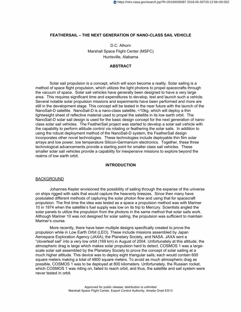
Solar sail propulsion is a concept, which will soon become a reality. Solar sailing is a method of space flight propulsion, which utilizes the light photons to propel spacecrafts through the vacuum of space. Solar sail vehicles have generally been designed to have a very large area. This requires significant time and expenditures to develop, test and launch such a vehicle. Several notable solar propulsion missions and experiments have been performed and more are still in the development stage. This concept will be tested in the near future with the launch of the NanoSail-D satellite. NanoSail-D is a nano-class satellite, <10kg, which will deploy a thin lightweight sheet of reflective material used to propel the satellite in its low earth orbit. The NanoSail-D solar sail design is used for the basic design concept for the next generation of nano-class solar sail vehicles. The FeatherSail project was started to develop a solar sail vehicle with the capability to perform attitude control via rotating or feathering the solar sails. In addition to using the robust deployment method of the NanoSail-D system, the FeatherSail design incorporates other novel technologies. These technologies include deployable thin film solar arrays and low power, low temperature Silicon-Germanium electronics. Together, these three technological advancements provide a starting point for smaller class sail vehicles. These smaller solar sail vehicles provide a capability for inexpensive missions to explore beyond the realms of low earth orbit.
INTRODUCTION
BACKGROUND
Johannes Kepler envisioned the possibility of sailing through the expanse of the universe on ships rigged with sails that would capture the heavenly breezes. Since then many have postulated different methods of capturing the solar photon flow and using that for spacecraft propulsion. The first time the idea was tested as a space a propulsion method was with Mariner 10 in 1974 when the satellite’s fuel supply was low on its trip to Mercury. Scientists angled the solar panels to utilize the propulsion from the photons in the same method that solar sails work. Although Mariner 10 was not designed for solar sailing, the propulsion was sufficient to maintain Mariner’s course.
More recently, there have been multiple designs specifically created to prove the propulsion while in Low Earth Orbit (LEO). These include missions assembled by Japan Aerospace Exploration Agency (JAXA), the Planetary Society, and NASA. JAXA sent a “cloverleaf sail” into a very low orbit (169 km) in August of 2004. Unfortunately at this altitude, the atmospheric drag is large which makes solar propulsion hard to detect. COSMOS 1 was a large-scale solar sail assembled by the Planetary Society to prove the concept of solar sailing at a much higher altitude. This device was to deploy eight triangular sails; each would contain 600 square meters making a total of 4800 square meters. To avoid as much atmospheric drag as possible, COSMOS 1 was to be deployed at 800 kilometers. Unfortunately, the Russian rocket,which COSMOS 1 was riding on, failed to reach orbit, and thus, the satellite and sail system werenever tested in orbit.
https://ntrs.nasa.gov/search.jsp?R=20100035087 2018-05-30T20:12:56+00:00Z
NASA’s Marshall Space Flight Center concluded in 2006 its solar sail mission development project under NASA’s New Millennium program. The ST9-SSM project was an ambitious development of a 20m sail for ground deployment. Although this project did not continue after the ground tests, it did provide a learning experience for the solar sail community. In 2007, a small group of engineers at MSFC began a sail development for a nano-class satellite. Nano-satellites are typically < 10kg and have limited capabilities. Thus the CubeSail project started in hopes of developing a precursor demonstration mission. In early 2008, the CubeSail project was offered a flight opportunity and thus the NanoSail-D flight program began.
The goal of the NanoSail-D project was to quickly deliver the sail subsystem that was envisioned with the CubeSail effort. After an intense four-month effort, two satellites were designed, manufactured and tested. The launch vehicle for the NanoSail-D mission was the third launch of SpaceX’s Falcon 1 rocket. In August 2008, the dream of solar sails was about to be realized. Unfortunately, like the Cosmos 1 mission, the rocket failed to reach orbit resulting in the loss of the first NanoSail-D unit.
RECENT DEVELOPMENTS
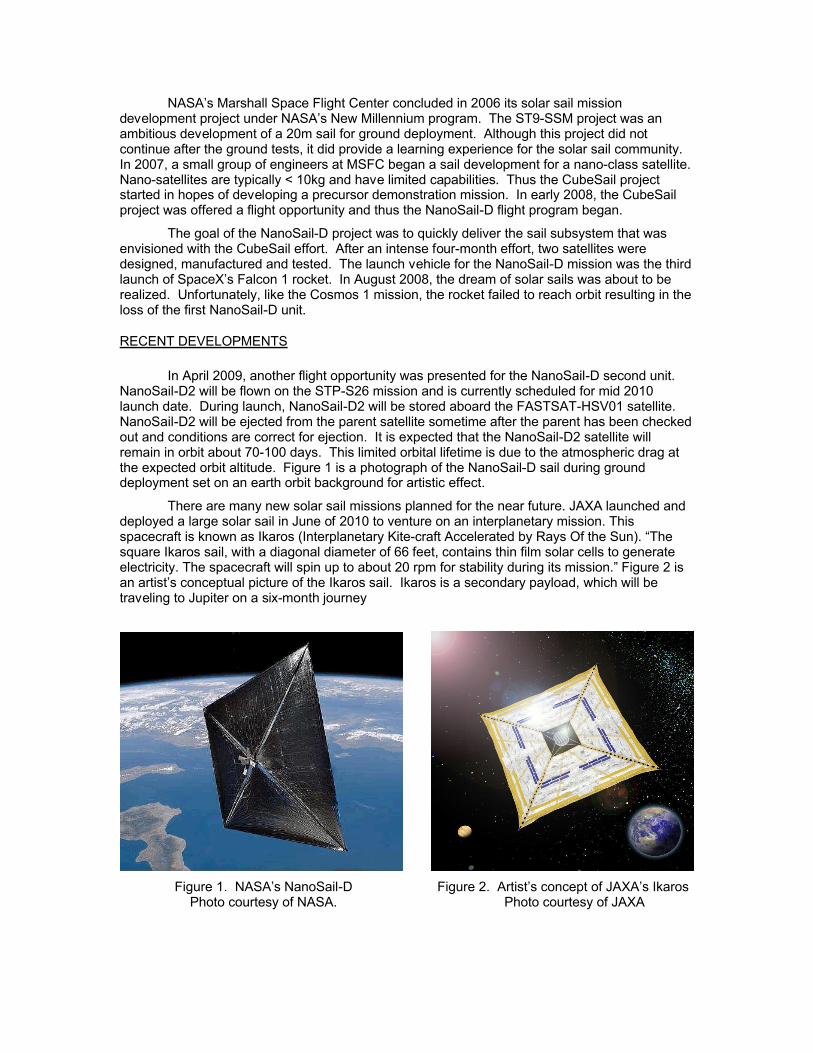
In April 2009, another flight opportunity was presented for the NanoSail-D second unit. NanoSail-D2 will be flown on the STP-S26 mission and is currently scheduled for mid 2010 launch date. During launch, NanoSail-D2 will be stored aboard the FASTSAT-HSV01 satellite. NanoSail-D2 will be ejected from the parent satellite sometime after the parent has been checked out and conditions are correct for ejection. It is expected that the NanoSail-D2 satellite will remain in orbit about 70-100 days. This limited orbital lifetime is due to the atmospheric drag at the expected orbit altitude. Figure 1 is a photograph of the NanoSail-D sail during ground deployment set on an earth orbit background for artistic effect.
There are many new solar sail missions planned for the near future. JAXA launched and deployed a large solar sail in June of 2010 to venture on an interplanetary mission. This spacecraft is known as Ikaros (Interplanetary Kite-craft Accelerated by Rays Of the Sun). “The square Ikaros sail, with a diagonal diameter of 66 feet, contains thin film solar cells to generate electricity. The spacecraft will spin up to about 20 rpm for stability during its mission.” Figure 2 is an artist’s conceptual picture of the Ikaros sail. Ikaros is a secondary payload, which will be traveling to Jupiter on a six-month journey
Figure 1. NASA’s NanoSail-D Figure 2. Artist’s concept of JAXA’s IkarosPhoto courtesy of NASA. Photo courtesy of JAXA

The Planetary Society has recently received funding for their “LightSail” project. This project will consist of three different sail missions starting with the first deployment in 2010. The first of these, named LightSail-1, will be very similar to NanoSail-D both in size and boom design. The second flight will carry a sail capable of increasing the altitude of the sail’s orbit by increasing orbital speed. Finally, the third sail would have the capability to break out of earth orbit where solar sails are said to perform best. Also there has been rumors of a COSMOS-2 mission, but the Planetary Society’s major efforts are currently focused on the LightSail project.
NEXT GENERATION OF SAIL VEHICLE DESIGN CONSIDERATIONS
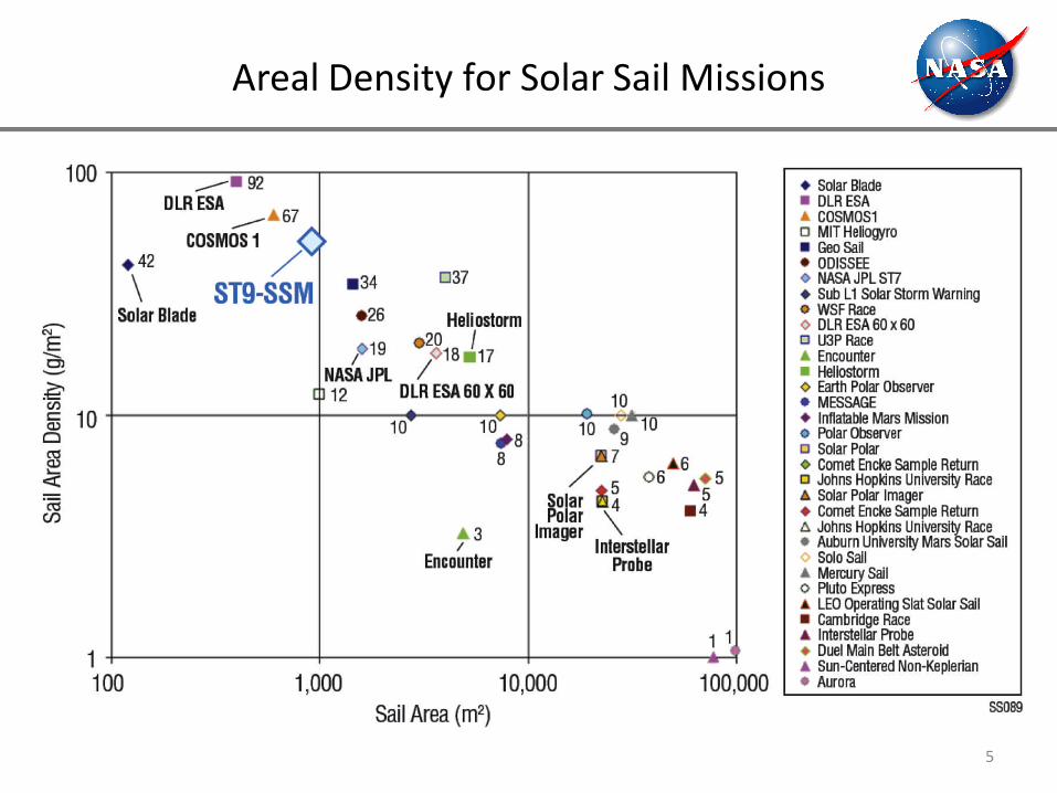
All of the previous sail vehicle projects have the same goal. Proving the deployment of the sail and determining the extent of solar propulsion. With the successful orbital NanoSail-D2 deployment, it necessary to focus on how to apply the design capabilities of the NanoSail-D system to the next generation of solar sail vehicles. The basic consideration for sail vehicles is the sail area density, or areal density. Areal density is the total vehicle mass divided by the total sail area. This basic parameter defines the capability of the concept to successfully perform many scientific and research missions. Figure 3 is a chart of the performance requirements from the ST9-SSM project.
Figure 3. – Performance Requirements for Potential Solar Sail MissionsPhoto courtesy of NASA ST9-SSM
When trying to go beyond a basic proof of concept, there are a few key issues addressed with the FeatherSail design. First, NanoSail-D had an aerial density of 380 g/m2 with an overall sail area of 10 m2. There is enough volume in the NanoSail-D sail compartment to store 40m2 of sail material. With longer booms, the areal density of a fully packaged NanoSail-D vehicle would approach the upper line on the previous chart.
One design consideration is the limited mass available to the payload. Since the areal density must inherently be low, the payload and all avionics must be minimized. In deep space,the main considerations are power and the ability to survive the increased radiation subjected to the vehicle. Ikaros will attempt to solve the power problem by incorporating the solar cells in the sail material. The practicality of this method is yet to be determined. Another method is to lower the power consumption of the payload and miniaturize or limit the functions on a single vehicle.
The next design issue to be considered is the ability to steer the vehicle. When the vehicle is in near earth orbit torque rods can be used with limited capability as the orbit increases. Reaction wheels and Control Momentum Gyroscopes (CMGs) can be used for attitude control, but there is a limit to which they can be used until they reach saturation or gimbal lock. Then there must be some other means to desaturate the reaction wheel or unlock the CMG. In low earth orbit, the common method is to use torque rods, but these are unusable in the orbits in which solar sail vehicles are not affected by atmospheric drag or out in deep space. Steerable sails give the vehicle the capability to not only provide for propulsion, but also control the attitude of the vehicle. This method provides an alternative to desaturate a reaction wheel or unlock a CMG.
FEATHERSAIL – SECOND GENERATION NANOSAIL CONCEPT
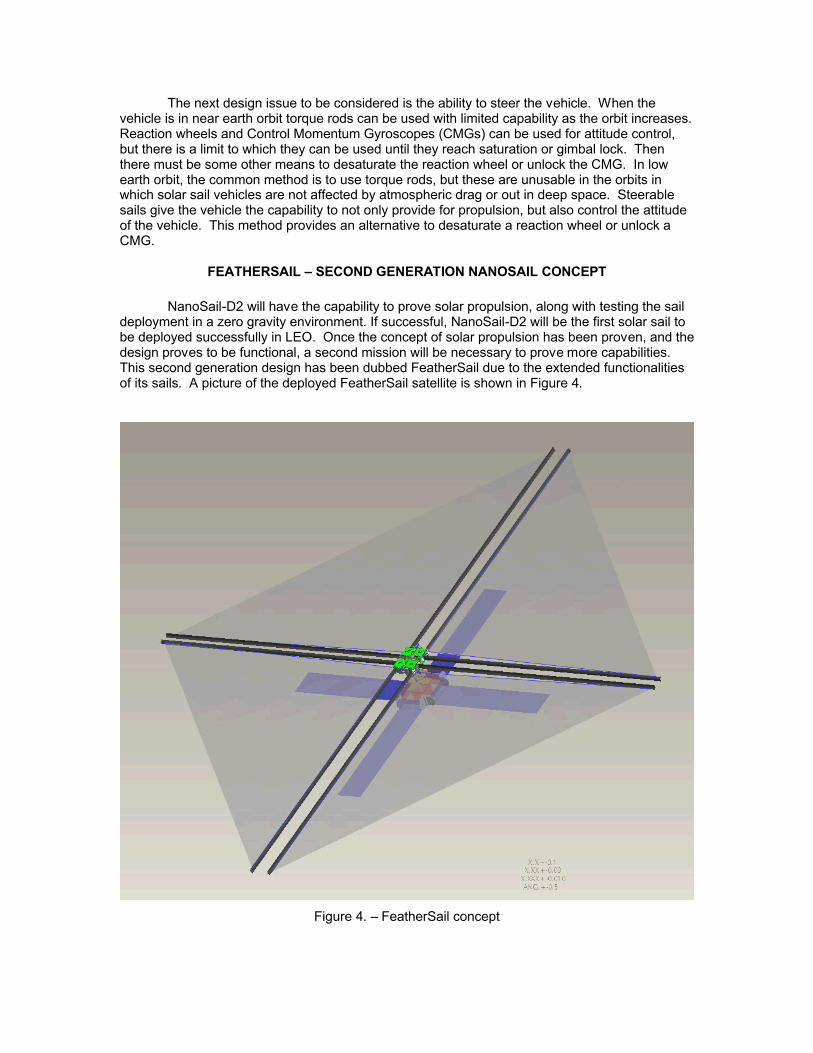
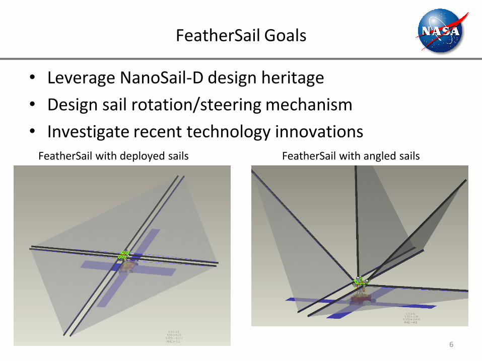
NanoSail-D2 will have the capability to prove solar propulsion, along with testing the sail deployment in a zero gravity environment. If successful, NanoSail-D2 will be the first solar sail to be deployed successfully in LEO. Once the concept of solar propulsion has been proven, and the design proves to be functional, a second mission will be necessary to prove more capabilities. This second generation design has been dubbed FeatherSail due to the extended functionalities of its sails. A picture of the deployed FeatherSail satellite is shown in Figure 4.
Figure 4. – FeatherSail concept
The goal of the FeatherSail design concept is to leverage recent technological innovations necessary to meet the needs of long duration deep space missions. These innovations are: Dependable sail deployment systems; Steerable solar sails; Deployable thin film solar arrays; Low temperature, radiation tolerant Silicon-Germanium (SiGe) electronics. Demonstration of these technologies in a relatively inexpensive nanosatellite vehicle would provide the impetus for larger sail systems to be realized.
AERIAL DENSITY REDUCTION
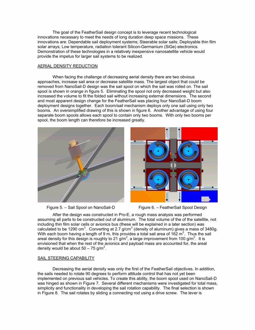
When facing the challenge of decreasing aerial density there are two obvious approaches, increase sail area or decrease satellite mass. The largest object that could be removed from NanoSail-D design was the sail spool on which the sail was rolled on. The sail spool is shown in orange in figure 5. Eliminating the spool not only decreased weight but also increased the volume to fit the folded sail without increasing external dimensions. The second and most apparent design change for the FeatherSail was placing four NanoSail-D boom deployment designs together. Each boom/sail mechanism deploys only one sail using only two booms. An oversimplified drawing of this is shown in figure 6. Another advantage of using four separate boom spools allows each spool to contain only two booms. With only two booms per spool, the boom length can therefore be increased greatly.
Figure 5. – Sail Spool on NanoSail-D Figure 6. – FeatherSail Spool Design
After the design was constructed in Pro-E, a rough mass analysis was performed assuming all parts to be constructed out of aluminum. The total volume of the of the satellite, not including thin film solar cells or avionics bus (these will be explained in a later section) was calculated to be 1290 cm3. Converting at 2.7 g/cm3 (density of aluminum) gives a mass of 3480g. With each boom having a length of 9 m, this provides a total sail area of 162 m2. Thus the sail areal density for this design is roughly to 21 g/m2, a large improvement from 100 g/m2. It is envisioned that when the rest of the avionics and payload mass are accounted for, the areal density would be about 50 – 75 g/m2.
SAIL STEERING CAPABILITY
Decreasing the aerial density was only the first of the FeatherSail objectives. In addition, the sails needed to rotate 90 degrees to perform attitude control that has not yet been implemented on previous sail vehicles. To create this ability, the boom spool used on NanoSail-Dwas hinged as shown in Figure 7. Several different mechanisms were investigated for total mass, simplicity and functionality in developing the sail rotation capability. The final selection is shown in Figure 8. The sail rotates by sliding a connecting rod using a drive screw. The lever is
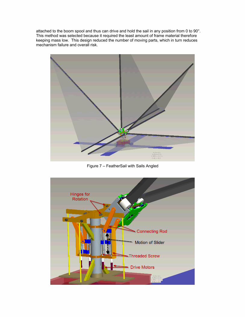
attached to the boom spool and thus can drive and hold the sail in any position from 0 to 90°. This method was selected because it required the least amount of frame material therefore keeping mass low. This design reduced the number of moving parts, which in turn reducesmechanism failure and overall risk.
Figure 7 – FeatherSail with Sails Angled
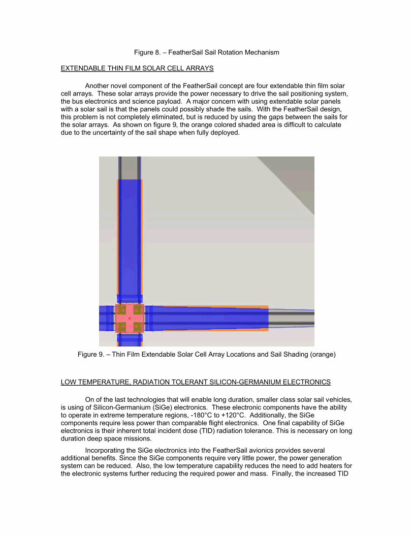
Figure 8. – FeatherSail Sail Rotation Mechanism
EXTENDABLE THIN FILM SOLAR CELL ARRAYS
Another novel component of the FeatherSail concept are four extendable thin film solar cell arrays. These solar arrays provide the power necessary to drive the sail positioning system, the bus electronics and science payload. A major concern with using extendable solar panels with a solar sail is that the panels could possibly shade the sails. With the FeatherSail design, this problem is not completely eliminated, but is reduced by using the gaps between the sails for the solar arrays. As shown on figure 9, the orange colored shaded area is difficult to calculate due to the uncertainty of the sail shape when fully deployed.
Figure 9. – Thin Film Extendable Solar Cell Array Locations and Sail Shading (orange)
LOW TEMPERATURE, RADIATION TOLERANT SILICON-GERMANIUM ELECTRONICS
On of the last technologies that will enable long duration, smaller class solar sail vehicles,is using of Silicon-Germanium (SiGe) electronics. These electronic components have the ability to operate in extreme temperature regions, -180°C to +120°C. Additionally, the SiGe components require less power than comparable flight electronics. One final capability of SiGe electronics is their inherent total incident dose (TID) radiation tolerance. This is necessary on long duration deep space missions.
Incorporating the SiGe electronics into the FeatherSail avionics provides several additional benefits. Since the SiGe components require very little power, the power generation system can be reduced. Also, the low temperature capability reduces the need to add heaters for the electronic systems further reducing the required power and mass. Finally, the increased TID
capability reduces or possibly eliminates the electronics shielding. Combined, these factors make the inclusion of SiGe electronics an advantage for long duration sail missions.
SUMMARY AND CONCLUSIONS
The FeatherSail conceptual design is based upon emerging and recently developed technologies. Together, these technologies provide solar sail vehicle capabilities previously not achievable. The steerable sails provide an attitude control capability realized with the FeatherSail concept. Incorporating SiGe electronics provides a wealth of mass and power savings and therefore reduces the size of the bus and payload avionics. The thin film solar cells could be used in small deployable arrays, or could be incorporated into the sail membrane to further reduce mass. Reliable sail deployment systems, allow mission designers to utilize multiple FeatherSail pods together to achieve larger sail vehicles and further reduce areal density.
The FeatherSail concept has the possibility to open new worlds to science exploration. NASA has the opportunity with this design to take the next step towards interplanetary solar sail travel and to enable propellantless propulsion for space vehicles and satellites. In addition, multiple small FeatherSail vehicles could be flown together to amortize the development and launch costs for larger mission scenarios. In conclusion, the FeatherSail concept creates an opening into future propulsion methods enabling much greater distance travel in a shorter amount of time.

REFERENCES
1. Scheierl, J. M. and Alhorn, D. C., Solar Sails: Design and Future Impact, NASA/MSFC/USRP Fall 2009 Intern Research Paper, Huntsville, AL (December 2009).
2. Vulpetti, G., Johnson, L., and Matloff, G.L., Solar Sails a Novel Approach to Interplanetary Travel, Praxis Publishing, New York, (2008).
3. Darling, D., “Solar Sail,” The Internet Encyclopedia of Science [online database], URL: http://www.daviddarling.info/encyclopedia/S/solar_sail.html (cited 15 December 2009).
4. Coulter, D., and Phillips, T., “A Brief History of Solar Sails,” Science @ NASA [online database], URL: http://science.nasa.gov/headlines/y2008/31jul_solarsails.htm (cited 15 December 2009).
5. Leary, W., “Into Orbit (Maybe Beyond) on Wings of Giant Solar Sails” New York Times, online, (21 June 2009).
6. Stanford, N., “Hoisting the Solar Sail,” Chemistry World [online database], URL: http://www.rsc.org/chemistryworld/Issues/2009/July/HoistingTheSolarSail.asp (cited 15 December 2009).
7. Pappa, R., Lassiter, J., and Ross, B., Structural Dynamics Experimental Activities in Ultra-Lightweight and Inflatable Space Structures, NASA TM-2001-210857, (2001).
8. Clark, S., “Two solar sailing trials readied for launch next year,” Spaceflight Now [online database], URL: http://spaceflightnow.com/news/n0911/10solarsails/ (cited 15 December 2009).
9. Overbye, D., “Setting Sail Into Space Propelled by Sunshine,” New York Times, online, (9 November. 2009).
10. Whorton, M. S, Heaton, A., Pinson, R., Laue, G., Adams, C., “NanoSail-D: The First Flight Demonstration of Solar Sails for Nanosatellites,” AIAA/USU 22nd Conference on Small Satellites, SSC08-X-1, (August 2008).
11. Friedman, L. D., “Projects: LightSail - The Future of Solar SailingLightSail: A New Way and a New Chance to Fly on Light,” The Planetary Society [online article], http://www.planetary.org/programs/projects/solar_sailing/tpr_lightsail.html (cited 25 March 2010).
GLOSSARY
CMG – Control Momentum GyroscopeIkaros – Interplanetary Kite-craft Accelerated by Rays Of the SunJAXA – Japan Aerospace Exploration AgencyLEO – Low-Earth OrbitMSFC – Marshall Space Flight CenterNASA – National Aeronautics and Space AdministrationSiGe – Silicon-GermaniumST9-SSM – Space Technology 9 – Solar Sail MissionSTP – Space Test programTID – Total Incident Dose

FeatherSail – The Next Generation ofNano-Class Sail Vehicle
D. C. AlhornNASA/Marshall Space Flight Center
Huntsville, [email protected]
Approved for public release; distribution is unlimitedMarshall Space Flight Center, Export Control Authority, Amelia Oneil ES13
Outline
• Purpose of FeatherSail Study
• Brief Solar Sail History
• Areal Density for Solar Sail Missions
• FeatherSail design– NanoSail-D Heritage
– Sail Rotation/Steering Mechanism
– Recent Technology Innovations
• FeatherSail Animation
• Future Directions
2
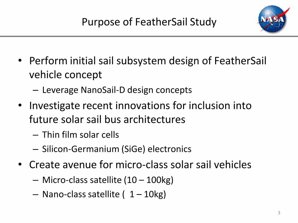
Purpose of FeatherSail Study
• Perform initial sail subsystem design of FeatherSail vehicle concept– Leverage NanoSail-D design concepts
• Investigate recent innovations for inclusion into future solar sail bus architectures– Thin film solar cells
– Silicon-Germanium (SiGe) electronics
• Create avenue for micro-class solar sail vehicles– Micro-class satellite (10 – 100kg)
– Nano-class satellite ( 1 – 10kg)
3

Brief History on Solar Sail Technology Development and missions
• NASA– Mariner 10 – (1970’s)
– NASA – ST9-SSM (2006)
– NASA’s – NanoSail-D (2008), NanoSail-D2 (2010)
• Russian– Znamya 2 & 2.5 – (1993, 1999)
• JAXA– “Cloverleaf” – (2004)
– Solar Sail Payload – (2006)
– Ikaros – (2010)
• The Planetary Society– COSMOS 1 – (2005)
– LightSail – (2010?)
4
Areal Density for Solar Sail Missions
5
FeatherSail Goals
• Leverage NanoSail-D design heritage
• Design sail rotation/steering mechanism
• Investigate recent technology innovationsFeatherSail with deployed sails FeatherSail with angled sails
6
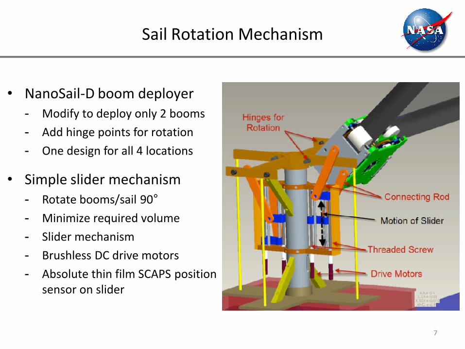
Sail Rotation Mechanism
• NanoSail-D boom deployer- Modify to deploy only 2 booms
- Add hinge points for rotation
- One design for all 4 locations
• Simple slider mechanism- Rotate booms/sail 90°- Minimize required volume
- Slider mechanism
- Brushless DC drive motors
- Absolute thin film SCAPS position sensor on slider
7
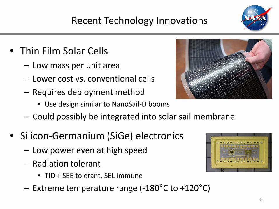
Recent Technology Innovations
• Thin Film Solar Cells– Low mass per unit area
– Lower cost vs. conventional cells
– Requires deployment method• Use design similar to NanoSail-D booms
– Could possibly be integrated into solar sail membrane
• Silicon-Germanium (SiGe) electronics– Low power even at high speed
– Radiation tolerant• TID + SEE tolerant, SEL immune
– Extreme temperature range (-180°C to +120°C)8

FeatherSail Animation
9

Future Directions
• FeatherSail concept opens new class of solar sail vehicles– Lower cost with common design
– Smaller vehicles reduce launch cost
– More potential launch opportunities
– Multiple sail pods could make larger sail vehicle
• Multiple vehicle mission scenarios possible with smaller class vehicle– Earth Magneto-tail
– Comet Rendezvous
10